EP3361625A1 - Motor driving apparatus and home appliance comprising same - Google Patents
Motor driving apparatus and home appliance comprising same Download PDFInfo
- Publication number
- EP3361625A1 EP3361625A1 EP16853933.6A EP16853933A EP3361625A1 EP 3361625 A1 EP3361625 A1 EP 3361625A1 EP 16853933 A EP16853933 A EP 16853933A EP 3361625 A1 EP3361625 A1 EP 3361625A1
- Authority
- EP
- European Patent Office
- Prior art keywords
- motor
- frequency
- inverter
- phase current
- driving apparatus
- Prior art date
- Legal status (The legal status is an assumption and is not a legal conclusion. Google has not performed a legal analysis and makes no representation as to the accuracy of the status listed.)
- Granted
Links
Images




Classifications
-
- H—ELECTRICITY
- H02—GENERATION; CONVERSION OR DISTRIBUTION OF ELECTRIC POWER
- H02P—CONTROL OR REGULATION OF ELECTRIC MOTORS, ELECTRIC GENERATORS OR DYNAMO-ELECTRIC CONVERTERS; CONTROLLING TRANSFORMERS, REACTORS OR CHOKE COILS
- H02P27/00—Arrangements or methods for the control of AC motors characterised by the kind of supply voltage
- H02P27/04—Arrangements or methods for the control of AC motors characterised by the kind of supply voltage using variable-frequency supply voltage, e.g. inverter or converter supply voltage
- H02P27/06—Arrangements or methods for the control of AC motors characterised by the kind of supply voltage using variable-frequency supply voltage, e.g. inverter or converter supply voltage using DC to AC converters or inverters
- H02P27/08—Arrangements or methods for the control of AC motors characterised by the kind of supply voltage using variable-frequency supply voltage, e.g. inverter or converter supply voltage using DC to AC converters or inverters with pulse width modulation
- H02P27/085—Arrangements or methods for the control of AC motors characterised by the kind of supply voltage using variable-frequency supply voltage, e.g. inverter or converter supply voltage using DC to AC converters or inverters with pulse width modulation wherein the PWM mode is adapted on the running conditions of the motor, e.g. the switching frequency
-
- A—HUMAN NECESSITIES
- A47—FURNITURE; DOMESTIC ARTICLES OR APPLIANCES; COFFEE MILLS; SPICE MILLS; SUCTION CLEANERS IN GENERAL
- A47L—DOMESTIC WASHING OR CLEANING; SUCTION CLEANERS IN GENERAL
- A47L9/00—Details or accessories of suction cleaners, e.g. mechanical means for controlling the suction or for effecting pulsating action; Storing devices specially adapted to suction cleaners or parts thereof; Carrying-vehicles specially adapted for suction cleaners
- A47L9/28—Installation of the electric equipment, e.g. adaptation or attachment to the suction cleaner; Controlling suction cleaners by electric means
- A47L9/2836—Installation of the electric equipment, e.g. adaptation or attachment to the suction cleaner; Controlling suction cleaners by electric means characterised by the parts which are controlled
- A47L9/2842—Suction motors or blowers
-
- A—HUMAN NECESSITIES
- A47—FURNITURE; DOMESTIC ARTICLES OR APPLIANCES; COFFEE MILLS; SPICE MILLS; SUCTION CLEANERS IN GENERAL
- A47L—DOMESTIC WASHING OR CLEANING; SUCTION CLEANERS IN GENERAL
- A47L9/00—Details or accessories of suction cleaners, e.g. mechanical means for controlling the suction or for effecting pulsating action; Storing devices specially adapted to suction cleaners or parts thereof; Carrying-vehicles specially adapted for suction cleaners
- A47L9/28—Installation of the electric equipment, e.g. adaptation or attachment to the suction cleaner; Controlling suction cleaners by electric means
-
- A—HUMAN NECESSITIES
- A47—FURNITURE; DOMESTIC ARTICLES OR APPLIANCES; COFFEE MILLS; SPICE MILLS; SUCTION CLEANERS IN GENERAL
- A47L—DOMESTIC WASHING OR CLEANING; SUCTION CLEANERS IN GENERAL
- A47L9/00—Details or accessories of suction cleaners, e.g. mechanical means for controlling the suction or for effecting pulsating action; Storing devices specially adapted to suction cleaners or parts thereof; Carrying-vehicles specially adapted for suction cleaners
- A47L9/28—Installation of the electric equipment, e.g. adaptation or attachment to the suction cleaner; Controlling suction cleaners by electric means
- A47L9/2857—User input or output elements for control, e.g. buttons, switches or displays
-
- A—HUMAN NECESSITIES
- A47—FURNITURE; DOMESTIC ARTICLES OR APPLIANCES; COFFEE MILLS; SPICE MILLS; SUCTION CLEANERS IN GENERAL
- A47L—DOMESTIC WASHING OR CLEANING; SUCTION CLEANERS IN GENERAL
- A47L9/00—Details or accessories of suction cleaners, e.g. mechanical means for controlling the suction or for effecting pulsating action; Storing devices specially adapted to suction cleaners or parts thereof; Carrying-vehicles specially adapted for suction cleaners
- A47L9/28—Installation of the electric equipment, e.g. adaptation or attachment to the suction cleaner; Controlling suction cleaners by electric means
- A47L9/2868—Arrangements for power supply of vacuum cleaners or the accessories thereof
-
- H—ELECTRICITY
- H02—GENERATION; CONVERSION OR DISTRIBUTION OF ELECTRIC POWER
- H02P—CONTROL OR REGULATION OF ELECTRIC MOTORS, ELECTRIC GENERATORS OR DYNAMO-ELECTRIC CONVERTERS; CONTROLLING TRANSFORMERS, REACTORS OR CHOKE COILS
- H02P21/00—Arrangements or methods for the control of electric machines by vector control, e.g. by control of field orientation
- H02P21/0085—Arrangements or methods for the control of electric machines by vector control, e.g. by control of field orientation specially adapted for high speeds, e.g. above nominal speed
-
- H—ELECTRICITY
- H02—GENERATION; CONVERSION OR DISTRIBUTION OF ELECTRIC POWER
- H02P—CONTROL OR REGULATION OF ELECTRIC MOTORS, ELECTRIC GENERATORS OR DYNAMO-ELECTRIC CONVERTERS; CONTROLLING TRANSFORMERS, REACTORS OR CHOKE COILS
- H02P21/00—Arrangements or methods for the control of electric machines by vector control, e.g. by control of field orientation
- H02P21/14—Estimation or adaptation of machine parameters, e.g. flux, current or voltage
-
- H—ELECTRICITY
- H02—GENERATION; CONVERSION OR DISTRIBUTION OF ELECTRIC POWER
- H02P—CONTROL OR REGULATION OF ELECTRIC MOTORS, ELECTRIC GENERATORS OR DYNAMO-ELECTRIC CONVERTERS; CONTROLLING TRANSFORMERS, REACTORS OR CHOKE COILS
- H02P21/00—Arrangements or methods for the control of electric machines by vector control, e.g. by control of field orientation
- H02P21/14—Estimation or adaptation of machine parameters, e.g. flux, current or voltage
- H02P21/18—Estimation of position or speed
-
- H—ELECTRICITY
- H02—GENERATION; CONVERSION OR DISTRIBUTION OF ELECTRIC POWER
- H02P—CONTROL OR REGULATION OF ELECTRIC MOTORS, ELECTRIC GENERATORS OR DYNAMO-ELECTRIC CONVERTERS; CONTROLLING TRANSFORMERS, REACTORS OR CHOKE COILS
- H02P21/00—Arrangements or methods for the control of electric machines by vector control, e.g. by control of field orientation
- H02P21/22—Current control, e.g. using a current control loop
-
- H—ELECTRICITY
- H02—GENERATION; CONVERSION OR DISTRIBUTION OF ELECTRIC POWER
- H02P—CONTROL OR REGULATION OF ELECTRIC MOTORS, ELECTRIC GENERATORS OR DYNAMO-ELECTRIC CONVERTERS; CONTROLLING TRANSFORMERS, REACTORS OR CHOKE COILS
- H02P21/00—Arrangements or methods for the control of electric machines by vector control, e.g. by control of field orientation
- H02P21/24—Vector control not involving the use of rotor position or rotor speed sensors
-
- H—ELECTRICITY
- H02—GENERATION; CONVERSION OR DISTRIBUTION OF ELECTRIC POWER
- H02P—CONTROL OR REGULATION OF ELECTRIC MOTORS, ELECTRIC GENERATORS OR DYNAMO-ELECTRIC CONVERTERS; CONTROLLING TRANSFORMERS, REACTORS OR CHOKE COILS
- H02P27/00—Arrangements or methods for the control of AC motors characterised by the kind of supply voltage
- H02P27/04—Arrangements or methods for the control of AC motors characterised by the kind of supply voltage using variable-frequency supply voltage, e.g. inverter or converter supply voltage
- H02P27/06—Arrangements or methods for the control of AC motors characterised by the kind of supply voltage using variable-frequency supply voltage, e.g. inverter or converter supply voltage using DC to AC converters or inverters
Definitions
- the motor driving apparatus may be divided into a motor driving apparatus of a sensor method using a sensor and a motor driving apparatus of a sensorless method not having a sensor.
- a motor driving apparatus for accomplishing the object includes an inverter converting DC power of a dc stage capacitor into AC power by a switching operation and outputting the converted AC power to a motor, a dc stage resistance element disposed between the dc stage capacitor and the inverter, and a control unit controlling the inverter based on a phase current sampled through the dc stage resistance element, wherein the control unit controls the frequency of a voltage applied to the motor or the rotating frequency of the motor and the sampling frequency of the phase current sampled through the dc stage resistance element so that the frequency of the voltage or the rotating frequency of the motor and the sampling frequency of the phase current are synchronized.
- a home appliance for accomplishing the object includes an inverter converting DC power of a dc stage capacitor into AC power by a switching operation and outputting the converted AC power to a motor, a dc stage resistance element disposed between the dc stage capacitor and the inverter, and a control unit controlling the inverter based on a phase current sampled through the dc stage resistance element, wherein the control unit controls the frequency of a voltage applied to the motor or the rotating frequency of the motor and the sampling frequency of the phase current sampled through the dc stage resistance element so that the frequency of the voltage or the rotating frequency of the motor and the sampling frequency of the phase current are synchronized.
- the motor can be stably driven even when the motor is driven at a high speed because the frequency of a voltage applied to the motor, the rotating frequency of the motor, and the switching frequency of the inverter are controlled so that they are the same. Furthermore, a phase current flowing into the motor can be precisely calculated using the c stage resistance element.
- a motor driving apparatus described in this specification is a motor driving apparatus not equipped with a location sensing unit, such as a hall sensor sensing the location of the rotor of a motor, and capable of estimating the location of the rotor of the motor using a sensorless method.
- a location sensing unit such as a hall sensor sensing the location of the rotor of a motor
- the motor driving apparatus of the sensorless method is described.
- FIG. 1 illustrates an example of an internal block diagram of the motor driving apparatus according to an embodiment of the present invention.
- FIG. 2 is an example of an internal circuit diagram of the motor driving apparatus of FIG. 1 .
- the motor driving apparatus 220 is for driving a motor using the sensorless method, and may include an inverter 420 and an inverter control unit 430.
- the motor driving apparatus 220 may include a converter 410, a dc stage voltage detector B, a smoothing capacitor C, and an output current detector E. Furthermore, the driving unit 220 may further include an input current detector A, a reactor L and so on.
- the inverter control unit 430 may control the inverter 420 based on a phase current sampled through the dc stage resistance element Rs, and may control the frequency of a voltage applied to the motor 230 or the rotating frequency of the motor 230 and the sampling frequency of a phase current sampled through the dc stage resistance element Rs so that they are synchronized.
- An accurate phase current can be measured through such synchronization. Accordingly, the accuracy of motor control can be improved.
- the inverter control unit 430 may control a sampling frequency so that the sampling frequency varies when a phase current is detected if the frequency of a voltage applied to the motor 230 or the rotating frequency of the motor 230 varies.
- the inverter control unit 430 may control a sampling frequency so that the sampling frequency becomes a positive number times the frequency of a voltage applied to the motor or the rotating frequency of the motor.
- a more accurate phase current can be detected because the sampling frequency is synchronized with the frequency of a voltage applied to the motor or the rotating frequency of the motor and becomes a positive number times the frequency of a voltage applied to the motor or the rotating frequency of the motor.
- the inverter control unit 430 may compensate for at least one of the sampling value and sampling time of a sampled phase current, and may output a switching control signal for controlling the inverter 420 based on the compensated sampling value or sampling time. Accordingly, the motor 230 can be driven more precisely.
- the converter 410 includes a diode, etc. without a switching element and may perform a rectification operation without a separate switching operation.
- the smoothing capacitor C is illustrated as being connected to the output terminal of the converter 410, but is not limited thereto.
- DC power may be directly input to the smoothing capacitor C.
- DC power from a solar cell may be directly input to the smoothing capacitor C or may be DC/DC converted and input to the smoothing capacitor C.
- a portion illustrated in the drawing is chiefly described.
- the inverter 420 includes a plurality of inverter switching elements, and may convert the DC power Vdc, smoothed by the on/off operation of the switching elements, into 3-phase AC power va, vb, and vc of a specific frequency and output them to the 3-phase synchronization motor 230.
- the inverter control unit 430 In order to control the switching operation of the inverter 420, the inverter control unit 430 outputs the inverter switching control signal Sic to the inverter 420.
- the inverter switching control signal Sic is generated as a switching control signal of a one-pulse method based on the output current idc detected by the output current detector E.
- a detailed operation of the inverter switching control signal Sic of the inverter control unit 430 is described with reference to FIG. 3 .
- the output current detector E may detect the output current idc flowing into the 3-phase motor 230.
- the output current detector E may include one shunt resistor element Rs.
- the current compensation unit 320 may compensate for at least one of the sampling value and sampling time of the phase current Idc detected by the output current detector E.
- the current compensation unit 320 may include a first compensation unit 320a compensating for the sampling time of a sampled phase current and a second compensation unit 320b compensating for the sampling value of a sampled phase current. More accurate motor control is made possible by such current compensation.
- the axis transform unit 310 may transform each phase current idc, compensated for by the current compensation unit 320, into a 2-phase current i ⁇ , i ⁇ of stationary coordinates.
- the voltage instruction generation unit 340 may perform PI control through the PI controller 348 based on a difference between the d-axis current i d and the d-axis current instruction value i * d , and may generate a d-axis voltage instruction value v * d . Meanwhile, the voltage instruction generation unit 340 may further include limiter (not shown) that limits the level of the d-axis, q-axis voltage instruction value v * d , v * q so that it does not exceed a permissible range.
- the axis transform unit 350 performs transform from a 2-phase rotating coordinate system to a 2-phase stationary coordinate system.
- the b phase current may be calculated using a condition in which the sum of the 3-phase currents is 0.
- a phase current may be detected using the one dc stage resistance element Rs in a region 711 other than deviant crease line regions, that is, regions around VI, V2, V3, V3, V4, V5, and V6.
- the inverter control unit 430 may control the frequency of a voltage applied to the motor or the rotating frequency of the motor and the switching frequency of the inverter 420 so that they are the same.
- the inverter control unit 430 may include a current compensation unit 320, a current instruction generation unit 330, a voltage instruction generation unit 340, and a switching control signal output unit 360.
- a current value sampled at a switching point may be a peak value not an average value of a pulsating current. It is necessary to compensate a measured peak current based on an average value.
- the first cleaner 50 may include a main body 120, a first battery 230a detachable from the main body 120, and a first motor 142a that rotates using first DC power from the first battery 230a in order to generate a suction force. Meanwhile, the first cleaner 50 may be a stick type cleaner.
- a fan (not shown), a fan motor (142a of FIG. 13 ), and a fan driving unit (not shown) that drives the fan may be included within the first cleaner 50.
- a suction force may be generated by the rotation of the fan (not shown).
- a generated suction force is delivered to an intake port 110 formed at the bottom of the main body 120.
- the coupling units 403b and 404b of the second cleaner 200 may be coupled to the seating units 403a and 404a formed in the main body 120 of the first cleaner 50.
- a user may separate the second cleaner 200 seated in the seating units 403a and 404a formed in the main body 120 of the first cleaner 50 by pressing the manipulation unit 111.
- the cleaner 1100 includes a first cleaner 50 and a second cleaner 200.
- connection unit 403a of the first cleaner 50 and the connection unit 403b of the second cleaner 200 may be electrically connected.
- the second control unit 310b may output a control signal sswb to a switching unit 415b in order to charge the second battery 230b.
- the motor driven by the motor driving apparatus described in FIGS. 1 to 10 is a motor capable of high-speed rotation, and may be the first motor 142a or the second motor 142b of FIG. 13 .
- the motor driving apparatus 220 described in FIGS. 1 to 10 may be a driving apparatus for driving the first motor 142a or the second motor 142b of FIG. 13 .
- FIGS. 11 to 13 a cleaner has been illustrated as an example of another home appliance according to an embodiment of the present invention, but the present invention is not limited thereto and various examples are possible.
- the motor driving apparatus 220 described in FIGS. 1 to 10 may be applied to a washing machine, a refrigerator, an air conditioner, a drone, a robot, an electric vehicle and so on.
Landscapes
- Engineering & Computer Science (AREA)
- Power Engineering (AREA)
- Mechanical Engineering (AREA)
- Control Of Ac Motors In General (AREA)
- Inverter Devices (AREA)
Abstract
Description
- The present invention relates to a motor driving apparatus and a home appliance including the same and, more particularly, to a motor driving apparatus capable of precisely calculating a phase current flowing into a motor using a dc stage resistance element and a home appliance including the same.
- A motor driving apparatus is an apparatus for driving a motor including a rotor performing a rotary motion and a stator on which a coil is wound.
- Meanwhile, the motor driving apparatus may be divided into a motor driving apparatus of a sensor method using a sensor and a motor driving apparatus of a sensorless method not having a sensor.
- Recently, the motor driving apparatus of the sensorless method is widely used due to a reason, such as a manufacturing cost reduction. Accordingly, research is carried out on the motor driving apparatus of the sensorless method for efficient motor driving.
- An object of the present invention is to provide a motor driving apparatus capable of precisely calculating a phase current flowing into a motor using a dc stage resistance element and a home appliance including the same.
- A motor driving apparatus according to an embodiment of the present invention for accomplishing the object includes an inverter converting DC power of a dc stage capacitor into AC power by a switching operation and outputting the converted AC power to a motor, a dc stage resistance element disposed between the dc stage capacitor and the inverter, and a control unit controlling the inverter based on a phase current sampled through the dc stage resistance element, wherein the control unit controls the frequency of a voltage applied to the motor or the rotating frequency of the motor and the sampling frequency of the phase current sampled through the dc stage resistance element so that the frequency of the voltage or the rotating frequency of the motor and the sampling frequency of the phase current are synchronized.
- Furthermore, a motor driving apparatus according to another embodiment of the present invention for accomplishing the object includes an inverter converting DC power of a dc stage capacitor into AC power by a switching operation and outputting the converted AC power to a motor, a dc stage resistance element disposed between the dc stage capacitor and the inverter, and a control unit controlling the inverter based on a phase current sampled through the dc stage resistance element, wherein the control unit controls the frequency of a voltage applied to the motor or the rotating frequency of the motor and the sampling frequency of the inverter so that the frequency of the voltage or the rotating frequency of the motor and the switching frequency of the inverter are identical.
- Furthermore, a home appliance according to an embodiment of the present invention for accomplishing the object includes an inverter converting DC power of a dc stage capacitor into AC power by a switching operation and outputting the converted AC power to a motor, a dc stage resistance element disposed between the dc stage capacitor and the inverter, and a control unit controlling the inverter based on a phase current sampled through the dc stage resistance element, wherein the control unit controls the frequency of a voltage applied to the motor or the rotating frequency of the motor and the sampling frequency of the phase current sampled through the dc stage resistance element so that the frequency of the voltage or the rotating frequency of the motor and the sampling frequency of the phase current are synchronized.
- Furthermore, a home appliance according to another embodiment of the present invention for accomplishing the object includes an inverter converting DC power of a dc stage capacitor into AC power by a switching operation and outputting the converted AC power to a motor, a dc stage resistance element disposed between the dc stage capacitor and the inverter, and a control unit controlling the inverter based on a phase current sampled through the dc stage resistance element, wherein the control unit controls the frequency of a voltage applied to the motor or the rotating frequency of the motor and the sampling frequency of the inverter so that the frequency of the voltage or the rotating frequency of the motor and the switching frequency of the inverter are identical.
- In accordance with an embodiment of the present invention, in the motor driving apparatus and the home appliance including the same, the motor driving apparatus includes an inverter converting DC power of a dc stage capacitor into AC power by a switching operation and outputting the converted AC power to a motor, a dc stage resistance element disposed between the dc stage capacitor and the inverter, and a control unit controlling the inverter based on a phase current sampled through the dc stage resistance element, wherein the control unit controls the frequency of a voltage applied to the motor or the rotating frequency of the motor and the sampling frequency of the phase current sampled through the dc stage resistance element so that the frequency of the voltage or the rotating frequency of the motor and the sampling frequency of the phase current are synchronized. Accordingly, a phase current flowing into the motor can be precisely calculated using the dc stage resistance element.
- In particular, the motor can be stably driven even when the motor is driven at a high speed because the frequency of a voltage applied to the motor, the rotating frequency of the motor, and the switching frequency of the inverter are controlled so that they are the same. Furthermore, a phase current flowing into the motor can be precisely calculated using the c stage resistance element.
- Meanwhile, a transient response characteristic of the motor can be improved by controlling the inverter using an instantaneous torque control method.
- Meanwhile, more accurate motor control is made possible because at least one of the sampling value and sampling time of a sampled phase current is compensated for and a switching control signal for control of the inverter is output based on a compensated sampling value or sampling time.
-
-
FIG. 1 illustrates an example of an internal block diagram of a motor driving apparatus according to an embodiment of the present invention. -
FIG. 2 is an example of an internal circuit diagram of the motor driving apparatus ofFIG. 1 . -
FIG. 3 is an internal block diagram of an inverter control unit ofFIG. 2 . -
FIG. 4 is a diagram illustrating an example of an output current detector ofFIG. 2 . -
FIG. 5 is a diagram illustrating an example of the output current detector of the motor driving apparatus according to an embodiment of the present invention. -
FIGS. 6a to 10 are diagrams to which reference is made for a description of the operation of the motor driving apparatus ofFIG. 1 . -
FIG. 11 is a perspective view showing a cleaner, that is, an example of a home appliance according to an embodiment of the present invention. -
FIG. 12 is a diagram showing that a second cleaner has been attached to the first cleaner ofFIG. 11 . -
FIG. 13 is a diagram illustrating an internal block diagram of the cleaner ofFIG. 11 . - Hereinafter, the present invention is described in more detail with reference to the drawings.
- The suffixes "module" and "unit" of elements used in the following description are assigned by taking into consideration simply the ease of writing this specification, but in themselves are not particularly given important meanings or roles. Accordingly, the "module" and "unit" may be interchangeably used.
- A motor driving apparatus described in this specification is a motor driving apparatus not equipped with a location sensing unit, such as a hall sensor sensing the location of the rotor of a motor, and capable of estimating the location of the rotor of the motor using a sensorless method. Hereinafter, the motor driving apparatus of the sensorless method is described.
- Meanwhile, a
motor driving apparatus 220 according to an embodiment of the present invention may be named a motor driving unit. -
FIG. 1 illustrates an example of an internal block diagram of the motor driving apparatus according to an embodiment of the present invention.FIG. 2 is an example of an internal circuit diagram of the motor driving apparatus ofFIG. 1 . - Referring to the drawings, the
motor driving apparatus 220 according to an embodiment of the present invention is for driving a motor using the sensorless method, and may include aninverter 420 and aninverter control unit 430. - Furthermore, the
motor driving apparatus 220 according to an embodiment of the present invention may include aconverter 410, a dc stage voltage detector B, a smoothing capacitor C, and an output current detector E. Furthermore, thedriving unit 220 may further include an input current detector A, a reactor L and so on. - The
motor driving apparatus 220 according to an embodiment of the present invention detects a phase current using one dc stage resistance element disposed between a dc stage capacitor and the inverter. Theinverter control unit 430 estimates a phase current based on a phase current sampled through the dc stage resistance element in the section in which phase current detection is impossible. Accordingly, a phase current flowing into a motor can be precisely calculated using the dc stage resistance element. - Meanwhile, there are advantages in that a manufacturing cost is reduced and installation is easy because a phase current is detected in a time division manner using one dc stage resistance element.
- In accordance with an embodiment of the present invention, the
inverter control unit 430 may control theinverter 420 based on a phase current sampled through the dc stage resistance element Rs, and may control the frequency of a voltage applied to themotor 230 or the rotating frequency of themotor 230 and the sampling frequency of a phase current sampled through the dc stage resistance element Rs so that they are synchronized. An accurate phase current can be measured through such synchronization. Accordingly, the accuracy of motor control can be improved. - Meanwhile, the
inverter control unit 430 may control a sampling frequency so that the sampling frequency varies when a phase current is detected if the frequency of a voltage applied to themotor 230 or the rotating frequency of themotor 230 varies. - Meanwhile, the
inverter control unit 430 may control a sampling frequency so that the sampling frequency becomes a positive number times the frequency of a voltage applied to the motor or the rotating frequency of the motor. A more accurate phase current can be detected because the sampling frequency is synchronized with the frequency of a voltage applied to the motor or the rotating frequency of the motor and becomes a positive number times the frequency of a voltage applied to the motor or the rotating frequency of the motor. - Meanwhile, the
inverter control unit 430 may control the frequency of a voltage applied to the motor or the rotating frequency of the motor and the switching frequency of theinverter 420 so that they become the same. That is, theinverter control unit 430 may control theinverter 420 using a one-pulse driving method. Accordingly, themotor 230 rotating at a high speed of approximately several thousands of rpm or more can be stably driven compared to a pulse width-variable method. - Meanwhile, the
inverter control unit 430 may control theinverter 420 using an instantaneous torque control method. Accordingly, transient response performance of themotor 230 can be improved compared to an average torque control method. - Meanwhile, the
inverter control unit 430 may compensate for at least one of the sampling value and sampling time of a sampled phase current, and may output a switching control signal for controlling theinverter 420 based on the compensated sampling value or sampling time. Accordingly, themotor 230 can be driven more precisely. - Hereinafter, the operation of each of elements within the
motor driving apparatus 220 ofFIGS. 1 and 2 is described. - The reactor L is disposed between a commercial AC power 405 vs and the
converter 410, and performs power factor correction or a step-up operation. Furthermore, the reactor L may perform a function for limiting a high frequency current attributable to the high-speed switching of theconverter 410. - The input current detector A may detect an input current is received from the
commercial AC power 405. To this end, a current transformer (CT), a shunt resistor or the like may be used as the input current detector A. The detected input current is may be input to theinverter control unit 430 as a discrete signal of a pulse form. - The
converter 410 converts thecommercial AC power 405 via the reactor L into DC power, and outputs the DC power. In the drawing, thecommercial AC power 405 has been illustrated as being single-phase AC power, but may be 3-phase AC power. The internal structure of theconverter 410 is different depending on the type ofcommercial AC power 405. - Meanwhile, the
converter 410 includes a diode, etc. without a switching element and may perform a rectification operation without a separate switching operation. - For example, four diodes of a bridge form may be used in the case of single-phase AC power, and six diodes of a bridge form may be used in the case of 3-phase AC power.
- Meanwhile, for example, a converter of a half bridge form to which two switching elements and four diodes are connected may be used as the
converter 410. In the case of 3-phase AC power, six switching elements and six diodes may be used. - If the
converter 410 includes a switching element, a step-up operation, power factor improvement and DC power conversion may be performed by the switching operation of the corresponding switching element. - The smoothing capacitor C smoothes input power and stores the power. In the drawing, the smoothing capacitor C is illustrated as being one element, but a plurality of the elements may be provided to secure device stability.
- Meanwhile, in the drawing, the smoothing capacitor C is illustrated as being connected to the output terminal of the
converter 410, but is not limited thereto. DC power may be directly input to the smoothing capacitor C. For example, DC power from a solar cell may be directly input to the smoothing capacitor C or may be DC/DC converted and input to the smoothing capacitor C. Hereinafter, a portion illustrated in the drawing is chiefly described. - Meanwhile, DC power is stored at both ends of the smoothing capacitor C, and thus both ends may be called a dc stage or a dc link stage.
- The dc stage voltage detector B may detect a dc stage voltage Vdc at both ends of the smoothing capacitor C. To this end, the dc stage voltage detector B may include a resistance element, an amplifier and so on. The detected dc stage voltage Vdc is a discrete signal of a pulse form, and may be input to the
inverter control unit 430. - The
inverter 420 includes a plurality of inverter switching elements, and may convert the DC power Vdc, smoothed by the on/off operation of the switching elements, into 3-phase AC power va, vb, and vc of a specific frequency and output them to the 3-phase synchronization motor 230. - The
inverter 420 has a total of three pairs of upper and lower arm switching elements connected in parallel (Sa&S'a, Sb&S'b, and Sc&S'c). Each of the upper arm switching elements Sa, Sb, and Sc and each of the lower arm switching elements S'a, S'b, and S'c form a pair. Diodes are connected to the respective switching elements Sa, S'a, Sb, S'b, Sc, and S'c in reverse-parallel. - The switching elements of the
inverter 420 performs the on/off operation of each of the switching elements based on an inverter switching control signal Sic from theinverter control unit 430. Accordingly, 3-phase AC power having a specific frequency is output to the 3-phase synchronization motor 230. - The
inverter control unit 430 may control the switching operation of theinverter 420 based on the sensorless method. To this end, theinverter control unit 430 may receive an output current idc detected by the output current detector E. - In order to control the switching operation of the
inverter 420, theinverter control unit 430 outputs the inverter switching control signal Sic to theinverter 420. The inverter switching control signal Sic is generated as a switching control signal of a one-pulse method based on the output current idc detected by the output current detector E. A detailed operation of the inverter switching control signal Sic of theinverter control unit 430 is described with reference toFIG. 3 . - The output current detector E may detect the output current idc flowing into the 3-
phase motor 230. - The output current detector E is disposed between the dc stage capacitor C and the
inverter 420 and may detect a phase current flowing into the motor. - In particular, the output current detector E may include one shunt resistor element Rs.
- Meanwhile, the output current detector E may detect a phase current phase current, that is, the output current idc flowing into the
motor 230, using the one shunt resistor element Rs in a time division manner when the lower arm switching elements of theinverter 420 are turned. - The detected output current idc may be applied to the
inverter control unit 430 as a discrete signal of a pulse form. The inverter switching control signal Sic is generated based on the detected output current idc. Hereinafter, the detected output current idc is illustrated as being a 3-phase output current (ia, ib, ic). - Meanwhile, the 3-
phase motor 230 includes a stator and a rotor. Each phase AC power of a specific frequency is applied to the coil of the stator of each of the phases a, b, and c, so the rotor is rotated. - The
motor 230 may include, for example, a surface-mounted permanent-magnet synchronous motor (SMPMSM), an interidcr permanent magnet synchronous motor (IPMSM), and a synchronous reluctance motor (Synrm). The SMPMSM and the IPMSM correspond to a permanent magnet synchronous motor (PMSM), and the Synrm does not have a permanent magnet. -
FIG. 3 is an internal block diagram of the inverter control unit ofFIG. 2 . - Referring to
FIG. 3 , theinverter control unit 430 may include anaxis transform unit 310, acurrent compensation unit 320, a currentinstruction generation unit 330, a voltageinstruction generation unit 340, anaxis transform unit 350, and a switching controlsignal output unit 360. - The
current compensation unit 320 may compensate for at least one of the sampling value and sampling time of the phase current Idc detected by the output current detector E. - To this end, the
current compensation unit 320 may include afirst compensation unit 320a compensating for the sampling time of a sampled phase current and asecond compensation unit 320b compensating for the sampling value of a sampled phase current. More accurate motor control is made possible by such current compensation. - The
axis transform unit 310 may transform each phase current idc, compensated for by thecurrent compensation unit 320, into a 2-phase current iα, iβ of stationary coordinates. - Meanwhile, the
axis transform unit 310 may transform the 2-phase current iα, iβ of a stationary coordinate system into a 2-phase current id, iq of a rotating coordinate system. - Meanwhile, the current
instruction generation unit 330 may generate a current instruction value i* q based on a torque instruction value T*. For example, the currentinstruction generation unit 330 may perform PI control through aPI controller 335 based on the torque instruction value T*, and may generate the current instruction value i* q. In the drawing, the q-axis current instruction value i* q is illustrated as being the current instruction value, but the currentinstruction generation unit 330 may also generate a d-axis current instruction value i* d. Meanwhile, the value of the d-axis current instruction value i* d may be set to 0. - Meanwhile, the current
instruction generation unit 330 may further include a limiter (not shown) that limits the level of the current instruction value i* q so that it does not exceed a permissible range. - The voltage
instruction generation unit 340 generates d-axis and q-axis voltage instruction values v* d and v* q based on d-axis and q-axis currents id and iq axially transform into 2-phase rotating coordinates by the axis transform unit and the current instruction values i* d and i* q of the currentinstruction generation unit 330. For example, the voltageinstruction generation unit 340 may perform PI control through aPI controller 344 based on a difference between the q-axis current iq and the q-axis current instruction value i* q, and may generate a q-axis voltage instruction value v* q. Furthermore, the voltageinstruction generation unit 340 may perform PI control through thePI controller 348 based on a difference between the d-axis current id and the d-axis current instruction value i* d, and may generate a d-axis voltage instruction value v* d. Meanwhile, the voltageinstruction generation unit 340 may further include limiter (not shown) that limits the level of the d-axis, q-axis voltage instruction value v* d, v* q so that it does not exceed a permissible range. - Meanwhile, the generated d-axis and q-axis voltage instruction values v* d and v* q are input to the
axis transform unit 350. - The
axis transform unit 350 may receive the d-axis and q-axis voltage instruction values v* d and v* q from thespeed calculation unit 320, and may perform axis transform. - First, the
axis transform unit 350 performs transform from a 2-phase rotating coordinate system to a 2-phase stationary coordinate system. - Furthermore, the
axis transform unit 350 performs transform from a 2-phase stationary coordinate system to a 3-phase stationary coordinate system. The axis transform unit 1050 may output 3-phase output voltage instruction values v*a, v*b, and v*c through such transform. - The switching control
signal output unit 360 may generate and output the switching control signal Sic for the inverter according to the one-pulse method based on the 3-phase output voltage instruction values v*a, v*b, and v*c. - The output inverter switching control signal Sic may be converted into a gate driving signal by a gate driving unit (not shown) and may be input to the gate of each switching element within the
inverter 420. Accordingly, each of the switching elements Sa, S'a, Sb, and S'b, Sc, S'c of theinverter 420 performs a switching operation. - Meanwhile, it is essential for the motor driving apparatus 100 to detect the output current idc flowing into the
motor 230, in particular, a phase current in order to perform vector control of driving themotor 230 through control of theinverter 420 as described above. - The
inverter control unit 430 can control themotor 230 at a desired speed and torque using the currentinstruction generation unit 330 and the voltageinstruction generation unit 340 based on a detected phase current. -
FIG. 4 is a diagram illustrating an example of the output current detector ofFIG. 2 . - The drawing illustrates that the output current detector Ex of
FIG. 4 includes two current sensors CSa and CSc in order to sense the a phase current and c phase current of a 3-phase current (a, b and c phase currents) flowing into themotor 230. - Meanwhile, the b phase current may be calculated using a condition in which the sum of the 3-phase currents is 0.
- Meanwhile, a method of sensing a motor current using a single dc stage resistance element as in
FIG. 5 has advantages in that a manufacturing cost is reduced and installation is easy compared to the method ofFIG. 4 . - Accordingly, in the present invention, a method of sensing a motor current using 1 shunt resistance element, such as
FIG. 5 , is chiefly described. -
FIG. 5 is a diagram illustrating an example of the output current detector of the motor driving apparatus according to an embodiment of the present invention. - Referring to the drawing, the output current detector E may include a dc stage resistance element Rs disposed between the dc stage capacitor C and the
inverter 420. - The
inverter control unit 430 may calculate a current flowing into themotor 230 based on a current flowing into the dc stage resistance element Rs, and may control theinverter 420 based on the calculated motor current. - As in the drawing, a method of obtaining a current using the dc stage resistance element Rs is called a shunt algorithm.
- The shunt algorithm is divided into a 1-shunt, a 2-shunt and a 3-shunt depending on the location and number of shunt resistor elements. In the present invention, the 1-shunt method is described.
- In accordance with the 1-shunt method, the 3-phase current (a, b, c) phase current flowing into the
motor 230 is obtained by only a single shunt resistance element disposed at the dc stage. - Accordingly, a current sensor can be reduced compared to
FIG. 4 and peripheral circuits, such as a voltage amplifier and an A/D port, can be reduced compared to the 2-shunt or 3-shunt method. Furthermore, there are many advantages in that the manufacturing cost and volume of themotor driving apparatus 220 are reduced. - The
motor driving apparatus 220 according to an embodiment of the present invention detects a phase current using the single dc stage resistance element disposed between the dc stage capacitor and the inverter. In particular, a phase current can be precisely calculated because the phase current is detected in a time division manner. Furthermore, a manufacturing cost is reduced and installation is easy. -
FIGS. 6a to 10 are diagrams to which reference is made for a description of the operation of the motor driving apparatus ofFIG. 1 . - First,
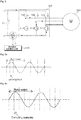
FIG. 6a illustrates a case where the rotor speed of themotor 230 and a sampling time when a phase current through the dc stage resistance element Rs is detected are not synchronized. - An error is generated in an output voltage applied to the
motor 230 because theinverter control unit 430 performs control based on an inaccurate phase current. Accordingly, the torque ripple of themotor 230 is increased. -
FIG. 6b illustrates a case where the rotor speed of themotor 230 and a sampling time when a phase current through the dc stage resistance element Rs is detected are synchronized. - This drawing illustrates that a sampling frequency when a phase current is detected is six times the frequency of a voltage applied to the
motor 230 or the rotating frequency of themotor 230. - As described above, the frequency of a voltage applied to the
motor 230 or the rotating frequency of themotor 230 and the sampling frequency of a phase current sampled through the dc stage resistance element Rs are synchronized, and theinverter control unit 430 performs control based on a detected phase current. Accordingly, an error in an output voltage applied to themotor 230 is minimized, and thus the torque ripple of themotor 230 is significantly reduced. -
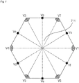
FIG. 7 is a diagram showing regions where a phase current may be detected using the one dc stage resistance element Rs based on a spatial voltage vector. - Referring to the drawing, a phase current may be detected using the one dc stage resistance element Rs in a
region 711 other than deviant crease line regions, that is, regions around VI, V2, V3, V3, V4, V5, and V6. - Meanwhile, the drawing illustrates that phase currents may be detected using the one dc stage resistance element Rs in accordance with Va, Vb, Vc, Vd, Ve, and Vf vectors in order to detect the phase current.
-
FIG. 8 is a diagram to which reference is made to describe the one pulse driving method. - If the rotation speed of the
motor 230 is several thousands of rpm or more as described above, a counter electromotive force generated in themotor 230 may increase according to a pulse width modulation (PWM) method. - Furthermore, as the rotation speed of the
motor 230 increases, the switching frequency of theinverter 420 also needs to increase. However, the PWM method is not suitable for high-speed driving because the switching frequency has an upper limit. - Accordingly, in the present invention, the
inverter 420 is controlled according to the one-pulse driving method. - That is, the
inverter control unit 430 may control the frequency of a voltage applied to the motor or the rotating frequency of the motor and the switching frequency of theinverter 420 so that they are the same. - The drawing illustrates that when the
motor 230 rotates at a high speed, the terminal voltage frequency and phase voltage frequency of themotor 230 are the same in accordance with the rotating frequency of themotor 230. - As described above, when the
motor 230 is rotated once, one pulse is applied, which is called a 1-pulse method. - Meanwhile, the drawing illustrates that when the
motor 230 is rotated once, a phase current is sampled four times when it is detected, but the above synchronization is sufficient. -
FIG. 9 is a diagram illustrating a compensation method for a detected phase current. - Referring to the drawing, the
inverter control unit 430 may include acurrent compensation unit 320, a currentinstruction generation unit 330, a voltageinstruction generation unit 340, and a switching controlsignal output unit 360. - The
current compensation unit 320 may include afirst compensation unit 320a compensating for the sampling time of a sampled phase current and asecond compensation unit 320b compensating for the sampling value of a sampled phase current. - A sampling time error may occur by sampling a phase current at Ts+tm1 and Ts-tm2, that is, points on both sides of a switching point Ts, in order to measure two phase currents as in
FIG. 9(a) . That is, the sampling time error may occur because three phase currents are not measured at the same time. - The
first compensation unit 320a may compensate for such a sampling time. - In a sampling value error, the instantaneous output voltage vector of the
inverter 420 may look rotating π/3 clockwise on an actual d-q rotor reference coordinate system during π/3 in which the output voltage Vdqss of theinverter 420 is maintained as inFIG. 9(b) . - A current value sampled at a switching point may be a peak value not an average value of a pulsating current. It is necessary to compensate a measured peak current based on an average value.
- That is, the
second compensation unit 320b may compensate for a sampling current error attributable to a d-q-axis current that pulsates between points Ts. -
FIG. 10 is a diagram to which reference is made to describe instantaneous torque control. - Referring to the drawing, the
inverter control unit 430 may generate the inverter switching control signal Sic in response to the generation of a current instruction and voltage instruction withinFIG. 3 based on a sampled phase current every sampling timing Ts(n-1), Ts(n), Ts(n+1), Ts(n+2), and may perform control so that the generated inverter switching control signal Sic is incorporated in a next control cycle. - Accordingly, the
inverter control unit 430 can perform instantaneous torque control. Accordingly, a transient response characteristic of themotor 230 can be improved. -
FIG. 11 is a perspective view showing a cleaner, that is, an example of a home appliance according to an embodiment of the present invention.FIG. 12 is a diagram showing that a second cleaner has been attached to the first cleaner ofFIG. 11 . - Referring to the drawings, the cleaner 1100 related to the present invention is a cordless separation type cleaner.
- Accordingly, the cordless
separation type cleaner 1100 may include asecond cleaner 200 detachable from afirst cleaner 50. - The
first cleaner 50 may include amain body 120, afirst battery 230a detachable from themain body 120, and afirst motor 142a that rotates using first DC power from thefirst battery 230a in order to generate a suction force. Meanwhile, thefirst cleaner 50 may be a stick type cleaner. - The
second cleaner 200 may includecoupling units 403b and 404b attached toseating units main body 120 of thefirst cleaner 50, asecond battery 230b, and asecond motor 142b that rotates using second DC power from thesecond battery 230b in order to generate a suction force. Meanwhile, thesecond cleaner 200 may be a handy type cleaner. - The
first cleaner 50 may further include afirst handle 115a formed at the top of themain body 120 and afirst input unit 117a formed near thefirst handle 115a. - Meanwhile, a fan (not shown), a fan motor (142a of
FIG. 13 ), and a fan driving unit (not shown) that drives the fan may be included within thefirst cleaner 50. A suction force may be generated by the rotation of the fan (not shown). - A generated suction force is delivered to an
intake port 110 formed at the bottom of themain body 120. - Accordingly, the
vacuum cleaner 1100, in particular, thefirst cleaner 50 can suck a foreign substance around theintake port 110. The sucked alien substance may be stored in adust canister 140 formed in thesecond cleaner 200 and detachably attached to thesecond cleaner 200. - Meanwhile, a filter for filtering out a sucked foreign substance may be further included near the
dust canister 140. Thedust canister 140 may store a filtered-out foreign substance. - Meanwhile, the
coupling units 403b and 404b of thesecond cleaner 200 may be coupled to theseating units main body 120 of thefirst cleaner 50. - The
second cleaner 200 may further include asecond handle 115b formed at the top of a frame and asecond input unit 117b formed near thesecond handle 115b. - Meanwhile, when the
second cleaner 200 is seated in theseating units main body 120 of thefirst cleaner 50, amanipulation unit 111 formed in themain body 120 of thefirst cleaner 50 may stick out. - A user may separate the
second cleaner 200 seated in theseating units main body 120 of thefirst cleaner 50 by pressing themanipulation unit 111. -
FIG. 12 illustrates that the bottom of theintake port 110 of the cleaner 1100 has been placed on thecharger 20 in the state in which thesecond cleaner 200 has been seated in theseating units main body 120 of thefirst cleaner 50. - Although not shown in the drawing, a connection unit (not shown) may be formed at the bottom of the
intake port 110 so that DC power from acharger 20 may be supplied through a connection unit (not shown). - Meanwhile, the cleaner 1100 of the present invention is a cordless cleaner, and the
second cleaner 200 can be separated. Thefirst cleaner 50 and thesecond cleaner 200 may include thebatteries - In particular, when the
second cleaner 200 is mounted on themain body 120 and the first motor (142a ofFIG. 13 ) within thefirst cleaner 50 is rotated, thefirst motor 142a may be rotated by third DC power, that is, the sum of first DC power from thefirst battery 230a and second DC power from thesecond battery 230b. - Accordingly, a suction force of high output using the plurality of batteries can be generated.
- In particular, when the
second cleaner 200 is separated and solely driven, the second motor (142b ofFIG. 13 ) is rotated by the second DC power from thesecond battery 230b. At this time, it is preferred that the suction force of thefirst motor 142a when thesecond cleaner 200 is mounted is greater than the suction force when thesecond cleaner 200 is separated and solely driven. -
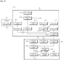
FIG. 13 is a diagram illustrating an internal block diagram of the cleaner ofFIG. 11 . - The cleaner 1100 includes a
first cleaner 50 and asecond cleaner 200. - The
first cleaner 50 may include afirst battery 230a, aconnection unit 404a that receives DC power from theconverter 410 of acharger 20, a switching unit 415ac that switches the received DC power and transfers it to afirst inverter 420a, and thefirst inverter 420a that converts the DC power from the switching unit 415ac into AC power and drives afirst motor 142a. - Meanwhile, the
first cleaner 50 may include a sensing unit that senses whether DC power is received from theconnection unit 404a or a level of received DC power and a first control unit 310a that determines whether thefirst battery 230a needs to be charged based on a sensing signal Svd1 from the sensing unit. - Meanwhile, the first control unit 310a may output a control signal sswa to the
switching unit 415a in order to charge thefirst battery 230a. - Meanwhile, the first control unit 310a may output a control signal sswab to a switching unit 415ab in order to charge the
second battery 230b. - Meanwhile, when the
second cleaner 200 is mounted, theconnection unit 403a of thefirst cleaner 50 and the connection unit 403b of thesecond cleaner 200 may be electrically connected. - Meanwhile, the first control unit 310a may receive a sensing signal Svd2 from the sensing unit that senses whether DC power is received through the
connection unit 403a or a level of DC power when thesecond cleaner 200 is mounted. - The
second cleaner 200 may include asecond battery 230b, the connection unit 403b that receives DC power from theconnection unit 403a of thefirst cleaner 50, a switching unit 415bc that switches the received DC power and transfers it to asecond inverter 420b, and thesecond inverter 420b that converts the DC power received from the switching unit 415bc into AC power and drives asecond motor 142b. - Meanwhile, the
second cleaner 200 may include asensing unit 404b that senses whether DC power is received through the connection unit 403b and a level of DC power and asecond control unit 310b that controls thesecond inverter 420b. - Meanwhile, the
second control unit 310b may output a control signal sswb to aswitching unit 415b in order to charge thesecond battery 230b. - Meanwhile, the motor driven by the motor driving apparatus described in
FIGS. 1 to 10 is a motor capable of high-speed rotation, and may be thefirst motor 142a or thesecond motor 142b ofFIG. 13 . - That is, the
motor driving apparatus 220 described inFIGS. 1 to 10 may be a driving apparatus for driving thefirst motor 142a or thesecond motor 142b ofFIG. 13 . - Meanwhile, in
FIGS. 11 to 13 , a cleaner has been illustrated as an example of another home appliance according to an embodiment of the present invention, but the present invention is not limited thereto and various examples are possible. - That is, the
motor driving apparatus 220 described inFIGS. 1 to 10 may be applied to a washing machine, a refrigerator, an air conditioner, a drone, a robot, an electric vehicle and so on. - The motor driving apparatus and the home appliance including the same according to the embodiments of the present invention are not limited and applied to the configurations and methods of the aforemtioned embodiments, but some or all of each of the embodiments may be selectively combined and configured so that the embodiments are modified in various ways
- Meanwhile, the motor driving method or the operating method of the home appliance of the present invention may be implemented in a recording medium readable by a processor included in the motor driving apparatus or the home appliance in the form of processor-readable code. The processor-readable recording medium includes all types of recording devices in which data readable by the processor is stored.
- Furthermore, although the preferred embodiments of the present invention have been illustrated and described above, the present invention is not limited to the aforementioned specific embodiments, and may be modified in various ways by a person having ordinary skill in the art to which the present invention pertains without departing from the gist of the present invention in the claims. Such modified embodiments should not be individually understood from the technical idea or prospect of this specification.
Claims (11)
- A motor driving apparatus, comprising:an inverter converting DC power of a dc stage capacitor into AC power by a switching operation and outputting the converted AC power to a motor;a dc stage resistance element disposed between the dc stage capacitor and the inverter; anda control unit controlling the inverter based on a phase current sampled through the dc stage resistance element,wherein the control unit controls a frequency of a voltage applied to the motor or a rotating frequency of the motor and a sampling frequency of the phase current sampled through the dc stage resistance element so that the frequency of the voltage or the rotating frequency of the motor and the sampling frequency of the phase current are synchronized.
- The motor driving apparatus of claim 1, wherein the control unit controls the sampling frequency so that the sampling frequency varies when the frequency of the voltage applied to the motor or the rotating frequency of the motor varies.
- The motor driving apparatus of claim 1, wherein the control unit controls the sampling frequency so that the sampling frequency is a positive number times the frequency of the voltage applied to the motor or the rotating frequency of the motor.
- The motor driving apparatus of claim 1, wherein the control unit controls the frequency of the voltage applied to the motor or the rotating frequency of the motor and the switching frequency of the inverter so that the frequency of the voltage or the rotating frequency of the motor and the sampling frequency of the phase current are identical.
- The motor driving apparatus of claim 1, wherein the control unit controls the inverter using an instantaneous torque control method.
- The motor driving apparatus of claim 1, wherein the control unit compensates for at least one of a sampling value and sampling time of the sampled phase current and outputs a switching control signal for control of the inverter based on the compensated sampling value or sampling time.
- The motor driving apparatus of claim 1, wherein the control unit comprises:a current compensation unit compensating for the sampled phase current;a current instruction generation unit generating a current instruction value based on a torque instruction value and the compensated phase current;a voltage instruction generation unit generating a voltage instruction value based on the current instruction value and the compensated phase current; anda switching control signal output unit outputting a switching control signal for driving the inverter based on the voltage instruction value.
- The motor driving apparatus of claim 7, wherein the current compensation unit comprises:a first compensation unit compensating for a sampling time of the sampled phase current; anda second compensation unit compensating for a sampling value of the sampled phase current.
- The motor driving apparatus of claim 1, further comprising:a converter converting AC power into DC power;the dc stage capacitor storing a dc stage voltage which is an output terminal of the converter; anda dc stage voltage detector detecting the dc stage voltage.
- A motor driving apparatus, comprising:an inverter converting DC power of a dc stage capacitor into AC power by a switching operation and outputting the converted AC power to a motor;a dc stage resistance element disposed between the dc stage capacitor and the inverter; anda control unit controlling the inverter based on a phase current sampled through the dc stage resistance element,wherein the control unit controls a frequency of a voltage applied to the motor or a rotating frequency of the motor and a sampling frequency of the inverter so that the frequency of the voltage or the rotating frequency of the motor and the switching frequency of the inverter are identical.
- A home appliance comprising a motor driving apparatus according to any one of claims 1 to 10.
Applications Claiming Priority (2)
| Application Number | Priority Date | Filing Date | Title |
|---|---|---|---|
| KR1020150140813A KR102493847B1 (en) | 2015-10-07 | 2015-10-07 | Motor driving apparatus and home appliance including the same |
| PCT/KR2016/011250 WO2017061817A1 (en) | 2015-10-07 | 2016-10-07 | Motor driving apparatus and home appliance comprising same |
Publications (3)
| Publication Number | Publication Date |
|---|---|
| EP3361625A1 true EP3361625A1 (en) | 2018-08-15 |
| EP3361625A4 EP3361625A4 (en) | 2019-05-22 |
| EP3361625B1 EP3361625B1 (en) | 2022-11-30 |
Family
ID=58488015
Family Applications (1)
| Application Number | Title | Priority Date | Filing Date |
|---|---|---|---|
| EP16853933.6A Active EP3361625B1 (en) | 2015-10-07 | 2016-10-07 | Motor driving apparatus and home appliance comprising same |
Country Status (4)
| Country | Link |
|---|---|
| US (1) | US10631700B2 (en) |
| EP (1) | EP3361625B1 (en) |
| KR (1) | KR102493847B1 (en) |
| WO (1) | WO2017061817A1 (en) |
Cited By (3)
| Publication number | Priority date | Publication date | Assignee | Title |
|---|---|---|---|---|
| EP3829050A1 (en) * | 2019-11-27 | 2021-06-02 | Infineon Technologies Austria AG | Speed constant control and power constant control of a permanent magnet synchronous motor |
| US11146195B2 (en) | 2019-11-27 | 2021-10-12 | Infineon Technologies Austria Ag | Fail-safe function for a permanent magnet synchronous motor |
| EP4209161A1 (en) * | 2022-01-07 | 2023-07-12 | Black & Decker Inc. | A vacuum cleaner, controller, and a method therefor |
Families Citing this family (5)
| Publication number | Priority date | Publication date | Assignee | Title |
|---|---|---|---|---|
| GB201513549D0 (en) * | 2015-07-31 | 2015-09-16 | Siemens Ag | Inverter |
| KR102320555B1 (en) | 2019-07-02 | 2021-11-01 | 엘지전자 주식회사 | Motor driving apparatus and home appliance including the same |
| KR102310342B1 (en) * | 2019-10-22 | 2021-10-07 | 엘지전자 주식회사 | Motor control apparatus and controlling method thereof |
| KR20220092095A (en) * | 2020-12-24 | 2022-07-01 | 엘지전자 주식회사 | Vacuum cleaner and controlling method thereof |
| CN113411029B (en) * | 2021-05-26 | 2022-11-01 | 无锡小天鹅电器有限公司 | Motor control method and device and electrical equipment |
Family Cites Families (17)
| Publication number | Priority date | Publication date | Assignee | Title |
|---|---|---|---|---|
| US4902944A (en) * | 1986-11-20 | 1990-02-20 | Staubli International Ag. | Digital robot control having an improved current sensing system for power amplifiers in a digital robot control |
| FR2752111B1 (en) * | 1996-07-30 | 1998-10-30 | Texas Instruments France | METHOD AND DEVICE FOR CONTROLLING INVERTERS |
| JP3346223B2 (en) * | 1997-06-10 | 2002-11-18 | 株式会社日立製作所 | Motor control method and motor control system |
| JP2000350490A (en) * | 1999-06-02 | 2000-12-15 | Matsushita Electric Ind Co Ltd | Brushless motor controller |
| JP2003204691A (en) * | 2001-10-23 | 2003-07-18 | Mitsubishi Electric Corp | Motor control device, refrigerating air conditioner, motor control method |
| US7423395B2 (en) * | 2002-07-08 | 2008-09-09 | Kabushiki Kaisha Yaskawa Denki | Sensorless vector control method for alternating-current motor and control apparatus therefor |
| KR101349851B1 (en) * | 2007-10-18 | 2014-01-09 | 엘지전자 주식회사 | Motor controller and method of controlling motor |
| JP5325561B2 (en) | 2008-12-22 | 2013-10-23 | 株式会社日立製作所 | Three-phase AC motor control device and control method thereof |
| KR101091745B1 (en) * | 2010-04-22 | 2011-12-08 | 엘지전자 주식회사 | Motor controlling apparatus and controlling method of the same |
| JP5743909B2 (en) * | 2011-01-27 | 2015-07-01 | 三菱電機株式会社 | PWM inverter driven permanent magnet type synchronous motor and control method for ventilation fan |
| US8531141B2 (en) * | 2011-02-28 | 2013-09-10 | Deere & Company | System for calibrating an electrical control system |
| ITBO20110340A1 (en) * | 2011-06-13 | 2012-12-14 | Spal Automotive Srl | ELECTRIC DRIVE |
| KR101487092B1 (en) * | 2012-07-11 | 2015-01-27 | 주식회사 엘지화학 | Pouch for secondary battery and secondary battery using the same |
| KR102010386B1 (en) * | 2013-01-09 | 2019-10-21 | 엘지전자 주식회사 | Apparatus for driving motor |
| JP5968805B2 (en) * | 2013-02-28 | 2016-08-10 | 日立オートモティブシステムズ株式会社 | Motor device and motor drive device |
| US9263982B2 (en) * | 2013-03-15 | 2016-02-16 | Steering Solutions Ip Holding Corporation | Motor control system having common-mode voltage compensation |
| JP5920300B2 (en) | 2013-09-18 | 2016-05-18 | 株式会社デンソー | Power conversion device and electric power steering device using the same |
-
2015
- 2015-10-07 KR KR1020150140813A patent/KR102493847B1/en active Active
-
2016
- 2016-10-07 US US15/766,701 patent/US10631700B2/en active Active
- 2016-10-07 WO PCT/KR2016/011250 patent/WO2017061817A1/en not_active Ceased
- 2016-10-07 EP EP16853933.6A patent/EP3361625B1/en active Active
Cited By (4)
| Publication number | Priority date | Publication date | Assignee | Title |
|---|---|---|---|---|
| EP3829050A1 (en) * | 2019-11-27 | 2021-06-02 | Infineon Technologies Austria AG | Speed constant control and power constant control of a permanent magnet synchronous motor |
| US11146195B2 (en) | 2019-11-27 | 2021-10-12 | Infineon Technologies Austria Ag | Fail-safe function for a permanent magnet synchronous motor |
| US11165381B2 (en) | 2019-11-27 | 2021-11-02 | Infineon Technologies Austria Ag | Speed contant control and power constant control of a permanent magnet synchronous motor |
| EP4209161A1 (en) * | 2022-01-07 | 2023-07-12 | Black & Decker Inc. | A vacuum cleaner, controller, and a method therefor |
Also Published As
| Publication number | Publication date |
|---|---|
| KR20170041413A (en) | 2017-04-17 |
| KR102493847B1 (en) | 2023-01-30 |
| WO2017061817A1 (en) | 2017-04-13 |
| US20180289229A1 (en) | 2018-10-11 |
| EP3361625A4 (en) | 2019-05-22 |
| US10631700B2 (en) | 2020-04-28 |
| EP3361625B1 (en) | 2022-11-30 |
Similar Documents
| Publication | Publication Date | Title |
|---|---|---|
| US10631700B2 (en) | Motor driving apparatus and home appliance comprising same | |
| JP4022630B2 (en) | Power conversion control device, power conversion control method, and program for power conversion control | |
| JP6434647B2 (en) | Motor drive, vacuum cleaner and hand dryer | |
| KR20150130993A (en) | Three phase brushless dc motor sensor-less control using sinusoidal drive method and apparatus | |
| CN108054913B (en) | PFC circuit, motor control system and inverter air conditioner | |
| CN108023474B (en) | PFC circuit, motor control system and inverter air conditioner | |
| CN108199576A (en) | Pfc circuit, electric machine control system and transducer air conditioning | |
| CN108023473A (en) | Pfc circuit, electric machine control system and transducer air conditioning | |
| JP2021141663A (en) | Drive device, drive system, and method for driving motor | |
| CN209488475U (en) | Motor control assembly and electrical equipment based on FOC | |
| CN108123593A (en) | Pfc circuit, electric machine control system and transducer air conditioning | |
| CN108054914A (en) | Pfc circuit, electric machine control system and transducer air conditioning | |
| KR102010386B1 (en) | Apparatus for driving motor | |
| CN207884487U (en) | Pfc circuit, electric machine control system and transducer air conditioning | |
| CN207884488U (en) | Pfc circuit, electric machine control system and transducer air conditioning | |
| CN103187910B (en) | Apparatus for controlling interior permanent magnet synchronous motor | |
| CN208063042U (en) | Pfc circuit, electric machine control system and transducer air conditioning | |
| CN207884485U (en) | Pfc circuit, electric machine control system and transducer air conditioning | |
| JP2003111480A (en) | Motor drive | |
| KR101804339B1 (en) | Motor driving apparatus and home appliance including the same | |
| Krishnaveni et al. | Design and implementation of low cost four switch inverter for BLDC motor drive with active power factor correction | |
| KR102068180B1 (en) | Apparatus for driving motor | |
| CN207884486U (en) | Pfc circuit, electric machine control system and transducer air conditioning | |
| KR20160007780A (en) | Motor driving apparatus, and control method for the same | |
| KR101694167B1 (en) | Method for estimating rotar position of synchronous motor and motor driver using the same |
Legal Events
| Date | Code | Title | Description |
|---|---|---|---|
| STAA | Information on the status of an ep patent application or granted ep patent |
Free format text: STATUS: THE INTERNATIONAL PUBLICATION HAS BEEN MADE |
|
| PUAI | Public reference made under article 153(3) epc to a published international application that has entered the european phase |
Free format text: ORIGINAL CODE: 0009012 |
|
| STAA | Information on the status of an ep patent application or granted ep patent |
Free format text: STATUS: REQUEST FOR EXAMINATION WAS MADE |
|
| 17P | Request for examination filed |
Effective date: 20180507 |
|
| AK | Designated contracting states |
Kind code of ref document: A1 Designated state(s): AL AT BE BG CH CY CZ DE DK EE ES FI FR GB GR HR HU IE IS IT LI LT LU LV MC MK MT NL NO PL PT RO RS SE SI SK SM TR |
|
| AX | Request for extension of the european patent |
Extension state: BA ME |
|
| DAV | Request for validation of the european patent (deleted) | ||
| DAX | Request for extension of the european patent (deleted) | ||
| A4 | Supplementary search report drawn up and despatched |
Effective date: 20190423 |
|
| RIC1 | Information provided on ipc code assigned before grant |
Ipc: H02P 27/06 20060101ALI20190415BHEP Ipc: H02P 21/24 20160101ALI20190415BHEP Ipc: H02P 21/18 20160101ALI20190415BHEP Ipc: A47L 9/28 20060101ALI20190415BHEP Ipc: H02P 21/14 20160101AFI20190415BHEP Ipc: H02P 21/00 20160101ALI20190415BHEP Ipc: H02P 21/22 20160101ALI20190415BHEP Ipc: H02P 27/08 20060101ALI20190415BHEP |
|
| STAA | Information on the status of an ep patent application or granted ep patent |
Free format text: STATUS: EXAMINATION IS IN PROGRESS |
|
| 17Q | First examination report despatched |
Effective date: 20210331 |
|
| GRAP | Despatch of communication of intention to grant a patent |
Free format text: ORIGINAL CODE: EPIDOSNIGR1 |
|
| STAA | Information on the status of an ep patent application or granted ep patent |
Free format text: STATUS: GRANT OF PATENT IS INTENDED |
|
| INTG | Intention to grant announced |
Effective date: 20220513 |
|
| GRAS | Grant fee paid |
Free format text: ORIGINAL CODE: EPIDOSNIGR3 |
|
| GRAA | (expected) grant |
Free format text: ORIGINAL CODE: 0009210 |
|
| STAA | Information on the status of an ep patent application or granted ep patent |
Free format text: STATUS: THE PATENT HAS BEEN GRANTED |
|
| AK | Designated contracting states |
Kind code of ref document: B1 Designated state(s): AL AT BE BG CH CY CZ DE DK EE ES FI FR GB GR HR HU IE IS IT LI LT LU LV MC MK MT NL NO PL PT RO RS SE SI SK SM TR |
|
| REG | Reference to a national code |
Ref country code: CH Ref legal event code: EP Ref country code: GB Ref legal event code: FG4D |
|
| REG | Reference to a national code |
Ref country code: AT Ref legal event code: REF Ref document number: 1535472 Country of ref document: AT Kind code of ref document: T Effective date: 20221215 Ref country code: DE Ref legal event code: R096 Ref document number: 602016076667 Country of ref document: DE |
|
| REG | Reference to a national code |
Ref country code: IE Ref legal event code: FG4D |
|
| REG | Reference to a national code |
Ref country code: LT Ref legal event code: MG9D |
|
| REG | Reference to a national code |
Ref country code: NL Ref legal event code: MP Effective date: 20221130 |
|
| PG25 | Lapsed in a contracting state [announced via postgrant information from national office to epo] |
Ref country code: SE Free format text: LAPSE BECAUSE OF FAILURE TO SUBMIT A TRANSLATION OF THE DESCRIPTION OR TO PAY THE FEE WITHIN THE PRESCRIBED TIME-LIMIT Effective date: 20221130 Ref country code: PT Free format text: LAPSE BECAUSE OF FAILURE TO SUBMIT A TRANSLATION OF THE DESCRIPTION OR TO PAY THE FEE WITHIN THE PRESCRIBED TIME-LIMIT Effective date: 20230331 Ref country code: NO Free format text: LAPSE BECAUSE OF FAILURE TO SUBMIT A TRANSLATION OF THE DESCRIPTION OR TO PAY THE FEE WITHIN THE PRESCRIBED TIME-LIMIT Effective date: 20230228 Ref country code: LT Free format text: LAPSE BECAUSE OF FAILURE TO SUBMIT A TRANSLATION OF THE DESCRIPTION OR TO PAY THE FEE WITHIN THE PRESCRIBED TIME-LIMIT Effective date: 20221130 Ref country code: FI Free format text: LAPSE BECAUSE OF FAILURE TO SUBMIT A TRANSLATION OF THE DESCRIPTION OR TO PAY THE FEE WITHIN THE PRESCRIBED TIME-LIMIT Effective date: 20221130 Ref country code: ES Free format text: LAPSE BECAUSE OF FAILURE TO SUBMIT A TRANSLATION OF THE DESCRIPTION OR TO PAY THE FEE WITHIN THE PRESCRIBED TIME-LIMIT Effective date: 20221130 |
|
| REG | Reference to a national code |
Ref country code: AT Ref legal event code: MK05 Ref document number: 1535472 Country of ref document: AT Kind code of ref document: T Effective date: 20221130 |
|
| PG25 | Lapsed in a contracting state [announced via postgrant information from national office to epo] |
Ref country code: RS Free format text: LAPSE BECAUSE OF FAILURE TO SUBMIT A TRANSLATION OF THE DESCRIPTION OR TO PAY THE FEE WITHIN THE PRESCRIBED TIME-LIMIT Effective date: 20221130 Ref country code: PL Free format text: LAPSE BECAUSE OF FAILURE TO SUBMIT A TRANSLATION OF THE DESCRIPTION OR TO PAY THE FEE WITHIN THE PRESCRIBED TIME-LIMIT Effective date: 20221130 Ref country code: LV Free format text: LAPSE BECAUSE OF FAILURE TO SUBMIT A TRANSLATION OF THE DESCRIPTION OR TO PAY THE FEE WITHIN THE PRESCRIBED TIME-LIMIT Effective date: 20221130 Ref country code: IS Free format text: LAPSE BECAUSE OF FAILURE TO SUBMIT A TRANSLATION OF THE DESCRIPTION OR TO PAY THE FEE WITHIN THE PRESCRIBED TIME-LIMIT Effective date: 20230330 Ref country code: HR Free format text: LAPSE BECAUSE OF FAILURE TO SUBMIT A TRANSLATION OF THE DESCRIPTION OR TO PAY THE FEE WITHIN THE PRESCRIBED TIME-LIMIT Effective date: 20221130 Ref country code: GR Free format text: LAPSE BECAUSE OF FAILURE TO SUBMIT A TRANSLATION OF THE DESCRIPTION OR TO PAY THE FEE WITHIN THE PRESCRIBED TIME-LIMIT Effective date: 20230301 |
|
| PG25 | Lapsed in a contracting state [announced via postgrant information from national office to epo] |
Ref country code: NL Free format text: LAPSE BECAUSE OF FAILURE TO SUBMIT A TRANSLATION OF THE DESCRIPTION OR TO PAY THE FEE WITHIN THE PRESCRIBED TIME-LIMIT Effective date: 20221130 |
|
| PG25 | Lapsed in a contracting state [announced via postgrant information from national office to epo] |
Ref country code: SM Free format text: LAPSE BECAUSE OF FAILURE TO SUBMIT A TRANSLATION OF THE DESCRIPTION OR TO PAY THE FEE WITHIN THE PRESCRIBED TIME-LIMIT Effective date: 20221130 Ref country code: RO Free format text: LAPSE BECAUSE OF FAILURE TO SUBMIT A TRANSLATION OF THE DESCRIPTION OR TO PAY THE FEE WITHIN THE PRESCRIBED TIME-LIMIT Effective date: 20221130 Ref country code: EE Free format text: LAPSE BECAUSE OF FAILURE TO SUBMIT A TRANSLATION OF THE DESCRIPTION OR TO PAY THE FEE WITHIN THE PRESCRIBED TIME-LIMIT Effective date: 20221130 Ref country code: DK Free format text: LAPSE BECAUSE OF FAILURE TO SUBMIT A TRANSLATION OF THE DESCRIPTION OR TO PAY THE FEE WITHIN THE PRESCRIBED TIME-LIMIT Effective date: 20221130 Ref country code: CZ Free format text: LAPSE BECAUSE OF FAILURE TO SUBMIT A TRANSLATION OF THE DESCRIPTION OR TO PAY THE FEE WITHIN THE PRESCRIBED TIME-LIMIT Effective date: 20221130 Ref country code: AT Free format text: LAPSE BECAUSE OF FAILURE TO SUBMIT A TRANSLATION OF THE DESCRIPTION OR TO PAY THE FEE WITHIN THE PRESCRIBED TIME-LIMIT Effective date: 20221130 |
|
| PG25 | Lapsed in a contracting state [announced via postgrant information from national office to epo] |
Ref country code: SK Free format text: LAPSE BECAUSE OF FAILURE TO SUBMIT A TRANSLATION OF THE DESCRIPTION OR TO PAY THE FEE WITHIN THE PRESCRIBED TIME-LIMIT Effective date: 20221130 Ref country code: AL Free format text: LAPSE BECAUSE OF FAILURE TO SUBMIT A TRANSLATION OF THE DESCRIPTION OR TO PAY THE FEE WITHIN THE PRESCRIBED TIME-LIMIT Effective date: 20221130 |
|
| REG | Reference to a national code |
Ref country code: DE Ref legal event code: R097 Ref document number: 602016076667 Country of ref document: DE |
|
| PLBE | No opposition filed within time limit |
Free format text: ORIGINAL CODE: 0009261 |
|
| STAA | Information on the status of an ep patent application or granted ep patent |
Free format text: STATUS: NO OPPOSITION FILED WITHIN TIME LIMIT |
|
| 26N | No opposition filed |
Effective date: 20230831 |
|
| PG25 | Lapsed in a contracting state [announced via postgrant information from national office to epo] |
Ref country code: SI Free format text: LAPSE BECAUSE OF FAILURE TO SUBMIT A TRANSLATION OF THE DESCRIPTION OR TO PAY THE FEE WITHIN THE PRESCRIBED TIME-LIMIT Effective date: 20221130 |
|
| PG25 | Lapsed in a contracting state [announced via postgrant information from national office to epo] |
Ref country code: IT Free format text: LAPSE BECAUSE OF FAILURE TO SUBMIT A TRANSLATION OF THE DESCRIPTION OR TO PAY THE FEE WITHIN THE PRESCRIBED TIME-LIMIT Effective date: 20221130 Ref country code: MC Free format text: LAPSE BECAUSE OF FAILURE TO SUBMIT A TRANSLATION OF THE DESCRIPTION OR TO PAY THE FEE WITHIN THE PRESCRIBED TIME-LIMIT Effective date: 20221130 |
|
| REG | Reference to a national code |
Ref country code: CH Ref legal event code: PL |
|
| REG | Reference to a national code |
Ref country code: BE Ref legal event code: MM Effective date: 20231031 |
|
| PG25 | Lapsed in a contracting state [announced via postgrant information from national office to epo] |
Ref country code: LU Free format text: LAPSE BECAUSE OF NON-PAYMENT OF DUE FEES Effective date: 20231007 |
|
| GBPC | Gb: european patent ceased through non-payment of renewal fee |
Effective date: 20231007 |
|
| PG25 | Lapsed in a contracting state [announced via postgrant information from national office to epo] |
Ref country code: LU Free format text: LAPSE BECAUSE OF NON-PAYMENT OF DUE FEES Effective date: 20231007 |
|
| PG25 | Lapsed in a contracting state [announced via postgrant information from national office to epo] |
Ref country code: GB Free format text: LAPSE BECAUSE OF NON-PAYMENT OF DUE FEES Effective date: 20231007 |
|
| PG25 | Lapsed in a contracting state [announced via postgrant information from national office to epo] |
Ref country code: CH Free format text: LAPSE BECAUSE OF NON-PAYMENT OF DUE FEES Effective date: 20231031 |
|
| PG25 | Lapsed in a contracting state [announced via postgrant information from national office to epo] |
Ref country code: GB Free format text: LAPSE BECAUSE OF NON-PAYMENT OF DUE FEES Effective date: 20231007 Ref country code: FR Free format text: LAPSE BECAUSE OF NON-PAYMENT OF DUE FEES Effective date: 20231031 Ref country code: CH Free format text: LAPSE BECAUSE OF NON-PAYMENT OF DUE FEES Effective date: 20231031 |
|
| PG25 | Lapsed in a contracting state [announced via postgrant information from national office to epo] |
Ref country code: BE Free format text: LAPSE BECAUSE OF NON-PAYMENT OF DUE FEES Effective date: 20231031 |
|
| PG25 | Lapsed in a contracting state [announced via postgrant information from national office to epo] |
Ref country code: IE Free format text: LAPSE BECAUSE OF NON-PAYMENT OF DUE FEES Effective date: 20231007 |
|
| PG25 | Lapsed in a contracting state [announced via postgrant information from national office to epo] |
Ref country code: IE Free format text: LAPSE BECAUSE OF NON-PAYMENT OF DUE FEES Effective date: 20231007 |
|
| PG25 | Lapsed in a contracting state [announced via postgrant information from national office to epo] |
Ref country code: BG Free format text: LAPSE BECAUSE OF FAILURE TO SUBMIT A TRANSLATION OF THE DESCRIPTION OR TO PAY THE FEE WITHIN THE PRESCRIBED TIME-LIMIT Effective date: 20221130 |
|
| PG25 | Lapsed in a contracting state [announced via postgrant information from national office to epo] |
Ref country code: BG Free format text: LAPSE BECAUSE OF FAILURE TO SUBMIT A TRANSLATION OF THE DESCRIPTION OR TO PAY THE FEE WITHIN THE PRESCRIBED TIME-LIMIT Effective date: 20221130 |
|
| PG25 | Lapsed in a contracting state [announced via postgrant information from national office to epo] |
Ref country code: CY Free format text: LAPSE BECAUSE OF FAILURE TO SUBMIT A TRANSLATION OF THE DESCRIPTION OR TO PAY THE FEE WITHIN THE PRESCRIBED TIME-LIMIT; INVALID AB INITIO Effective date: 20161007 |
|
| PG25 | Lapsed in a contracting state [announced via postgrant information from national office to epo] |
Ref country code: HU Free format text: LAPSE BECAUSE OF FAILURE TO SUBMIT A TRANSLATION OF THE DESCRIPTION OR TO PAY THE FEE WITHIN THE PRESCRIBED TIME-LIMIT; INVALID AB INITIO Effective date: 20161007 |
|
| PG25 | Lapsed in a contracting state [announced via postgrant information from national office to epo] |
Ref country code: TR Free format text: LAPSE BECAUSE OF FAILURE TO SUBMIT A TRANSLATION OF THE DESCRIPTION OR TO PAY THE FEE WITHIN THE PRESCRIBED TIME-LIMIT Effective date: 20221130 |
|
| PGFP | Annual fee paid to national office [announced via postgrant information from national office to epo] |
Ref country code: DE Payment date: 20250908 Year of fee payment: 10 |