EP3361613A1 - Voice coil motor - Google Patents
Voice coil motor Download PDFInfo
- Publication number
- EP3361613A1 EP3361613A1 EP18165923.6A EP18165923A EP3361613A1 EP 3361613 A1 EP3361613 A1 EP 3361613A1 EP 18165923 A EP18165923 A EP 18165923A EP 3361613 A1 EP3361613 A1 EP 3361613A1
- Authority
- EP
- European Patent Office
- Prior art keywords
- foreign object
- vcm
- housing
- base
- prevention unit
- Prior art date
- Legal status (The legal status is an assumption and is not a legal conclusion. Google has not performed a legal analysis and makes no representation as to the accuracy of the status listed.)
- Granted
Links
- 230000035515 penetration Effects 0.000 claims abstract description 66
- 230000002265 prevention Effects 0.000 claims abstract description 61
- 230000008878 coupling Effects 0.000 claims description 38
- 238000010168 coupling process Methods 0.000 claims description 38
- 238000005859 coupling reaction Methods 0.000 claims description 38
- 239000000853 adhesive Substances 0.000 claims description 5
- 230000001070 adhesive effect Effects 0.000 claims description 5
- 239000003822 epoxy resin Substances 0.000 claims description 3
- 229920000647 polyepoxide Polymers 0.000 claims description 3
- 230000004308 accommodation Effects 0.000 claims 1
- 238000000034 method Methods 0.000 description 8
- 230000006866 deterioration Effects 0.000 description 2
- 230000000694 effects Effects 0.000 description 2
- 230000000149 penetrating effect Effects 0.000 description 2
- 239000000428 dust Substances 0.000 description 1
- 238000009413 insulation Methods 0.000 description 1
- 239000002184 metal Substances 0.000 description 1
- 238000010295 mobile communication Methods 0.000 description 1
- 229920005989 resin Polymers 0.000 description 1
- 239000011347 resin Substances 0.000 description 1
- 238000004804 winding Methods 0.000 description 1
Images


Classifications
-
- H—ELECTRICITY
- H02—GENERATION; CONVERSION OR DISTRIBUTION OF ELECTRIC POWER
- H02K—DYNAMO-ELECTRIC MACHINES
- H02K33/00—Motors with reciprocating, oscillating or vibrating magnet, armature or coil system
- H02K33/18—Motors with reciprocating, oscillating or vibrating magnet, armature or coil system with coil systems moving upon intermittent or reversed energisation thereof by interaction with a fixed field system, e.g. permanent magnets
-
- H—ELECTRICITY
- H02—GENERATION; CONVERSION OR DISTRIBUTION OF ELECTRIC POWER
- H02K—DYNAMO-ELECTRIC MACHINES
- H02K5/00—Casings; Enclosures; Supports
- H02K5/04—Casings or enclosures characterised by the shape, form or construction thereof
- H02K5/10—Casings or enclosures characterised by the shape, form or construction thereof with arrangements for protection from ingress, e.g. water or fingers
-
- G—PHYSICS
- G02—OPTICS
- G02B—OPTICAL ELEMENTS, SYSTEMS OR APPARATUS
- G02B27/00—Optical systems or apparatus not provided for by any of the groups G02B1/00 - G02B26/00, G02B30/00
- G02B27/0006—Optical systems or apparatus not provided for by any of the groups G02B1/00 - G02B26/00, G02B30/00 with means to keep optical surfaces clean, e.g. by preventing or removing dirt, stains, contamination, condensation
-
- G—PHYSICS
- G02—OPTICS
- G02B—OPTICAL ELEMENTS, SYSTEMS OR APPARATUS
- G02B7/00—Mountings, adjusting means, or light-tight connections, for optical elements
- G02B7/02—Mountings, adjusting means, or light-tight connections, for optical elements for lenses
- G02B7/022—Mountings, adjusting means, or light-tight connections, for optical elements for lenses lens and mount having complementary engagement means, e.g. screw/thread
-
- G—PHYSICS
- G02—OPTICS
- G02B—OPTICAL ELEMENTS, SYSTEMS OR APPARATUS
- G02B7/00—Mountings, adjusting means, or light-tight connections, for optical elements
- G02B7/02—Mountings, adjusting means, or light-tight connections, for optical elements for lenses
- G02B7/04—Mountings, adjusting means, or light-tight connections, for optical elements for lenses with mechanism for focusing or varying magnification
- G02B7/08—Mountings, adjusting means, or light-tight connections, for optical elements for lenses with mechanism for focusing or varying magnification adapted to co-operate with a remote control mechanism
-
- G—PHYSICS
- G03—PHOTOGRAPHY; CINEMATOGRAPHY; ANALOGOUS TECHNIQUES USING WAVES OTHER THAN OPTICAL WAVES; ELECTROGRAPHY; HOLOGRAPHY
- G03B—APPARATUS OR ARRANGEMENTS FOR TAKING PHOTOGRAPHS OR FOR PROJECTING OR VIEWING THEM; APPARATUS OR ARRANGEMENTS EMPLOYING ANALOGOUS TECHNIQUES USING WAVES OTHER THAN OPTICAL WAVES; ACCESSORIES THEREFOR
- G03B13/00—Viewfinders; Focusing aids for cameras; Means for focusing for cameras; Autofocus systems for cameras
- G03B13/32—Means for focusing
- G03B13/34—Power focusing
-
- H—ELECTRICITY
- H02—GENERATION; CONVERSION OR DISTRIBUTION OF ELECTRIC POWER
- H02K—DYNAMO-ELECTRIC MACHINES
- H02K41/00—Propulsion systems in which a rigid body is moved along a path due to dynamo-electric interaction between the body and a magnetic field travelling along the path
- H02K41/02—Linear motors; Sectional motors
- H02K41/035—DC motors; Unipolar motors
- H02K41/0352—Unipolar motors
- H02K41/0354—Lorentz force motors, e.g. voice coil motors
- H02K41/0356—Lorentz force motors, e.g. voice coil motors moving along a straight path
Definitions
- a VCM Voice Coil Motor
- the VCM comprising: a rotor including a bobbin accommodated by a lens, and a coil block arranged at a periphery of the bobbin; a stator including magnets wrapping the coil block and a housing formed with an opening fixing the magnets and formed at a bottom surface with lateral surfaces formed with a first jaw preventing penetration of a foreign object; an elastic member coupled to the bobbin to elastically support the bobbin; and a base formed with lateral walls having an opening for exposing the lens and formed with a second jaw meshed with the first jaw formed at the lateral surfaces of the housing.
- the voice coil motor according to the present invention has an advantageous effect in that a first foreign object penetration prevention unit is formed at a base, and a second foreign object penetration prevention unit coupleed to the first foreign object penetration unit is formed at a distal end of a housing formed with magnets contacting a base, to prevent penetration of foreign objects into an opening of the base by passing through the base and the housing, whereby a quality deterioration of an image or of a video generated from an image sensor module can be prevented.
- a foreign object collecting member having a viscosity may be formed at an area where the housing (320) and the base (100) are meshed, to prevent a fine foreign object from introducing through a gap between the meshed housing (320) and the base (100).
- the foreign object collecting member may include an epoxy resin having a viscosity, for example.
- the foreign object collecting member may be formed between the lateral plate (370) of the yoke and the lateral surface of the base (100) coupled to the lateral plate (370).
Abstract
Description
- The present invention relates to a voice coil motor, and more particularly to a voice coil motor configured to prevent penetration of foreign objects.
- Recently, mobile communication devices and small personal computers are mounted with a camera module capable of generating a digital image or a digital video corresponding to an outside light. A camera module includes an image sensor module changing an outside light to an image and a lens focusing the outside light to the image sensor module. A conventional camera module is disadvantageously fixed by the lens and the image sensor module, and a distance between the lens and the image sensor module cannot be adjusted to make it difficult to obtain a high quality image desired by a user.
- Recently, a distance between the lens of a camera module and the image sensor can be adjusted by a VCM (Voice Coil Motor) to obtain a very high quality image from the camera module. A conventional VCM is configured in such a manner that an image sensor module is arranged at a rear surface, or a rear side of a base, and an IR (Infrared) filter is arranged at the rear surface of the base.
- However, the IR filter recently suffers from a disadvantage in that, concomitant with increased resolution of an image sensor module, quality of an image or a video generated by the image sensor module greatly deteriorates in a case a foreign object such as dust is penetrated into the IR filter.
- The present invention is directed to provide a VCM (Voice Coil Motor) configured to greatly enhance a quality of an image or a video generated from an image sensor module by preventing penetration of a foreign object introduced into an IR filter.
- In order to achieve at least the above objects, in whole or in part, and in accordance with the purpose of the disclosure, as embodied and broadly described, there is provided a VCM (Voice Coil Motor), in one general aspect of the present invention, the motor comprising: a rotor including a bobbin accommodated by a lens, and a coil block arranged at a periphery of the bobbin; a base formed with an opening for exposing a lens and a first foreign object penetration prevention unit formed along an upper edge; a stator including magnets wrapping the coil block and a housing formed with an opening for fixing the magnets and formed at a bottom surface with lateral surfaces formed with a second foreign object penetration prevention unit coupled to the first foreign object prevention unit; and an elastic member coupled to the bobbin to elastically support the bobbin.
- In another general aspect of the present invention, there is provided a VCM (Voice Coil Motor), the VCM comprising: a rotor including a bobbin accommodated by a lens, and a coil block arranged at a periphery of the bobbin; a stator including magnets wrapping the coil block and a housing formed with an opening fixing the magnets and formed at a bottom surface with lateral surfaces formed with a first jaw preventing penetration of a foreign object; an elastic member coupled to the bobbin to elastically support the bobbin; and a base formed with lateral walls having an opening for exposing the lens and formed with a second jaw meshed with the first jaw formed at the lateral surfaces of the housing.
- In still another general aspect of the present invention, there is provided a VCM (Voice Coil Motor), the VCM comprising: a rotor including a bobbin accommodated by a lens, and a coil block arranged at a periphery of the bobbin; a base formed with an opening for exposing a lens and a first foreign object prevention unit formed in a shape of a concave groove along an upper edge; a stator including magnets wrapping the coil block and a housing formed with an opening for fixing the magnets and formed at a bottom surface with lateral surfaces protrusively formed with a second foreign object penetration prevention unit coupled to the first foreign object penetration prevention unit; and an elastic member coupled to the bobbin to elastically support the bobbin.
- Technical problems to be solved by the present invention are not restricted to the above-mentioned description, and any other technical problems not mentioned so far will be clearly appreciated from the following description by skill in the art.
- The voice coil motor according to the present invention has an advantageous effect in that a first foreign object penetration prevention unit is formed at a base, and a second foreign object penetration prevention unit coupleed to the first foreign object penetration unit is formed at a distal end of a housing formed with magnets contacting a base, to prevent penetration of foreign objects into an opening of the base by passing through the base and the housing, whereby a quality deterioration of an image or of a video generated from an image sensor module can be prevented.
- Non-limiting exemplary embodiments of the present invention will be described in detail with reference to the accompanying drawings. Like reference numerals refer to like parts or portions throughout the description of several views of the drawings.
-
FIG.1 is an exploded perspective view illustrating a voice coil motor according to an exemplary embodiment of the present invention. -
FIG.2 is an assembled cross-sectional view ofFIG.1 . -
FIG.3 is an enlarged view of 'A' ofFIG. 2 . -
FIG.4 is a longitudinal cross-sectional view of a housing inFIG.1 . -
FIG.5 is a cross-sectional view illustrating a coupled structure between a housing and a base according to another exemplary embodiment of the present invention. -
FIG. 6 is a cross-sectional view illustrating a housing of a voice coil motor and a part of a base according to still another exemplary embodiment of the present invention. - The advantages, features and methods for achieving the foregoing will be apparent from the accompanying drawings and exemplary embodiments that follow. Embodiments of the present invention are described below by way of example only. These examples represent the best ways of putting the invention into practice that are currently known to the Applicant although they are not the only ways in which this could be achieved.
- Now, the present invention will be described in detail with reference to the accompanying drawings.
-
FIG.1 is an exploded perspective view illustrating a voice coil motor according to an exemplary embodiment of the present invention,FIG.2 is an assembled cross-sectional view ofFIG.1 ,FIG.3 is an enlarged view of 'A' ofFIG. 2 , andFIG.4 is a longitudinal cross-sectional view of a housing inFIG.1 .
Referring toFIG. 1 , a VCM (800, Voice Coil Motor) includes a rotor (200), a stator (300), an elastic member (400) and a base (100). In addition, the VCM (800) may further include a yoke (350) and a cover member (600). The base (100) serves to fix the rotor (200, described later), the stator, the elastic member (400) and the yoke (350). The base is formed with a form similar to a rectangular parallelepiped plate centrally formed with an opening (105), for example. The base (100) is formed at a rear surface with an IR (Infrared) filter and/or an image sensor module (not shown). The image sensor module generates a digital image or a digital video correponding to an outside light incident through the opening (105) of the base (100). Four corners of an upper surface (110) of the base (100) are formed with four coupling pillars (120) protruded to a direction perpendicular to the upper surface (110) of the base (100). - Now, referring to
FIGS. 2 and 3 , the upper surface (110) of the base (100) is formed with first foreign object penetration prevention units (130) which in turn protrude, each in the shape of a wall, along an edge of the upper surface (110) of the base (100). The first foreign object penetration prevention units (130) may be formed in the shape of connecting four coupling pillars (120), and each of the first foreign object penetration prevention units (130) may take a form of a square closed loop when viewed in a top plan view.
The first foreign object penetration prevention units (130) formed on the upper surface (110) of the base (100) are coupled to a housing of a stator (described later) to prevent foreign objects from penetrating an opening formed at the base (100). Each of the first foreign object penetration prevention units (130) formed on the upper surface (110) of the base (100) in an exemplary embodiment of the present invention may be formed with a first thickness, for example. - Referring to
FIG.1 again, the rotor (200) includes a bobbin (210) and a coil block (250). The bobbin (210) is formed in a shape of a cylinder having a through hole (212), for example, and the bobbin (210) is coupled at an inner surface thereof to a lens (215). In an exemplary embodiment of the present invention, an inner circumferential surface of the bobbin (210) and an outer circumferential surface of the lens (215) may be fixed by way of a screw fastening method. For example, the inner circumferential surface of the bobbin (210) may be formed with a female screw unit, and the outer circumferential surface of the lens (215) may be formed with a male screw unit.
The coil block (250) takes a shape of a cylinder, for example, and is formed by winding a long wire coated with an insulation resin in a shape of a cylinder. The cylindrical coil block (250) may be inserted into an outer circumferential surface of the bobbin (210), and the coil block (250) arranged at the outer circumferential surface of the bobbin (210) is attached to the outer circumferential surface of the bobbin (210) using an adhesive. Alternatively, the coil block (250) may be directly wound on the outer circumferential surface of the bobbin (210). - Both distal ends of the coil block (250) formed on the outer circumferential surface (external surface) of the bobbin (210) protrude downwards of the bobbin (210), and both distal ends of the coil block (250) protruding downwards of the bobbin (210) are electrically connected to the elastic member (400, described later).
- The stator (300) includes a magnet (310) and a housing (320). The magnet (310) is arranged opposite to the coil block (250) wound on the bobbin (210), where a plurality of magnets (310) is provided. The magnets (310) in an exemplary embodiment of the present invention includes flat magnets formed in a plate, and four magnets (310) each being formed in a perpendicular method, may be arranged opposite to the coil block (250), for example. The housing (320) serves to fix each of the magnets at a designated position. The housing (320) is formed in a shape of a rectangular parallelepiped opened at an upper surface and at a bottom surface. The housing (320) is formed at an upper surface (321) with an opening for exposing the bobbin (210) of the rotor (200). Furthermore, the housing (320) is formed at the upper surface (321) with coupling bosses (325) for fixing the elastic member (400, described later).
- The coupling bosses (325) are formed on four corners of the upper surface (321) opened in the shape of a square plate, and the coupling bosses formed at each corner are formed in a pair. Furthermore, each lateral surface (322) of the housing (320) arranged in parallel with the outer circumferential surface of the bobbin (210) and connected to the upper surface (321) is formed with a magnet accommocation hole (324) for securing the magnet (310). The magnet accommocation hole (324) may be an opening formed at each lateral surface (322) of the housing (320).
- The corner of the lateral surface (322) of the housing (320) is formed with coupling grooves (326) coupled to each coupling pillar (120) protruded from the upper surface (110) of the base (100), where the coupling pillars (120) of the base (100) and the coupling grooves (326) are coupled by being meshed together (press-fitted). Each lateral surface (322) of the housing (320) in an exemplary embodiment of the present invention is formed with a thickness thicker than a thickness of a first thickness of the first foreign object penetration prevention unit (130) protruded in a square closed loop from the upper surface (110) of the base (100).
- Referring to
FIGS. 2 and 3 , each lateral surface (322) of the housing (320) is formed with a second foreign object penetration prevention unit (323) for preventing penetration of foreign objects into the IR filter arranged at the rear surface of the base. The second foreign object penetration prevention unit (323) may be a groove formed in a jaw at a bottom surface of each lateral surface (322) of the housing (320), for example. The second foreign object penetration prevention unit (323) is formed in a shape of being meshed with the first foreign object penetration prevention unit (130) formed on the upper surface (110) of the base (100). - In order to prevent penetration of foreign objects into a gap formed between the first and second foreign object penetration prevention unit (130, 323), a foreign object penetration prevention member may be interposed between the first and second foreign object penetration prevention unit (130, 323).
The foreign object penetration prevention member in an exemplary embodiment of the present invention may include an epoxy resin having a viscosity, for example. Alternatively, the foreign object penetration prevention member may be an adhesive interposed between the first and second foreign object penetration prevention unit (130, 323). - For example, the second foreign object penetration prevention unit (323) and the first foreign object penetration prevention unit (130) formed on the upper surface (110) of the base (100) may be coupled by a half-lap joint method as shown in
FIG.3 .
A length of moving path required by foreign object to reach the opening (105) of the base (100) can be increased to thereby prevent the foreign object from being arranged on the IR filter through the opening (105) by way of the second foreign object penetration prevention unit (323) and the foreign object penetration prevention unit (130) formed on the upper surface (110) of the base (100) being meshed through the half-lap joint method. - The external surface of each lateral surface (322) at the housing (320) and an external surface of the first foreign object penetration prevention unit (130) at the base (100) are arranged on a same planar surface, while the second foreign object penetration prevention unit (323) formed at the bottom surface of each lateral surface (3220 of the housing (320) and the first foreign object penetration prevention unit (130) formed on the upper surface (110) of the base (100) are meshed in an exemplary embodiment of the present invention. Furthermore, the bottom surface of the housing (320) and the upper surface (110) of the base (100) are arranged on a same planar surface.
- The yoke (350) includes an upper plate (360) and a lateral plate (370). The yoke (350) serves to prevent leakage of magnetic field of the magnet (310) coupled to the housing (320) by covering the housing (320). The yoke (350) may be formed by press-woring a metal plate. The upper plate (360) of the yoke (350) is formed in a shape of a plate formed in parallel with the upper surface (321) of the housing (320), and the upper surface (360) is formed with an opening (362) for exposing the lens (215) coupled to the bobbin (212).
- The upper plate (360) of the yoke (350) is formed with a through hole (363) through which each of the coupling bosses (325) formed on the upper surface (321) of the housing (320), where the coupling boss (325) passes the through hole (363) formed at the upper surface (360) of the yoke (350) to protrude from the upper surface (360) of the yoke (350) at a predetermined height.
- The lateral plate (370) of the yoke (350) is extended to a direction parallel with the lateral surface (322) of the housing (320) from an edge of the upper plate (360) of the yoke (350), and coupled to a jaw formed at a lateral surface of the base (100).
- The lateral plate (370) of the yoke (350) in an exemplary embodiment of the present invention covers a border between the first foreign object penetration prevention unit (130) of the base (100) meshed with the second foreign object penetration prevention unit (323) of the housing (320) to prevent again the penetration of foreign object introduced to the IR filter through the opening (105) of the base (100).
- The elastic member (400) includes a first elastic member (401) and a second elastic member (402). The first elastic member (401) is formed in a pair, each spaced apart at a predetermined distance. Each of the first elastic members (401) includes an inner elastic member (405), an outer elastic member (403) and a connection elastic member (404). The first elastic member (401) functions to elastically support the bottom surface of the bobbin (210), and each of the pair of first elastic members (401) is electrically connected to both distal ends of the coil block (250). That is, the coil block (250) receives a driving signal such as a current using the first elastic member (401) as a medium. Each of the outer elastic members (403) at the first elastic member (401) is fixedly interposed between a distal end of the lateral surface (322) of the housing (320) and the upper surface (110) of the base (100).
- The second elastic member (402) is arranged on an upper surface of the yoke (350), and secured to an upper end of the bobbin (210). The second elastic member (402) is formed with a coupling hole (407) formed on the upper surface (321) of the housing (320) to allow each of the coupling bosses (325) having penetrated the through hole (363) of the upper surface (360) at the yoke (350) to pass therethrough.
- The cover member (600) is formed in a shape of a plate formed with an opening (610), and an upper plate (620) forming the cover member (600) is formed with a coupling groove (625) coupled to the coupling boss (325) of the housing (320) having penetrated the upper plate (360) of the yoke (350) and the elastic member (400). The coupling groove (625) in an exemplary embodiment of the present invention may be meshed (press-fitted) with the coupling boss (325), and preferably, the coupling groove (625) may be formed with an adhesive attaching the coupling boss (325) and the cover member (600).
- An edge of the upper plate (620) of the cover member (600) is formed with a lateral plate (640) contacting the elastic member (400), and the lateral plate (640) of the elastic member (400) serves to prevent the elastic member (400) and the upper plate (620) of the cover member (600) from being interfered by mutual contact.
- Although the exemplary embodiments of the present invention have explained and illustrated the coupling boss (325) of the housing (320) being coupled to the coupling groove (625) formed at the upper plate (620) of the cover member (600), the present invention is not limited thereto. For example, it may be possible to form a through hole corresponding to the coupling boss (325) of the cover member (600) at the upper plate (620) of the cover member (600), and the coupling boss (325) is coupled using the through hole of the upper plate (620). Furthermore, it may be possible to fuse the coupling boss (325) to the upper plate (620) while forming a through hole at the upper plate (620) to allow the coupling boss (325) to pass the upper plate (620).
-
FIG.5 is a cross-sectional view illustrating a coupled structure between a housing and a base according to another exemplary embodiment of the present invention. The VCM illustrated inFIG.5 is substantially same as the VCM illustrated inFIGS. 1 to 4 , except for a coupling structure between the first foreign object penetration prevention unit of the base and the first foreign object penetration prevention unit of the housing. Thus, no redundant explanation to the same configuration will be provided, and like reference numerals will be provided to like configurations. - Referring to
FIGS. 1 and5 , a distal end of the lateral surface (322) of the housing (320) of the VCM (800) is formed with a first jaw (326) preventing penetration of foreign object through the opening (105) of the base (100), and an upper end of the first foreign object penetration prevention unit (130) of the base (100) is formed with a second jaw (140) preventing penetration of foreign object through the opening (105) of the base (100). - In an exemplary embodiment of the present invention, the first jaw (326) formed at the distal end of the lateral surface (322) of the housing (320) and the second jaw formed at the upper end of the first foreign object penetration prevention unit (130) of the base (100) may be coupled by way of a half-lap joint method, for example. In order to couple the first and second jaws (326, 140) by way of half-lap joint method, the first foreign object penetration prevention unit (130) of the base (100) and the lateral surface (322) of the housing (320) may be formed with a same thickness. Furthermore, an external surface of the lateral surface (322) at the housing (320) formed with the first jaw (326) meshed by half-lap joint method to an external surface of the first foreign object penetration prevention unit (130) of the base (100) formed with the second jaw (140) may be arranged on a same planar surface.
- Meanwhile, referring to
FIG.5 , the first elastic member (401) of the elastic member (400) is interposed between the first jaw (326) formed at the lateral surface (322) of the housing (320) and the second jaw (140) formed at the distal end of the first foreign object penetration prevention unit (130) of the base (100), where the first elastic member (401) may be fixed by the first and second jaws (326, 140). -
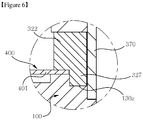
FIG. 6 is a cross-sectional view illustrating a housing of a voice coil motor and a part of a base according to still another exemplary embodiment of the present invention. - The VCM illustrated in
FIG.6 is substantially same as the VCM illustrated inFIGS. 1 to 4 , except for a coupling structure between the first foreign object penetration prevention unit of the base and the second foreign object penetration prevention unit of the housing. Thus, no redundant explanation to the same configuration will be provided, and like reference numerals will be provided to like configurations. - Referring to
FIGS.1 and6 , a bottom surface of the lateral surface (322) of the housing (320) of the VCM (800) may be formed with a lug unit (327) protruded in a wall shape along the bottom surface, and the upper surface (110) of the base (100) may be formed with a coupling groove (130a) for inserting the lug unit (327). The foreign object can be prevented from entering the IR filter arranged at the opening (105) of the base (100) by the coupling groove (130a) formed at the upper surface (110) of the base (100) and the lug unit (327) formed at the bottom surface of the lateral surface (322) of the housing (320). - As illustrated and explained through
FIGS. 1 to 6 , although the prevention of foreign object from penetrating between the housing (320) and the base (100) through the meshed coupling between the housing (320) and the base (100) is illustrated and explained inFIGS. 1 to 6 , a foreign object collecting member having a viscosity may be formed at an area where the housing (320) and the base (100) are meshed, to prevent a fine foreign object from introducing through a gap between the meshed housing (320) and the base (100). The foreign object collecting member may include an epoxy resin having a viscosity, for example. The foreign object collecting member may be formed between the lateral plate (370) of the yoke and the lateral surface of the base (100) coupled to the lateral plate (370). - Although
FIGS. 1 to 6 have illustrated and explained the prevention of foreign object from entering between the housing (320) and the base (100) by the meshed coupling between the housing (320) and the base (100), an adhesive may be formed at an area where the housing (320) and the base (100) are meshed, to prevent the fine foreign object from introducing into a gap formed between the meshed housing (320) and the base (100). - As apparent from the foregoing, the present invention has an industrial applicability in that a first foreign object penetration prevention unit is formed at a base, and a second foreign object penetration prevention unit coupled to the first foreign object penetration unit of the base is formed at a distal end of a housing mounted with a magnet, to prevent a foreign object from introducing into an opening of the base by passing through the base and the housing, whereby a quality deterioration of an image or of a video generated from an image sensor module can be prevented.
- While the present invention has been particularly shown and described with reference to exemplary embodiments thereof, the general inventive concept is not limited to the above-described embodiments. It will be understood by those of ordinary skill in the art that various changes and variations in form and details may be made therein without departing from the spirit and scope of the present invention as defined by the following claims.
Claims (15)
- A VCM (Voice Coil Motor), the VCM comprising:a bobbin (210);;a coil block (250) arranged at a periphery of the bobbin (210);a base (100) formed with an opening;a plurality of magnets (310) facing the coil block (250);a housing (320) formed with a magnet accommodation hole (324);a yoke(350) including an upper plate (360) formed with an opening (362) and a lateral plate (370) extended from the upper plate (360); andan elastic member (400) coupled to the bobbin (210) to elastically support the bobbin (210), characterized in thatthe base (100) includes a first foreign object prevention unit (130) protrusively formed along an upper edge and a coupling pillar (120) formed at a corner thereof,the housing (320) includes a second foreign object penetration prevention unit (323) concavely formed from a bottom surface thereof to be coupled to the first foreign object penetration prevention unit (130),the housing (320) includes a coupling groove (326) formed at a corner thereof and coupled with the coupling pillar (120) of the base (100).
- The VCM of claim 1, characterized in that the first foreign object penetration prevention unit (130) is protruded in the shape of a closed loop, and the second foreign object penetration prevention unit (323) is formed in the shape of a concave groove..
- The VCM of claim 1 or 2, further characterized by the foreign object penetration prevention member interposed between the first foreign object penetration prevention unit (130) and the second foreign object penetration prevention unit (323).
- The VCM of any one of claims 1 to 3, characterized in that the elastic member comprises a first elastic member (401) coupled to a lower portion of the bobbin (210) and a second elastic member (402) coupled to an upper portion of the bobbin (210).
- The VCM of any one of claims 1 to 4, characterized in that a height of the lateral surface at the housing (320) is formed with a height higher than that of the first foreign object penetration prevention unit (130), and a part of the elastic member (400) is interposed between the upper surface of the base (100) and the lateral surface of the housing (320).
- The VCM of any one of claims 1 to 5, characterized in that the lateral plate (370) of the yoke (350) covers the lateral surface of the housing (320) and the lateral wall of the base (100).
- The VCM of any one of claims 1 to 6, characterized in that a cover member (600) is coupled to the yoke (350) and formed with an opening, and the second elastic member (402) is disposed between the yoke (350) and the cover member (600).
- The VCM of any one of claims 1 to 7, characterized in that an external surface of the lateral surface at the housing (320) and an external surface of the lateral walls of the base (100) are arranged on a same planar surface.
- The VCM of any one of claims 1 to 8, characterized in that the first elastic member (401) is formed in a pair each spaced apart at a predetermined distance.
- The VCM any one of claims 1 to 9, characterized in that the lateral plate (370) of the yoke (350) covers a border between the first foreign object penetration prevention unit (130) meshed with the second foreign object penetration prevention unit (323).
- The VCM of claim 3, further characterized in that the foreign object penetration prevention member includes an epoxy resin having a viscosity or an adhesive.
- The VCM of any one of claims 1 to 11, characterized in that the housing (320) is formed at the upper surface (321) with coupling bosses (325) for fixing the elastic member (400).
- The VCM of any one of claims 1 to 12, characterized in that the coupling pillar (120) comprises four pillars disposed on four corners of the base (100), respectively, and the coupling groove (326) comprises four grooves disposed on four corners of the housing(320), respectively.
- The VCM of any one of claims 1 to 13, characterized in that the housing (320) comprises a lug unit (327) protruded from a lower surface thereof and the base (100) comprises a coupling groove (130a) coupled with the lug unit (327) of the housing (320).
- A camera module, comprising:the VCM of any one of claims 1 to 14;an image sensor disposed below the base (100);a lens (215) coupled to the bobbin (210);wherein the VCM adjusts a distance between the image sensor and the lens (215) .
Priority Applications (2)
| Application Number | Priority Date | Filing Date | Title |
|---|---|---|---|
| EP20157445.6A EP3672043B1 (en) | 2011-10-24 | 2012-10-24 | Voice coil motor |
| EP22163728.3A EP4037168A1 (en) | 2011-10-24 | 2012-10-24 | Voice coil motor |
Applications Claiming Priority (3)
| Application Number | Priority Date | Filing Date | Title |
|---|---|---|---|
| KR1020110108600A KR101892298B1 (en) | 2011-10-24 | 2011-10-24 | Voice coil motor |
| PCT/KR2012/008734 WO2013062292A1 (en) | 2011-10-24 | 2012-10-24 | Voice coil motor |
| EP12843912.2A EP2771966B1 (en) | 2011-10-24 | 2012-10-24 | Voice coil motor |
Related Parent Applications (2)
| Application Number | Title | Priority Date | Filing Date |
|---|---|---|---|
| EP12843912.2A Division-Into EP2771966B1 (en) | 2011-10-24 | 2012-10-24 | Voice coil motor |
| EP12843912.2A Division EP2771966B1 (en) | 2011-10-24 | 2012-10-24 | Voice coil motor |
Related Child Applications (3)
| Application Number | Title | Priority Date | Filing Date |
|---|---|---|---|
| EP22163728.3A Division EP4037168A1 (en) | 2011-10-24 | 2012-10-24 | Voice coil motor |
| EP20157445.6A Division EP3672043B1 (en) | 2011-10-24 | 2012-10-24 | Voice coil motor |
| EP20157445.6A Division-Into EP3672043B1 (en) | 2011-10-24 | 2012-10-24 | Voice coil motor |
Publications (2)
| Publication Number | Publication Date |
|---|---|
| EP3361613A1 true EP3361613A1 (en) | 2018-08-15 |
| EP3361613B1 EP3361613B1 (en) | 2020-04-01 |
Family
ID=48168059
Family Applications (4)
| Application Number | Title | Priority Date | Filing Date |
|---|---|---|---|
| EP20157445.6A Active EP3672043B1 (en) | 2011-10-24 | 2012-10-24 | Voice coil motor |
| EP22163728.3A Pending EP4037168A1 (en) | 2011-10-24 | 2012-10-24 | Voice coil motor |
| EP12843912.2A Active EP2771966B1 (en) | 2011-10-24 | 2012-10-24 | Voice coil motor |
| EP18165923.6A Active EP3361613B1 (en) | 2011-10-24 | 2012-10-24 | Voice coil motor |
Family Applications Before (3)
| Application Number | Title | Priority Date | Filing Date |
|---|---|---|---|
| EP20157445.6A Active EP3672043B1 (en) | 2011-10-24 | 2012-10-24 | Voice coil motor |
| EP22163728.3A Pending EP4037168A1 (en) | 2011-10-24 | 2012-10-24 | Voice coil motor |
| EP12843912.2A Active EP2771966B1 (en) | 2011-10-24 | 2012-10-24 | Voice coil motor |
Country Status (5)
| Country | Link |
|---|---|
| US (2) | US9438093B2 (en) |
| EP (4) | EP3672043B1 (en) |
| KR (1) | KR101892298B1 (en) |
| CN (2) | CN103907273B (en) |
| WO (1) | WO2013062292A1 (en) |
Families Citing this family (13)
| Publication number | Priority date | Publication date | Assignee | Title |
|---|---|---|---|---|
| KR102148988B1 (en) * | 2013-07-12 | 2020-08-27 | 엘지이노텍 주식회사 | Camera module |
| KR102117107B1 (en) | 2013-07-12 | 2020-05-29 | 엘지이노텍 주식회사 | Camera module |
| KR102214331B1 (en) * | 2013-11-05 | 2021-02-09 | 엘지이노텍 주식회사 | Camera module |
| KR102248938B1 (en) * | 2014-01-06 | 2021-05-06 | 엘지이노텍 주식회사 | Camera module |
| JP6414396B2 (en) * | 2014-06-16 | 2018-10-31 | ミツミ電機株式会社 | Lens holder driving device and camera-equipped mobile terminal |
| JP6458378B2 (en) * | 2014-07-11 | 2019-01-30 | ミツミ電機株式会社 | Lens driving device, camera module, and mobile terminal with camera |
| US9791713B2 (en) * | 2014-07-24 | 2017-10-17 | Lg Innotek Co., Ltd. | Lens moving apparatus |
| JP6583601B2 (en) * | 2014-08-06 | 2019-10-02 | ミツミ電機株式会社 | Lens holder driving device and camera-equipped mobile terminal |
| TWI617116B (en) * | 2014-10-24 | 2018-03-01 | 鴻海精密工業股份有限公司 | Voice coil motor |
| CN112492134B (en) * | 2014-12-17 | 2022-05-03 | Lg伊诺特有限公司 | Camera module |
| CN107026557B (en) * | 2016-02-01 | 2023-10-27 | 深圳市科曼医疗设备有限公司 | Voice coil motor |
| TWI726766B (en) | 2020-07-08 | 2021-05-01 | 大陽科技股份有限公司 | Camera module and electronic device |
| TWI812244B (en) * | 2022-04-13 | 2023-08-11 | 大陽科技股份有限公司 | Camera module and electronic device |
Citations (4)
| Publication number | Priority date | Publication date | Assignee | Title |
|---|---|---|---|---|
| KR20100022692A (en) * | 2008-08-20 | 2010-03-03 | 재영솔루텍 주식회사 | Device for small camera |
| KR20100106011A (en) * | 2009-03-23 | 2010-10-01 | 엘지이노텍 주식회사 | Motor for driving lens |
| US20110170204A1 (en) * | 2006-12-13 | 2011-07-14 | Lg Innotek Co., Ltd. | Lens Driving Apparatus |
| KR20110111624A (en) * | 2010-04-05 | 2011-10-12 | (주)차바이오앤디오스텍 | Lens actuator preventing particle induction and process thereof |
Family Cites Families (13)
| Publication number | Priority date | Publication date | Assignee | Title |
|---|---|---|---|---|
| CN1816764A (en) * | 2003-07-08 | 2006-08-09 | 柯尼卡美能达精密光学株式会社 | Imaging device, portable terminal using the same, and image device producing method |
| TWM290574U (en) * | 2005-12-09 | 2006-05-11 | Tricore Corp | Voice coil motor-type focusing actuator |
| JP2008122705A (en) * | 2006-11-13 | 2008-05-29 | Micro Uintekku Kk | Lens drive unit |
| KR101209956B1 (en) * | 2006-12-13 | 2012-12-07 | 엘지이노텍 주식회사 | Motor for driving lens |
| TWM325524U (en) * | 2007-03-20 | 2008-01-11 | Tricore Corp | Improvement of driving and positing assignment for focusing actuator |
| KR100976367B1 (en) * | 2008-06-24 | 2010-08-18 | 하이스트 시스템 주식회사 | Samulhamyong sambanghyang door locks |
| KR101649486B1 (en) * | 2009-03-23 | 2016-08-19 | 엘지이노텍 주식회사 | Motor for driving lens |
| KR20100121145A (en) * | 2009-05-08 | 2010-11-17 | 재영솔루텍 주식회사 | Auto focusing apparatus |
| KR20110000111A (en) * | 2009-06-26 | 2011-01-03 | 김종현 | Pull and releasable cable ties |
| KR101081630B1 (en) * | 2009-11-20 | 2011-11-09 | 엘지이노텍 주식회사 | Voice coil motor |
| KR20110058582A (en) * | 2009-11-26 | 2011-06-01 | (주)차바이오앤디오스텍 | Lens actuator for image pickup apparatus |
| KR20110008478U (en) * | 2010-02-25 | 2011-08-31 | (주)차바이오앤디오스텍 | Base for Camera Module and Lens Actuator Having Thereof |
| KR101283208B1 (en) * | 2010-12-20 | 2013-07-05 | 엘지이노텍 주식회사 | Motor for driving lens |
-
2011
- 2011-10-24 KR KR1020110108600A patent/KR101892298B1/en active IP Right Grant
-
2012
- 2012-10-24 EP EP20157445.6A patent/EP3672043B1/en active Active
- 2012-10-24 EP EP22163728.3A patent/EP4037168A1/en active Pending
- 2012-10-24 WO PCT/KR2012/008734 patent/WO2013062292A1/en active Application Filing
- 2012-10-24 CN CN201280052203.4A patent/CN103907273B/en active Active
- 2012-10-24 EP EP12843912.2A patent/EP2771966B1/en active Active
- 2012-10-24 EP EP18165923.6A patent/EP3361613B1/en active Active
- 2012-10-24 US US14/354,053 patent/US9438093B2/en active Active
- 2012-10-24 CN CN201710763238.3A patent/CN107544139B/en active Active
-
2016
- 2016-08-08 US US15/230,856 patent/US10164499B2/en active Active
Patent Citations (4)
| Publication number | Priority date | Publication date | Assignee | Title |
|---|---|---|---|---|
| US20110170204A1 (en) * | 2006-12-13 | 2011-07-14 | Lg Innotek Co., Ltd. | Lens Driving Apparatus |
| KR20100022692A (en) * | 2008-08-20 | 2010-03-03 | 재영솔루텍 주식회사 | Device for small camera |
| KR20100106011A (en) * | 2009-03-23 | 2010-10-01 | 엘지이노텍 주식회사 | Motor for driving lens |
| KR20110111624A (en) * | 2010-04-05 | 2011-10-12 | (주)차바이오앤디오스텍 | Lens actuator preventing particle induction and process thereof |
Also Published As
| Publication number | Publication date |
|---|---|
| EP3672043A1 (en) | 2020-06-24 |
| EP3672043B1 (en) | 2022-05-11 |
| US10164499B2 (en) | 2018-12-25 |
| EP2771966A4 (en) | 2016-12-14 |
| EP2771966A1 (en) | 2014-09-03 |
| US20140293464A1 (en) | 2014-10-02 |
| CN107544139B (en) | 2021-07-23 |
| US20160344252A1 (en) | 2016-11-24 |
| CN107544139A (en) | 2018-01-05 |
| CN103907273A (en) | 2014-07-02 |
| CN103907273B (en) | 2017-09-26 |
| US9438093B2 (en) | 2016-09-06 |
| WO2013062292A1 (en) | 2013-05-02 |
| EP2771966B1 (en) | 2018-05-30 |
| EP4037168A1 (en) | 2022-08-03 |
| KR101892298B1 (en) | 2018-08-27 |
| KR20130044503A (en) | 2013-05-03 |
| EP3361613B1 (en) | 2020-04-01 |
Similar Documents
| Publication | Publication Date | Title |
|---|---|---|
| US10164499B2 (en) | Voice coil motor | |
| US20230353028A1 (en) | Voice coil motor | |
| KR101776085B1 (en) | Voice coil motor | |
| KR101813282B1 (en) | Voice coil motor | |
| US8878400B2 (en) | Voice coil motor | |
| KR20140030767A (en) | Voice coil motor | |
| KR101971713B1 (en) | Voice coil motor | |
| KR102063980B1 (en) | Voice coil motor | |
| KR102203191B1 (en) | Voice coil motor | |
| KR102422824B1 (en) | Voice coil motor | |
| KR102015351B1 (en) | Voice coil motor | |
| KR101901972B1 (en) | Voice coil motor | |
| KR20210006492A (en) | Voice coil motor | |
| KR20210008119A (en) | Voice coil motor | |
| KR20200128504A (en) | Voice coil motor | |
| KR20200004902A (en) | Voice coil motor |
Legal Events
| Date | Code | Title | Description |
|---|---|---|---|
| PUAI | Public reference made under article 153(3) epc to a published international application that has entered the european phase |
Free format text: ORIGINAL CODE: 0009012 |
|
| STAA | Information on the status of an ep patent application or granted ep patent |
Free format text: STATUS: THE APPLICATION HAS BEEN PUBLISHED |
|
| AC | Divisional application: reference to earlier application |
Ref document number: 2771966 Country of ref document: EP Kind code of ref document: P |
|
| AK | Designated contracting states |
Kind code of ref document: A1 Designated state(s): AL AT BE BG CH CY CZ DE DK EE ES FI FR GB GR HR HU IE IS IT LI LT LU LV MC MK MT NL NO PL PT RO RS SE SI SK SM TR |
|
| STAA | Information on the status of an ep patent application or granted ep patent |
Free format text: STATUS: REQUEST FOR EXAMINATION WAS MADE |
|
| 17P | Request for examination filed |
Effective date: 20181221 |
|
| RBV | Designated contracting states (corrected) |
Designated state(s): AL AT BE BG CH CY CZ DE DK EE ES FI FR GB GR HR HU IE IS IT LI LT LU LV MC MK MT NL NO PL PT RO RS SE SI SK SM TR |
|
| GRAP | Despatch of communication of intention to grant a patent |
Free format text: ORIGINAL CODE: EPIDOSNIGR1 |
|
| STAA | Information on the status of an ep patent application or granted ep patent |
Free format text: STATUS: GRANT OF PATENT IS INTENDED |
|
| INTG | Intention to grant announced |
Effective date: 20191015 |
|
| GRAS | Grant fee paid |
Free format text: ORIGINAL CODE: EPIDOSNIGR3 |
|
| GRAA | (expected) grant |
Free format text: ORIGINAL CODE: 0009210 |
|
| STAA | Information on the status of an ep patent application or granted ep patent |
Free format text: STATUS: THE PATENT HAS BEEN GRANTED |
|
| AC | Divisional application: reference to earlier application |
Ref document number: 2771966 Country of ref document: EP Kind code of ref document: P |
|
| AK | Designated contracting states |
Kind code of ref document: B1 Designated state(s): AL AT BE BG CH CY CZ DE DK EE ES FI FR GB GR HR HU IE IS IT LI LT LU LV MC MK MT NL NO PL PT RO RS SE SI SK SM TR |
|
| REG | Reference to a national code |
Ref country code: GB Ref legal event code: FG4D |
|
| REG | Reference to a national code |
Ref country code: CH Ref legal event code: EP Ref country code: AT Ref legal event code: REF Ref document number: 1252651 Country of ref document: AT Kind code of ref document: T Effective date: 20200415 |
|
| REG | Reference to a national code |
Ref country code: DE Ref legal event code: R096 Ref document number: 602012069030 Country of ref document: DE |
|
| REG | Reference to a national code |
Ref country code: IE Ref legal event code: FG4D |
|
| PG25 | Lapsed in a contracting state [announced via postgrant information from national office to epo] |
Ref country code: BG Free format text: LAPSE BECAUSE OF FAILURE TO SUBMIT A TRANSLATION OF THE DESCRIPTION OR TO PAY THE FEE WITHIN THE PRESCRIBED TIME-LIMIT Effective date: 20200701 |
|
| REG | Reference to a national code |
Ref country code: NL Ref legal event code: MP Effective date: 20200401 |
|
| REG | Reference to a national code |
Ref country code: LT Ref legal event code: MG4D |
|
| PG25 | Lapsed in a contracting state [announced via postgrant information from national office to epo] |
Ref country code: CZ Free format text: LAPSE BECAUSE OF FAILURE TO SUBMIT A TRANSLATION OF THE DESCRIPTION OR TO PAY THE FEE WITHIN THE PRESCRIBED TIME-LIMIT Effective date: 20200401 Ref country code: PT Free format text: LAPSE BECAUSE OF FAILURE TO SUBMIT A TRANSLATION OF THE DESCRIPTION OR TO PAY THE FEE WITHIN THE PRESCRIBED TIME-LIMIT Effective date: 20200817 Ref country code: NL Free format text: LAPSE BECAUSE OF FAILURE TO SUBMIT A TRANSLATION OF THE DESCRIPTION OR TO PAY THE FEE WITHIN THE PRESCRIBED TIME-LIMIT Effective date: 20200401 Ref country code: LT Free format text: LAPSE BECAUSE OF FAILURE TO SUBMIT A TRANSLATION OF THE DESCRIPTION OR TO PAY THE FEE WITHIN THE PRESCRIBED TIME-LIMIT Effective date: 20200401 Ref country code: FI Free format text: LAPSE BECAUSE OF FAILURE TO SUBMIT A TRANSLATION OF THE DESCRIPTION OR TO PAY THE FEE WITHIN THE PRESCRIBED TIME-LIMIT Effective date: 20200401 Ref country code: IS Free format text: LAPSE BECAUSE OF FAILURE TO SUBMIT A TRANSLATION OF THE DESCRIPTION OR TO PAY THE FEE WITHIN THE PRESCRIBED TIME-LIMIT Effective date: 20200801 Ref country code: SE Free format text: LAPSE BECAUSE OF FAILURE TO SUBMIT A TRANSLATION OF THE DESCRIPTION OR TO PAY THE FEE WITHIN THE PRESCRIBED TIME-LIMIT Effective date: 20200401 Ref country code: NO Free format text: LAPSE BECAUSE OF FAILURE TO SUBMIT A TRANSLATION OF THE DESCRIPTION OR TO PAY THE FEE WITHIN THE PRESCRIBED TIME-LIMIT Effective date: 20200701 Ref country code: GR Free format text: LAPSE BECAUSE OF FAILURE TO SUBMIT A TRANSLATION OF THE DESCRIPTION OR TO PAY THE FEE WITHIN THE PRESCRIBED TIME-LIMIT Effective date: 20200702 |
|
| REG | Reference to a national code |
Ref country code: AT Ref legal event code: MK05 Ref document number: 1252651 Country of ref document: AT Kind code of ref document: T Effective date: 20200401 |
|
| PG25 | Lapsed in a contracting state [announced via postgrant information from national office to epo] |
Ref country code: HR Free format text: LAPSE BECAUSE OF FAILURE TO SUBMIT A TRANSLATION OF THE DESCRIPTION OR TO PAY THE FEE WITHIN THE PRESCRIBED TIME-LIMIT Effective date: 20200401 Ref country code: RS Free format text: LAPSE BECAUSE OF FAILURE TO SUBMIT A TRANSLATION OF THE DESCRIPTION OR TO PAY THE FEE WITHIN THE PRESCRIBED TIME-LIMIT Effective date: 20200401 Ref country code: LV Free format text: LAPSE BECAUSE OF FAILURE TO SUBMIT A TRANSLATION OF THE DESCRIPTION OR TO PAY THE FEE WITHIN THE PRESCRIBED TIME-LIMIT Effective date: 20200401 |
|
| PG25 | Lapsed in a contracting state [announced via postgrant information from national office to epo] |
Ref country code: AL Free format text: LAPSE BECAUSE OF FAILURE TO SUBMIT A TRANSLATION OF THE DESCRIPTION OR TO PAY THE FEE WITHIN THE PRESCRIBED TIME-LIMIT Effective date: 20200401 |
|
| REG | Reference to a national code |
Ref country code: DE Ref legal event code: R097 Ref document number: 602012069030 Country of ref document: DE |
|
| PG25 | Lapsed in a contracting state [announced via postgrant information from national office to epo] |
Ref country code: EE Free format text: LAPSE BECAUSE OF FAILURE TO SUBMIT A TRANSLATION OF THE DESCRIPTION OR TO PAY THE FEE WITHIN THE PRESCRIBED TIME-LIMIT Effective date: 20200401 Ref country code: AT Free format text: LAPSE BECAUSE OF FAILURE TO SUBMIT A TRANSLATION OF THE DESCRIPTION OR TO PAY THE FEE WITHIN THE PRESCRIBED TIME-LIMIT Effective date: 20200401 Ref country code: SM Free format text: LAPSE BECAUSE OF FAILURE TO SUBMIT A TRANSLATION OF THE DESCRIPTION OR TO PAY THE FEE WITHIN THE PRESCRIBED TIME-LIMIT Effective date: 20200401 Ref country code: DK Free format text: LAPSE BECAUSE OF FAILURE TO SUBMIT A TRANSLATION OF THE DESCRIPTION OR TO PAY THE FEE WITHIN THE PRESCRIBED TIME-LIMIT Effective date: 20200401 Ref country code: ES Free format text: LAPSE BECAUSE OF FAILURE TO SUBMIT A TRANSLATION OF THE DESCRIPTION OR TO PAY THE FEE WITHIN THE PRESCRIBED TIME-LIMIT Effective date: 20200401 Ref country code: RO Free format text: LAPSE BECAUSE OF FAILURE TO SUBMIT A TRANSLATION OF THE DESCRIPTION OR TO PAY THE FEE WITHIN THE PRESCRIBED TIME-LIMIT Effective date: 20200401 Ref country code: IT Free format text: LAPSE BECAUSE OF FAILURE TO SUBMIT A TRANSLATION OF THE DESCRIPTION OR TO PAY THE FEE WITHIN THE PRESCRIBED TIME-LIMIT Effective date: 20200401 |
|
| PLBE | No opposition filed within time limit |
Free format text: ORIGINAL CODE: 0009261 |
|
| STAA | Information on the status of an ep patent application or granted ep patent |
Free format text: STATUS: NO OPPOSITION FILED WITHIN TIME LIMIT |
|
| PG25 | Lapsed in a contracting state [announced via postgrant information from national office to epo] |
Ref country code: PL Free format text: LAPSE BECAUSE OF FAILURE TO SUBMIT A TRANSLATION OF THE DESCRIPTION OR TO PAY THE FEE WITHIN THE PRESCRIBED TIME-LIMIT Effective date: 20200401 Ref country code: SK Free format text: LAPSE BECAUSE OF FAILURE TO SUBMIT A TRANSLATION OF THE DESCRIPTION OR TO PAY THE FEE WITHIN THE PRESCRIBED TIME-LIMIT Effective date: 20200401 |
|
| 26N | No opposition filed |
Effective date: 20210112 |
|
| PG25 | Lapsed in a contracting state [announced via postgrant information from national office to epo] |
Ref country code: SI Free format text: LAPSE BECAUSE OF FAILURE TO SUBMIT A TRANSLATION OF THE DESCRIPTION OR TO PAY THE FEE WITHIN THE PRESCRIBED TIME-LIMIT Effective date: 20200401 |
|
| REG | Reference to a national code |
Ref country code: CH Ref legal event code: PL |
|
| PG25 | Lapsed in a contracting state [announced via postgrant information from national office to epo] |
Ref country code: MC Free format text: LAPSE BECAUSE OF FAILURE TO SUBMIT A TRANSLATION OF THE DESCRIPTION OR TO PAY THE FEE WITHIN THE PRESCRIBED TIME-LIMIT Effective date: 20200401 Ref country code: LU Free format text: LAPSE BECAUSE OF NON-PAYMENT OF DUE FEES Effective date: 20201024 |
|
| REG | Reference to a national code |
Ref country code: BE Ref legal event code: MM Effective date: 20201031 |
|
| PG25 | Lapsed in a contracting state [announced via postgrant information from national office to epo] |
Ref country code: LI Free format text: LAPSE BECAUSE OF NON-PAYMENT OF DUE FEES Effective date: 20201031 Ref country code: CH Free format text: LAPSE BECAUSE OF NON-PAYMENT OF DUE FEES Effective date: 20201031 Ref country code: BE Free format text: LAPSE BECAUSE OF NON-PAYMENT OF DUE FEES Effective date: 20201031 |
|
| PG25 | Lapsed in a contracting state [announced via postgrant information from national office to epo] |
Ref country code: IE Free format text: LAPSE BECAUSE OF NON-PAYMENT OF DUE FEES Effective date: 20201024 |
|
| PG25 | Lapsed in a contracting state [announced via postgrant information from national office to epo] |
Ref country code: TR Free format text: LAPSE BECAUSE OF FAILURE TO SUBMIT A TRANSLATION OF THE DESCRIPTION OR TO PAY THE FEE WITHIN THE PRESCRIBED TIME-LIMIT Effective date: 20200401 Ref country code: MT Free format text: LAPSE BECAUSE OF FAILURE TO SUBMIT A TRANSLATION OF THE DESCRIPTION OR TO PAY THE FEE WITHIN THE PRESCRIBED TIME-LIMIT Effective date: 20200401 Ref country code: CY Free format text: LAPSE BECAUSE OF FAILURE TO SUBMIT A TRANSLATION OF THE DESCRIPTION OR TO PAY THE FEE WITHIN THE PRESCRIBED TIME-LIMIT Effective date: 20200401 |
|
| PG25 | Lapsed in a contracting state [announced via postgrant information from national office to epo] |
Ref country code: MK Free format text: LAPSE BECAUSE OF FAILURE TO SUBMIT A TRANSLATION OF THE DESCRIPTION OR TO PAY THE FEE WITHIN THE PRESCRIBED TIME-LIMIT Effective date: 20200401 |
|
| PGFP | Annual fee paid to national office [announced via postgrant information from national office to epo] |
Ref country code: GB Payment date: 20230920 Year of fee payment: 12 |
|
| PGFP | Annual fee paid to national office [announced via postgrant information from national office to epo] |
Ref country code: FR Payment date: 20230922 Year of fee payment: 12 |
|
| PGFP | Annual fee paid to national office [announced via postgrant information from national office to epo] |
Ref country code: DE Payment date: 20230920 Year of fee payment: 12 |