EP3361580A1 - Electrical connector assembly with connection assist - Google Patents
Electrical connector assembly with connection assist Download PDFInfo
- Publication number
- EP3361580A1 EP3361580A1 EP18153568.3A EP18153568A EP3361580A1 EP 3361580 A1 EP3361580 A1 EP 3361580A1 EP 18153568 A EP18153568 A EP 18153568A EP 3361580 A1 EP3361580 A1 EP 3361580A1
- Authority
- EP
- European Patent Office
- Prior art keywords
- cam
- gear
- housing
- connector
- mate
- Prior art date
- Legal status (The legal status is an assumption and is not a legal conclusion. Google has not performed a legal analysis and makes no representation as to the accuracy of the status listed.)
- Granted
Links
Images



Classifications
-
- H—ELECTRICITY
- H01—ELECTRIC ELEMENTS
- H01R—ELECTRICALLY-CONDUCTIVE CONNECTIONS; STRUCTURAL ASSOCIATIONS OF A PLURALITY OF MUTUALLY-INSULATED ELECTRICAL CONNECTING ELEMENTS; COUPLING DEVICES; CURRENT COLLECTORS
- H01R13/00—Details of coupling devices of the kinds covered by groups H01R12/70 or H01R24/00 - H01R33/00
- H01R13/62—Means for facilitating engagement or disengagement of coupling parts or for holding them in engagement
- H01R13/629—Additional means for facilitating engagement or disengagement of coupling parts, e.g. aligning or guiding means, levers, gas pressure electrical locking indicators, manufacturing tolerances
- H01R13/62905—Additional means for facilitating engagement or disengagement of coupling parts, e.g. aligning or guiding means, levers, gas pressure electrical locking indicators, manufacturing tolerances comprising a camming member
- H01R13/62911—U-shaped sliding element
-
- H—ELECTRICITY
- H01—ELECTRIC ELEMENTS
- H01R—ELECTRICALLY-CONDUCTIVE CONNECTIONS; STRUCTURAL ASSOCIATIONS OF A PLURALITY OF MUTUALLY-INSULATED ELECTRICAL CONNECTING ELEMENTS; COUPLING DEVICES; CURRENT COLLECTORS
- H01R13/00—Details of coupling devices of the kinds covered by groups H01R12/70 or H01R24/00 - H01R33/00
- H01R13/62—Means for facilitating engagement or disengagement of coupling parts or for holding them in engagement
- H01R13/629—Additional means for facilitating engagement or disengagement of coupling parts, e.g. aligning or guiding means, levers, gas pressure electrical locking indicators, manufacturing tolerances
- H01R13/62933—Comprising exclusively pivoting lever
- H01R13/62955—Pivoting lever comprising supplementary/additional locking means
-
- H—ELECTRICITY
- H01—ELECTRIC ELEMENTS
- H01R—ELECTRICALLY-CONDUCTIVE CONNECTIONS; STRUCTURAL ASSOCIATIONS OF A PLURALITY OF MUTUALLY-INSULATED ELECTRICAL CONNECTING ELEMENTS; COUPLING DEVICES; CURRENT COLLECTORS
- H01R13/00—Details of coupling devices of the kinds covered by groups H01R12/70 or H01R24/00 - H01R33/00
- H01R13/64—Means for preventing incorrect coupling
- H01R13/641—Means for preventing incorrect coupling by indicating incorrect coupling; by indicating correct or full engagement
-
- H—ELECTRICITY
- H01—ELECTRIC ELEMENTS
- H01R—ELECTRICALLY-CONDUCTIVE CONNECTIONS; STRUCTURAL ASSOCIATIONS OF A PLURALITY OF MUTUALLY-INSULATED ELECTRICAL CONNECTING ELEMENTS; COUPLING DEVICES; CURRENT COLLECTORS
- H01R13/00—Details of coupling devices of the kinds covered by groups H01R12/70 or H01R24/00 - H01R33/00
- H01R13/62—Means for facilitating engagement or disengagement of coupling parts or for holding them in engagement
- H01R13/629—Additional means for facilitating engagement or disengagement of coupling parts, e.g. aligning or guiding means, levers, gas pressure electrical locking indicators, manufacturing tolerances
- H01R13/62905—Additional means for facilitating engagement or disengagement of coupling parts, e.g. aligning or guiding means, levers, gas pressure electrical locking indicators, manufacturing tolerances comprising a camming member
- H01R13/62916—Single camming plate
-
- H—ELECTRICITY
- H01—ELECTRIC ELEMENTS
- H01R—ELECTRICALLY-CONDUCTIVE CONNECTIONS; STRUCTURAL ASSOCIATIONS OF A PLURALITY OF MUTUALLY-INSULATED ELECTRICAL CONNECTING ELEMENTS; COUPLING DEVICES; CURRENT COLLECTORS
- H01R13/00—Details of coupling devices of the kinds covered by groups H01R12/70 or H01R24/00 - H01R33/00
- H01R13/62—Means for facilitating engagement or disengagement of coupling parts or for holding them in engagement
- H01R13/629—Additional means for facilitating engagement or disengagement of coupling parts, e.g. aligning or guiding means, levers, gas pressure electrical locking indicators, manufacturing tolerances
- H01R13/62905—Additional means for facilitating engagement or disengagement of coupling parts, e.g. aligning or guiding means, levers, gas pressure electrical locking indicators, manufacturing tolerances comprising a camming member
- H01R13/62927—Comprising supplementary or additional locking means
-
- H—ELECTRICITY
- H01—ELECTRIC ELEMENTS
- H01R—ELECTRICALLY-CONDUCTIVE CONNECTIONS; STRUCTURAL ASSOCIATIONS OF A PLURALITY OF MUTUALLY-INSULATED ELECTRICAL CONNECTING ELEMENTS; COUPLING DEVICES; CURRENT COLLECTORS
- H01R13/00—Details of coupling devices of the kinds covered by groups H01R12/70 or H01R24/00 - H01R33/00
- H01R13/62—Means for facilitating engagement or disengagement of coupling parts or for holding them in engagement
- H01R13/629—Additional means for facilitating engagement or disengagement of coupling parts, e.g. aligning or guiding means, levers, gas pressure electrical locking indicators, manufacturing tolerances
- H01R13/62933—Comprising exclusively pivoting lever
- H01R13/62938—Pivoting lever comprising own camming means
-
- H—ELECTRICITY
- H01—ELECTRIC ELEMENTS
- H01R—ELECTRICALLY-CONDUCTIVE CONNECTIONS; STRUCTURAL ASSOCIATIONS OF A PLURALITY OF MUTUALLY-INSULATED ELECTRICAL CONNECTING ELEMENTS; COUPLING DEVICES; CURRENT COLLECTORS
- H01R13/00—Details of coupling devices of the kinds covered by groups H01R12/70 or H01R24/00 - H01R33/00
- H01R13/62—Means for facilitating engagement or disengagement of coupling parts or for holding them in engagement
- H01R13/629—Additional means for facilitating engagement or disengagement of coupling parts, e.g. aligning or guiding means, levers, gas pressure electrical locking indicators, manufacturing tolerances
- H01R13/62933—Comprising exclusively pivoting lever
- H01R13/62944—Pivoting lever comprising gear teeth
-
- H—ELECTRICITY
- H01—ELECTRIC ELEMENTS
- H01R—ELECTRICALLY-CONDUCTIVE CONNECTIONS; STRUCTURAL ASSOCIATIONS OF A PLURALITY OF MUTUALLY-INSULATED ELECTRICAL CONNECTING ELEMENTS; COUPLING DEVICES; CURRENT COLLECTORS
- H01R13/00—Details of coupling devices of the kinds covered by groups H01R12/70 or H01R24/00 - H01R33/00
- H01R13/62—Means for facilitating engagement or disengagement of coupling parts or for holding them in engagement
- H01R13/629—Additional means for facilitating engagement or disengagement of coupling parts, e.g. aligning or guiding means, levers, gas pressure electrical locking indicators, manufacturing tolerances
- H01R13/62933—Comprising exclusively pivoting lever
- H01R13/6295—Pivoting lever comprising means indicating incorrect coupling of mating connectors
-
- H—ELECTRICITY
- H01—ELECTRIC ELEMENTS
- H01R—ELECTRICALLY-CONDUCTIVE CONNECTIONS; STRUCTURAL ASSOCIATIONS OF A PLURALITY OF MUTUALLY-INSULATED ELECTRICAL CONNECTING ELEMENTS; COUPLING DEVICES; CURRENT COLLECTORS
- H01R13/00—Details of coupling devices of the kinds covered by groups H01R12/70 or H01R24/00 - H01R33/00
- H01R13/62—Means for facilitating engagement or disengagement of coupling parts or for holding them in engagement
- H01R13/629—Additional means for facilitating engagement or disengagement of coupling parts, e.g. aligning or guiding means, levers, gas pressure electrical locking indicators, manufacturing tolerances
- H01R13/62933—Comprising exclusively pivoting lever
- H01R13/62966—Comprising two pivoting levers
- H01R13/62972—Wherein the pivoting levers are two lever plates
-
- H—ELECTRICITY
- H01—ELECTRIC ELEMENTS
- H01R—ELECTRICALLY-CONDUCTIVE CONNECTIONS; STRUCTURAL ASSOCIATIONS OF A PLURALITY OF MUTUALLY-INSULATED ELECTRICAL CONNECTING ELEMENTS; COUPLING DEVICES; CURRENT COLLECTORS
- H01R13/00—Details of coupling devices of the kinds covered by groups H01R12/70 or H01R24/00 - H01R33/00
- H01R13/62—Means for facilitating engagement or disengagement of coupling parts or for holding them in engagement
- H01R13/629—Additional means for facilitating engagement or disengagement of coupling parts, e.g. aligning or guiding means, levers, gas pressure electrical locking indicators, manufacturing tolerances
- H01R13/62977—Pivoting levers actuating linearly camming means
Definitions
- This disclosure generally relates to a connector, and more particularly relates to an electrical connector with a mate-assist feature.
- a connector has a first-housing having a first-outer-surface defining a guide-slot.
- the connector also includes a second-housing having a second-outer-surface.
- the second-housing is configured to mate with the first-housing, and the second-housing includes a pin extending from the second-outer-surface.
- the pin defines a cam-portion and a guide-portion, wherein the guide-portion is configured to engage the guide-slot.
- the connector also includes a mate-assist-slider moveable from an unmated-position to a mated-position.
- the mate-assist-slider is longitudinally slideably mounted to and surrounds at least a portion of the first-outer-surface.
- the mate-assist-slider also includes a gear-rack having rack-teeth.
- the connector also includes a cam-gear moveably mounted to the first-outer-surface.
- the cam-gear has gear-teeth that engage the rack-teeth such that the cam-gear moves in response to a movement of the mate-assist-slider from the unmated-position to the mated-position.
- the cam-gear defines a cam-slot for receiving the cam-portion of the pin.
- the cam-slot has an entrance having an inertial-detent that covers a portion of the guide-slot and partially blocks a travel-path of the cam-portion of the pin.
- a vibratory-feedback is provided to an assembler indicative of a properly positioned connector-housing when the pin is moved past the inertial-detent enabling the mate-assist-slider to be moved from the unmated-position to the mated-position.
- a connector in another embodiment, has a first-housing having a first-outer-surface defining a guide-slot.
- the connector also includes a second-housing having a second-outer-surface.
- the second-housing is configured to mate with the first-housing, and the second-housing includes a pin extending from the second-outer-surface.
- the pin defines a cam-portion and a guide-portion, wherein the guide-portion is configured to engage the guide-slot.
- the connector also includes a mate-assist-slider moveable from an unmated-position to a mated-position.
- the mate-assist-slider is longitudinally slideably mounted to and surrounds at least a portion of the first-outer-surface.
- the mate-assist-slider also includes a gear-rack having rack-teeth.
- the connector also includes a cam-gear moveably mounted to the first-outer-surface.
- the cam-gear has gear-teeth that engage the rack-teeth such that the cam-gear moves in response to a movement of the mate-assist-slider from the unmated-position to the mated-position.
- the cam-gear defines a cam-slot for receiving the cam-portion of the pin.
- the cam-slot has an entrance and a stop.
- the cam-gear further defines a pivot-hole configured to movably mount the cam-gear on a pivot-pin of the first-housing.
- the pivot-hole defines an opening, wherein a portion of the pivot-hole is in communication with the cam-slot.
- a connector in yet another embodiment, includes a first-housing having a first-outer-surface defining a guide-slot.
- the connector also includes a second-housing having a second-outer-surface, wherein the second-housing is configured to mate with the first-housing.
- the second-housing includes a pin extending from the second-outer-surface. The pin defines a cam-portion and a guide-portion where the guide-portion is configured to engage the guide-slot.
- the connector also includes a mate-assist-slider moveable from an unmated-position to a mated-position.
- the mate-assist-slider is longitudinally slideably mounted to and surrounds at least a portion of the first-outer-surface.
- the mate-assist-slider includes a gear-rack having rack-teeth.
- the connector also includes a cam-gear moveably mounted to the first-outer-surface.
- the cam-gear has gear-teeth that engage the rack-teeth such that the cam-gear moves in response to a movement of the mate-assist-slider from the unmated-position to the mated-position.
- the cam-gear defines a cam-slot for receiving the cam-portion of the pin.
- the cam-gear includes a locking-tab configured to prevent the movement of the cam-gear and the mate-assist-slider until an unlock-rib extending from the second-housing disengages the locking-tab as the second-housing is mated with the first-housing.
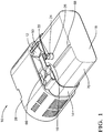
- Fig. 1 illustrates a non-limiting example of a connector 10, with a mate-assist-device.
- the connector 10 includes a first-housing 12 that has a first-outer-surface 14 that defines a guide-slot 16.
- the first-housing 12 may have multiple electrical terminals (not shown) that may attach to a wire-bundle (not shown) that may connect to wire-harness or other electrical-components.
- the first-housing 12 may also include wire seals and strain relief for the wires (not shown).
- the connector 10 also includes a second-housing 18 having a second-outer-surface 20 wherein the second-housing 18 is configured to removably mate with the first-housing 12.
- the second-housing 18 may also have multiple corresponding electrical terminals (not shown) configured to mate with the electrical terminals of the first-housing 12 that may attach to a wire-bundle that may connect to wire-harness or other electrical-components (not shown).
- the second-housing 18 may also include wire seals and strain relief for the wires, and a perimeter seal (not shown) to form a seal with the first-housing 12.
- the second-housing 18 includes a pin 22 extending from the second-outer-surface 20.
- the pin 22 defines both a cam-portion 24 and a guide-portion 26.
- the guide-portion 26 of the pin 22 is configured to engage and slide along the guide-slot 16 in the first-housing 12 to ensure that the first-housing 12 and the second-housing 18 are properly aligned prior to mating.
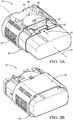
- the connector 10 also includes a mate-assist-slider 28 (see Fig. 1 ) that is moveable from an unmated-position 30 (see Fig. 2A ) to a mated-position 32 (see Fig. 2B ).
- the mate-assist-slider 28 is longitudinally slideably mounted to the first-outer-surface 14 and is configured to move in a direction parallel to a longitudinal-axis 34 of the connector 10.
- the mate-assist-slider 28 surrounds a portion of the first-outer-surface 14 and includes a gear-rack 36 having rack-teeth 38 that are configured to engage a cam-gear 40.
- the connector 10 also includes the cam-gear 40 that is rotatably mounted to the first-outer-surface 14 as illustrated in Fig. 2A .
- the cam-gear 40 has gear-teeth 42 that engage the rack-teeth 38 such that the cam-gear 40 moves in response to a movement of the mate-assist-slider 28 from the unmated-position 30 to the mated-position 32.
- the cam-gear 40 defines a cam-slot 44 (see Fig. 3A ) for receiving the cam-portion 24 of the pin 22.
- the cam-slot 44 has an entrance 46 that includes an inertial-detent 48.
- the inertial-detent 48 covers a portion of the guide-slot 16 by extending over the guide-slot 16 and partially blocks a travel-path 50 of the cam-portion 24 of the pin 22.
- a vibratory-feedback 52 is provided to an assembler that is indicative of a properly positioned connector-housing.
- the properly positioned connector-housing enables the mate-assist-slider 28 to be moved from the unmated-position 30 to the mated-position 32.
- the vibratory-feedback 52 may manifest itself as an audible and/or a tactile feedback to the assembler.
- the inertial-detent 48 may deflect by flexing the cam-gear 40 and return to a home-position (not specifically shown) as the pin 22 is moved past the inertial-detent 48 due to an external spring, or preferably through an internal spring-force resulting from the inherent flexure of the connector 10 components ( Fig. 3A ).
- the inertial-detent 48 is beneficial over the prior art ( Fig. 3B ) because the prior art requires the assembler to align the connector-housings then rotate the cam-gear 40 to capture the pin 22 in the cam-slot 44, a process that is cumbersome and ergonomically disadvantageous.
- FIG. 3A illustrates one embodiment where the gear-teeth 42 of the cam-gear 40 are aligned along a curved-path 54.
- the gear-teeth 42 may also be aligned along a straight-path 56, as illustrated in Fig. 6 .
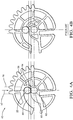
- the connector 10 may also include the cam-gear 40 wherein the cam-gear 40 further defines a stop 58 and a pivot-hole 60 ( Fig. 3A ) configured to moveably mount the cam-gear 40 on a pivot-pin 62 extending from the first-housing 12.
- the pivot-hole 60 further defines an opening 64 wherein a portion of the pivot-hole 60 is in communication with the cam-slot 44.
- Fig. 4A when the cam-gear 40 is moved the pin 22 is axially pulled to the stop 58 such that the pin 22 and the pivot-pin 62 are spaced less than 0.7 millimeters apart at the opening 64. This results in an increase of axial displacement of the mating housings by 22% over the prior art illustrated in Fig. 4B .
- the connector 10 may also include the cam-gear 40 that includes a locking-tab 66 as illustrated in Fig. 5A and Fig. 5B .
- the locking-tab 66 is configured to prevent the movement of the cam-gear 40 and the mate-assist-slider 28 until an unlock-rib 68 extending from the second-housing 18 disengages 70 the locking-tab 66 as the second-housing 18 is mated with the first-housing 12.
- the locking-tab 66 is beneficial because it enables the assembler to properly align the first-housing 12 with the second-housing 18 without moving the mate-assist-slider 28, thereby keeping the entrance 46 of the cam-slot 44 in the proper position to accept the pin 22.
- a connector 10 that includes a mate-assist feature is provided.
- the connector 10 is an improvement over prior-art-connectors because to provides the assembler with a vibratory-feedback 52 that may be tactile and/or audible and is indicative of a properly positioned connector-housing.
- the connector 10 also increases the axial displacement of the mating housings compared to prior-art-connectors.
Landscapes
- Details Of Connecting Devices For Male And Female Coupling (AREA)
Abstract
Description
- This disclosure generally relates to a connector, and more particularly relates to an electrical connector with a mate-assist feature.
- It is known to use mate-assist features on electrical connectors used in automotive applications, especially where a higher number of input/output (I/O) connections per system are required due to increased electrical content on the vehicle. Connectors utilizing an integral lever mechanism typically require pre-positioning of the connector prior to closing the lever assist mechanism. This multi-step mating process is cumbersome for assemblers, as these connection systems are not ergonomically friendly and are also prone to mating damage and/or mis-mating. Additionally, because these systems require tools and/or lever motion during mating, additional application package space is required reducing the total number of terminals possible in the connector.
- In accordance with one embodiment, a connector is provided. The connector has a first-housing having a first-outer-surface defining a guide-slot. The connector also includes a second-housing having a second-outer-surface. The second-housing is configured to mate with the first-housing, and the second-housing includes a pin extending from the second-outer-surface. The pin defines a cam-portion and a guide-portion, wherein the guide-portion is configured to engage the guide-slot. The connector also includes a mate-assist-slider moveable from an unmated-position to a mated-position. The mate-assist-slider is longitudinally slideably mounted to and surrounds at least a portion of the first-outer-surface. The mate-assist-slider also includes a gear-rack having rack-teeth. The connector also includes a cam-gear moveably mounted to the first-outer-surface. The cam-gear has gear-teeth that engage the rack-teeth such that the cam-gear moves in response to a movement of the mate-assist-slider from the unmated-position to the mated-position. The cam-gear defines a cam-slot for receiving the cam-portion of the pin. The cam-slot has an entrance having an inertial-detent that covers a portion of the guide-slot and partially blocks a travel-path of the cam-portion of the pin. A vibratory-feedback is provided to an assembler indicative of a properly positioned connector-housing when the pin is moved past the inertial-detent enabling the mate-assist-slider to be moved from the unmated-position to the mated-position.
- In another embodiment, a connector is provided. The connector has a first-housing having a first-outer-surface defining a guide-slot. The connector also includes a second-housing having a second-outer-surface. The second-housing is configured to mate with the first-housing, and the second-housing includes a pin extending from the second-outer-surface. The pin defines a cam-portion and a guide-portion, wherein the guide-portion is configured to engage the guide-slot. The connector also includes a mate-assist-slider moveable from an unmated-position to a mated-position. The mate-assist-slider is longitudinally slideably mounted to and surrounds at least a portion of the first-outer-surface. The mate-assist-slider also includes a gear-rack having rack-teeth. The connector also includes a cam-gear moveably mounted to the first-outer-surface. The cam-gear has gear-teeth that engage the rack-teeth such that the cam-gear moves in response to a movement of the mate-assist-slider from the unmated-position to the mated-position. The cam-gear defines a cam-slot for receiving the cam-portion of the pin. The cam-slot has an entrance and a stop. The cam-gear further defines a pivot-hole configured to movably mount the cam-gear on a pivot-pin of the first-housing. The pivot-hole defines an opening, wherein a portion of the pivot-hole is in communication with the cam-slot. When the mate-assist-slider is moved from the unmated-position to the mated-position the pin is axially pulled to the stop thereby mating the second-housing with the first-housing such that the pin and the pivot-pin are spaced less than 0.7 millimeters apart at the opening.
- In yet another embodiment, a connector is provided. The connector includes a first-housing having a first-outer-surface defining a guide-slot. The connector also includes a second-housing having a second-outer-surface, wherein the second-housing is configured to mate with the first-housing. The second-housing includes a pin extending from the second-outer-surface. The pin defines a cam-portion and a guide-portion where the guide-portion is configured to engage the guide-slot. The connector also includes a mate-assist-slider moveable from an unmated-position to a mated-position. The mate-assist-slider is longitudinally slideably mounted to and surrounds at least a portion of the first-outer-surface. The mate-assist-slider includes a gear-rack having rack-teeth. The connector also includes a cam-gear moveably mounted to the first-outer-surface. The cam-gear has gear-teeth that engage the rack-teeth such that the cam-gear moves in response to a movement of the mate-assist-slider from the unmated-position to the mated-position. The cam-gear defines a cam-slot for receiving the cam-portion of the pin. The cam-gear includes a locking-tab configured to prevent the movement of the cam-gear and the mate-assist-slider until an unlock-rib extending from the second-housing disengages the locking-tab as the second-housing is mated with the first-housing.
- Further features and advantages will appear more clearly on a reading of the following detailed description of the preferred embodiment, which is given by way of non-limiting example only and with reference to the accompanying drawings.
- The present invention will now be described, by way of example with reference to the accompanying drawings, in which:
-
Fig. 1 is an illustration of a connector with a mate-assist-slider in accordance with one embodiment; -
Fig. 2A is an illustration of a transparent view of the mate-assist-slider in an unmated-position of the connector ofFig. 1 in accordance with the invention; -
Fig. 2B is an illustration of the connector ofFig. 2A with the mate-assist-slider in a mated-position in accordance with the invention; -
Fig 3A is an illustration of a cam-gear in accordance with one embodiment; -
Fig 3B is an illustration of a prior-art cam-gear in accordance with the prior art; -
Fig 4A is an illustration of a cam-gear in accordance with one embodiment; -
Fig 4B is an illustration of a prior-art cam-gear in accordance with the prior art; -
Fig 5A is an illustration of a connector with a locking-tab in accordance with one embodiment; -
Fig 5B is an illustration the connector ofFig. 5A with a locking-tab in accordance with the invention; and -
Fig 6 is an illustration of a cam-gear in accordance with one embodiment. -
Fig. 1 illustrates a non-limiting example of aconnector 10, with a mate-assist-device. Theconnector 10 includes a first-housing 12 that has a first-outer-surface 14 that defines a guide-slot 16. The first-housing 12 may have multiple electrical terminals (not shown) that may attach to a wire-bundle (not shown) that may connect to wire-harness or other electrical-components. The first-housing 12 may also include wire seals and strain relief for the wires (not shown). - The
connector 10 also includes a second-housing 18 having a second-outer-surface 20 wherein the second-housing 18 is configured to removably mate with the first-housing 12. The second-housing 18 may also have multiple corresponding electrical terminals (not shown) configured to mate with the electrical terminals of the first-housing 12 that may attach to a wire-bundle that may connect to wire-harness or other electrical-components (not shown). The second-housing 18 may also include wire seals and strain relief for the wires, and a perimeter seal (not shown) to form a seal with the first-housing 12. The second-housing 18 includes apin 22 extending from the second-outer-surface 20. Thepin 22 defines both a cam-portion 24 and a guide-portion 26. The guide-portion 26 of thepin 22 is configured to engage and slide along the guide-slot 16 in the first-housing 12 to ensure that the first-housing 12 and the second-housing 18 are properly aligned prior to mating. - The
connector 10 also includes a mate-assist-slider 28 (seeFig. 1 ) that is moveable from an unmated-position 30 (seeFig. 2A ) to a mated-position 32 (seeFig. 2B ). - As illustrated in
Fig. 2A , the mate-assist-slider 28 is longitudinally slideably mounted to the first-outer-surface 14 and is configured to move in a direction parallel to a longitudinal-axis 34 of theconnector 10. The mate-assist-slider 28 surrounds a portion of the first-outer-surface 14 and includes a gear-rack 36 having rack-teeth 38 that are configured to engage a cam-gear 40. - The
connector 10 also includes the cam-gear 40 that is rotatably mounted to the first-outer-surface 14 as illustrated inFig. 2A . The cam-gear 40 has gear-teeth 42 that engage the rack-teeth 38 such that the cam-gear 40 moves in response to a movement of the mate-assist-slider 28 from the unmated-position 30 to the mated-position 32. The cam-gear 40 defines a cam-slot 44 (seeFig. 3A ) for receiving the cam-portion 24 of thepin 22. The cam-slot 44 has anentrance 46 that includes an inertial-detent 48. The inertial-detent 48 covers a portion of the guide-slot 16 by extending over the guide-slot 16 and partially blocks a travel-path 50 of the cam-portion 24 of thepin 22. When thepin 22 is moved past the inertial-detent 48 a vibratory-feedback 52 is provided to an assembler that is indicative of a properly positioned connector-housing. The properly positioned connector-housing enables the mate-assist-slider 28 to be moved from the unmated-position 30 to the mated-position 32. The vibratory-feedback 52 may manifest itself as an audible and/or a tactile feedback to the assembler. The inertial-detent 48 may deflect by flexing the cam-gear 40 and return to a home-position (not specifically shown) as thepin 22 is moved past the inertial-detent 48 due to an external spring, or preferably through an internal spring-force resulting from the inherent flexure of theconnector 10 components (Fig. 3A ). The inertial-detent 48 is beneficial over the prior art (Fig. 3B ) because the prior art requires the assembler to align the connector-housings then rotate the cam-gear 40 to capture thepin 22 in the cam-slot 44, a process that is cumbersome and ergonomically disadvantageous.Fig. 3A illustrates one embodiment where the gear-teeth 42 of the cam-gear 40 are aligned along a curved-path 54. The gear-teeth 42 may also be aligned along a straight-path 56, as illustrated inFig. 6 . - The
connector 10 may also include the cam-gear 40 wherein the cam-gear 40 further defines astop 58 and a pivot-hole 60 (Fig. 3A ) configured to moveably mount the cam-gear 40 on a pivot-pin 62 extending from the first-housing 12. The pivot-hole 60 further defines anopening 64 wherein a portion of the pivot-hole 60 is in communication with the cam-slot 44. As illustrated inFig. 4A , when the cam-gear 40 is moved thepin 22 is axially pulled to thestop 58 such that thepin 22 and the pivot-pin 62 are spaced less than 0.7 millimeters apart at theopening 64. This results in an increase of axial displacement of the mating housings by 22% over the prior art illustrated inFig. 4B . - The
connector 10 may also include the cam-gear 40 that includes a locking-tab 66 as illustrated inFig. 5A and Fig. 5B . The locking-tab 66 is configured to prevent the movement of the cam-gear 40 and the mate-assist-slider 28 until an unlock-rib 68 extending from the second-housing 18disengages 70 the locking-tab 66 as the second-housing 18 is mated with the first-housing 12. The locking-tab 66 is beneficial because it enables the assembler to properly align the first-housing 12 with the second-housing 18 without moving the mate-assist-slider 28, thereby keeping theentrance 46 of the cam-slot 44 in the proper position to accept thepin 22. - The examples presented herein are directed to electrical connector systems. However, other embodiments of the connector system may be envisioned that are adapted for use with optical cables or hybrid connections including both electrical and optical cables. Yet other embodiments of the connector system may be envisioned that are configured for connecting pneumatic or hydraulic lines.
- Accordingly, a
connector 10 that includes a mate-assist feature is provided. Theconnector 10 is an improvement over prior-art-connectors because to provides the assembler with a vibratory-feedback 52 that may be tactile and/or audible and is indicative of a properly positioned connector-housing. Theconnector 10 also increases the axial displacement of the mating housings compared to prior-art-connectors. - While this invention has been described in terms of the preferred embodiments thereof, it is not intended to be so limited, but rather only to the extent set forth in the claims that follow.
Claims (10)
- A connector (10), comprising:a first-housing (12) defining a guide-slot (16);a second-housing (18) configured to mate with the first-housing (12), said second-housing (18) including a pin (22) configured to engage the guide-slot (16);a mate-assist-slider (28) moveable from an unmated-position (30) to a mated-position (32), said mate-assist-slider (28) slideably mounted to the first-housing (12), said mate-assist-slider (28) including a gear-rack (36); anda cam-gear (40) moveably mounted to the first-housing (12), said cam-gear (40) engages the gear-rack (36) such that the cam-gear (40) moves in response to a movement of the mate-assist-slider (28), said cam-gear (40) defining a cam-slot (44) for receiving the pin (22), wherein the cam-slot (44) has an entrance (46) having an inertial-detent (48) positioned above the guide-slot (16).
- The connector (10) in accordance with claim 1, wherein a vibratory-feedback (52) is provided to an assembler when the pin (22) is moved past the inertial-detent (48) enabling the mate-assist-slider (28) to be moved from the unmated-position (30) to the mated-position (32).
- The connector (10) in accordance with any preceding claim, wherein the inertial-detent (48) deflects and returns to a home-position as the pin (22) is moved past the inertial-detent (48).
- The connector (10) in accordance with any preceding claim, wherein the gear-rack (36) has rack-teeth (38).
- The connector (10) in accordance with any preceding claim, wherein the cam-gear (40) includes gear-teeth (42) that are aligned along a curved-path (54).
- The connector (10) in accordance with any of claims 1-4, wherein the cam-gear (40) includes gear-teeth (42) that are aligned along a straight-path (56).
- The connector (10) in accordance with any preceding claim, wherein the cam-slot (44) of the cam-gear (40) further defines a stop (58), and wherein the cam-gear (40) further defines a pivot-hole (60) configured to movably mount the cam-gear (40) on a pivot-pin (62) of the first-housing (12), said pivot-hole (60) defining an opening (64) wherein a portion of the pivot-hole (60) is in communication with the cam-slot (44), and wherein when the cam-gear (40) is moved the pin (22) is axially pulled to the stop (58) such that the pin (22) and the pivot-pin (62) are spaced less than 0.7 millimeters apart at the opening (64).
- The connector (10) in accordance with any preceding claim, wherein the cam-gear (40) includes a locking-tab (66), said locking-tab (66) configured to prevent the movement of the cam-gear (40) and the mate-assist-slider (28) until an unlock-rib (68) extending from the second-housing (18) disengages (70) the locking-tab (66) as the second-housing (18) is mated with the first-housing (12).
- The connector (10) in accordance with any preceding claim, wherein the inertial-detent (48) covers a portion of the guide-slot (16) and partially blocks a travel-path (50) of the pin (22).
- The connector (10) in accordance with claim 7, wherein the cam-gear (40) includes a locking-tab (66), said locking-tab (66) configured to prevent the movement of the cam-gear (40) until an unlock-rib (68) extending from the second-housing (18) disengages (70) the locking-tab (66) as the second-housing (18) is mated with the first-housing (12).
Priority Applications (2)
| Application Number | Priority Date | Filing Date | Title |
|---|---|---|---|
| EP23176638.7A EP4235978A3 (en) | 2017-02-08 | 2018-01-26 | Electrical connector assembly with connection assist |
| EP20206075.2A EP3823106B1 (en) | 2017-02-08 | 2018-01-26 | Electrical connector assembly with connection assist |
Applications Claiming Priority (3)
| Application Number | Priority Date | Filing Date | Title |
|---|---|---|---|
| US15/427,725 US9780487B1 (en) | 2017-02-08 | 2017-02-08 | Electrical connector assembly with axial connection assist |
| US15/687,627 US9912101B1 (en) | 2017-02-08 | 2017-08-28 | Electrical connector assembly with axial connection assist |
| US15/867,326 US10109952B2 (en) | 2017-02-08 | 2018-01-10 | Electrical connector assembly with axial connection assist |
Related Child Applications (3)
| Application Number | Title | Priority Date | Filing Date |
|---|---|---|---|
| EP20206075.2A Division-Into EP3823106B1 (en) | 2017-02-08 | 2018-01-26 | Electrical connector assembly with connection assist |
| EP20206075.2A Division EP3823106B1 (en) | 2017-02-08 | 2018-01-26 | Electrical connector assembly with connection assist |
| EP23176638.7A Division EP4235978A3 (en) | 2017-02-08 | 2018-01-26 | Electrical connector assembly with connection assist |
Publications (2)
| Publication Number | Publication Date |
|---|---|
| EP3361580A1 true EP3361580A1 (en) | 2018-08-15 |
| EP3361580B1 EP3361580B1 (en) | 2021-05-19 |
Family
ID=61054199
Family Applications (3)
| Application Number | Title | Priority Date | Filing Date |
|---|---|---|---|
| EP23176638.7A Withdrawn EP4235978A3 (en) | 2017-02-08 | 2018-01-26 | Electrical connector assembly with connection assist |
| EP20206075.2A Active EP3823106B1 (en) | 2017-02-08 | 2018-01-26 | Electrical connector assembly with connection assist |
| EP18153568.3A Active EP3361580B1 (en) | 2017-02-08 | 2018-01-26 | Electrical connector assembly with connection assist |
Family Applications Before (2)
| Application Number | Title | Priority Date | Filing Date |
|---|---|---|---|
| EP23176638.7A Withdrawn EP4235978A3 (en) | 2017-02-08 | 2018-01-26 | Electrical connector assembly with connection assist |
| EP20206075.2A Active EP3823106B1 (en) | 2017-02-08 | 2018-01-26 | Electrical connector assembly with connection assist |
Country Status (2)
| Country | Link |
|---|---|
| US (1) | US10109952B2 (en) |
| EP (3) | EP4235978A3 (en) |
Cited By (1)
| Publication number | Priority date | Publication date | Assignee | Title |
|---|---|---|---|---|
| EP4550587A1 (en) * | 2023-10-31 | 2025-05-07 | Aptiv Technologies AG | Serration feature based clearance compensation mechanism for an electrical connector |
Families Citing this family (10)
| Publication number | Priority date | Publication date | Assignee | Title |
|---|---|---|---|---|
| EP3392979B1 (en) * | 2017-04-19 | 2020-01-29 | Aptiv Technologies Limited | Electrical connector with lever and methods of assembling thereof |
| EP3800746A1 (en) | 2019-10-04 | 2021-04-07 | Aptiv Technologies Limited | Right angle and straight-line connector assembly |
| EP3886266B1 (en) | 2020-03-27 | 2023-08-30 | Aptiv Technologies Limited | Electrical connector with a mate assist system |
| JP2023051001A (en) * | 2021-09-30 | 2023-04-11 | 株式会社オートネットワーク技術研究所 | Connector and connector assembly |
| JP2023050999A (en) * | 2021-09-30 | 2023-04-11 | 株式会社オートネットワーク技術研究所 | Connectors and connector assemblies |
| WO2023079496A1 (en) | 2021-11-04 | 2023-05-11 | Molex, Llc | Inline electrical connector system |
| JP2023094968A (en) * | 2021-12-24 | 2023-07-06 | 株式会社オートネットワーク技術研究所 | lever type connector |
| US12126116B2 (en) * | 2022-07-01 | 2024-10-22 | Aptiv Technologies AG | Vehicle electrical distribution center with gear driven mating assist system |
| US20240380161A1 (en) * | 2023-05-11 | 2024-11-14 | Aptiv Technologies AG | Electrical connector with ergonomic axial mating assist device |
| DE102023119847A1 (en) * | 2023-07-26 | 2025-01-30 | Amphenol-Tuchel Electronics Gesellschaft mit beschränkter Haftung | connectors with primary locking |
Citations (4)
| Publication number | Priority date | Publication date | Assignee | Title |
|---|---|---|---|---|
| EP0717466A2 (en) * | 1994-12-14 | 1996-06-19 | Sumitomo Wiring Systems, Ltd. | Connector |
| EP1180826A1 (en) * | 2000-08-11 | 2002-02-20 | Autonetworks Technologies, Ltd. | Slider-equipped connector |
| WO2013093546A1 (en) * | 2011-12-22 | 2013-06-27 | Delphi Connection Systems Holding France | Improved electrical connector assembly |
| WO2015056506A1 (en) * | 2013-10-17 | 2015-04-23 | 矢崎総業株式会社 | Lever connector |
Family Cites Families (18)
| Publication number | Priority date | Publication date | Assignee | Title |
|---|---|---|---|---|
| US3270267A (en) | 1965-07-12 | 1966-08-30 | Elton Ind Inc | Battery charging device |
| JPH03285524A (en) | 1990-03-30 | 1991-12-16 | Shinko Electric Co Ltd | Power supply for automatic charging of battery in unmanned vehicle |
| US5336934A (en) | 1992-12-17 | 1994-08-09 | Ford Motor Company | Electrical connection and interlock circuit system for vehicle electric drive |
| EP0655799B1 (en) | 1993-11-26 | 1999-10-06 | Molex Incorporated | Hooded electrical connector with terminal position assurance means |
| JPH0837057A (en) | 1994-07-25 | 1996-02-06 | Yazaki Corp | Connector engagement device |
| JP3472686B2 (en) | 1997-06-27 | 2003-12-02 | 矢崎総業株式会社 | Slide mating type connector |
| JP2975934B2 (en) * | 1997-09-26 | 1999-11-10 | 三洋電機株式会社 | Semiconductor device manufacturing method and semiconductor device |
| US5944547A (en) | 1998-03-24 | 1999-08-31 | Osram Sylvania Inc. | Connector shorting bar retention |
| US6428353B2 (en) | 2000-07-03 | 2002-08-06 | Yazaki Corporation | Connector support mechanism for interconnecting connectors |
| JP3492309B2 (en) | 2000-11-02 | 2004-02-03 | エフシーアイジャパン株式会社 | connector |
| US7744390B2 (en) | 2005-07-28 | 2010-06-29 | Fci Americas Technology, Inc. | Electrical connector assembly with connection assist |
| US7241155B2 (en) | 2005-07-28 | 2007-07-10 | Fci Americas Technology, Inc. | Electrical connector assembly with connection assist |
| JP4857048B2 (en) | 2006-08-07 | 2012-01-18 | 日本航空電子工業株式会社 | Lever type connector |
| JP4494443B2 (en) * | 2007-08-10 | 2010-06-30 | タイコエレクトロニクスジャパン合同会社 | Lever type connector |
| KR101588072B1 (en) | 2008-08-04 | 2016-01-25 | 델파이 커넥션 시스템즈 홀딩 프랑스 | Electrical connector system, an electrical device comprising the same and a method for unmating the same |
| JP5146775B2 (en) | 2009-03-04 | 2013-02-20 | 住友電装株式会社 | Lever type connector |
| JP2011253655A (en) * | 2010-06-01 | 2011-12-15 | Sumitomo Wiring Syst Ltd | Connector |
| US9780487B1 (en) | 2017-02-08 | 2017-10-03 | Delphi Technologies, Inc. | Electrical connector assembly with axial connection assist |
-
2018
- 2018-01-10 US US15/867,326 patent/US10109952B2/en active Active
- 2018-01-26 EP EP23176638.7A patent/EP4235978A3/en not_active Withdrawn
- 2018-01-26 EP EP20206075.2A patent/EP3823106B1/en active Active
- 2018-01-26 EP EP18153568.3A patent/EP3361580B1/en active Active
Patent Citations (4)
| Publication number | Priority date | Publication date | Assignee | Title |
|---|---|---|---|---|
| EP0717466A2 (en) * | 1994-12-14 | 1996-06-19 | Sumitomo Wiring Systems, Ltd. | Connector |
| EP1180826A1 (en) * | 2000-08-11 | 2002-02-20 | Autonetworks Technologies, Ltd. | Slider-equipped connector |
| WO2013093546A1 (en) * | 2011-12-22 | 2013-06-27 | Delphi Connection Systems Holding France | Improved electrical connector assembly |
| WO2015056506A1 (en) * | 2013-10-17 | 2015-04-23 | 矢崎総業株式会社 | Lever connector |
Cited By (1)
| Publication number | Priority date | Publication date | Assignee | Title |
|---|---|---|---|---|
| EP4550587A1 (en) * | 2023-10-31 | 2025-05-07 | Aptiv Technologies AG | Serration feature based clearance compensation mechanism for an electrical connector |
Also Published As
| Publication number | Publication date |
|---|---|
| EP4235978A3 (en) | 2023-09-27 |
| EP3361580B1 (en) | 2021-05-19 |
| EP3823106B1 (en) | 2023-06-28 |
| US20180226749A1 (en) | 2018-08-09 |
| US10109952B2 (en) | 2018-10-23 |
| EP4235978A2 (en) | 2023-08-30 |
| EP3823106A1 (en) | 2021-05-19 |
Similar Documents
| Publication | Publication Date | Title |
|---|---|---|
| US9780487B1 (en) | Electrical connector assembly with axial connection assist | |
| EP3361580B1 (en) | Electrical connector assembly with connection assist | |
| US9917402B1 (en) | Connector assembly with variable axial assist | |
| US9270055B2 (en) | Connector with vibratory connection feedback | |
| CN101669255B (en) | Electrical connector and connector assembly | |
| US7950942B2 (en) | Secured plug connection and method for its production | |
| US7488190B2 (en) | Lever fitting-type connector | |
| CN107069349B (en) | Electrical plug-in connection and release element therefor | |
| US9099809B2 (en) | Connection system including connector body with integral primary and secondary lock | |
| EP3410545B1 (en) | Connector assembly with variable axial assist | |
| US9401564B2 (en) | Plug-type connection with locking elements | |
| US10109950B1 (en) | High vibration connector with a connector-position-assurance device | |
| US10218122B1 (en) | Circular connector and method of retaining components | |
| US10439300B1 (en) | Connection element | |
| EP3512051A1 (en) | Connector assembly with variable axial assist | |
| US20240380161A1 (en) | Electrical connector with ergonomic axial mating assist device | |
| US10811817B1 (en) | Wire dress cover for an electrical connector | |
| CN108461963B (en) | Connector with a locking member | |
| US10720726B2 (en) | Zero insertion force power connector | |
| CN105529544B (en) | Plug-in connector | |
| CN104953334B (en) | Structures for holding electrical/electronic components with wires | |
| KR20170077045A (en) | Attached structure to automatic transmission for automobile of solenoid valve | |
| US20110028025A1 (en) | Connecting device for a multiconductor electric cable | |
| Schmidt | The flexible option | |
| JP2015225714A (en) | connector |
Legal Events
| Date | Code | Title | Description |
|---|---|---|---|
| PUAI | Public reference made under article 153(3) epc to a published international application that has entered the european phase |
Free format text: ORIGINAL CODE: 0009012 |
|
| STAA | Information on the status of an ep patent application or granted ep patent |
Free format text: STATUS: THE APPLICATION HAS BEEN PUBLISHED |
|
| AK | Designated contracting states |
Kind code of ref document: A1 Designated state(s): AL AT BE BG CH CY CZ DE DK EE ES FI FR GB GR HR HU IE IS IT LI LT LU LV MC MK MT NL NO PL PT RO RS SE SI SK SM TR |
|
| AX | Request for extension of the european patent |
Extension state: BA ME |
|
| RAP1 | Party data changed (applicant data changed or rights of an application transferred) |
Owner name: APTIV TECHNOLOGIES LIMITED |
|
| STAA | Information on the status of an ep patent application or granted ep patent |
Free format text: STATUS: REQUEST FOR EXAMINATION WAS MADE |
|
| 17P | Request for examination filed |
Effective date: 20190215 |
|
| RBV | Designated contracting states (corrected) |
Designated state(s): AL AT BE BG CH CY CZ DE DK EE ES FI FR GB GR HR HU IE IS IT LI LT LU LV MC MK MT NL NO PL PT RO RS SE SI SK SM TR |
|
| GRAP | Despatch of communication of intention to grant a patent |
Free format text: ORIGINAL CODE: EPIDOSNIGR1 |
|
| STAA | Information on the status of an ep patent application or granted ep patent |
Free format text: STATUS: GRANT OF PATENT IS INTENDED |
|
| INTG | Intention to grant announced |
Effective date: 20200724 |
|
| GRAJ | Information related to disapproval of communication of intention to grant by the applicant or resumption of examination proceedings by the epo deleted |
Free format text: ORIGINAL CODE: EPIDOSDIGR1 |
|
| STAA | Information on the status of an ep patent application or granted ep patent |
Free format text: STATUS: REQUEST FOR EXAMINATION WAS MADE |
|
| GRAS | Grant fee paid |
Free format text: ORIGINAL CODE: EPIDOSNIGR3 |
|
| STAA | Information on the status of an ep patent application or granted ep patent |
Free format text: STATUS: GRANT OF PATENT IS INTENDED |
|
| GRAP | Despatch of communication of intention to grant a patent |
Free format text: ORIGINAL CODE: EPIDOSNIGR1 |
|
| INTC | Intention to grant announced (deleted) | ||
| INTG | Intention to grant announced |
Effective date: 20201214 |
|
| GRAA | (expected) grant |
Free format text: ORIGINAL CODE: 0009210 |
|
| STAA | Information on the status of an ep patent application or granted ep patent |
Free format text: STATUS: THE PATENT HAS BEEN GRANTED |
|
| AK | Designated contracting states |
Kind code of ref document: B1 Designated state(s): AL AT BE BG CH CY CZ DE DK EE ES FI FR GB GR HR HU IE IS IT LI LT LU LV MC MK MT NL NO PL PT RO RS SE SI SK SM TR |
|
| REG | Reference to a national code |
Ref country code: GB Ref legal event code: FG4D |
|
| REG | Reference to a national code |
Ref country code: CH Ref legal event code: EP |
|
| REG | Reference to a national code |
Ref country code: DE Ref legal event code: R096 Ref document number: 602018017140 Country of ref document: DE |
|
| REG | Reference to a national code |
Ref country code: AT Ref legal event code: REF Ref document number: 1394903 Country of ref document: AT Kind code of ref document: T Effective date: 20210615 |
|
| REG | Reference to a national code |
Ref country code: IE Ref legal event code: FG4D |
|
| REG | Reference to a national code |
Ref country code: LT Ref legal event code: MG9D |
|
| REG | Reference to a national code |
Ref country code: AT Ref legal event code: MK05 Ref document number: 1394903 Country of ref document: AT Kind code of ref document: T Effective date: 20210519 |
|
| REG | Reference to a national code |
Ref country code: NL Ref legal event code: MP Effective date: 20210519 |
|
| PG25 | Lapsed in a contracting state [announced via postgrant information from national office to epo] |
Ref country code: FI Free format text: LAPSE BECAUSE OF FAILURE TO SUBMIT A TRANSLATION OF THE DESCRIPTION OR TO PAY THE FEE WITHIN THE PRESCRIBED TIME-LIMIT Effective date: 20210519 Ref country code: LT Free format text: LAPSE BECAUSE OF FAILURE TO SUBMIT A TRANSLATION OF THE DESCRIPTION OR TO PAY THE FEE WITHIN THE PRESCRIBED TIME-LIMIT Effective date: 20210519 Ref country code: HR Free format text: LAPSE BECAUSE OF FAILURE TO SUBMIT A TRANSLATION OF THE DESCRIPTION OR TO PAY THE FEE WITHIN THE PRESCRIBED TIME-LIMIT Effective date: 20210519 Ref country code: BG Free format text: LAPSE BECAUSE OF FAILURE TO SUBMIT A TRANSLATION OF THE DESCRIPTION OR TO PAY THE FEE WITHIN THE PRESCRIBED TIME-LIMIT Effective date: 20210819 Ref country code: AT Free format text: LAPSE BECAUSE OF FAILURE TO SUBMIT A TRANSLATION OF THE DESCRIPTION OR TO PAY THE FEE WITHIN THE PRESCRIBED TIME-LIMIT Effective date: 20210519 |
|
| PG25 | Lapsed in a contracting state [announced via postgrant information from national office to epo] |
Ref country code: IS Free format text: LAPSE BECAUSE OF FAILURE TO SUBMIT A TRANSLATION OF THE DESCRIPTION OR TO PAY THE FEE WITHIN THE PRESCRIBED TIME-LIMIT Effective date: 20210919 Ref country code: GR Free format text: LAPSE BECAUSE OF FAILURE TO SUBMIT A TRANSLATION OF THE DESCRIPTION OR TO PAY THE FEE WITHIN THE PRESCRIBED TIME-LIMIT Effective date: 20210820 Ref country code: PL Free format text: LAPSE BECAUSE OF FAILURE TO SUBMIT A TRANSLATION OF THE DESCRIPTION OR TO PAY THE FEE WITHIN THE PRESCRIBED TIME-LIMIT Effective date: 20210519 Ref country code: LV Free format text: LAPSE BECAUSE OF FAILURE TO SUBMIT A TRANSLATION OF THE DESCRIPTION OR TO PAY THE FEE WITHIN THE PRESCRIBED TIME-LIMIT Effective date: 20210519 Ref country code: PT Free format text: LAPSE BECAUSE OF FAILURE TO SUBMIT A TRANSLATION OF THE DESCRIPTION OR TO PAY THE FEE WITHIN THE PRESCRIBED TIME-LIMIT Effective date: 20210920 Ref country code: NO Free format text: LAPSE BECAUSE OF FAILURE TO SUBMIT A TRANSLATION OF THE DESCRIPTION OR TO PAY THE FEE WITHIN THE PRESCRIBED TIME-LIMIT Effective date: 20210819 Ref country code: SE Free format text: LAPSE BECAUSE OF FAILURE TO SUBMIT A TRANSLATION OF THE DESCRIPTION OR TO PAY THE FEE WITHIN THE PRESCRIBED TIME-LIMIT Effective date: 20210519 Ref country code: RS Free format text: LAPSE BECAUSE OF FAILURE TO SUBMIT A TRANSLATION OF THE DESCRIPTION OR TO PAY THE FEE WITHIN THE PRESCRIBED TIME-LIMIT Effective date: 20210519 |
|
| PG25 | Lapsed in a contracting state [announced via postgrant information from national office to epo] |
Ref country code: NL Free format text: LAPSE BECAUSE OF FAILURE TO SUBMIT A TRANSLATION OF THE DESCRIPTION OR TO PAY THE FEE WITHIN THE PRESCRIBED TIME-LIMIT Effective date: 20210519 |
|
| PG25 | Lapsed in a contracting state [announced via postgrant information from national office to epo] |
Ref country code: SM Free format text: LAPSE BECAUSE OF FAILURE TO SUBMIT A TRANSLATION OF THE DESCRIPTION OR TO PAY THE FEE WITHIN THE PRESCRIBED TIME-LIMIT Effective date: 20210519 Ref country code: SK Free format text: LAPSE BECAUSE OF FAILURE TO SUBMIT A TRANSLATION OF THE DESCRIPTION OR TO PAY THE FEE WITHIN THE PRESCRIBED TIME-LIMIT Effective date: 20210519 Ref country code: EE Free format text: LAPSE BECAUSE OF FAILURE TO SUBMIT A TRANSLATION OF THE DESCRIPTION OR TO PAY THE FEE WITHIN THE PRESCRIBED TIME-LIMIT Effective date: 20210519 Ref country code: ES Free format text: LAPSE BECAUSE OF FAILURE TO SUBMIT A TRANSLATION OF THE DESCRIPTION OR TO PAY THE FEE WITHIN THE PRESCRIBED TIME-LIMIT Effective date: 20210519 Ref country code: RO Free format text: LAPSE BECAUSE OF FAILURE TO SUBMIT A TRANSLATION OF THE DESCRIPTION OR TO PAY THE FEE WITHIN THE PRESCRIBED TIME-LIMIT Effective date: 20210519 Ref country code: DK Free format text: LAPSE BECAUSE OF FAILURE TO SUBMIT A TRANSLATION OF THE DESCRIPTION OR TO PAY THE FEE WITHIN THE PRESCRIBED TIME-LIMIT Effective date: 20210519 Ref country code: CZ Free format text: LAPSE BECAUSE OF FAILURE TO SUBMIT A TRANSLATION OF THE DESCRIPTION OR TO PAY THE FEE WITHIN THE PRESCRIBED TIME-LIMIT Effective date: 20210519 |
|
| REG | Reference to a national code |
Ref country code: DE Ref legal event code: R097 Ref document number: 602018017140 Country of ref document: DE |
|
| PLBE | No opposition filed within time limit |
Free format text: ORIGINAL CODE: 0009261 |
|
| STAA | Information on the status of an ep patent application or granted ep patent |
Free format text: STATUS: NO OPPOSITION FILED WITHIN TIME LIMIT |
|
| 26N | No opposition filed |
Effective date: 20220222 |
|
| PG25 | Lapsed in a contracting state [announced via postgrant information from national office to epo] |
Ref country code: IS Free format text: LAPSE BECAUSE OF FAILURE TO SUBMIT A TRANSLATION OF THE DESCRIPTION OR TO PAY THE FEE WITHIN THE PRESCRIBED TIME-LIMIT Effective date: 20210919 Ref country code: AL Free format text: LAPSE BECAUSE OF FAILURE TO SUBMIT A TRANSLATION OF THE DESCRIPTION OR TO PAY THE FEE WITHIN THE PRESCRIBED TIME-LIMIT Effective date: 20210519 |
|
| PG25 | Lapsed in a contracting state [announced via postgrant information from national office to epo] |
Ref country code: IT Free format text: LAPSE BECAUSE OF FAILURE TO SUBMIT A TRANSLATION OF THE DESCRIPTION OR TO PAY THE FEE WITHIN THE PRESCRIBED TIME-LIMIT Effective date: 20210519 |
|
| PG25 | Lapsed in a contracting state [announced via postgrant information from national office to epo] |
Ref country code: MC Free format text: LAPSE BECAUSE OF FAILURE TO SUBMIT A TRANSLATION OF THE DESCRIPTION OR TO PAY THE FEE WITHIN THE PRESCRIBED TIME-LIMIT Effective date: 20210519 |
|
| REG | Reference to a national code |
Ref country code: CH Ref legal event code: PL |
|
| REG | Reference to a national code |
Ref country code: BE Ref legal event code: MM Effective date: 20220131 |
|
| PG25 | Lapsed in a contracting state [announced via postgrant information from national office to epo] |
Ref country code: LU Free format text: LAPSE BECAUSE OF NON-PAYMENT OF DUE FEES Effective date: 20220126 |
|
| PG25 | Lapsed in a contracting state [announced via postgrant information from national office to epo] |
Ref country code: BE Free format text: LAPSE BECAUSE OF NON-PAYMENT OF DUE FEES Effective date: 20220131 |
|
| PG25 | Lapsed in a contracting state [announced via postgrant information from national office to epo] |
Ref country code: LI Free format text: LAPSE BECAUSE OF NON-PAYMENT OF DUE FEES Effective date: 20220131 Ref country code: CH Free format text: LAPSE BECAUSE OF NON-PAYMENT OF DUE FEES Effective date: 20220131 |
|
| PG25 | Lapsed in a contracting state [announced via postgrant information from national office to epo] |
Ref country code: IE Free format text: LAPSE BECAUSE OF NON-PAYMENT OF DUE FEES Effective date: 20220126 |
|
| P01 | Opt-out of the competence of the unified patent court (upc) registered |
Effective date: 20230420 |
|
| PG25 | Lapsed in a contracting state [announced via postgrant information from national office to epo] |
Ref country code: HU Free format text: LAPSE BECAUSE OF FAILURE TO SUBMIT A TRANSLATION OF THE DESCRIPTION OR TO PAY THE FEE WITHIN THE PRESCRIBED TIME-LIMIT; INVALID AB INITIO Effective date: 20180126 |
|
| PG25 | Lapsed in a contracting state [announced via postgrant information from national office to epo] |
Ref country code: MK Free format text: LAPSE BECAUSE OF FAILURE TO SUBMIT A TRANSLATION OF THE DESCRIPTION OR TO PAY THE FEE WITHIN THE PRESCRIBED TIME-LIMIT Effective date: 20210519 Ref country code: CY Free format text: LAPSE BECAUSE OF FAILURE TO SUBMIT A TRANSLATION OF THE DESCRIPTION OR TO PAY THE FEE WITHIN THE PRESCRIBED TIME-LIMIT Effective date: 20210519 |
|
| PG25 | Lapsed in a contracting state [announced via postgrant information from national office to epo] |
Ref country code: MT Free format text: LAPSE BECAUSE OF FAILURE TO SUBMIT A TRANSLATION OF THE DESCRIPTION OR TO PAY THE FEE WITHIN THE PRESCRIBED TIME-LIMIT Effective date: 20210519 |
|
| REG | Reference to a national code |
Ref country code: DE Ref legal event code: R081 Ref document number: 602018017140 Country of ref document: DE Owner name: APTIV TECHNOLOGIES AG, CH Free format text: FORMER OWNER: APTIV TECHNOLOGIES LIMITED, ST. MICHAEL, BB |
|
| PG25 | Lapsed in a contracting state [announced via postgrant information from national office to epo] |
Ref country code: TR Free format text: LAPSE BECAUSE OF FAILURE TO SUBMIT A TRANSLATION OF THE DESCRIPTION OR TO PAY THE FEE WITHIN THE PRESCRIBED TIME-LIMIT Effective date: 20210519 |
|
| PGFP | Annual fee paid to national office [announced via postgrant information from national office to epo] |
Ref country code: GB Payment date: 20260112 Year of fee payment: 9 |
|
| PGFP | Annual fee paid to national office [announced via postgrant information from national office to epo] |
Ref country code: DE Payment date: 20251217 Year of fee payment: 9 |
|
| PGFP | Annual fee paid to national office [announced via postgrant information from national office to epo] |
Ref country code: FR Payment date: 20260107 Year of fee payment: 9 |
|
| REG | Reference to a national code |
Ref country code: GB Ref legal event code: 732E Free format text: REGISTERED BETWEEN 20260507 AND 20260513 |