EP3361577A1 - Electric contact zone - Google Patents
Electric contact zone Download PDFInfo
- Publication number
- EP3361577A1 EP3361577A1 EP18155448.6A EP18155448A EP3361577A1 EP 3361577 A1 EP3361577 A1 EP 3361577A1 EP 18155448 A EP18155448 A EP 18155448A EP 3361577 A1 EP3361577 A1 EP 3361577A1
- Authority
- EP
- European Patent Office
- Prior art keywords
- contact spring
- contact
- electric
- spring
- retention member
- Prior art date
- Legal status (The legal status is an assumption and is not a legal conclusion. Google has not performed a legal analysis and makes no representation as to the accuracy of the status listed.)
- Granted
Links
Images




Classifications
-
- H—ELECTRICITY
- H01—ELECTRIC ELEMENTS
- H01R—ELECTRICALLY-CONDUCTIVE CONNECTIONS; STRUCTURAL ASSOCIATIONS OF A PLURALITY OF MUTUALLY-INSULATED ELECTRICAL CONNECTING ELEMENTS; COUPLING DEVICES; CURRENT COLLECTORS
- H01R13/00—Details of coupling devices of the kinds covered by groups H01R12/70 or H01R24/00 - H01R33/00
- H01R13/02—Contact members
- H01R13/22—Contacts for co-operating by abutting
- H01R13/24—Contacts for co-operating by abutting resilient; resiliently-mounted
- H01R13/2407—Contacts for co-operating by abutting resilient; resiliently-mounted characterized by the resilient means
- H01R13/2428—Contacts for co-operating by abutting resilient; resiliently-mounted characterized by the resilient means using meander springs
-
- H—ELECTRICITY
- H01—ELECTRIC ELEMENTS
- H01R—ELECTRICALLY-CONDUCTIVE CONNECTIONS; STRUCTURAL ASSOCIATIONS OF A PLURALITY OF MUTUALLY-INSULATED ELECTRICAL CONNECTING ELEMENTS; COUPLING DEVICES; CURRENT COLLECTORS
- H01R13/00—Details of coupling devices of the kinds covered by groups H01R12/70 or H01R24/00 - H01R33/00
- H01R13/02—Contact members
- H01R13/22—Contacts for co-operating by abutting
- H01R13/24—Contacts for co-operating by abutting resilient; resiliently-mounted
- H01R13/2442—Contacts for co-operating by abutting resilient; resiliently-mounted with a single cantilevered beam
-
- H—ELECTRICITY
- H01—ELECTRIC ELEMENTS
- H01R—ELECTRICALLY-CONDUCTIVE CONNECTIONS; STRUCTURAL ASSOCIATIONS OF A PLURALITY OF MUTUALLY-INSULATED ELECTRICAL CONNECTING ELEMENTS; COUPLING DEVICES; CURRENT COLLECTORS
- H01R12/00—Structural associations of a plurality of mutually-insulated electrical connecting elements, specially adapted for printed circuits, e.g. printed circuit boards [PCB], flat or ribbon cables, or like generally planar structures, e.g. terminal strips, terminal blocks; Coupling devices specially adapted for printed circuits, flat or ribbon cables, or like generally planar structures; Terminals specially adapted for contact with, or insertion into, printed circuits, flat or ribbon cables, or like generally planar structures
- H01R12/70—Coupling devices
- H01R12/71—Coupling devices for rigid printing circuits or like structures
- H01R12/712—Coupling devices for rigid printing circuits or like structures co-operating with the surface of the printed circuit or with a coupling device exclusively provided on the surface of the printed circuit
- H01R12/714—Coupling devices for rigid printing circuits or like structures co-operating with the surface of the printed circuit or with a coupling device exclusively provided on the surface of the printed circuit with contacts abutting directly the printed circuit; Button contacts therefore provided on the printed circuit
Definitions
- the invention relates to an electric contact zone and/or an electric device or apparatus.
- Electric contact springs and electric spring contact devices serve to electrically or electronically connect equipment, apparatuses, devices and/or components.
- two devices are mechanically connected, the electric contact springs of the one device being brought into an electrically conductive connection with electric counter-contact devices of the second device.
- the contact springs and the counter-contact devices must thereby perform their function in contact spaces which are becoming smaller.
- the requirements of the mechanical connection for example with respect to tolerances, remain constant. That is to say, as the electric contact spaces become smaller, there are an increasing number of electric contact problems, which are exacerbated, for example, by the relaxation or ageing of the materials used and/or by temperature changes.
- the electrical contacting, for example, of printed circuit boards, boards, battery or accumulator packs thus presents an increasing number of problems.
- the corresponding devices such as, for example, electric tools, mobile telephones, cameras, computers, etc., and a large number of various associated battery or accumulator packs from different manufacturers, are subjected to comparatively high levels of mechanical tolerances which is to a large extent attributable to the compatibility of the associated device with the large number of different battery or accumulator packs.
- These tolerances must be overcome by the relevant electric contact springs or spring contact devices and the corresponding or complementary electric counter-contact devices, taking into account relaxation and optionally an increase of the tolerances owing to intensive loading.
- EP 0 902 994 B1 discloses an electric spring contact device having an integral electric contact spring which is accommodated substantially completely in a housing. An electric contact portion of the contact spring protrudes from the housing and serves to electrically contact an electric counter-contact device.
- the contact spring has three spring portions which are guided via three bending portions in a zig-zag manner inside the housing. In the region of the contact spring that protrudes out of the housing, the contact spring has at both transverse sides protective flaps so that no external objects can become caught between the contact spring and the housing.
- the housing has solder connections which can be inserted therein and by means of which the housing can be secured to a printed circuit board.
- a contact zone which is arranged horizontally with the counter-contact device allows the contact portion to expand in one direction or in an opposite direction during electrical contacting.
- DE 20 2008 001 918 U1 discloses an integral electric contact spring for a bus conductor portion of a printed circuit board.
- the zig-zag shaped elongate contact spring is securely received between two portions of a housing of the bus conductor portion and protrudes at one end with an electric contact portion from the two-part housing. At an opposing end, the contact spring can be securely electrically connected to the printed circuit board by means of a soldering pin.
- the contact spring has two resilient portions which are connected by means of a resiliently rigid portion and which are each arranged by means of two bending portions in the contact spring, whereby a contact zone which is arranged horizontally with a counter-contact device allows the contact portion to expand in one direction or an opposing direction during electrical contacting.
- US 2006/0079136 A1 discloses an integral planar electric contact spring which is guided substantially completely in a housing.
- An electric contact portion of the contact spring that is guided by the housing in the direction of the spring protrudes from the housing and serves to provide horizontal electrical contacting with an electric counter-contact device.
- the contact spring has a plurality of resiliently flexible resilient portions which are connected by means of resiliently flexible bending portions and which are guided in a partially zig-zaglike manner inside the housing.
- the contact spring further has at the other side of the resilient and bending portions a projection which, when the contact spring is used in accordance with provisions, can be positioned on a resilient portion of the contact spring.
- An electrical property of the contact spring is thereby improved, which can now additionally also transport electric current and transmit electric voltage via the contact connection between the projection and the respective resilient portion.
- An object is to provide an improved electric contact spring and/or spring contact device for small installation spaces for electrical contacting, in particular for electrical touch contacting, of electrical apparatuses or devices.
- An object of the invention is further to provide an electric contact zone for small installation spaces, in particular for electrical touch contacting of electrical apparatuses or devices.
- An object of the invention is further to provide an electrical device, for example, a battery or accumulator pack, and an electric apparatus or device, in particular a battery-operated or accumulator-operated apparatus or device and/or a substrate, in particular a printed circuit board.
- the electric contact spring or spring contact device which can be used for this, or the contact spring or spring contact device is intended in small installation spaces - taking into account relaxation and ageing and potentially an increase in mechanical tolerances owing to intensive loading - to overcome mechanical tolerances between two electrical connection partners, that is, the contact spring and an electric counter-contact device in a permanent and reliable manner and thus ensure operationally secure electrical contacting.
- the compensation of production and assembly tolerances in small installation spaces using the contact spring or spring contact device is further intended to ensure an at least minimal contact normal force over the entire service-life of the contact spring on the respective counter-contact device.
- it is intended to be able to assemble the spring contact device on a substrate in a simple manner, the quality of an electrical connection of the respective contact spring to the substrate being intended to be able to be readily verified.
- the object of the invention is achieved with an electric contact zone for small installation spaces, in particular for electrical contacting, preferably for electrical touch contacting, according to claim 1; with an electric device, in particular a battery or accumulator pack, according to claim 9; and with an electric device or apparatus, in particular a battery-operated or accumulator-operated device or apparatus, or a substrate, in particular a printed circuit board, according to claim 11.
- the contact spring for limiting a substantial mechanical tension of the contact spring is constructed in such a manner that the contact spring can be brought into abutment with itself and/or with a retention member, the contact spring being substantially exclusively resiliently deformable.
- the contact spring is further preferably constructed in such a manner that, even after a plastic deformation of the contact spring which exceeds this, sufficient contact normal force can still be applied.
- a resilient portion and/or a bending portion of the contact spring may be able to be positioned on the contact spring itself, in particular an assembly portion of the contact spring.
- the contact spring is preferably constructed in such a manner that for the functionality of the self-abutment no retention member or housing is necessary.
- a resilient portion and/or a bending portion of the contact spring may be able to be positioned on the retention member, the contact spring preferably being able to be mounted on/in the retention member.
- the contact spring may in particular be constructed in such a manner that, when the contact spring is actuated in accordance with provisions, the contact spring can first be brought into abutment with itself and afterwards with the retention member.
- the electric spring contact device has a retention member on/in which at least one electric contact spring is provided, the contact spring and/or retention member for limiting a mechanical tension of the contact spring being constructed in such a manner that, when the contact spring is used in accordance with provisions, a resilient portion and/or a bending portion of the contact spring can be positioned on the contact spring itself and/or any second resilient portion and/or any second bending portion can be positioned on the retention member.
- the contact spring in order to limit the mechanical tension of the contact spring, can be constructed in such a manner that, when the contact spring is actuated in accordance with provisions, the relevant resilient portion and/or bending portion of the contact spring can be positioned on an assembly portion of the contact spring.
- the electric contact zone has an electric contact spring and an electric counter-contact device for electrically contacting the contact spring, an electric contact face of the counter-contact device being able to be positioned or being positioned on the contact spring in an oblique manner with respect to a deformation direction of the contact spring.
- the contact zone may have an electric contact spring or a contact spring of an electric spring contact device.
- the electric device has an electric counter-contact device for electrically contacting an electric contact spring of a second electric device.
- An electric contact face of the counter-contact device is arranged in an oblique manner with respect to a direction of relative movement which the device carries out when in a state connected to the second device in accordance with provisions; and/or an electric contact face of the counter-contact device is arranged in the device in such a manner that the contact face can be positioned on the contact spring in an oblique manner with respect to a deformation direction of the contact spring of the second device.
- the device may have a plurality of counter-contact devices, the contact faces of the counter-contact devices being arranged at an angle, in particular an obtuse angle, with respect to each other.
- the electric device or apparatus according to the invention, or the electric substrate according to the invention has an electric contact spring or an electric spring contact device.
- the apparatus according to the invention may further have an electric contact zone according to the invention.
- the apparatus according to the invention may further have a device according to the invention.
- the electric contact spring and/or the retention member for limiting the mechanical tension of the contact spring is/are constructed in such a manner that, with increasing actuation of the contact spring in accordance with provisions, in particular with continued compression of the contact spring in accordance with provisions, a relevant resilient portion and/or bending portion can be moved away from the electric contact spring again, in particular the assembly portion.
- the contact spring may further be constructed in such a manner that, in the event of an initial compression of the contact spring, substantially an entire resilient region of the contact spring moves in a cushioning manner.
- a first stop zone is formed inside the contact spring.
- a respective free resilient region at the other side of the first stop zone of the contact spring can move in a cushioning manner.
- a second stop zone may be formed between the electric contact spring and the retention member.
- the electric contact spring may have at least two, in particular three, resilient portions which are preferably constructed as resilient arms and at least two, in particular three, bending portions which are preferably constructed with a u-shape or v-shape in cross-section.
- the resilient portions are arranged so as to be resilient with respect to each other in the contact spring.
- the assembly portion of the contact spring may be adjoined by a first bending portion which is adjoined in succession by a first resilient portion, a second bending portion, a second resilient portion, a third bending portion and a third resilient portion, primarily in a zig-zag manner.
- the electric contact spring may be constructed in such a manner that the assembly portion is adjoined, preferably by means of a transition portion, by an electric contact portion for electrically contacting, for example the substrate, in particular the printed circuit board. Furthermore, the preferably third resilient portion is adjoined by the electric contact portion for electrically contacting the counter-contact device.
- the contact spring is in particular constructed in a materially integrated or integral manner. That is to say, for example, for a contact spring explained above, the electric contact portion for the substrate, the transition portion, the assembly portion, the first bending portion, the first resilient portion, the second bending portion, the second resilient portion, the third bending portion, the third resilient portion and/or the electric contact portion are constructed in a materially integrated or integral manner with each other.
- the electric contact spring apart from the assembly portion, a narrowed portion and/or a free longitudinal end portion of the electric contact spring, is, at a portion facing the free end of the contact spring in the longitudinal direction of the contact spring, constructed so as to be wider than a portion which faces a bound end of the contact spring.
- the contact spring may further be constructed in such a manner that, when the contact spring is in a state bent into shape, the electric contact portion for the substrate protrudes outwards from a resilient base of the contact spring and/or the retention member, the two electric contact portions in particular being arranged offset from one another with respect to an extent of the resilient base of the contact spring.
- the electric contact spring may be constructed as a blank or in a state bent into shape in such a manner that the electric contact portion for the substrate, the transition portion and/or one or more bending portions each have a constant width.
- the width of the first bending portion may be smaller than the width of the second and/or the third bending portion; and/or the width of the first bending portion may be substantially identical to that of the transition portion and/or that of the electric contact portion.
- the width of the second bending portion may be substantially identical to that of the third bending portion; and/or the first, the second and/or the third resilient portion may be constructed at one or both sides in the longitudinal direction of the contact spring in a stepped, conically tapering or narrowed manner.
- first and/or the second resilient portion of the electric contact spring may be constructed so as to be narrower in width at an end facing in the direction of an assembly side of the contact spring than at a relevant opposing end; and/or the second and/or the third resilient portion may be constructed so as to be narrowed, preferably at both sides, the two respective longitudinal ends being able to have a width which is preferably identical.
- the second resilient portion, the third resilient portion and/or the electric contact portion for the counter-contact device may be constructed so as to taper conically in the direction of the free longitudinal end of the contact spring.
- the electric contact spring or the electric spring contact device may be constructed in such a manner that the contact spring can be secured or is secured to/in the retention member.
- the assembly portion can be mounted, preferably by means of a catch device, in particular an integral catch device, preferably a catch hook, in the retention member or an assembly recess of the retention member for the assembly portion of the contact spring.
- the catch device preferably has at least one pair, preferably two or three pairs, of catch hooks, the two respective partners preferably being constructed so as to face each other at the transverse sides of the assembly portion.
- the retention member in particular the assembly recess in the retention member and/or an outer abutment face on the retention member for the first and the second resilient region of the contact spring may be constructed in such a manner that the retention member substantially receives all the deformation forces of the electric contact spring.
- the electric contact spring or the electric spring contact device may be constructed in such a manner that a force which occurs when the contact spring is actuated in accordance with provisions is not orientated in the direction of the retention member. It is further preferable for the contact spring to be free from resiliently rigid regions in the resilient region thereof, that is to say, the electric contact spring preferably does not have any non-resilient regions.
- the electric contact portion for electrically contacting the substrate may be constructed as a connection face, a soldering connection with a soldering face or as a connection member or pin; and/or the electric contact portion for electrically contacting the counter-contact device may have a projection, a reinforcement rib, a crimped portion or a stamped portion, and/or may also be constructed in a slotted manner.
- the electric contact spring or spring contact device may be constructed in such a manner that one or more bending portions has/have a projection, a reinforcement rib, a crimped portion or a stamped portion; and/or one or more bending portions may have a constant material thickness in the blank stage or when the contact spring is in the state bent into shape. In this instance, it is preferable for the contact spring to be produced, in particular punched, from a metal sheet having a constant thickness.
- the electric contact spring and/or the retention member of the electric spring contact device is constructed in such a manner that the contact spring has comparatively high static friction in the first and/or second stop zone and/or the contact spring and the retention member may be constructed in such a manner that the contact spring has comparatively low sliding friction with respect to the retention member in the second stop zone.
- the retention member may be constructed as an open housing, the retention member preferably being constructed in such a manner that the contact springs can be mounted therein/thereon from the outer side. In this instance, the retention member may not have any soldering connection or may not have any soldering faces.
- the contact spring and/or the retention member or the electric spring contact device is preferably constructed as a component which can be mounted on the surface.
- the electric contact spring or the electric spring contact device it is possible in small and extremely small installation spaces to provide a sufficiently great resilient path so that mechanical tolerances - taking into account relaxation or ageing, changes of temperature and optionally an increase in the mechanical tolerances owing to intensive loading - can be compensated for with at least a minimum contact normal force being maintained.
- the spring contact device can be readily mounted on a substrate, the quality of an electrical connection of the respective contact spring to the substrate being able to be readily verified in embodiments, which can be carried out, for example, by means of automatic optical inspection (AOI) using a single camera, whereby an increase in the production quality is achieved. There is thereby produced an operationally reliable electrical contacting with a low subsequent likelihood of failure of the spring contact device. This is also promoted by the fact that, in the entire deformation region in accordance with provisions, substantially no forces act on the substrate via the contact spring. It can be used on all spring contact connections, with the installation spaces in particular being able to be small and the tolerances comparatively large.
- AOI automatic optical inspection
- the invention is not limited to such an application, but instead can be used on all spring contact connections in which comparatively large mechanical tolerances are intended to be overcome.
- a single electric contact spring 10 is constructed so as to be resiliently deformable over a comparatively long extent, that is to say, resilient.
- the terms portion and region can be interpreted in the same manner below.
- FIG 2 illustrates the retention member 20 and Figure 3 an operational electric contact spring 10 in detail.
- the substantially parallelepipedal retention member 20 has at both longitudinal sides thereof a plurality of inwardly protruding assembly recesses 210 (see also Figures 1 and 12 ) which are preferably all arranged in one plane and parallel with each other, the assembly recesses 210 of each longitudinal side preferably being arranged with the same spacing with respect to each other.
- the contact springs 10 can be mounted in the assembly recesses 210, which preferably have to this end an assembly portion 110 (see below) having a catch device 112 with in particular a plurality of catch hooks 112.
- the contact springs 10 and retention member 20 are shaped in such a manner that the contact springs 10 extend out of their respective assembly recesses 210 and extend over an upper side of the retention member 20. That is to say, the contact springs 10 are resiliently movable above the retention member 20.
- the retention member 20 has an optional rib 260 which extends in the longitudinal direction of the retention member 20 along a centre line, the rib 260 structuring the retention member 20 in two lateral regions for a plurality of contact springs 10, respectively. Furthermore, the retention member 20 has perpendicularly relative to the rib 260 a plurality of guiding ribs 240 which guide at one or both sides an upper region of the contact spring 10. Preferably, the retention member 20 has for n or n/2 contact springs 10 n-1 guiding ribs 240.
- the retention member for the contact springs 10 has outer abutment faces 250 which are each constructed in a substantially corresponding or complementary manner to a second resilient portion 150 and/or a third bending portion 160 (see below) of a contact spring 10.
- the retention member 20 may have feet 220 by means of which the retention member 20 can be positioned on a substrate 40, for example, a printed circuit board 20, a board 20, a circuit board 20 or a punched lattice 20.
- the feet 220 may serve to locate the retention member 20 on the substrate 40.
- other devices for this for example, one or more projections, which either protrude downwards from the retention member and/or protrude from the substrate 40 into the retention member 20, positive-locking recesses preferably being used for the respective projection.
- the electric spring contact device 1 is constructed in such a manner that the retention member 20 in a state assembled on the substrate 40 primarily or substantially receives all the forces and directs them via its mechanical connection to the substrate 40 into the substrate 40.
- Such forces are in particular assembly, pre-tensioning and application forces. This is carried out by means of a design of the retention member 20 and an assembly position of the contact spring 10 on/in the retention member 20 and on/at the substrate 40.
- the contact spring 10 can be assembled from the outer side on/in the retention member 20 and may operate openly and externally on the retention member, whereby an extensive closed or surrounding housing can be dispensed with.
- a single assembly region 22 is delimited by the rib 260, one or two guiding ribs 240 and the abutment face 250, the assembly region 22 being open opposite the rib 260, that is to say, in this instance the assembly region 22 is freely accessible for the contact spring 10.
- the abutment face 250 is arranged in an inclined manner with respect to a base, that is to say, for example, the lower side, of the retention member 20 and merges via a radius into the rib 260.
- the electric contact spring 10 has in the present embodiment, starting from an electric contact portion 100, a transition portion 105, the assembly portion 110, a first bending portion 120, a first resilient portion 130, a second bending portion 140, the second resilient portion 150, the third bending portion 160, a third resilient portion 170, which can also be referred to as a fourth bending portion 170 and an electric contact portion 180.
- the assembly portion 110 and the resilient portions 130, 150, 170 are constructed so as to be able to move back and forth above the spring base 18 via the bending portions 120, 140, 160 starting from a spring base 18 of the contact spring 10, the bending portions preferably being arranged within a width (see Figure 5 ) of the spring base 18.
- the resilient portions 130, 150, 170 are preferably constructed as leaf springs 130, 150, 170 or resilient arms 130, 150, 170.
- the contact spring 10 is thereby small and/or narrow in the operational direction thereof.
- the contact portion 100 serves to electrically contact the substrate 40, the contact portion 100 being constructed in particular as a soldering connection 100 having a soldering face, contact face or connection face. That is to say, the electric spring contact device 1 is preferably constructed as an SMD (surface mounted device). Furthermore, the contact portion 100 may also be constructed as a connection leg/pin, such as, for example, a soldering pin (not illustrated in the drawings). In this instance, it is preferable for the retention member 10 to have no soldering connections and the resilient contact device 1 to be able to be mechanically secured to the substrate 40 only by means of its contact springs 10 and to be able to be brought into electrically conductive contact with a corresponding electrical strip conductor or line.
- the contact portion 180 serves to electrically contact an electric counter-contact device 60 (see Figures 5 to 10 and 12 ).
- the counter-contact device 60 (see Figure 12 ) is a component of an electric device 6, in this instance a component of an electric apparatus 2, component 2, device 2, appliance 2, etc.
- the apparatus 2 further comprises an electric device 4, which is, for example, battery-operated or accumulator-operated.
- the contact portion 180 which is preferably in the shape of a half-moon when viewed from the side may have a crimped portion 182, a projection 182, a reinforcement rib 182 or a stamped portion 182. Furthermore, the contact portion 180 may be slotted.
- the electric contact spring 10 extends primarily in its longitudinal direction L, which, when the contact spring 10 is in the state bent into shape, follows the zig-zag path thereof (see Figure 3 ).
- the contact spring 10 further has a variable width B and a preferably constant thickness D.
- Figure 4 illustrates the contact spring 10 in a blank state before it is bent into shape.
- the electric contact portion 180 and the third resilient portion 170 it is preferable for the electric contact portion 180 and the third resilient portion 170 to become wider in the direction of an assembly side and for the second resilient portion 150 to be constructed in a narrowed manner.
- the first resilient portion 130 it is further preferable for the first resilient portion 130 to be constructed in a stepped manner and to have a smaller width B at the assembly side.
- the bending portions 120, 140, 160 preferably have a constant width B, the bending portions 140, 160 preferably being wider than the bending portion 120.
- An entire free resilient region 11 (see Figures 4 to 10 ) of the illustrated embodiment of the contact spring 10 is subdivided into three resilient regions 13, 15, 17.
- a first resilient region 13 is formed by the first bending portion 120, the first resilient portion 130 and an adjacent portion of the second bending portion 140.
- a second resilient region 15 is formed by the remaining portion of the second bending portion 140, the second resilient portion 150 and an adjacent portion of the third bending portion 160.
- a third resilient region 17 is formed by the remaining portion of the third bending portion 160, the third resilient portion 170 and the electric contact portion 180.
- a resilient space for the contact spring 10 that is to say, a spatial region in which the resilient region of the contact spring 10 is provided, is produced from a width of the spring base 18 together with the height of the resilient region 11 and the width B of the contact spring 10.
- a deformation of the contact spring 10 is subdivided into a plurality of resilient regions 13, 15, 17 or resilient portions 130, 150, 170, self-adjusting stops limiting a mechanical tension ⁇ (see Figure 11 ) on/in the contact spring 10 in a specific region of the contact spring 10.
- a force F acts on the electric contact spring 10 in the distortion direction V, the compression direction V, deformation direction V or actuation direction V thereof, the force F increasing from zero "0" (see Figure 11 ) in Figure 5 substantially to the maximum in Figure 10 .
- Figure 11 clarifies in this regard in a qualitative manner the mechanical tensions ⁇ of the contact spring 10 which occur in the respective portions 100, 110, 120, 130, 140, 150, 160, 170, 180, a region which is highlighted in bold in the overwiew table clarifying in a qualitative manner an effect.
- the electric contact spring 10 is constructed in the present embodiment in such a manner that, in the event of an initial loading of the contact spring 10, the entire resilient region 11 of the contact spring 10 is deflected in a substantially uniform manner, the mechanical tensions ⁇ in the respective bending portions 120, 140, 160 increasing to a greater extent than in the resilient portions 130, 150, 170 (see Figures 6 and 11 ).
- the electric contact spring 10 is further constructed in such a manner that, when the force F on the contact spring 10 increases, a first or internal stop zone I is arranged or formed inside the contact spring 10, the second bending portion 140 and/or the first resilient portion 130 moving into abutment against a stop 114 on the assembly portion 110 of the contact spring 10.
- a resilient movement primarily of the first resilient region 13 thereby stops, whereby the mechanical tensions ⁇ no longer increase if the force F continues to increase.
- the first stop zone I there is a substantial increase of the mechanical tensions ⁇ primarily in the respective bending portions 120, 140, 160 (see Figures 7 and 11 ).
- the contact spring 10 and the retention member 20 are constructed in such a manner that the third bending portion 160 and/or the second resilient portion 150 move into abutment against a stop 255 (see also Figures 1 and 2 ) on the abutment face 250 of the retention member 20.
- the second resilient region 15 of the contact spring 10 thereby primarily also comes to rest, whereby the mechanical tensions ⁇ also no longer increase in this instance if the force F continues to increase.
- the second stop zone II there is a significant increase of the mechanical tensions ⁇ primarily in the respective bending portions 140, 160 (see Figure 8 and 11 ).
- the force F continues to increase, primarily only the third resilient region 17 of the electric contact spring 10 becomes deflected, the mechanical tensions ⁇ in the portions 100, 110, 120, 130, 140, 150 remaining constant (100, 130, 150) or even decreasing (110, 120, 140).
- the second stop zone II may move between the third bending portion 160 and the second resilient portion 150 and the abutment face 250 of the retention member 20 with respect to the inclined abutment face 250.
- an electric contact face 61 of the counter-contact device 60 is arranged in such an inclined manner with respect to the deformation direction V of the contact spring 10 or if the force F engages in such an inclined manner on the electric contact portion 180 that the stop zone II moves the inclined abutment face 250 upwards, the second bending portion 140 or the first resilient portion 130 can move away from the assembly portion 110 again ( Figure 9 ), whereby the mechanical tensions ⁇ in the first bending portion 120 and in the second bending portion 140 may decrease (see Figures 9 to 11 ).
- the electric contact spring 10 is constructed so as to comply with loads, the electric contact portion 180 preferably being constructed in a rigid manner at one side by means of the crimped portion 182. High levels of mechanical tensions ⁇ further occur in the transition from the contact portion 180 to the third resilient portion 170 and from there to the transition of the third bending portion 160 to the second resilient portion 150.
- the transition from the contact portion 180 to the third bending portion 170 is preferably strengthened by means of the crimped portion 182 which extends into the third resilient portion 170.
- the third resilient portion 170 is further constructed so as to increase in terms of its width B in order to be able to compensate for the mechanical tensions ⁇ which occur, the third bending portion 160 also having a comparatively large width B.
- the stop zones I, II are arranged in this instance in such a manner that a primary movement stop takes place, an additional substantial deformability of the electric contact spring 10 being brought about "elsewhere".
- a bearing or counter-bearing of the contact spring 10 in the retention member 20 is not intended to be a stop. It is notable in the construction of the electric contact spring 10 that, in the contact portion 100 for electrically contacting the substrate 40, the mechanical tensions ⁇ in all forces F which occur when the contact spring 10 is used in accordance with provisions are substantially zero, whereby solder contact arrangements which are provided there have a high level of durability.
- electric spring contact devices 1 can naturally be used. It is, for example, possible to adjust only the first stop zone I or only the second stop zone II for the contact spring 10.
- the electric contact spring 10 and the retention member 20 may be constructed in such a manner that firstly a second stop zone II and afterwards a first stop zone I is formed.
- the electric contact spring 10 and the retention member 20 may be constructed in such a manner that a single stop zone I/II or any combination of stop zones I, II can be provided; that is to say, more than two (1,1; I,II; II,I; II,II) stop zones I, II may also be used.
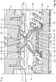
- Figure 12 illustrates an inventive electric contact zone 3 in which an electric contact portion 180 of a contact spring 10 and a counter-contact device 60 are connected in an electrically conductive manner.
- a deformation or movement direction, in particular an initial deformation and/or initial movement direction of the contact spring 10 or the contact portion 180 thereof is in many embodiments in some cases highly dependent on a friction coefficient between the contact portion 180 and the counter-contact device 60.
- an angled contact zone 3 is used in preference to a horizontal contact zone, a deformation of the contact spring 10 being able to be influenced by means of an angular position of an inclined abutment of the electric contact face 61 of the counter-contact device 60.
- an individual contact spring 10 and/or an individual counter-contact device 60 are constructed in such a manner and/or arranged in a respective device 4, 6 in such a manner that an electric contact face 61 or an electric contact portion 680 of the counter-contact device 60 is positioned in an inclined or oblique manner on the contact portion 180. That is to say, the contact face 61 or the contact portion 680 is arranged in an inclined or oblique manner with respect to an at least initial distortion direction V, compression direction V, deformation direction V and/or actuation direction V of the contact spring 10 and is thus not horizontal with respect thereto.
- the contact face 61 or the contact portion 680 is also arranged in an inclined or oblique manner at least with respect to a part-portion of a distortion path V, compression path V, deformation path V and/or actuation path V of the contact spring 10.
- the contact face 61 it is preferable for the contact face 61 to engage on the electric contact portion 180 of the contact spring 10 in such a manner that the contact portion 180 and consequently also the contact spring 10 are moved in the direction of the retention member 20.
- a kinematically inverted embodiment (not illustrated in the drawings) can naturally be used. That is to say, a location or a region of a deformation of a (third) resilient portion (170) and optionally other regions is determined by the inclination or the angle of the contact face 61 of the counter-contact device 60 and is no longer contingent as in the prior art.
- contact springs 30 arranged "back to back" in pairs are arranged on/in the retention member 20, the contact faces 61 which are arranged correspondingly are not parallel with each other but instead form an angle with respect to each other, which is preferably an obtuse angle.
Landscapes
- Coupling Device And Connection With Printed Circuit (AREA)
- Measuring Leads Or Probes (AREA)
Abstract
Description
- The invention relates to an electric contact zone and/or an electric device or apparatus.
- Electric contact springs and electric spring contact devices serve to electrically or electronically connect equipment, apparatuses, devices and/or components. In this instance, for example, two devices are mechanically connected, the electric contact springs of the one device being brought into an electrically conductive connection with electric counter-contact devices of the second device. Owing to the increasing miniaturisation in the electronic and electrical engineering sector, such electric devices are becoming increasingly compact, with an increasing number of functionalities. The contact springs and the counter-contact devices must thereby perform their function in contact spaces which are becoming smaller. In contrast, however, the requirements of the mechanical connection, for example with respect to tolerances, remain constant. That is to say, as the electric contact spaces become smaller, there are an increasing number of electric contact problems, which are exacerbated, for example, by the relaxation or ageing of the materials used and/or by temperature changes.
- The electrical contacting, for example, of printed circuit boards, boards, battery or accumulator packs thus presents an increasing number of problems. In this instance, the corresponding devices, such as, for example, electric tools, mobile telephones, cameras, computers, etc., and a large number of various associated battery or accumulator packs from different manufacturers, are subjected to comparatively high levels of mechanical tolerances which is to a large extent attributable to the compatibility of the associated device with the large number of different battery or accumulator packs. These tolerances must be overcome by the relevant electric contact springs or spring contact devices and the corresponding or complementary electric counter-contact devices, taking into account relaxation and optionally an increase of the tolerances owing to intensive loading. Owing to the miniaturisation and expansion of functionalities already mentioned above, an increasing number of contact springs must be located on the same surface or in the same spatial region in modern devices.
EP 0 902 994 B1 -
DE 20 2008 001 918 U1 discloses an integral electric contact spring for a bus conductor portion of a printed circuit board. The zig-zag shaped elongate contact spring is securely received between two portions of a housing of the bus conductor portion and protrudes at one end with an electric contact portion from the two-part housing. At an opposing end, the contact spring can be securely electrically connected to the printed circuit board by means of a soldering pin. The contact spring has two resilient portions which are connected by means of a resiliently rigid portion and which are each arranged by means of two bending portions in the contact spring, whereby a contact zone which is arranged horizontally with a counter-contact device allows the contact portion to expand in one direction or an opposing direction during electrical contacting. -
US 2006/0079136 A1 discloses an integral planar electric contact spring which is guided substantially completely in a housing. An electric contact portion of the contact spring that is guided by the housing in the direction of the spring protrudes from the housing and serves to provide horizontal electrical contacting with an electric counter-contact device. The contact spring has a plurality of resiliently flexible resilient portions which are connected by means of resiliently flexible bending portions and which are guided in a partially zig-zaglike manner inside the housing. The contact spring further has at the other side of the resilient and bending portions a projection which, when the contact spring is used in accordance with provisions, can be positioned on a resilient portion of the contact spring. An electrical property of the contact spring is thereby improved, which can now additionally also transport electric current and transmit electric voltage via the contact connection between the projection and the respective resilient portion. - An object is to provide an improved electric contact spring and/or spring contact device for small installation spaces for electrical contacting, in particular for electrical touch contacting, of electrical apparatuses or devices. An object of the invention is further to provide an electric contact zone for small installation spaces, in particular for electrical touch contacting of electrical apparatuses or devices. An object of the invention is further to provide an electrical device, for example, a battery or accumulator pack, and an electric apparatus or device, in particular a battery-operated or accumulator-operated apparatus or device and/or a substrate, in particular a printed circuit board.
- The electric contact spring or spring contact device which can be used for this, or the contact spring or spring contact device is intended in small installation spaces - taking into account relaxation and ageing and potentially an increase in mechanical tolerances owing to intensive loading - to overcome mechanical tolerances between two electrical connection partners, that is, the contact spring and an electric counter-contact device in a permanent and reliable manner and thus ensure operationally secure electrical contacting. The compensation of production and assembly tolerances in small installation spaces using the contact spring or spring contact device is further intended to ensure an at least minimal contact normal force over the entire service-life of the contact spring on the respective counter-contact device. Furthermore, it is intended to be able to assemble the spring contact device on a substrate in a simple manner, the quality of an electrical connection of the respective contact spring to the substrate being intended to be able to be readily verified.
- The object of the invention is achieved with an electric contact zone for small installation spaces, in particular for electrical contacting, preferably for electrical touch contacting, according to
claim 1; with an electric device, in particular a battery or accumulator pack, according to claim 9; and with an electric device or apparatus, in particular a battery-operated or accumulator-operated device or apparatus, or a substrate, in particular a printed circuit board, according toclaim 11. Advantageous developments, additional features and/or advantages of the invention will be appreciated from the dependent claims and the following description. - In order to use the electric contact spring in accordance with provisions, the contact spring for limiting a substantial mechanical tension of the contact spring is constructed in such a manner that the contact spring can be brought into abutment with itself and/or with a retention member, the contact spring being substantially exclusively resiliently deformable. The contact spring is further preferably constructed in such a manner that, even after a plastic deformation of the contact spring which exceeds this, sufficient contact normal force can still be applied. In this instance, a resilient portion and/or a bending portion of the contact spring may be able to be positioned on the contact spring itself, in particular an assembly portion of the contact spring. In this instance, the contact spring is preferably constructed in such a manner that for the functionality of the self-abutment no retention member or housing is necessary. Furthermore, a resilient portion and/or a bending portion of the contact spring may be able to be positioned on the retention member, the contact spring preferably being able to be mounted on/in the retention member. Furthermore, the contact spring may in particular be constructed in such a manner that, when the contact spring is actuated in accordance with provisions, the contact spring can first be brought into abutment with itself and afterwards with the retention member.
- The electric spring contact device has a retention member on/in which at least one electric contact spring is provided, the contact spring and/or retention member for limiting a mechanical tension of the contact spring being constructed in such a manner that, when the contact spring is used in accordance with provisions, a resilient portion and/or a bending portion of the contact spring can be positioned on the contact spring itself and/or any second resilient portion and/or any second bending portion can be positioned on the retention member. In this instance, in order to limit the mechanical tension of the contact spring, the contact spring can be constructed in such a manner that, when the contact spring is actuated in accordance with provisions, the relevant resilient portion and/or bending portion of the contact spring can be positioned on an assembly portion of the contact spring.
- The electric contact zone according to the invention has an electric contact spring and an electric counter-contact device for electrically contacting the contact spring, an electric contact face of the counter-contact device being able to be positioned or being positioned on the contact spring in an oblique manner with respect to a deformation direction of the contact spring. The contact zone may have an electric contact spring or a contact spring of an electric spring contact device.
- The electric device according to the invention has an electric counter-contact device for electrically contacting an electric contact spring of a second electric device. An electric contact face of the counter-contact device is arranged in an oblique manner with respect to a direction of relative movement which the device carries out when in a state connected to the second device in accordance with provisions; and/or an electric contact face of the counter-contact device is arranged in the device in such a manner that the contact face can be positioned on the contact spring in an oblique manner with respect to a deformation direction of the contact spring of the second device. In this instance, the device may have a plurality of counter-contact devices, the contact faces of the counter-contact devices being arranged at an angle, in particular an obtuse angle, with respect to each other.
- The electric device or apparatus according to the invention, or the electric substrate according to the invention, has an electric contact spring or an electric spring contact device. The apparatus according to the invention may further have an electric contact zone according to the invention. The apparatus according to the invention may further have a device according to the invention.
- In preferred embodiments, the electric contact spring and/or the retention member for limiting the mechanical tension of the contact spring is/are constructed in such a manner that, with increasing actuation of the contact spring in accordance with provisions, in particular with continued compression of the contact spring in accordance with provisions, a relevant resilient portion and/or bending portion can be moved away from the electric contact spring again, in particular the assembly portion.
- The contact spring may further be constructed in such a manner that, in the event of an initial compression of the contact spring, substantially an entire resilient region of the contact spring moves in a cushioning manner.
- When the relevant resilient portion and/or bending portion is positioned on the contact spring, in particular the assembly portion, a first stop zone is formed inside the contact spring. When the contact spring is compressed after the first stop zone has been formed, a respective free resilient region at the other side of the first stop zone of the contact spring can move in a cushioning manner. When the relevant resilient portion and/or bending portion is positioned on the retention member, a second stop zone may be formed between the electric contact spring and the retention member. When the contact spring is compressed after the second stop zone has been formed, a relevant free resilient region at the other side of the second stop zone of the contact spring may move in a cushioning manner. In this instance, the resilient portion and/or bending portion which is positioned on the contact spring itself may move away from the contact spring again, in particular the assembly portion.
- In embodiments, the electric contact spring may have at least two, in particular three, resilient portions which are preferably constructed as resilient arms and at least two, in particular three, bending portions which are preferably constructed with a u-shape or v-shape in cross-section. The resilient portions are arranged so as to be resilient with respect to each other in the contact spring. In this instance, the assembly portion of the contact spring may be adjoined by a first bending portion which is adjoined in succession by a first resilient portion, a second bending portion, a second resilient portion, a third bending portion and a third resilient portion, primarily in a zig-zag manner.
- The electric contact spring may be constructed in such a manner that the assembly portion is adjoined, preferably by means of a transition portion, by an electric contact portion for electrically contacting, for example the substrate, in particular the printed circuit board. Furthermore, the preferably third resilient portion is adjoined by the electric contact portion for electrically contacting the counter-contact device. The contact spring is in particular constructed in a materially integrated or integral manner. That is to say, for example, for a contact spring explained above, the electric contact portion for the substrate, the transition portion, the assembly portion, the first bending portion, the first resilient portion, the second bending portion, the second resilient portion, the third bending portion, the third resilient portion and/or the electric contact portion are constructed in a materially integrated or integral manner with each other.
- In preferred embodiments, the electric contact spring, apart from the assembly portion, a narrowed portion and/or a free longitudinal end portion of the electric contact spring, is, at a portion facing the free end of the contact spring in the longitudinal direction of the contact spring, constructed so as to be wider than a portion which faces a bound end of the contact spring. The contact spring may further be constructed in such a manner that, when the contact spring is in a state bent into shape, the electric contact portion for the substrate protrudes outwards from a resilient base of the contact spring and/or the retention member, the two electric contact portions in particular being arranged offset from one another with respect to an extent of the resilient base of the contact spring.
- In embodiments, the electric contact spring may be constructed as a blank or in a state bent into shape in such a manner that the electric contact portion for the substrate, the transition portion and/or one or more bending portions each have a constant width. Furthermore, the width of the first bending portion may be smaller than the width of the second and/or the third bending portion; and/or the width of the first bending portion may be substantially identical to that of the transition portion and/or that of the electric contact portion. Furthermore, the width of the second bending portion may be substantially identical to that of the third bending portion; and/or the first, the second and/or the third resilient portion may be constructed at one or both sides in the longitudinal direction of the contact spring in a stepped, conically tapering or narrowed manner.
- Furthermore, the first and/or the second resilient portion of the electric contact spring may be constructed so as to be narrower in width at an end facing in the direction of an assembly side of the contact spring than at a relevant opposing end; and/or the second and/or the third resilient portion may be constructed so as to be narrowed, preferably at both sides, the two respective longitudinal ends being able to have a width which is preferably identical. Furthermore, the second resilient portion, the third resilient portion and/or the electric contact portion for the counter-contact device may be constructed so as to taper conically in the direction of the free longitudinal end of the contact spring.
- In embodiments, the electric contact spring or the electric spring contact device may be constructed in such a manner that the contact spring can be secured or is secured to/in the retention member. In this instance, the assembly portion can be mounted, preferably by means of a catch device, in particular an integral catch device, preferably a catch hook, in the retention member or an assembly recess of the retention member for the assembly portion of the contact spring. The catch device preferably has at least one pair, preferably two or three pairs, of catch hooks, the two respective partners preferably being constructed so as to face each other at the transverse sides of the assembly portion. Furthermore, the retention member, in particular the assembly recess in the retention member and/or an outer abutment face on the retention member for the first and the second resilient region of the contact spring may be constructed in such a manner that the retention member substantially receives all the deformation forces of the electric contact spring.
- In embodiments, the electric contact spring or the electric spring contact device may be constructed in such a manner that a force which occurs when the contact spring is actuated in accordance with provisions is not orientated in the direction of the retention member. It is further preferable for the contact spring to be free from resiliently rigid regions in the resilient region thereof, that is to say, the electric contact spring preferably does not have any non-resilient regions. Furthermore, the electric contact portion for electrically contacting the substrate may be constructed as a connection face, a soldering connection with a soldering face or as a connection member or pin; and/or the electric contact portion for electrically contacting the counter-contact device may have a projection, a reinforcement rib, a crimped portion or a stamped portion, and/or may also be constructed in a slotted manner.
- In embodiments, the electric contact spring or spring contact device may be constructed in such a manner that one or more bending portions has/have a projection, a reinforcement rib, a crimped portion or a stamped portion; and/or one or more bending portions may have a constant material thickness in the blank stage or when the contact spring is in the state bent into shape. In this instance, it is preferable for the contact spring to be produced, in particular punched, from a metal sheet having a constant thickness.
- In embodiments, the electric contact spring and/or the retention member of the electric spring contact device is constructed in such a manner that the contact spring has comparatively high static friction in the first and/or second stop zone and/or the contact spring and the retention member may be constructed in such a manner that the contact spring has comparatively low sliding friction with respect to the retention member in the second stop zone. The retention member may be constructed as an open housing, the retention member preferably being constructed in such a manner that the contact springs can be mounted therein/thereon from the outer side. In this instance, the retention member may not have any soldering connection or may not have any soldering faces. The contact spring and/or the retention member or the electric spring contact device is preferably constructed as a component which can be mounted on the surface.
- Using the electric contact spring or the electric spring contact device, it is possible in small and extremely small installation spaces to provide a sufficiently great resilient path so that mechanical tolerances - taking into account relaxation or ageing, changes of temperature and optionally an increase in the mechanical tolerances owing to intensive loading - can be compensated for with at least a minimum contact normal force being maintained. Owing to the division of the contact spring into one or more resilient regions which function primarily independently of each other, it is possible, with a comparatively long resilient path, to limit mechanical tensions which occur on/in the contact spring by means of one or more stops and optionally during increasing deformation of the contact spring even to reduce them in a region.
- The spring contact device can be readily mounted on a substrate, the quality of an electrical connection of the respective contact spring to the substrate being able to be readily verified in embodiments, which can be carried out, for example, by means of automatic optical inspection (AOI) using a single camera, whereby an increase in the production quality is achieved. There is thereby produced an operationally reliable electrical contacting with a low subsequent likelihood of failure of the spring contact device. This is also promoted by the fact that, in the entire deformation region in accordance with provisions, substantially no forces act on the substrate via the contact spring. It can be used on all spring contact connections, with the installation spaces in particular being able to be small and the tolerances comparatively large.
- The invention is explained in greater detail below with reference to embodiments with reference to the appended drawings. In the detailed Figures:
-
Figure 1 is a front-end perspective view of an embodiment of an electric spring contact device with a plurality of electric contact springs; -
Figure 2 is a perspective front view from above of an embodiment of a retention member of the spring contact device; -
Figure 3 is a perspective side view of an embodiment of a contact spring in a state bent completely into shape; -
Figure 4 is a two-dimensional plan view of the contact spring fromFigure 3 after being punched out from a metal sheet and before being bent into shape; -
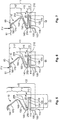
Figure 5 is a broken-away and two-dimensional lateral cross-section of an embodiment of the spring contact device before a deformation of a single contact spring in accordance with provisions; -
Figure 6 is an illustration which followsFigure 5 , an initial deformation of an entire resilient region of the contact spring being illustrated when a force is applied to the contact spring; -
Figure 7 is an illustration which followsFigure 6 , substantially a first resilient region of the contact spring coming to rest when force continues to be applied; -
Figure 8 is an illustration which followsFigure 7 , a second resilient region of the contact spring additionally coming to rest when force continues to be applied; -
Figure 9 is an illustration which followsFigure 8 , mechanical tensions being reduced in the first resilient region when force continues to be applied; -
Figure 10 is an illustration which followsFigure 9 , only a third free resilient region being deformed when force continues to be applied to the contact spring; -
Figure 11 is a quantitative overview table of the mechanical tensions which occur on/in the contact spring corresponding toFigures 5 to 10 ; and -
Figure 12 is a broken-away perspective cross-section of an electric apparatus in the region of a mutual electrical contacting of two devices of the apparatus. - The invention is explained in greater detail below with reference to an electric
spring contact device 1 orconnection device 1 for electrically contacting a printed circuit board to a housing or a housing cover having plug contacts, acarrier 20 orretention member 20 which acts as ahousing 20 orinner housing 20 retaining a plurality of electric contact springs 10 orspring contacts 10; seeFigure 1 . - In this instance, there are eight contact springs 10, with four contact springs 10 in each case being arranged opposite each other in two rows and being assembled in a mirror-symmetrical manner in the mirror-
symmetrical retention member 20. However, the invention is not limited to such an application, but instead can be used on all spring contact connections in which comparatively large mechanical tolerances are intended to be overcome. - In order to compensate for a mechanical tolerance, a single
electric contact spring 10 is constructed so as to be resiliently deformable over a comparatively long extent, that is to say, resilient. In the embodiment illustrated, there is primarily a three-stage deflection of thecontact spring 10 on theretention member 20, with two stop zones I, II for tworesilient regions contact spring 10 being formed when it is actuated or compressed. It is naturally possible, in a similar manner set out below, to provide only a two-stage or a four-stage deflection of the contact spring 10 (or a greater number of stages) on theretention member 20, that is to say, the electricspring contact device 1. The terms portion and region can be interpreted in the same manner below. -
Figure 2 illustrates theretention member 20 andFigure 3 an operationalelectric contact spring 10 in detail. The substantiallyparallelepipedal retention member 20 has at both longitudinal sides thereof a plurality of inwardly protruding assembly recesses 210 (see alsoFigures 1 and12 ) which are preferably all arranged in one plane and parallel with each other, the assembly recesses 210 of each longitudinal side preferably being arranged with the same spacing with respect to each other. The contact springs 10 can be mounted in the assembly recesses 210, which preferably have to this end an assembly portion 110 (see below) having acatch device 112 with in particular a plurality of catch hooks 112. As can be seen clearly inFigures 1 and12 , the contact springs 10 andretention member 20 are shaped in such a manner that the contact springs 10 extend out of their respective assembly recesses 210 and extend over an upper side of theretention member 20. That is to say, the contact springs 10 are resiliently movable above theretention member 20. - At the upper side (with reference to
Figures 1 and2 ) of theretention member 20, theretention member 20 has anoptional rib 260 which extends in the longitudinal direction of theretention member 20 along a centre line, therib 260 structuring theretention member 20 in two lateral regions for a plurality of contact springs 10, respectively. Furthermore, theretention member 20 has perpendicularly relative to the rib 260 a plurality of guidingribs 240 which guide at one or both sides an upper region of thecontact spring 10. Preferably, theretention member 20 has for n or n/2 contact springs 10 n-1guiding ribs 240. At the top in the transverse and longitudinal direction of theretention member 20 and adjacent to the guidingribs 240, the retention member for the contact springs 10 has outer abutment faces 250 which are each constructed in a substantially corresponding or complementary manner to a secondresilient portion 150 and/or a third bending portion 160 (see below) of acontact spring 10. - At a lower side, the
retention member 20 may havefeet 220 by means of which theretention member 20 can be positioned on asubstrate 40, for example, a printedcircuit board 20, aboard 20, acircuit board 20 or a punchedlattice 20. In this instance, thefeet 220 may serve to locate theretention member 20 on thesubstrate 40. However, it is also possible to use other devices for this, for example, one or more projections, which either protrude downwards from the retention member and/or protrude from thesubstrate 40 into theretention member 20, positive-locking recesses preferably being used for the respective projection. - The electric
spring contact device 1 is constructed in such a manner that theretention member 20 in a state assembled on thesubstrate 40 primarily or substantially receives all the forces and directs them via its mechanical connection to thesubstrate 40 into thesubstrate 40. Such forces are in particular assembly, pre-tensioning and application forces. This is carried out by means of a design of theretention member 20 and an assembly position of thecontact spring 10 on/in theretention member 20 and on/at thesubstrate 40. Furthermore, thecontact spring 10 can be assembled from the outer side on/in theretention member 20 and may operate openly and externally on the retention member, whereby an extensive closed or surrounding housing can be dispensed with. - Reference is made below in most cases to only one detail, that is to say, a single
electric contact spring 10 and a singlerelevant assembly region 22 of thecontact spring 10 on/in theretention member 20. However, what has been said can be applied similarly to any number ofassembly regions 22 and contact springs 10 and in any arrangement of theassembly regions 22 and contact springs 10. Asingle assembly region 22 is delimited by therib 260, one or two guidingribs 240 and theabutment face 250, theassembly region 22 being open opposite therib 260, that is to say, in this instance theassembly region 22 is freely accessible for thecontact spring 10. In this instance, theabutment face 250 is arranged in an inclined manner with respect to a base, that is to say, for example, the lower side, of theretention member 20 and merges via a radius into therib 260. - The
electric contact spring 10 has in the present embodiment, starting from anelectric contact portion 100, atransition portion 105, theassembly portion 110, afirst bending portion 120, a firstresilient portion 130, asecond bending portion 140, the secondresilient portion 150, thethird bending portion 160, a thirdresilient portion 170, which can also be referred to as afourth bending portion 170 and anelectric contact portion 180. Theassembly portion 110 and theresilient portions spring base 18 via the bendingportions spring base 18 of thecontact spring 10, the bending portions preferably being arranged within a width (seeFigure 5 ) of thespring base 18. In this instance, theresilient portions leaf springs resilient arms contact spring 10 is thereby small and/or narrow in the operational direction thereof. - The
contact portion 100 serves to electrically contact thesubstrate 40, thecontact portion 100 being constructed in particular as asoldering connection 100 having a soldering face, contact face or connection face. That is to say, the electricspring contact device 1 is preferably constructed as an SMD (surface mounted device). Furthermore, thecontact portion 100 may also be constructed as a connection leg/pin, such as, for example, a soldering pin (not illustrated in the drawings). In this instance, it is preferable for theretention member 10 to have no soldering connections and theresilient contact device 1 to be able to be mechanically secured to thesubstrate 40 only by means of its contact springs 10 and to be able to be brought into electrically conductive contact with a corresponding electrical strip conductor or line. - The
contact portion 180 serves to electrically contact an electric counter-contact device 60 (seeFigures 5 to 10 and12 ). The counter-contact device 60 (seeFigure 12 ) is a component of anelectric device 6, in this instance a component of anelectric apparatus 2,component 2,device 2,appliance 2, etc. Theapparatus 2 further comprises anelectric device 4, which is, for example, battery-operated or accumulator-operated. Thecontact portion 180 which is preferably in the shape of a half-moon when viewed from the side may have a crimpedportion 182, aprojection 182, areinforcement rib 182 or a stampedportion 182. Furthermore, thecontact portion 180 may be slotted. - The
electric contact spring 10 extends primarily in its longitudinal direction L, which, when thecontact spring 10 is in the state bent into shape, follows the zig-zag path thereof (seeFigure 3 ). Thecontact spring 10 further has a variable width B and a preferably constant thickness D.Figure 4 illustrates thecontact spring 10 in a blank state before it is bent into shape. In this instance, it is preferable for theelectric contact portion 180 and the thirdresilient portion 170 to become wider in the direction of an assembly side and for the secondresilient portion 150 to be constructed in a narrowed manner. It is further preferable for the firstresilient portion 130 to be constructed in a stepped manner and to have a smaller width B at the assembly side. The bendingportions portions portion 120. - An entire free resilient region 11 (see
Figures 4 to 10 ) of the illustrated embodiment of thecontact spring 10 is subdivided into threeresilient regions resilient region 13 is formed by thefirst bending portion 120, the firstresilient portion 130 and an adjacent portion of thesecond bending portion 140. A secondresilient region 15 is formed by the remaining portion of thesecond bending portion 140, the secondresilient portion 150 and an adjacent portion of thethird bending portion 160. A thirdresilient region 17 is formed by the remaining portion of thethird bending portion 160, the thirdresilient portion 170 and theelectric contact portion 180. - A resilient space for the
contact spring 10, that is to say, a spatial region in which the resilient region of thecontact spring 10 is provided, is produced from a width of thespring base 18 together with the height of theresilient region 11 and the width B of thecontact spring 10. A deformation of thecontact spring 10 is subdivided into a plurality ofresilient regions resilient portions Figure 11 ) on/in thecontact spring 10 in a specific region of thecontact spring 10. There is thereby produced a current, that is to say, still available, resilient path of thecontact spring 10, from a height of theresilient regions resilient portions contact spring 10 which can still be deflected, which is illustrated inFigures 5 to 10 . - Below, a force F acts on the
electric contact spring 10 in the distortion direction V, the compression direction V, deformation direction V or actuation direction V thereof, the force F increasing from zero "0" (seeFigure 11 ) inFigure 5 substantially to the maximum inFigure 10 .Figure 11 clarifies in this regard in a qualitative manner the mechanical tensions σ of thecontact spring 10 which occur in therespective portions respective portion - The
electric contact spring 10 is constructed in the present embodiment in such a manner that, in the event of an initial loading of thecontact spring 10, the entireresilient region 11 of thecontact spring 10 is deflected in a substantially uniform manner, the mechanical tensions σ in therespective bending portions resilient portions Figures 6 and11 ). - The
electric contact spring 10 is further constructed in such a manner that, when the force F on thecontact spring 10 increases, a first or internal stop zone I is arranged or formed inside thecontact spring 10, thesecond bending portion 140 and/or the firstresilient portion 130 moving into abutment against astop 114 on theassembly portion 110 of thecontact spring 10. A resilient movement primarily of the firstresilient region 13 thereby stops, whereby the mechanical tensions σ no longer increase if the force F continues to increase. Until the first stop zone I is established, there is a substantial increase of the mechanical tensions σ primarily in therespective bending portions Figures 7 and11 ). - If the force F continues to increase, mainly only the second
resilient region 15 and thirdresilient region 17 of theelectric contact spring 10 become deflected, whereby the mechanical tensions σ in theportions contact spring 10 and theretention member 20 are constructed in such a manner that thethird bending portion 160 and/or the secondresilient portion 150 move into abutment against a stop 255 (see alsoFigures 1 and2 ) on theabutment face 250 of theretention member 20. The secondresilient region 15 of thecontact spring 10 thereby primarily also comes to rest, whereby the mechanical tensions σ also no longer increase in this instance if the force F continues to increase. Until the second stop zone II is established, there is a significant increase of the mechanical tensions σ primarily in therespective bending portions 140, 160 (seeFigure 8 and11 ). - If the force F continues to increase, primarily only the third
resilient region 17 of theelectric contact spring 10 becomes deflected, the mechanical tensions σ in theportions third bending portion 160 and the secondresilient portion 150 and theabutment face 250 of theretention member 20 with respect to theinclined abutment face 250. If, for example, anelectric contact face 61 of thecounter-contact device 60 is arranged in such an inclined manner with respect to the deformation direction V of thecontact spring 10 or if the force F engages in such an inclined manner on theelectric contact portion 180 that the stop zone II moves theinclined abutment face 250 upwards, thesecond bending portion 140 or the firstresilient portion 130 can move away from theassembly portion 110 again (Figure 9 ), whereby the mechanical tensions σ in thefirst bending portion 120 and in thesecond bending portion 140 may decrease (seeFigures 9 to 11 ). - In this instance, there is a significant increase of the mechanical tensions σ in the bending
portion 160 which remain at a high level. Theelectric contact spring 10 is constructed so as to comply with loads, theelectric contact portion 180 preferably being constructed in a rigid manner at one side by means of the crimpedportion 182. High levels of mechanical tensions σ further occur in the transition from thecontact portion 180 to the thirdresilient portion 170 and from there to the transition of thethird bending portion 160 to the secondresilient portion 150. The transition from thecontact portion 180 to thethird bending portion 170 is preferably strengthened by means of the crimpedportion 182 which extends into the thirdresilient portion 170. The thirdresilient portion 170 is further constructed so as to increase in terms of its width B in order to be able to compensate for the mechanical tensions σ which occur, thethird bending portion 160 also having a comparatively large width B. - The stop zones I, II are arranged in this instance in such a manner that a primary movement stop takes place, an additional substantial deformability of the
electric contact spring 10 being brought about "elsewhere". In this instance, a bearing or counter-bearing of thecontact spring 10 in theretention member 20 is not intended to be a stop. It is notable in the construction of theelectric contact spring 10 that, in thecontact portion 100 for electrically contacting thesubstrate 40, the mechanical tensions σ in all forces F which occur when thecontact spring 10 is used in accordance with provisions are substantially zero, whereby solder contact arrangements which are provided there have a high level of durability. - Other embodiments of electric
spring contact devices 1 can naturally be used. It is, for example, possible to adjust only the first stop zone I or only the second stop zone II for thecontact spring 10. On the other hand, theelectric contact spring 10 and theretention member 20 may be constructed in such a manner that firstly a second stop zone II and afterwards a first stop zone I is formed. Generally, theelectric contact spring 10 and theretention member 20 may be constructed in such a manner that a single stop zone I/II or any combination of stop zones I, II can be provided; that is to say, more than two (1,1; I,II; II,I; II,II) stop zones I, II may also be used. -
Figure 12 illustrates an inventiveelectric contact zone 3 in which anelectric contact portion 180 of acontact spring 10 and acounter-contact device 60 are connected in an electrically conductive manner. A deformation or movement direction, in particular an initial deformation and/or initial movement direction of thecontact spring 10 or thecontact portion 180 thereof is in many embodiments in some cases highly dependent on a friction coefficient between thecontact portion 180 and thecounter-contact device 60. According to the invention, anangled contact zone 3 is used in preference to a horizontal contact zone, a deformation of thecontact spring 10 being able to be influenced by means of an angular position of an inclined abutment of theelectric contact face 61 of thecounter-contact device 60. - In this instance, an
individual contact spring 10 and/or an individualcounter-contact device 60 are constructed in such a manner and/or arranged in arespective device electric contact face 61 or anelectric contact portion 680 of thecounter-contact device 60 is positioned in an inclined or oblique manner on thecontact portion 180. That is to say, thecontact face 61 or thecontact portion 680 is arranged in an inclined or oblique manner with respect to an at least initial distortion direction V, compression direction V, deformation direction V and/or actuation direction V of thecontact spring 10 and is thus not horizontal with respect thereto. That is to say that thecontact face 61 or thecontact portion 680 is also arranged in an inclined or oblique manner at least with respect to a part-portion of a distortion path V, compression path V, deformation path V and/or actuation path V of thecontact spring 10. - In this instance, it is preferable for the
contact face 61 to engage on theelectric contact portion 180 of thecontact spring 10 in such a manner that thecontact portion 180 and consequently also thecontact spring 10 are moved in the direction of theretention member 20. A kinematically inverted embodiment (not illustrated in the drawings) can naturally be used. That is to say, a location or a region of a deformation of a (third) resilient portion (170) and optionally other regions is determined by the inclination or the angle of thecontact face 61 of thecounter-contact device 60 and is no longer contingent as in the prior art. Since, in this instance contact springs 30 arranged "back to back" in pairs are arranged on/in theretention member 20, the contact faces 61 which are arranged correspondingly are not parallel with each other but instead form an angle with respect to each other, which is preferably an obtuse angle. -
- 1. Electric contact spring for small installation spaces, in particular for electrical touch contacting, for use of the electric contact spring (10) in accordance with provisions, the electric contact spring (10)
for limiting a mechanical tension (σ) of the electric contact spring (10) being constructed in such a manner that
the electric contact spring (10) can be brought into abutment with itself (I) and a retention member (20) (II), the electric contact spring (10) being substantially exclusively resiliently deformable. - 2. Electric contact spring according to the preceding embodiment, a resilient portion (130) and/or a bending portion (140) of the electric contact spring (10) being able to be positioned on the electric contact spring (10), in particular an assembly portion (110) of the electric contact spring (10) (I),
a resilient portion (150) and/or a bending portion (160) of the electric contact spring (10) being able to be positioned on the retention member (20) (II) and the electric contact spring (10) preferably being able to be mounted on/in the retention member (20), and/or
the electric contact spring (10) being constructed particularly in such a manner that, when the electric contact spring (10) is actuated in accordance with provisions, the electric contact spring (10) can be brought into abutment firstly with itself (I) and afterwards with the retention member (20) (II). - 3. Electric spring contact device for small installation spaces, in particular for electrically contacting electric devices or apparatuses, having a retention member (20), on/in which at least one electric contact spring (10) is provided,
the electric contact spring (10) and the retention member (20) for limiting a mechanical tension (σ) of the electric contact spring (10) being constructed in such a manner that, when the electric contact spring (10) is used in accordance with provisions, a resilient portion (150) and/or a bending portion (160) of the electric contact spring (10) can be positioned on the retention member (20). - 4. Electric spring contact device according to the preceding embodiment, the electric contact spring (10) for limiting the mechanical tension (σ) of the electric contact spring (10) being constructed in such a manner that,
when the electric contact spring (10) is actuated in accordance with provisions, a resilient portion (130) and/or a bending portion (140) of the electric contact spring (10) can be positioned (I) on the electric contact spring (10), in particular an assembly portion (110) of the electric contact spring (10). - 5. Electric contact spring or electric spring contact device according to any one of the preceding embodiments, the electric contact spring (10) and/or the retention member (20) for delimiting the mechanical tension (σ) of the electric contact spring (10) being constructed in such a manner that,
if the electric contact spring (10) is increasingly actuated in accordance with provisions, in particular compressed continuously in accordance with provisions, the resilient portion (130) and/or the bending portion (140) can again be moved away from the electric contact spring (10), in particular the assembly portion (110). - 6. Electric contact spring or electric spring contact device according to any one of the preceding embodiments, the electric contact spring (10) being constructed in such a manner that:
- substantially an entire resilient region (11; 120, 130, 140, 150, 160, 170, 180) of the electric contact spring (10) moves resiliently in the case of initial actuation of the electric contact spring (10);
- a first stop zone (I) within the electric contact spring (10) is formed when the resilient portion (130) and/or the bending portion (140) is/are positioned against the electric contact spring (10), in particular the assembly portion (110);
- substantially a free resilient region (15, 17; (140), 150, 160, 170, 180) moves resiliently at the other side of the first stop zone (I) of the electric contact spring (10) when the electric contact spring (10) is actuated after the first stop zone (I) is formed;
- a second stop zone (II) is formed between the electric contact spring (10) and the retention member (20) when the resilient portion (150) and/or bending portion (160) is/are positioned against the retention member (20); and/or
- substantially a free resilient region (17; 160, 170, 180) moves resiliently at the other side of the second stop zone (II) of the electric contact spring (10) when the electric contact spring (10) is actuated after the second stop zone (II) is formed.
- 7. Electric contact spring or electric spring contact device according to any one of the preceding embodiments,
- the electric contact spring (10) being constructed in a materially integrated or integral manner;
- the electric contact spring (10) being constructed in such a manner that, when the electric contact spring (10) is in a state bent into shape, the electric contact portion (100) protrudes outwardly from a spring base (18) of the electric contact spring (10) and/or the retention member (20) and in particular the two electric contact portions (100, 180) are arranged offset relative to each other with respect to the spring base (18) in the longitudinal direction thereof;
- the retention member (20) being in the form of an open housing (20), the retention member (20) being constructed in such a manner that the electric contact springs (10) can be mounted from the outer side therein/thereon; and/or
- the retention member (20), in particular an assembly recess (210) in the retention member (20) and/or an outer abutment face (250) on the retention member (20) for a first resilient region (13) or a second resilient region (15) of the electric contact spring (10), being constructed in such a manner that the retention member (20) substantially takes up all the deformation forces of the electric contact spring (10).
- 8. Electric or electronic contact zone for small installation spaces, in particular for electrical contacting, preferably for electrical touch contacting, having
an electric contact spring (10) and an electric counter-contact device (60) for electrically contacting the electric contact spring (10),
an electric contact face (61) of the electric counter-contact device (60) being able to be positioned and/or being positioned on the electric contact spring (10) obliquely with respect to a deformation direction (V) of the electric contact spring (10). - 9. Electric or electronic contact zone according to the preceding embodiment, the electric contact spring (10) of the contact zone (3) being constructed according to any one of
embodiments 1 to 7 or
the electric contact spring (10) of the contact zone (3) being the one of an electric spring contact device (1) which is constructed according to any one ofembodiments 3 to 7. - 10. Electric or electronic device, the device (6) having an electric counter-contact device (60) for electrically contacting an electric contact spring (10) of a second electric or electronic device (4),
an electric contact face (61) of the electric counter-contact device (60) being arranged obliquely with respect to a direction of relative movement which the device (6) carries out in the event of connection to the second electric device (4) in accordance with provisions; and/or
an electric contact face (61) of the electric counter-contact device (60) being arranged in the device (6) in such a manner that the electric contact face (61) can be positioned obliquely on the electric contact spring (10) with respect to a deformation direction (V) of the electric contact spring (10) of the second device (4). - 11. Electric or electronic device according to the preceding embodiment, the device (6) having a plurality of electric counter-contact devices (60), the electric contact faces (61) of the counter-contact devices (60) being arranged at an angle, particularly an obtuse angle, with respect to each other.
- 12. Electric or electronic device or apparatus, in particular battery-operated or accumulator-operated device (4) or apparatus (2), or substrate, in particular printed circuit board (40), the device (4), apparatus (2) or substrate (40) having an electric contact spring (10) or an electric spring contact device (1) which is constructed according to any one of
embodiments 1 to 7,
the apparatus (2) having an electric or electronic contact zone (3) which is constructed according to either of embodiments 8 or 9 and/or
the apparatus (2) having a device (6) which is constructed according toembodiment 10 orembodiment 11.
Claims (11)
- Electric contact zone (3) for small installation spaces, in particular for electrical contacting, preferably for electrical touch contacting, having
an electric contact spring (10) and an electric counter-contact device (60) for electrically contacting the contact spring (10), wherein
an electric contact face (61) of the counter-contact device (60) is able to be positioned and/or is positioned on the contact spring (10) obliquely with respect to a deformation direction (V) of the contact spring (10). - Electric contact zone (3) according to the preceding claim, comprising an contact spring (10) for small installation spaces, in particular for electrical touch contacting, for use of the contact spring (10) in accordance with provisions, wherein
the contact spring (10) for delimiting a mechanical tension (σ) of the contact spring (10) is constructed in such a manner that the contact spring (10) can be brought into abutment with itself (I) and a retention member (20) (II), wherein the contact spring (10) is substantially exclusively resiliently deformable. - Electric contact zone (3) according to any one of the preceding claims, wherein a resilient portion (130) and/or a bending portion (140) of the contact spring (10) is able to be positioned on the contact spring (10), in particular an assembly portion (110) of the contact spring (10) (I), wherein
a resilient portion (150) and/or a bending portion (160) of the contact spring (10) is able to be positioned on the retention member (20) (II) and the contact spring (10) preferably is able to be mounted on/in the retention member (20), and/or
the contact spring (10) is constructed particularly in such a manner that, when the contact spring (10) is actuated in accordance with provisions, the contact spring (10) can be brought into abutment firstly with itself (I) and afterwards with the retention member (20) (II). - Electric contact zone (3) according to any one of the preceding claims, comprising an electric spring contact device for small installation spaces, in particular for electrically contacting electric devices or apparatuses, having a retention member (20), on/in which at least one contact spring (10) is provided, wherein
the contact spring (10) and the retention member (20) for delimiting a mechanical tension (σ) of the contact spring (10) is constructed in such a manner that,
when the contact spring (10) is used in accordance with provisions, a resilient portion (150) and/or a bending portion (160) of the contact spring (10) can be positioned on the retention member (20) (II). - Electric contact zone (3) according to any one of the preceding claims, wherein the contact spring (10) for delimiting the mechanical tension (σ) of the contact spring (10) is constructed in such a manner that,
when the contact spring (10) is actuated in accordance with provisions, a resilient portion (130) and/or a bending portion (140) of the contact spring (10) can be positioned on the contact spring (10) (I), in particular an assembly portion (110) of the contact spring (10). - Electric contact zone (3) according to any one of the preceding claims, wherein the contact spring (10) and/or the retention member (20) for delimiting the mechanical tension (σ) of the contact spring (10) is constructed in such a manner that,
if the contact spring (10) is increasingly actuated in accordance with provisions, in particular compressed continuously in accordance with provisions, the resilient portion (130) and/or bending portion (140) can again be moved away from the contact spring (10), in particular the assembly portion (110). - Electric contact zone (3) according to any one of the preceding claims, wherein the contact spring (10) is constructed in such a manner that:• substantially an entire resilient region (11; 120, 130, 140, 150, 160, 170, 180) of the contact spring (10) moves resiliently in the case of initial actuation of the contact spring (10);• a first stop zone (I) within the contact spring (10) is formed when the resilient portion (130) and/or bending portion (140) is/are positioned against the contact spring (10), in particular the assembly portion (110);• substantially a free resilient region (15, 17; (140,) 150, 160, 170, 180) of the contact spring (10) moves resiliently over the first stop zone (I) of the contact spring (10) when the contact spring (10) is actuated after the first stop zone (I) is formed;• a second stop zone (II) is formed between the contact spring (10) and the retention member (20) when the resilient portion (150) and/or bending portion (160) is/are positioned against the retention member (20); and/or• substantially a free resilient region (17; 160, 170, 180) of the contact spring (10) moves resiliently over the second stop zone (II) of the contact spring (10) when the contact spring (10) is actuated after the second stop zone (II) is formed.
- Electric contact zone (3) according to any one of the preceding claims, wherein:• the contact spring (10) is constructed in a materially integrated or integral manner;• the contact spring (10) is constructed in such a manner that, when the contact spring (10) is in a state bent into shape, an electric contact portion (100) protrudes outwardly from a spring base (18) of the contact spring (10) and/or the retention member (20), and in particular the two electric contact portions (100, 180) are arranged offset relative to each other with respect to the spring base (18) in the longitudinal direction thereof;• the retention member (20) is in the form of an open housing (20), the retention member (20) is constructed in such a manner that the contact springs (10) can be mounted from the outer side therein/thereon; and/or• the retention member (20), in particular an assembly recess (210) in the retention member (20) and/or an outer abutment face (250) on the retention member (20) for a first resilient region (13) or a second resilient region (15) of the contact spring (10), is constructed in such a manner that the retention member (20) substantially takes up all the deformation forces of the contact spring (10).
- Electric device (6), wherein the electric device (6) has an electric counter-contact device (60) for electrically contacting an electric contact spring (10) of a second electric device (4), wherein
an electric contact face (61) of the counter-contact device (60) is arranged obliquely with respect to a direction of relative movement which the electric device (6) carries out in the event of connection to the second electric device (4) in accordance with provisions; and/or
an electric contact face (61) of the counter-contact device (60) is arranged in the electric device (6) in such a manner that the electric contact face (61) can be positioned obliquely on the contact spring (10) with respect to a deformation direction (V) of the contact spring (10) of the second electric device (4). - Electric device (6) according to the preceding claim, wherein the electric device (6) having a plurality of counter-contact devices (60), and the electric contact faces (61) of the counter-contact devices (60) is arranged at an angle, particularly an obtuse angle, with respect to each other.
- Electric device (4) or apparatus (2), in particular battery-operated or accumulator-operated device (4) or apparatus (2), or substrate (40), in particular printed circuit board (40), wherein
the device (4), the apparatus (2) or the substrate (40) having an electric contact zone (3) and/or an electric device (6) constructed according to one of the preceding claims.
Applications Claiming Priority (3)
| Application Number | Priority Date | Filing Date | Title |
|---|---|---|---|
| DE102011080645A DE102011080645A1 (en) | 2011-08-09 | 2011-08-09 | ELECTRIC CONTACT SPRING, ELECTRIC SPRING CONTACT DEVICE AND ELECTRIC CONTACT ZONE |
| EP12751024.6A EP2742562B1 (en) | 2011-08-09 | 2012-08-06 | Electric contact spring, electric spring contact device as well as electric contact zone |
| PCT/EP2012/065345 WO2013020948A1 (en) | 2011-08-09 | 2012-08-06 | Electric contact spring, electric spring contact device as well as electric contact zone |
Related Parent Applications (2)
| Application Number | Title | Priority Date | Filing Date |
|---|---|---|---|
| EP12751024.6A Division-Into EP2742562B1 (en) | 2011-08-09 | 2012-08-06 | Electric contact spring, electric spring contact device as well as electric contact zone |
| EP12751024.6A Division EP2742562B1 (en) | 2011-08-09 | 2012-08-06 | Electric contact spring, electric spring contact device as well as electric contact zone |
Publications (2)
| Publication Number | Publication Date |
|---|---|
| EP3361577A1 true EP3361577A1 (en) | 2018-08-15 |
| EP3361577B1 EP3361577B1 (en) | 2021-09-22 |
Family
ID=46750296
Family Applications (2)
| Application Number | Title | Priority Date | Filing Date |
|---|---|---|---|
| EP18155448.6A Active EP3361577B1 (en) | 2011-08-09 | 2012-08-06 | Electric contact zone |
| EP12751024.6A Active EP2742562B1 (en) | 2011-08-09 | 2012-08-06 | Electric contact spring, electric spring contact device as well as electric contact zone |
Family Applications After (1)
| Application Number | Title | Priority Date | Filing Date |
|---|---|---|---|
| EP12751024.6A Active EP2742562B1 (en) | 2011-08-09 | 2012-08-06 | Electric contact spring, electric spring contact device as well as electric contact zone |
Country Status (6)
| Country | Link |
|---|---|
| US (1) | US9184529B2 (en) |
| EP (2) | EP3361577B1 (en) |
| JP (1) | JP2014525644A (en) |
| CN (1) | CN103858288B (en) |
| DE (1) | DE102011080645A1 (en) |
| WO (1) | WO2013020948A1 (en) |
Families Citing this family (7)
| Publication number | Priority date | Publication date | Assignee | Title |
|---|---|---|---|---|
| DE202015003001U1 (en) | 2015-04-23 | 2015-06-25 | Rosenberger Hochfrequenztechnik Gmbh & Co. Kg | Plug system with low-wear contact |
| CN107996033A (en) * | 2015-06-26 | 2018-05-04 | 博世汽车多媒体葡萄牙公司 | Springs for fixing and grounding contacts of printed circuit boards |
| JP6684419B2 (en) * | 2016-03-02 | 2020-04-22 | 北川工業株式会社 | contact |
| JP6744209B2 (en) * | 2016-12-27 | 2020-08-19 | 株式会社エンプラス | Sockets for electrical contacts and electrical components |
| JP2020064724A (en) * | 2018-10-15 | 2020-04-23 | 第一精工株式会社 | Terminal and connector |
| US11808116B2 (en) | 2020-06-23 | 2023-11-07 | Halliburton Energy Services, Inc. | Connector for perforating gun system |
| DE102021116787B3 (en) * | 2021-06-30 | 2022-11-24 | Lisa Dräxlmaier GmbH | VOLTAGE TAP FOR MEASURING A VOLTAGE |
Citations (11)
| Publication number | Priority date | Publication date | Assignee | Title |
|---|---|---|---|---|
| US5259769A (en) * | 1992-09-29 | 1993-11-09 | Molex Incorporated | Electrical connector with preloaded spring-like terminal with improved wiping action |
| DE19501651A1 (en) * | 1995-01-18 | 1996-07-25 | Siemens Ag | Electrical connector for contacting a device provided with flat contacts, in particular a mobile telephone handset |
| EP1150386A2 (en) * | 2000-04-28 | 2001-10-31 | Hirose Electric Co., Ltd. | Stationary device for a mobile device and an electrical connection for the stationary device |
| EP0902994B1 (en) | 1996-05-31 | 2001-11-28 | The Whitaker Corporation | Rechargeable battery connector |
| US6343018B1 (en) * | 1999-01-25 | 2002-01-29 | Yamaichi Electronics Co., Ltd. | Card connector mounting structure |
| US20040115998A1 (en) * | 2002-12-13 | 2004-06-17 | Hosiden Corporation | Battery connector |
| US20060079136A1 (en) | 2004-10-07 | 2006-04-13 | Shih-Fu Wei | Elastic terminal |
| US20060252291A1 (en) * | 2005-03-16 | 2006-11-09 | Noriyuki Sano | Detachable connector and front-panel device including same |
| US20070178719A1 (en) * | 2003-06-11 | 2007-08-02 | Cinch Connectors, Inc. | Electrical connector |
| DE202008001918U1 (en) | 2008-02-11 | 2009-06-25 | Weidmüller Interface GmbH & Co. KG | In a housing arranged compression spring contact |
| US20100136855A1 (en) * | 2008-11-28 | 2010-06-03 | Samsung Electronics Co., Ltd. | Contact terminal for electronic device |
Family Cites Families (13)
| Publication number | Priority date | Publication date | Assignee | Title |
|---|---|---|---|---|
| US5879169A (en) * | 1996-03-18 | 1999-03-09 | Hon Hai Precision Ind. Co., Ltd. | Card connector |
| JPH11250966A (en) * | 1997-12-22 | 1999-09-17 | Whitaker Corp:The | connector |
| JP4365949B2 (en) * | 1999-08-25 | 2009-11-18 | モレックス インコーポレイテド | Board connector |
| JP3634998B2 (en) * | 2000-02-09 | 2005-03-30 | ヒロセ電機株式会社 | Electrical connector |
| SG99960A1 (en) * | 2001-11-23 | 2003-11-27 | Fci Asia Technology Pte Ltd | Electrical connector |
| JP3595939B2 (en) * | 2002-03-29 | 2004-12-02 | 日本航空電子工業株式会社 | connector |
| JP2004265598A (en) * | 2002-12-16 | 2004-09-24 | Iriso Denshi Kogyo Kk | connector |
| TWM300874U (en) * | 2006-06-02 | 2006-11-11 | Advanced Connectek Inc | Battery connector |
| JP4684191B2 (en) * | 2006-09-08 | 2011-05-18 | イリソ電子工業株式会社 | connector |
| US7381086B1 (en) * | 2007-02-01 | 2008-06-03 | Motorola, Inc. | High reliability battery contact assembly and method of forming same |
| CN201054407Y (en) * | 2007-05-22 | 2008-04-30 | 富士康(昆山)电脑接插件有限公司 | Electric connector |
| DE202008001018U1 (en) | 2008-01-29 | 2009-06-25 | Pepperl + Fuchs Gmbh | Sensor for the detection of objects by light diffraction |
| TWM344641U (en) * | 2008-04-01 | 2008-11-11 | Htc Corp | Battery connector |
-
2011
- 2011-08-09 DE DE102011080645A patent/DE102011080645A1/en active Pending
-
2012
- 2012-08-06 WO PCT/EP2012/065345 patent/WO2013020948A1/en not_active Ceased
- 2012-08-06 CN CN201280049645.3A patent/CN103858288B/en active Active
- 2012-08-06 EP EP18155448.6A patent/EP3361577B1/en active Active
- 2012-08-06 EP EP12751024.6A patent/EP2742562B1/en active Active
- 2012-08-06 JP JP2014524355A patent/JP2014525644A/en active Pending
-
2014
- 2014-02-10 US US14/176,430 patent/US9184529B2/en active Active
Patent Citations (11)
| Publication number | Priority date | Publication date | Assignee | Title |
|---|---|---|---|---|
| US5259769A (en) * | 1992-09-29 | 1993-11-09 | Molex Incorporated | Electrical connector with preloaded spring-like terminal with improved wiping action |
| DE19501651A1 (en) * | 1995-01-18 | 1996-07-25 | Siemens Ag | Electrical connector for contacting a device provided with flat contacts, in particular a mobile telephone handset |
| EP0902994B1 (en) | 1996-05-31 | 2001-11-28 | The Whitaker Corporation | Rechargeable battery connector |
| US6343018B1 (en) * | 1999-01-25 | 2002-01-29 | Yamaichi Electronics Co., Ltd. | Card connector mounting structure |
| EP1150386A2 (en) * | 2000-04-28 | 2001-10-31 | Hirose Electric Co., Ltd. | Stationary device for a mobile device and an electrical connection for the stationary device |
| US20040115998A1 (en) * | 2002-12-13 | 2004-06-17 | Hosiden Corporation | Battery connector |
| US20070178719A1 (en) * | 2003-06-11 | 2007-08-02 | Cinch Connectors, Inc. | Electrical connector |
| US20060079136A1 (en) | 2004-10-07 | 2006-04-13 | Shih-Fu Wei | Elastic terminal |
| US20060252291A1 (en) * | 2005-03-16 | 2006-11-09 | Noriyuki Sano | Detachable connector and front-panel device including same |
| DE202008001918U1 (en) | 2008-02-11 | 2009-06-25 | Weidmüller Interface GmbH & Co. KG | In a housing arranged compression spring contact |
| US20100136855A1 (en) * | 2008-11-28 | 2010-06-03 | Samsung Electronics Co., Ltd. | Contact terminal for electronic device |
Also Published As
| Publication number | Publication date |
|---|---|
| DE102011080645A1 (en) | 2013-02-14 |
| US20140220831A1 (en) | 2014-08-07 |
| EP2742562B1 (en) | 2018-03-21 |
| JP2014525644A (en) | 2014-09-29 |
| WO2013020948A1 (en) | 2013-02-14 |
| US9184529B2 (en) | 2015-11-10 |
| CN103858288B (en) | 2017-03-08 |
| EP3361577B1 (en) | 2021-09-22 |
| EP2742562A1 (en) | 2014-06-18 |
| CN103858288A (en) | 2014-06-11 |
Similar Documents
| Publication | Publication Date | Title |
|---|---|---|
| EP2742562B1 (en) | Electric contact spring, electric spring contact device as well as electric contact zone | |
| US9318836B2 (en) | Electric connector | |
| US8328586B2 (en) | Actuating device for an electrical connection terminal | |
| EP2903092B1 (en) | Connector | |
| EP1986275B1 (en) | Connector | |
| US7435103B2 (en) | Ball grid array socket having a positioning device | |
| US8876561B2 (en) | Electrical connector having means to prevent terminal spaces falling apart from a circuit board | |
| US9806442B2 (en) | Plug connection device | |
| EP2822102B1 (en) | Electrical connector | |
| US10374337B2 (en) | Terminal block | |
| JP4591855B2 (en) | Socket for mounting electronic components | |
| US20120048705A1 (en) | Switching device | |
| KR20210056957A (en) | Terminal Connector | |
| US20150380182A1 (en) | Assembling structure of electronic component and electrical junction box | |
| JP2018018605A (en) | Terminal | |
| US7413458B2 (en) | Socket for electrical parts | |
| CN102403591B (en) | Card connector | |
| US9899751B2 (en) | Electrical connector limiter structure of wire connection terminal | |
| JP2012069469A (en) | connector | |
| US7972147B2 (en) | Connector apparatus | |
| US20150269397A1 (en) | Card contact-making apparatus | |
| CN104779475B (en) | Card connector | |
| US20070128903A1 (en) | Card locking structure | |
| KR102329905B1 (en) | Contact integrated connector | |
| JP2014099380A (en) | Card connector |
Legal Events
| Date | Code | Title | Description |
|---|---|---|---|
| PUAI | Public reference made under article 153(3) epc to a published international application that has entered the european phase |
Free format text: ORIGINAL CODE: 0009012 |
|
| STAA | Information on the status of an ep patent application or granted ep patent |
Free format text: STATUS: REQUEST FOR EXAMINATION WAS MADE |
|
| 17P | Request for examination filed |
Effective date: 20180207 |
|
| AC | Divisional application: reference to earlier application |
Ref document number: 2742562 Country of ref document: EP Kind code of ref document: P |
|
| AK | Designated contracting states |
Kind code of ref document: A1 Designated state(s): AL AT BE BG CH CY CZ DE DK EE ES FI FR GB GR HR HU IE IS IT LI LT LU LV MC MK MT NL NO PL PT RO RS SE SI SK SM TR |
|
| STAA | Information on the status of an ep patent application or granted ep patent |
Free format text: STATUS: EXAMINATION IS IN PROGRESS |
|
| 17Q | First examination report despatched |
Effective date: 20191021 |
|
| GRAP | Despatch of communication of intention to grant a patent |
Free format text: ORIGINAL CODE: EPIDOSNIGR1 |
|
| STAA | Information on the status of an ep patent application or granted ep patent |
Free format text: STATUS: GRANT OF PATENT IS INTENDED |
|
| RIC1 | Information provided on ipc code assigned before grant |
Ipc: H01R 12/71 20110101ALN20210218BHEP Ipc: H01R 13/24 20060101AFI20210218BHEP |
|
| RIC1 | Information provided on ipc code assigned before grant |
Ipc: H01R 12/71 20110101ALN20210302BHEP Ipc: H01R 13/24 20060101AFI20210302BHEP |
|
| INTG | Intention to grant announced |
Effective date: 20210316 |
|
| GRAS | Grant fee paid |
Free format text: ORIGINAL CODE: EPIDOSNIGR3 |
|
| GRAA | (expected) grant |
Free format text: ORIGINAL CODE: 0009210 |
|
| STAA | Information on the status of an ep patent application or granted ep patent |
Free format text: STATUS: THE PATENT HAS BEEN GRANTED |
|
| AC | Divisional application: reference to earlier application |
Ref document number: 2742562 Country of ref document: EP Kind code of ref document: P |
|
| AK | Designated contracting states |
Kind code of ref document: B1 Designated state(s): AL AT BE BG CH CY CZ DE DK EE ES FI FR GB GR HR HU IE IS IT LI LT LU LV MC MK MT NL NO PL PT RO RS SE SI SK SM TR |
|
| REG | Reference to a national code |
Ref country code: GB Ref legal event code: FG4D |
|
| REG | Reference to a national code |
Ref country code: DE Ref legal event code: R096 Ref document number: 602012076772 Country of ref document: DE |
|
| REG | Reference to a national code |
Ref country code: IE Ref legal event code: FG4D |
|
| REG | Reference to a national code |
Ref country code: CH Ref legal event code: EP Ref country code: AT Ref legal event code: REF Ref document number: 1433033 Country of ref document: AT Kind code of ref document: T Effective date: 20211015 |
|
| REG | Reference to a national code |
Ref country code: LT Ref legal event code: MG9D |
|
| REG | Reference to a national code |
Ref country code: NL Ref legal event code: MP Effective date: 20210922 |
|
| PG25 | Lapsed in a contracting state [announced via postgrant information from national office to epo] |
Ref country code: RS Free format text: LAPSE BECAUSE OF FAILURE TO SUBMIT A TRANSLATION OF THE DESCRIPTION OR TO PAY THE FEE WITHIN THE PRESCRIBED TIME-LIMIT Effective date: 20210922 Ref country code: SE Free format text: LAPSE BECAUSE OF FAILURE TO SUBMIT A TRANSLATION OF THE DESCRIPTION OR TO PAY THE FEE WITHIN THE PRESCRIBED TIME-LIMIT Effective date: 20210922 Ref country code: HR Free format text: LAPSE BECAUSE OF FAILURE TO SUBMIT A TRANSLATION OF THE DESCRIPTION OR TO PAY THE FEE WITHIN THE PRESCRIBED TIME-LIMIT Effective date: 20210922 Ref country code: FI Free format text: LAPSE BECAUSE OF FAILURE TO SUBMIT A TRANSLATION OF THE DESCRIPTION OR TO PAY THE FEE WITHIN THE PRESCRIBED TIME-LIMIT Effective date: 20210922 Ref country code: NO Free format text: LAPSE BECAUSE OF FAILURE TO SUBMIT A TRANSLATION OF THE DESCRIPTION OR TO PAY THE FEE WITHIN THE PRESCRIBED TIME-LIMIT Effective date: 20211222 Ref country code: LT Free format text: LAPSE BECAUSE OF FAILURE TO SUBMIT A TRANSLATION OF THE DESCRIPTION OR TO PAY THE FEE WITHIN THE PRESCRIBED TIME-LIMIT Effective date: 20210922 Ref country code: BG Free format text: LAPSE BECAUSE OF FAILURE TO SUBMIT A TRANSLATION OF THE DESCRIPTION OR TO PAY THE FEE WITHIN THE PRESCRIBED TIME-LIMIT Effective date: 20211222 |
|
| REG | Reference to a national code |
Ref country code: AT Ref legal event code: MK05 Ref document number: 1433033 Country of ref document: AT Kind code of ref document: T Effective date: 20210922 |
|
| PG25 | Lapsed in a contracting state [announced via postgrant information from national office to epo] |
Ref country code: LV Free format text: LAPSE BECAUSE OF FAILURE TO SUBMIT A TRANSLATION OF THE DESCRIPTION OR TO PAY THE FEE WITHIN THE PRESCRIBED TIME-LIMIT Effective date: 20210922 Ref country code: GR Free format text: LAPSE BECAUSE OF FAILURE TO SUBMIT A TRANSLATION OF THE DESCRIPTION OR TO PAY THE FEE WITHIN THE PRESCRIBED TIME-LIMIT Effective date: 20211223 |
|
| PG25 | Lapsed in a contracting state [announced via postgrant information from national office to epo] |
Ref country code: AT Free format text: LAPSE BECAUSE OF FAILURE TO SUBMIT A TRANSLATION OF THE DESCRIPTION OR TO PAY THE FEE WITHIN THE PRESCRIBED TIME-LIMIT Effective date: 20210922 |
|
| PG25 | Lapsed in a contracting state [announced via postgrant information from national office to epo] |
Ref country code: IS Free format text: LAPSE BECAUSE OF FAILURE TO SUBMIT A TRANSLATION OF THE DESCRIPTION OR TO PAY THE FEE WITHIN THE PRESCRIBED TIME-LIMIT Effective date: 20220122 Ref country code: SK Free format text: LAPSE BECAUSE OF FAILURE TO SUBMIT A TRANSLATION OF THE DESCRIPTION OR TO PAY THE FEE WITHIN THE PRESCRIBED TIME-LIMIT Effective date: 20210922 Ref country code: RO Free format text: LAPSE BECAUSE OF FAILURE TO SUBMIT A TRANSLATION OF THE DESCRIPTION OR TO PAY THE FEE WITHIN THE PRESCRIBED TIME-LIMIT Effective date: 20210922 Ref country code: PT Free format text: LAPSE BECAUSE OF FAILURE TO SUBMIT A TRANSLATION OF THE DESCRIPTION OR TO PAY THE FEE WITHIN THE PRESCRIBED TIME-LIMIT Effective date: 20220124 Ref country code: PL Free format text: LAPSE BECAUSE OF FAILURE TO SUBMIT A TRANSLATION OF THE DESCRIPTION OR TO PAY THE FEE WITHIN THE PRESCRIBED TIME-LIMIT Effective date: 20210922 Ref country code: NL Free format text: LAPSE BECAUSE OF FAILURE TO SUBMIT A TRANSLATION OF THE DESCRIPTION OR TO PAY THE FEE WITHIN THE PRESCRIBED TIME-LIMIT Effective date: 20210922 Ref country code: ES Free format text: LAPSE BECAUSE OF FAILURE TO SUBMIT A TRANSLATION OF THE DESCRIPTION OR TO PAY THE FEE WITHIN THE PRESCRIBED TIME-LIMIT Effective date: 20210922 Ref country code: EE Free format text: LAPSE BECAUSE OF FAILURE TO SUBMIT A TRANSLATION OF THE DESCRIPTION OR TO PAY THE FEE WITHIN THE PRESCRIBED TIME-LIMIT Effective date: 20210922 Ref country code: CZ Free format text: LAPSE BECAUSE OF FAILURE TO SUBMIT A TRANSLATION OF THE DESCRIPTION OR TO PAY THE FEE WITHIN THE PRESCRIBED TIME-LIMIT Effective date: 20210922 Ref country code: AL Free format text: LAPSE BECAUSE OF FAILURE TO SUBMIT A TRANSLATION OF THE DESCRIPTION OR TO PAY THE FEE WITHIN THE PRESCRIBED TIME-LIMIT Effective date: 20210922 |
|
| REG | Reference to a national code |
Ref country code: DE Ref legal event code: R097 Ref document number: 602012076772 Country of ref document: DE |
|
| PG25 | Lapsed in a contracting state [announced via postgrant information from national office to epo] |
Ref country code: DK Free format text: LAPSE BECAUSE OF FAILURE TO SUBMIT A TRANSLATION OF THE DESCRIPTION OR TO PAY THE FEE WITHIN THE PRESCRIBED TIME-LIMIT Effective date: 20210922 |
|
| PLBE | No opposition filed within time limit |
Free format text: ORIGINAL CODE: 0009261 |
|
| STAA | Information on the status of an ep patent application or granted ep patent |
Free format text: STATUS: NO OPPOSITION FILED WITHIN TIME LIMIT |
|
| 26N | No opposition filed |
Effective date: 20220623 |
|
| PG25 | Lapsed in a contracting state [announced via postgrant information from national office to epo] |
Ref country code: SI Free format text: LAPSE BECAUSE OF FAILURE TO SUBMIT A TRANSLATION OF THE DESCRIPTION OR TO PAY THE FEE WITHIN THE PRESCRIBED TIME-LIMIT Effective date: 20210922 |
|
| PG25 | Lapsed in a contracting state [announced via postgrant information from national office to epo] |
Ref country code: MC Free format text: LAPSE BECAUSE OF FAILURE TO SUBMIT A TRANSLATION OF THE DESCRIPTION OR TO PAY THE FEE WITHIN THE PRESCRIBED TIME-LIMIT Effective date: 20210922 |
|
| REG | Reference to a national code |
Ref country code: CH Ref legal event code: PL |
|
| GBPC | Gb: european patent ceased through non-payment of renewal fee |
Effective date: 20220806 |
|
| PG25 | Lapsed in a contracting state [announced via postgrant information from national office to epo] |
Ref country code: LU Free format text: LAPSE BECAUSE OF NON-PAYMENT OF DUE FEES Effective date: 20220806 Ref country code: LI Free format text: LAPSE BECAUSE OF NON-PAYMENT OF DUE FEES Effective date: 20220831 Ref country code: CH Free format text: LAPSE BECAUSE OF NON-PAYMENT OF DUE FEES Effective date: 20220831 |
|
| REG | Reference to a national code |
Ref country code: BE Ref legal event code: MM Effective date: 20220831 |
|
| PG25 | Lapsed in a contracting state [announced via postgrant information from national office to epo] |
Ref country code: IE Free format text: LAPSE BECAUSE OF NON-PAYMENT OF DUE FEES Effective date: 20220806 |
|
| PG25 | Lapsed in a contracting state [announced via postgrant information from national office to epo] |
Ref country code: BE Free format text: LAPSE BECAUSE OF NON-PAYMENT OF DUE FEES Effective date: 20220831 |
|
| PG25 | Lapsed in a contracting state [announced via postgrant information from national office to epo] |
Ref country code: GB Free format text: LAPSE BECAUSE OF NON-PAYMENT OF DUE FEES Effective date: 20220806 |
|
| PG25 | Lapsed in a contracting state [announced via postgrant information from national office to epo] |
Ref country code: HU Free format text: LAPSE BECAUSE OF FAILURE TO SUBMIT A TRANSLATION OF THE DESCRIPTION OR TO PAY THE FEE WITHIN THE PRESCRIBED TIME-LIMIT; INVALID AB INITIO Effective date: 20120806 |
|
| PG25 | Lapsed in a contracting state [announced via postgrant information from national office to epo] |
Ref country code: SM Free format text: LAPSE BECAUSE OF FAILURE TO SUBMIT A TRANSLATION OF THE DESCRIPTION OR TO PAY THE FEE WITHIN THE PRESCRIBED TIME-LIMIT Effective date: 20210922 Ref country code: CY Free format text: LAPSE BECAUSE OF FAILURE TO SUBMIT A TRANSLATION OF THE DESCRIPTION OR TO PAY THE FEE WITHIN THE PRESCRIBED TIME-LIMIT Effective date: 20210922 |
|
| PG25 | Lapsed in a contracting state [announced via postgrant information from national office to epo] |
Ref country code: MK Free format text: LAPSE BECAUSE OF FAILURE TO SUBMIT A TRANSLATION OF THE DESCRIPTION OR TO PAY THE FEE WITHIN THE PRESCRIBED TIME-LIMIT Effective date: 20210922 |
|
| PG25 | Lapsed in a contracting state [announced via postgrant information from national office to epo] |
Ref country code: MT Free format text: LAPSE BECAUSE OF FAILURE TO SUBMIT A TRANSLATION OF THE DESCRIPTION OR TO PAY THE FEE WITHIN THE PRESCRIBED TIME-LIMIT Effective date: 20210922 |
|
| PGFP | Annual fee paid to national office [announced via postgrant information from national office to epo] |
Ref country code: FR Payment date: 20250610 Year of fee payment: 14 |
|
| PGFP | Annual fee paid to national office [announced via postgrant information from national office to epo] |
Ref country code: DE Payment date: 20250611 Year of fee payment: 14 |
|
| PGFP | Annual fee paid to national office [announced via postgrant information from national office to epo] |
Ref country code: IT Payment date: 20250722 Year of fee payment: 14 |
|
| PG25 | Lapsed in a contracting state [announced via postgrant information from national office to epo] |
Ref country code: TR Free format text: LAPSE BECAUSE OF FAILURE TO SUBMIT A TRANSLATION OF THE DESCRIPTION OR TO PAY THE FEE WITHIN THE PRESCRIBED TIME-LIMIT Effective date: 20210922 |