EP3361160A1 - Braze coating with wear property on micromixer tubes and method to provide the coating - Google Patents
Braze coating with wear property on micromixer tubes and method to provide the coating Download PDFInfo
- Publication number
- EP3361160A1 EP3361160A1 EP18155310.8A EP18155310A EP3361160A1 EP 3361160 A1 EP3361160 A1 EP 3361160A1 EP 18155310 A EP18155310 A EP 18155310A EP 3361160 A1 EP3361160 A1 EP 3361160A1
- Authority
- EP
- European Patent Office
- Prior art keywords
- micromixer
- tube
- plate
- assembly
- turbine system
- Prior art date
- Legal status (The legal status is an assumption and is not a legal conclusion. Google has not performed a legal analysis and makes no representation as to the accuracy of the status listed.)
- Granted
Links
Images

Classifications
-
- F—MECHANICAL ENGINEERING; LIGHTING; HEATING; WEAPONS; BLASTING
- F23—COMBUSTION APPARATUS; COMBUSTION PROCESSES
- F23R—GENERATING COMBUSTION PRODUCTS OF HIGH PRESSURE OR HIGH VELOCITY, e.g. GAS-TURBINE COMBUSTION CHAMBERS
- F23R3/00—Continuous combustion chambers using liquid or gaseous fuel
- F23R3/28—Continuous combustion chambers using liquid or gaseous fuel characterised by the fuel supply
- F23R3/286—Continuous combustion chambers using liquid or gaseous fuel characterised by the fuel supply having fuel-air premixing devices
-
- B—PERFORMING OPERATIONS; TRANSPORTING
- B01—PHYSICAL OR CHEMICAL PROCESSES OR APPARATUS IN GENERAL
- B01F—MIXING, e.g. DISSOLVING, EMULSIFYING OR DISPERSING
- B01F33/00—Other mixers; Mixing plants; Combinations of mixers
- B01F33/30—Micromixers
- B01F33/301—Micromixers using specific means for arranging the streams to be mixed, e.g. channel geometries or dispositions
- B01F33/3011—Micromixers using specific means for arranging the streams to be mixed, e.g. channel geometries or dispositions using a sheathing stream of a fluid surrounding a central stream of a different fluid, e.g. for reducing the cross-section of the central stream or to produce droplets from the central stream
-
- B—PERFORMING OPERATIONS; TRANSPORTING
- B23—MACHINE TOOLS; METAL-WORKING NOT OTHERWISE PROVIDED FOR
- B23K—SOLDERING OR UNSOLDERING; WELDING; CLADDING OR PLATING BY SOLDERING OR WELDING; CUTTING BY APPLYING HEAT LOCALLY, e.g. FLAME CUTTING; WORKING BY LASER BEAM
- B23K1/00—Soldering, e.g. brazing, or unsoldering
- B23K1/0008—Soldering, e.g. brazing, or unsoldering specially adapted for particular articles or work
- B23K1/0018—Brazing of turbine parts
-
- B—PERFORMING OPERATIONS; TRANSPORTING
- B23—MACHINE TOOLS; METAL-WORKING NOT OTHERWISE PROVIDED FOR
- B23K—SOLDERING OR UNSOLDERING; WELDING; CLADDING OR PLATING BY SOLDERING OR WELDING; CUTTING BY APPLYING HEAT LOCALLY, e.g. FLAME CUTTING; WORKING BY LASER BEAM
- B23K1/00—Soldering, e.g. brazing, or unsoldering
- B23K1/19—Soldering, e.g. brazing, or unsoldering taking account of the properties of the materials to be soldered
-
- F—MECHANICAL ENGINEERING; LIGHTING; HEATING; WEAPONS; BLASTING
- F23—COMBUSTION APPARATUS; COMBUSTION PROCESSES
- F23D—BURNERS
- F23D14/00—Burners for combustion of a gas, e.g. of a gas stored under pressure as a liquid
- F23D14/46—Details
- F23D14/62—Mixing devices; Mixing tubes
- F23D14/64—Mixing devices; Mixing tubes with injectors
-
- F—MECHANICAL ENGINEERING; LIGHTING; HEATING; WEAPONS; BLASTING
- F23—COMBUSTION APPARATUS; COMBUSTION PROCESSES
- F23R—GENERATING COMBUSTION PRODUCTS OF HIGH PRESSURE OR HIGH VELOCITY, e.g. GAS-TURBINE COMBUSTION CHAMBERS
- F23R3/00—Continuous combustion chambers using liquid or gaseous fuel
- F23R3/02—Continuous combustion chambers using liquid or gaseous fuel characterised by the air-flow or gas-flow configuration
- F23R3/04—Air inlet arrangements
- F23R3/045—Air inlet arrangements using pipes
-
- F—MECHANICAL ENGINEERING; LIGHTING; HEATING; WEAPONS; BLASTING
- F23—COMBUSTION APPARATUS; COMBUSTION PROCESSES
- F23R—GENERATING COMBUSTION PRODUCTS OF HIGH PRESSURE OR HIGH VELOCITY, e.g. GAS-TURBINE COMBUSTION CHAMBERS
- F23R3/00—Continuous combustion chambers using liquid or gaseous fuel
- F23R3/28—Continuous combustion chambers using liquid or gaseous fuel characterised by the fuel supply
- F23R3/283—Attaching or cooling of fuel injecting means including supports for fuel injectors, stems, or lances
-
- B—PERFORMING OPERATIONS; TRANSPORTING
- B01—PHYSICAL OR CHEMICAL PROCESSES OR APPARATUS IN GENERAL
- B01F—MIXING, e.g. DISSOLVING, EMULSIFYING OR DISPERSING
- B01F2101/00—Mixing characterised by the nature of the mixed materials or by the application field
- B01F2101/503—Mixing fuel or propellant and water or gas, e.g. air, or other fluids, e.g. liquid additives to obtain fluid fuel
-
- B—PERFORMING OPERATIONS; TRANSPORTING
- B23—MACHINE TOOLS; METAL-WORKING NOT OTHERWISE PROVIDED FOR
- B23K—SOLDERING OR UNSOLDERING; WELDING; CLADDING OR PLATING BY SOLDERING OR WELDING; CUTTING BY APPLYING HEAT LOCALLY, e.g. FLAME CUTTING; WORKING BY LASER BEAM
- B23K2101/00—Articles made by soldering, welding or cutting
- B23K2101/001—Turbines
-
- B—PERFORMING OPERATIONS; TRANSPORTING
- B23—MACHINE TOOLS; METAL-WORKING NOT OTHERWISE PROVIDED FOR
- B23K—SOLDERING OR UNSOLDERING; WELDING; CLADDING OR PLATING BY SOLDERING OR WELDING; CUTTING BY APPLYING HEAT LOCALLY, e.g. FLAME CUTTING; WORKING BY LASER BEAM
- B23K2103/00—Materials to be soldered, welded or cut
- B23K2103/02—Iron or ferrous alloys
- B23K2103/04—Steel or steel alloys
- B23K2103/05—Stainless steel
-
- F—MECHANICAL ENGINEERING; LIGHTING; HEATING; WEAPONS; BLASTING
- F23—COMBUSTION APPARATUS; COMBUSTION PROCESSES
- F23R—GENERATING COMBUSTION PRODUCTS OF HIGH PRESSURE OR HIGH VELOCITY, e.g. GAS-TURBINE COMBUSTION CHAMBERS
- F23R2900/00—Special features of, or arrangements for continuous combustion chambers; Combustion processes therefor
- F23R2900/00005—Preventing fatigue failures or reducing mechanical stress in gas turbine components
Definitions
- assembly of micromixer tubes within the plate apertures involves a process for fixing them therein in order to stabilize the assembly and minimize vibration of the tubes within the plate.
- this fixation is achieved by friction welding, and in other instances, by use of a relatively expensive brazing filler, which may include gold and/or nickel.
- Such processes can be time consuming and expensive, and may not always achieve the desired result.
- vibration of the tube within the plate aperture can lead to wear that can ultimately contribute to metal loss and tube tip failure, which can in turn lead to combustor inefficiency and possible failure.
- a micromixer assembly of a turbine system includes a plate having at least one aperture comprising a receiving diameter, and at least one micromixer tube having an inlet and an outlet for receiving a flow and dispersing the flow to a combustor, wherein the at least one micromixer tube includes an outer surface having an outer diameter configured to fit within the receiving diameter of the at least one plate aperture, wherein the at least one tube is adapted with a surface treatment for reducing wear, the surface treatment comprising at least a brazed wear coating.
- a fixation means for securing engagement between the micromixer tube and the plate optionally including exerting a radial force on an inner wall of the tube with an expander to form at least one operable connection between an outer diameter of the tube and the receiving aperture of the plate.
- Embodiments of the present disclosure in comparison to articles and methods that do not include one or more of the features disclosed herein, provide additional wear protection features to extend the operating lifetime of the parts, minimize the need for use of costlier materials and processes for assembly and fixation of combustor parts, permit the useful life of turbine components to be extended, permit gas turbine systems using embodiments of the turbine components to be more efficient, permit use of less costly underlying parts materials, or a combination thereof.
- embodiments of the present disclosure in comparison to processes and articles that do not include one or more of the features disclosed herein, enable a significant wear reduction benefit, thereby allowing metal loss and tube tip failure, and thereby enhancing part life and continued operation of the turbine.
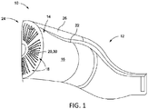
- FIG. 1 illustrated is a representative embodiment of a combustion component of a turbine system 10 having a combustor section 12 and a head end 14.
- the head end 14 is disposed at an adjacent upstream location of the combustor section 12 and includes a micromixer assembly 16.
- the micromixer assembly 16 includes a plate 17 that extends generally radially and circumferentially and has, in some embodiments, a plurality of sectors 18, each of which comprises a plurality of tubes 20.
- the combustor section 12 is defined by an outer liner 22 that extends to an upstream end 24. Spaced radially outwardly of the outer liner 22, and surrounding and enclosing the outer liner 22, is a flow sleeve 26.
- a flow of air passes upstream within an air passage defined by the outer liner 22 and the flow sleeve 26 to the upstream end 24 of the outer liner 22.
- FIG. 2 a top, cross-sectional view of the plate 17 and a tube 20 of the plurality of tubes is illustrated, showing the tube 20 disposed within a receiving aperture 30 of the plate 17.
- the plate 17 includes a plurality of receiving apertures that extend relatively axially through the plate 17 and are each configured to have a receiving diameter 32 that is dimensioned to allow the tube 20 to be inserted therein.
- the tube 20 comprises an inner diameter 34, an outer diameter 36, an inlet 38 and an outlet 40. It is the outer diameter 36 of the tube 20 that is dimensioned to be inserted within the receiving diameter 32 of the receiving aperture 30.
- a micromixer tube 20 may be adapted to receive an expander 50 that includes at least one expander head 52 having an outer diameter 54 that is closely dimensioned with that of the inner diameter 34 of the tube 20.
- the expander 50 comprises a shaft portion 56 that extends in a longitudinal direction 58 that relatively coincides with an axial direction of the turbine system 10, with the at least one expander head 52 disposed along the length thereof.
- the function of the expander head 52 is to be controllably disposed at a position within the tube 20 that is desired to form a friction weld with the receiving aperture 30 of the plate 17. It will be appreciated that there are alternate means by which a tube may be affixed into engagement within a plate aperture, and the expander means for friction welding is but one example and is thus, non-limiting with respect to the disclosure.
- brazing may be accomplished by any suitable brazing technique.
- brazing as used herein is with reference to surface treatment of a micromixer tube as substrate wherein the process does not include joining workpieces, but rather is performed to affix a braze filler material directly to the surface of the micromixer tube to achieve benefits.
- the techniques of vacuum brazing are used.
- the brazing is accomplished as a single-step vacuum brazing, at about 8 x 10 -4 torr and the brazing temperature is between about 1500° F. and about 2300° F., between about 1500° F. and about 2300° F., between about 1500° F. and about 1800° F., between about 2000° F. and about 2300° F., between about 1800° F. and about 2300° F., between about 1800° F. and about 2100° F., or any suitable combination, sub-combination, range, or sub-range therein.
- the method optionally further includes applying at least one bonding coat layer directly adjacent the micromixer tube, over which layer the brazed wear layer is applied.
- the method optionally further includes applying at least one heat resistant coat, such as a thermal barrier coating, either or both between the material of the micromixer tube and the brazed wear layer or over the brazed wear layer.
- inserting the tube into a receiving aperture of a plate is also included.
- applying a fixation means for securing engagement between the tube and the plate is further included, the means optionally including exerting a radial force on an inner wall of the tube with an expander to form at least one operable connection between an outer diameter of the tube and the receiving aperture of the plate.
Landscapes
- Engineering & Computer Science (AREA)
- Mechanical Engineering (AREA)
- Chemical & Material Sciences (AREA)
- Combustion & Propulsion (AREA)
- General Engineering & Computer Science (AREA)
- Materials Engineering (AREA)
- Chemical Kinetics & Catalysis (AREA)
- Pressure Welding/Diffusion-Bonding (AREA)
Abstract
Description
- The present invention is directed to manufactured articles, and methods of manufacturing micromixer components and articles. More particularly, embodiments of the present invention relate to wear protected components and articles, such as combustor components of turbine engines, and even more particularly to enhanced wear protected micromixer tubes and assemblies thereof with one or more micromixer plates, the micromixer tubes having wear protection for enhanced performance and reduced wear related failure.
- Turbine engines typically include one or more components that compress an incoming flow of air and deliver the compressed flow of air to a combustor that mixes the compressed flow of air with a pressurized flow of fuel and ignites the mixture to create a flow of combustion gases. Combustors of turbine systems often include a micromixer assembly that typically includes a base nozzle structure in communication with a fuel plenum, an air intake, and numerous mixing tubes forming one or more segmented mixing tube bundles. The base nozzle structure supplies a fuel to the fuel plenum. The fuel exits the fuel plenum and enters the mixing tubes. Air is directed into the mixing tubes through the air intake and mixes with the fuel to create an air/fuel mixture. The air/fuel mixture exits the mixing tubes and enters into a downstream combustion chamber. This flow of combustion gases drives the turbine to produce mechanical work for electrical power generation and the like. A turbine engine may use any of a variety of fuels and may be selected from any of a number of different turbine engines, such as those offered by General Electric Company of Schenectady, N.Y. In some particular embodiments, the micromixer assembly includes a plurality of tubes and at least a first end plate that has a plurality of holes drilled or otherwise cut into it in which a first end of each of the tubes terminates, the plurality of holes in the end plate corresponding in number to the plurality of tubes that are disposed within the apertures thereof.
- According to various methods, assembly of micromixer tubes within the plate apertures involves a process for fixing them therein in order to stabilize the assembly and minimize vibration of the tubes within the plate. In some instances, this fixation is achieved by friction welding, and in other instances, by use of a relatively expensive brazing filler, which may include gold and/or nickel. Such processes can be time consuming and expensive, and may not always achieve the desired result. Thus, during operation, vibration of the tube within the plate aperture can lead to wear that can ultimately contribute to metal loss and tube tip failure, which can in turn lead to combustor inefficiency and possible failure.
- According to an aspect of the invention, a micromixer assembly of a turbine system includes a plate having at least one aperture comprising a receiving diameter, and at least one micromixer tube having an inlet and an outlet for receiving a flow and dispersing the flow to a combustor, wherein the at least one micromixer tube includes an outer surface having an outer diameter configured to fit within the receiving diameter of the at least one plate aperture, wherein the at least one tube is adapted with a surface treatment for reducing wear, the surface treatment comprising at least a brazed wear coating.
- According to another aspect of the invention, a method of assembling a wear resistant micromixer assembly of a turbine system is provided. The method includes applying a surface treatment to at least a portion of at least one micromixer tube, the treatment comprising application of a braze alloy followed by processing to form a wear resistant brazed coating. The method optionally further includes applying at least one bonding coat layer directly adjacent the micromixer tube, over which layer the brazed wear layer is applied. The method optionally further includes applying at least one heat resistant coat, such as a thermal barrier coating, either or both between the material of the micromixer tube and the brazed wear layer or over the brazed wear layer. Also included is inserting the surface treated micromixer tube into a receiving aperture of a plate. Optionally, further included is applying a fixation means for securing engagement between the micromixer tube and the plate, the means optionally including exerting a radial force on an inner wall of the tube with an expander to form at least one operable connection between an outer diameter of the tube and the receiving aperture of the plate.
- Other features and advantages of the present invention will be apparent from the following more detailed description of the preferred embodiment, taken in conjunction with the accompanying drawings which illustrate, by way of example, the principles of the invention.
-
-
FIG. 1 is a perspective view of a turbine system having a micromixer assembly located in a head end; -
FIG. 2 is a top, cross-sectional view of a micromixer tube disposed within an aperture of a plate and an expander disposed within the micromixer tube; and, -
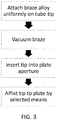
FIG. 3 is a flow diagram illustrating a method of preparing a surface treated micromixer tube and assembling the enhanced wear resistant micromixer assembly. - Provided are manufacturing methods, and articles for combustion micromixer tube wear management including micromixer tubes and assemblies. Embodiments of the present disclosure, in comparison to articles and methods that do not include one or more of the features disclosed herein, provide additional wear protection features to extend the operating lifetime of the parts, minimize the need for use of costlier materials and processes for assembly and fixation of combustor parts, permit the useful life of turbine components to be extended, permit gas turbine systems using embodiments of the turbine components to be more efficient, permit use of less costly underlying parts materials, or a combination thereof. In particular, embodiments of the present disclosure, in comparison to processes and articles that do not include one or more of the features disclosed herein, enable a significant wear reduction benefit, thereby allowing metal loss and tube tip failure, and thereby enhancing part life and continued operation of the turbine.
- Referring now to
FIG. 1 , illustrated is a representative embodiment of a combustion component of aturbine system 10 having acombustor section 12 and ahead end 14. Thehead end 14 is disposed at an adjacent upstream location of thecombustor section 12 and includes amicromixer assembly 16. Themicromixer assembly 16 includes aplate 17 that extends generally radially and circumferentially and has, in some embodiments, a plurality ofsectors 18, each of which comprises a plurality oftubes 20. Thecombustor section 12 is defined by anouter liner 22 that extends to anupstream end 24. Spaced radially outwardly of theouter liner 22, and surrounding and enclosing theouter liner 22, is aflow sleeve 26. A flow of air passes upstream within an air passage defined by theouter liner 22 and theflow sleeve 26 to theupstream end 24 of theouter liner 22. It will be appreciated that the embodiment shown is merely representative, and that other examples of combustion components are known in the art, including those with alternate features of micromixer assemblies, thus, the embodiments as shown is not limiting. - In operation of the combustor, a working fluid can flow through the passage of the
flow sleeve 26 along the outside of theouter liner 22 to provide convective cooling to theouter liner 22. When the fluid reaches the end cover of the combustor, the fluid reverses direction and flows through at least a portion of thetubes 20 where it mixes with fuel before it is injected into thecombustor section 12. Thetubes 20 generally include an upstream end that is axially separated from a downstream end, and according to the invention, as described herein below, each of thetubes 20 is brazed at least at an end that inserts into one ormore plates 17. - Referring to
FIG. 2 , a top, cross-sectional view of theplate 17 and atube 20 of the plurality of tubes is illustrated, showing thetube 20 disposed within a receiving aperture 30 of theplate 17. Theplate 17 includes a plurality of receiving apertures that extend relatively axially through theplate 17 and are each configured to have a receiving diameter 32 that is dimensioned to allow thetube 20 to be inserted therein. Specifically, thetube 20 comprises aninner diameter 34, anouter diameter 36, aninlet 38 and anoutlet 40. It is theouter diameter 36 of thetube 20 that is dimensioned to be inserted within the receiving diameter 32 of the receiving aperture 30. - In some embodiments, the
tube 20 is dimensioned and adapted to facilitate the formation of a friction weld between an outer wall portion of thetube 20 and the receiving aperture 30 of the plate. According to some such embodiments, as is shown inFIG. 2 , amicromixer tube 20 may be adapted to receive an expander 50 that includes at least oneexpander head 52 having an outer diameter 54 that is closely dimensioned with that of theinner diameter 34 of thetube 20. The expander 50 comprises ashaft portion 56 that extends in alongitudinal direction 58 that relatively coincides with an axial direction of theturbine system 10, with the at least oneexpander head 52 disposed along the length thereof. The function of theexpander head 52 is to be controllably disposed at a position within thetube 20 that is desired to form a friction weld with the receiving aperture 30 of theplate 17. It will be appreciated that there are alternate means by which a tube may be affixed into engagement within a plate aperture, and the expander means for friction welding is but one example and is thus, non-limiting with respect to the disclosure. - Each of the plurality of tubes and the plate are typically formed of a durable material that is suitable for functioning in a region having a temperature that may exceed 1,600° F. (871° C.). Such a material may comprise stainless steel and/or a nickel-based alloy, such as Hastelloy® X, the aforementioned material being discussed herein as merely illustrative and non-limiting. In various non-limiting examples, the tubes and plates may include any suitable material, for example, stainless steel, a nickel-based alloy, an iron-based alloy, or any other suitable metal or metallic material.
- In accordance with the disclosure, methods are provided for improving the wear resistance of micromixer tubes, in particular the tube ends that are engaged with one or more micromixer plates. Referring now to
FIG. 3 , a representative flow diagram of the methods according to the disclosure is provided. Brazing may be accomplished by any suitable brazing technique. And it will be appreciated that the term brazing as used herein is with reference to surface treatment of a micromixer tube as substrate wherein the process does not include joining workpieces, but rather is performed to affix a braze filler material directly to the surface of the micromixer tube to achieve benefits. In some embodiments according to the invention, the techniques of vacuum brazing are used. As used herein, vacuum brazing means and refers to a process that offers the advantages of providing clean, superior, flux-free braze joints and surfaces of high integrity and strength. The process is performed inside a vacuum chamber vessel at a pressure of about 8 x 10⁻⁴ torr, and in some embodiments, not more than 8 x 10⁻⁴ torr, wherein temperature uniformity typically in the range from about 1500° F. to about 2300° F. is maintained on the work piece under continuous heat to thereby reduce or eliminate the stress that can be introduced by other methods where heating and cooling cycles can occur. - Thus, in one embodiment, the brazing is accomplished as a single-step vacuum brazing, at about 8 x 10⁻⁴ torr and the brazing temperature is between about 1500° F. and about 2300° F., between about 1500° F. and about 2300° F., between about 1500° F. and about 1800° F., between about 2000° F. and about 2300° F., between about 1800° F. and about 2300° F., between about 1800° F. and about 2100° F., or any suitable combination, sub-combination, range, or sub-range therein. In one embodiment, the brazing duration is between about 1 minute and about 30 minutes, between about 5 minutes and about 30 minutes, between about 15 minutes and about 30 minutes, between about 20 minutes and about 30 minutes, about 10 minutes, about 15 minutes, about 20 minutes, about 30 minutes, or any suitable combination, sub-combination, range, or sub-range therein.
- According to one embodiment, the methods include applying a surface treatment to at least a portion of at least one micromixer tube, the treatment comprising a wear resistant brazed coating by application of one or a mix of powdered braze materials to all or a portion of a micromixer tube followed by vacuum brazing. In accordance with such methods, the powdered braze material comprises known or novel low melt materials, and in particular, for use with tubes formed of stainless steel, the braze powders are particularly compatible with such tube base material. It will be appreciated, of course, that other tube base materials may be used, and as such, other braze materials may be selected, which may be low melt or other than low melt, and the method of brazing may be other than vacuum brazing.
- Thus, in accordance with various embodiments, the material for the braze powders selected for the braze coat surface treatment may be any suitable brazing material, including, but not limited to, metal alloys and superalloys, including nickel and cobalt-based superalloys, alloys and combinations thereof. Suitable examples of a nickel-based alloy may have a formula (by mass) of Ni0.6715Cr0.14B0.0275Co0.1Al0.035Ta0.025Y0.001 (commercially available as Amdry DF4B from Sulzer Metco, located in Westbury, New York) or a formula (by mass) of Ni0.71Cr0.0.19.Si0.10 (commercially available as BNi-5 from many providers, including Wall Colmonoy, located in Madison Heights, Michigan). The braze layer may enable a fit tolerance between THE surface of the micromixer tube and the inner surface of the plate aperture of between about 0.0005 inches to about 0.008 inches. The braze surface treatment may fill minor gaps and surface imperfections on the tubes, and in various embodiments, the braze coat provides enhanced surface hardness imparting greater wear resistance as compared to conventional micromixer tubes that are not braze treated.
- In one example according to the disclosure, a selection of micromixer tubes were surface treated with a braze material to confer wear resistance. In such representative embodiment, a low-melt material (MM509B) suitable for brazing the micromixer tube components may be selected, having a composition, by weight, of between about 22.5% and about 24.25% Cr, up to about 0.3% Ti (for example, between about 0.15% and about 0.3%), between about 6.5% and about 7.5% W, between about 9% and about 11% Ni, between about 3% and about 4% Ta, up to about 0.65% C (for example, between about 0.55% and about 0.65%), between about 2% and about 3% B (for example, between about 2% and about 3%), about 1.3% Fe, up to about 0.4% Si, up to about 0.1% Mn, up to about 0.02% S, and a balance of cobalt. Another suitable low-melt material has a composition, by weight, of about 14% Cr, about 9% Co, about 4% Al, about 2.5% B, and a balance of nickel. Another suitable low-melt material has a composition, by weight, of about 15.3% Cr, about 10.3% Co, about 3.5% Ta, about 3.5% Al, about 2.3% B, and a balance of nickel. In yet other examples, alloys suitable for brazing according to the instant disclosure include materials selected from BN12, and BN19.
- According to such embodiments, surface treated micromixer tubes are provided with a braze surface treatment in the range from about 2 mm to 3 mm coat thickness, using the low-melt braze coating material as described above. The braze treatment confers visibly altered surface properties and provides enhanced surface hardness. In accordance with the disclosure, surface treatment of the micromixer tubes may range from about 1 mm to about 5 mm thickness, and in various embodiments, the thickness may be 1 mm, 2 mm, 3 mm, 4 mm, and 5 mm, and fractions there between in the amount of from 0.1 MM to 0.5 mm.
- It will be appreciated that the braze materials may be used alone, or in combinations. Accordingly, in some embodiments, the braze powders used herein may include a combination of MM509B with BN12, or the combination of MM509B with BN 19.
- The method optionally further includes applying at least one bonding coat layer directly adjacent the micromixer tube, over which layer the brazed wear layer is applied. The method optionally further includes applying at least one heat resistant coat, such as a thermal barrier coating, either or both between the material of the micromixer tube and the brazed wear layer or over the brazed wear layer. Also included is inserting the tube into a receiving aperture of a plate. Optionally, further included is applying a fixation means for securing engagement between the tube and the plate, the means optionally including exerting a radial force on an inner wall of the tube with an expander to form at least one operable connection between an outer diameter of the tube and the receiving aperture of the plate.
- A technical advantage of the present surface treatment for micromixer tubes includes greater longevity for the mixing tubes, and reduced failure rate of the tubes and the combustor. Another advantage is reduction of cost associated with repairs.
- While the invention has been described with reference to a preferred embodiment, it will be understood by those skilled in the art that various changes may be made and equivalents may be substituted for elements thereof without departing from the scope of the invention. In addition, many modifications may be made to adapt a particular situation or material to the teachings of the invention without departing from the essential scope thereof. Therefore, it is intended that the invention not be limited to the particular embodiment disclosed as the best mode contemplated for carrying out this invention, but that the invention will include all embodiments falling within the scope of the appended claims.
Claims (15)
- A micromixer assembly (16) of a turbine system (10) comprising:a plate (17) having at least one aperture (30) having a receiving diameter (32);at least one micromixer tube (20) having an inlet (38) and an outlet (40) for receiving a flow and dispersing the flow to a combustor (12), and having an outer surface having a diameter (36) configured to fit within the receiving diameter (32) of the at least one plate (17) aperture (30), the at least one micromixer tube (20) comprising on at least a portion of its outer surface (36) a wear resistant treatment; the at least one micromixer tube (20) being inserted through the plate (17) aperture (30) and optionally operably coupled at a location on its outer surface (36) to the plate (17) at the at least one aperture (30).
- The micromixer assembly (16) of claim 1, comprising a plurality of plate (17) apertures (30) and a plurality of micromixer tubes (20) inserted therethrough.
- The micromixer assembly (16) of claims 1 or 2, wherein one or more of the at least one micromixer tube (20) is operably coupled to the plate (17).
- The micromixer assembly (16) of any of the claims 1 to 3, wherein the mode of coupling between the one or more of the at least one micromixer tube (20) and the plate (17) is brazing.
- The micromixer assembly (16) of any of the claims 1 to 3, wherein the mode of coupling between the one or more of the at least one micromixer tube (20) and the plate (17) is friction welding.
- The micromixer assembly (16) of any of the claims 1 to 5, wherein the surface treatment comprises a protective coating.
- A method of assembling a micromixer assembly (16) of a turbine system (10) comprising: applying a surface treatment wear layer to at least a portion of at least one micromixer tube (20), the treatment comprising application of a braze alloy powder followed by vacuum braze processing to form a wear resistant brazed coating, inserting the surface treated at least one micromixer tube (20) into a receiving aperture (30) of a plate (17), and optionally securing the micromixer tube (20) and the plate (17).
- The method of assembling a micromixer assembly (16) of a turbine system (10) according to claim 7, wherein the at least one micromixer tube (20) comprises a material selected from stainless steel and a nickel-based alloy.
- The method of assembling a micromixer assembly (16) of a turbine system (10) according to claims 7 or 8, wherein the at least one micromixer tube (20) is operably coupled to the plate (17).
- The method of assembling a micromixer assembly (16) of a turbine system (10) according to any of the claims 7 to 9, wherein the mode of coupling between the at least one micromixer tube (20) and the plate (17) brazing.
- The method of assembling a micromixer assembly (16) of a turbine system (10) according to claim 10, wherein the mode of coupling between the at least one micromixer tube (20) and the plate (17) is vacuum brazing.
- The method of assembling a micromixer assembly (16) of a turbine system (10) according to any of the claims 7 to 9, wherein the mode of coupling between the at least one micromixer tube (20) and the plate (17) is friction welding.
- The method of assembling a micromixer assembly (16) of a turbine system (10) according to any of the claims 7 to 12, wherein the steps are repeated for a plurality of micromixer tubes (20).
- The method of assembling a micromixer assembly (16) of a turbine system (10) according to claims 12 or 13, wherein friction welding is achieved by exerting a radial force on an inner wall (34) of the tube (20) with an expander (50) to form at least one operable connection between the outer surface (36) of the at least one micromixer tube (20) and the receiving aperture (30) of the plate (17).
- The method of assembling a micromixer assembly (16) of a turbine system (10) according to any of the claims 7 to 14, further including applying one or more of a bond coat layer and a thermal barrier coating, either or both between the at least one micromixer tube (20) and the surface treatment wear layer.
Applications Claiming Priority (1)
| Application Number | Priority Date | Filing Date | Title |
|---|---|---|---|
| US15/427,831 US10571126B2 (en) | 2017-02-08 | 2017-02-08 | Method to provide a braze coating with wear property on micromixer tubes |
Publications (2)
| Publication Number | Publication Date |
|---|---|
| EP3361160A1 true EP3361160A1 (en) | 2018-08-15 |
| EP3361160B1 EP3361160B1 (en) | 2025-03-26 |
Family
ID=61167978
Family Applications (1)
| Application Number | Title | Priority Date | Filing Date |
|---|---|---|---|
| EP18155310.8A Active EP3361160B1 (en) | 2017-02-08 | 2018-02-06 | Method to provide a braze coating with wear property on micromixer tubes |
Country Status (3)
| Country | Link |
|---|---|
| US (1) | US10571126B2 (en) |
| EP (1) | EP3361160B1 (en) |
| JP (1) | JP7536419B2 (en) |
Families Citing this family (2)
| Publication number | Priority date | Publication date | Assignee | Title |
|---|---|---|---|---|
| CN110369980B (en) * | 2019-08-16 | 2024-08-20 | 喻杰 | Preparation method of wear-resistant layer on inner wall of hole capable of improving product qualification rate |
| US11426822B2 (en) | 2020-12-03 | 2022-08-30 | General Electric Company | Braze composition and process of using |
Citations (5)
| Publication number | Priority date | Publication date | Assignee | Title |
|---|---|---|---|---|
| EP1065297A2 (en) * | 1999-06-29 | 2001-01-03 | General Electric Company | A method of providing wear-resistant coatings, and related articles |
| GB2445576A (en) * | 2007-01-11 | 2008-07-16 | Rolls Royce Plc | Igniter plug housing arrangement |
| US20130199193A1 (en) * | 2009-12-15 | 2013-08-08 | Massimo Giannozzi | Tungsten carbide inserts and method |
| US20140212208A1 (en) * | 2013-01-31 | 2014-07-31 | General Electric Company | Brazing process and plate assembly |
| US20150165568A1 (en) * | 2013-12-13 | 2015-06-18 | General Electric Company | Method for repairing a bundled tube fuel injector |
Family Cites Families (8)
| Publication number | Priority date | Publication date | Assignee | Title |
|---|---|---|---|---|
| US20060275106A1 (en) * | 2005-06-07 | 2006-12-07 | Ioannis Alvanos | Blade neck fluid seal |
| US9163839B2 (en) | 2012-03-19 | 2015-10-20 | General Electric Company | Micromixer combustion head end assembly |
| US9546789B2 (en) * | 2013-03-15 | 2017-01-17 | General Electric Company | System having a multi-tube fuel nozzle |
| US9303873B2 (en) * | 2013-03-15 | 2016-04-05 | General Electric Company | System having a multi-tube fuel nozzle with a fuel nozzle housing |
| US9784452B2 (en) * | 2013-03-15 | 2017-10-10 | General Electric Company | System having a multi-tube fuel nozzle with an aft plate assembly |
| US9316397B2 (en) * | 2013-03-15 | 2016-04-19 | General Electric Company | System and method for sealing a fuel nozzle |
| US9291352B2 (en) * | 2013-03-15 | 2016-03-22 | General Electric Company | System having a multi-tube fuel nozzle with an inlet flow conditioner |
| US20150167983A1 (en) * | 2013-12-13 | 2015-06-18 | General Electric Company | Bundled tube fuel injector tube tip |
-
2017
- 2017-02-08 US US15/427,831 patent/US10571126B2/en active Active
-
2018
- 2018-02-06 JP JP2018018794A patent/JP7536419B2/en active Active
- 2018-02-06 EP EP18155310.8A patent/EP3361160B1/en active Active
Patent Citations (5)
| Publication number | Priority date | Publication date | Assignee | Title |
|---|---|---|---|---|
| EP1065297A2 (en) * | 1999-06-29 | 2001-01-03 | General Electric Company | A method of providing wear-resistant coatings, and related articles |
| GB2445576A (en) * | 2007-01-11 | 2008-07-16 | Rolls Royce Plc | Igniter plug housing arrangement |
| US20130199193A1 (en) * | 2009-12-15 | 2013-08-08 | Massimo Giannozzi | Tungsten carbide inserts and method |
| US20140212208A1 (en) * | 2013-01-31 | 2014-07-31 | General Electric Company | Brazing process and plate assembly |
| US20150165568A1 (en) * | 2013-12-13 | 2015-06-18 | General Electric Company | Method for repairing a bundled tube fuel injector |
Also Published As
| Publication number | Publication date |
|---|---|
| JP2018169150A (en) | 2018-11-01 |
| US20180224124A1 (en) | 2018-08-09 |
| EP3361160B1 (en) | 2025-03-26 |
| US10571126B2 (en) | 2020-02-25 |
| JP7536419B2 (en) | 2024-08-20 |
Similar Documents
| Publication | Publication Date | Title |
|---|---|---|
| JP7463359B2 (en) | Turbomachinery blade tip installation | |
| CA2645380C (en) | Monolithic and bi-metallic turbine blade dampers and method of manufacture | |
| EP1442829A2 (en) | Method of repairing a stationary shroud of a gas turbine engine using laser cladding | |
| US6679680B2 (en) | Built-up gas turbine component and its fabrication | |
| EP1416063A1 (en) | Method of repairing a stationary shroud of a gas turbine engine using plasma transferred arc welding | |
| EP3363585B1 (en) | A manufactured article and method | |
| CN101219511A (en) | Turbine component with repaired seal joint and related method | |
| EP2762256B1 (en) | Brazing process | |
| EP3306038A1 (en) | Aft frame for a combustor | |
| EP3361160B1 (en) | Method to provide a braze coating with wear property on micromixer tubes | |
| JP2018169150A5 (en) | ||
| EP3395494A1 (en) | Treated turbine diaphragm and method for treating a turbine diaphragm | |
| US6527165B1 (en) | Method of making an environmental resistant brazed assembly including a wear resistant surface portion | |
| KR102851758B1 (en) | A closure element having an extension to the internal passage of the component | |
| JP7451512B2 (en) | Airfoil coupon installation | |
| EP4513088A1 (en) | Methods of repairing tubes in bundled tube fuel injectors | |
| US20180156462A1 (en) | Fuel Nozzle Assembly with Micro-Channel Cooling | |
| CN106415133B (en) | Combustor assembly for gas turbine engine with braze layer with centerline eutectic zone | |
| JPH07286730A (en) | Flame stabilizer for gas turbine combustor |
Legal Events
| Date | Code | Title | Description |
|---|---|---|---|
| PUAI | Public reference made under article 153(3) epc to a published international application that has entered the european phase |
Free format text: ORIGINAL CODE: 0009012 |
|
| STAA | Information on the status of an ep patent application or granted ep patent |
Free format text: STATUS: THE APPLICATION HAS BEEN PUBLISHED |
|
| AK | Designated contracting states |
Kind code of ref document: A1 Designated state(s): AL AT BE BG CH CY CZ DE DK EE ES FI FR GB GR HR HU IE IS IT LI LT LU LV MC MK MT NL NO PL PT RO RS SE SI SK SM TR |
|
| AX | Request for extension of the european patent |
Extension state: BA ME |
|
| STAA | Information on the status of an ep patent application or granted ep patent |
Free format text: STATUS: REQUEST FOR EXAMINATION WAS MADE |
|
| 17P | Request for examination filed |
Effective date: 20190215 |
|
| RBV | Designated contracting states (corrected) |
Designated state(s): AL AT BE BG CH CY CZ DE DK EE ES FI FR GB GR HR HU IE IS IT LI LT LU LV MC MK MT NL NO PL PT RO RS SE SI SK SM TR |
|
| STAA | Information on the status of an ep patent application or granted ep patent |
Free format text: STATUS: EXAMINATION IS IN PROGRESS |
|
| 17Q | First examination report despatched |
Effective date: 20200317 |
|
| RAP1 | Party data changed (applicant data changed or rights of an application transferred) |
Owner name: GENERAL ELECTRIC TECHNOLOGY GMBH |
|
| GRAP | Despatch of communication of intention to grant a patent |
Free format text: ORIGINAL CODE: EPIDOSNIGR1 |
|
| STAA | Information on the status of an ep patent application or granted ep patent |
Free format text: STATUS: GRANT OF PATENT IS INTENDED |
|
| INTG | Intention to grant announced |
Effective date: 20241017 |
|
| GRAS | Grant fee paid |
Free format text: ORIGINAL CODE: EPIDOSNIGR3 |
|
| GRAA | (expected) grant |
Free format text: ORIGINAL CODE: 0009210 |
|
| STAA | Information on the status of an ep patent application or granted ep patent |
Free format text: STATUS: THE PATENT HAS BEEN GRANTED |
|
| AK | Designated contracting states |
Kind code of ref document: B1 Designated state(s): AL AT BE BG CH CY CZ DE DK EE ES FI FR GB GR HR HU IE IS IT LI LT LU LV MC MK MT NL NO PL PT RO RS SE SI SK SM TR |
|
| REG | Reference to a national code |
Ref country code: GB Ref legal event code: FG4D |
|
| REG | Reference to a national code |
Ref country code: CH Ref legal event code: EP |
|
| REG | Reference to a national code |
Ref country code: DE Ref legal event code: R096 Ref document number: 602018080404 Country of ref document: DE |
|
| REG | Reference to a national code |
Ref country code: IE Ref legal event code: FG4D |
|
| PG25 | Lapsed in a contracting state [announced via postgrant information from national office to epo] |
Ref country code: RS Free format text: LAPSE BECAUSE OF FAILURE TO SUBMIT A TRANSLATION OF THE DESCRIPTION OR TO PAY THE FEE WITHIN THE PRESCRIBED TIME-LIMIT Effective date: 20250626 |
|
| PG25 | Lapsed in a contracting state [announced via postgrant information from national office to epo] |
Ref country code: FI Free format text: LAPSE BECAUSE OF FAILURE TO SUBMIT A TRANSLATION OF THE DESCRIPTION OR TO PAY THE FEE WITHIN THE PRESCRIBED TIME-LIMIT Effective date: 20250326 |
|
| REG | Reference to a national code |
Ref country code: LT Ref legal event code: MG9D |
|
| PG25 | Lapsed in a contracting state [announced via postgrant information from national office to epo] |
Ref country code: NO Free format text: LAPSE BECAUSE OF FAILURE TO SUBMIT A TRANSLATION OF THE DESCRIPTION OR TO PAY THE FEE WITHIN THE PRESCRIBED TIME-LIMIT Effective date: 20250626 |
|
| PG25 | Lapsed in a contracting state [announced via postgrant information from national office to epo] |
Ref country code: HR Free format text: LAPSE BECAUSE OF FAILURE TO SUBMIT A TRANSLATION OF THE DESCRIPTION OR TO PAY THE FEE WITHIN THE PRESCRIBED TIME-LIMIT Effective date: 20250326 |
|
| PG25 | Lapsed in a contracting state [announced via postgrant information from national office to epo] |
Ref country code: LV Free format text: LAPSE BECAUSE OF FAILURE TO SUBMIT A TRANSLATION OF THE DESCRIPTION OR TO PAY THE FEE WITHIN THE PRESCRIBED TIME-LIMIT Effective date: 20250326 |
|
| PG25 | Lapsed in a contracting state [announced via postgrant information from national office to epo] |
Ref country code: GR Free format text: LAPSE BECAUSE OF FAILURE TO SUBMIT A TRANSLATION OF THE DESCRIPTION OR TO PAY THE FEE WITHIN THE PRESCRIBED TIME-LIMIT Effective date: 20250627 Ref country code: BG Free format text: LAPSE BECAUSE OF FAILURE TO SUBMIT A TRANSLATION OF THE DESCRIPTION OR TO PAY THE FEE WITHIN THE PRESCRIBED TIME-LIMIT Effective date: 20250326 |
|
| REG | Reference to a national code |
Ref country code: NL Ref legal event code: MP Effective date: 20250326 |
|
| PG25 | Lapsed in a contracting state [announced via postgrant information from national office to epo] |
Ref country code: NL Free format text: LAPSE BECAUSE OF FAILURE TO SUBMIT A TRANSLATION OF THE DESCRIPTION OR TO PAY THE FEE WITHIN THE PRESCRIBED TIME-LIMIT Effective date: 20250326 |
|
| PG25 | Lapsed in a contracting state [announced via postgrant information from national office to epo] |
Ref country code: SE Free format text: LAPSE BECAUSE OF FAILURE TO SUBMIT A TRANSLATION OF THE DESCRIPTION OR TO PAY THE FEE WITHIN THE PRESCRIBED TIME-LIMIT Effective date: 20250326 |
|
| REG | Reference to a national code |
Ref country code: AT Ref legal event code: MK05 Ref document number: 1779293 Country of ref document: AT Kind code of ref document: T Effective date: 20250326 |
|
| RAP4 | Party data changed (patent owner data changed or rights of a patent transferred) |
Owner name: GE VERNOVA TECHNOLOGY GMBH |
|
| PG25 | Lapsed in a contracting state [announced via postgrant information from national office to epo] |
Ref country code: SM Free format text: LAPSE BECAUSE OF FAILURE TO SUBMIT A TRANSLATION OF THE DESCRIPTION OR TO PAY THE FEE WITHIN THE PRESCRIBED TIME-LIMIT Effective date: 20250326 |
|
| PG25 | Lapsed in a contracting state [announced via postgrant information from national office to epo] |
Ref country code: ES Free format text: LAPSE BECAUSE OF FAILURE TO SUBMIT A TRANSLATION OF THE DESCRIPTION OR TO PAY THE FEE WITHIN THE PRESCRIBED TIME-LIMIT Effective date: 20250326 Ref country code: PT Free format text: LAPSE BECAUSE OF FAILURE TO SUBMIT A TRANSLATION OF THE DESCRIPTION OR TO PAY THE FEE WITHIN THE PRESCRIBED TIME-LIMIT Effective date: 20250728 |
|
| PG25 | Lapsed in a contracting state [announced via postgrant information from national office to epo] |
Ref country code: PL Free format text: LAPSE BECAUSE OF FAILURE TO SUBMIT A TRANSLATION OF THE DESCRIPTION OR TO PAY THE FEE WITHIN THE PRESCRIBED TIME-LIMIT Effective date: 20250326 |
|
| PG25 | Lapsed in a contracting state [announced via postgrant information from national office to epo] |
Ref country code: AT Free format text: LAPSE BECAUSE OF FAILURE TO SUBMIT A TRANSLATION OF THE DESCRIPTION OR TO PAY THE FEE WITHIN THE PRESCRIBED TIME-LIMIT Effective date: 20250326 |
|
| PG25 | Lapsed in a contracting state [announced via postgrant information from national office to epo] |
Ref country code: EE Free format text: LAPSE BECAUSE OF FAILURE TO SUBMIT A TRANSLATION OF THE DESCRIPTION OR TO PAY THE FEE WITHIN THE PRESCRIBED TIME-LIMIT Effective date: 20250326 |
|
| PG25 | Lapsed in a contracting state [announced via postgrant information from national office to epo] |
Ref country code: RO Free format text: LAPSE BECAUSE OF FAILURE TO SUBMIT A TRANSLATION OF THE DESCRIPTION OR TO PAY THE FEE WITHIN THE PRESCRIBED TIME-LIMIT Effective date: 20250326 |
|
| PG25 | Lapsed in a contracting state [announced via postgrant information from national office to epo] |
Ref country code: SK Free format text: LAPSE BECAUSE OF FAILURE TO SUBMIT A TRANSLATION OF THE DESCRIPTION OR TO PAY THE FEE WITHIN THE PRESCRIBED TIME-LIMIT Effective date: 20250326 |
|
| PG25 | Lapsed in a contracting state [announced via postgrant information from national office to epo] |
Ref country code: IS Free format text: LAPSE BECAUSE OF FAILURE TO SUBMIT A TRANSLATION OF THE DESCRIPTION OR TO PAY THE FEE WITHIN THE PRESCRIBED TIME-LIMIT Effective date: 20250726 |
|
| REG | Reference to a national code |
Ref country code: DE Ref legal event code: R097 Ref document number: 602018080404 Country of ref document: DE |
|
| PG25 | Lapsed in a contracting state [announced via postgrant information from national office to epo] |
Ref country code: DK Free format text: LAPSE BECAUSE OF FAILURE TO SUBMIT A TRANSLATION OF THE DESCRIPTION OR TO PAY THE FEE WITHIN THE PRESCRIBED TIME-LIMIT Effective date: 20250326 |
|
| PG25 | Lapsed in a contracting state [announced via postgrant information from national office to epo] |
Ref country code: CZ Free format text: LAPSE BECAUSE OF FAILURE TO SUBMIT A TRANSLATION OF THE DESCRIPTION OR TO PAY THE FEE WITHIN THE PRESCRIBED TIME-LIMIT Effective date: 20250326 |
|
| PLBE | No opposition filed within time limit |
Free format text: ORIGINAL CODE: 0009261 |
|
| STAA | Information on the status of an ep patent application or granted ep patent |
Free format text: STATUS: NO OPPOSITION FILED WITHIN TIME LIMIT |
|
| REG | Reference to a national code |
Ref country code: CH Ref legal event code: L10 Free format text: ST27 STATUS EVENT CODE: U-0-0-L10-L00 (AS PROVIDED BY THE NATIONAL OFFICE) Effective date: 20260211 |
|
| REG | Reference to a national code |
Ref country code: CH Ref legal event code: U11 Free format text: ST27 STATUS EVENT CODE: U-0-0-U10-U11 (AS PROVIDED BY THE NATIONAL OFFICE) Effective date: 20260301 |
|
| 26N | No opposition filed |
Effective date: 20260105 |
|
| PGFP | Annual fee paid to national office [announced via postgrant information from national office to epo] |
Ref country code: GB Payment date: 20260121 Year of fee payment: 9 |
|
| PGFP | Annual fee paid to national office [announced via postgrant information from national office to epo] |
Ref country code: DE Payment date: 20260121 Year of fee payment: 9 |
|
| PGFP | Annual fee paid to national office [announced via postgrant information from national office to epo] |
Ref country code: IT Payment date: 20260121 Year of fee payment: 9 |
|
| PGFP | Annual fee paid to national office [announced via postgrant information from national office to epo] |
Ref country code: FR Payment date: 20260121 Year of fee payment: 9 |
|
| PGFP | Annual fee paid to national office [announced via postgrant information from national office to epo] |
Ref country code: CH Payment date: 20260301 Year of fee payment: 9 |
|
| PG25 | Lapsed in a contracting state [announced via postgrant information from national office to epo] |
Ref country code: LT Free format text: LAPSE BECAUSE OF FAILURE TO SUBMIT A TRANSLATION OF THE DESCRIPTION OR TO PAY THE FEE WITHIN THE PRESCRIBED TIME-LIMIT Effective date: 20250326 |