EP2762256B1 - Brazing process - Google Patents
Brazing process Download PDFInfo
- Publication number
- EP2762256B1 EP2762256B1 EP14153184.8A EP14153184A EP2762256B1 EP 2762256 B1 EP2762256 B1 EP 2762256B1 EP 14153184 A EP14153184 A EP 14153184A EP 2762256 B1 EP2762256 B1 EP 2762256B1
- Authority
- EP
- European Patent Office
- Prior art keywords
- brazing
- braze
- brazable
- component
- temperature
- Prior art date
- Legal status (The legal status is an assumption and is not a legal conclusion. Google has not performed a legal analysis and makes no representation as to the accuracy of the status listed.)
- Active
Links
- 238000005219 brazing Methods 0.000 title claims description 50
- 238000000034 method Methods 0.000 title claims description 28
- 239000011888 foil Substances 0.000 claims description 27
- 238000005245 sintering Methods 0.000 claims description 8
- 238000003466 welding Methods 0.000 claims description 5
- 238000005520 cutting process Methods 0.000 claims description 2
- PXHVJJICTQNCMI-UHFFFAOYSA-N Nickel Chemical compound [Ni] PXHVJJICTQNCMI-UHFFFAOYSA-N 0.000 description 20
- XEEYBQQBJWHFJM-UHFFFAOYSA-N iron Substances [Fe] XEEYBQQBJWHFJM-UHFFFAOYSA-N 0.000 description 11
- 229910052759 nickel Inorganic materials 0.000 description 11
- 239000000956 alloy Substances 0.000 description 9
- 229910045601 alloy Inorganic materials 0.000 description 9
- 239000012530 fluid Substances 0.000 description 8
- 239000000463 material Substances 0.000 description 7
- 229910052742 iron Inorganic materials 0.000 description 6
- 229910052804 chromium Inorganic materials 0.000 description 5
- 239000011651 chromium Substances 0.000 description 5
- 238000007747 plating Methods 0.000 description 5
- 229910052710 silicon Inorganic materials 0.000 description 4
- 239000000758 substrate Substances 0.000 description 4
- OKTJSMMVPCPJKN-UHFFFAOYSA-N Carbon Chemical compound [C] OKTJSMMVPCPJKN-UHFFFAOYSA-N 0.000 description 3
- VYZAMTAEIAYCRO-UHFFFAOYSA-N Chromium Chemical compound [Cr] VYZAMTAEIAYCRO-UHFFFAOYSA-N 0.000 description 3
- 238000000429 assembly Methods 0.000 description 3
- 230000000712 assembly Effects 0.000 description 3
- 229910052799 carbon Inorganic materials 0.000 description 3
- 239000000446 fuel Substances 0.000 description 3
- WPBNNNQJVZRUHP-UHFFFAOYSA-L manganese(2+);methyl n-[[2-(methoxycarbonylcarbamothioylamino)phenyl]carbamothioyl]carbamate;n-[2-(sulfidocarbothioylamino)ethyl]carbamodithioate Chemical compound [Mn+2].[S-]C(=S)NCCNC([S-])=S.COC(=O)NC(=S)NC1=CC=CC=C1NC(=S)NC(=O)OC WPBNNNQJVZRUHP-UHFFFAOYSA-L 0.000 description 3
- 239000000203 mixture Substances 0.000 description 3
- 239000010703 silicon Substances 0.000 description 3
- IJGRMHOSHXDMSA-UHFFFAOYSA-N Atomic nitrogen Chemical compound N#N IJGRMHOSHXDMSA-UHFFFAOYSA-N 0.000 description 2
- NINIDFKCEFEMDL-UHFFFAOYSA-N Sulfur Chemical compound [S] NINIDFKCEFEMDL-UHFFFAOYSA-N 0.000 description 2
- 239000011248 coating agent Substances 0.000 description 2
- 238000000576 coating method Methods 0.000 description 2
- 238000002485 combustion reaction Methods 0.000 description 2
- 230000001419 dependent effect Effects 0.000 description 2
- 238000007772 electroless plating Methods 0.000 description 2
- 238000009713 electroplating Methods 0.000 description 2
- 238000003754 machining Methods 0.000 description 2
- 239000007769 metal material Substances 0.000 description 2
- 229910052717 sulfur Inorganic materials 0.000 description 2
- 239000011593 sulfur Substances 0.000 description 2
- RYGMFSIKBFXOCR-UHFFFAOYSA-N Copper Chemical compound [Cu] RYGMFSIKBFXOCR-UHFFFAOYSA-N 0.000 description 1
- ZOKXTWBITQBERF-UHFFFAOYSA-N Molybdenum Chemical compound [Mo] ZOKXTWBITQBERF-UHFFFAOYSA-N 0.000 description 1
- OAICVXFJPJFONN-UHFFFAOYSA-N Phosphorus Chemical compound [P] OAICVXFJPJFONN-UHFFFAOYSA-N 0.000 description 1
- 240000007643 Phytolacca americana Species 0.000 description 1
- 239000000654 additive Substances 0.000 description 1
- 239000000853 adhesive Substances 0.000 description 1
- 230000001070 adhesive effect Effects 0.000 description 1
- 238000004891 communication Methods 0.000 description 1
- 238000007596 consolidation process Methods 0.000 description 1
- 238000001816 cooling Methods 0.000 description 1
- 229910052802 copper Inorganic materials 0.000 description 1
- 239000010949 copper Substances 0.000 description 1
- 238000009792 diffusion process Methods 0.000 description 1
- 239000003085 diluting agent Substances 0.000 description 1
- -1 for example Substances 0.000 description 1
- 230000000977 initiatory effect Effects 0.000 description 1
- 238000003780 insertion Methods 0.000 description 1
- 230000037431 insertion Effects 0.000 description 1
- 238000007689 inspection Methods 0.000 description 1
- 238000004519 manufacturing process Methods 0.000 description 1
- 230000000873 masking effect Effects 0.000 description 1
- 229910052751 metal Inorganic materials 0.000 description 1
- 238000012986 modification Methods 0.000 description 1
- 230000004048 modification Effects 0.000 description 1
- 229910052750 molybdenum Inorganic materials 0.000 description 1
- 239000011733 molybdenum Substances 0.000 description 1
- 229910052757 nitrogen Inorganic materials 0.000 description 1
- 239000002245 particle Substances 0.000 description 1
- 229910052698 phosphorus Inorganic materials 0.000 description 1
- 239000011574 phosphorus Substances 0.000 description 1
- 239000010935 stainless steel Substances 0.000 description 1
- 229910001220 stainless steel Inorganic materials 0.000 description 1
- 238000011144 upstream manufacturing Methods 0.000 description 1
Images


Classifications
-
- B—PERFORMING OPERATIONS; TRANSPORTING
- B23—MACHINE TOOLS; METAL-WORKING NOT OTHERWISE PROVIDED FOR
- B23K—SOLDERING OR UNSOLDERING; WELDING; CLADDING OR PLATING BY SOLDERING OR WELDING; CUTTING BY APPLYING HEAT LOCALLY, e.g. FLAME CUTTING; WORKING BY LASER BEAM
- B23K1/00—Soldering, e.g. brazing, or unsoldering
- B23K1/20—Preliminary treatment of work or areas to be soldered, e.g. in respect of a galvanic coating
-
- B—PERFORMING OPERATIONS; TRANSPORTING
- B23—MACHINE TOOLS; METAL-WORKING NOT OTHERWISE PROVIDED FOR
- B23K—SOLDERING OR UNSOLDERING; WELDING; CLADDING OR PLATING BY SOLDERING OR WELDING; CUTTING BY APPLYING HEAT LOCALLY, e.g. FLAME CUTTING; WORKING BY LASER BEAM
- B23K1/00—Soldering, e.g. brazing, or unsoldering
- B23K1/0008—Soldering, e.g. brazing, or unsoldering specially adapted for particular articles or work
- B23K1/0012—Brazing heat exchangers
-
- B—PERFORMING OPERATIONS; TRANSPORTING
- B23—MACHINE TOOLS; METAL-WORKING NOT OTHERWISE PROVIDED FOR
- B23K—SOLDERING OR UNSOLDERING; WELDING; CLADDING OR PLATING BY SOLDERING OR WELDING; CUTTING BY APPLYING HEAT LOCALLY, e.g. FLAME CUTTING; WORKING BY LASER BEAM
- B23K1/00—Soldering, e.g. brazing, or unsoldering
- B23K1/0008—Soldering, e.g. brazing, or unsoldering specially adapted for particular articles or work
- B23K1/0018—Brazing of turbine parts
-
- B—PERFORMING OPERATIONS; TRANSPORTING
- B23—MACHINE TOOLS; METAL-WORKING NOT OTHERWISE PROVIDED FOR
- B23K—SOLDERING OR UNSOLDERING; WELDING; CLADDING OR PLATING BY SOLDERING OR WELDING; CUTTING BY APPLYING HEAT LOCALLY, e.g. FLAME CUTTING; WORKING BY LASER BEAM
- B23K1/00—Soldering, e.g. brazing, or unsoldering
- B23K1/008—Soldering within a furnace
-
- B—PERFORMING OPERATIONS; TRANSPORTING
- B23—MACHINE TOOLS; METAL-WORKING NOT OTHERWISE PROVIDED FOR
- B23K—SOLDERING OR UNSOLDERING; WELDING; CLADDING OR PLATING BY SOLDERING OR WELDING; CUTTING BY APPLYING HEAT LOCALLY, e.g. FLAME CUTTING; WORKING BY LASER BEAM
- B23K11/00—Resistance welding; Severing by resistance heating
- B23K11/10—Spot welding; Stitch welding
- B23K11/11—Spot welding
-
- B—PERFORMING OPERATIONS; TRANSPORTING
- B23—MACHINE TOOLS; METAL-WORKING NOT OTHERWISE PROVIDED FOR
- B23K—SOLDERING OR UNSOLDERING; WELDING; CLADDING OR PLATING BY SOLDERING OR WELDING; CUTTING BY APPLYING HEAT LOCALLY, e.g. FLAME CUTTING; WORKING BY LASER BEAM
- B23K37/00—Auxiliary devices or processes, not specially adapted to a procedure covered by only one of the preceding main groups
- B23K37/04—Auxiliary devices or processes, not specially adapted to a procedure covered by only one of the preceding main groups for holding or positioning work
-
- F—MECHANICAL ENGINEERING; LIGHTING; HEATING; WEAPONS; BLASTING
- F23—COMBUSTION APPARATUS; COMBUSTION PROCESSES
- F23R—GENERATING COMBUSTION PRODUCTS OF HIGH PRESSURE OR HIGH VELOCITY, e.g. GAS-TURBINE COMBUSTION CHAMBERS
- F23R3/00—Continuous combustion chambers using liquid or gaseous fuel
- F23R3/28—Continuous combustion chambers using liquid or gaseous fuel characterised by the fuel supply
- F23R3/286—Continuous combustion chambers using liquid or gaseous fuel characterised by the fuel supply having fuel-air premixing devices
-
- F—MECHANICAL ENGINEERING; LIGHTING; HEATING; WEAPONS; BLASTING
- F28—HEAT EXCHANGE IN GENERAL
- F28F—DETAILS OF HEAT-EXCHANGE AND HEAT-TRANSFER APPARATUS, OF GENERAL APPLICATION
- F28F9/00—Casings; Header boxes; Auxiliary supports for elements; Auxiliary members within casings
- F28F9/02—Header boxes; End plates
- F28F9/04—Arrangements for sealing elements into header boxes or end plates
- F28F9/16—Arrangements for sealing elements into header boxes or end plates by permanent joints, e.g. by rolling
- F28F9/18—Arrangements for sealing elements into header boxes or end plates by permanent joints, e.g. by rolling by welding
- F28F9/185—Arrangements for sealing elements into header boxes or end plates by permanent joints, e.g. by rolling by welding with additional preformed parts
-
- B—PERFORMING OPERATIONS; TRANSPORTING
- B23—MACHINE TOOLS; METAL-WORKING NOT OTHERWISE PROVIDED FOR
- B23K—SOLDERING OR UNSOLDERING; WELDING; CLADDING OR PLATING BY SOLDERING OR WELDING; CUTTING BY APPLYING HEAT LOCALLY, e.g. FLAME CUTTING; WORKING BY LASER BEAM
- B23K2103/00—Materials to be soldered, welded or cut
- B23K2103/02—Iron or ferrous alloys
- B23K2103/04—Steel or steel alloys
- B23K2103/05—Stainless steel
-
- B—PERFORMING OPERATIONS; TRANSPORTING
- B23—MACHINE TOOLS; METAL-WORKING NOT OTHERWISE PROVIDED FOR
- B23K—SOLDERING OR UNSOLDERING; WELDING; CLADDING OR PLATING BY SOLDERING OR WELDING; CUTTING BY APPLYING HEAT LOCALLY, e.g. FLAME CUTTING; WORKING BY LASER BEAM
- B23K2103/00—Materials to be soldered, welded or cut
- B23K2103/08—Non-ferrous metals or alloys
-
- B—PERFORMING OPERATIONS; TRANSPORTING
- B23—MACHINE TOOLS; METAL-WORKING NOT OTHERWISE PROVIDED FOR
- B23K—SOLDERING OR UNSOLDERING; WELDING; CLADDING OR PLATING BY SOLDERING OR WELDING; CUTTING BY APPLYING HEAT LOCALLY, e.g. FLAME CUTTING; WORKING BY LASER BEAM
- B23K2103/00—Materials to be soldered, welded or cut
- B23K2103/18—Dissimilar materials
- B23K2103/26—Alloys of Nickel and Cobalt and Chromium
-
- F—MECHANICAL ENGINEERING; LIGHTING; HEATING; WEAPONS; BLASTING
- F05—INDEXING SCHEMES RELATING TO ENGINES OR PUMPS IN VARIOUS SUBCLASSES OF CLASSES F01-F04
- F05D—INDEXING SCHEME FOR ASPECTS RELATING TO NON-POSITIVE-DISPLACEMENT MACHINES OR ENGINES, GAS-TURBINES OR JET-PROPULSION PLANTS
- F05D2230/00—Manufacture
- F05D2230/20—Manufacture essentially without removing material
- F05D2230/23—Manufacture essentially without removing material by permanently joining parts together
- F05D2230/232—Manufacture essentially without removing material by permanently joining parts together by welding
- F05D2230/237—Brazing
-
- F—MECHANICAL ENGINEERING; LIGHTING; HEATING; WEAPONS; BLASTING
- F23—COMBUSTION APPARATUS; COMBUSTION PROCESSES
- F23R—GENERATING COMBUSTION PRODUCTS OF HIGH PRESSURE OR HIGH VELOCITY, e.g. GAS-TURBINE COMBUSTION CHAMBERS
- F23R2900/00—Special features of, or arrangements for continuous combustion chambers; Combustion processes therefor
- F23R2900/00018—Manufacturing combustion chamber liners or subparts
-
- F—MECHANICAL ENGINEERING; LIGHTING; HEATING; WEAPONS; BLASTING
- F28—HEAT EXCHANGE IN GENERAL
- F28F—DETAILS OF HEAT-EXCHANGE AND HEAT-TRANSFER APPARATUS, OF GENERAL APPLICATION
- F28F2265/00—Safety or protection arrangements; Arrangements for preventing malfunction
- F28F2265/26—Safety or protection arrangements; Arrangements for preventing malfunction for allowing differential expansion between elements
-
- F—MECHANICAL ENGINEERING; LIGHTING; HEATING; WEAPONS; BLASTING
- F28—HEAT EXCHANGE IN GENERAL
- F28F—DETAILS OF HEAT-EXCHANGE AND HEAT-TRANSFER APPARATUS, OF GENERAL APPLICATION
- F28F2275/00—Fastening; Joining
- F28F2275/04—Fastening; Joining by brazing
- F28F2275/045—Fastening; Joining by brazing with particular processing steps, e.g. by allowing displacement of parts during brazing or by using a reservoir for storing brazing material
Definitions
- the present invention is directed to fabrication processes and fabricated assemblies. More particularly, the present invention is directed to brazing processes and assemblies including brazed components.
- Brazing to fabricate certain components can present challenges.
- Some components can have joints between materials and/or portions of the component that require them to be secured to one another.
- Such components are present, for example, in tube-to-plate components, such as heat exchangers and micromixers.
- brazing processes use braze paste to secure tubes to plates.
- braze paste must be manually applied, which can be expensive, can result in inconsistent placement of braze paste, can result in inconsistent quantity of the braze paste, and can often only be applied to one side of a component, which can be dependent upon capillary action of the braze paste flowing through a gap. The flow is, thus, dependent upon gap size, which can also vary.
- inconsistencies can lead to variances exceeding defined tolerances.
- expensive re-brazing steps can be employed. Avoiding such re-brazing steps would be desirable.
- US 2004/0124231 discloses a method for coating a substrate.
- the method comprises providing a substrate; attaching a preform to the substrate, the preform comprising braze alloy and wear-resistant particles; and bonding the preform to the substrate to form a wear-resistant coating.
- US-A-2008 237 312 which is regarded as the closest prior art, discloses a method for brazing tubes to fins for a heat exchanger by using a brazing material that can be in a foil shape.
- an exemplary brazing process and plate assembly for example, in comparison to brazing processes that do not include one or more of the features disclosed herein, improve yield of components within predetermined tolerances, reduce or eliminate costs associated with re-brazing, increase quality and strength of brazed joints (for example, due to increased precision of gaps), permit application of a controlled amount of braze material to a predetermined location (for example, a joint), provide about 100% first time yield, permit brazing in regions that are otherwise inaccessible (for example, for inspection), permit single-step brazing of complex assemblies, or a combination thereof.
- a brazing process 100 includes positioning a braze foil on a first workpiece (step 102), then securing the braze foil to the first workpiece (step 104), thereby forming a brazable component, then positioning a second workpiece to proximal the brazable component (step 106), and then brazing the second workpiece to the brazable component (step 108).
- the securing includes plating, tack-welding, or a combination thereof.
- the braze foil is any suitable braze material, such as a nickel-based braze alloy.
- the braze foil is a pre-sintered foil 54 as is further described below with reference to FIGS. 4-5 .
- Suitable materials include, but are not limited to, a diffusion braze alloy having, by weight, about 79.9% Ni, about 15% Cr, about 3.6% B, and about 1.5% Fe, and a boron-free braze alloy having, by weight, about 70.9% Ni, about 19% Cr, and about 10.1% Si.
- the braze foil has a predetermined braze temperature, for example, between 816°C (1500°F) and 1260°C (2300°F), between 982°C (1800°F) and 1260°C (2300°F), between 1093°C (2000°F) and 1260°C (2300°F), between 1149°C (2100°F) and 1204°C (2200°F), between 1093°C (2000°F) and 1149°C (2100°F), between 816°C (1500°F) and 982°C (1800°F), of 816°C (1500°F), of 982°C (1800°F), of 1093°C (2000°F), of 1121°C (2050°F), of 1149°C (2100°F), of 1177°C (2150°F), of any suitable combination, sub-combination, range, or sub-range therein.
- a predetermined braze temperature for example, between 816°C (1500°F) and 1260°C (2300°F), between 982°C (18
- the braze foil includes any suitable thickness permitting the brazing.
- the braze foil has a thickness of about 0.051mm (2 mils).
- the positioning of the braze foil includes cutting the braze foil to a predetermined length and/or width.
- the cut braze foil is positioned in a predetermined location, such as a joint between one or more tubes (for example, having an outer diameter, such as, about 6.35mm (1 ⁇ 4 inch) and one or more plates. Additionally or alternatively, a pre-cut braze foil having the predetermined length and/or width is used.
- the tubes and plates include any suitable material, for example, stainless steel, a nickel-based alloy, an iron-based alloy, or any other suitable metal or metallic material.
- One suitable nickel-based alloy has a composition, by weight, of about 5% iron, between about 20% and about 23% chromium, up to about 0.5% silicon, between about 8% and about 10% molybdenum, up to about 0.5% manganese, up to about 0.1% carbon, and a balance nickel.
- Another suitable nickel-based alloy has a composition, by weight, of about 15.5% chromium, about 8% iron, up to about 0.5% silicon, about 1% manganese, up to about 0.15% carbon, up to about 0.5% copper, up to about 0.015% sulfur and, a balance of nickel.
- One suitable iron-based alloy has a composition, by weight, of up to about 0.003% carbon, up to about 2% manganese, up to about 0.045% phosphorus, up to about 0.03% sulfur, up to about 0.75% silicon, about 18% to about 20% chromium, between about 8% and about 12% nickel, up to about 0.1% nitrogen, and a balance of iron.
- the securing (step 104) at least temporarily maintains the braze foil on the first workpiece in a predetermined position as the brazable component.
- Suitable techniques used for the securing (step 104) include, but are not limited to tack welding (for example, a poke tack or resistance spot weld) followed by sintering at a sintering temperature below braze temperature for the braze foil, electro plating, electroless plating, intermediate plating processes, or a combination thereof, wherein securing is for a period of being between 1 minute and 30 minutes.
- the securing maintains the braze foil and the first workpiece as the brazable component in a predetermined position, enabling the brazable component to be positioned relative to the second workpiece.
- the securing (step 104) includes plating, such as, electroless plating and/or electro plating.
- the securing (step 104) includes masking steps for preventing plating of undesirable locations, includes application of intermediate layers (for example, a pure or substantially pure nickel layer).
- the securing includes tack-welding followed by the sintering at sintering temperature.
- the sintering temperature is about 93°C (200°F) below the braze temperature, 38°C (100°F) below the braze temperature, 10°C (50°F) below the braze temperature, between 10°C (50°F) and 93°C (200°F) below the braze temperature, between 10°C (50°F) and 38°C (100°F) below the braze temperature, between 38°C (100°F) and 93°C (200°F) below the braze temperature, or any suitable combination, sub-combination, range, or sub-range therein.
- the sintering temperature is between 704°C (1300°F) and 1204°C (2200°F), between 704°C (1300°F) and 1093°C (2000°F), between 704°C (1300°F) and 982°C (1800°F), between 704°C (1300°F) and 871°C (1600°F), between 816°C (1500°F) and 982°C (1800°F), between 982°C (1800°F) and 1149°C (2100°F), or any suitable combination, sub-combination, range, or sub-range therein.
- the securing includes positioning the brazable component in a furnace for a predetermined duration, such as, between about 1 minute and about 30 minutes, between about 5 minutes and about 15 minutes, between about 5 minutes and about 10 minutes, between about 10 minutes and about 15 minutes, between about 15 minutes and about 30 minutes, about 1 minute, about 5 minutes, about 10 minutes, about 15 minutes, about 30 minutes or any suitable combination, sub-combination, range, or sub-range therein.
- a predetermined duration such as, between about 1 minute and about 30 minutes, between about 5 minutes and about 15 minutes, between about 5 minutes and about 10 minutes, between about 10 minutes and about 15 minutes, between about 15 minutes and about 30 minutes, about 1 minute, about 5 minutes, about 10 minutes, about 15 minutes, about 30 minutes or any suitable combination, sub-combination, range, or sub-range therein.
- the second workpiece is positioned (step 106) with the brazable component according to any suitable techniques permitting insertion or assembly. Suitable techniques include, but are not limited to, using mechanical connections, using fasteners, using adhesives, using interlocking parts, using slots, using fixtures, or a combination thereof.
- the brazable tube is inserted into the plate (or a plurality of plates or a portion of a plate assembly 11 as is described below with reference to FIG. 2 ), where the brazable tube is permitted to expand (for example, due to heat). The expansion locks the brazable tube into place, for example, prior to the initiation of the brazing (step 108).
- the brazing (step 108) includes any suitable technique(s) and/or operational parameters, such as a brazing temperature and/or a brazing duration. In one embodiment, the brazing (step 108) is performed without use of brazing paste. In one embodiment, the brazing (step 108) is a single-step brazing step and permits consolidation of multiple brazing steps.
- the brazing temperature is between 816°C (1500°F) and 1260°C (2300°F), between 816°C (1500°F) and 982°C (1800°F), between 1093°C (2000°F) and 1260°C (2300°F), between 982°C (1800°F) and 1260°C (2300°F), between 982°C (1800°F) and 1149°C (2100°F), or any suitable combination, sub-combination, range, or sub-range therein.
- the brazing duration is between about 1 minute and about 30 minutes, between about 5 minutes and about 30 minutes, between about 15 minutes and about 30 minutes, between about 20 minutes and about 30 minutes, about 10 minutes, about 15 minutes, about 20 minutes, about 30 minutes, or any suitable combination, sub-combination, range, or sub-range therein.
- the first workpiece is a tube 20 formed by the brazable component being a brazable tube and the second workpiece being a plate 32.
- a casing 12 generally surrounds a combustor 10 that forms at least a portion of the plate assembly 11 and contains a working fluid 14 flowing to the combustor 10.
- the casing 12 includes an end cover 16 at one end to provide an interface for supplying fuel, diluent, and/or other additives to the combustor 10.
- Fluid conduits 18 extend generally axially from the end cover 16 to the tubes 20. The fluid conduits 18 are in fluid communication with the tubes 20 and a fuel source (not shown).
- a liner 22 generally surrounds at least a portion of the tubes 20 and extends generally downstream from the tubes 20.
- the liner 22 at least partially defines a combustion chamber 24 downstream from the tubes 20.
- the casing 12 circumferentially surrounds the tubes 20 and/or the liner 22, for example, to define an annular passage 26 that at least partially surrounds the tubes 20 and the liner 22. This permits the working fluid 14 to flow through the annular passage 26 along the outside of the liner 22 to provide convective cooling to the liner 22.
- the working fluid 14 When the working fluid 14 reaches the end cover 16, the working fluid 14 reverses direction and flows through at least a portion of the tubes 20 where it mixes with the fuel before it is injected into the combustion chamber 24.
- the tubes 20 generally include an upstream end 28 axially separated from a downstream end 30.
- the tubes 20 are brazed to one or more of the plates 32.
- the plates 32 extend generally radially and circumferentially.
- FIG. 3 shows an enlarged schematic view of the plate assembly 11 in the combustor 10 shown in FIG. 2 .
- passages 42 extend generally axially through the plates 32.
- the passages 42 are of any size or shape.
- the tubes 20 extend generally axially through the plates 32. The particular shape, size, number, and arrangement of the tubes 20 correspond to operational parameters of the combustor 10.
- the plate assembly 11 includes any features suitable for micromixers, heat exchangers, and/or other applications.
- FIGS. 4-5 show enlarged schematic views of embodiments of the plate assembly 11 in the combustor 10 shown in FIG. 2 .
- the plate assembly 11 includes the pre-sintered foils 54 at least partially surrounding one or more portions of the tubes 20 and connecting the tubes 20 to the plates 32 by the brazing (step 108).
- the tubes 20 and the plates are arranged in one or more T-shaped joints, for example, about four joints, about six joints, about twelve joints, or any other suitable number.
- the pre-sintered foils 54 seal the tubes 20 from fluid leaks.
Description
- The present invention is directed to fabrication processes and fabricated assemblies. More particularly, the present invention is directed to brazing processes and assemblies including brazed components.
- Brazing to fabricate certain components can present challenges. Some components can have joints between materials and/or portions of the component that require them to be secured to one another. Such components are present, for example, in tube-to-plate components, such as heat exchangers and micromixers.
- Prior attempts to braze large amounts of such joints at one time (for example, between up to about 100 tubes being brazed to between about 2, 4, or more plates) have resulted in substantial and costly re-work. In part, such re-work is due to the tight tolerances (for example, gap ranges for nickel brazing being between about 0.0127mm (0.0005 inches) to about 0.102mm (0.004 inches). It is difficult to maintain tube and plate machining operations within these tolerances. Due to the tight tolerances, introducing additional sources of variation can be undesirable.
- Due to the machining operations preventing the introduction of additional variation, additional variation introduced by brazing is especially undesirable. Known brazing processes use braze paste to secure tubes to plates. However, such braze paste must be manually applied, which can be expensive, can result in inconsistent placement of braze paste, can result in inconsistent quantity of the braze paste, and can often only be applied to one side of a component, which can be dependent upon capillary action of the braze paste flowing through a gap. The flow is, thus, dependent upon gap size, which can also vary. These inconsistencies can lead to variances exceeding defined tolerances. To remedy such variances, expensive re-brazing steps can be employed. Avoiding such re-brazing steps would be desirable.
- A brazing process and a brazed component that do not suffer from one or more of the above drawbacks would be desirable in the art.
-
US 2004/0124231 discloses a method for coating a substrate. The method comprises providing a substrate; attaching a preform to the substrate, the preform comprising braze alloy and wear-resistant particles; and bonding the preform to the substrate to form a wear-resistant coating. -
US-A-2008 237 312 , which is regarded as the closest prior art, discloses a method for brazing tubes to fins for a heat exchanger by using a brazing material that can be in a foil shape. - Embodiments of the present invention are disclosed in relation to claims 1-10. Other features and advantages of the present invention will be apparent from the following more detailed description of the preferred embodiment, taken in conjunction with the accompanying drawings which illustrate, by way of example, the principles of the invention.
-
-
FIG. 1 shows a schematic view of an exemplary brazing process according to the disclosure. -
FIG. 2 shows a cross-sectional view of an exemplary plate assembly in a combustor according to the disclosure. -
FIG. 3 shows an enlarged view of an embodiment of the plate assembly in the combustor shown inFIG. 2 according to the disclosure. -
FIG. 4 shows an enlarged view of an embodiment of the plate assembly in the combustor shown inFIG. 2 according to the disclosure. -
FIG. 5 shows an enlarged view of an embodiment of the plate assembly in the combustor shown inFIG. 2 according to the disclosure. - Wherever possible, the same reference numbers will be used throughout the drawings to represent the same parts.
- Provided is an exemplary brazing process and plate assembly. Embodiments of the present disclosure, for example, in comparison to brazing processes that do not include one or more of the features disclosed herein, improve yield of components within predetermined tolerances, reduce or eliminate costs associated with re-brazing, increase quality and strength of brazed joints (for example, due to increased precision of gaps), permit application of a controlled amount of braze material to a predetermined location (for example, a joint), provide about 100% first time yield, permit brazing in regions that are otherwise inaccessible (for example, for inspection), permit single-step brazing of complex assemblies, or a combination thereof.
- Referring to
FIG. 1 , in one embodiment, abrazing process 100 includes positioning a braze foil on a first workpiece (step 102), then securing the braze foil to the first workpiece (step 104), thereby forming a brazable component, then positioning a second workpiece to proximal the brazable component (step 106), and then brazing the second workpiece to the brazable component (step 108). The securing (step 104) includes plating, tack-welding, or a combination thereof. - The braze foil is any suitable braze material, such as a nickel-based braze alloy. In one embodiment, the braze foil is a
pre-sintered foil 54 as is further described below with reference toFIGS. 4-5 . Suitable materials include, but are not limited to, a diffusion braze alloy having, by weight, about 79.9% Ni, about 15% Cr, about 3.6% B, and about 1.5% Fe, and a boron-free braze alloy having, by weight, about 70.9% Ni, about 19% Cr, and about 10.1% Si. In one embodiment, the braze foil has a predetermined braze temperature, for example, between 816°C (1500°F) and 1260°C (2300°F), between 982°C (1800°F) and 1260°C (2300°F), between 1093°C (2000°F) and 1260°C (2300°F), between 1149°C (2100°F) and 1204°C (2200°F), between 1093°C (2000°F) and 1149°C (2100°F), between 816°C (1500°F) and 982°C (1800°F), of 816°C (1500°F), of 982°C (1800°F), of 1093°C (2000°F), of 1121°C (2050°F), of 1149°C (2100°F), of 1177°C (2150°F), of any suitable combination, sub-combination, range, or sub-range therein. - The braze foil includes any suitable thickness permitting the brazing. In one embodiment, the braze foil has a thickness of about 0.051mm (2 mils). In one embodiment, the positioning of the braze foil (step 102) includes cutting the braze foil to a predetermined length and/or width. The cut braze foil is positioned in a predetermined location, such as a joint between one or more tubes (for example, having an outer diameter, such as, about 6.35mm (¼ inch) and one or more plates. Additionally or alternatively, a pre-cut braze foil having the predetermined length and/or width is used.
- The tubes and plates include any suitable material, for example, stainless steel, a nickel-based alloy, an iron-based alloy, or any other suitable metal or metallic material. One suitable nickel-based alloy has a composition, by weight, of about 5% iron, between about 20% and about 23% chromium, up to about 0.5% silicon, between about 8% and about 10% molybdenum, up to about 0.5% manganese, up to about 0.1% carbon, and a balance nickel. Another suitable nickel-based alloy has a composition, by weight, of about 15.5% chromium, about 8% iron, up to about 0.5% silicon, about 1% manganese, up to about 0.15% carbon, up to about 0.5% copper, up to about 0.015% sulfur and, a balance of nickel. One suitable iron-based alloy has a composition, by weight, of up to about 0.003% carbon, up to about 2% manganese, up to about 0.045% phosphorus, up to about 0.03% sulfur, up to about 0.75% silicon, about 18% to about 20% chromium, between about 8% and about 12% nickel, up to about 0.1% nitrogen, and a balance of iron.
- The securing (step 104) at least temporarily maintains the braze foil on the first workpiece in a predetermined position as the brazable component. Suitable techniques used for the securing (step 104) include, but are not limited to tack welding (for example, a poke tack or resistance spot weld) followed by sintering at a sintering temperature below braze temperature for the braze foil, electro plating, electroless plating, intermediate plating processes, or a combination thereof, wherein securing is for a period of being between 1 minute and 30 minutes.
- The securing (step 104) maintains the braze foil and the first workpiece as the brazable component in a predetermined position, enabling the brazable component to be positioned relative to the second workpiece.
- In one embodiment, the securing (step 104) includes plating, such as, electroless plating and/or electro plating. In embodiments with the plating, the securing (step 104) includes masking steps for preventing plating of undesirable locations, includes application of intermediate layers (for example, a pure or substantially pure nickel layer).
- In one embodiment, the securing (step 104) includes tack-welding followed by the sintering at sintering temperature. In one embodiment, the sintering temperature is about 93°C (200°F) below the braze temperature, 38°C (100°F) below the braze temperature, 10°C (50°F) below the braze temperature, between 10°C (50°F) and 93°C (200°F) below the braze temperature, between 10°C (50°F) and 38°C (100°F) below the braze temperature, between 38°C (100°F) and 93°C (200°F) below the braze temperature, or any suitable combination, sub-combination, range, or sub-range therein. Additionally or alternatively, the sintering temperature is between 704°C (1300°F) and 1204°C (2200°F), between 704°C (1300°F) and 1093°C (2000°F), between 704°C (1300°F) and 982°C (1800°F), between 704°C (1300°F) and 871°C (1600°F), between 816°C (1500°F) and 982°C (1800°F), between 982°C (1800°F) and 1149°C (2100°F), or any suitable combination, sub-combination, range, or sub-range therein.
- In one embodiment, the securing (step 104) includes positioning the brazable component in a furnace for a predetermined duration, such as, between about 1 minute and about 30 minutes, between about 5 minutes and about 15 minutes, between about 5 minutes and about 10 minutes, between about 10 minutes and about 15 minutes, between about 15 minutes and about 30 minutes, about 1 minute, about 5 minutes, about 10 minutes, about 15 minutes, about 30 minutes or any suitable combination, sub-combination, range, or sub-range therein.
- The second workpiece is positioned (step 106) with the brazable component according to any suitable techniques permitting insertion or assembly. Suitable techniques include, but are not limited to, using mechanical connections, using fasteners, using adhesives, using interlocking parts, using slots, using fixtures, or a combination thereof. In one embodiment with the second workpiece being a plate and the brazable component being a brazable tube, the brazable tube is inserted into the plate (or a plurality of plates or a portion of a
plate assembly 11 as is described below with reference toFIG. 2 ), where the brazable tube is permitted to expand (for example, due to heat). The expansion locks the brazable tube into place, for example, prior to the initiation of the brazing (step 108). - The brazing (step 108) includes any suitable technique(s) and/or operational parameters, such as a brazing temperature and/or a brazing duration. In one embodiment, the brazing (step 108) is performed without use of brazing paste. In one embodiment, the brazing (step 108) is a single-step brazing step and permits consolidation of multiple brazing steps. In one embodiment, the brazing temperature is between 816°C (1500°F) and 1260°C (2300°F), between 816°C (1500°F) and 982°C (1800°F), between 1093°C (2000°F) and 1260°C (2300°F), between 982°C (1800°F) and 1260°C (2300°F), between 982°C (1800°F) and 1149°C (2100°F), or any suitable combination, sub-combination, range, or sub-range therein. In one embodiment, the brazing duration is between about 1 minute and about 30 minutes, between about 5 minutes and about 30 minutes, between about 15 minutes and about 30 minutes, between about 20 minutes and about 30 minutes, about 10 minutes, about 15 minutes, about 20 minutes, about 30 minutes, or any suitable combination, sub-combination, range, or sub-range therein.
- Referring to
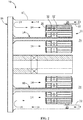
FIG. 2 , in one embodiment of theplate assembly 11 formed by theprocess 100, the first workpiece is atube 20 formed by the brazable component being a brazable tube and the second workpiece being aplate 32. For example, acasing 12 generally surrounds acombustor 10 that forms at least a portion of theplate assembly 11 and contains a workingfluid 14 flowing to thecombustor 10. Thecasing 12 includes anend cover 16 at one end to provide an interface for supplying fuel, diluent, and/or other additives to thecombustor 10.Fluid conduits 18 extend generally axially from theend cover 16 to thetubes 20. Thefluid conduits 18 are in fluid communication with thetubes 20 and a fuel source (not shown). - In one embodiment, a
liner 22 generally surrounds at least a portion of thetubes 20 and extends generally downstream from thetubes 20. Theliner 22 at least partially defines acombustion chamber 24 downstream from thetubes 20. Thecasing 12 circumferentially surrounds thetubes 20 and/or theliner 22, for example, to define anannular passage 26 that at least partially surrounds thetubes 20 and theliner 22. This permits the workingfluid 14 to flow through theannular passage 26 along the outside of theliner 22 to provide convective cooling to theliner 22. When the workingfluid 14 reaches theend cover 16, the workingfluid 14 reverses direction and flows through at least a portion of thetubes 20 where it mixes with the fuel before it is injected into thecombustion chamber 24. Thetubes 20 generally include anupstream end 28 axially separated from a downstream end 30. Thetubes 20 are brazed to one or more of theplates 32. Theplates 32 extend generally radially and circumferentially. -
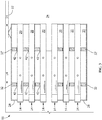
FIG. 3 shows an enlarged schematic view of theplate assembly 11 in thecombustor 10 shown inFIG. 2 . In one embodiment,passages 42 extend generally axially through theplates 32. Thepassages 42 are of any size or shape. Thetubes 20 extend generally axially through theplates 32. The particular shape, size, number, and arrangement of thetubes 20 correspond to operational parameters of thecombustor 10. - The
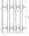
plate assembly 11 includes any features suitable for micromixers, heat exchangers, and/or other applications.FIGS. 4-5 show enlarged schematic views of embodiments of theplate assembly 11 in thecombustor 10 shown inFIG. 2 . In one embodiment, theplate assembly 11 includes the pre-sintered foils 54 at least partially surrounding one or more portions of thetubes 20 and connecting thetubes 20 to theplates 32 by the brazing (step 108). In one embodiment, thetubes 20 and the plates are arranged in one or more T-shaped joints, for example, about four joints, about six joints, about twelve joints, or any other suitable number. In a further embodiment, the pre-sintered foils 54 seal thetubes 20 from fluid leaks. - While the invention has been described with reference to a preferred embodiment, it will be understood by those skilled in the art that various changes may be made and equivalents may be substituted for elements thereof without departing from the scope of the invention. In addition, many modifications may be made to adapt a particular situation or material to the teachings of the invention without departing from the essential scope thereof. Therefore, it is intended that the invention not be limited to the particular embodiment disclosed as the best mode contemplated for carrying out this invention, but that the invention will include all embodiments falling within the scope of the appended claims.
Claims (10)
- A brazing process (100), comprising:positioning (102) a braze foil (54) on a first workpiece (20); then securing (104) the braze foil (54) to the first workpiece (20) to form a brazable component; thenpositioning (106) a second workpiece (32) proximal to the brazable component; and thenbrazing (108) the second workpiece (32) to the brazable component; characterised in that the securing (104) includes tack-welding the tack-welding being followed by sintering at a sintering temperature below the braze temperature for the braze foil.
- The brazing process (100) of claim 1, wherein the securing is in a furnace, the furnace having a temperature within 93°C (200°F) of the braze temperature for the braze foil (54).
- The brazing process (100) of any preceding claim, wherein the braze foil (54) has a braze temperature of about 1121°C (2050°F).
- The brazing process (100) of any preceding claim, further comprising cutting the braze foil (54) to a predetermined length prior to the positioning of the braze foil (54).
- The brazing process (100) of any preceding claim, wherein the brazing is at a brazing temperature, the brazing temperature being between 816°C (1500°F) and 1260°C (2300°F).
- The brazing process (100) of any preceding claim, wherein the brazing is for a brazing duration, the brazing duration being between 1 minute and 30 minutes.
- The brazing process (100) of any preceding claim, wherein the brazable component is a brazable tube (20).
- The brazing process (100) of any preceding claim, comprising installing the brazable component into a plate assembly (11).
- The brazing process (100) of claim 10, wherein the installing includes mechanical locking of the brazable component into the plate assembly (11).
- The brazing process (100) of claim 1, comprising:positioning (102) a braze foil (54) on a tube (20); thensecuring (104) the braze foil (54) to the tube (20) to form a brazable tube; thenpositioning (106) a plate (32) of a plate assembly (11) proximal to the brazable tube; and thenbrazing (108) the plate (32) to the brazable tube.
Applications Claiming Priority (1)
| Application Number | Priority Date | Filing Date | Title |
|---|---|---|---|
| US13/755,930 US8960525B2 (en) | 2013-01-31 | 2013-01-31 | Brazing process and plate assembly |
Publications (2)
| Publication Number | Publication Date |
|---|---|
| EP2762256A1 EP2762256A1 (en) | 2014-08-06 |
| EP2762256B1 true EP2762256B1 (en) | 2018-08-29 |
Family
ID=50028861
Family Applications (1)
| Application Number | Title | Priority Date | Filing Date |
|---|---|---|---|
| EP14153184.8A Active EP2762256B1 (en) | 2013-01-31 | 2014-01-30 | Brazing process |
Country Status (4)
| Country | Link |
|---|---|
| US (1) | US8960525B2 (en) |
| EP (1) | EP2762256B1 (en) |
| JP (1) | JP6334180B2 (en) |
| CN (1) | CN103962669B (en) |
Families Citing this family (8)
| Publication number | Priority date | Publication date | Assignee | Title |
|---|---|---|---|---|
| JP5568026B2 (en) * | 2011-01-20 | 2014-08-06 | トヨタ自動車株式会社 | Brazing method and brazing structure |
| GB201617840D0 (en) * | 2016-10-21 | 2016-12-07 | Rolls Royce Plc | Complementary structure |
| US10571126B2 (en) * | 2017-02-08 | 2020-02-25 | General Electric Company | Method to provide a braze coating with wear property on micromixer tubes |
| KR20190041306A (en) * | 2017-10-12 | 2019-04-22 | 주식회사 엘지화학 | Manufacturing method of different material joint body |
| CN108274087A (en) * | 2018-04-16 | 2018-07-13 | 芜湖市泰能电热器具有限公司 | A kind of application method of brazing material |
| CN109877410B (en) * | 2019-03-08 | 2021-08-06 | 西安远航真空钎焊技术有限公司 | Manufacturing method of double-cavity structure with thin-wall cooling flow channel |
| KR102460672B1 (en) * | 2021-01-06 | 2022-10-27 | 두산에너빌리티 주식회사 | Fuel nozzle, fuel nozzle module and combustor having the same |
| US11633798B1 (en) | 2021-12-02 | 2023-04-25 | General Electric Company | Braze method to modify a passage |
Family Cites Families (79)
| Publication number | Priority date | Publication date | Assignee | Title |
|---|---|---|---|---|
| US3722071A (en) * | 1971-09-30 | 1973-03-27 | Aeronca Inc | Brazing powder deposition method |
| US3768148A (en) * | 1971-12-17 | 1973-10-30 | Gen Electric | Method of joining print characters to high speed printer fingers |
| US3985282A (en) * | 1975-04-17 | 1976-10-12 | Miller Frank R | Brazing process for orthodontic assemblies |
| US4023251A (en) * | 1975-07-30 | 1977-05-17 | General Electric Company | Method of manufacture of cooled turbine or compressor buckets |
| US4223243A (en) * | 1979-05-09 | 1980-09-16 | The United States Of America As Represented By The Secretary Of The Army | Tube with bonded cathode and electrode structure and getter |
| US4224086A (en) * | 1979-05-17 | 1980-09-23 | Aluminum Company Of America | Dip brazing flux |
| US4314661A (en) | 1979-08-20 | 1982-02-09 | Allied Corporation | Homogeneous, ductile brazing foils |
| US4477012A (en) * | 1982-12-13 | 1984-10-16 | Rohr Industries, Inc. | Foil insert honeycomb sandwich brazing process and resulting structure |
| US5076875A (en) * | 1983-01-11 | 1991-12-31 | Facet Enterprises, Incorporated | Composite intermediate bonding structures |
| US4618152A (en) * | 1983-01-13 | 1986-10-21 | Thomas P. Mahoney | Honeycomb seal structure |
| US4603801A (en) * | 1984-07-24 | 1986-08-05 | The Garrett Corporation | Diffusion bonding of mechanically held components by hot isostatic pressure |
| US4620662A (en) | 1984-07-25 | 1986-11-04 | Westinghouse Electric Corp. | Two-position sleeve brazing process |
| US4716959A (en) | 1984-08-27 | 1988-01-05 | Sanden Corporation | Aluminum heat exchangers and method for producing the same |
| US5158229A (en) * | 1985-08-13 | 1992-10-27 | Allied-Signal Inc. | Low temperature, high strength, nickel, base brazing alloys |
| US4655384A (en) | 1985-10-18 | 1987-04-07 | The Babcock & Wilcox Company | Method of fabricating fiber-reinforced metal composites |
| DE3811144C1 (en) * | 1988-03-31 | 1989-12-07 | Institut Elektrosvarki Imeni E.O. Patona Akademii Nauk Ukrainskoj Ssr, Kiew/Kiev, Su | |
| US5150520A (en) * | 1989-12-14 | 1992-09-29 | The Allen Group Inc. | Heat exchanger and method of assembly thereof |
| JPH0798267B2 (en) * | 1990-10-01 | 1995-10-25 | 住友精密工業株式会社 | Brazing method |
| US5251374A (en) | 1992-09-01 | 1993-10-12 | Gary A. Halstead | Method for forming heat exchangers |
| FR2696534B1 (en) | 1992-10-02 | 1994-12-02 | Valeo Thermique Moteur Sa | Tube heat exchanger fitted with a flare. |
| US5309637A (en) * | 1992-10-13 | 1994-05-10 | Rockwell International Corporation | Method of manufacturing a micro-passage plate fin heat exchanger |
| US6262477B1 (en) * | 1993-03-19 | 2001-07-17 | Advanced Interconnect Technologies | Ball grid array electronic package |
| JPH07173611A (en) * | 1993-12-17 | 1995-07-11 | Nkk Corp | Joining method of surface treated steel sheet |
| US5617992A (en) * | 1994-06-06 | 1997-04-08 | Ford Motor Company | Soldering strip and method of using |
| JP3095624B2 (en) | 1994-07-19 | 2000-10-10 | 株式会社ボッシュオートモーティブシステム | Brazing method for flat tubes of laminated heat exchanger |
| JPH08141413A (en) * | 1994-11-28 | 1996-06-04 | Calsonic Corp | Manufacture of metallic honeycomb carrier |
| US5782638A (en) * | 1995-05-19 | 1998-07-21 | Warren, Iii; A. Daniel | Ornamental film article for dental substrate decoration and dental substrate decorated therewith |
| US5639014A (en) * | 1995-07-05 | 1997-06-17 | Johnson Matthey Electronics, Inc. | Integral solder and plated sealing cover and method of making same |
| US5823247A (en) * | 1996-08-16 | 1998-10-20 | Weibler; Walter W. | Heat exchanger and method |
| US6119920A (en) * | 1996-12-20 | 2000-09-19 | Rf Monolithics, Inc. | Method of forming an electronic package with a solder seal |
| US5956846A (en) | 1997-03-21 | 1999-09-28 | Livernois Research & Development Co. | Method and apparatus for controlled atmosphere brazing of unwelded tubes |
| US6302318B1 (en) * | 1999-06-29 | 2001-10-16 | General Electric Company | Method of providing wear-resistant coatings, and related articles |
| US20040124231A1 (en) * | 1999-06-29 | 2004-07-01 | Hasz Wayne Charles | Method for coating a substrate |
| US6451454B1 (en) * | 1999-06-29 | 2002-09-17 | General Electric Company | Turbine engine component having wear coating and method for coating a turbine engine component |
| US6387527B1 (en) * | 1999-10-04 | 2002-05-14 | General Electric Company | Method of applying a bond coating and a thermal barrier coating on a metal substrate, and related articles |
| US6355356B1 (en) * | 1999-11-23 | 2002-03-12 | General Electric Company | Coating system for providing environmental protection to a metal substrate, and related processes |
| US6129257A (en) * | 1999-12-01 | 2000-10-10 | Allison Engine Company, Inc. | High temperature brazing fixture |
| US6399217B1 (en) * | 1999-12-20 | 2002-06-04 | General Electric Company | Article surface with metal wires and method for making |
| US6511759B1 (en) * | 2000-02-07 | 2003-01-28 | Carl Schalansky | Means and method for producing multi-element laminar structures |
| JP4149119B2 (en) | 2000-06-07 | 2008-09-10 | カルソニックカンセイ株式会社 | Metal carrier brazing material feeder |
| US6749104B2 (en) | 2000-09-15 | 2004-06-15 | Anatol Rabinkin | Heat exchanger manufacturing methods and brazing filler metal compositions useful therein, characterized by low nickel leaching rates |
| US6551421B1 (en) | 2000-11-20 | 2003-04-22 | Honeywell International Inc. | Brazing foil performs and their use in the manufacture of heat exchangers |
| US6544623B1 (en) * | 2000-11-29 | 2003-04-08 | George C. P. Straza | Honeycomb cell structure and method of manufacture |
| US6426152B1 (en) * | 2000-12-14 | 2002-07-30 | General Electric Company | Salvaged castings and methods of salvaging castings with defective cast cooling bumps |
| SE519062C2 (en) | 2001-05-03 | 2003-01-07 | Alfa Laval Corp Ab | Ways of soldering thin heat exchanger plates and soldered plate heat exchangers prepared according to the method |
| US6700913B2 (en) * | 2001-05-29 | 2004-03-02 | Northrop Grumman Corporation | Low cost high integrity diode laser array |
| US6871774B2 (en) | 2002-01-04 | 2005-03-29 | Triumph Brands, Inc. | Aluminum tubular heat exchanger and method of construction |
| US6655147B2 (en) * | 2002-04-10 | 2003-12-02 | General Electric Company | Annular one-piece corrugated liner for combustor of a gas turbine engine |
| US6921014B2 (en) * | 2002-05-07 | 2005-07-26 | General Electric Company | Method for forming a channel on the surface of a metal substrate |
| US20040056071A1 (en) * | 2002-09-25 | 2004-03-25 | Honeywell International, Inc. | Adhesive laminated braze sheet |
| US20040155096A1 (en) * | 2003-02-07 | 2004-08-12 | General Electric Company | Diamond tool inserts pre-fixed with braze alloys and methods to manufacture thereof |
| US7051513B2 (en) | 2003-06-06 | 2006-05-30 | United Technologies Corporation | Rocket engine tubular chamber with single piece jacket |
| JP2005118826A (en) * | 2003-10-16 | 2005-05-12 | Denso Corp | Brazing method |
| US7377419B1 (en) | 2004-04-01 | 2008-05-27 | The United States Of America As Represented By The United States Department Of Energy | Brazing open cell reticulated copper foam to stainless steel tubing with vacuum furnace brazed gold/indium alloy plating |
| US20050217837A1 (en) * | 2004-04-02 | 2005-10-06 | Kudija Charles T Jr | Compact counterflow heat exchanger |
| FR2879489B1 (en) * | 2004-12-21 | 2007-01-26 | Commissariat Energie Atomique | METHOD FOR PRODUCING AN ELEMENT COMPRISING FLUID CIRCULATION CHANNELS |
| US7596940B2 (en) * | 2005-03-22 | 2009-10-06 | Pratt & Whitney Rocketdyne, Inc. | Rocket engine nozzle and method of fabricating a rocket engine nozzle using pressure brazing |
| DE102005030848A1 (en) * | 2005-07-01 | 2007-01-11 | Mtu Aero Engines Gmbh | Method for producing a blade tip armor |
| US20070243408A1 (en) * | 2005-11-22 | 2007-10-18 | Straza George C P | Formed core sandwich structure and method and system for making same |
| US20070114269A1 (en) * | 2005-11-22 | 2007-05-24 | Straza George C | Formed metal core sandwich structure and method and system for making same |
| JP2007185709A (en) * | 2005-12-12 | 2007-07-26 | Denso Corp | Brazing method and brazed structure |
| US20070228112A1 (en) * | 2006-03-31 | 2007-10-04 | Wei Shi | Method and arrangement for forming a microelectronic package |
| JP4675821B2 (en) * | 2006-04-28 | 2011-04-27 | 株式会社豊田中央研究所 | Brazing method |
| DE102006042757A1 (en) * | 2006-09-12 | 2008-03-27 | Mtu Aero Engines Gmbh | Method for soldering joining components |
| US7919151B2 (en) * | 2006-12-14 | 2011-04-05 | General Electric Company | Methods of preparing wetting-resistant surfaces and articles incorporating the same |
| US7748956B2 (en) * | 2006-12-19 | 2010-07-06 | United Technologies Corporation | Non-stablug stator apparatus and assembly method |
| US7755292B1 (en) * | 2007-01-22 | 2010-07-13 | The United States Of America As Represented By The Administrator Of The National Aeronautics And Space Administration | Ultraminiature broadband light source and method of manufacturing same |
| JP2008238223A (en) | 2007-03-27 | 2008-10-09 | Denso Corp | Brazing method |
| US8205642B2 (en) * | 2007-04-16 | 2012-06-26 | Celltech Metals, Inc. | Flow-through sandwich core structure and method and system for same |
| US20110180199A1 (en) * | 2007-04-17 | 2011-07-28 | United Technologies Corporation | Powder -metallurgy braze preform and method of use |
| US20090049794A1 (en) * | 2007-08-23 | 2009-02-26 | Barone Joseph C | Heat exchanger panel and manufacturing method thereof using transient liquid phase bonding agent and vacuum compression brazing |
| JP5679645B2 (en) * | 2009-02-03 | 2015-03-04 | カルソニックカンセイ株式会社 | Metal catalyst carrier and method for producing the same |
| US8434472B2 (en) * | 2009-09-29 | 2013-05-07 | Celltech Metals, Inc. | Solar collector with non-honey sandwich core |
| EP2308628A1 (en) * | 2009-10-06 | 2011-04-13 | Siemens Aktiengesellschaft | Method of removal of a soldered component with local heating of the soldered place |
| DE102010002252A1 (en) * | 2010-02-23 | 2011-08-25 | JENOPTIK Laser GmbH, 07745 | Method for applying soft solder to a mounting surface of a component |
| DE102010010595A1 (en) * | 2010-03-08 | 2011-09-08 | Lufthansa Technik Ag | Method for repairing sealing segments in the rotor / stator seal of a gas turbine |
| US20120214016A1 (en) * | 2011-02-22 | 2012-08-23 | General Electric Company | Constrained metal flanges and methods for making the same |
| CN102151929B (en) * | 2011-05-16 | 2012-12-12 | 无锡马山永红换热器有限公司 | Vacuum brazing process of copper-aluminum (Cu-Al) pipe panel radiator |
| US9121282B2 (en) * | 2012-02-02 | 2015-09-01 | Honeywell International Inc. | Methods for the controlled reduction of turbine nozzle flow areas and turbine nozzle components having reduced flow areas |
-
2013
- 2013-01-31 US US13/755,930 patent/US8960525B2/en active Active
-
2014
- 2014-01-28 CN CN201410041610.6A patent/CN103962669B/en active Active
- 2014-01-29 JP JP2014013856A patent/JP6334180B2/en active Active
- 2014-01-30 EP EP14153184.8A patent/EP2762256B1/en active Active
Also Published As
| Publication number | Publication date |
|---|---|
| US20140212208A1 (en) | 2014-07-31 |
| EP2762256A1 (en) | 2014-08-06 |
| CN103962669B (en) | 2018-04-10 |
| CN103962669A (en) | 2014-08-06 |
| JP2014147973A (en) | 2014-08-21 |
| JP6334180B2 (en) | 2018-05-30 |
| US8960525B2 (en) | 2015-02-24 |
Similar Documents
| Publication | Publication Date | Title |
|---|---|---|
| EP2762256B1 (en) | Brazing process | |
| EP3097358B1 (en) | Thermally compliant additively manufactured fuel injector | |
| EP2353763A1 (en) | A method of manufacturing a hot-gas component with a cooling channel by brazing a sintered sheet on a carrier ;corresponding hot-gas component | |
| WO2011073177A1 (en) | Use of a cu alloy for brazing components of exhaust gas systems 84-88 % copper; 8.5-13.5% manganese; 1.5-4 % cobalt or nickel; 0 - 0.5% silicon | |
| US20190201995A1 (en) | Deposition of braze preform | |
| EP2614914B1 (en) | A fuel nozzle and process of fabricating a fuel nozzle | |
| EP3361160A1 (en) | Braze coating with wear property on micromixer tubes and method to provide the coating | |
| JP2013164254A (en) | Fuel nozzle end cover, fuel nozzle, and method of fabricating fuel nozzle end cover | |
| CN114603273A (en) | Brazing composition and method of use | |
| CN103361641A (en) | Method of joining components, a method for rendering a component resistant to eroision, and a turbine blade | |
| EP3144505B1 (en) | Gas turbine component and method of forming | |
| US20160003479A1 (en) | Process of assembling fuel nozzle end cover | |
| US20180209288A1 (en) | Braze system, brazed article, and method for forming a brazed article | |
| WO2019164488A1 (en) | Welding tool and methodology for forming welding joints free of notch-induced cracking | |
| US10688577B2 (en) | Braze joints | |
| US9610643B2 (en) | Combustor assembly for a gas turbine engine having a braze layer having a centerline eutectic free region | |
| JPH0875166A (en) | Manufacture of liner for gas turbine burner |
Legal Events
| Date | Code | Title | Description |
|---|---|---|---|
| PUAI | Public reference made under article 153(3) epc to a published international application that has entered the european phase |
Free format text: ORIGINAL CODE: 0009012 |
|
| 17P | Request for examination filed |
Effective date: 20140130 |
|
| AK | Designated contracting states |
Kind code of ref document: A1 Designated state(s): AL AT BE BG CH CY CZ DE DK EE ES FI FR GB GR HR HU IE IS IT LI LT LU LV MC MK MT NL NO PL PT RO RS SE SI SK SM TR |
|
| AX | Request for extension of the european patent |
Extension state: BA ME |
|
| R17P | Request for examination filed (corrected) |
Effective date: 20150206 |
|
| RBV | Designated contracting states (corrected) |
Designated state(s): AL AT BE BG CH CY CZ DE DK EE ES FI FR GB GR HR HU IE IS IT LI LT LU LV MC MK MT NL NO PL PT RO RS SE SI SK SM TR |
|
| 17Q | First examination report despatched |
Effective date: 20151001 |
|
| RIC1 | Information provided on ipc code assigned before grant |
Ipc: B23K 1/20 20060101ALI20170320BHEP Ipc: B23K 37/04 20060101ALI20170320BHEP Ipc: B23K 1/00 20060101ALI20170320BHEP Ipc: B23K 103/08 20060101ALI20170320BHEP Ipc: B23K 103/02 20060101ALI20170320BHEP Ipc: B23K 103/18 20060101ALI20170320BHEP Ipc: B23K 103/04 20060101ALI20170320BHEP Ipc: B23K 1/008 20060101AFI20170320BHEP Ipc: B23K 11/11 20060101ALI20170320BHEP |
|
| STAA | Information on the status of an ep patent application or granted ep patent |
Free format text: STATUS: EXAMINATION IS IN PROGRESS |
|
| RIC1 | Information provided on ipc code assigned before grant |
Ipc: B23K 103/02 20060101ALI20170818BHEP Ipc: B23K 1/00 20060101ALI20170818BHEP Ipc: B23K 11/11 20060101ALI20170818BHEP Ipc: B23K 37/04 20060101ALI20170818BHEP Ipc: B23K 1/20 20060101ALI20170818BHEP Ipc: F28F 9/18 20060101AFI20170818BHEP Ipc: B23K 103/04 20060101ALI20170818BHEP Ipc: B23K 103/08 20060101ALI20170818BHEP Ipc: B23K 1/008 20060101ALI20170818BHEP Ipc: B23K 103/18 20060101ALI20170818BHEP |
|
| GRAP | Despatch of communication of intention to grant a patent |
Free format text: ORIGINAL CODE: EPIDOSNIGR1 |
|
| STAA | Information on the status of an ep patent application or granted ep patent |
Free format text: STATUS: GRANT OF PATENT IS INTENDED |
|
| INTG | Intention to grant announced |
Effective date: 20171019 |
|
| GRAJ | Information related to disapproval of communication of intention to grant by the applicant or resumption of examination proceedings by the epo deleted |
Free format text: ORIGINAL CODE: EPIDOSDIGR1 |
|
| STAA | Information on the status of an ep patent application or granted ep patent |
Free format text: STATUS: EXAMINATION IS IN PROGRESS |
|
| REG | Reference to a national code |
Ref country code: DE Ref legal event code: R079 Ref document number: 602014031183 Country of ref document: DE Free format text: PREVIOUS MAIN CLASS: B23K0001000000 Ipc: F23R0003280000 |
|
| INTC | Intention to grant announced (deleted) | ||
| GRAP | Despatch of communication of intention to grant a patent |
Free format text: ORIGINAL CODE: EPIDOSNIGR1 |
|
| STAA | Information on the status of an ep patent application or granted ep patent |
Free format text: STATUS: GRANT OF PATENT IS INTENDED |
|
| RIC1 | Information provided on ipc code assigned before grant |
Ipc: B23K 103/08 20060101ALI20180312BHEP Ipc: B23K 1/20 20060101ALI20180312BHEP Ipc: B23K 1/00 20060101ALI20180312BHEP Ipc: B23K 1/008 20060101ALI20180312BHEP Ipc: B23K 103/04 20060101ALI20180312BHEP Ipc: F23R 3/28 20060101AFI20180312BHEP Ipc: F28F 9/18 20060101ALI20180312BHEP Ipc: B23K 103/18 20060101ALI20180312BHEP Ipc: B23K 11/11 20060101ALI20180312BHEP Ipc: B23K 103/02 20060101ALI20180312BHEP Ipc: B23K 37/04 20060101ALI20180312BHEP |
|
| INTG | Intention to grant announced |
Effective date: 20180409 |
|
| GRAS | Grant fee paid |
Free format text: ORIGINAL CODE: EPIDOSNIGR3 |
|
| GRAA | (expected) grant |
Free format text: ORIGINAL CODE: 0009210 |
|
| STAA | Information on the status of an ep patent application or granted ep patent |
Free format text: STATUS: THE PATENT HAS BEEN GRANTED |
|
| AK | Designated contracting states |
Kind code of ref document: B1 Designated state(s): AL AT BE BG CH CY CZ DE DK EE ES FI FR GB GR HR HU IE IS IT LI LT LU LV MC MK MT NL NO PL PT RO RS SE SI SK SM TR |
|
| REG | Reference to a national code |
Ref country code: GB Ref legal event code: FG4D |
|
| REG | Reference to a national code |
Ref country code: CH Ref legal event code: EP |
|
| REG | Reference to a national code |
Ref country code: AT Ref legal event code: REF Ref document number: 1035568 Country of ref document: AT Kind code of ref document: T Effective date: 20180915 |
|
| REG | Reference to a national code |
Ref country code: IE Ref legal event code: FG4D |
|
| REG | Reference to a national code |
Ref country code: DE Ref legal event code: R096 Ref document number: 602014031183 Country of ref document: DE |
|
| REG | Reference to a national code |
Ref country code: NL Ref legal event code: MP Effective date: 20180829 |
|
| REG | Reference to a national code |
Ref country code: LT Ref legal event code: MG4D |
|
| PG25 | Lapsed in a contracting state [announced via postgrant information from national office to epo] |
Ref country code: LT Free format text: LAPSE BECAUSE OF FAILURE TO SUBMIT A TRANSLATION OF THE DESCRIPTION OR TO PAY THE FEE WITHIN THE PRESCRIBED TIME-LIMIT Effective date: 20180829 Ref country code: RS Free format text: LAPSE BECAUSE OF FAILURE TO SUBMIT A TRANSLATION OF THE DESCRIPTION OR TO PAY THE FEE WITHIN THE PRESCRIBED TIME-LIMIT Effective date: 20180829 Ref country code: IS Free format text: LAPSE BECAUSE OF FAILURE TO SUBMIT A TRANSLATION OF THE DESCRIPTION OR TO PAY THE FEE WITHIN THE PRESCRIBED TIME-LIMIT Effective date: 20181229 Ref country code: BG Free format text: LAPSE BECAUSE OF FAILURE TO SUBMIT A TRANSLATION OF THE DESCRIPTION OR TO PAY THE FEE WITHIN THE PRESCRIBED TIME-LIMIT Effective date: 20181129 Ref country code: GR Free format text: LAPSE BECAUSE OF FAILURE TO SUBMIT A TRANSLATION OF THE DESCRIPTION OR TO PAY THE FEE WITHIN THE PRESCRIBED TIME-LIMIT Effective date: 20181130 Ref country code: NL Free format text: LAPSE BECAUSE OF FAILURE TO SUBMIT A TRANSLATION OF THE DESCRIPTION OR TO PAY THE FEE WITHIN THE PRESCRIBED TIME-LIMIT Effective date: 20180829 Ref country code: NO Free format text: LAPSE BECAUSE OF FAILURE TO SUBMIT A TRANSLATION OF THE DESCRIPTION OR TO PAY THE FEE WITHIN THE PRESCRIBED TIME-LIMIT Effective date: 20181129 Ref country code: SE Free format text: LAPSE BECAUSE OF FAILURE TO SUBMIT A TRANSLATION OF THE DESCRIPTION OR TO PAY THE FEE WITHIN THE PRESCRIBED TIME-LIMIT Effective date: 20180829 Ref country code: FI Free format text: LAPSE BECAUSE OF FAILURE TO SUBMIT A TRANSLATION OF THE DESCRIPTION OR TO PAY THE FEE WITHIN THE PRESCRIBED TIME-LIMIT Effective date: 20180829 |
|
| REG | Reference to a national code |
Ref country code: AT Ref legal event code: MK05 Ref document number: 1035568 Country of ref document: AT Kind code of ref document: T Effective date: 20180829 |
|
| PG25 | Lapsed in a contracting state [announced via postgrant information from national office to epo] |
Ref country code: AL Free format text: LAPSE BECAUSE OF FAILURE TO SUBMIT A TRANSLATION OF THE DESCRIPTION OR TO PAY THE FEE WITHIN THE PRESCRIBED TIME-LIMIT Effective date: 20180829 Ref country code: LV Free format text: LAPSE BECAUSE OF FAILURE TO SUBMIT A TRANSLATION OF THE DESCRIPTION OR TO PAY THE FEE WITHIN THE PRESCRIBED TIME-LIMIT Effective date: 20180829 Ref country code: HR Free format text: LAPSE BECAUSE OF FAILURE TO SUBMIT A TRANSLATION OF THE DESCRIPTION OR TO PAY THE FEE WITHIN THE PRESCRIBED TIME-LIMIT Effective date: 20180829 |
|
| PG25 | Lapsed in a contracting state [announced via postgrant information from national office to epo] |
Ref country code: CZ Free format text: LAPSE BECAUSE OF FAILURE TO SUBMIT A TRANSLATION OF THE DESCRIPTION OR TO PAY THE FEE WITHIN THE PRESCRIBED TIME-LIMIT Effective date: 20180829 Ref country code: PL Free format text: LAPSE BECAUSE OF FAILURE TO SUBMIT A TRANSLATION OF THE DESCRIPTION OR TO PAY THE FEE WITHIN THE PRESCRIBED TIME-LIMIT Effective date: 20180829 Ref country code: EE Free format text: LAPSE BECAUSE OF FAILURE TO SUBMIT A TRANSLATION OF THE DESCRIPTION OR TO PAY THE FEE WITHIN THE PRESCRIBED TIME-LIMIT Effective date: 20180829 Ref country code: AT Free format text: LAPSE BECAUSE OF FAILURE TO SUBMIT A TRANSLATION OF THE DESCRIPTION OR TO PAY THE FEE WITHIN THE PRESCRIBED TIME-LIMIT Effective date: 20180829 Ref country code: ES Free format text: LAPSE BECAUSE OF FAILURE TO SUBMIT A TRANSLATION OF THE DESCRIPTION OR TO PAY THE FEE WITHIN THE PRESCRIBED TIME-LIMIT Effective date: 20180829 Ref country code: RO Free format text: LAPSE BECAUSE OF FAILURE TO SUBMIT A TRANSLATION OF THE DESCRIPTION OR TO PAY THE FEE WITHIN THE PRESCRIBED TIME-LIMIT Effective date: 20180829 |
|
| PG25 | Lapsed in a contracting state [announced via postgrant information from national office to epo] |
Ref country code: SK Free format text: LAPSE BECAUSE OF FAILURE TO SUBMIT A TRANSLATION OF THE DESCRIPTION OR TO PAY THE FEE WITHIN THE PRESCRIBED TIME-LIMIT Effective date: 20180829 Ref country code: SM Free format text: LAPSE BECAUSE OF FAILURE TO SUBMIT A TRANSLATION OF THE DESCRIPTION OR TO PAY THE FEE WITHIN THE PRESCRIBED TIME-LIMIT Effective date: 20180829 Ref country code: DK Free format text: LAPSE BECAUSE OF FAILURE TO SUBMIT A TRANSLATION OF THE DESCRIPTION OR TO PAY THE FEE WITHIN THE PRESCRIBED TIME-LIMIT Effective date: 20180829 |
|
| REG | Reference to a national code |
Ref country code: DE Ref legal event code: R097 Ref document number: 602014031183 Country of ref document: DE |
|
| PLBE | No opposition filed within time limit |
Free format text: ORIGINAL CODE: 0009261 |
|
| STAA | Information on the status of an ep patent application or granted ep patent |
Free format text: STATUS: NO OPPOSITION FILED WITHIN TIME LIMIT |
|
| 26N | No opposition filed |
Effective date: 20190531 |
|
| PG25 | Lapsed in a contracting state [announced via postgrant information from national office to epo] |
Ref country code: MC Free format text: LAPSE BECAUSE OF FAILURE TO SUBMIT A TRANSLATION OF THE DESCRIPTION OR TO PAY THE FEE WITHIN THE PRESCRIBED TIME-LIMIT Effective date: 20180829 Ref country code: SI Free format text: LAPSE BECAUSE OF FAILURE TO SUBMIT A TRANSLATION OF THE DESCRIPTION OR TO PAY THE FEE WITHIN THE PRESCRIBED TIME-LIMIT Effective date: 20180829 |
|
| GBPC | Gb: european patent ceased through non-payment of renewal fee |
Effective date: 20190130 |
|
| PG25 | Lapsed in a contracting state [announced via postgrant information from national office to epo] |
Ref country code: LU Free format text: LAPSE BECAUSE OF NON-PAYMENT OF DUE FEES Effective date: 20190130 |
|
| REG | Reference to a national code |
Ref country code: BE Ref legal event code: MM Effective date: 20190131 |
|
| REG | Reference to a national code |
Ref country code: IE Ref legal event code: MM4A |
|
| PG25 | Lapsed in a contracting state [announced via postgrant information from national office to epo] |
Ref country code: BE Free format text: LAPSE BECAUSE OF NON-PAYMENT OF DUE FEES Effective date: 20190131 |
|
| PG25 | Lapsed in a contracting state [announced via postgrant information from national office to epo] |
Ref country code: GB Free format text: LAPSE BECAUSE OF NON-PAYMENT OF DUE FEES Effective date: 20190130 |
|
| PG25 | Lapsed in a contracting state [announced via postgrant information from national office to epo] |
Ref country code: IE Free format text: LAPSE BECAUSE OF NON-PAYMENT OF DUE FEES Effective date: 20190130 |
|
| PG25 | Lapsed in a contracting state [announced via postgrant information from national office to epo] |
Ref country code: TR Free format text: LAPSE BECAUSE OF FAILURE TO SUBMIT A TRANSLATION OF THE DESCRIPTION OR TO PAY THE FEE WITHIN THE PRESCRIBED TIME-LIMIT Effective date: 20180829 |
|
| PG25 | Lapsed in a contracting state [announced via postgrant information from national office to epo] |
Ref country code: MT Free format text: LAPSE BECAUSE OF NON-PAYMENT OF DUE FEES Effective date: 20190130 Ref country code: PT Free format text: LAPSE BECAUSE OF FAILURE TO SUBMIT A TRANSLATION OF THE DESCRIPTION OR TO PAY THE FEE WITHIN THE PRESCRIBED TIME-LIMIT Effective date: 20181229 |
|
| PG25 | Lapsed in a contracting state [announced via postgrant information from national office to epo] |
Ref country code: CY Free format text: LAPSE BECAUSE OF FAILURE TO SUBMIT A TRANSLATION OF THE DESCRIPTION OR TO PAY THE FEE WITHIN THE PRESCRIBED TIME-LIMIT Effective date: 20180829 |
|
| PG25 | Lapsed in a contracting state [announced via postgrant information from national office to epo] |
Ref country code: HU Free format text: LAPSE BECAUSE OF FAILURE TO SUBMIT A TRANSLATION OF THE DESCRIPTION OR TO PAY THE FEE WITHIN THE PRESCRIBED TIME-LIMIT; INVALID AB INITIO Effective date: 20140130 |
|
| PG25 | Lapsed in a contracting state [announced via postgrant information from national office to epo] |
Ref country code: MK Free format text: LAPSE BECAUSE OF FAILURE TO SUBMIT A TRANSLATION OF THE DESCRIPTION OR TO PAY THE FEE WITHIN THE PRESCRIBED TIME-LIMIT Effective date: 20180829 |
|
| PGFP | Annual fee paid to national office [announced via postgrant information from national office to epo] |
Ref country code: CH Payment date: 20230201 Year of fee payment: 10 |
|
| PGFP | Annual fee paid to national office [announced via postgrant information from national office to epo] |
Ref country code: IT Payment date: 20230103 Year of fee payment: 10 Ref country code: DE Payment date: 20221220 Year of fee payment: 10 |
|
| P01 | Opt-out of the competence of the unified patent court (upc) registered |
Effective date: 20230522 |
|
| REG | Reference to a national code |
Ref country code: DE Ref legal event code: R081 Ref document number: 602014031183 Country of ref document: DE Owner name: GENERAL ELECTRIC TECHNOLOGY GMBH, CH Free format text: FORMER OWNER: GENERAL ELECTRIC COMPANY, SCHENECTADY, NY, US |
|
| PGFP | Annual fee paid to national office [announced via postgrant information from national office to epo] |
Ref country code: FR Payment date: 20231219 Year of fee payment: 11 |