EP3361104A1 - Oil free centrifugal compressor for use in low capacity applications - Google Patents
Oil free centrifugal compressor for use in low capacity applications Download PDFInfo
- Publication number
- EP3361104A1 EP3361104A1 EP18156631.6A EP18156631A EP3361104A1 EP 3361104 A1 EP3361104 A1 EP 3361104A1 EP 18156631 A EP18156631 A EP 18156631A EP 3361104 A1 EP3361104 A1 EP 3361104A1
- Authority
- EP
- European Patent Office
- Prior art keywords
- module
- aero
- drive module
- compressor
- housing
- Prior art date
- Legal status (The legal status is an assumption and is not a legal conclusion. Google has not performed a legal analysis and makes no representation as to the accuracy of the status listed.)
- Granted
Links
Images




Classifications
-
- F—MECHANICAL ENGINEERING; LIGHTING; HEATING; WEAPONS; BLASTING
- F04—POSITIVE - DISPLACEMENT MACHINES FOR LIQUIDS; PUMPS FOR LIQUIDS OR ELASTIC FLUIDS
- F04D—NON-POSITIVE-DISPLACEMENT PUMPS
- F04D25/00—Pumping installations or systems
- F04D25/02—Units comprising pumps and their driving means
- F04D25/06—Units comprising pumps and their driving means the pump being electrically driven
- F04D25/0606—Units comprising pumps and their driving means the pump being electrically driven the electric motor being specially adapted for integration in the pump
-
- F—MECHANICAL ENGINEERING; LIGHTING; HEATING; WEAPONS; BLASTING
- F04—POSITIVE - DISPLACEMENT MACHINES FOR LIQUIDS; PUMPS FOR LIQUIDS OR ELASTIC FLUIDS
- F04D—NON-POSITIVE-DISPLACEMENT PUMPS
- F04D17/00—Radial-flow pumps, e.g. centrifugal pumps; Helico-centrifugal pumps
- F04D17/08—Centrifugal pumps
-
- F—MECHANICAL ENGINEERING; LIGHTING; HEATING; WEAPONS; BLASTING
- F04—POSITIVE - DISPLACEMENT MACHINES FOR LIQUIDS; PUMPS FOR LIQUIDS OR ELASTIC FLUIDS
- F04D—NON-POSITIVE-DISPLACEMENT PUMPS
- F04D17/00—Radial-flow pumps, e.g. centrifugal pumps; Helico-centrifugal pumps
- F04D17/08—Centrifugal pumps
- F04D17/10—Centrifugal pumps for compressing or evacuating
- F04D17/12—Multi-stage pumps
-
- F—MECHANICAL ENGINEERING; LIGHTING; HEATING; WEAPONS; BLASTING
- F04—POSITIVE - DISPLACEMENT MACHINES FOR LIQUIDS; PUMPS FOR LIQUIDS OR ELASTIC FLUIDS
- F04D—NON-POSITIVE-DISPLACEMENT PUMPS
- F04D17/00—Radial-flow pumps, e.g. centrifugal pumps; Helico-centrifugal pumps
- F04D17/08—Centrifugal pumps
- F04D17/10—Centrifugal pumps for compressing or evacuating
- F04D17/12—Multi-stage pumps
- F04D17/122—Multi-stage pumps the individual rotor discs being, one for each stage, on a common shaft and axially spaced, e.g. conventional centrifugal multi- stage compressors
-
- F—MECHANICAL ENGINEERING; LIGHTING; HEATING; WEAPONS; BLASTING
- F04—POSITIVE - DISPLACEMENT MACHINES FOR LIQUIDS; PUMPS FOR LIQUIDS OR ELASTIC FLUIDS
- F04D—NON-POSITIVE-DISPLACEMENT PUMPS
- F04D25/00—Pumping installations or systems
- F04D25/02—Units comprising pumps and their driving means
- F04D25/06—Units comprising pumps and their driving means the pump being electrically driven
-
- F—MECHANICAL ENGINEERING; LIGHTING; HEATING; WEAPONS; BLASTING
- F04—POSITIVE - DISPLACEMENT MACHINES FOR LIQUIDS; PUMPS FOR LIQUIDS OR ELASTIC FLUIDS
- F04D—NON-POSITIVE-DISPLACEMENT PUMPS
- F04D27/00—Control, e.g. regulation, of pumps, pumping installations or pumping systems specially adapted for elastic fluids
-
- F—MECHANICAL ENGINEERING; LIGHTING; HEATING; WEAPONS; BLASTING
- F04—POSITIVE - DISPLACEMENT MACHINES FOR LIQUIDS; PUMPS FOR LIQUIDS OR ELASTIC FLUIDS
- F04D—NON-POSITIVE-DISPLACEMENT PUMPS
- F04D27/00—Control, e.g. regulation, of pumps, pumping installations or pumping systems specially adapted for elastic fluids
- F04D27/02—Surge control
- F04D27/0276—Surge control by influencing fluid temperature
-
- F—MECHANICAL ENGINEERING; LIGHTING; HEATING; WEAPONS; BLASTING
- F04—POSITIVE - DISPLACEMENT MACHINES FOR LIQUIDS; PUMPS FOR LIQUIDS OR ELASTIC FLUIDS
- F04D—NON-POSITIVE-DISPLACEMENT PUMPS
- F04D29/00—Details, component parts, or accessories
- F04D29/40—Casings; Connections of working fluid
- F04D29/42—Casings; Connections of working fluid for radial or helico-centrifugal pumps
- F04D29/4206—Casings; Connections of working fluid for radial or helico-centrifugal pumps especially adapted for elastic fluid pumps
-
- F—MECHANICAL ENGINEERING; LIGHTING; HEATING; WEAPONS; BLASTING
- F04—POSITIVE - DISPLACEMENT MACHINES FOR LIQUIDS; PUMPS FOR LIQUIDS OR ELASTIC FLUIDS
- F04D—NON-POSITIVE-DISPLACEMENT PUMPS
- F04D29/00—Details, component parts, or accessories
- F04D29/58—Cooling; Heating; Diminishing heat transfer
- F04D29/5806—Cooling the drive system
-
- F—MECHANICAL ENGINEERING; LIGHTING; HEATING; WEAPONS; BLASTING
- F04—POSITIVE - DISPLACEMENT MACHINES FOR LIQUIDS; PUMPS FOR LIQUIDS OR ELASTIC FLUIDS
- F04D—NON-POSITIVE-DISPLACEMENT PUMPS
- F04D29/00—Details, component parts, or accessories
- F04D29/58—Cooling; Heating; Diminishing heat transfer
- F04D29/5813—Cooling the control unit
-
- F—MECHANICAL ENGINEERING; LIGHTING; HEATING; WEAPONS; BLASTING
- F04—POSITIVE - DISPLACEMENT MACHINES FOR LIQUIDS; PUMPS FOR LIQUIDS OR ELASTIC FLUIDS
- F04D—NON-POSITIVE-DISPLACEMENT PUMPS
- F04D29/00—Details, component parts, or accessories
- F04D29/58—Cooling; Heating; Diminishing heat transfer
- F04D29/582—Cooling; Heating; Diminishing heat transfer specially adapted for elastic fluid pumps
- F04D29/584—Cooling; Heating; Diminishing heat transfer specially adapted for elastic fluid pumps cooling or heating the machine
-
- F—MECHANICAL ENGINEERING; LIGHTING; HEATING; WEAPONS; BLASTING
- F04—POSITIVE - DISPLACEMENT MACHINES FOR LIQUIDS; PUMPS FOR LIQUIDS OR ELASTIC FLUIDS
- F04D—NON-POSITIVE-DISPLACEMENT PUMPS
- F04D29/00—Details, component parts, or accessories
- F04D29/60—Mounting; Assembling; Disassembling
- F04D29/62—Mounting; Assembling; Disassembling of radial or helico-centrifugal pumps
- F04D29/624—Mounting; Assembling; Disassembling of radial or helico-centrifugal pumps especially adapted for elastic fluid pumps
-
- F—MECHANICAL ENGINEERING; LIGHTING; HEATING; WEAPONS; BLASTING
- F25—REFRIGERATION OR COOLING; COMBINED HEATING AND REFRIGERATION SYSTEMS; HEAT PUMP SYSTEMS; MANUFACTURE OR STORAGE OF ICE; LIQUEFACTION SOLIDIFICATION OF GASES
- F25B—REFRIGERATION MACHINES, PLANTS OR SYSTEMS; COMBINED HEATING AND REFRIGERATION SYSTEMS; HEAT PUMP SYSTEMS
- F25B31/00—Compressor arrangements
- F25B31/006—Cooling of compressor or motor
-
- F—MECHANICAL ENGINEERING; LIGHTING; HEATING; WEAPONS; BLASTING
- F25—REFRIGERATION OR COOLING; COMBINED HEATING AND REFRIGERATION SYSTEMS; HEAT PUMP SYSTEMS; MANUFACTURE OR STORAGE OF ICE; LIQUEFACTION SOLIDIFICATION OF GASES
- F25B—REFRIGERATION MACHINES, PLANTS OR SYSTEMS; COMBINED HEATING AND REFRIGERATION SYSTEMS; HEAT PUMP SYSTEMS
- F25B49/00—Arrangement or mounting of control or safety devices
- F25B49/02—Arrangement or mounting of control or safety devices for compression type machines, plants or systems
- F25B49/022—Compressor control arrangements
-
- F—MECHANICAL ENGINEERING; LIGHTING; HEATING; WEAPONS; BLASTING
- F04—POSITIVE - DISPLACEMENT MACHINES FOR LIQUIDS; PUMPS FOR LIQUIDS OR ELASTIC FLUIDS
- F04D—NON-POSITIVE-DISPLACEMENT PUMPS
- F04D29/00—Details, component parts, or accessories
- F04D29/05—Shafts or bearings, or assemblies thereof, specially adapted for elastic fluid pumps
- F04D29/056—Bearings
- F04D29/058—Bearings magnetic; electromagnetic
-
- F—MECHANICAL ENGINEERING; LIGHTING; HEATING; WEAPONS; BLASTING
- F05—INDEXING SCHEMES RELATING TO ENGINES OR PUMPS IN VARIOUS SUBCLASSES OF CLASSES F01-F04
- F05D—INDEXING SCHEME FOR ASPECTS RELATING TO NON-POSITIVE-DISPLACEMENT MACHINES OR ENGINES, GAS-TURBINES OR JET-PROPULSION PLANTS
- F05D2270/00—Control
- F05D2270/30—Control parameters, e.g. input parameters
- F05D2270/303—Temperature
-
- F—MECHANICAL ENGINEERING; LIGHTING; HEATING; WEAPONS; BLASTING
- F25—REFRIGERATION OR COOLING; COMBINED HEATING AND REFRIGERATION SYSTEMS; HEAT PUMP SYSTEMS; MANUFACTURE OR STORAGE OF ICE; LIQUEFACTION SOLIDIFICATION OF GASES
- F25B—REFRIGERATION MACHINES, PLANTS OR SYSTEMS; COMBINED HEATING AND REFRIGERATION SYSTEMS; HEAT PUMP SYSTEMS
- F25B2400/00—Component parts or details not otherwise provided for in this subclass
- F25B2400/13—Economisers
Definitions
- Centrifugal compressors are known to provide certain benefits such as enhanced operating efficiency and economy of implementation, especially in oil free designs. However, centrifugal compressors are usually reserved for high capacity applications. The benefits of centrifugal compressors have not been realized in low capacity applications in part because centrifugal designs have been complicated (and expensive) to manufacture within smaller housings.
- compressors and methods for use in low capacity applications There is described, in some examples, compressors and methods for use in low capacity applications.
- the compressor may include, among other things, a hermetically sealed housing and, for example, a drive module and aero module within the housing.
- the drive module may include a motor, a rotor, and oil free bearings.
- the aero module may have a centrifugal impeller driven by the drive module to compress a working fluid.
- the compressor may be arranged such that a flow path for the working fluid flows through the drive module before reaching the aero module.
- the oil free bearings may be magnetic bearings.
- the oil free bearings may be gas bearings configured to use a working fluid as lubricant.
- the drive module may be cooled by suction gas before the suction gas reaches the impeller inlet.
- the drive module may be driven by a variable frequency drive.
- variable frequency drive may drive the drive module to achieve system cooling capacities of between 15 and 60 tons.
- the sealed housing may act as a heatsink for power components of the variable frequency drive, and the working fluid cools the sealed housing.
- electronics may be enclosed in an integrated electronics housing that is part of the hermetically sealed housing.
- the integrated electronics housing may be within an exterior housing defined by two end caps and a tube portion of the sealed housing.
- the compressor may comprise a further aero module within the housing, located about an opposite end of the rotor from the aero module.
- the aero modules may have a centrifugal impeller (27) driven by the drive module (12) to compress a working fluid (23).
- the compressor may be arranged such that a flow path for working fluid flows through the further aero module and then flows through the aero module.
- the method may comprise disposing a drive module and aero module in a tube, and welding an end cap to one end of the tube to create a hermetically sealed housing.
- end caps may be welded to opposite ends of the tube to create a hermetically sealed housing.
- the method may further include fastening the aero module to the drive module.
- a compressor may include, among other things, a drive module within a housing, and first and second aero modules located within the housing and about opposite ends of the rotor.
- the drive module may include a motor, a rotor, and bearings.
- the first and second aero modules may each have a centrifugal impeller driven by the drive module to compress a working fluid.
- the compressor may be arranged such that a flow path for working fluid flows through the first aero module. The working fluid may then flow through the second aero module.
- the compressor may be installed in a system having a cooling capacity of less than 60 tons.
- the housing may be hermetically sealed housing.
- the bearings may be oil free bearings.
- the compressor may include a dedicated cooling circuit for cooling the drive module using a heat exchanger and a diverted portion of the working fluid that flows through the heat exchanger.
- the heat exchanger may include a fluid passage coiled around the drive module.
- the dedicated cooling circuit may include a temperature sensor mounted to the drive module, and a controller.
- the temperature sensor may be configured to produce an output indicative of a temperature of the drive module.
- the controller may be configured to receive an output from the temperature sensor, and to command an adjustment of a pressure regulator based on the output from the temperature sensor.
- a flow path for the working fluid may exit the compressor after flowing through the first aero module but before flowing through the second aero module.
- the compressors 10 discussed herein are suitable for a wide range of applications.
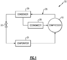
- An application contemplated here is a refrigerant system 32, such as represented in Figure 1 .
- Such a system 32 includes a compressor 10 in a cooling loop 35.
- the compressor 10 would be upstream of a condenser 29, expansion device 33, and evaporator 31, in turn.
- a portion of work fluid leaving the condenser 29 may return to the compressor 10 through an economizer 36.
- Refrigerant flows through the loop 35 to achieve a cooling output according to well-known processes.
- HVAC or refrigerant systems 32 of below 60 tons, or between 15 and 60 tons, are specifically contemplated herein. It should be understood that refrigerant systems 32 are only one example application for the compressors 10 disclosed below.
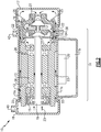
- Figure 2 illustrates a first embodiment of a centrifugal compressor 10 for systems with relatively low capacities.
- the capacity is below 60 tons. In a further embodiment, the capacity is between 15 tons and 60 tons.
- the compressor 10 of the present is hermetically sealed.
- the compressor 10 includes an exterior housing provided by a discharge end cap 17, a suction end cap 18, and a main housing 11.
- the main housing 11 is attached to the end caps 17, 18 by welds 22, thus rendering the compressor 10 hermetically sealed.
- the exterior housing is a three-piece housing and is provided exclusively by the end caps 17, 18, the main housing 11, and the welds 22.
- the welds 22 allow one to quickly and economically assemble exterior housing of the compressor 10, especially compared to some prior compressors, which are assembled using fasteners such as bolts or screws.
- the main housing 11 houses all working components of the compressor 10.
- the main housing 11 includes a drive module 12 having a motor stator 13, rotor 19, radial bearings 14a, 14b, and a thrust bearing 15.
- the drive module 12 is driven by a variable frequency drive.
- the main housing 11 also includes an aero module 16, which is an in-line impeller 27 arrangement in the embodiment depicted by Figure 2 .
- the aero module 16 compresses the working fluid 23 before the working fluid 23 exits the compressor 10 through a discharge port 42.
- the drive module 12 and aero module 16 are fastened to each other at a close fit point 24 by screws 25.
- the fixation of the drive module 12 and aero module 16 provides a simple design for the working parts of the compressor 10 that can simply slide into a tube portion 11a of the main housing 11, which increases the ease of assembly of the compressor 10.
- the fastening of the drive module 12 to the aero module 16 allows for modular design of the compressor 10.
- drive modules 12 and aero modules 16 can be designed separately. Separately designed drive modules 12 and aero modules 16 can be paired and fastened together to suit a given application.
- the radial bearings 14a, 14b and thrust bearing 15 are magnetic or gas bearings, as example, and enable oil free operation of the compressor 10.
- the working fluid 23 is used as a coolant for the drive module 12.
- the drive module 12 is cooled as the working fluid 23 flow through fluid paths 26 throughout the drive module 12. If the radial bearings 14a, 14b or thrust bearing 15 are gas bearings, the working fluid 23 is also used as a lubricant.
- the working fluid 23 flows from a suction port 40 to the aero module 16.
- the fluid paths 26 are dispersed throughout the drive module 12 such that the working fluid passes near each drive module 12 component. In particular, some fluid passes outside the stator 13, while some fluid passes around the shaft 19. The proximity of the fluid paths 26 to components of the drive module 12 allows the working fluid 23 to convectively cool the components of the drive module 12.
- Example working fluids include for such purposes include low global warming potential (GWP) refrigerants, like HFO refrigerants R1234ze, R1233zd, blend refrigerants R513a, R515a, and HFC refrigerant R 134a.
- GWP global warming potential
- the aero module 16 Downstream of the drive module 12, the working fluid 23 reaches the aero module 16.
- the aero module 16 has two impellers 27 arranged in a serial arrangement such that fluid exiting the outlet of the first impeller is directed to the inlet of the second impeller. It should be noted, however, that a dual-impeller arrangement is not required in all example. Other centrifugal compressor design variants come within the scope of the disclosure.
- the aero module 16 has a close back-to-back impeller 27 configuration.
- the working fluid 23 flows in series from a first impeller to a second impeller, and each impeller is mounted on the shaft 19 and facing the same direction.
- the close back-to-back impeller 27 arrangement of Figure 3 the working fluid 23 enters the aero module 16 from two different directions.
- the close back-to-back impellers 27 are mounted on the shaft 19 and face in opposite directions.
- the aero module 16 compresses the working fluid 23 in a known manner.
- the known manner of compression involves one or more impellers 27 rotationally accelerating the working fluid 23, then directing the accelerated working fluid 23 against stationary passages which bring the working fluid 23 to a state of relatively lesser velocity and relatively greater pressure.
- the compressed working fluid 23 exits the compressor 10 through a discharge port 42.
- the compressor 10 has electronics and a power module 20 contained in an integrated electronics compartment 11b.
- the electronics compartment 11b projects outwardly from the tube portion 11a.
- the electronics compartment 11b is contained within an enclosure formed by the tube portion 11a, discharge end cap 17, and suction end cap 18.
- the inclusion of the electronics compartment 11b within the enclosure of the compressor 10 further simplifies the compressor's 10 design.
- a seal 37 is used to isolate the electronics compartment 11b from the environment, but a cover 39 can be removed for service purposes.
- the impellers 27 are in a distant back-to-back configuration.
- the distant back-to-back impeller 27 arrangement has first and second aero modules 16a, 16b at opposite ends of the shaft 19. Both aero modules 16a, 16b enclose volutes 100 and one of the impellers 27.
- Gas from the first stage outlet port 42a arrives at the second stage inlet port 40b.
- the second stage inlet port 40b also receives gas from an economizer 36, which may be either in line or in parallel with the gas from the first stage outlet port 42a.
- the work fluid finally exits the compressor 10 at an intended degree of compression through second stage outlet port 42b.
- the two smaller aero modules 16a, 16b provide more design options for fitting around other components of the compressor 10 than the single aero module 16 of the above described embodiments.
- the distant back-to-back impeller 27 arrangement thus provides relative freedom in choosing diameters of the shaft 19 and impellers 27 compared to the embodiments described above.
- the compressor 10 of Figure 5 has a dedicated cooling circuit C for the drive module 12.
- the cooling circuit C diverts a portion of work fluid from a cooling loop, such as the loop 32 of Figure 1 , through a heat exchanger 132.
- the heat exchanger 132 is illustrated in Figure 5 as a passage wrapped in a coil around the drive module 12, but be constructed in a variety of other shapes or configurations.
- Figure 5 shows an example of the cooling circuit C return to the second stage impeller 27 inlet. In other words, the cooling circuit C return is as the same pressure of the second stage aero module 16b suction pressure.
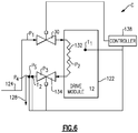
- FIG. 6 shows another example of a flow diagram for the cooling circuit C.
- the example cooling circuit C includes an expansion valve 30, a heat exchanger 132 downstream of the expansion valve 30, and a pressure regulator 134 downstream of the heat exchanger 132.
- the heat exchanger 132 is mounted around the drive module 12.
- the heat exchanger 132 may be a cold plate connected to a housing of the drive module 12.
- the expansion valve 30 and the pressure regulator 134 may be any type of device configured to regulate a flow of refrigerant, including mechanical valves, such as butterfly, gate or ball valves with electrical or pneumatic control (e.g., valves regulated by existing pressures).
- the control of the expansion valve 30 and pressure regulator 134 is regulated by a controller 138, which may be any known type of controller including memory, hardware, and software.
- the controller 138 is configured to store instructions, and to provide those instructions to the various components of the cooling circuit C, as will be discussed below.
- refrigerant enters the cooling circuit C from the condenser 129 through a diverted passage 124.
- the fluid is relatively high temperature, and in a liquid state.
- the cooling circuit C provides an appropriate amount of refrigerant to the drive module 12 without forming condensation in the drive module 12. Condensation of water (i.e., water droplets) may form within the drive module 12 if the temperature of the drive module 12 falls below a certain temperature. This condensation may cause damage to the various electrical components within the drive module 12.
- the pressure regulator 134 is controlled to control the pressure of refrigerant within the heat exchanger 132, which in turn controls the saturated temperature of that refrigerant, such that condensation does not form within the drive module 12.
- the expansion of refrigerant as it passes through the pressure regulator 134 is represented at P 3 in Figures 7 and 8 . Further, if an appropriate amount of refrigerant is provided to the heat exchanger 132 by the expansion valve 30, the refrigerant will absorb heat from the drive module 12 and be turned entirely into a vapor downstream of the heat exchanger 132, at point P 4 .
- the temperature of the drive module 12 is continually monitored by a first temperature sensor T 1 .
- the output of the first temperature sensor T 1 is reported to the controller 138.
- the controller 138 compares the output from the first temperature sensor T 1 to a target temperature T TARGET .
- the target temperature T TARGET is representative of a temperature at which there will be no (or extremely minimal) condensation within the drive module 12. That is, T TARGET is above a temperature at which condensation is known to begin to form.
- T TARGET is a predetermined value.
- the controller 138 is configured to determine T TARGET based on outside temperature and humidity.
- the controller 138 is further in communication with the pressure regulator 134, and is configured to command an adjustment of the pressure regulator 134 based on the output from the first temperature sensor T 1 .
- the position of the pressure regulator 134 controls the temperature of the refrigerant within the heat exchanger 132.
- the controller 138 maintains the position of the pressure regulator 134 such that the output from T 1 is equal to T TARGET .
- the controller 138 commands the pressure regulator 134 to incrementally close (e.g., by 5%).
- the controller 138 commands the pressure regulator 134 to incrementally open.
- Incrementally closing the pressure regulator 134 raises the temperature of the refrigerant within the heat exchanger 132, and prevents condensation from forming within the drive module 12.
- the controller 138 commands adjustment of the pressure regulator 34 until the output from T 1 returns to T TARGET .
- Closing the pressure regulator 134 raises the output from T 1 and raises the pressure P 2 , as illustrated graphically in Figure 7 at T 1 , and P 2 ,.
- the controller 138 Concurrent with the control of the pressure regulator 134, the controller 138 also controls the expansion valve 30 during operation.
- the temperature and pressure of the refrigerant within the cooling circuit C downstream of the heat exchanger 132 are determined by a second temperature sensor T 2 and a pressure sensor P S .
- the temperature sensor T 2 and the pressure sensor P S are located downstream of the pressure regulator 134.
- T 2 and P S could be located downstream of the heat exchanger 132 and upstream of the pressure regulator 134.
- the outputs from the second temperature sensor T 2 and the pressure sensor P S are reported to the controller 138.
- the controller 138 is configured to determine (e.g., by using a look-up table) a level of superheat within the refrigerant downstream of the heat exchanger (e.g., at P 4 ).
- the controller 138 then compares the level of superheat within the refrigerant at P 4 and a superheat target value SH TARGET . This comparison indicates whether an appropriate level of fluid was provided to the heat exchanger 132 by the expansion valve 30.
- the output from the second temperature sensor T 2 is compared to a saturation temperature T SAT at the pressure sensor output from the pressure sensor P S . From this comparison, the controller 138 determines the level of superheat in the refrigerant. In one example, the controller 138 maintains the position of the expansion valve 30 such that the level of superheat exhibited by the refrigerant equals SH TARGET . If the level of superheat exhibited by the refrigerant falls below SH TARGET , the controller 138 will determine that too much fluid is provided to the heat exchanger 132 and will incrementally close the expansion valve 30. Conversely, the controller 138 will command the expansion valve 132 to incrementally open if the level of superheat exhibited by the refrigerant exceeds SH TARGET .
- sensor outputs are typically in the form of a change in some electrical signal (such as resistance or voltage), which is capable of being interpreted as a change in temperature or pressure, for example, by a controller (such as the controller 138).
- controller such as the controller 138.
- the disclosure extends to all types of temperature and pressure sensors.
- the expansion valve 30 and pressure regulator 134 could be in communication with separate controllers. Additionally, the cooling circuit C does not require a dedicated controller 138. The functions of the controller 138 described above could be performed by a controller having additional functions. Further, the example control logic discussed above is exemplary. For instance, whereas in some instances this disclosure references the term "equal" in the context of comparisons to T TARGET and SH TARGET , the term “equal” is only used for purposes of illustration. In practice, there may be an acceptable (although relatively minor) variation in values that would still constitute "equal” for purposes of the control logic of this disclosure.
- compressor housing 11a can be used as a heatsink for power components, like power semiconductors. Use of the compressor housing 11a as a heatsink further simplifies the structure and enhances reliability.
Landscapes
- Engineering & Computer Science (AREA)
- Mechanical Engineering (AREA)
- General Engineering & Computer Science (AREA)
- Physics & Mathematics (AREA)
- Thermal Sciences (AREA)
- Structures Of Non-Positive Displacement Pumps (AREA)
- Fluid Mechanics (AREA)
- Electromagnetism (AREA)
Abstract
Description
- Centrifugal compressors are known to provide certain benefits such as enhanced operating efficiency and economy of implementation, especially in oil free designs. However, centrifugal compressors are usually reserved for high capacity applications. The benefits of centrifugal compressors have not been realized in low capacity applications in part because centrifugal designs have been complicated (and expensive) to manufacture within smaller housings.
- There is a large market for compressors capable of operating at low capacities. For example, many light commercial applications like roof-top air-conditioning include compressors that operate at relatively low capacities. Centrifugal compressors are uncommon in light commercial applications.
- There is described, in some examples, compressors and methods for use in low capacity applications.
- There is described a compressor according to an exemplary aspect of the present disclosure that operates within a system having a cooling capacity below 60 tons. The compressor may include, among other things, a hermetically sealed housing and, for example, a drive module and aero module within the housing. The drive module may include a motor, a rotor, and oil free bearings. The aero module may have a centrifugal impeller driven by the drive module to compress a working fluid. The compressor may be arranged such that a flow path for the working fluid flows through the drive module before reaching the aero module.
- In a further non-limiting embodiment of the foregoing compressor, the oil free bearings may be magnetic bearings.
- In a further non-limiting embodiment of the foregoing compressor, the oil free bearings may be gas bearings configured to use a working fluid as lubricant.
- In a further non-limiting embodiment of the foregoing compressor, the drive module may be cooled by suction gas before the suction gas reaches the impeller inlet.
- In a further non-limiting embodiment of the foregoing compressor, the drive module may be driven by a variable frequency drive.
- In a further non-limiting embodiment of the foregoing compressor, the variable frequency drive may drive the drive module to achieve system cooling capacities of between 15 and 60 tons.
- In a further non-limiting embodiment of the foregoing compressor, the sealed housing may act as a heatsink for power components of the variable frequency drive, and the working fluid cools the sealed housing.
- In a further non-limiting embodiment of the foregoing compressor, electronics may be enclosed in an integrated electronics housing that is part of the hermetically sealed housing.
- In a further non-limiting embodiment of the foregoing compressor, the integrated electronics housing may be within an exterior housing defined by two end caps and a tube portion of the sealed housing.
In a further non-limiting embodiment of the foregoing compressor, the compressor may comprise a further aero module within the housing, located about an opposite end of the rotor from the aero module. The aero modules may have a centrifugal impeller (27) driven by the drive module (12) to compress a working fluid (23). The compressor may be arranged such that a flow path for working fluid flows through the further aero module and then flows through the aero module. - There is also described a method of manufacturing a centrifugal compressor according to an exemplary aspect of the disclosure. The method may comprise disposing a drive module and aero module in a tube, and welding an end cap to one end of the tube to create a hermetically sealed housing.
- In a further non-limiting embodiment of the foregoing method, end caps may be welded to opposite ends of the tube to create a hermetically sealed housing.
- In a further non-limiting embodiment of the foregoing method, the method may further include fastening the aero module to the drive module.
- A compressor according to an exemplary aspect of the present disclosure may include, among other things, a drive module within a housing, and first and second aero modules located within the housing and about opposite ends of the rotor. The drive module may include a motor, a rotor, and bearings. The first and second aero modules may each have a centrifugal impeller driven by the drive module to compress a working fluid. The compressor may be arranged such that a flow path for working fluid flows through the first aero module. The working fluid may then flow through the second aero module.
- In a further non-limiting embodiment of the foregoing compressor, the compressor may be installed in a system having a cooling capacity of less than 60 tons.
- In a further non-limiting embodiment of the foregoing compressor, the housing may be hermetically sealed housing.
- In a further non-limiting embodiment of the foregoing compressor, the bearings may be oil free bearings.
- In a further non-limiting embodiment of the foregoing compressor, the compressor may include a dedicated cooling circuit for cooling the drive module using a heat exchanger and a diverted portion of the working fluid that flows through the heat exchanger.
- In a further non-limiting embodiment of the foregoing compressor, the heat exchanger may include a fluid passage coiled around the drive module.
- In a further non-limiting embodiment of the foregoing compressor, the dedicated cooling circuit may include a temperature sensor mounted to the drive module, and a controller. The temperature sensor may be configured to produce an output indicative of a temperature of the drive module. The controller may be configured to receive an output from the temperature sensor, and to command an adjustment of a pressure regulator based on the output from the temperature sensor.
- In a further non-limiting embodiment of the foregoing compressor, a flow path for the working fluid may exit the compressor after flowing through the first aero module but before flowing through the second aero module.
-
-
Figure 1 is a schematic illustration of a refrigerant loop. -
Figure 2 is an illustration of a centrifugal compressor according to one embodiment. -
Figure 3 is an illustration of a centrifugal compressor according to another embodiment. -
Figure 4 is an illustration of a centrifugal compressor according to a third embodiment. -
Figure 5 is an illustration of a centrifugal compressor according to a fourth embodiment. -
Figure 6 is a schematic illustration of a dedicated cooling circuit. -
Figure 7 is a plot of temperature versus entropy relative to the cooling circuit ofFigure 6 . -
Figure 8 is a plot of pressure versus enthalpy relative to the cooling circuit ofFigure 6 . - The
compressors 10 discussed herein are suitable for a wide range of applications. An application contemplated here is arefrigerant system 32, such as represented inFigure 1 . Such asystem 32 includes acompressor 10 in acooling loop 35. Thecompressor 10 would be upstream of acondenser 29,expansion device 33, andevaporator 31, in turn. A portion of work fluid leaving thecondenser 29 may return to thecompressor 10 through aneconomizer 36. Refrigerant flows through theloop 35 to achieve a cooling output according to well-known processes. HVAC orrefrigerant systems 32 of below 60 tons, or between 15 and 60 tons, are specifically contemplated herein. It should be understood thatrefrigerant systems 32 are only one example application for thecompressors 10 disclosed below. -
Figure 2 illustrates a first embodiment of acentrifugal compressor 10 for systems with relatively low capacities. In one example, the capacity is below 60 tons. In a further embodiment, the capacity is between 15 tons and 60 tons. - The
compressor 10 of the present is hermetically sealed. Thecompressor 10 includes an exterior housing provided by adischarge end cap 17, asuction end cap 18, and amain housing 11. Themain housing 11 is attached to the end caps 17, 18 bywelds 22, thus rendering thecompressor 10 hermetically sealed. In this example, the exterior housing is a three-piece housing and is provided exclusively by the end caps 17, 18, themain housing 11, and thewelds 22. - The
welds 22 allow one to quickly and economically assemble exterior housing of thecompressor 10, especially compared to some prior compressors, which are assembled using fasteners such as bolts or screws. - In this example, the
main housing 11 houses all working components of thecompressor 10. For example, themain housing 11 includes adrive module 12 having amotor stator 13,rotor 19, radial bearings 14a, 14b, and athrust bearing 15. In one embodiment, thedrive module 12 is driven by a variable frequency drive. - The
main housing 11 also includes anaero module 16, which is an in-line impeller 27 arrangement in the embodiment depicted byFigure 2 . Theaero module 16 compresses the workingfluid 23 before the workingfluid 23 exits thecompressor 10 through adischarge port 42. Thedrive module 12 andaero module 16 are fastened to each other at a closefit point 24 byscrews 25. The fixation of thedrive module 12 andaero module 16 provides a simple design for the working parts of thecompressor 10 that can simply slide into atube portion 11a of themain housing 11, which increases the ease of assembly of thecompressor 10. The fastening of thedrive module 12 to theaero module 16 allows for modular design of thecompressor 10. For example, drivemodules 12 andaero modules 16 can be designed separately. Separately designeddrive modules 12 andaero modules 16 can be paired and fastened together to suit a given application. - The radial bearings 14a, 14b and thrust
bearing 15 are magnetic or gas bearings, as example, and enable oil free operation of thecompressor 10. The workingfluid 23 is used as a coolant for thedrive module 12. Thedrive module 12 is cooled as the workingfluid 23 flow throughfluid paths 26 throughout thedrive module 12. If the radial bearings 14a, 14b or thrustbearing 15 are gas bearings, the workingfluid 23 is also used as a lubricant. - In one example, the working
fluid 23 flows from asuction port 40 to theaero module 16. Between thesuction port 40 and theaero module 16, thefluid paths 26 are dispersed throughout thedrive module 12 such that the working fluid passes near eachdrive module 12 component. In particular, some fluid passes outside thestator 13, while some fluid passes around theshaft 19. The proximity of thefluid paths 26 to components of thedrive module 12 allows the workingfluid 23 to convectively cool the components of thedrive module 12. - Since only one fluid is used as the working
fluid 23, coolant, and lubricant, separate distribution networks for each of the workingfluid 23, and coolant, are not necessary. A single distribution network carrying workingfluid 23, and coolant, further contributes to a compact and simple design. Example working fluids include for such purposes include low global warming potential (GWP) refrigerants, like HFO refrigerants R1234ze, R1233zd, blend refrigerants R513a, R515a, and HFC refrigerant R 134a. - Downstream of the
drive module 12, the workingfluid 23 reaches theaero module 16. In this example, theaero module 16 has twoimpellers 27 arranged in a serial arrangement such that fluid exiting the outlet of the first impeller is directed to the inlet of the second impeller. It should be noted, however, that a dual-impeller arrangement is not required in all example. Other centrifugal compressor design variants come within the scope of the disclosure. - For example, in another embodiment, which is shown in
Figure 3 , theaero module 16 has a close back-to-back impeller 27 configuration. In the in-line impeller 27 arrangement ofFigure 2 , the workingfluid 23 flows in series from a first impeller to a second impeller, and each impeller is mounted on theshaft 19 and facing the same direction. In the close back-to-back impeller 27 arrangement ofFigure 3 , the workingfluid 23 enters theaero module 16 from two different directions. The close back-to-back impellers 27 are mounted on theshaft 19 and face in opposite directions. With the close back-to-back configuration, the thrust force from theaero module 16 will be balanced, thus reducing thrust load on thedrive module 12. - With two stage compression, an extra flow can be introduced through the
economizer port 38 to the second stage inlet to improve the total compressor efficiency. - In either illustrated embodiment, the
aero module 16 compresses the workingfluid 23 in a known manner. In the case of centrifugal impellers, the known manner of compression involves one ormore impellers 27 rotationally accelerating the workingfluid 23, then directing the accelerated workingfluid 23 against stationary passages which bring the workingfluid 23 to a state of relatively lesser velocity and relatively greater pressure. The compressed workingfluid 23 exits thecompressor 10 through adischarge port 42. - Referring jointly to
Figures 2 and3 , thecompressor 10 has electronics and apower module 20 contained in anintegrated electronics compartment 11b. In this example, theelectronics compartment 11b projects outwardly from thetube portion 11a. - In a third embodiment illustrated in
Figure 4 , theelectronics compartment 11b is contained within an enclosure formed by thetube portion 11a, dischargeend cap 17, andsuction end cap 18. The inclusion of theelectronics compartment 11b within the enclosure of thecompressor 10 further simplifies the compressor's 10 design. Aseal 37 is used to isolate theelectronics compartment 11b from the environment, but acover 39 can be removed for service purposes. - In a fourth embodiment illustrated in
Figure 5 , theimpellers 27 are in a distant back-to-back configuration. The distant back-to-back impeller 27 arrangement has first and secondaero modules shaft 19. Bothaero modules volutes 100 and one of theimpellers 27. Gas enters thecompressor 10 at a firststage inlet port 40a, passes through aninlet valve 104, and exits a firststage outlet port 42a after passing through the firstaero module 16a. Gas from the firststage outlet port 42a arrives at the secondstage inlet port 40b. The secondstage inlet port 40b also receives gas from aneconomizer 36, which may be either in line or in parallel with the gas from the firststage outlet port 42a. The work fluid finally exits thecompressor 10 at an intended degree of compression through secondstage outlet port 42b. - The two smaller
aero modules compressor 10 than the singleaero module 16 of the above described embodiments. The distant back-to-back impeller 27 arrangement thus provides relative freedom in choosing diameters of theshaft 19 andimpellers 27 compared to the embodiments described above. - The
compressor 10 ofFigure 5 has a dedicated cooling circuit C for thedrive module 12. The cooling circuit C diverts a portion of work fluid from a cooling loop, such as theloop 32 ofFigure 1 , through aheat exchanger 132. Theheat exchanger 132 is illustrated inFigure 5 as a passage wrapped in a coil around thedrive module 12, but be constructed in a variety of other shapes or configurations.Figure 5 shows an example of the cooling circuit C return to thesecond stage impeller 27 inlet. In other words, the cooling circuit C return is as the same pressure of the second stageaero module 16b suction pressure. -
Figure 6 shows another example of a flow diagram for the cooling circuit C. The example cooling circuit C includes anexpansion valve 30, aheat exchanger 132 downstream of theexpansion valve 30, and apressure regulator 134 downstream of theheat exchanger 132. In this example, theheat exchanger 132 is mounted around thedrive module 12. In one example, theheat exchanger 132 may be a cold plate connected to a housing of thedrive module 12. - The
expansion valve 30 and thepressure regulator 134 may be any type of device configured to regulate a flow of refrigerant, including mechanical valves, such as butterfly, gate or ball valves with electrical or pneumatic control (e.g., valves regulated by existing pressures). In the illustrated example, the control of theexpansion valve 30 andpressure regulator 134 is regulated by acontroller 138, which may be any known type of controller including memory, hardware, and software. Thecontroller 138 is configured to store instructions, and to provide those instructions to the various components of the cooling circuit C, as will be discussed below. - During operation of the
refrigerant loop 32, in one example, refrigerant enters the cooling circuit C from the condenser 129 through a divertedpassage 124. At P1, the fluid is relatively high temperature, and in a liquid state. As fluid flows through theexpansion valve 30, it becomes a mixture of vapor and liquid, at P2. - The cooling circuit C provides an appropriate amount of refrigerant to the
drive module 12 without forming condensation in thedrive module 12. Condensation of water (i.e., water droplets) may form within thedrive module 12 if the temperature of thedrive module 12 falls below a certain temperature. This condensation may cause damage to the various electrical components within thedrive module 12. Thepressure regulator 134 is controlled to control the pressure of refrigerant within theheat exchanger 132, which in turn controls the saturated temperature of that refrigerant, such that condensation does not form within thedrive module 12. The expansion of refrigerant as it passes through thepressure regulator 134 is represented at P3 inFigures 7 and8 . Further, if an appropriate amount of refrigerant is provided to theheat exchanger 132 by theexpansion valve 30, the refrigerant will absorb heat from thedrive module 12 and be turned entirely into a vapor downstream of theheat exchanger 132, at point P4. - During operation of the
refrigerant loop 32, the temperature of thedrive module 12 is continually monitored by a first temperature sensor T1. In one example of this disclosure, the output of the first temperature sensor T1 is reported to thecontroller 138. Thecontroller 138 compares the output from the first temperature sensor T1 to a target temperature TTARGET. The target temperature TTARGET is representative of a temperature at which there will be no (or extremely minimal) condensation within thedrive module 12. That is, TTARGET is above a temperature at which condensation is known to begin to form. In one example TTARGET is a predetermined value. In other examples, thecontroller 138 is configured to determine TTARGET based on outside temperature and humidity. - The
controller 138 is further in communication with thepressure regulator 134, and is configured to command an adjustment of thepressure regulator 134 based on the output from the first temperature sensor T1. The position of thepressure regulator 134 controls the temperature of the refrigerant within theheat exchanger 132. In general, during normal operation of theloop 32, thecontroller 138 maintains the position of thepressure regulator 134 such that the output from T1 is equal to TTARGET. However, if the output from T1 decreases and falls below TTARGET, thecontroller 138 commands thepressure regulator 134 to incrementally close (e.g., by 5%). Conversely, if the output from T1 increases, thecontroller 138 commands thepressure regulator 134 to incrementally open. - Incrementally closing the
pressure regulator 134 raises the temperature of the refrigerant within theheat exchanger 132, and prevents condensation from forming within thedrive module 12. In one example, thecontroller 138 commands adjustment of the pressure regulator 34 until the output from T1 returns to TTARGET. Closing thepressure regulator 134 raises the output from T1 and raises the pressure P2, as illustrated graphically inFigure 7 at T1, and P2,. - Concurrent with the control of the
pressure regulator 134, thecontroller 138 also controls theexpansion valve 30 during operation. In this example the temperature and pressure of the refrigerant within the cooling circuit C downstream of theheat exchanger 132 are determined by a second temperature sensor T2 and a pressure sensor PS. In one example, the temperature sensor T2 and the pressure sensor PS are located downstream of thepressure regulator 134. However, T2 and PS could be located downstream of theheat exchanger 132 and upstream of thepressure regulator 134. - The outputs from the second temperature sensor T2 and the pressure sensor PS are reported to the
controller 138. Thecontroller 138 is configured to determine (e.g., by using a look-up table) a level of superheat within the refrigerant downstream of the heat exchanger (e.g., at P4). Thecontroller 138 then compares the level of superheat within the refrigerant at P4 and a superheat target value SHTARGET. This comparison indicates whether an appropriate level of fluid was provided to theheat exchanger 132 by theexpansion valve 30. - For example, the output from the second temperature sensor T2 is compared to a saturation temperature TSAT at the pressure sensor output from the pressure sensor PS. From this comparison, the
controller 138 determines the level of superheat in the refrigerant. In one example, thecontroller 138 maintains the position of theexpansion valve 30 such that the level of superheat exhibited by the refrigerant equals SHTARGET. If the level of superheat exhibited by the refrigerant falls below SHTARGET, thecontroller 138 will determine that too much fluid is provided to theheat exchanger 132 and will incrementally close theexpansion valve 30. Conversely, thecontroller 138 will command theexpansion valve 132 to incrementally open if the level of superheat exhibited by the refrigerant exceeds SHTARGET. - This disclosure references an "output" from a sensor in several instances. As is known in the art, sensor outputs are typically in the form of a change in some electrical signal (such as resistance or voltage), which is capable of being interpreted as a change in temperature or pressure, for example, by a controller (such as the controller 138). The disclosure extends to all types of temperature and pressure sensors.
- Further, while a
single controller 138 is illustrated, theexpansion valve 30 andpressure regulator 134 could be in communication with separate controllers. Additionally, the cooling circuit C does not require adedicated controller 138. The functions of thecontroller 138 described above could be performed by a controller having additional functions. Further, the example control logic discussed above is exemplary. For instance, whereas in some instances this disclosure references the term "equal" in the context of comparisons to TTARGET and SHTARGET, the term "equal" is only used for purposes of illustration. In practice, there may be an acceptable (although relatively minor) variation in values that would still constitute "equal" for purposes of the control logic of this disclosure. - The embodiments discussed above are simple enough to make oil free, centrifugal compressors economical for applications below 60 tons. Other known improvements of compressors, such as
economizers 36 or variable speed drives, may be incorporated into the disclosedcompressors 10 without causing the design to become prohibitively expensive to manufacture. It is to be noted thatcompressor housing 11a can be used as a heatsink for power components, like power semiconductors. Use of thecompressor housing 11a as a heatsink further simplifies the structure and enhances reliability. - Although the different examples have the specific components shown in the illustrations, embodiments of this disclosure are not limited to those particular combinations. It is possible to use some of the components or features from one of the examples in combination with features or components from another one of the examples.
- One of ordinary skill in this art would understand that the above-described embodiments are exemplary and non-limiting. That is, modifications of this disclosure would come within the scope of the claims. Accordingly, the following claims should be studied to determine their true scope and content.
Claims (15)
- A centrifugal compressor (10) within a system having a cooling capacity below 60 tons, comprising:a hermetically sealed housing (11);a drive module (12) within the housing (11), the drive module (12) including a motor (13), a rotor (19), and oil free bearings (14a, 14b, 15); andan aero module (16) within the housing (11), the aero module (16) having a centrifugal impeller (27) driven by the drive module (12) to compress a working fluid (23), wherein the compressor (10) is arranged such that a flow path for working fluid (23) flows through the drive module (12) before reaching the aero module (16).
- The centrifugal compressor of claim 1, wherein the oil free bearings (14a, 14b, 15) are magnetic bearings, or wherein the oil free bearings (14a, 14b, 15) are gas bearings configured to use working fluid as lubricant.
- The centrifugal compressor of any preceding claim, wherein the drive module (12) is cooled by suction gas before the suction gas reaches the impeller inlet (27).
- The centrifugal compressor of any preceding claim, wherein the drive module (12) is driven by a variable frequency drive, and optionally wherein the variable frequency drive can drive the drive module (12) to achieve system cooling capacities of between 15 and 60 tons.
- The centrifugal compressor of claim 5, wherein the sealed housing (11) acts as a heatsink for power components of the variable frequency drive, and the working fluid (23) cools the sealed housing (11).
- The centrifugal compressor of any preceding claim, further comprising electronics (20) enclosed in an integrated electronics housing (11b) that is part of the hermetically sealed housing (11).
- The centrifugal compressor of claim 8, wherein the integrated electronics housing (11b) is within an exterior housing defined by two end caps (17, 18) and a tube portion (11a) of the sealed housing (11).
- The centrifugal compressor of any preceding claim, further comprising a further aero module (16a) within the housing, located about an opposite end of the rotor (19) from the aero module (16b), the aero modules (16a, 16b) each having a centrifugal impeller (27) driven by the drive module (12) to compress a working fluid (23), wherein the compressor is arranged such that a flow path for working fluid flows (23) through the further aero module (16a) and then flows through the aero module (16b).
- A method of manufacturing a centrifugal compressor (10) comprising:disposing a drive module (12) and aero module (16) in a tube (11a); andwelding end caps (17, 18) to opposite ends of the tube (11a) to create a hermetically sealed housing (11).
- The method of claim 9, further comprising:fastening the aero module (16) to the drive module (16).
- A centrifugal compressor (10), comprising:a drive module (16) within a housing (11), the drive module (16) including a motor (13), a rotor (19), and bearings (14a, 14b, 15); andfirst and second aero modules (16a, 16b) within the housing (11) and located about opposite ends of the rotor (19), the first and second aero modules (16a, 16b) each having a centrifugal impeller (27) driven by the drive module (12) to compress a working fluid (23), wherein the compressor is arranged such that a flow path for working fluid flows (23) through the first aero module (16a) and then flows through the second aero module (16b).
- The centrifugal compressor of claim 11, within a system having a cooling capacity of below 60 tons.
- The centrifugal compressor of claim 11 or 12, wherein at least one of:the housing (11) is hermetically sealed housing; andthe bearings (14a, 14b, 15) are oil free bearings; anda flowpath (42a) for the working fluid exits the compressor (10) after flowing through the first aero module (16a) and before flowing through the second aero module (16b).
- The centrifugal compressor of any of claims 11 to 13, comprising a dedicated cooling circuit (C) for cooling the drive module (12) using a heat exchanger (132) and a diverted portion of the working fluid (124) that flows through the heat exchanger, optionally wherein the heat exchanger is a fluid passage coiled around the drive module (12)..
- The centrifugal compressor of claim 14, further comprising:a temperature sensor (T1) mounted to the drive module (12), the temperature sensor (T1) configured to produce an output indicative of a temperature of the drive module (12); anda controller (138) configured to receive an output from the temperature sensor (T1), and to command an adjustment of a pressure regulator (134) based on the output from the temperature sensor (T1).
Applications Claiming Priority (1)
| Application Number | Priority Date | Filing Date | Title |
|---|---|---|---|
| US201762458761P | 2017-02-14 | 2017-02-14 |
Publications (2)
| Publication Number | Publication Date |
|---|---|
| EP3361104A1 true EP3361104A1 (en) | 2018-08-15 |
| EP3361104B1 EP3361104B1 (en) | 2022-03-30 |
Family
ID=61223788
Family Applications (1)
| Application Number | Title | Priority Date | Filing Date |
|---|---|---|---|
| EP18156631.6A Active EP3361104B1 (en) | 2017-02-14 | 2018-02-14 | Oil free centrifugal compressor for use in low capacity applications |
Country Status (3)
| Country | Link |
|---|---|
| US (1) | US11274679B2 (en) |
| EP (1) | EP3361104B1 (en) |
| CN (1) | CN108425862B (en) |
Cited By (5)
| Publication number | Priority date | Publication date | Assignee | Title |
|---|---|---|---|---|
| EP3745050A1 (en) * | 2019-05-31 | 2020-12-02 | Trane International Inc. | Heat transfer circuit with increased bearing lubricant temperature, and method of supplying thereof |
| WO2021050662A1 (en) * | 2019-09-12 | 2021-03-18 | Carrier Corporation | Centrifugal compressor and refrigerating device |
| US20220106967A1 (en) * | 2018-06-25 | 2022-04-07 | Cluster Lng Co., Ltd. | Combustible gas compressor |
| EP4446585A4 (en) * | 2022-03-14 | 2025-12-10 | Ihi Corp | REFRIGERANT COMPRESSOR |
| US12546323B2 (en) | 2022-03-16 | 2026-02-10 | Ihi Corporation | Compressor with curved passage |
Families Citing this family (29)
| Publication number | Priority date | Publication date | Assignee | Title |
|---|---|---|---|---|
| JP6668161B2 (en) * | 2016-05-11 | 2020-03-18 | 株式会社マーレ フィルターシステムズ | Turbocharger |
| EP3396297A1 (en) * | 2017-04-28 | 2018-10-31 | Siemens Aktiengesellschaft | Cooling device |
| US11927193B2 (en) * | 2017-11-14 | 2024-03-12 | Garrett Transportation I Inc | Multi-stage compressor with turbine section for fuel cell system |
| FR3086707B1 (en) * | 2018-10-01 | 2021-02-12 | Danfoss As | A REFRIGERATION SYSTEM INCLUDING A BYPASS FLOW DUCT TO COOL A COMPRESSOR MOTOR |
| CN109210011A (en) * | 2018-10-20 | 2019-01-15 | 广东艾高装备科技有限公司 | A kind of low noise magnetic levitation centrifugal air compressor |
| CN111365254B (en) * | 2018-12-25 | 2025-03-07 | 珠海格力电器股份有限公司 | Compressors for optimizing interior space |
| CN111486104A (en) * | 2019-01-29 | 2020-08-04 | 青岛海尔智能技术研发有限公司 | Centrifugal compressor and heat pump system |
| CN111486102B (en) * | 2019-01-29 | 2022-06-14 | 青岛海尔智能技术研发有限公司 | Centrifugal compressor and heat pump system |
| WO2020251723A1 (en) * | 2019-06-12 | 2020-12-17 | Carrier Corporation | Two stage refrigeration cycle having single gas cooler |
| JP2021055613A (en) * | 2019-09-30 | 2021-04-08 | ダイキン工業株式会社 | Turbo compressor |
| US11635091B2 (en) * | 2020-03-13 | 2023-04-25 | Honeywell International Inc. | Compressor with integrated accumulator |
| US11841031B2 (en) * | 2020-03-13 | 2023-12-12 | Honeywell International Inc. | Compressor sensor mount |
| US20210285691A1 (en) * | 2020-03-13 | 2021-09-16 | Honeywell International Inc. | Sealable vapor cooled compressor housing with adapter |
| CN113922564A (en) * | 2020-07-08 | 2022-01-11 | 上海海立电器有限公司 | Refrigeration cycle system and method |
| CN114370411A (en) * | 2020-10-15 | 2022-04-19 | 海德韦尔(太仓)能源科技有限公司 | Air Compression Device, Multistage Air Compression Device and Hydrogen Fuel Cell |
| FR3122708A1 (en) * | 2021-05-06 | 2022-11-11 | IFP Energies Nouvelles | Electrified Gas Compressor with Dual Compression Stage |
| KR102884185B1 (en) * | 2021-05-07 | 2025-11-13 | 한온시스템 주식회사 | Multi stage refrigerant compressor |
| CN115370591B (en) * | 2021-05-19 | 2026-04-24 | 南京集智动力科技有限公司 | Boosting suction cooling type air flotation centrifugal air compressor and its working method |
| CN115493306A (en) | 2021-06-17 | 2022-12-20 | 开利公司 | Refrigeration system and oil return method therefor |
| KR102627489B1 (en) * | 2021-08-16 | 2024-01-23 | 터보윈 주식회사 | Gas compressor with cooling system using pressure difference of gas |
| JP7460705B2 (en) * | 2022-08-05 | 2024-04-02 | 三菱重工サーマルシステムズ株式会社 | Turbo compressor and turbo chiller equipped with the same |
| KR102703052B1 (en) * | 2022-10-25 | 2024-09-04 | ㈜티앤이코리아 | Turbo compressor capable of cooling the power converter of the motor |
| CN116591975A (en) * | 2023-06-02 | 2023-08-15 | 势加透博洁净动力如皋有限公司 | Air-cooled air compressor |
| CN121605245A (en) * | 2023-08-01 | 2026-03-03 | 谷轮有限合伙公司 | Method and system for controlling a compressor cooling system |
| US12698927B2 (en) | 2023-08-01 | 2026-08-04 | Copeland Lp | Methods and systems for controlling a compressor cooling system |
| JP2025088441A (en) * | 2023-11-30 | 2025-06-11 | 株式会社豊田自動織機 | Centrifugal Compressor |
| JP2025118247A (en) * | 2024-01-31 | 2025-08-13 | 株式会社荏原製作所 | Magnetic bearing device and compressor |
| US12497965B2 (en) * | 2024-03-06 | 2025-12-16 | Garrett Transportation I Inc. | Refrigerant cooled electric motor |
| WO2025212238A1 (en) * | 2024-04-05 | 2025-10-09 | Danfoss A/S | Economizer flow and inlet guide vane configurations for refrigerant compressor |
Citations (5)
| Publication number | Priority date | Publication date | Assignee | Title |
|---|---|---|---|---|
| JP2000240596A (en) * | 1998-12-25 | 2000-09-05 | Daikin Ind Ltd | Turbo compressor |
| US6155802A (en) * | 1997-11-29 | 2000-12-05 | Lg Electronics, Inc. | Turbo compressor |
| US20050223737A1 (en) * | 2002-02-28 | 2005-10-13 | Turbocor, Inc. | Centrifugal compressor |
| US20120128512A1 (en) * | 2009-08-03 | 2012-05-24 | Atlas Copco Airpower | Turbocompressor system |
| WO2016003467A1 (en) * | 2014-07-03 | 2016-01-07 | Danfoss A/S | Refrigerant cooling for variable speed drive |
Family Cites Families (28)
| Publication number | Priority date | Publication date | Assignee | Title |
|---|---|---|---|---|
| US3975117A (en) * | 1974-09-27 | 1976-08-17 | James Coolidge Carter | Pump and motor unit with inducer at one end and centrifugal impeller at opposite end of the motor |
| US4032312A (en) | 1976-04-16 | 1977-06-28 | Carrier Corporation | Centrifugal compressor |
| US5350039A (en) | 1993-02-25 | 1994-09-27 | Nartron Corporation | Low capacity centrifugal refrigeration compressor |
| US5888053A (en) * | 1995-02-10 | 1999-03-30 | Ebara Corporation | Pump having first and second outer casing members |
| US5904471A (en) | 1996-12-20 | 1999-05-18 | Turbodyne Systems, Inc. | Cooling means for a motor-driven centrifugal air compressor |
| DE19904119C2 (en) | 1999-02-03 | 2002-06-27 | Draeger Medical Ag | Rotary compressor for ventilation systems |
| JP2000240598A (en) | 1999-02-18 | 2000-09-05 | Chofu Seisakusho Co Ltd | Drainage mechanism of circulation pump and equipment using it |
| EP1074746B1 (en) | 1999-07-16 | 2005-05-18 | Man Turbo Ag | Turbo compressor |
| KR100356506B1 (en) | 2000-09-27 | 2002-10-18 | 엘지전자 주식회사 | Turbo compressor |
| IL140407A0 (en) | 2000-12-19 | 2002-02-10 | Turbosystem Ltd | Integrated turbocompressor |
| US6632077B2 (en) | 2002-01-11 | 2003-10-14 | Carrier Corporation | Hybrid bearing arrangement for centrifugal compressor |
| JP4300088B2 (en) * | 2003-09-29 | 2009-07-22 | 日機装株式会社 | Submerged pump |
| JP5063970B2 (en) * | 2006-10-02 | 2012-10-31 | 富士重工業株式会社 | Portable power work machine |
| US8156757B2 (en) | 2006-10-06 | 2012-04-17 | Aff-Mcquay Inc. | High capacity chiller compressor |
| US20080135635A1 (en) | 2006-12-08 | 2008-06-12 | The Hong Kong Polytechnic University | High-low speed control algorithm for direct expansion air-conditioning systems for improved indoor humidity control and energy efficiency |
| US7847454B2 (en) | 2007-03-08 | 2010-12-07 | General Electric Company | Encapsulated stator assembly and process for making |
| JP5209259B2 (en) | 2007-09-25 | 2013-06-12 | サンデン株式会社 | Drive circuit integrated electric compressor |
| DE102008038787A1 (en) * | 2008-08-13 | 2010-02-18 | Siemens Aktiengesellschaft | Fluid energy machine |
| US9726196B2 (en) | 2010-10-27 | 2017-08-08 | Dresser-Rand Company | System and cooling for rapid pressurization of a motor-bearing cooling loop for a hermetically sealed motor/compressor system |
| US9200643B2 (en) | 2010-10-27 | 2015-12-01 | Dresser-Rand Company | Method and system for cooling a motor-compressor with a closed-loop cooling circuit |
| EP2500577B1 (en) | 2011-03-12 | 2016-06-22 | Grundfos Management a/s | Heat circulation pump |
| WO2012145486A2 (en) | 2011-04-20 | 2012-10-26 | Dresser-Rand Company | Magnetic bearing system for heavy loaded compressor |
| GB2493975B (en) * | 2011-08-26 | 2015-02-11 | Dyson Technology Ltd | Turbomachine |
| DE102012016844A1 (en) * | 2011-08-30 | 2013-02-28 | Ksb Aktiengesellschaft | Turbo compressor and use |
| GB2514271B (en) * | 2011-12-06 | 2016-09-14 | Trane Int Inc | Rolling element bearings for an oil-free liquid chiller |
| JP6155573B2 (en) | 2012-08-28 | 2017-07-05 | 株式会社Ihi | Centrifugal compressor |
| US10267539B2 (en) * | 2014-02-17 | 2019-04-23 | Carrier Corporation | Hot gas bypass for two-stage compressor |
| CN205089651U (en) * | 2015-11-09 | 2016-03-16 | 成都成发科能动力工程有限公司 | It does not have oily centrifugal compressor group to become sled formula |
-
2018
- 2018-02-09 US US15/892,872 patent/US11274679B2/en active Active
- 2018-02-14 CN CN201810151079.6A patent/CN108425862B/en active Active
- 2018-02-14 EP EP18156631.6A patent/EP3361104B1/en active Active
Patent Citations (5)
| Publication number | Priority date | Publication date | Assignee | Title |
|---|---|---|---|---|
| US6155802A (en) * | 1997-11-29 | 2000-12-05 | Lg Electronics, Inc. | Turbo compressor |
| JP2000240596A (en) * | 1998-12-25 | 2000-09-05 | Daikin Ind Ltd | Turbo compressor |
| US20050223737A1 (en) * | 2002-02-28 | 2005-10-13 | Turbocor, Inc. | Centrifugal compressor |
| US20120128512A1 (en) * | 2009-08-03 | 2012-05-24 | Atlas Copco Airpower | Turbocompressor system |
| WO2016003467A1 (en) * | 2014-07-03 | 2016-01-07 | Danfoss A/S | Refrigerant cooling for variable speed drive |
Non-Patent Citations (1)
| Title |
|---|
| DAVID WILLIAMSON: "INTRODUCTION TO DANFOSS TURBOCOR COMPRESSORS", 14 April 2016 (2016-04-14), XP055484991, Retrieved from the Internet <URL:https://www.atic.be/images/3_DANFOSS_david_williamson.pdf> [retrieved on 20180615] * |
Cited By (8)
| Publication number | Priority date | Publication date | Assignee | Title |
|---|---|---|---|---|
| US20220106967A1 (en) * | 2018-06-25 | 2022-04-07 | Cluster Lng Co., Ltd. | Combustible gas compressor |
| US11815103B2 (en) * | 2018-06-25 | 2023-11-14 | Cluster Lng Co., Ltd. | Boil-off gas compressor for LNG fueled ship |
| US11892010B2 (en) * | 2018-06-25 | 2024-02-06 | Cluster Lng Co., Ltd. | Combustible gas compressor |
| EP3745050A1 (en) * | 2019-05-31 | 2020-12-02 | Trane International Inc. | Heat transfer circuit with increased bearing lubricant temperature, and method of supplying thereof |
| WO2021050662A1 (en) * | 2019-09-12 | 2021-03-18 | Carrier Corporation | Centrifugal compressor and refrigerating device |
| US11506210B2 (en) | 2019-09-12 | 2022-11-22 | Carrier Corporation | Centrifugal compressor and refrigerating device |
| EP4446585A4 (en) * | 2022-03-14 | 2025-12-10 | Ihi Corp | REFRIGERANT COMPRESSOR |
| US12546323B2 (en) | 2022-03-16 | 2026-02-10 | Ihi Corporation | Compressor with curved passage |
Also Published As
| Publication number | Publication date |
|---|---|
| US11274679B2 (en) | 2022-03-15 |
| CN108425862A (en) | 2018-08-21 |
| EP3361104B1 (en) | 2022-03-30 |
| CN108425862B (en) | 2022-04-12 |
| US20180231006A1 (en) | 2018-08-16 |
Similar Documents
| Publication | Publication Date | Title |
|---|---|---|
| US11274679B2 (en) | Oil free centrifugal compressor for use in low capacity applications | |
| US20220220976A1 (en) | Cooling system for centrifugal compressor and refrigeration system including same | |
| US6651451B2 (en) | Variable capacity refrigeration system with a single-frequency compressor | |
| EP2992275B1 (en) | System comprising first and second compressors | |
| US9360011B2 (en) | System including high-side and low-side compressors | |
| EP3377829B1 (en) | Climate-control system with compressor with cooling system and method of using the same | |
| EP2889551B1 (en) | Multi-evaporator trans-critical cooling systems | |
| EP4265983A1 (en) | Refrigeration system, control method thereof and transport vehicle | |
| CN113316699A (en) | Oil control for climate control system | |
| US10234175B2 (en) | Turbo refrigerator | |
| JP2007232230A (en) | Refrigeration equipment | |
| US20240318880A1 (en) | Compressor cooling systems and methods including coolant damping chamber | |
| US11885535B2 (en) | ETXV direct discharge injection compressor | |
| EP3957931B1 (en) | Refrigeration apparatus | |
| JP2011241790A (en) | Two-stage boost compressor | |
| US12000399B2 (en) | Volume ratio control system for a compressor | |
| JP2011236855A (en) | Two-stage boosting compressor | |
| EP4088031B1 (en) | Volume ratio control system for a compressor | |
| US20250137696A1 (en) | Compressor for refrigeration system including internal coolant return line | |
| JP2008281254A (en) | Refrigeration cycle apparatus and vehicle air conditioner | |
| KR20070101897A (en) | Air conditioner and its control method |
Legal Events
| Date | Code | Title | Description |
|---|---|---|---|
| PUAI | Public reference made under article 153(3) epc to a published international application that has entered the european phase |
Free format text: ORIGINAL CODE: 0009012 |
|
| STAA | Information on the status of an ep patent application or granted ep patent |
Free format text: STATUS: THE APPLICATION HAS BEEN PUBLISHED |
|
| AK | Designated contracting states |
Kind code of ref document: A1 Designated state(s): AL AT BE BG CH CY CZ DE DK EE ES FI FR GB GR HR HU IE IS IT LI LT LU LV MC MK MT NL NO PL PT RO RS SE SI SK SM TR |
|
| AX | Request for extension of the european patent |
Extension state: BA ME |
|
| STAA | Information on the status of an ep patent application or granted ep patent |
Free format text: STATUS: REQUEST FOR EXAMINATION WAS MADE |
|
| 17P | Request for examination filed |
Effective date: 20190213 |
|
| RBV | Designated contracting states (corrected) |
Designated state(s): AL AT BE BG CH CY CZ DE DK EE ES FI FR GB GR HR HU IE IS IT LI LT LU LV MC MK MT NL NO PL PT RO RS SE SI SK SM TR |
|
| STAA | Information on the status of an ep patent application or granted ep patent |
Free format text: STATUS: EXAMINATION IS IN PROGRESS |
|
| 17Q | First examination report despatched |
Effective date: 20191128 |
|
| REG | Reference to a national code |
Ref country code: DE Ref legal event code: R079 Ref document number: 602018032815 Country of ref document: DE Free format text: PREVIOUS MAIN CLASS: F04D0029580000 Ipc: F04D0017120000 |
|
| GRAP | Despatch of communication of intention to grant a patent |
Free format text: ORIGINAL CODE: EPIDOSNIGR1 |
|
| STAA | Information on the status of an ep patent application or granted ep patent |
Free format text: STATUS: GRANT OF PATENT IS INTENDED |
|
| INTG | Intention to grant announced |
Effective date: 20211210 |
|
| RIC1 | Information provided on ipc code assigned before grant |
Ipc: F25B 49/02 20060101ALI20211126BHEP Ipc: F25B 31/00 20060101ALI20211126BHEP Ipc: F04D 27/02 20060101ALI20211126BHEP Ipc: F04D 29/62 20060101ALI20211126BHEP Ipc: F04D 29/42 20060101ALI20211126BHEP Ipc: F04D 25/06 20060101ALI20211126BHEP Ipc: F04D 29/58 20060101ALI20211126BHEP Ipc: F04D 17/12 20060101AFI20211126BHEP |
|
| GRAS | Grant fee paid |
Free format text: ORIGINAL CODE: EPIDOSNIGR3 |
|
| GRAA | (expected) grant |
Free format text: ORIGINAL CODE: 0009210 |
|
| STAA | Information on the status of an ep patent application or granted ep patent |
Free format text: STATUS: THE PATENT HAS BEEN GRANTED |
|
| AK | Designated contracting states |
Kind code of ref document: B1 Designated state(s): AL AT BE BG CH CY CZ DE DK EE ES FI FR GB GR HR HU IE IS IT LI LT LU LV MC MK MT NL NO PL PT RO RS SE SI SK SM TR |
|
| REG | Reference to a national code |
Ref country code: GB Ref legal event code: FG4D |
|
| REG | Reference to a national code |
Ref country code: CH Ref legal event code: EP |
|
| REG | Reference to a national code |
Ref country code: AT Ref legal event code: REF Ref document number: 1479434 Country of ref document: AT Kind code of ref document: T Effective date: 20220415 |
|
| REG | Reference to a national code |
Ref country code: DE Ref legal event code: R096 Ref document number: 602018032815 Country of ref document: DE |
|
| REG | Reference to a national code |
Ref country code: IE Ref legal event code: FG4D |
|
| REG | Reference to a national code |
Ref country code: LT Ref legal event code: MG9D |
|
| PG25 | Lapsed in a contracting state [announced via postgrant information from national office to epo] |
Ref country code: SE Free format text: LAPSE BECAUSE OF FAILURE TO SUBMIT A TRANSLATION OF THE DESCRIPTION OR TO PAY THE FEE WITHIN THE PRESCRIBED TIME-LIMIT Effective date: 20220330 Ref country code: RS Free format text: LAPSE BECAUSE OF FAILURE TO SUBMIT A TRANSLATION OF THE DESCRIPTION OR TO PAY THE FEE WITHIN THE PRESCRIBED TIME-LIMIT Effective date: 20220330 Ref country code: NO Free format text: LAPSE BECAUSE OF FAILURE TO SUBMIT A TRANSLATION OF THE DESCRIPTION OR TO PAY THE FEE WITHIN THE PRESCRIBED TIME-LIMIT Effective date: 20220630 Ref country code: LT Free format text: LAPSE BECAUSE OF FAILURE TO SUBMIT A TRANSLATION OF THE DESCRIPTION OR TO PAY THE FEE WITHIN THE PRESCRIBED TIME-LIMIT Effective date: 20220330 Ref country code: HR Free format text: LAPSE BECAUSE OF FAILURE TO SUBMIT A TRANSLATION OF THE DESCRIPTION OR TO PAY THE FEE WITHIN THE PRESCRIBED TIME-LIMIT Effective date: 20220330 Ref country code: BG Free format text: LAPSE BECAUSE OF FAILURE TO SUBMIT A TRANSLATION OF THE DESCRIPTION OR TO PAY THE FEE WITHIN THE PRESCRIBED TIME-LIMIT Effective date: 20220630 |
|
| REG | Reference to a national code |
Ref country code: NL Ref legal event code: MP Effective date: 20220330 |
|
| REG | Reference to a national code |
Ref country code: AT Ref legal event code: MK05 Ref document number: 1479434 Country of ref document: AT Kind code of ref document: T Effective date: 20220330 |
|
| PG25 | Lapsed in a contracting state [announced via postgrant information from national office to epo] |
Ref country code: LV Free format text: LAPSE BECAUSE OF FAILURE TO SUBMIT A TRANSLATION OF THE DESCRIPTION OR TO PAY THE FEE WITHIN THE PRESCRIBED TIME-LIMIT Effective date: 20220330 Ref country code: GR Free format text: LAPSE BECAUSE OF FAILURE TO SUBMIT A TRANSLATION OF THE DESCRIPTION OR TO PAY THE FEE WITHIN THE PRESCRIBED TIME-LIMIT Effective date: 20220701 Ref country code: FI Free format text: LAPSE BECAUSE OF FAILURE TO SUBMIT A TRANSLATION OF THE DESCRIPTION OR TO PAY THE FEE WITHIN THE PRESCRIBED TIME-LIMIT Effective date: 20220330 |
|
| PG25 | Lapsed in a contracting state [announced via postgrant information from national office to epo] |
Ref country code: NL Free format text: LAPSE BECAUSE OF FAILURE TO SUBMIT A TRANSLATION OF THE DESCRIPTION OR TO PAY THE FEE WITHIN THE PRESCRIBED TIME-LIMIT Effective date: 20220330 |
|
| PG25 | Lapsed in a contracting state [announced via postgrant information from national office to epo] |
Ref country code: SM Free format text: LAPSE BECAUSE OF FAILURE TO SUBMIT A TRANSLATION OF THE DESCRIPTION OR TO PAY THE FEE WITHIN THE PRESCRIBED TIME-LIMIT Effective date: 20220330 Ref country code: SK Free format text: LAPSE BECAUSE OF FAILURE TO SUBMIT A TRANSLATION OF THE DESCRIPTION OR TO PAY THE FEE WITHIN THE PRESCRIBED TIME-LIMIT Effective date: 20220330 Ref country code: RO Free format text: LAPSE BECAUSE OF FAILURE TO SUBMIT A TRANSLATION OF THE DESCRIPTION OR TO PAY THE FEE WITHIN THE PRESCRIBED TIME-LIMIT Effective date: 20220330 Ref country code: PT Free format text: LAPSE BECAUSE OF FAILURE TO SUBMIT A TRANSLATION OF THE DESCRIPTION OR TO PAY THE FEE WITHIN THE PRESCRIBED TIME-LIMIT Effective date: 20220801 Ref country code: ES Free format text: LAPSE BECAUSE OF FAILURE TO SUBMIT A TRANSLATION OF THE DESCRIPTION OR TO PAY THE FEE WITHIN THE PRESCRIBED TIME-LIMIT Effective date: 20220330 Ref country code: EE Free format text: LAPSE BECAUSE OF FAILURE TO SUBMIT A TRANSLATION OF THE DESCRIPTION OR TO PAY THE FEE WITHIN THE PRESCRIBED TIME-LIMIT Effective date: 20220330 Ref country code: CZ Free format text: LAPSE BECAUSE OF FAILURE TO SUBMIT A TRANSLATION OF THE DESCRIPTION OR TO PAY THE FEE WITHIN THE PRESCRIBED TIME-LIMIT Effective date: 20220330 Ref country code: AT Free format text: LAPSE BECAUSE OF FAILURE TO SUBMIT A TRANSLATION OF THE DESCRIPTION OR TO PAY THE FEE WITHIN THE PRESCRIBED TIME-LIMIT Effective date: 20220330 |
|
| PG25 | Lapsed in a contracting state [announced via postgrant information from national office to epo] |
Ref country code: PL Free format text: LAPSE BECAUSE OF FAILURE TO SUBMIT A TRANSLATION OF THE DESCRIPTION OR TO PAY THE FEE WITHIN THE PRESCRIBED TIME-LIMIT Effective date: 20220330 Ref country code: IS Free format text: LAPSE BECAUSE OF FAILURE TO SUBMIT A TRANSLATION OF THE DESCRIPTION OR TO PAY THE FEE WITHIN THE PRESCRIBED TIME-LIMIT Effective date: 20220730 Ref country code: AL Free format text: LAPSE BECAUSE OF FAILURE TO SUBMIT A TRANSLATION OF THE DESCRIPTION OR TO PAY THE FEE WITHIN THE PRESCRIBED TIME-LIMIT Effective date: 20220330 |
|
| REG | Reference to a national code |
Ref country code: DE Ref legal event code: R097 Ref document number: 602018032815 Country of ref document: DE |
|
| PG25 | Lapsed in a contracting state [announced via postgrant information from national office to epo] |
Ref country code: DK Free format text: LAPSE BECAUSE OF FAILURE TO SUBMIT A TRANSLATION OF THE DESCRIPTION OR TO PAY THE FEE WITHIN THE PRESCRIBED TIME-LIMIT Effective date: 20220330 |
|
| PLBE | No opposition filed within time limit |
Free format text: ORIGINAL CODE: 0009261 |
|
| STAA | Information on the status of an ep patent application or granted ep patent |
Free format text: STATUS: NO OPPOSITION FILED WITHIN TIME LIMIT |
|
| 26N | No opposition filed |
Effective date: 20230103 |
|
| PG25 | Lapsed in a contracting state [announced via postgrant information from national office to epo] |
Ref country code: SI Free format text: LAPSE BECAUSE OF FAILURE TO SUBMIT A TRANSLATION OF THE DESCRIPTION OR TO PAY THE FEE WITHIN THE PRESCRIBED TIME-LIMIT Effective date: 20220330 |
|
| P01 | Opt-out of the competence of the unified patent court (upc) registered |
Effective date: 20230617 |
|
| PG25 | Lapsed in a contracting state [announced via postgrant information from national office to epo] |
Ref country code: IT Free format text: LAPSE BECAUSE OF FAILURE TO SUBMIT A TRANSLATION OF THE DESCRIPTION OR TO PAY THE FEE WITHIN THE PRESCRIBED TIME-LIMIT Effective date: 20220330 |
|
| PG25 | Lapsed in a contracting state [announced via postgrant information from national office to epo] |
Ref country code: MC Free format text: LAPSE BECAUSE OF FAILURE TO SUBMIT A TRANSLATION OF THE DESCRIPTION OR TO PAY THE FEE WITHIN THE PRESCRIBED TIME-LIMIT Effective date: 20220330 |
|
| REG | Reference to a national code |
Ref country code: CH Ref legal event code: PL |
|
| REG | Reference to a national code |
Ref country code: BE Ref legal event code: MM Effective date: 20230228 |
|
| PG25 | Lapsed in a contracting state [announced via postgrant information from national office to epo] |
Ref country code: LU Free format text: LAPSE BECAUSE OF NON-PAYMENT OF DUE FEES Effective date: 20230214 Ref country code: LI Free format text: LAPSE BECAUSE OF NON-PAYMENT OF DUE FEES Effective date: 20230228 Ref country code: CH Free format text: LAPSE BECAUSE OF NON-PAYMENT OF DUE FEES Effective date: 20230228 |
|
| REG | Reference to a national code |
Ref country code: IE Ref legal event code: MM4A |
|
| PG25 | Lapsed in a contracting state [announced via postgrant information from national office to epo] |
Ref country code: IE Free format text: LAPSE BECAUSE OF NON-PAYMENT OF DUE FEES Effective date: 20230214 |
|
| PG25 | Lapsed in a contracting state [announced via postgrant information from national office to epo] |
Ref country code: BE Free format text: LAPSE BECAUSE OF NON-PAYMENT OF DUE FEES Effective date: 20230228 |
|
| PG25 | Lapsed in a contracting state [announced via postgrant information from national office to epo] |
Ref country code: CY Free format text: LAPSE BECAUSE OF FAILURE TO SUBMIT A TRANSLATION OF THE DESCRIPTION OR TO PAY THE FEE WITHIN THE PRESCRIBED TIME-LIMIT; INVALID AB INITIO Effective date: 20180214 |
|
| PG25 | Lapsed in a contracting state [announced via postgrant information from national office to epo] |
Ref country code: HU Free format text: LAPSE BECAUSE OF FAILURE TO SUBMIT A TRANSLATION OF THE DESCRIPTION OR TO PAY THE FEE WITHIN THE PRESCRIBED TIME-LIMIT; INVALID AB INITIO Effective date: 20180214 |
|
| PG25 | Lapsed in a contracting state [announced via postgrant information from national office to epo] |
Ref country code: TR Free format text: LAPSE BECAUSE OF FAILURE TO SUBMIT A TRANSLATION OF THE DESCRIPTION OR TO PAY THE FEE WITHIN THE PRESCRIBED TIME-LIMIT Effective date: 20220330 |
|
| PGFP | Annual fee paid to national office [announced via postgrant information from national office to epo] |
Ref country code: GB Payment date: 20260106 Year of fee payment: 9 |
|
| PGFP | Annual fee paid to national office [announced via postgrant information from national office to epo] |
Ref country code: DE Payment date: 20260102 Year of fee payment: 9 |
|
| PGFP | Annual fee paid to national office [announced via postgrant information from national office to epo] |
Ref country code: FR Payment date: 20260121 Year of fee payment: 9 |