EP3360776A1 - Outboard motor - Google Patents
Outboard motor Download PDFInfo
- Publication number
- EP3360776A1 EP3360776A1 EP18155235.7A EP18155235A EP3360776A1 EP 3360776 A1 EP3360776 A1 EP 3360776A1 EP 18155235 A EP18155235 A EP 18155235A EP 3360776 A1 EP3360776 A1 EP 3360776A1
- Authority
- EP
- European Patent Office
- Prior art keywords
- control unit
- engine
- power supply
- outboard motor
- supply control
- Prior art date
- Legal status (The legal status is an assumption and is not a legal conclusion. Google has not performed a legal analysis and makes no representation as to the accuracy of the status listed.)
- Granted
Links
Images

Classifications
-
- B—PERFORMING OPERATIONS; TRANSPORTING
- B63—SHIPS OR OTHER WATERBORNE VESSELS; RELATED EQUIPMENT
- B63H—MARINE PROPULSION OR STEERING
- B63H20/00—Outboard propulsion units, e.g. outboard motors or Z-drives; Arrangements thereof on vessels
- B63H20/32—Housings
-
- B—PERFORMING OPERATIONS; TRANSPORTING
- B63—SHIPS OR OTHER WATERBORNE VESSELS; RELATED EQUIPMENT
- B63H—MARINE PROPULSION OR STEERING
- B63H20/00—Outboard propulsion units, e.g. outboard motors or Z-drives; Arrangements thereof on vessels
- B63H20/02—Mounting of propulsion units
-
- B—PERFORMING OPERATIONS; TRANSPORTING
- B63—SHIPS OR OTHER WATERBORNE VESSELS; RELATED EQUIPMENT
- B63H—MARINE PROPULSION OR STEERING
- B63H20/00—Outboard propulsion units, e.g. outboard motors or Z-drives; Arrangements thereof on vessels
- B63H20/08—Means enabling movement of the position of the propulsion element, e.g. for trim, tilt or steering; Control of trim or tilt
- B63H20/10—Means enabling trim or tilt, or lifting of the propulsion element when an obstruction is hit; Control of trim or tilt
-
- B—PERFORMING OPERATIONS; TRANSPORTING
- B63—SHIPS OR OTHER WATERBORNE VESSELS; RELATED EQUIPMENT
- B63H—MARINE PROPULSION OR STEERING
- B63H20/00—Outboard propulsion units, e.g. outboard motors or Z-drives; Arrangements thereof on vessels
- B63H20/14—Transmission between propulsion power unit and propulsion element
-
- F—MECHANICAL ENGINEERING; LIGHTING; HEATING; WEAPONS; BLASTING
- F02—COMBUSTION ENGINES; HOT-GAS OR COMBUSTION-PRODUCT ENGINE PLANTS
- F02B—INTERNAL-COMBUSTION PISTON ENGINES; COMBUSTION ENGINES IN GENERAL
- F02B61/00—Adaptations of engines for driving vehicles or for driving propellers; Combinations of engines with gearing
- F02B61/04—Adaptations of engines for driving vehicles or for driving propellers; Combinations of engines with gearing for driving propellers
- F02B61/045—Adaptations of engines for driving vehicles or for driving propellers; Combinations of engines with gearing for driving propellers for marine engines
-
- F—MECHANICAL ENGINEERING; LIGHTING; HEATING; WEAPONS; BLASTING
- F02—COMBUSTION ENGINES; HOT-GAS OR COMBUSTION-PRODUCT ENGINE PLANTS
- F02B—INTERNAL-COMBUSTION PISTON ENGINES; COMBUSTION ENGINES IN GENERAL
- F02B75/00—Other engines
- F02B75/007—Other engines having vertical crankshafts
-
- F—MECHANICAL ENGINEERING; LIGHTING; HEATING; WEAPONS; BLASTING
- F02—COMBUSTION ENGINES; HOT-GAS OR COMBUSTION-PRODUCT ENGINE PLANTS
- F02D—CONTROLLING COMBUSTION ENGINES
- F02D41/00—Electrical control of supply of combustible mixture or its constituents
- F02D41/24—Electrical control of supply of combustible mixture or its constituents characterised by the use of digital means
- F02D41/26—Electrical control of supply of combustible mixture or its constituents characterised by the use of digital means using computer, e.g. microprocessor
- F02D41/266—Electrical control of supply of combustible mixture or its constituents characterised by the use of digital means using computer, e.g. microprocessor the computer being backed-up or assisted by another circuit, e.g. analogue
-
- B—PERFORMING OPERATIONS; TRANSPORTING
- B63—SHIPS OR OTHER WATERBORNE VESSELS; RELATED EQUIPMENT
- B63H—MARINE PROPULSION OR STEERING
- B63H20/00—Outboard propulsion units, e.g. outboard motors or Z-drives; Arrangements thereof on vessels
- B63H2020/003—Arrangements of two, or more outboard propulsion units
-
- B—PERFORMING OPERATIONS; TRANSPORTING
- B63—SHIPS OR OTHER WATERBORNE VESSELS; RELATED EQUIPMENT
- B63H—MARINE PROPULSION OR STEERING
- B63H20/00—Outboard propulsion units, e.g. outboard motors or Z-drives; Arrangements thereof on vessels
- B63H2020/008—Tools, specially adapted for maintenance, mounting, repair, or the like of outboard propulsion units, e.g. of outboard motors or Z-drives
-
- B—PERFORMING OPERATIONS; TRANSPORTING
- B63—SHIPS OR OTHER WATERBORNE VESSELS; RELATED EQUIPMENT
- B63H—MARINE PROPULSION OR STEERING
- B63H21/00—Use of propulsion power plant or units on vessels
- B63H21/21—Control means for engine or transmission, specially adapted for use on marine vessels
- B63H2021/216—Control means for engine or transmission, specially adapted for use on marine vessels using electric control means
-
- F—MECHANICAL ENGINEERING; LIGHTING; HEATING; WEAPONS; BLASTING
- F02—COMBUSTION ENGINES; HOT-GAS OR COMBUSTION-PRODUCT ENGINE PLANTS
- F02D—CONTROLLING COMBUSTION ENGINES
- F02D2400/00—Control systems adapted for specific engine types; Special features of engine control systems not otherwise provided for; Power supply, connectors or cabling for engine control systems
- F02D2400/14—Power supply for engine control systems
-
- F—MECHANICAL ENGINEERING; LIGHTING; HEATING; WEAPONS; BLASTING
- F02—COMBUSTION ENGINES; HOT-GAS OR COMBUSTION-PRODUCT ENGINE PLANTS
- F02D—CONTROLLING COMBUSTION ENGINES
- F02D2400/00—Control systems adapted for specific engine types; Special features of engine control systems not otherwise provided for; Power supply, connectors or cabling for engine control systems
- F02D2400/18—Packaging of the electronic circuit in a casing
Definitions
- the present invention relates to an outboard motor including an engine and a control unit and to a marine vessel.
- An outboard motor including an engine and a control unit is known in general.
- Such an outboard motor is disclosed in Japanese Patent Laid-Open No. 6-129258 , for example.
- Japanese Patent Laid-Open No. 6-129258 discloses an outboard motor including an engine housed in an engine case (cowling) and a control unit totally disposed on a side surface of the engine. Recently, the size of a control unit is increased due to its high functionality.
- the control unit is totally disposed on the side surface of the engine, and thus the control unit disadvantageously interferes with the engine case that faces the side surface of the engine or members (such as intake pipes through which intake air is supplied to the engine) inside the engine case disposed in the vicinity of the side surface of the engine due to an increase in the size of the control unit. Therefore, it is disadvantageously necessary to increase the size of the engine case (cowling) in order to prevent the interference.
- This problem should be solved since it is difficult to mount a plurality of outboard motors including large-size cowlings on a vessel body when the plurality of outboard motors are mounted adjacent to each other on the vessel body.
- An outboard motor includes an engine including a cylinder that reciprocates in a horizontal direction, a cowling that covers the engine, and a control unit divided into an engine control unit including a first controller including a semiconductor device and a power supply control unit configured or programmed to communicate with the engine control unit and including a second controller including a semiconductor device.
- One of the engine control unit and the power supply control unit is mounted on a first side surface of the engine, and the other of the engine control unit and the power supply control unit is mounted on an upper surface of the engine.
- the control unit is divided into the engine control unit and the power supply control unit. Furthermore, the one of the divided engine control unit and power supply control unit is mounted on the first side surface of the engine, and the other of the divided engine control unit and power supply control unit is mounted on the upper surface of the engine. Accordingly, only the one of the engine control unit and the power supply control unit, which is a portion of the control unit, is disposed on the first side surface of the engine, and thus interference of the cowling and members inside the cowling with the control unit in the vicinity of the first side surface of the engine is significantly reduced or prevented.
- control unit is divided into the engine control unit and the power supply control unit such that the divided components of the control unit are dispersed in a relatively small empty space between the engine and the cowling or the members inside the cowling and are mounted on the engine as compared with the case where the engine control unit and the power supply control unit are integral and unitary with each other. Consequently, an increase in the size of the cowling is significantly reduced or prevented.
- This advantageous effect is particularly beneficial when a plurality of outboard motors are mounted on a vessel body since the plurality of outboard motors are easily mounted on the vessel body.
- the other of the engine control unit and the power supply control unit is mounted on the upper surface of the engine. Accordingly, unlike the case where the other of the engine control unit and the power supply control unit is mounted on the inner surface of an upper portion of a flywheel cover, the flywheel cover is detached to expose the engine without detaching a cable connected to the other of the engine control unit and the power supply control unit, for example. Consequently, maintenance of the outboard motor such as maintenance of the engine is easily performed.
- the other of the engine control unit and the power supply control unit is preferably mounted at a position on the upper surface of the engine that corresponds to the cylinder of the engine. Accordingly, the other of the engine control unit and the power supply control unit is mounted at a relatively flat position that corresponds to the cylinder of the engine such that the other of the engine control unit and the power supply control unit is securely mounted on the engine.
- the other of the engine control unit and the power supply control unit is preferably mounted on the upper surface of the engine via a rubber vibration isolator and a bracket.
- the rubber vibration isolator significantly reduces or prevents direct transmission of vibrations due to the reciprocation of the cylinder, for example, to the other of the engine control unit and the power supply control unit, and thus the other of the engine control unit and the power supply control unit including the semiconductor device having a relatively low resistance to vibration is protected.
- the other of the engine control unit and the power supply control unit is securely mounted on the engine via the rubber vibration isolator and the bracket regardless of the shape of the engine.
- the engine is preferably a V-shaped engine
- the other of the engine control unit and the power supply control unit is preferably disposed on the upper surface of the V-shaped engine so as to extend over a portion of the V-shaped engine that diverges in a V-shape in a planar view. Accordingly, the diverging portion of the V-shaped engine is used to ensure a large mounting area for the other of the engine control unit and the power supply control unit, and thus the other of the engine control unit and the power supply control unit is easily mounted on the engine even when the other of the engine control unit and the power supply control unit is relatively large.
- An outboard motor further includes a power generator that is disposed above the engine and generates electricity by a drive force of the engine, and an upper end of the other of the engine control unit and the power supply control unit is preferably positioned below an upper end of the power generator. Accordingly, upward protrusion of the other of the engine control unit and the power supply control unit from the power generator is significantly reduced or prevented, and thus increases in the sizes of the cowling and the outboard motor in an upward-downward direction are significantly reduced or prevented.
- An outboard motor preferably further includes a power generator that generates electricity by a drive force of the engine and a rectification unit including a rectification controller including a semiconductor device and configured or programmed to perform control of rectifying the electricity generated by the power generator, and the rectification unit is preferably mounted on a second side surface different from the first side surface on which the one of the engine control unit and the power supply control unit is mounted. Accordingly, a mounting area for the engine control unit or the power supply control unit is ensured on the first side surface or the upper surface as compared with the case where the rectification unit is mounted on the first side surface or the upper surface on which the engine control unit or the power supply control unit is mounted. Consequently, even when the control unit is divided into the engine control unit and the power supply control unit, the engine control unit and the power supply control unit are easily mounted on the first side surface and the upper surface of the engine.
- An outboard motor preferably further includes a communication cable that communicably connects the engine control unit to the power supply control unit, and the engine control unit and the power supply control unit are preferably configured or programmed to communicate with an external control unit provided outside an outboard motor body via the communication cable. Accordingly, the engine control unit and the power supply control unit communicate not only with each other but also with the external control unit. Consequently, the external control unit, the engine control unit, and the power supply control unit transmit and receive information to and from each other and are able to reflect the information in control of each of the external control unit, the engine control unit, and the power supply control unit.
- the external control unit preferably includes a steering control unit including a semiconductor device and configured or programmed to perform control of steering of the outboard motor body with respect to a vessel body. Accordingly, the steering control unit, the engine control unit, and the power supply control unit transmit and receive information to and from each other and are able to reflect the information in control of each of the steering control unit, the engine control unit, and the power supply control unit.
- the external control unit preferably includes a remote control unit including a semiconductor device and provided on a vessel body. Accordingly, the remote control unit, the engine control unit, and the power supply control unit transmit and receive information to and from each other and are able to reflect the information in control of each of the remote control unit, the engine control unit, and the power supply control unit.
- the one of the engine control unit and the power supply control unit is preferably configured or programmed to acquire failure information of the other of the engine control unit and the power supply control unit via the communication cable. Accordingly, the one of the engine control unit and the power supply control unit is able to reflect the failure information of the other of the engine control unit and the power supply control unit in control of the one of the engine control unit and the power supply control unit. Consequently, occurrence of a failure in control of the one of the engine control unit and the power supply control unit due to the failure information of the other of the engine control unit and the power supply control unit is significantly reduced or prevented.
- a structure in which the engine control unit and the power supply control unit communicate with the external control unit preferably further includes a power generator that generates electricity by a drive force of the engine and a rectification unit including a rectification controller including a semiconductor device and configured or programmed to perform control of rectifying the electricity generated by the power generator, and the communication cable preferably communicably connects the rectification unit, the engine control unit, and the power supply control unit to each other. Accordingly, the rectification unit, the engine control unit, and the power supply control unit transmit and receive information to and from each other and are able to reflect the information in control of each of the rectification unit, the engine control unit, and the power supply control unit.
- the engine control unit and the power supply control unit communicate with the external control unit
- the engine control unit and the power supply control unit are preferably communicably connected to each other by the communication cable based on a CAN communication standard. Accordingly, the other of the engine control unit and the power supply control unit acquires only necessary control information of control information transmitted from the one of the engine control unit and the power supply control unit via the communication cable based on the CAN communication standard as appropriate.
- An outboard motor preferably further includes a driver that is disposed below the one of the engine control unit and the power supply control unit on the first side surface of the engine and drives an electrical component of the engine. Accordingly, the one of the engine control unit and the power supply control unit is close to the other of the engine control unit and the power supply control unit mounted on the upper surface of the engine, and thus the length of the communication cable that connects the engine control unit to the power supply control unit is reduced. Consequently, interference of the communication cable with the members inside the cowling is significantly reduced or prevented as compared with the case where the communication cable is long.
- An outboard motor preferably further includes a starter that is mounted on a third side surface of the engine that faces the first side surface and starts the engine. Accordingly, a larger mounting area for the one of the engine control unit and the power supply control unit is ensured on the first side surface as compared with the case where the starter is mounted on the first side surface on which the one of the engine control unit and the power supply control unit is mounted. Consequently, even when the one of the engine control unit and the power supply control unit is relatively large, the one of the engine control unit and the power supply control unit is easily mounted on the engine.
- arrow FWD represents the forward movement direction of the marine vessel 100
- arrow BWD represents the reverse movement direction of the marine vessel 100
- arrow R represents the starboard direction of the marine vessel 100
- arrow L represents the portside direction of the marine vessel 100
- a right-left direction (horizontal direction) is perpendicular to an upward-downward direction (direction Z).
- the marine vessel 100 includes the outboard motor 1, a vessel body 2 including a rear portion (BWD side) on which the outboard motor 1 is mounted, and a fixing bracket 3 that mounts the outboard motor 1 on the vessel body 2.
- the marine vessel 100 further includes a remote control unit 4 provided on the vessel body 2 and operated (used to operate the marine vessel 100) by a vessel operator and a display 5.
- the remote control unit 4 is an example of an "external control unit".
- the outboard motor 1, the fixing bracket 3, and the remote control unit 4 are communicably connected to each other by a CAN cable 6 based on the CAN communication standard.
- the CAN communication standard is a communication standard standardized by ISO 11898.
- the CAN cable 6 includes a CAN main cable 6a, a plurality of CAN branch terminals (hubs) 6b, and a plurality of CAN sub cables 6c connected to the CAN main cable 6a at the CAN branch terminals 6b.
- the CAN cable 6 is a portion of a constituent electric cable of a wire harness and is not independent as a cable. In the figures, the CAN cable 6 is illustrated as being independent.
- the CAN cable 6 is an example of a "communication cable".
- the fixing bracket 3 includes a clamp bracket 31 and a bracket body 32.
- the clamp bracket 31 is fixed to the stern of the vessel body 2.
- the bracket body 32 includes a steering control unit 33 and a power trim tilt 34.
- the steering control unit 33 includes a function of rotating the outboard motor 1 (outboard motor body 1a) about an axis in the upward-downward direction.
- the power trim tilt 34 includes a function of rotating the outboard motor 1 (outboard motor body 1a) about an axis in the horizontal direction (right-left direction).
- the steering control unit 33 includes an electric motor 33a, a controller 33b including a CPU including a semiconductor device that controls the driving of the electric motor 33a, and a CAN terminal 33c that connects the controller 33b to one of the CAN sub cables 6c of the CAN cable 6.
- the electric motor 33a rotates the outboard motor 1 about the axis in the upward-downward direction.
- the steering control unit 33 is an example of an "external control unit".
- the controller 33b is configured or programmed to acquire steering control information transmitted from an ECU 81 described below from the CAN cable 6 via the CAN terminal 33c.
- the controller 33b is configured or programmed to drive the electric motor 33a based on the steering control information.
- the power trim tilt 34 includes an electric pump 34a.
- the electric pump 34a adjusts the amount of oil supplied to an oil bumper (not shown) to lift (tilt up) the outboard motor 1 (outboard motor body 1a) or lower (tilt down) the outboard motor 1. At this time, the electric pump 34a requires a large current to supply the oil to the oil bumper.
- the remote control unit 4 is used by the vessel operator to operate the marine vessel 100.
- the remote control unit 4 includes a controller 41 including a CPU including a semiconductor device, a CAN terminal 42 that connects the controller 41 to the CAN cable 6, and an operator 43 that receives an operation from the vessel operator.
- the operator 43 includes a steering wheel 43a used by the vessel operator to steer the vessel body 2 (turn the outboard motor 1) and a lever 43b used by the vessel operator to manipulate the shift and output (throttle opening degree) of the outboard motor 1.
- the controller 41 is configured or programmed to transmit an operation performed on the operator 43 by the vessel operator as operation control information to the CAN cable 6 via the CAN terminal 42.
- the controller 41 is configured or programmed to acquire, from the CAN cable 6 via the CAN terminal 42, display control information transmitted from the ECU 81.
- the controller 41 is configured or programmed to control the display 5 to perform display based on the display control information.
- the outboard motor 1 includes an engine 7 and a propulsion unit 11. As shown in Figs. 3 and 4 , the outboard motor 1 includes a control unit 8 configured or programmed to control the marine vessel 100, a power supply 12, a starter 13, and two drivers 14.
- the outboard motor 1 includes a cowling 15 in which the engine 7 is housed.
- a side of the outboard motor 1 mounted on the vessel body 2 is defined as a front side (FWD), and the opposite side is defined as a back side (BWD) at the steering position of the outboard motor 1 when the marine vessel 100 moves in the forward movement direction or the reverse movement direction.
- a direction perpendicular to a front-back direction of the outboard motor 1 in a horizontal plane is defined as a right-left direction of the outboard motor 1.
- the engine 7 includes six cylinders 71a.
- pistons (not shown) reciprocate in the horizontal direction.
- the engine 7 is a V-type or V-shaped engine in which the six cylinders 71a are disposed in a V-shape.
- a pair of cylinder groups each including three cylinders 71a are disposed in a pair of cylinder blocks 71, respectively.
- the pair of cylinder blocks 71 diverge in a V-shape from a crankcase 72.
- the three cylinders 71a are aligned in the upward-downward direction in each of the cylinder blocks 71.
- Portions of the pair of cylinder blocks 71 opposite to the crankcase 72 are covered with a pair of cylinder heads 73, respectively.
- the cylinder blocks 71 each may be divided into a cylinder block body and a cylinder head.
- a crankshaft 72a that extends in the upward-downward direction is inserted into the crankcase 72.
- the crankshaft 72a is rotated by a drive force of the pistons (not shown) that slide in the cylinders 71a.
- a flywheel 12a described below of the power supply 12 is mounted on an end (upper end) of the crankshaft 72a on a Z1 side. In other words, the flywheel 12a is positioned above the engine 7.
- An end (lower end) of the crankshaft 72a on a Z2 side is connected to a drive shaft 11 a (see Fig. 2 ) described below of the propulsion unit 11.
- the cylinder blocks 71 are connected to a plurality of intake pipes 74a of an intake 74 through which intake air is supplied to the respective cylinders 71 a.
- the cylinder blocks 71 are connected to a plurality of exhaust pipes of an exhaust (not shown) through which exhaust air is discharged from the respective cylinders 71 a.
- the intake pipes 74a are disposed between the engine 7 and the cowling in the horizontal direction (right-left direction).
- the intake pipes 74a extend in a front-back direction while detouring in a left direction (L) or a right direction (R) so as to be away from the left side surface 7a or the right side surface 7e of the engine 7.
- the propulsion unit 11 converts a rotational drive force of the engine 7 into a thrust force of the marine vessel 100.
- the propulsion unit 11 includes the drive shaft 11a connected to the engine 7, a propeller 11b, a propeller shaft 11c connected to the drive shaft 11a and the propeller 11b, and a switch 11d that switches the direction of the thrust force by switching the rotational direction of the propeller 11b.
- the switch 11d switches the direction of the thrust force based on an instruction from the control unit 8.
- the control unit 8 includes the ECU (engine control unit) 81 configured or programmed to mainly perform overall control of the operation etc. of the marine vessel 100 such as the engine 7 and the propulsion unit 11 and a power management unit (PMU) 82 configured or programmed to mainly perform overall control of the power supply of the outboard motor 1 and the fixing bracket 3.
- the ECU 81 and the power management unit 82 are examples of an "engine control unit” and a "power supply control unit", respectively.
- the ECU 81 includes a controller 81a including a CPU including a semiconductor device and a CAN terminal 81b that connects the controller 81a to one of the CAN sub cables 6c of the CAN cable 6.
- the controller 81 a is an example of a "first controller”.
- the controller 81 a is configured or programmed to transmit control information of the operation etc. of the marine vessel 100 to the CAN cable 6 via the CAN terminal 81b.
- the controller 81a is configured or programmed to transmit steering control information, tilt control information, and display control information to the CAN cable 6.
- the controller 81a is configured or programmed to acquire, from the CAN cable 6 via the CAN terminal 81b, control information of operations transmitted from the remote control unit 4, for example.
- the power management unit 82 includes a controller 82a including a CPU including a semiconductor device and a CAN terminal 82b that connects the controller 82a to the CAN cable 6.
- the controller 82a is an example of a "second controller”.
- the controller 82a is configured or programmed to transmit power supply control information, for example, to the CAN cable 6 via the CAN terminal 82b. Furthermore, the controller 82a is configured or programmed to directly control the amount of current to the electric pump 34a of the power trim tilt 34. Consequently, the power management unit 82 is configured or programmed to adjust the amount of current supplied to the power trim tilt 34 (electric pump 34a). Accordingly, when a sufficient amount of current may not be supplied to another electrical device, the power management unit 82 reduces the amount of current supplied to the power trim tilt 34 that requires a large amount of current, and thus failure to correctly drive another electrical device due to the tilt operation is significantly reduced or prevented.
- the ECU 81 and the power management unit 82 are configured or programed to transmit and receive control information to and from each other via the CAN cable 6. Therefore, the ECU 81 and the power management unit 82 function as one control unit 8 even in a divided state.
- the ECU 81 and the power management unit 82 are configured or programmed to communicate with the external control units (the remote control unit 4 and the steering control unit 33) provided outside the outboard motor body 1a.
- the ECU 81 is configured or programmed to acquire failure information of the power management unit 82 from the CAN cable 6 via the CAN terminal 81b.
- the power management unit 82 is configured or programmed to acquire failure information of the ECU 81 from the CAN cable 6 via the CAN terminal 82b.
- the ECU 81 and the power management unit 82 are also configured or programmed to acquire failure information of a rectification unit 12f described below and the external control units (the remote control unit 4 and the steering control unit 33) from the CAN cable 6.
- the ECU 81 is mounted on the left side surface 7a, which is a side surface of the engine 7 on an L side, as shown in Figs. 4 to 6 .
- the ECU 81 is mounted on the left side surface 72b of the crankcase 72 of the engine 7.
- the ECU 81 is mounted on a resin bracket 91 a having a rectangular shape elongated in the upward-downward direction.
- the bracket 91a is screwed to the left side surface 72b such that a rubber vibration isolator 92a that significantly reduces or prevents transmission of vibrations of the engine 7 to the bracket 91a is held therebetween.
- the ECU 81 is fixed to the left side surface 72b via the bracket 91 a and the rubber vibration isolator 92a.
- the ECU 81 is fixed to the bracket 91a above the centers of the bracket 91a and the crankcase 72 in the upward-downward direction.
- the bracket 91 a and the rubber vibration isolator 92a significantly reduce or prevent direct transmission of heat of the engine 7 to the ECU 81.
- the left side surface 7a is an example of a "first side surface".
- the power management unit 82 is mounted on the upper surface 7b of the engine 7. Specifically, the power management unit 82 is mounted on both the upper surfaces 71b of the pair of cylinder blocks 71 of the engine 7. As shown in Fig. 6 , the power management unit 82 is mounted on the upper surface 7b of the engine 7 so as to extend over a portion 7c of the engine 7 that diverges in a V-shape in a planar view. The power management unit 82 is mounted on the upper surface 7b directly above (corresponding positions) the cylinders 71a of the engine 7.
- the power management unit 82 is mounted on a rectangular resin bracket 91b.
- the bracket 91b is screwed to both a pair of upper surfaces 71b such that a rubber vibration isolator 92b (see Figs. 4 and 5 ) is held therebetween. Consequently, the power management unit 82 is fixed to the pair of upper surfaces 71 b via the bracket 91b and the rubber vibration isolator 92b.
- the bracket 91b and the rubber vibration isolator 92b significantly reduce or prevent direct transmission of the heat of the engine 7 to the power management unit 82.
- the upper end 82c of the power management unit 82 is positioned below (Z2 side) the upper end (height position P) of the flywheel 12a.
- interference of the upper end of the power management unit 82 with a flywheel cover FC disposed above the flywheel 12a (above the engine 7) and covering the flywheel 12a is significantly reduced or prevented.
- the flywheel cover FC is schematically shown.
- the left side surface 7a of the engine 7 on which the ECU 81 is mounted is at a position where air flow caused by air intake is likely to occur. Therefore, even when the ECU 81 generates heat due to control processing of the ECU 81, the ECU 81 is cooled by the air flow.
- the power management unit 82 is driven for a shorter period of time than the ECU 81 such that the power management unit 82 is unlikely to generate heat, and thus a thermal failure is unlikely to occur.
- the power supply 12 generates electricity by the drive force of the engine 7 and supplies the generated electricity to electrical components of the outboard motor 1 and the fixing bracket 3 via a power cable 12e.
- the electrical components of the outboard motor 1 and the fixing bracket 3 include the drivers 14, the electric motor 33a, the electric pump 34a, etc.
- illustration of the power cable 12e is omitted.
- the power cable 12e is also connected to the starter 13 that starts the engine 7.
- the power supply 12 includes the flywheel 12a that is rotated by the drive force of the engine 7 via the crankshaft 72a, a flywheel magnet 12b that generates electricity using the rotation of the flywheel 12a, and a rectification controller 12c configured or programmed to rectify the electricity generated by the flywheel magnet 12b, and a CAN terminal 12d that connects the rectification controller 12c to the CAN cable 6.
- the rectification unit 12f includes the rectification controller 12c and the CAN terminal 12d. Consequently, the rectification unit 12f is communicably connected to the ECU 81 and the power management unit 82 via the CAN cable 6.
- the flywheel magnet 12b is an example of a "power generator”.
- the rectification unit 12f is mounted on the front side surface 7d of the engine 7. Specifically, the rectification unit 12f is mounted on the front side surface 72c of the crankcase 72 of the engine 7.
- the front side surface 7d is an example of a "second side surface”.
- the starter 13 starts the engine 7.
- the starter 13 includes a starter motor 13a to which power is supplied from a battery (not shown) via the power cable 12e at the time of starting.
- the starter 13 is mounted on the right side surface 7e of the engine 7, which faces the left side surface 7a and is a side surface on an R side. Specifically, the starter 13 is mounted over the right side surface 71c of a cylinder block 71 of the engine 7 and the right side surface 72d of the crankcase 72.
- the right side surface 7e is an example of a "third side surface”.
- the two drivers 14 drive electrical components (not shown) (such as injectors provided in the cylinders 71a, respectively) of the engine 7 based on instructions from the ECU 81.
- the two drivers 14 are aligned in the upward-downward direction on the bracket 91a fixed to the left side surface 7a of the engine 7. That is, both of the two drivers 14 are mounted on the same bracket 91 a on which the ECU 81 is mounted. The two drivers 14 are fixed to the bracket 91a (the left side surface 7a of the engine 7) below the ECU 81.
- the control unit 8 is divided into the ECU 81 and the power management unit 82. Furthermore, the ECU 81 is mounted on the left side surface 7a of the engine 7, and the power management unit 82 is mounted on the upper surface 7b of the engine 7. Accordingly, only the ECU 81, which is a portion of the control unit 8, is disposed on the left side surface 7a of the engine 7, and thus interference of the cowling 15 and members (intake pipes 74a, for example) inside the cowling 15 with the control unit 8 in the vicinity of the left side surface 7a of the engine 7 is significantly reduced or prevented.
- control unit 8 is divided into the ECU 81 and the power management unit 82 such that the divided components (the ECU 81 and the power management unit 82) of the control unit 8 are dispersed in a relatively small empty space between the engine 7 and the cowling 15 or the members inside the cowling 15 and are mounted on the engine 7 as compared with the case where the ECU 81 and the power management unit 82 are integral and unitary with each other. Consequently, an increase in the size of the cowling 15 is significantly reduced or prevented.
- the power management unit 82 is mounted on the upper surface 7b of the engine 7. Accordingly, unlike the case where the power management unit 82 is mounted on the inner surface of an upper portion of the flywheel cover FC, the flywheel cover FC is detached to expose the engine 7 without detaching the wire harness including the CAN cable 6 connected to the power management unit 82 as a constituent electric cable, for example. Consequently, maintenance of the outboard motor 1 such as maintenance of the engine 7 is easily performed.
- the power management unit 82 is mounted at a position on the upper surface 7b of the engine 7 that corresponds to the cylinders 71a of the engine 7. Accordingly, the power management unit 82 is mounted at a relatively flat position that corresponds to the cylinders 71a of the engine 7 such that the power management unit 82 is securely mounted on the engine 7.
- the power management unit 82 is mounted on the upper surface 7b of the engine 7 via the rubber vibration isolator 92b and the bracket 91 b. Accordingly, the rubber vibration isolator 92b significantly reduces or prevents direct transmission of vibrations of the cylinders 71a to the power management unit 82, and thus the power management unit 82 including a semiconductor device having a relatively low resistance to vibration is protected. In addition, the power management unit 82 is securely mounted on the engine 7 via the rubber vibration isolator 92b and the bracket 91b regardless of the shape of the engine 7.
- the power management unit 82 is disposed on the upper surface 7b of the V-type or V-shaped engine 7 so as to extend over the portion 7c of the V-type or V-shaped engine 7 that diverges in a V-shape in a planar view. Accordingly, the diverging portion 7c of the V-type or V-shaped engine 7 is used to ensure a large mounting area for the power management unit 82, and thus the power management unit 82 is easily mounted on the engine 7 even when the power management unit 82 is relatively large.
- the upper end 82c of the power management unit 82 is disposed below the upper end (height position P) of the flywheel 12a. Accordingly, upward protrusion of the power management unit 82 from the flywheel 12a is significantly reduced or prevented, and thus increases in the sizes of the cowling 15 and the outboard motor 1 in the upward-downward direction are significantly reduced or prevented.
- the rectification unit 12f is mounted on the front side surface 7d different from the left side surface 7a on which the ECU 81 is mounted. Accordingly, a mounting area for the ECU 81 is ensured on the left side surface 7a as compared with the case where the rectification unit 12f is mounted on the left side surface 7a on which the ECU 81 is mounted. In addition, as compared with the case where the rectification unit 12f is mounted on the upper surface 7b on which the power management unit 82 is mounted, a larger mounting area for the power management unit 82 is ensured on the upper surface 7b. Consequently, even when the control unit 8 is divided into the ECU 81 and the power management unit 82, the ECU 81 and the power management unit 82 are easily mounted on the engine 7.
- the ECU 81 and the power management unit 82 are configured or programmed to communicate with the external control units (the remote control unit 4 and the steering control unit 33) provided outside the outboard motor body 1a via the CAN cable 6. Accordingly, the ECU 81 and the power management unit 82 communicate not only with each other but also with the external control units. Consequently, the external control units, the ECU 81, and the power management unit 82 transmit and receive information to and from each other and are able to reflect the information in control of each of the external control units, the ECU 81, and the power management unit 82.
- control information is dispersed to the ECU 81 and the power management unit 82, and thus the load on the ECU 81 and the power management unit 82 is reduced, and the control processing time is reduced to improve the responsiveness as compared with the case where the control information from the external control units is concentrated only in one control unit.
- the external control unit includes the steering control unit 33 that includes a semiconductor device and performs control of steering of the outboard motor body 1 a with respect to the vessel body 2. Accordingly, the steering control unit 33, the ECU 81, and the power management unit 82 transmit and receive information to and from each other and are able to reflect the information in control of each of the steering control unit 33, the ECU 81, and the power management unit 82.
- the external control unit includes the remote control unit 4 including a semiconductor device and provided on the vessel body. Accordingly, the remote control unit 4, the ECU 81, and the power management unit 82 transmit and receive information to and from each other and are able to reflect the information in control of each of the remote control unit 4, the ECU 81, and the power management unit 82.
- the ECU 81 and the power management unit 82 are configured or programmed to acquire the failure information of the power management unit 82 and the ECU 81 from each other via the CAN cable 6. Accordingly, the ECU 81 is able to reflect the failure information of the power management unit 82 in control of the ECU 81. Furthermore, the power management unit 82 is able to reflect the failure information of the ECU 81 in control of the power management unit 82. Consequently, occurrence of a failure in control of one of the ECU 81 and the power management unit 82 due to the failure information of the other of the ECU 81 and the power management unit 82 is significantly reduced or prevented.
- the CAN cable 6 communicably connects the rectification unit 12f, the ECU 81, and the power management unit 82 to each other. Accordingly, the rectification unit 12f, the ECU 81, and the power management unit 82 transmit and receive information to and from each other and are able to reflect the information in control of each of the rectification unit 12f, the ECU 81, and the power management unit 82.
- the ECU 81 and the power management unit 82 are communicably connected to each other by the CAN cable 6 based on the CAN communication standard. Accordingly, one of the ECU 81 and the power management unit 82 acquires only necessary control information of the control information transmitted from the other of the ECU 81 and the power management unit 82 via the CAN cable 6 based on the CAN communication standard as appropriate.
- the drivers 14 that drive the electrical components of the engine 7 are disposed below the ECU 81 on the left side surface 7a of the engine 7. Accordingly, the ECU 81 is close to the power management unit 82 mounted on the upper surface 7b of the engine 7, and thus the length of the CAN cable 6 that connects the ECU 81 to the power management unit 82 is reduced. Consequently, interference of the CAN cable 6 with the members inside the cowling 15 is significantly reduced or prevented as compared with the case where the CAN cable 6 is long.
- the starter 13 that starts the engine 7 is mounted on the right side surface 7e of the engine 7 that faces the left side surface 7a. Accordingly, a larger mounting area for the ECU 81 is ensured on the left side surface 7a as compared with the case where the starter 13 is mounted on the left side surface 7a on which the ECU 81 is mounted. Consequently, even when the ECU 81 is relatively large, the ECU 81 is easily mounted on the engine 7.
- the ECU 81 engine control unit
- the power management unit 82 power supply control unit
- the present teaching is not restricted to this.
- an ECU 81 engine control unit
- a power management unit 82 power supply control unit
- the present teaching is preferably applied to the marine vessel 100 including the vessel body 2 on which one outboard motor 1 is mounted in preferred embodiments described above, the present teaching is not restricted to this.
- the present teaching may alternatively be applied to a marine vessel including a vessel body on which a plurality of outboard motors are mounted.
- an increase in the size of a cowling is significantly reduced or prevented, and thus the plurality of outboard motors are easily mounted on the vessel body.
- the plurality of outboard motors are easily mounted on the vessel body of the marine vessel.
- the plurality of outboard motors are able to be communicably connected to each other by a CAN cable (communication cable).
- ECU 81 one of the engine control unit and the power supply control unit
- the ECU 81 is preferably mounted on the left side surface 7a (first side surface) of the engine 7 in preferred embodiments described above
- the present teaching is not restricted to this.
- One of the engine control unit and the power supply control unit may alternatively be disposed on any one of the side surfaces (the front side surface, the right side surface, and the rear side surface) of the engine other than the left side surface.
- the ECU 81 (one of the engine control unit and the power supply control unit) is preferably mounted on the left side surface 7a (first side surface) of the engine 7 via the bracket 91 a
- the power management unit 82 (the other of the engine control unit and the power supply control unit) is preferably mounted on the upper surface 7b of the engine 7 via the bracket 91b in preferred embodiments described above
- the engine control unit and the power supply control unit may alternatively be mounted directly on the engine.
- a metal core substrate in which metal is embedded is used as a substrate including the engine control unit and the power supply control unit to efficiently dissipate heat generated in the engine control unit and the power supply control unit and heat from the engine.
- the power management unit 82 (the other of the engine control unit and the power supply control unit) is preferably mounted on the upper surfaces 71b of the pair of cylinder blocks 71 of the engine 7 so as to extend over the portion 7c of the V-type or V-shaped engine 7 that diverges in a V-shape in a planar view in preferred embodiments described above, the present teaching is not restricted to this.
- the other of the engine control unit and the power supply control unit may alternatively be mounted only on the upper surface of one of the pair of the cylinder blocks.
- present teaching is preferably applied to the V-type or V-shaped engine 7 in preferred embodiments described above, the present teaching is not restricted to this.
- present teaching may alternatively be applied to a so-called in-line engine or horizontally opposed engine.
- control unit 8 is preferably divided into the ECU 81 (engine control unit) and the power management unit 82 (power supply control unit) in preferred embodiments described above, the present teaching is not restricted to this.
- One of the engine control unit and the power supply control unit may alternatively be further divided and be disposed on the first side surface of the engine, or the other of the engine control unit and the power supply control unit may alternatively be further divided and be disposed on the upper surface of the engine.
- control units the ECU 81 (engine control unit), the power management unit 82 (power supply control unit), the rectification unit 12f, and the external control units (the remote control unit 4 and he steering control unit 33)
- the present teaching is not restricted to this.
- the plurality of control units may alternatively be connected to each other by a communication cable based on a standard other than the CAN communication standard.
- the drivers 14 are preferably fixed to the same bracket 91a to which the ECU 81 (one of the engine control unit and the power supply control unit) is fixed in preferred embodiment described above, the present teaching is not restricted to this.
- the drivers may alternatively be fixed to the same bracket to which the other of the engine control unit and the power supply control unit is fixed, or may alternatively be fixed to a separate bracket from the bracket to which the engine control unit or the power supply control unit is fixed.
- the drivers may alternatively be mounted directly on the engine.
Landscapes
- Engineering & Computer Science (AREA)
- Chemical & Material Sciences (AREA)
- Combustion & Propulsion (AREA)
- Mechanical Engineering (AREA)
- Ocean & Marine Engineering (AREA)
- General Engineering & Computer Science (AREA)
- Computer Hardware Design (AREA)
- Microelectronics & Electronic Packaging (AREA)
- Combined Controls Of Internal Combustion Engines (AREA)
- Electrical Control Of Air Or Fuel Supplied To Internal-Combustion Engine (AREA)
Abstract
Description
- The present invention relates to an outboard motor including an engine and a control unit and to a marine vessel.
- An outboard motor including an engine and a control unit is known in general. Such an outboard motor is disclosed in Japanese Patent Laid-Open No.
6-129258 - Japanese Patent Laid-Open No.
6-129258 - In the outboard motor described in Japanese Patent Laid-Open No.
6-129258 - It is an object of the present invention to provide an outboard motor that significantly reduces or prevents an increase in the size of a cowling even when the total size of a control unit increases. According to the present invention, said object is solved by an outboard motor having the features of
independent claim 1. Preferred embodiments are laid down in the dependent claims. - An outboard motor according to a preferred embodiment includes an engine including a cylinder that reciprocates in a horizontal direction, a cowling that covers the engine, and a control unit divided into an engine control unit including a first controller including a semiconductor device and a power supply control unit configured or programmed to communicate with the engine control unit and including a second controller including a semiconductor device. One of the engine control unit and the power supply control unit is mounted on a first side surface of the engine, and the other of the engine control unit and the power supply control unit is mounted on an upper surface of the engine.
- In an outboard motor according to a preferred embodiment, the control unit is divided into the engine control unit and the power supply control unit. Furthermore, the one of the divided engine control unit and power supply control unit is mounted on the first side surface of the engine, and the other of the divided engine control unit and power supply control unit is mounted on the upper surface of the engine. Accordingly, only the one of the engine control unit and the power supply control unit, which is a portion of the control unit, is disposed on the first side surface of the engine, and thus interference of the cowling and members inside the cowling with the control unit in the vicinity of the first side surface of the engine is significantly reduced or prevented. Furthermore, the control unit is divided into the engine control unit and the power supply control unit such that the divided components of the control unit are dispersed in a relatively small empty space between the engine and the cowling or the members inside the cowling and are mounted on the engine as compared with the case where the engine control unit and the power supply control unit are integral and unitary with each other. Consequently, an increase in the size of the cowling is significantly reduced or prevented. This advantageous effect is particularly beneficial when a plurality of outboard motors are mounted on a vessel body since the plurality of outboard motors are easily mounted on the vessel body.
- In an outboard motor according to a preferred embodiment, the other of the engine control unit and the power supply control unit is mounted on the upper surface of the engine. Accordingly, unlike the case where the other of the engine control unit and the power supply control unit is mounted on the inner surface of an upper portion of a flywheel cover, the flywheel cover is detached to expose the engine without detaching a cable connected to the other of the engine control unit and the power supply control unit, for example. Consequently, maintenance of the outboard motor such as maintenance of the engine is easily performed.
- In an outboard motor according to a preferred embodiment, the other of the engine control unit and the power supply control unit is preferably mounted at a position on the upper surface of the engine that corresponds to the cylinder of the engine. Accordingly, the other of the engine control unit and the power supply control unit is mounted at a relatively flat position that corresponds to the cylinder of the engine such that the other of the engine control unit and the power supply control unit is securely mounted on the engine.
- In an outboard motor according to a preferred embodiment, the other of the engine control unit and the power supply control unit is preferably mounted on the upper surface of the engine via a rubber vibration isolator and a bracket. Accordingly, the rubber vibration isolator significantly reduces or prevents direct transmission of vibrations due to the reciprocation of the cylinder, for example, to the other of the engine control unit and the power supply control unit, and thus the other of the engine control unit and the power supply control unit including the semiconductor device having a relatively low resistance to vibration is protected. In addition, the other of the engine control unit and the power supply control unit is securely mounted on the engine via the rubber vibration isolator and the bracket regardless of the shape of the engine.
- In an outboard motor according to a preferred embodiment, the engine is preferably a V-shaped engine, and the other of the engine control unit and the power supply control unit is preferably disposed on the upper surface of the V-shaped engine so as to extend over a portion of the V-shaped engine that diverges in a V-shape in a planar view. Accordingly, the diverging portion of the V-shaped engine is used to ensure a large mounting area for the other of the engine control unit and the power supply control unit, and thus the other of the engine control unit and the power supply control unit is easily mounted on the engine even when the other of the engine control unit and the power supply control unit is relatively large.
- An outboard motor according to a preferred embodiment further includes a power generator that is disposed above the engine and generates electricity by a drive force of the engine, and an upper end of the other of the engine control unit and the power supply control unit is preferably positioned below an upper end of the power generator. Accordingly, upward protrusion of the other of the engine control unit and the power supply control unit from the power generator is significantly reduced or prevented, and thus increases in the sizes of the cowling and the outboard motor in an upward-downward direction are significantly reduced or prevented.
- An outboard motor according to a preferred embodiment preferably further includes a power generator that generates electricity by a drive force of the engine and a rectification unit including a rectification controller including a semiconductor device and configured or programmed to perform control of rectifying the electricity generated by the power generator, and the rectification unit is preferably mounted on a second side surface different from the first side surface on which the one of the engine control unit and the power supply control unit is mounted. Accordingly, a mounting area for the engine control unit or the power supply control unit is ensured on the first side surface or the upper surface as compared with the case where the rectification unit is mounted on the first side surface or the upper surface on which the engine control unit or the power supply control unit is mounted. Consequently, even when the control unit is divided into the engine control unit and the power supply control unit, the engine control unit and the power supply control unit are easily mounted on the first side surface and the upper surface of the engine.
- An outboard motor according to according to a preferred embodiment preferably further includes a communication cable that communicably connects the engine control unit to the power supply control unit, and the engine control unit and the power supply control unit are preferably configured or programmed to communicate with an external control unit provided outside an outboard motor body via the communication cable. Accordingly, the engine control unit and the power supply control unit communicate not only with each other but also with the external control unit. Consequently, the external control unit, the engine control unit, and the power supply control unit transmit and receive information to and from each other and are able to reflect the information in control of each of the external control unit, the engine control unit, and the power supply control unit.
- In a structure in which the engine control unit and the power supply control unit communicate with the external control unit, the external control unit preferably includes a steering control unit including a semiconductor device and configured or programmed to perform control of steering of the outboard motor body with respect to a vessel body. Accordingly, the steering control unit, the engine control unit, and the power supply control unit transmit and receive information to and from each other and are able to reflect the information in control of each of the steering control unit, the engine control unit, and the power supply control unit.
- In a structure in which the engine control unit and the power supply control unit communicate with the external control unit, the external control unit preferably includes a remote control unit including a semiconductor device and provided on a vessel body. Accordingly, the remote control unit, the engine control unit, and the power supply control unit transmit and receive information to and from each other and are able to reflect the information in control of each of the remote control unit, the engine control unit, and the power supply control unit.
- In a structure in which the engine control unit and the power supply control unit communicate with the external control unit, the one of the engine control unit and the power supply control unit is preferably configured or programmed to acquire failure information of the other of the engine control unit and the power supply control unit via the communication cable. Accordingly, the one of the engine control unit and the power supply control unit is able to reflect the failure information of the other of the engine control unit and the power supply control unit in control of the one of the engine control unit and the power supply control unit. Consequently, occurrence of a failure in control of the one of the engine control unit and the power supply control unit due to the failure information of the other of the engine control unit and the power supply control unit is significantly reduced or prevented.
- A structure in which the engine control unit and the power supply control unit communicate with the external control unit preferably further includes a power generator that generates electricity by a drive force of the engine and a rectification unit including a rectification controller including a semiconductor device and configured or programmed to perform control of rectifying the electricity generated by the power generator, and the communication cable preferably communicably connects the rectification unit, the engine control unit, and the power supply control unit to each other. Accordingly, the rectification unit, the engine control unit, and the power supply control unit transmit and receive information to and from each other and are able to reflect the information in control of each of the rectification unit, the engine control unit, and the power supply control unit.
- In a structure in which the engine control unit and the power supply control unit communicate with the external control unit, the engine control unit and the power supply control unit are preferably communicably connected to each other by the communication cable based on a CAN communication standard. Accordingly, the other of the engine control unit and the power supply control unit acquires only necessary control information of control information transmitted from the one of the engine control unit and the power supply control unit via the communication cable based on the CAN communication standard as appropriate.
- An outboard motor according to a preferred embodiment preferably further includes a driver that is disposed below the one of the engine control unit and the power supply control unit on the first side surface of the engine and drives an electrical component of the engine. Accordingly, the one of the engine control unit and the power supply control unit is close to the other of the engine control unit and the power supply control unit mounted on the upper surface of the engine, and thus the length of the communication cable that connects the engine control unit to the power supply control unit is reduced. Consequently, interference of the communication cable with the members inside the cowling is significantly reduced or prevented as compared with the case where the communication cable is long.
- An outboard motor according to a preferred embodiment preferably further includes a starter that is mounted on a third side surface of the engine that faces the first side surface and starts the engine. Accordingly, a larger mounting area for the one of the engine control unit and the power supply control unit is ensured on the first side surface as compared with the case where the starter is mounted on the first side surface on which the one of the engine control unit and the power supply control unit is mounted. Consequently, even when the one of the engine control unit and the power supply control unit is relatively large, the one of the engine control unit and the power supply control unit is easily mounted on the engine.
- The above and other elements, features, steps, characteristics and advantages of preferred embodiments will become more apparent from the following detailed description of the preferred embodiments with reference to the attached drawings.
-
-
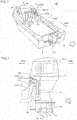
Fig. 1 is a perspective view schematically showing a marine vessel including an outboard motor according to a preferred embodiment. -
Fig. 2 is a diagram schematically showing an outboard motor according to a preferred embodiment. -
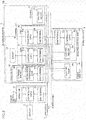
Fig. 3 is a block diagram of a marine vessel including an outboard motor according to a preferred embodiment. -
Fig. 4 is a perspective view showing an engine of an outboard motor according to a preferred embodiment. -
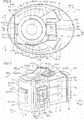
Fig. 5 is a side elevational view showing the periphery of an engine of an outboard motor according to a preferred embodiment. -
Fig. 6 is a plan view showing the periphery of an engine of an outboard motor according to a preferred embodiment. -
Fig. 7 is a perspective view showing an engine of an outboard motor according to a modified preferred embodiment. - Preferred embodiments are hereinafter described with reference to the drawings.
- The structure of a
marine vessel 100 including anoutboard motor 1 according to a preferred embodiment is now described with reference toFigs. 1 and 2 . In the figures, arrow FWD represents the forward movement direction of themarine vessel 100, and arrow BWD represents the reverse movement direction of themarine vessel 100. In the figures, arrow R represents the starboard direction of themarine vessel 100, and arrow L represents the portside direction of themarine vessel 100. In addition, a right-left direction (horizontal direction) is perpendicular to an upward-downward direction (direction Z). - As shown in
Figs. 1 and 2 , themarine vessel 100 includes theoutboard motor 1, a vessel body 2 including a rear portion (BWD side) on which theoutboard motor 1 is mounted, and a fixingbracket 3 that mounts theoutboard motor 1 on the vessel body 2. As shown inFig. 1 , themarine vessel 100 further includes aremote control unit 4 provided on the vessel body 2 and operated (used to operate the marine vessel 100) by a vessel operator and adisplay 5. Theremote control unit 4 is an example of an "external control unit". - In the
marine vessel 100, as shown inFigs. 1 and 2 , theoutboard motor 1, the fixingbracket 3, and theremote control unit 4 are communicably connected to each other by aCAN cable 6 based on the CAN communication standard. The CAN communication standard is a communication standard standardized by ISO 11898. TheCAN cable 6 includes a CANmain cable 6a, a plurality of CAN branch terminals (hubs) 6b, and a plurality ofCAN sub cables 6c connected to the CANmain cable 6a at theCAN branch terminals 6b. TheCAN cable 6 is a portion of a constituent electric cable of a wire harness and is not independent as a cable. In the figures, theCAN cable 6 is illustrated as being independent. TheCAN cable 6 is an example of a "communication cable". - As shown in
Fig. 2 , the fixingbracket 3 includes aclamp bracket 31 and abracket body 32. Theclamp bracket 31 is fixed to the stern of the vessel body 2. - As shown in
Fig. 3 , thebracket body 32 includes asteering control unit 33 and apower trim tilt 34. Thesteering control unit 33 includes a function of rotating the outboard motor 1 (outboard motor body 1a) about an axis in the upward-downward direction. Thepower trim tilt 34 includes a function of rotating the outboard motor 1 (outboard motor body 1a) about an axis in the horizontal direction (right-left direction). - The
steering control unit 33 includes anelectric motor 33a, a controller 33b including a CPU including a semiconductor device that controls the driving of theelectric motor 33a, and aCAN terminal 33c that connects the controller 33b to one of theCAN sub cables 6c of theCAN cable 6. Theelectric motor 33a rotates theoutboard motor 1 about the axis in the upward-downward direction. Thesteering control unit 33 is an example of an "external control unit". - The controller 33b is configured or programmed to acquire steering control information transmitted from an
ECU 81 described below from theCAN cable 6 via theCAN terminal 33c. The controller 33b is configured or programmed to drive theelectric motor 33a based on the steering control information. - The
power trim tilt 34 includes anelectric pump 34a. Theelectric pump 34a adjusts the amount of oil supplied to an oil bumper (not shown) to lift (tilt up) the outboard motor 1 (outboard motor body 1a) or lower (tilt down) theoutboard motor 1. At this time, theelectric pump 34a requires a large current to supply the oil to the oil bumper. - The
remote control unit 4 is used by the vessel operator to operate themarine vessel 100. Theremote control unit 4 includes acontroller 41 including a CPU including a semiconductor device, aCAN terminal 42 that connects thecontroller 41 to theCAN cable 6, and anoperator 43 that receives an operation from the vessel operator. Theoperator 43 includes a steering wheel 43a used by the vessel operator to steer the vessel body 2 (turn the outboard motor 1) and a lever 43b used by the vessel operator to manipulate the shift and output (throttle opening degree) of theoutboard motor 1. - The
controller 41 is configured or programmed to transmit an operation performed on theoperator 43 by the vessel operator as operation control information to theCAN cable 6 via theCAN terminal 42. Thecontroller 41 is configured or programmed to acquire, from theCAN cable 6 via theCAN terminal 42, display control information transmitted from theECU 81. Thecontroller 41 is configured or programmed to control thedisplay 5 to perform display based on the display control information. - As shown in
Fig. 2 , theoutboard motor 1 includes anengine 7 and apropulsion unit 11. As shown inFigs. 3 and4 , theoutboard motor 1 includes acontrol unit 8 configured or programmed to control themarine vessel 100, apower supply 12, astarter 13, and twodrivers 14. Theoutboard motor 1 includes acowling 15 in which theengine 7 is housed. Hereinafter, a side of theoutboard motor 1 mounted on the vessel body 2 is defined as a front side (FWD), and the opposite side is defined as a back side (BWD) at the steering position of theoutboard motor 1 when themarine vessel 100 moves in the forward movement direction or the reverse movement direction. In addition, a direction perpendicular to a front-back direction of theoutboard motor 1 in a horizontal plane is defined as a right-left direction of theoutboard motor 1. - As shown in
Fig. 4 , theengine 7 includes sixcylinders 71a. In the sixcylinders 71a, pistons (not shown) reciprocate in the horizontal direction. Theengine 7 is a V-type or V-shaped engine in which the sixcylinders 71a are disposed in a V-shape. Specifically, in theengine 7, a pair of cylinder groups each including threecylinders 71a are disposed in a pair ofcylinder blocks 71, respectively. The pair ofcylinder blocks 71 diverge in a V-shape from acrankcase 72. The threecylinders 71a are aligned in the upward-downward direction in each of the cylinder blocks 71. Portions of the pair ofcylinder blocks 71 opposite to thecrankcase 72 are covered with a pair ofcylinder heads 73, respectively. The cylinder blocks 71 each may be divided into a cylinder block body and a cylinder head. - A
crankshaft 72a that extends in the upward-downward direction is inserted into thecrankcase 72. Thecrankshaft 72a is rotated by a drive force of the pistons (not shown) that slide in thecylinders 71a. Aflywheel 12a described below of thepower supply 12 is mounted on an end (upper end) of thecrankshaft 72a on a Z1 side. In other words, theflywheel 12a is positioned above theengine 7. An end (lower end) of thecrankshaft 72a on a Z2 side is connected to adrive shaft 11 a (seeFig. 2 ) described below of thepropulsion unit 11. - The cylinder blocks 71 are connected to a plurality of
intake pipes 74a of anintake 74 through which intake air is supplied to therespective cylinders 71 a. The cylinder blocks 71 are connected to a plurality of exhaust pipes of an exhaust (not shown) through which exhaust air is discharged from therespective cylinders 71 a. As shown inFig. 6 , theintake pipes 74a are disposed between theengine 7 and the cowling in the horizontal direction (right-left direction). Theintake pipes 74a extend in a front-back direction while detouring in a left direction (L) or a right direction (R) so as to be away from theleft side surface 7a or theright side surface 7e of theengine 7. - As shown in
Fig. 2 , thepropulsion unit 11 converts a rotational drive force of theengine 7 into a thrust force of themarine vessel 100. Thepropulsion unit 11 includes thedrive shaft 11a connected to theengine 7, apropeller 11b, apropeller shaft 11c connected to thedrive shaft 11a and thepropeller 11b, and aswitch 11d that switches the direction of the thrust force by switching the rotational direction of thepropeller 11b. Theswitch 11d switches the direction of the thrust force based on an instruction from thecontrol unit 8. - As shown in
Fig. 3 , thecontrol unit 8 includes the ECU (engine control unit) 81 configured or programmed to mainly perform overall control of the operation etc. of themarine vessel 100 such as theengine 7 and thepropulsion unit 11 and a power management unit (PMU) 82 configured or programmed to mainly perform overall control of the power supply of theoutboard motor 1 and the fixingbracket 3. TheECU 81 and thepower management unit 82 are examples of an "engine control unit" and a "power supply control unit", respectively. - The
ECU 81 includes acontroller 81a including a CPU including a semiconductor device and aCAN terminal 81b that connects thecontroller 81a to one of theCAN sub cables 6c of theCAN cable 6. Thecontroller 81 a is an example of a "first controller". - The
controller 81 a is configured or programmed to transmit control information of the operation etc. of themarine vessel 100 to theCAN cable 6 via theCAN terminal 81b. Thecontroller 81a is configured or programmed to transmit steering control information, tilt control information, and display control information to theCAN cable 6. Thecontroller 81a is configured or programmed to acquire, from theCAN cable 6 via theCAN terminal 81b, control information of operations transmitted from theremote control unit 4, for example. - The
power management unit 82 includes acontroller 82a including a CPU including a semiconductor device and aCAN terminal 82b that connects thecontroller 82a to theCAN cable 6. Thecontroller 82a is an example of a "second controller". - The
controller 82a is configured or programmed to transmit power supply control information, for example, to theCAN cable 6 via theCAN terminal 82b. Furthermore, thecontroller 82a is configured or programmed to directly control the amount of current to theelectric pump 34a of thepower trim tilt 34. Consequently, thepower management unit 82 is configured or programmed to adjust the amount of current supplied to the power trim tilt 34 (electric pump 34a). Accordingly, when a sufficient amount of current may not be supplied to another electrical device, thepower management unit 82 reduces the amount of current supplied to thepower trim tilt 34 that requires a large amount of current, and thus failure to correctly drive another electrical device due to the tilt operation is significantly reduced or prevented. - The
ECU 81 and thepower management unit 82 are configured or programed to transmit and receive control information to and from each other via theCAN cable 6. Therefore, theECU 81 and thepower management unit 82 function as onecontrol unit 8 even in a divided state. - The
ECU 81 and thepower management unit 82 are configured or programmed to communicate with the external control units (theremote control unit 4 and the steering control unit 33) provided outside theoutboard motor body 1a. - The
ECU 81 is configured or programmed to acquire failure information of thepower management unit 82 from theCAN cable 6 via theCAN terminal 81b. Similarly, thepower management unit 82 is configured or programmed to acquire failure information of theECU 81 from theCAN cable 6 via theCAN terminal 82b. TheECU 81 and thepower management unit 82 are also configured or programmed to acquire failure information of arectification unit 12f described below and the external control units (theremote control unit 4 and the steering control unit 33) from theCAN cable 6. - According to a preferred embodiment, the
ECU 81 is mounted on theleft side surface 7a, which is a side surface of theengine 7 on an L side, as shown inFigs. 4 to 6 . Specifically, theECU 81 is mounted on theleft side surface 72b of thecrankcase 72 of theengine 7. TheECU 81 is mounted on aresin bracket 91 a having a rectangular shape elongated in the upward-downward direction. Thebracket 91a is screwed to theleft side surface 72b such that arubber vibration isolator 92a that significantly reduces or prevents transmission of vibrations of theengine 7 to thebracket 91a is held therebetween. Consequently, theECU 81 is fixed to theleft side surface 72b via thebracket 91 a and therubber vibration isolator 92a. TheECU 81 is fixed to thebracket 91a above the centers of thebracket 91a and thecrankcase 72 in the upward-downward direction. Thebracket 91 a and therubber vibration isolator 92a significantly reduce or prevent direct transmission of heat of theengine 7 to theECU 81. Theleft side surface 7a is an example of a "first side surface". - According to a preferred embodiment, the
power management unit 82 is mounted on theupper surface 7b of theengine 7. Specifically, thepower management unit 82 is mounted on both theupper surfaces 71b of the pair ofcylinder blocks 71 of theengine 7. As shown inFig. 6 , thepower management unit 82 is mounted on theupper surface 7b of theengine 7 so as to extend over aportion 7c of theengine 7 that diverges in a V-shape in a planar view. Thepower management unit 82 is mounted on theupper surface 7b directly above (corresponding positions) thecylinders 71a of theengine 7. - The
power management unit 82 is mounted on arectangular resin bracket 91b. Thebracket 91b is screwed to both a pair ofupper surfaces 71b such that arubber vibration isolator 92b (seeFigs. 4 and 5 ) is held therebetween. Consequently, thepower management unit 82 is fixed to the pair ofupper surfaces 71 b via thebracket 91b and therubber vibration isolator 92b. Thebracket 91b and therubber vibration isolator 92b significantly reduce or prevent direct transmission of the heat of theengine 7 to thepower management unit 82. - As shown in
Fig. 5 , theupper end 82c of thepower management unit 82 is positioned below (Z2 side) the upper end (height position P) of theflywheel 12a. Thus, interference of the upper end of thepower management unit 82 with a flywheel cover FC disposed above theflywheel 12a (above the engine 7) and covering theflywheel 12a is significantly reduced or prevented. InFig. 5 , the flywheel cover FC is schematically shown. - The
left side surface 7a of theengine 7 on which theECU 81 is mounted is at a position where air flow caused by air intake is likely to occur. Therefore, even when theECU 81 generates heat due to control processing of theECU 81, theECU 81 is cooled by the air flow. On the other hand, at theupper surface 7b of theengine 7 on which thepower management unit 82 is mounted, air flow caused by air intake is unlikely to occur, and heat is likely to accumulate. However, thepower management unit 82 is driven for a shorter period of time than theECU 81 such that thepower management unit 82 is unlikely to generate heat, and thus a thermal failure is unlikely to occur. - As shown in
Fig. 3 , thepower supply 12 generates electricity by the drive force of theengine 7 and supplies the generated electricity to electrical components of theoutboard motor 1 and the fixingbracket 3 via apower cable 12e. The electrical components of theoutboard motor 1 and the fixingbracket 3 include thedrivers 14, theelectric motor 33a, theelectric pump 34a, etc. In the figures other thanFig. 3 , illustration of thepower cable 12e is omitted. Thepower cable 12e is also connected to thestarter 13 that starts theengine 7. - The
power supply 12 includes theflywheel 12a that is rotated by the drive force of theengine 7 via thecrankshaft 72a, aflywheel magnet 12b that generates electricity using the rotation of theflywheel 12a, and arectification controller 12c configured or programmed to rectify the electricity generated by theflywheel magnet 12b, and aCAN terminal 12d that connects therectification controller 12c to theCAN cable 6. Therectification unit 12f includes therectification controller 12c and theCAN terminal 12d. Consequently, therectification unit 12f is communicably connected to theECU 81 and thepower management unit 82 via theCAN cable 6. Theflywheel magnet 12b is an example of a "power generator". - As shown in
Figs. 4 to 6 , therectification unit 12f is mounted on thefront side surface 7d of theengine 7. Specifically, therectification unit 12f is mounted on thefront side surface 72c of thecrankcase 72 of theengine 7. Thefront side surface 7d is an example of a "second side surface". - As shown in
Fig. 3 , thestarter 13 starts theengine 7. Thestarter 13 includes astarter motor 13a to which power is supplied from a battery (not shown) via thepower cable 12e at the time of starting. - As shown in
Figs. 4 and6 , thestarter 13 is mounted on theright side surface 7e of theengine 7, which faces theleft side surface 7a and is a side surface on an R side. Specifically, thestarter 13 is mounted over theright side surface 71c of acylinder block 71 of theengine 7 and theright side surface 72d of thecrankcase 72. Theright side surface 7e is an example of a "third side surface". - As shown in
Fig. 3 , the twodrivers 14 drive electrical components (not shown) (such as injectors provided in thecylinders 71a, respectively) of theengine 7 based on instructions from theECU 81. - As shown in
Figs. 4 and 5 , the twodrivers 14 are aligned in the upward-downward direction on thebracket 91a fixed to theleft side surface 7a of theengine 7. That is, both of the twodrivers 14 are mounted on thesame bracket 91 a on which theECU 81 is mounted. The twodrivers 14 are fixed to thebracket 91a (theleft side surface 7a of the engine 7) below theECU 81. - As shown in
Figs. 5 and6 , ahole 15a through which the CAN cable 6 (CANmain cable 6a) inside thecowling 15 is led to the outside of the cowling 15 (the outside of the outboard motor 1) is provided on thecowling 15. - According to the various preferred embodiments described above, the following advantageous effects are achieved.
- According to a preferred embodiment, the
control unit 8 is divided into theECU 81 and thepower management unit 82. Furthermore, theECU 81 is mounted on theleft side surface 7a of theengine 7, and thepower management unit 82 is mounted on theupper surface 7b of theengine 7. Accordingly, only theECU 81, which is a portion of thecontrol unit 8, is disposed on theleft side surface 7a of theengine 7, and thus interference of thecowling 15 and members (intake pipes 74a, for example) inside thecowling 15 with thecontrol unit 8 in the vicinity of theleft side surface 7a of theengine 7 is significantly reduced or prevented. Furthermore, thecontrol unit 8 is divided into theECU 81 and thepower management unit 82 such that the divided components (theECU 81 and the power management unit 82) of thecontrol unit 8 are dispersed in a relatively small empty space between theengine 7 and thecowling 15 or the members inside thecowling 15 and are mounted on theengine 7 as compared with the case where theECU 81 and thepower management unit 82 are integral and unitary with each other. Consequently, an increase in the size of thecowling 15 is significantly reduced or prevented. - According to a preferred embodiment, the
power management unit 82 is mounted on theupper surface 7b of theengine 7. Accordingly, unlike the case where thepower management unit 82 is mounted on the inner surface of an upper portion of the flywheel cover FC, the flywheel cover FC is detached to expose theengine 7 without detaching the wire harness including theCAN cable 6 connected to thepower management unit 82 as a constituent electric cable, for example. Consequently, maintenance of theoutboard motor 1 such as maintenance of theengine 7 is easily performed. - According to a preferred embodiment, the
power management unit 82 is mounted at a position on theupper surface 7b of theengine 7 that corresponds to thecylinders 71a of theengine 7. Accordingly, thepower management unit 82 is mounted at a relatively flat position that corresponds to thecylinders 71a of theengine 7 such that thepower management unit 82 is securely mounted on theengine 7. - According to a preferred embodiment, the
power management unit 82 is mounted on theupper surface 7b of theengine 7 via therubber vibration isolator 92b and thebracket 91 b. Accordingly, therubber vibration isolator 92b significantly reduces or prevents direct transmission of vibrations of thecylinders 71a to thepower management unit 82, and thus thepower management unit 82 including a semiconductor device having a relatively low resistance to vibration is protected. In addition, thepower management unit 82 is securely mounted on theengine 7 via therubber vibration isolator 92b and thebracket 91b regardless of the shape of theengine 7. - According to a preferred embodiment, the
power management unit 82 is disposed on theupper surface 7b of the V-type or V-shapedengine 7 so as to extend over theportion 7c of the V-type or V-shapedengine 7 that diverges in a V-shape in a planar view. Accordingly, the divergingportion 7c of the V-type or V-shapedengine 7 is used to ensure a large mounting area for thepower management unit 82, and thus thepower management unit 82 is easily mounted on theengine 7 even when thepower management unit 82 is relatively large. - According to a preferred embodiment, the
upper end 82c of thepower management unit 82 is disposed below the upper end (height position P) of theflywheel 12a. Accordingly, upward protrusion of thepower management unit 82 from theflywheel 12a is significantly reduced or prevented, and thus increases in the sizes of thecowling 15 and theoutboard motor 1 in the upward-downward direction are significantly reduced or prevented. - According to a preferred embodiment, the
rectification unit 12f is mounted on thefront side surface 7d different from theleft side surface 7a on which theECU 81 is mounted. Accordingly, a mounting area for theECU 81 is ensured on theleft side surface 7a as compared with the case where therectification unit 12f is mounted on theleft side surface 7a on which theECU 81 is mounted. In addition, as compared with the case where therectification unit 12f is mounted on theupper surface 7b on which thepower management unit 82 is mounted, a larger mounting area for thepower management unit 82 is ensured on theupper surface 7b. Consequently, even when thecontrol unit 8 is divided into theECU 81 and thepower management unit 82, theECU 81 and thepower management unit 82 are easily mounted on theengine 7. - According to a preferred embodiment, the
ECU 81 and thepower management unit 82 are configured or programmed to communicate with the external control units (theremote control unit 4 and the steering control unit 33) provided outside theoutboard motor body 1a via theCAN cable 6. Accordingly, theECU 81 and thepower management unit 82 communicate not only with each other but also with the external control units. Consequently, the external control units, theECU 81, and thepower management unit 82 transmit and receive information to and from each other and are able to reflect the information in control of each of the external control units, theECU 81, and thepower management unit 82. Furthermore, the control information is dispersed to theECU 81 and thepower management unit 82, and thus the load on theECU 81 and thepower management unit 82 is reduced, and the control processing time is reduced to improve the responsiveness as compared with the case where the control information from the external control units is concentrated only in one control unit. - According to a preferred embodiment, the external control unit includes the
steering control unit 33 that includes a semiconductor device and performs control of steering of theoutboard motor body 1 a with respect to the vessel body 2. Accordingly, thesteering control unit 33, theECU 81, and thepower management unit 82 transmit and receive information to and from each other and are able to reflect the information in control of each of thesteering control unit 33, theECU 81, and thepower management unit 82. - According to a preferred embodiment, the external control unit includes the
remote control unit 4 including a semiconductor device and provided on the vessel body. Accordingly, theremote control unit 4, theECU 81, and thepower management unit 82 transmit and receive information to and from each other and are able to reflect the information in control of each of theremote control unit 4, theECU 81, and thepower management unit 82. - According to a preferred embodiment, the
ECU 81 and thepower management unit 82 are configured or programmed to acquire the failure information of thepower management unit 82 and theECU 81 from each other via theCAN cable 6. Accordingly, theECU 81 is able to reflect the failure information of thepower management unit 82 in control of theECU 81. Furthermore, thepower management unit 82 is able to reflect the failure information of theECU 81 in control of thepower management unit 82. Consequently, occurrence of a failure in control of one of theECU 81 and thepower management unit 82 due to the failure information of the other of theECU 81 and thepower management unit 82 is significantly reduced or prevented. - According to a preferred embodiment, the
CAN cable 6 communicably connects therectification unit 12f, theECU 81, and thepower management unit 82 to each other. Accordingly, therectification unit 12f, theECU 81, and thepower management unit 82 transmit and receive information to and from each other and are able to reflect the information in control of each of therectification unit 12f, theECU 81, and thepower management unit 82. - According to a preferred embodiment, the
ECU 81 and thepower management unit 82 are communicably connected to each other by theCAN cable 6 based on the CAN communication standard. Accordingly, one of theECU 81 and thepower management unit 82 acquires only necessary control information of the control information transmitted from the other of theECU 81 and thepower management unit 82 via theCAN cable 6 based on the CAN communication standard as appropriate. - According to a preferred embodiment, the
drivers 14 that drive the electrical components of theengine 7 are disposed below theECU 81 on theleft side surface 7a of theengine 7. Accordingly, theECU 81 is close to thepower management unit 82 mounted on theupper surface 7b of theengine 7, and thus the length of theCAN cable 6 that connects theECU 81 to thepower management unit 82 is reduced. Consequently, interference of theCAN cable 6 with the members inside thecowling 15 is significantly reduced or prevented as compared with the case where theCAN cable 6 is long. - According to a preferred embodiment, the
starter 13 that starts theengine 7 is mounted on theright side surface 7e of theengine 7 that faces theleft side surface 7a. Accordingly, a larger mounting area for theECU 81 is ensured on theleft side surface 7a as compared with the case where thestarter 13 is mounted on theleft side surface 7a on which theECU 81 is mounted. Consequently, even when theECU 81 is relatively large, theECU 81 is easily mounted on theengine 7. - The preferred embodiments described above are illustrative in all points and not restrictive.
- For example, while the ECU 81 (engine control unit) is preferably mounted on the
left side surface 7a (first side surface) of theengine 7, and the power management unit 82 (power supply control unit) is preferably mounted on theupper surface 7b of theengine 7 in preferred embodiments described above, the present teaching is not restricted to this. As in anengine 107 according to a modified preferred embodiment shown inFig. 7 , an ECU 81 (engine control unit) may alternatively be mounted on theupper surface 7b of theengine 107, and a power management unit 82 (power supply control unit) may alternatively be mounted on theleft side surface 7a (first side surface) of theengine 107. - While the present teaching is preferably applied to the
marine vessel 100 including the vessel body 2 on which oneoutboard motor 1 is mounted in preferred embodiments described above, the present teaching is not restricted to this. The present teaching may alternatively be applied to a marine vessel including a vessel body on which a plurality of outboard motors are mounted. In this case, according to the present teaching, an increase in the size of a cowling is significantly reduced or prevented, and thus the plurality of outboard motors are easily mounted on the vessel body. Thus, the plurality of outboard motors are easily mounted on the vessel body of the marine vessel. In this case, the plurality of outboard motors are able to be communicably connected to each other by a CAN cable (communication cable). - While the ECU 81 (one of the engine control unit and the power supply control unit) is preferably mounted on the
left side surface 7a (first side surface) of theengine 7 in preferred embodiments described above, the present teaching is not restricted to this. One of the engine control unit and the power supply control unit may alternatively be disposed on any one of the side surfaces (the front side surface, the right side surface, and the rear side surface) of the engine other than the left side surface. - While the ECU 81 (one of the engine control unit and the power supply control unit) is preferably mounted on the
left side surface 7a (first side surface) of theengine 7 via thebracket 91 a, and the power management unit 82 (the other of the engine control unit and the power supply control unit) is preferably mounted on theupper surface 7b of theengine 7 via thebracket 91b in preferred embodiments described above, the present teaching is not restricted to this. The engine control unit and the power supply control unit may alternatively be mounted directly on the engine. In this case, a metal core substrate in which metal is embedded is used as a substrate including the engine control unit and the power supply control unit to efficiently dissipate heat generated in the engine control unit and the power supply control unit and heat from the engine. - While the power management unit 82 (the other of the engine control unit and the power supply control unit) is preferably mounted on the
upper surfaces 71b of the pair ofcylinder blocks 71 of theengine 7 so as to extend over theportion 7c of the V-type or V-shapedengine 7 that diverges in a V-shape in a planar view in preferred embodiments described above, the present teaching is not restricted to this. For example, the other of the engine control unit and the power supply control unit may alternatively be mounted only on the upper surface of one of the pair of the cylinder blocks. - While the present teaching is preferably applied to the V-type or V-shaped
engine 7 in preferred embodiments described above, the present teaching is not restricted to this. The present teaching may alternatively be applied to a so-called in-line engine or horizontally opposed engine. - While the
control unit 8 is preferably divided into the ECU 81 (engine control unit) and the power management unit 82 (power supply control unit) in preferred embodiments described above, the present teaching is not restricted to this. One of the engine control unit and the power supply control unit may alternatively be further divided and be disposed on the first side surface of the engine, or the other of the engine control unit and the power supply control unit may alternatively be further divided and be disposed on the upper surface of the engine. - While a plurality of control units (the ECU 81 (engine control unit), the power management unit 82 (power supply control unit), the
rectification unit 12f, and the external control units (theremote control unit 4 and he steering control unit 33)) are preferably connected to each other by theCAN cable 6 based on the CAN communication standard in preferred embodiment described above, the present teaching is not restricted to this. The plurality of control units may alternatively be connected to each other by a communication cable based on a standard other than the CAN communication standard. - While the
drivers 14 are preferably fixed to thesame bracket 91a to which the ECU 81 (one of the engine control unit and the power supply control unit) is fixed in preferred embodiment described above, the present teaching is not restricted to this. The drivers may alternatively be fixed to the same bracket to which the other of the engine control unit and the power supply control unit is fixed, or may alternatively be fixed to a separate bracket from the bracket to which the engine control unit or the power supply control unit is fixed. Furthermore, the drivers may alternatively be mounted directly on the engine.
Claims (15)
- An outboard motor (1) comprising:an engine (7) including a cylinder (71a) configured to reciprocate in a horizontal direction;a cowling (15) that covers the engine (7); anda control unit (8) divided into an engine control unit (81) including a first controller (81a) including a semiconductor device and a power supply control unit (82) configured or programmed to communicate with the engine control unit (81) and including a second controller (82a) including a semiconductor device; whereinone of the engine control unit (81) and the power supply control unit (82) is mounted on a first side surface (7a) of the engine (7), and the other of the engine control unit (81) and the power supply control unit (82) is mounted on an upper surface (7b) of the engine (7).
- The outboard motor according to claim 1, wherein the other of the engine control unit (81) and the power supply control unit (82) is mounted at a position on the upper surface (7b) of the engine (7) that corresponds to the cylinder (71a) of the engine (7), and/or
the other of the engine control unit (81) and the power supply control unit (82) is mounted on the upper surface (7b) of the engine (7) via a rubber vibration isolator (92b) and a bracket (91b), and/or
the engine (7) is a V-shaped engine; and the other of the engine control unit (81) and the power supply control unit (82) is disposed on the upper surface (7b) of the V-shaped engine so as to extend over a portion of the V-shaped engine that diverges in a V-shape in a planar view. - The outboard motor according to claim 1 or 2, further comprising a power generator (12b) configured to generate electricity by a drive force of the engine (7).
- The outboard motor according to claim 3, wherein the power generator (12b) is disposed above the engine (7), wherein an upper end of the other of the engine control unit (81) and the power supply control unit (82) is positioned below an upper end of the power generator (12b).
- The outboard motor according to claim 3 or 4, further comprising a rectification unit (12f) including a rectification controller (12c) including a semiconductor device and configured or programmed to perform control of rectifying the electricity generated by the power generator (12b).
- The outboard motor according to claim 5, wherein the rectification unit (12f) is mounted on a second side surface (7d) different from the first side surface (7a) on which the one of the engine control unit (81) and the power supply control unit (82) is mounted.
- The outboard motor according to any of claims 1 to 6, further comprising a communication cable (6) that communicably connects the engine control unit (81) to the power supply control unit (82).
- The outboard motor according to claim 7, wherein the engine control unit (81) and the power supply control unit (82) are configured or programmed to communicate with an external control unit (4, 35) provided outside an outboard motor body (1a) via the communication cable (6).
- The outboard motor according to claim 8, wherein the external control unit includes a steering control unit (35) including a semiconductor device and configured or programmed to perform control of steering of the outboard motor body (1a) with respect to a vessel body (2).
- The outboard motor according to claim 8 or 9, wherein the external control unit includes a remote control unit (4) including a semiconductor device and preferably provided on a vessel body (2).
- The outboard motor according to any of claims 7 to 10, wherein the one of the engine control unit (81) and the power supply control unit (82) is configured or programmed to acquire failure information of the other of the engine control unit (81) and the power supply control unit (82) via the communication cable (6).
- The outboard motor according to claims 3, 5, 7, preferably in combination with at least one of the claims 4 to 6 and/or 8 to 11, wherein the communication cable (6) communicably connects the rectification unit (12f), the engine control unit (81), and the power supply control unit (82) to each other.
- The outboard motor according to any of claims 7 to 12, wherein the engine control unit (81) and the power supply control unit (82) are communicably connected to each other by the communication cable (6) based on a CAN communication standard.
- The outboard motor according to any of claims 1 to 13, further comprising a driver (14) that is disposed below the one of the engine control unit (81) and the power supply control unit (82) on the first side surface (7a) of the engine (7) and is configured to drive an electrical component of the engine (7), and/or
further comprising a starter (13) that is mounted on a third side surface (7e) of the engine (7) that faces the first side surface (7a) and is configured to start the engine (7). - Marine vessel with at least one outboard motor according to any of claims 1 to 14.
Applications Claiming Priority (1)
| Application Number | Priority Date | Filing Date | Title |
|---|---|---|---|
| JP2017021924A JP6912895B2 (en) | 2017-02-09 | 2017-02-09 | Outboard motor |
Publications (2)
| Publication Number | Publication Date |
|---|---|
| EP3360776A1 true EP3360776A1 (en) | 2018-08-15 |
| EP3360776B1 EP3360776B1 (en) | 2020-08-26 |
Family
ID=61187090
Family Applications (1)
| Application Number | Title | Priority Date | Filing Date |
|---|---|---|---|
| EP18155235.7A Active EP3360776B1 (en) | 2017-02-09 | 2018-02-06 | Outboard motor |
Country Status (3)
| Country | Link |
|---|---|
| US (1) | US10464646B2 (en) |
| EP (1) | EP3360776B1 (en) |
| JP (1) | JP6912895B2 (en) |
Families Citing this family (1)
| Publication number | Priority date | Publication date | Assignee | Title |
|---|---|---|---|---|
| US20250092835A1 (en) * | 2023-09-20 | 2025-03-20 | Innotech Products LLC | Wireless throttle controller system and a method thereof |
Citations (6)
| Publication number | Priority date | Publication date | Assignee | Title |
|---|---|---|---|---|
| JPH06129258A (en) | 1992-10-09 | 1994-05-10 | Suzuki Motor Corp | Mounting equipment for electrical components of outboard motors |
| US6446593B1 (en) * | 1999-10-19 | 2002-09-10 | Sanshin Kogyo Kabushiki Kaisha | Electrical system for marine outboard drive |
| US6450847B1 (en) * | 1999-10-04 | 2002-09-17 | Sanshin Kogyo Kabushiki Kaisha | Engine component arrangement for outboard motor |
| JP2006044599A (en) * | 2004-08-09 | 2006-02-16 | Honda Motor Co Ltd | Outboard motor |
| JP2007008329A (en) * | 2005-06-30 | 2007-01-18 | Suzuki Motor Corp | Outboard motor |
| US20080119095A1 (en) * | 2006-11-20 | 2008-05-22 | Honda Motor Co., Ltd. | Outboard motor control system |
Family Cites Families (12)
| Publication number | Priority date | Publication date | Assignee | Title |
|---|---|---|---|---|
| JPH0960540A (en) * | 1995-08-25 | 1997-03-04 | Yamaha Motor Co Ltd | Internal combustion engine control unit |
| US5988130A (en) * | 1997-08-21 | 1999-11-23 | Sanshin Kogyo Kabushiki Kaisha | Electrical system for marine engine |
| JP2000248981A (en) * | 1999-02-24 | 2000-09-12 | Sanshin Ind Co Ltd | Power circuit for outboard motor |
| JP2001193549A (en) * | 1999-10-19 | 2001-07-17 | Sanshin Ind Co Ltd | Control device for outboard engine |
| US7222685B2 (en) * | 2000-09-22 | 2007-05-29 | Aisin Aw Co., Ltd. | Drive device with electronic circuit |
| US6549843B1 (en) * | 2000-11-13 | 2003-04-15 | Bombardier Motor Corporation Of America | Diagnostic system and method to temporarily adjust fuel quantity delivered to a fuel injected engine |
| JP2004106737A (en) * | 2002-09-19 | 2004-04-08 | Honda Motor Co Ltd | Outboard motor |
| JP4907935B2 (en) * | 2005-09-20 | 2012-04-04 | ヤマハ発動機株式会社 | Ship |
| JP4717576B2 (en) | 2005-09-28 | 2011-07-06 | ヤマハ発動機株式会社 | Ship |
| JP2013124714A (en) * | 2011-12-14 | 2013-06-24 | Ud Trucks Corp | Fixing member of control device |
| JP5545309B2 (en) * | 2012-03-06 | 2014-07-09 | 株式会社デンソー | Energy management system |
| JP2014013015A (en) * | 2012-07-04 | 2014-01-23 | Yamaha Motor Co Ltd | Engine system |
-
2017
- 2017-02-09 JP JP2017021924A patent/JP6912895B2/en active Active
-
2018
- 2018-01-05 US US15/862,666 patent/US10464646B2/en active Active
- 2018-02-06 EP EP18155235.7A patent/EP3360776B1/en active Active
Patent Citations (6)
| Publication number | Priority date | Publication date | Assignee | Title |
|---|---|---|---|---|
| JPH06129258A (en) | 1992-10-09 | 1994-05-10 | Suzuki Motor Corp | Mounting equipment for electrical components of outboard motors |
| US6450847B1 (en) * | 1999-10-04 | 2002-09-17 | Sanshin Kogyo Kabushiki Kaisha | Engine component arrangement for outboard motor |
| US6446593B1 (en) * | 1999-10-19 | 2002-09-10 | Sanshin Kogyo Kabushiki Kaisha | Electrical system for marine outboard drive |
| JP2006044599A (en) * | 2004-08-09 | 2006-02-16 | Honda Motor Co Ltd | Outboard motor |
| JP2007008329A (en) * | 2005-06-30 | 2007-01-18 | Suzuki Motor Corp | Outboard motor |
| US20080119095A1 (en) * | 2006-11-20 | 2008-05-22 | Honda Motor Co., Ltd. | Outboard motor control system |
Also Published As
| Publication number | Publication date |
|---|---|
| US10464646B2 (en) | 2019-11-05 |
| EP3360776B1 (en) | 2020-08-26 |
| JP6912895B2 (en) | 2021-08-04 |
| US20180222562A1 (en) | 2018-08-09 |
| JP2018127965A (en) | 2018-08-16 |
Similar Documents
| Publication | Publication Date | Title |
|---|---|---|
| US20200198748A1 (en) | Marine outboard engine cowling | |
| US20090001244A1 (en) | Engine mount system for a marine outboard engine | |
| US7470162B2 (en) | Shift system for outboard motors | |
| EP3360776B1 (en) | Outboard motor | |
| CA2131344A1 (en) | Adaptor plate mounting system for marine jet propulsion unit | |
| JPH048278B2 (en) | ||
| JP2022067892A (en) | Power source system for vessel and vessel | |
| JP6734145B2 (en) | Outboard motor | |
| JP2006290197A (en) | Outboard motor | |
| EP3343000B1 (en) | Outboard motor | |
| US20200047866A1 (en) | Outboard motor | |
| US11105260B2 (en) | Outboard motor and shift switch of outboard motor | |
| US9308981B2 (en) | Boat propulsion device | |
| JP5617413B2 (en) | Mount cooling structure for outboard motor | |
| US9371122B2 (en) | Vessel propulsion apparatus | |
| US6336835B1 (en) | Steering system of outboard motor | |
| JP5416373B2 (en) | Marine propulsion device | |
| EP4011683A2 (en) | Marine vessel power supply system, marine vessel and marine vessel power supply method | |
| JPH10223111A (en) | Outboard relay | |
| US7872196B2 (en) | Electrical component box for water vehicle | |
| JP3329219B2 (en) | Outboard motor electrical component installation structure | |
| JP2004203230A (en) | Outboard motor | |
| US20150151820A1 (en) | Boat propulsion device | |
| JP5605055B2 (en) | Outboard motor mounting device | |
| JP2000320441A (en) | Outboard motor electrical component mounting structure |
Legal Events
| Date | Code | Title | Description |
|---|---|---|---|
| PUAI | Public reference made under article 153(3) epc to a published international application that has entered the european phase |
Free format text: ORIGINAL CODE: 0009012 |
|
| STAA | Information on the status of an ep patent application or granted ep patent |
Free format text: STATUS: THE APPLICATION HAS BEEN PUBLISHED |
|
| AK | Designated contracting states |
Kind code of ref document: A1 Designated state(s): AL AT BE BG CH CY CZ DE DK EE ES FI FR GB GR HR HU IE IS IT LI LT LU LV MC MK MT NL NO PL PT RO RS SE SI SK SM TR |
|
| AX | Request for extension of the european patent |
Extension state: BA ME |
|
| STAA | Information on the status of an ep patent application or granted ep patent |
Free format text: STATUS: REQUEST FOR EXAMINATION WAS MADE |
|
| STAA | Information on the status of an ep patent application or granted ep patent |
Free format text: STATUS: EXAMINATION IS IN PROGRESS |
|
| 17P | Request for examination filed |
Effective date: 20190211 |
|
| RBV | Designated contracting states (corrected) |
Designated state(s): AL AT BE BG CH CY CZ DE DK EE ES FI FR GB GR HR HU IE IS IT LI LT LU LV MC MK MT NL NO PL PT RO RS SE SI SK SM TR |
|
| 17Q | First examination report despatched |
Effective date: 20190306 |
|
| GRAP | Despatch of communication of intention to grant a patent |
Free format text: ORIGINAL CODE: EPIDOSNIGR1 |
|
| STAA | Information on the status of an ep patent application or granted ep patent |
Free format text: STATUS: GRANT OF PATENT IS INTENDED |
|
| GRAJ | Information related to disapproval of communication of intention to grant by the applicant or resumption of examination proceedings by the epo deleted |
Free format text: ORIGINAL CODE: EPIDOSDIGR1 |
|
| GRAP | Despatch of communication of intention to grant a patent |
Free format text: ORIGINAL CODE: EPIDOSNIGR1 |
|
| INTG | Intention to grant announced |
Effective date: 20200319 |
|
| INTG | Intention to grant announced |
Effective date: 20200327 |
|
| INTG | Intention to grant announced |
Effective date: 20200327 |
|
| INTG | Intention to grant announced |
Effective date: 20200408 |
|
| INTG | Intention to grant announced |
Effective date: 20200416 |
|
| GRAS | Grant fee paid |
Free format text: ORIGINAL CODE: EPIDOSNIGR3 |
|
| GRAA | (expected) grant |
Free format text: ORIGINAL CODE: 0009210 |
|
| STAA | Information on the status of an ep patent application or granted ep patent |
Free format text: STATUS: THE PATENT HAS BEEN GRANTED |
|
| AK | Designated contracting states |
Kind code of ref document: B1 Designated state(s): AL AT BE BG CH CY CZ DE DK EE ES FI FR GB GR HR HU IE IS IT LI LT LU LV MC MK MT NL NO PL PT RO RS SE SI SK SM TR |
|
| REG | Reference to a national code |
Ref country code: GB Ref legal event code: FG4D |
|
| REG | Reference to a national code |
Ref country code: CH Ref legal event code: EP |
|
| REG | Reference to a national code |
Ref country code: AT Ref legal event code: REF Ref document number: 1306124 Country of ref document: AT Kind code of ref document: T Effective date: 20200915 |
|
| REG | Reference to a national code |
Ref country code: IE Ref legal event code: FG4D |
|
| REG | Reference to a national code |
Ref country code: DE Ref legal event code: R096 Ref document number: 602018007160 Country of ref document: DE |
|
| REG | Reference to a national code |
Ref country code: LT Ref legal event code: MG4D |
|
| PG25 | Lapsed in a contracting state [announced via postgrant information from national office to epo] |
Ref country code: BG Free format text: LAPSE BECAUSE OF FAILURE TO SUBMIT A TRANSLATION OF THE DESCRIPTION OR TO PAY THE FEE WITHIN THE PRESCRIBED TIME-LIMIT Effective date: 20201126 Ref country code: PT Free format text: LAPSE BECAUSE OF FAILURE TO SUBMIT A TRANSLATION OF THE DESCRIPTION OR TO PAY THE FEE WITHIN THE PRESCRIBED TIME-LIMIT Effective date: 20201228 Ref country code: FI Free format text: LAPSE BECAUSE OF FAILURE TO SUBMIT A TRANSLATION OF THE DESCRIPTION OR TO PAY THE FEE WITHIN THE PRESCRIBED TIME-LIMIT Effective date: 20200826 Ref country code: NO Free format text: LAPSE BECAUSE OF FAILURE TO SUBMIT A TRANSLATION OF THE DESCRIPTION OR TO PAY THE FEE WITHIN THE PRESCRIBED TIME-LIMIT Effective date: 20201126 Ref country code: GR Free format text: LAPSE BECAUSE OF FAILURE TO SUBMIT A TRANSLATION OF THE DESCRIPTION OR TO PAY THE FEE WITHIN THE PRESCRIBED TIME-LIMIT Effective date: 20201127 Ref country code: SE Free format text: LAPSE BECAUSE OF FAILURE TO SUBMIT A TRANSLATION OF THE DESCRIPTION OR TO PAY THE FEE WITHIN THE PRESCRIBED TIME-LIMIT Effective date: 20200826 Ref country code: HR Free format text: LAPSE BECAUSE OF FAILURE TO SUBMIT A TRANSLATION OF THE DESCRIPTION OR TO PAY THE FEE WITHIN THE PRESCRIBED TIME-LIMIT Effective date: 20200826 Ref country code: LT Free format text: LAPSE BECAUSE OF FAILURE TO SUBMIT A TRANSLATION OF THE DESCRIPTION OR TO PAY THE FEE WITHIN THE PRESCRIBED TIME-LIMIT Effective date: 20200826 |
|
| REG | Reference to a national code |
Ref country code: NL Ref legal event code: MP Effective date: 20200826 |
|
| REG | Reference to a national code |
Ref country code: AT Ref legal event code: MK05 Ref document number: 1306124 Country of ref document: AT Kind code of ref document: T Effective date: 20200826 |
|
| PG25 | Lapsed in a contracting state [announced via postgrant information from national office to epo] |
Ref country code: IS Free format text: LAPSE BECAUSE OF FAILURE TO SUBMIT A TRANSLATION OF THE DESCRIPTION OR TO PAY THE FEE WITHIN THE PRESCRIBED TIME-LIMIT Effective date: 20201226 Ref country code: PL Free format text: LAPSE BECAUSE OF FAILURE TO SUBMIT A TRANSLATION OF THE DESCRIPTION OR TO PAY THE FEE WITHIN THE PRESCRIBED TIME-LIMIT Effective date: 20200826 Ref country code: LV Free format text: LAPSE BECAUSE OF FAILURE TO SUBMIT A TRANSLATION OF THE DESCRIPTION OR TO PAY THE FEE WITHIN THE PRESCRIBED TIME-LIMIT Effective date: 20200826 Ref country code: RS Free format text: LAPSE BECAUSE OF FAILURE TO SUBMIT A TRANSLATION OF THE DESCRIPTION OR TO PAY THE FEE WITHIN THE PRESCRIBED TIME-LIMIT Effective date: 20200826 Ref country code: NL Free format text: LAPSE BECAUSE OF FAILURE TO SUBMIT A TRANSLATION OF THE DESCRIPTION OR TO PAY THE FEE WITHIN THE PRESCRIBED TIME-LIMIT Effective date: 20200826 |
|
| PG25 | Lapsed in a contracting state [announced via postgrant information from national office to epo] |
Ref country code: CZ Free format text: LAPSE BECAUSE OF FAILURE TO SUBMIT A TRANSLATION OF THE DESCRIPTION OR TO PAY THE FEE WITHIN THE PRESCRIBED TIME-LIMIT Effective date: 20200826 Ref country code: DK Free format text: LAPSE BECAUSE OF FAILURE TO SUBMIT A TRANSLATION OF THE DESCRIPTION OR TO PAY THE FEE WITHIN THE PRESCRIBED TIME-LIMIT Effective date: 20200826 Ref country code: RO Free format text: LAPSE BECAUSE OF FAILURE TO SUBMIT A TRANSLATION OF THE DESCRIPTION OR TO PAY THE FEE WITHIN THE PRESCRIBED TIME-LIMIT Effective date: 20200826 Ref country code: EE Free format text: LAPSE BECAUSE OF FAILURE TO SUBMIT A TRANSLATION OF THE DESCRIPTION OR TO PAY THE FEE WITHIN THE PRESCRIBED TIME-LIMIT Effective date: 20200826 Ref country code: SM Free format text: LAPSE BECAUSE OF FAILURE TO SUBMIT A TRANSLATION OF THE DESCRIPTION OR TO PAY THE FEE WITHIN THE PRESCRIBED TIME-LIMIT Effective date: 20200826 |
|
| REG | Reference to a national code |
Ref country code: DE Ref legal event code: R097 Ref document number: 602018007160 Country of ref document: DE |
|
| PG25 | Lapsed in a contracting state [announced via postgrant information from national office to epo] |
Ref country code: ES Free format text: LAPSE BECAUSE OF FAILURE TO SUBMIT A TRANSLATION OF THE DESCRIPTION OR TO PAY THE FEE WITHIN THE PRESCRIBED TIME-LIMIT Effective date: 20200826 Ref country code: AL Free format text: LAPSE BECAUSE OF FAILURE TO SUBMIT A TRANSLATION OF THE DESCRIPTION OR TO PAY THE FEE WITHIN THE PRESCRIBED TIME-LIMIT Effective date: 20200826 Ref country code: AT Free format text: LAPSE BECAUSE OF FAILURE TO SUBMIT A TRANSLATION OF THE DESCRIPTION OR TO PAY THE FEE WITHIN THE PRESCRIBED TIME-LIMIT Effective date: 20200826 |
|
| PG25 | Lapsed in a contracting state [announced via postgrant information from national office to epo] |
Ref country code: SK Free format text: LAPSE BECAUSE OF FAILURE TO SUBMIT A TRANSLATION OF THE DESCRIPTION OR TO PAY THE FEE WITHIN THE PRESCRIBED TIME-LIMIT Effective date: 20200826 |
|
| PLBE | No opposition filed within time limit |
Free format text: ORIGINAL CODE: 0009261 |
|
| STAA | Information on the status of an ep patent application or granted ep patent |
Free format text: STATUS: NO OPPOSITION FILED WITHIN TIME LIMIT |
|
| 26N | No opposition filed |
Effective date: 20210527 |
|
| PG25 | Lapsed in a contracting state [announced via postgrant information from national office to epo] |
Ref country code: SI Free format text: LAPSE BECAUSE OF FAILURE TO SUBMIT A TRANSLATION OF THE DESCRIPTION OR TO PAY THE FEE WITHIN THE PRESCRIBED TIME-LIMIT Effective date: 20200826 |
|
| REG | Reference to a national code |
Ref country code: DE Ref legal event code: R119 Ref document number: 602018007160 Country of ref document: DE |
|
| PG25 | Lapsed in a contracting state [announced via postgrant information from national office to epo] |
Ref country code: MC Free format text: LAPSE BECAUSE OF FAILURE TO SUBMIT A TRANSLATION OF THE DESCRIPTION OR TO PAY THE FEE WITHIN THE PRESCRIBED TIME-LIMIT Effective date: 20200826 |
|
| REG | Reference to a national code |
Ref country code: BE Ref legal event code: MM Effective date: 20210228 |
|
| PG25 | Lapsed in a contracting state [announced via postgrant information from national office to epo] |
Ref country code: LU Free format text: LAPSE BECAUSE OF NON-PAYMENT OF DUE FEES Effective date: 20210206 Ref country code: LI Free format text: LAPSE BECAUSE OF NON-PAYMENT OF DUE FEES Effective date: 20210228 Ref country code: CH Free format text: LAPSE BECAUSE OF NON-PAYMENT OF DUE FEES Effective date: 20210228 |
|
| PG25 | Lapsed in a contracting state [announced via postgrant information from national office to epo] |
Ref country code: IE Free format text: LAPSE BECAUSE OF NON-PAYMENT OF DUE FEES Effective date: 20210206 Ref country code: DE Free format text: LAPSE BECAUSE OF NON-PAYMENT OF DUE FEES Effective date: 20210901 |
|
| PG25 | Lapsed in a contracting state [announced via postgrant information from national office to epo] |
Ref country code: BE Free format text: LAPSE BECAUSE OF NON-PAYMENT OF DUE FEES Effective date: 20210228 |
|
| GBPC | Gb: european patent ceased through non-payment of renewal fee |
Effective date: 20220206 |
|
| PG25 | Lapsed in a contracting state [announced via postgrant information from national office to epo] |
Ref country code: GB Free format text: LAPSE BECAUSE OF NON-PAYMENT OF DUE FEES Effective date: 20220206 |
|
| PG25 | Lapsed in a contracting state [announced via postgrant information from national office to epo] |
Ref country code: CY Free format text: LAPSE BECAUSE OF FAILURE TO SUBMIT A TRANSLATION OF THE DESCRIPTION OR TO PAY THE FEE WITHIN THE PRESCRIBED TIME-LIMIT Effective date: 20200826 |
|
| P01 | Opt-out of the competence of the unified patent court (upc) registered |
Effective date: 20230527 |
|
| PG25 | Lapsed in a contracting state [announced via postgrant information from national office to epo] |
Ref country code: HU Free format text: LAPSE BECAUSE OF FAILURE TO SUBMIT A TRANSLATION OF THE DESCRIPTION OR TO PAY THE FEE WITHIN THE PRESCRIBED TIME-LIMIT; INVALID AB INITIO Effective date: 20180206 |
|
| PG25 | Lapsed in a contracting state [announced via postgrant information from national office to epo] |
Ref country code: MK Free format text: LAPSE BECAUSE OF FAILURE TO SUBMIT A TRANSLATION OF THE DESCRIPTION OR TO PAY THE FEE WITHIN THE PRESCRIBED TIME-LIMIT Effective date: 20200826 |
|
| PG25 | Lapsed in a contracting state [announced via postgrant information from national office to epo] |
Ref country code: TR Free format text: LAPSE BECAUSE OF FAILURE TO SUBMIT A TRANSLATION OF THE DESCRIPTION OR TO PAY THE FEE WITHIN THE PRESCRIBED TIME-LIMIT Effective date: 20200826 |
|
| PG25 | Lapsed in a contracting state [announced via postgrant information from national office to epo] |
Ref country code: MT Free format text: LAPSE BECAUSE OF FAILURE TO SUBMIT A TRANSLATION OF THE DESCRIPTION OR TO PAY THE FEE WITHIN THE PRESCRIBED TIME-LIMIT Effective date: 20200826 |
|
| PGFP | Annual fee paid to national office [announced via postgrant information from national office to epo] |
Ref country code: IT Payment date: 20260224 Year of fee payment: 9 |
|
| PGFP | Annual fee paid to national office [announced via postgrant information from national office to epo] |
Ref country code: FR Payment date: 20260218 Year of fee payment: 9 |