EP3360749A1 - Driving improvement detection device and driving improvement detection system - Google Patents
Driving improvement detection device and driving improvement detection system Download PDFInfo
- Publication number
- EP3360749A1 EP3360749A1 EP16863818.7A EP16863818A EP3360749A1 EP 3360749 A1 EP3360749 A1 EP 3360749A1 EP 16863818 A EP16863818 A EP 16863818A EP 3360749 A1 EP3360749 A1 EP 3360749A1
- Authority
- EP
- European Patent Office
- Prior art keywords
- driving behavior
- acceleration
- driving
- behavior data
- data
- Prior art date
- Legal status (The legal status is an assumption and is not a legal conclusion. Google has not performed a legal analysis and makes no representation as to the accuracy of the status listed.)
- Withdrawn
Links
- 238000001514 detection method Methods 0.000 title claims abstract description 55
- 230000001133 acceleration Effects 0.000 claims abstract description 100
- 230000036461 convulsion Effects 0.000 claims abstract description 46
- 230000008859 change Effects 0.000 claims abstract description 16
- 238000004891 communication Methods 0.000 claims description 41
- 238000012546 transfer Methods 0.000 claims description 3
- 230000006399 behavior Effects 0.000 description 144
- 238000010586 diagram Methods 0.000 description 19
- 238000013500 data storage Methods 0.000 description 14
- 230000006870 function Effects 0.000 description 14
- 238000000034 method Methods 0.000 description 12
- 238000005070 sampling Methods 0.000 description 9
- 239000000470 constituent Substances 0.000 description 6
- 238000005259 measurement Methods 0.000 description 6
- 230000007704 transition Effects 0.000 description 6
- 230000008569 process Effects 0.000 description 5
- 238000004364 calculation method Methods 0.000 description 4
- 239000004065 semiconductor Substances 0.000 description 3
- 238000007792 addition Methods 0.000 description 2
- 238000003384 imaging method Methods 0.000 description 2
- 239000004973 liquid crystal related substance Substances 0.000 description 2
- 238000006467 substitution reaction Methods 0.000 description 2
- 101000822695 Clostridium perfringens (strain 13 / Type A) Small, acid-soluble spore protein C1 Proteins 0.000 description 1
- 101000655262 Clostridium perfringens (strain 13 / Type A) Small, acid-soluble spore protein C2 Proteins 0.000 description 1
- 101000655256 Paraclostridium bifermentans Small, acid-soluble spore protein alpha Proteins 0.000 description 1
- 101000655264 Paraclostridium bifermentans Small, acid-soluble spore protein beta Proteins 0.000 description 1
- 230000005540 biological transmission Effects 0.000 description 1
- 239000012141 concentrate Substances 0.000 description 1
- 230000004069 differentiation Effects 0.000 description 1
- 230000010365 information processing Effects 0.000 description 1
- 238000011160 research Methods 0.000 description 1
Images







Classifications
-
- B—PERFORMING OPERATIONS; TRANSPORTING
- B60—VEHICLES IN GENERAL
- B60W—CONJOINT CONTROL OF VEHICLE SUB-UNITS OF DIFFERENT TYPE OR DIFFERENT FUNCTION; CONTROL SYSTEMS SPECIALLY ADAPTED FOR HYBRID VEHICLES; ROAD VEHICLE DRIVE CONTROL SYSTEMS FOR PURPOSES NOT RELATED TO THE CONTROL OF A PARTICULAR SUB-UNIT
- B60W40/00—Estimation or calculation of non-directly measurable driving parameters for road vehicle drive control systems not related to the control of a particular sub unit, e.g. by using mathematical models
- B60W40/08—Estimation or calculation of non-directly measurable driving parameters for road vehicle drive control systems not related to the control of a particular sub unit, e.g. by using mathematical models related to drivers or passengers
- B60W40/09—Driving style or behaviour
-
- B—PERFORMING OPERATIONS; TRANSPORTING
- B60—VEHICLES IN GENERAL
- B60W—CONJOINT CONTROL OF VEHICLE SUB-UNITS OF DIFFERENT TYPE OR DIFFERENT FUNCTION; CONTROL SYSTEMS SPECIALLY ADAPTED FOR HYBRID VEHICLES; ROAD VEHICLE DRIVE CONTROL SYSTEMS FOR PURPOSES NOT RELATED TO THE CONTROL OF A PARTICULAR SUB-UNIT
- B60W40/00—Estimation or calculation of non-directly measurable driving parameters for road vehicle drive control systems not related to the control of a particular sub unit, e.g. by using mathematical models
- B60W40/10—Estimation or calculation of non-directly measurable driving parameters for road vehicle drive control systems not related to the control of a particular sub unit, e.g. by using mathematical models related to vehicle motion
- B60W40/107—Longitudinal acceleration
-
- B—PERFORMING OPERATIONS; TRANSPORTING
- B60—VEHICLES IN GENERAL
- B60W—CONJOINT CONTROL OF VEHICLE SUB-UNITS OF DIFFERENT TYPE OR DIFFERENT FUNCTION; CONTROL SYSTEMS SPECIALLY ADAPTED FOR HYBRID VEHICLES; ROAD VEHICLE DRIVE CONTROL SYSTEMS FOR PURPOSES NOT RELATED TO THE CONTROL OF A PARTICULAR SUB-UNIT
- B60W50/00—Details of control systems for road vehicle drive control not related to the control of a particular sub-unit, e.g. process diagnostic or vehicle driver interfaces
- B60W2050/0062—Adapting control system settings
- B60W2050/0075—Automatic parameter input, automatic initialising or calibrating means
-
- B—PERFORMING OPERATIONS; TRANSPORTING
- B60—VEHICLES IN GENERAL
- B60W—CONJOINT CONTROL OF VEHICLE SUB-UNITS OF DIFFERENT TYPE OR DIFFERENT FUNCTION; CONTROL SYSTEMS SPECIALLY ADAPTED FOR HYBRID VEHICLES; ROAD VEHICLE DRIVE CONTROL SYSTEMS FOR PURPOSES NOT RELATED TO THE CONTROL OF A PARTICULAR SUB-UNIT
- B60W2520/00—Input parameters relating to overall vehicle dynamics
- B60W2520/10—Longitudinal speed
- B60W2520/105—Longitudinal acceleration
-
- B—PERFORMING OPERATIONS; TRANSPORTING
- B60—VEHICLES IN GENERAL
- B60W—CONJOINT CONTROL OF VEHICLE SUB-UNITS OF DIFFERENT TYPE OR DIFFERENT FUNCTION; CONTROL SYSTEMS SPECIALLY ADAPTED FOR HYBRID VEHICLES; ROAD VEHICLE DRIVE CONTROL SYSTEMS FOR PURPOSES NOT RELATED TO THE CONTROL OF A PARTICULAR SUB-UNIT
- B60W2556/00—Input parameters relating to data
- B60W2556/45—External transmission of data to or from the vehicle
-
- B—PERFORMING OPERATIONS; TRANSPORTING
- B60—VEHICLES IN GENERAL
- B60W—CONJOINT CONTROL OF VEHICLE SUB-UNITS OF DIFFERENT TYPE OR DIFFERENT FUNCTION; CONTROL SYSTEMS SPECIALLY ADAPTED FOR HYBRID VEHICLES; ROAD VEHICLE DRIVE CONTROL SYSTEMS FOR PURPOSES NOT RELATED TO THE CONTROL OF A PARTICULAR SUB-UNIT
- B60W2556/00—Input parameters relating to data
- B60W2556/45—External transmission of data to or from the vehicle
- B60W2556/55—External transmission of data to or from the vehicle using telemetry
-
- B—PERFORMING OPERATIONS; TRANSPORTING
- B60—VEHICLES IN GENERAL
- B60W—CONJOINT CONTROL OF VEHICLE SUB-UNITS OF DIFFERENT TYPE OR DIFFERENT FUNCTION; CONTROL SYSTEMS SPECIALLY ADAPTED FOR HYBRID VEHICLES; ROAD VEHICLE DRIVE CONTROL SYSTEMS FOR PURPOSES NOT RELATED TO THE CONTROL OF A PARTICULAR SUB-UNIT
- B60W2720/00—Output or target parameters relating to overall vehicle dynamics
- B60W2720/10—Longitudinal speed
- B60W2720/106—Longitudinal acceleration
Definitions
- the RAM 46 is a storage device that temporarily stores programs and data, and functions as a working area for the controller 41.
- the data storage unit 47 is a recording medium for storing programs and various pieces of data, and can be realized by a recording medium such as a hard disk, a semiconductor memory, or a detachable memory card.
- a program (OS, application program 47a) to be executed by the controller 41 and data are stored in the data storage unit 47.
- the RAM 56 is a storage device for temporarily storing programs and data and functions as a work area of the controller 51.
- the data storage unit 57 is a recording medium that stores parameters, data, and programs necessary for implementing functions, and stores control programs executed by the controller 51 and various pieces of data.
- the data storage unit 51 is realized by, for example, a hard disk (HDD) or a semiconductor storage device (SSD).
- the control program 57a is installed for implementing functions described later. By executing this control program 57a, the controller 51 implements various functions described later.
- the data storage unit 57 also stores a database 57b relating to the driving behavior of the driver.
- the data storage unit 57 also functions as a working area of the controller 51.
Landscapes
- Engineering & Computer Science (AREA)
- Physics & Mathematics (AREA)
- Automation & Control Theory (AREA)
- Mathematical Physics (AREA)
- Transportation (AREA)
- Mechanical Engineering (AREA)
- Traffic Control Systems (AREA)
- Control Of Driving Devices And Active Controlling Of Vehicle (AREA)
Abstract
Description
- The present disclosure relates to a driving behavior detection device and a driving behavior system that detect a driving behavior of a driver of a vehicle.
-
Patent Document 1 discloses a vehicle driving support device that determines a state of operation of driving a vehicle based on an amount of change in acceleration or the like. - The vehicle driving support device disclosed in
Patent Document 1 includes amount-of-change calculation means that calculates a first related value related to an amount of change in acceleration of the vehicle, jerk calculation means that calculates a second related value related to jerk of the vehicle, acceleration calculation means that calculates a third related value related to an absolute value of acceleration of the vehicle, and state determination means that determines a state of operation of driving the vehicle based on the first to third related values. - When the first related value calculated by the amount-of-change calculation means is not smaller than a predetermined value, the state determination means determines the state of operation of driving a vehicle in accordance with a predetermined determination criterion by using a first determination map. The determination criterion is set based on a ratio of kinetic energy of a mass point when a change in acceleration of the vehicle ends to an amount of change in acceleration. The kinetic energy of the mass point is calculated using a vibration model representing the movement of the mass point in a vehicle interior based on the first and second related values. When the first related value is smaller than the predetermined value, the state determination means uses a second determination map different from the first determination map to determine the state of operation of driving the vehicle based on the first and third related values. With this configuration, it is possible to accurately determine the state of operation of driving the vehicle irrespective of the amount of change in acceleration.
- Patent Document 1: Japanese Unexamined Patent Application Publication No.
2012-198345 - The present disclosure provides a driving behavior detection device and a driving behavior system capable of accurately detecting a driving behavior of a driver of a vehicle.
- A driving behavior detection device of the present disclosure includes an acquisition unit configured to acquire information indicating an acceleration of a vehicle, and a computing unit configured to generate driving behavior data indicating a driving behavior of a driver of the vehicle based on time series of behavior data indicating an acceleration of the vehicle and a jerk that is a change rate of the acceleration. The computing unit sets a determination plane with coordinate axes set for the acceleration and the jerk, sets, on the determination plane, a first area in which the acceleration is equal to or smaller than a first predetermined value and the jerk is equal to or smaller than a second predetermined value, as an area indicating safe driving, and sets a second area other than the first area, as an area indicating non-safe driving. The computing unit generates the driving behavior data based on the behavior data disposed in the first and second areas.
- A first driving behavior detection system of the present disclosure incudes the driving behavior detection device described above, a mobile terminal configured to receive the driving behavior data from the driving behavior detection device and transfer the driving behavior data to an external device, and a server configured to receive the driving behavior data from the mobile terminal and store the driving behavior data into a storage unit.
- A second driving behavior detection system of the present disclosure includes the driving behavior detection device described above, and a server configured to receive the driving behavior data from the driving behavior detection device and store the driving behavior data into a storage means.
- According to the driving behavior detection device and the driving behavior system of the present disclosure, the driving behavior of the driver is detected based on the area of the determination plane with coordinate axes set for the acceleration and the jerk, so that the driving behavior of the driver of the vehicle can be detected accurately.
-
-
FIG. 1 is a diagram showing a configuration of a driving behavior detection system in a first embodiment of the present disclosure. -
FIG. 2 is a block diagram showing a configuration of a telemeter unit in the first embodiment. -
FIG. 3 is a block diagram showing a configuration of a mobile terminal in the first embodiment. -
FIG. 4 is a block diagram showing a configuration of a data server in the first embodiment. -
FIG. 5 is a diagram for describing a transition of driving behavior data in the first embodiment. -
FIG. 6 is a graph illustrating a change in vehicle speed when sudden braking is applied while a vehicle is descending a slope. -
FIG. 7 is a graph illustrating a change in acceleration when sudden braking is applied while the vehicle is descending a slope. -
FIG. 8 is a graph for describing a J (jerk) - G (acceleration) plane. -
FIG. 9 is a graph illustrating a two-dimensional threshold for driving behavior determination, set on the J (jerk) - G (acceleration) plane. -
FIG. 10 is a flowchart showing a generation process for driving behavior data. -
FIG. 11 is a diagram for describing significance of driving behavior data obtained by a driving behavior detection system of the present disclosure. -
FIG. 12 is a diagram showing a configuration of a driving behavior detection system in a second embodiment of the present disclosure. -
FIG. 13 is a diagram for describing a transition of driving behavior data in the second embodiment. -
FIG. 14 is a diagram showing a configuration of a driving behavior detection system in a third embodiment of the present disclosure. -
FIG. 15 is a diagram for describing a transition of driving behavior data in the third embodiment. - Some embodiments are described in detail below with reference to the drawings as appropriate. However, description explained in detail more than necessary may be omitted. For example, detailed description of already well-known matters and redundant description on substantially the same configuration may be omitted. This is to avoid the unnecessary redundancy of the following description and to facilitate understanding by those skilled in the art.
- In addition, the inventor(s) provide(s) the accompanying drawings and the following description in order to enable those skilled in the art to sufficiently understand the present disclosure, which is not intended to limit the claimed subject matter.
- Hereinafter, an embodiment of a driving behavior detection system according to the present invention is described with reference to the accompanying drawings. The driving behavior detection system described in the following embodiment is a system for detecting a driving behavior of a driver for a vehicle.
FIG. 1 shows the configuration of the driving behavior detection system according to an embodiment of the present disclosure. - As shown in
FIG. 1 , a drivingbehavior detection system 100 includes atelemeter unit 10, amobile terminal 40, and adata server 50. Thetelemeter unit 10 is disposed in avehicle 30, detects a behavior of thevehicle 30 while thevehicle 30 is driven, obtains data indicating the driving behavior (or driving operation state) of the driver for the vehicle (hereinafter referred to as "driving behavior data") based on the detected behavior, and transmits the obtained data to the outside. Themobile terminal 40 receives the driving behavior data from thetelemeter unit 10 and transmits the received data to thedata server 50 via anetwork 200. Thedata server 50 updates the database based on the received driving behavior data. - Specific configurations of elements of the
telemeter unit 10,mobile terminal 40 anddata server 50 are described below. -
FIG. 2 is a diagram illustrating the configuration of thetelemeter unit 10. Thetelemeter unit 10 includes acontroller 11, anacceleration sensor 15, acommunication interface 18 that enables wireless communication with other electronic devices in accordance with a communication standard such as WiFi or Bluetooth (registered trademark), and amemory 17 that stores data and the like. - The
controller 11 is realized by a CPU or an MPU, and executes a program stored in amemory 17 to achieve a predetermined function described later. The program to be executed by thecontroller 11 may be provided via thenetwork 200 or a recording medium such as a CD-ROM. - The
acceleration sensor 15 is a sensor that detects accelerations of thevehicle 30 in three orthogonal directions (X, Y, Z directions). It is assumed here that the width direction of thevehicle 30 is the X direction, the traveling direction (forward direction) of thevehicle 30 is the Y direction, and the upward direction (zenith direction) of thevehicle 30 is the Z direction. - The
memory 17 is a recording medium for storing various pieces of data and is realized by, for example, a semiconductor memory element such as a flash memory. Thememory 17 stores data and programs executed by thecontroller 11. Instead of thememory 17, a recording medium such as a detachable memory card or a hard disk may be used. - The
communication interface 18 is a module that performs wireless communication in accordance with the communication standard such as Wi-Fi or Bluetooth. Thecommunication interface 18 may perform communication in accordance with a communication standard such as LTE or 3G. Note that thecommunication interface 18 is not limited to wireless communication but may be one that performs wired communication. - The
mobile terminal 40 can communicate with thetelemeter unit 10. Further, themobile terminal 40 can transmit information to thedata server 50 via thenetwork 200. In the present embodiment, a smartphone is assumed as an example of themobile terminal 40, but themobile terminal 40 may be a PDA, a mobile phone, or the like. -
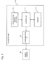
FIG. 3 is a diagram illustrating the configuration of themobile terminal 40. Themobile terminal 40 includes animaging unit 42 for capturing images, adisplay unit 43 for displaying information such as images, and anoperation unit 45. Further, themobile terminal 40 includes afirst communication interface 48 for communication with a network and asecond communication interface 49 for communication with another electronic device. Moreover, themobile terminal 40 includes aRAM 46 and adata storage unit 47 for storing data and the like, and acontroller 41 for controlling the overall operation of themobile terminal 40. Themobile terminal 40 may include an acceleration sensor as described later. - The
imaging unit 42 includes an image sensor such as a CCD or a CMOS image sensor, and captures an image of the subject to generate image data. - The
display unit 43 is realized by, for example, a liquid crystal display or an organic EL display. Theoperation unit 45 includes a touch panel disposed on the upper surface of thedisplay unit 43 and configured to accept a touch operation by a user. Theoperation unit 45 further includes operation buttons. The operation buttons include buttons physically provided in the main body of themobile terminal 40 and virtual buttons realized by thedisplay unit 43 and the touch panel function. - The
first communication interface 48 is a communication module for connecting to the network and performs communication in accordance with the communication standard such as LTE or 3G. Thesecond communication interface 49 is a communication module for wirelessly communicating with another electronic device at a relatively short distance and performs communication in accordance with the communication standard such as Wi-Fi or Bluetooth. Thesecond communication interface 49 may be one which communicates with another electronic device via a cable, and for example, thesecond communication interface 49 may perform data communication in accordance with a standard such as USB (Universal Serial Bus) or HDMI (High Definition Multimedia Interface) (registered trademark)). - The
RAM 46 is a storage device that temporarily stores programs and data, and functions as a working area for thecontroller 41. Thedata storage unit 47 is a recording medium for storing programs and various pieces of data, and can be realized by a recording medium such as a hard disk, a semiconductor memory, or a detachable memory card. A program (OS,application program 47a) to be executed by thecontroller 41 and data are stored in thedata storage unit 47. - The
controller 41 is realized by a CPU or an MPU, and executes anapplication program 47a stored in thedata storage unit 47, thereby implementing a predetermined function described later. Theapplication program 47a may be provided via thenetwork 200 or may be provided by a recording medium such as a CD-ROM. -
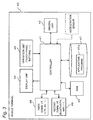
FIG. 4 is a diagram illustrating the configuration of thedata server 50. Thedata server 50 is realized by an information processing device such as a personal computer. Thedata server 50 includes acontroller 51 for controlling the overall operation, adisplay unit 53 for displaying a screen, anoperation unit 55 for the user to operate, and aRAM 56 and adata storage unit 57 for storing data and programs. Thedisplay unit 53 is realized by, for example, a liquid crystal display or an organic EL display. Theoperation unit 55 is realized by a keyboard, a mouse, a touch panel, and the like. - The
data server 50 further includes adevice interface 58 for connecting to an external device such as a printer and anetwork interface 59 for connecting to a network. Thedevice interface 58 is a communication module for performing data communication in accordance with USB, HDMI, IEEE 1394, or the like. Thenetwork interface 59 is a communication module that performs data communication in accordance with a standard such as IEEE 802.11 or Wi-Fi. - The
controller 51 includes a CPU or an MPU, and implements a predetermined function by executing apredetermined control program 57a stored in thedata storage unit 57. The control program executed by thecontroller 51 may be provided via thenetwork 200 or a recording medium such as a CD-ROM. - The
RAM 56 is a storage device for temporarily storing programs and data and functions as a work area of thecontroller 51. Thedata storage unit 57 is a recording medium that stores parameters, data, and programs necessary for implementing functions, and stores control programs executed by thecontroller 51 and various pieces of data. Thedata storage unit 51 is realized by, for example, a hard disk (HDD) or a semiconductor storage device (SSD). In thedata storage unit 57, thecontrol program 57a is installed for implementing functions described later. By executing thiscontrol program 57a, thecontroller 51 implements various functions described later. Thedata storage unit 57 also stores adatabase 57b relating to the driving behavior of the driver. Thedata storage unit 57 also functions as a working area of thecontroller 51. - The
database 57b manages data on the driving behavior in the vehicle in the following format, for example. Here, it manages a vehicle ID for identifying the vehicle, information indicating a measurement period (start date and end date) for the driving behavior, a safe driving rate, a dangerous driving rate, and a most dangerous driving rate. The safe driving rate indicates a ratio (percentage) of a period in which the driving is determined as safe driving in a measured driving period. The dangerous driving rate indicates a ratio (percentage) of a period in which the driving is determined as dangerous driving in the measured driving period. The most dangerous driving rate indicates a ratio (percentage) of a period in which the driving is determined as most dangerous driving in the measured driving period. Note that the data on the driving behavior managed in thedatabase 57b is not limited to the following data.[Table 1] Vehicle ID Measurement period (Start date, end date) Safe driving rate (%) Dangerous driving rate (%) Most dangerous driving rate (%) - The operation of the driving
behavior detection system 100 configured as described above is described below. -
FIG. 5 is a diagram for describing a transition of driving behavior data in the drivingbehavior detection system 100. In the driving behavior detection system, thetelemeter unit 10 calculates driving behavior data indicating the driving behavior of the driver based on the behavior data of the vehicle 30 (S1) and transmits the calculated data to themobile terminal 40 via the communication interface 18 (S2). Details of the operation of calculating the driving behavior data are described later. Themobile terminal 40 receives the driving behavior data from thetelemeter unit 10 via the second communication interface 49 (S2), and transmits the received driving behavior data to thedata server 50 via the first communication interface 48 (S3). Thedata server 50 receives the driving behavior data from the mobile terminal 40 (S3) and updates thedatabase 57b based on the received driving behavior data (S4). As described above, the driving behavior data detected by thetelemeter unit 10 is transmitted to thedata server 50, and thedatabase 57b is updated with the driving behavior data. By referring to thedatabase 57b, it is possible to recognize the vehicle driving behavior of the driver. - A driving behavior detection operation of the driving behavior detection system is described.
- It is generally known that there is a correlation between the acceleration during driving of the vehicle and the driving situation. For example, in normal town driving, a gentle acceleration in a car is at most about 0.15 G. When the acceleration exceeds 0.3 G, it can be determined as "rough driving".
-
FIG. 6 is a graph illustrating a change in vehicle speed measured when sudden braking is applied while the vehicle is descending a gentle slope. In this example, a minivan (with two people riding) descending a gentle slope is driven such that normal deceleration is performed from a speed of about 50 km/h, and when the speed reaches 20 km/h, sudden braking is applied for sharp deceleration to 0 km/h. For such driving of the vehicle, a change in acceleration of the vehicle was measured by an acceleration sensor (seeFIG. 7 described later). The measurement was carried out for about 11 seconds at a sampling interval of 20 ms. - In
FIG. 6 , the driving until sudden braking started when the speed of 20 km/h is reached (until time t1) is "safe driving", while the driving until the vehicle is stopped after the sudden braking (from time t1 to t2) is "most dangerous driving." -
FIG. 7 is a graph illustrating a change in acceleration measured by the acceleration sensor with respect to the behavior of the vehicle as shown inFIG. 6 . A plot X represents an acceleration in the X direction (the width direction of the vehicle), a plot Y represents an acceleration in the Y direction (the traveling (the forward and rearward) direction of the vehicle), and a plot Z represents an acceleration in the Z direction (the upward direction of the vehicle). As shown inFIG. 7 , when sudden braking is started at time t1, the acceleration in the Y direction (traveling direction) changes greatly. At this time, the vehicle gently descends the slope, and thus an offset of 0.3 always occurs in the acceleration in the Y direction. The magnitude of this offset varies depending on the inclination angle of the slope and the weight of the vehicle. As described above, since the offset occurs in the acceleration, it is difficult to accurately determine whether the state is the "safe driving state" or the "most dangerous driving state" only based on the acceleration. - Therefore, as a result of earnest research, the inventor has found that the driving behavior (i.e., the driving state) can be accurately detected by determining the driving behavior considering of the jerk in addition to the acceleration. Note that the jerk is an amount that indicates the rate of change in acceleration, obtained by differentiation of the acceleration.
-
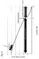
FIG. 8 is a graph plotting changes in acceleration and jerk measured in the Y-axis direction (traveling direction) with respect to the sampling points measured for the behavior of the vehicle shown inFIG. 6 , on a two-dimensional plane (hereinafter referred to as "J-G plane") In the J-G plane shown inFIG. 8 , a horizontal axis represents a jerk (J) and a vertical axis represents an acceleration (G). - The inventor has discovered that plots of the sampling points draw a unique locus on such a J-G plane due to a sudden change of the vehicle behavior. Specifically, in a situation where safe driving is being performed as shown in
FIGS. 6 and7 , plots concentrate in a range p (an area indicated by a dashed line) where the jerk (J) and the acceleration (G) are relatively small on the J-G plane as shown inFIG. 8 . Thereafter, when sudden braking is applied and the vehicle enters the most dangerous driving situation, a locus Q of the plots is drawn in the counterclockwise direction, greatly exceeding the range P on the J-G plane. - The inventor has found that the driving situation can be accurately grasped by considering such a locus Q of the plots on the J-G plane. Specifically, first, as shown in
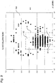
FIG. 9 , thresholds, that is, determination areas R1 to R3 are two-dimensionally set on the J-G plane. Then, the driving behavior data is calculated based on the number of plots included in the determination areas R1 to R3 set on the J-G plane. In the example ofFIG. 9 , an area R1 (an area indicated by a broken line A) where the acceleration is not larger than a first threshold (0.45) and the absolute value of the jerk is not larger than a second threshold (1.0) is set, as the determination area. Further, there is set an area R2 (an area indicated by a dashed line B) which is an area outside the area R1 and in which the acceleration is not larger than a third threshold (0.7 > first threshold) and the absolute value of the jerk is not larger than a fourth threshold (3.0 > second threshold) . Moreover, an area R3 is set outside the area R2. - The area R1 set as described above is an area where both the acceleration (G) and the jerk (J) are relatively small and is an area in which the driving is determined as "safe driving". The area R3 is an area where both the acceleration (G) and the jerk (J) are relatively large, and is an area in which the driving is determined as "most dangerous driving". The area R2 is an intermediate area between the area R1 and the area R3, and is an area in which the driving is determined as "dangerous driving".
- In calculating the driving behavior data of the present embodiment, the number of plots included in each of areas R1 to R3 is counted, and a ratio (percentage) of the count in each of areas R1 to R3 to a total number of plots is calculated. That is, as driving behavior data, the percentages of the periods of "safe driving", "dangerous driving", and "most dangerous driving" with respect to the whole operation period are calculated based on the counts of plots for areas R1, R2 and R3.
-
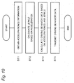
FIG. 10 is a flowchart showing a generation process for the driving behavior data. With reference toFIG. 10 , the generation process for the driving behavior data in thetelemeter unit 10 is described below. The process shown inFIG. 10 is mainly executed by thecontroller 11 of thetelemeter unit 10. - During the vehicle driving, the acceleration (G) of the
vehicle 30 is detected (measured) at a predetermined sampling interval (e.g., 20 msec) by theacceleration sensor 15 in thetelemeter unit 10, and information indicating the detected (measured) acceleration is accumulated in thememory 17. - When the process shown in
FIG. 10 is started, thecontroller 11 of thetelemeter unit 10 reads from thememory 17 the information of the acceleration (G) measured and stored in a predetermined period (e.g., one month) (S11). - The
controller 11 calculates the jerk (J) at the sampling point based on each read acceleration (G) in the Y direction (S12). Information on the acceleration and jerk at each sampling point is handled as "vehicle behavior data". - Next, the
controller 11 calculates the driving behavior data based on the behavior data indicating the jerk (J) and the acceleration (G) for each sampling point (S13). A method for calculating the driving behavior data will be detailed below. - First, the
controller 11 plots each piece of behavior data (information indicating the jerk and acceleration at each sampling point) on the J-G plane as shown inFIG. 9 . Thecontroller 11 counts the number of pieces of behavior data included in each of areas R1 to R3 on the J-G plane. Thecontroller 11 then calculates, as the driving behavior data, a ratio (percentage) of the count in each of areas R1 to R3 to a total number of pieces of behavior data (sampling points). Then, the safe driving rate is obtained based on the ratio (percentage) of the count for area R1 to the total count. The dangerous driving rate is obtained based on the ratio (percentage) of the count for the area R2 to the total count. The most dangerous driving rate is obtained based on the ratio (percentage) of the count for the area R3 to the total count. Instead of the ratio (percentage) of the count, the count for each of areas R1 to R3 may be used as the driving behavior data. - Thereafter, the
controller 11 of thetelemeter unit 10 transmits the obtained driving behavior data to themobile terminal 40 via the communication interface 18 (S14). - The
mobile terminal 40 receives the driving behavior data from thetelemeter unit 10 via thesecond communication interface 49 and transmits the received driving behavior data to thedata server 50 connected to thenetwork 200 via thefirst communication interface 48. Thedata server 50 receives the driving behavior data via thenetwork interface 59 and updates thedatabase 57b based on the received data (seeFIG. 5 ). -
FIG. 11 is a diagram for describing the significance of the driving behavior data obtained by the drivingbehavior detection system 100 of the present embodiment. This figure shows the driving behavior data obtained by the drivingbehavior detection system 100 for the behavior of the vehicle when sudden braking is applied while the vehicle is descending a gentle slope as shown inFIGS. 6 and7 . - The driving behavior data shown in the figure indicates that a ratio of safe driving (a ratio of the number of plots in the area R1 on the J-G plane) is 70%, a ratio of dangerous driving (a ratio of the number of plots in the area R2 on the J-G plane) is 22%, and a ratio of most dangerous driving (a ratio of the number of plots in the area R3 on the J-G plane) is 8%. For the examples of the driving shown in
FIGS. 6 and7 , the driving before occurrence of sudden braking is considered as safe driving, and the driving after occurrence of sudden braking is considered as most dangerous driving (including dangerous driving). In the examples ofFIGS. 6 and7 , the ratio of the period from the occurrence of sudden braking to the stop of the vehicle, namely the period of most dangerous driving (including dangerous driving) to the entire measurement period is 33%, and the ratio of the period of safe driving to the entire measurement period is 67%. As shown inFIG. 11 , for the driving behavior data obtained by the drivingbehavior detection system 100 of the present embodiment, the ratio of most dangerous driving (including dangerous driving) is 30% (= 22% + 8%), and it is found therefrom that a detection result close to an actual measurement value (33%) has been obtained. - As described above, the telemeter unit 10 (an example of the driving behavior detection device) according to the present embodiment includes: the acceleration sensor 15 (an example of an acquisition unit) that acquires a time series of an acceleration of a vehicle; and the
controller 11 that generates driving behavior data indicating a driving behavior of a driver of the vehicle based on a time series of behavior data indicating an acceleration (G) of the vehicle and a jerk (J) that is a change rate of the acceleration. Thecontroller 11 sets a J-G plane (an example of a determination plane) with coordinate axes for the acceleration and the jerk. Thecontroller 11 sets, as an area indicating safe driving on the J-G plane, the area R1 (an example of a first area) in which the acceleration is equal to or smaller than a first predetermined value and the jerk is equal to or smaller than a second predetermined value. Thecontroller 11 sets the areas R2 and R3 (an example of a second area) other than the area R1, as an area indicating non-safe driving. Thecontroller 11 generates driving behavior data based on the behavior data disposed in areas R1, R2, and R3. - As described above, the
telemeter unit 10 of the present embodiment detects the driving behavior of the driver based on the area of the determination plane with coordinate axes for the acceleration and the jerk. That is, consideration of the jerk in addition to the acceleration enables more accurate detection of the driving behavior without affection of the offset of the acceleration which is generated depending on the weight of the vehicle or the like. -
FIG. 12 is a diagram showing the configuration of a drivingbehavior detection system 100b in a second embodiment of the present disclosure. In the first embodiment, the drivingbehavior detection system 100 is composed of thetelemeter unit 10, themobile terminal 40, and thedata server 50. In contrast, the drivingbehavior detection system 100b of the present embodiment is composed of atelemeter unit 10 mounted on the vehicle and adata server 50. That is, thetelemeter unit 10 transmits data directly to thedata server 50 not through themobile terminal 40. Note that thetelemeter unit 10 can be connected to thenetwork 200 via thecommunication interface 18 so as to communicate with thedata server 50. -
FIG. 13 is a diagram for describing the transition of driving behavior data in the second embodiment. As shown in the figure, thetelemeter unit 10 calculates driving behavior data (S41) and transmits the calculated driving behavior data to the data server 50 (S42). Thedata server 50 updates thedatabase 57b based on the received data (S43). - The
telemeter unit 10 may transmit the driving behavior data to thedata server 50 every predetermined interval (e.g., one month). Alternatively, thetelemeter unit 10 may transmit data when instructed by the user, or when a predetermined operation (such as engine start) of the vehicle is performed. - In the present embodiment, a configuration in which the
mobile terminal 40 has the aforementioned functions of thetelemeter unit 10 is described. That is, in the first embodiment, although thetelemeter unit 10 detects the acceleration of thevehicle 30 and calculates the driving behavior data, themobile terminal 40 may execute these functions of thetelemeter unit 10. -
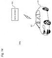
FIG. 14 is a diagram showing a configuration of a drivingbehavior detection system 100c in a third embodiment of the present disclosure. The drivingbehavior detection system 100c of the present embodiment is composed of amobile terminal 40 and adata server 50. Themobile terminal 40 of the present embodiment is provided with an acceleration sensor capable of detecting accelerations in three orthogonal directions (XYZ directions). Themobile terminal 40 is disposed in thevehicle 30 with the traveling direction (forward direction) of thevehicle 30 equal to the Y direction and the upward direction of the vehicle equal to the Z direction. Themobile terminal 40 disposed in thevehicle 30 as thus described periodically measures and records the acceleration of thevehicle 30 while thevehicle 30 is driving. -
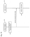
FIG. 15 is a diagram for describing a transition of driving behavior data in the third embodiment. As shown in the figure, themobile terminal 40 calculates driving behavior data based on the measured acceleration data in accordance with the method described above (S51) and transmits the calculated driving behavior data to the data server 50 (S52). Thedata server 50 updates thedatabase 57b based on the received driving behavior data (S53). - The
mobile terminal 40 may transmit the driving behavior data to thedata server 50 every predetermined period (e.g., one month), or may transmit data when predetermined operation (transmission instruction, etc.) is made by the user. - As described above, the first to third embodiments have been described as examples of the technique disclosed in the present application. However, the technique in the present disclosure is not limited to this, and can also be applied to embodiments in which changes, substitutions, additions, omissions, or the like are made appropriately. Further, it is also possible to combine the respective constituent elements described in the first to third embodiments to form a new embodiment. Therefore, another embodiment is exemplified below.
- In the first to third embodiments, the
telemeter unit 10 has been described as an example of the driving behavior detection device. The driving behavior detection device is not limited to thetelemeter unit 10. Themobile terminal 40 or thedata server 50 can also be configured as the driving behavior detection device. - For example, in the first embodiment, as shown in
FIG. 5 , the driving behavior data is calculated in thetelemeter unit 10. However, the driving behavior data may be calculated in a device other than thetelemeter unit 10, such as themobile terminal 40 or thedata server 50. - More specifically, when the driving behavior data is calculated in the
mobile terminal 40, thetelemeter unit 10 transmits time series of the data of the detected acceleration to themobile terminal 40. Themobile terminal 40 receives time series of the acceleration data via the second communication interface 49 (an example of the acquisition unit) and stores the received time series of the acceleration data into thedata storage unit 47 for work. Themobile terminal 40 calculates a jerk (J) based on the received acceleration data, calculates driving behavior data based on the behavior data indicating the acceleration (G) and the jerk (J) (see steps S12 and S13 inFIG. 10 ), and transmits the calculated data to thedata server 50. With such a configuration, themobile terminal 40 can operate as the driving behavior detection device. In this case, the jerk data may be calculated by thetelemeter unit 10, and themobile terminal 40 may acquire information indicating the acceleration and the jerk from thetelemeter unit 10. - Further, when the driving behavior data is calculated in the
data server 50, thetelemeter unit 10 transmits the acceleration data to themobile terminal 40. Themobile terminal 40 transfers the received acceleration data to thedata server 50. Thedata server 50 receives time series of the acceleration data via the network interface 59 (an example of the acquisition unit) and stores the received time series of the acceleration data into thedata storage unit 57 for work. Thedata server 50 calculates the jerk (J) based on the received acceleration data, calculates the driving behavior data based on the behavior data indicating the acceleration and the jerk (see steps S12 and S13 inFIG. 10 ), and updates thedatabase 57b with the calculated driving behavior data. With such a configuration, thedata server 50 can operate as a driving behavior detection device. In this case, the jerk data may be calculated by thetelemeter unit 10 or themobile terminal 40, and thedata server 50 may acquire information indicating the acceleration and the jerk from thetelemeter unit 10 or themobile terminal 40. - Further, in the second and third embodiments, the driving behavior data may be calculated in the
data server 50. In this case, thedata server 50 receives time series of the acceleration data from thetelemeter unit 10 or themobile terminal 40 via the network interface 59 (an example of the acquisition unit). The time series of the received acceleration data is stored in thedata storage unit 57 for work. Thedata server 50 calculates the jerk (J) based on the received acceleration data and calculates the driving behavior data based on the behavior data indicating the acceleration and the jerk (see steps S12, S13 inFIG. 10 ). With such a configuration, thedata server 50 can operate as the driving behavior detection device also in the second and third embodiments. In this case, the jerk data may be calculated by thetelemeter unit 10 or themobile terminal 40, and thedata server 50 may acquire information indicating the acceleration and the jerk from thetelemeter unit 10 or themobile terminal 40. - The above embodiments describe the examples in which the
controllers controllers controllers - As described above, each of the embodiments has been described as illustration of the technique in the present disclosure. To that end, the accompanying drawings and detailed description have been provided.
- Accordingly, some of the constituent elements described in the accompanying drawings and the detailed description can include not only constituent elements essential for solving the problem, but also constituent elements not being essential for solving the problem but provided for illustrating the above technique. For this reason, these nonessential constituent elements should not be recognized as essential as soon as these nonessential constituent elements are described in the accompanying drawings and detailed description.
- Further, since the above embodiments have been provided for illustrating the technique in the present disclosure, it is possible to make various changes, substitutions, additions, omissions, or the like within the scope of claims or the equivalent thereof.
- The present disclosure can be applied to a device for detecting a driving behavior of a driver of a vehicle.
Claims (7)
- A driving behavior detection device comprising:an acquisition unit configured to acquire information indicating an acceleration of a vehicle; anda computing unit configured to generate driving behavior data indicating a driving behavior of a driver of the vehicle based on time series of behavior data indicating an acceleration of the vehicle and a jerk that is a change rate of the acceleration, whereinthe computing unit
sets a determination plane with coordinate axes set for the acceleration and the jerk,
sets, on the determination plane, a first area in which the acceleration is equal to or smaller than a first predetermined value and the jerk is equal to or smaller than a second predetermined value, as an area indicating safe driving, and sets a second area other than the first area, as an area indicating non-safe driving, and
generates the driving behavior data based on the behavior data disposed in the first and second areas. - The driving behavior detection device according to claim 1, wherein the computing unit plots each piece of behavior data on the determination plane and generates the driving behavior data based on the number of pieces of behavior data included in each of the first and second areas.
- The driving behavior detection device according to claim 1, wherein
the acquisition unit is an acceleration sensor configured to measure an acceleration of the vehicle, and
the computing unit calculates a jerk based on the information indicating the acceleration measured by the acceleration sensor to generate the behavior data. - The driving behavior detection device according to claim 1, wherein
the acquisition unit is a communication interface configured to acquire information indicating the acceleration from an external device, and
the computing unit calculates a jerk based on the information indicating the acceleration acquired from the external device to generate the behavior data. - The driving behavior detection device according to claim 1, further comprising a communication unit configured to transmit the driving behavior data to outside.
- A driving behavior detection system comprising:the driving behavior detection device according to any one of claims 1 to 5;a mobile terminal configured to receive the driving behavior data from the driving behavior detection device and transfer the driving behavior data to an external device; anda server configured to receive the driving behavior data from the mobile terminal and store the driving behavior data into a storage unit.
- A driving behavior detection system comprising:the driving behavior detection device according to any one of claims 1 to 5; anda server configured to receive the driving behavior data from the driving behavior detection device and store the driving behavior data into a storage means.
Applications Claiming Priority (2)
| Application Number | Priority Date | Filing Date | Title |
|---|---|---|---|
| JP2015222467 | 2015-11-12 | ||
| PCT/JP2016/004753 WO2017081851A1 (en) | 2015-11-12 | 2016-10-28 | Driving improvement detection device and driving improvement detection system |
Publications (2)
| Publication Number | Publication Date |
|---|---|
| EP3360749A1 true EP3360749A1 (en) | 2018-08-15 |
| EP3360749A4 EP3360749A4 (en) | 2018-10-24 |
Family
ID=58695137
Family Applications (1)
| Application Number | Title | Priority Date | Filing Date |
|---|---|---|---|
| EP16863818.7A Withdrawn EP3360749A4 (en) | 2015-11-12 | 2016-10-28 | Driving improvement detection device and driving improvement detection system |
Country Status (3)
| Country | Link |
|---|---|
| EP (1) | EP3360749A4 (en) |
| JP (1) | JPWO2017081851A1 (en) |
| WO (1) | WO2017081851A1 (en) |
Family Cites Families (11)
| Publication number | Priority date | Publication date | Assignee | Title |
|---|---|---|---|---|
| DE4314826B4 (en) * | 1993-05-05 | 2005-12-29 | Dr.Ing.H.C. F. Porsche Ag | Method for determining the power reserve of vehicles |
| JP2006335277A (en) * | 2005-06-03 | 2006-12-14 | Nissan Motor Co Ltd | Driving state estimation device and driving state estimation method |
| JP2008298979A (en) * | 2007-05-30 | 2008-12-11 | Pioneer Electronic Corp | Evaluation device for driving skill and method for evaluating driving skill and program for evaluating driving skill |
| WO2009104255A1 (en) * | 2008-02-20 | 2009-08-27 | パイオニア株式会社 | Device, method and computer program for evaluating operation of vehicle |
| JP2009234442A (en) * | 2008-03-27 | 2009-10-15 | Equos Research Co Ltd | Driving operation support device |
| US8604920B2 (en) * | 2009-10-20 | 2013-12-10 | Cartasite, Inc. | Systems and methods for vehicle performance analysis and presentation |
| IT1398073B1 (en) * | 2010-02-19 | 2013-02-07 | Teleparking S R L | SYSTEM AND ESTIMATE METHOD OF THE DRIVING STYLE OF A MOTOR VEHICLE |
| US20110307188A1 (en) * | 2011-06-29 | 2011-12-15 | State Farm Insurance | Systems and methods for providing driver feedback using a handheld mobile device |
| HK1204132A1 (en) * | 2012-01-13 | 2015-11-06 | Pulse Function F6 Limited | Telematics system with 3d inertial sensors |
| JP2014081947A (en) * | 2013-12-04 | 2014-05-08 | Denso Corp | Information distribution device |
| LT3092160T (en) * | 2014-01-10 | 2022-03-25 | E-Novia S.R.L. | System and method for estimating the driving style of a vehicle |
-
2016
- 2016-10-28 WO PCT/JP2016/004753 patent/WO2017081851A1/en not_active Ceased
- 2016-10-28 EP EP16863818.7A patent/EP3360749A4/en not_active Withdrawn
- 2016-10-28 JP JP2017549977A patent/JPWO2017081851A1/en not_active Withdrawn
Also Published As
| Publication number | Publication date |
|---|---|
| WO2017081851A1 (en) | 2017-05-18 |
| EP3360749A4 (en) | 2018-10-24 |
| JPWO2017081851A1 (en) | 2018-09-27 |
Similar Documents
| Publication | Publication Date | Title |
|---|---|---|
| EP2899547B1 (en) | Method and apparatus for determining acceleration of vehicle | |
| JP6425630B2 (en) | Elevator car call system and portable information terminal | |
| US20160070966A1 (en) | Head-mounted display head pose and activity estimation | |
| US10130843B2 (en) | Electronic device, control program, control method, and system | |
| TW201510948A (en) | Method and system for detecting conditions of drivers, and electronic apparatus thereof | |
| US11137600B2 (en) | Display device, display control method, and display system | |
| US20180255879A1 (en) | Receiving feedback based on pressure sensor data and movement data | |
| JP6057605B2 (en) | Drive recorder | |
| JP7594627B2 (en) | Information processing device, information processing program, information processing system, and information processing method | |
| WO2015105007A1 (en) | Travel direction determination device, map matching device, travel direction determination method and program | |
| JP7438126B2 (en) | Information processing method and information processing system | |
| EP3360749A1 (en) | Driving improvement detection device and driving improvement detection system | |
| JP2018024340A (en) | Driving tendency determination device and driving tendency determination system | |
| WO2021016875A1 (en) | Aerial vehicle landing method, unmanned aerial vehicle, and computer-readable storage medium | |
| EP3176759A1 (en) | Vehicle terminal | |
| CN111625755B (en) | Data processing method, device, server, terminal and readable storage medium | |
| JP2016059729A (en) | Measuring apparatus, measuring method and measuring program | |
| JP6684863B2 (en) | High-place work estimation device, high-place work estimation method, and computer program | |
| CN114131657B (en) | Industrial robot track detection device | |
| WO2018116496A1 (en) | Accident detection apparatus and accident detection system | |
| US12133725B2 (en) | Gait analysis apparatus, gait analysis method, and computer-readable recording medium | |
| CN108710443B (en) | Displacement data generation method and control system | |
| JP2020165981A (en) | Information processing system, information processing device, program, and information processing method | |
| JP2014082648A (en) | Electronic apparatus, image correction method, and program | |
| US20240193806A1 (en) | Information processing system, information processing method, and information processing program |
Legal Events
| Date | Code | Title | Description |
|---|---|---|---|
| PUAI | Public reference made under article 153(3) epc to a published international application that has entered the european phase |
Free format text: ORIGINAL CODE: 0009012 |
|
| 17P | Request for examination filed |
Effective date: 20180509 |
|
| AK | Designated contracting states |
Kind code of ref document: A1 Designated state(s): AL AT BE BG CH CY CZ DE DK EE ES FI FR GB GR HR HU IE IS IT LI LT LU LV MC MK MT NL NO PL PT RO RS SE SI SK SM TR |
|
| AX | Request for extension of the european patent |
Extension state: BA ME |
|
| A4 | Supplementary search report drawn up and despatched |
Effective date: 20180920 |
|
| RIC1 | Information provided on ipc code assigned before grant |
Ipc: B60W 40/09 20120101AFI20180915BHEP Ipc: B60W 50/00 20060101ALI20180915BHEP Ipc: B60W 40/107 20120101ALI20180915BHEP Ipc: G08G 1/16 20060101ALI20180915BHEP |
|
| DAV | Request for validation of the european patent (deleted) | ||
| DAX | Request for extension of the european patent (deleted) | ||
| STAA | Information on the status of an ep patent application or granted ep patent |
Free format text: STATUS: THE APPLICATION HAS BEEN WITHDRAWN |
|
| 18W | Application withdrawn |
Effective date: 20190415 |