EP3360620A1 - Method and device for producing a corrugated package sheet for a structured package - Google Patents
Method and device for producing a corrugated package sheet for a structured package Download PDFInfo
- Publication number
- EP3360620A1 EP3360620A1 EP17020052.1A EP17020052A EP3360620A1 EP 3360620 A1 EP3360620 A1 EP 3360620A1 EP 17020052 A EP17020052 A EP 17020052A EP 3360620 A1 EP3360620 A1 EP 3360620A1
- Authority
- EP
- European Patent Office
- Prior art keywords
- bending edge
- machine direction
- bending
- packing sheet
- tool
- Prior art date
- Legal status (The legal status is an assumption and is not a legal conclusion. Google has not performed a legal analysis and makes no representation as to the accuracy of the status listed.)
- Withdrawn
Links
Images


Classifications
-
- B—PERFORMING OPERATIONS; TRANSPORTING
- B21—MECHANICAL METAL-WORKING WITHOUT ESSENTIALLY REMOVING MATERIAL; PUNCHING METAL
- B21D—WORKING OR PROCESSING OF SHEET METAL OR METAL TUBES, RODS OR PROFILES WITHOUT ESSENTIALLY REMOVING MATERIAL; PUNCHING METAL
- B21D13/00—Corrugating sheet metal, rods or profiles; Bending sheet metal, rods or profiles into wave form
- B21D13/02—Corrugating sheet metal, rods or profiles; Bending sheet metal, rods or profiles into wave form by pressing
-
- B—PERFORMING OPERATIONS; TRANSPORTING
- B21—MECHANICAL METAL-WORKING WITHOUT ESSENTIALLY REMOVING MATERIAL; PUNCHING METAL
- B21D—WORKING OR PROCESSING OF SHEET METAL OR METAL TUBES, RODS OR PROFILES WITHOUT ESSENTIALLY REMOVING MATERIAL; PUNCHING METAL
- B21D43/00—Feeding, positioning or storing devices combined with, or arranged in, or specially adapted for use in connection with, apparatus for working or processing sheet metal, metal tubes or metal profiles; Associations therewith of cutting devices
- B21D43/02—Advancing work in relation to the stroke of the die or tool
- B21D43/028—Tools travelling with material, e.g. flying punching machines
-
- B—PERFORMING OPERATIONS; TRANSPORTING
- B01—PHYSICAL OR CHEMICAL PROCESSES OR APPARATUS IN GENERAL
- B01J—CHEMICAL OR PHYSICAL PROCESSES, e.g. CATALYSIS OR COLLOID CHEMISTRY; THEIR RELEVANT APPARATUS
- B01J2219/00—Chemical, physical or physico-chemical processes in general; Their relevant apparatus
- B01J2219/32—Details relating to packing elements in the form of grids or built-up elements for forming a unit of module inside the apparatus for mass or heat transfer
- B01J2219/322—Basic shape of the elements
- B01J2219/32203—Sheets
- B01J2219/3221—Corrugated sheets
-
- B—PERFORMING OPERATIONS; TRANSPORTING
- B01—PHYSICAL OR CHEMICAL PROCESSES OR APPARATUS IN GENERAL
- B01J—CHEMICAL OR PHYSICAL PROCESSES, e.g. CATALYSIS OR COLLOID CHEMISTRY; THEIR RELEVANT APPARATUS
- B01J2219/00—Chemical, physical or physico-chemical processes in general; Their relevant apparatus
- B01J2219/32—Details relating to packing elements in the form of grids or built-up elements for forming a unit of module inside the apparatus for mass or heat transfer
- B01J2219/328—Manufacturing aspects
- B01J2219/3281—Pleating
-
- B—PERFORMING OPERATIONS; TRANSPORTING
- B01—PHYSICAL OR CHEMICAL PROCESSES OR APPARATUS IN GENERAL
- B01J—CHEMICAL OR PHYSICAL PROCESSES, e.g. CATALYSIS OR COLLOID CHEMISTRY; THEIR RELEVANT APPARATUS
- B01J2219/00—Chemical, physical or physico-chemical processes in general; Their relevant apparatus
- B01J2219/32—Details relating to packing elements in the form of grids or built-up elements for forming a unit of module inside the apparatus for mass or heat transfer
- B01J2219/328—Manufacturing aspects
- B01J2219/3282—Molding
-
- B—PERFORMING OPERATIONS; TRANSPORTING
- B01—PHYSICAL OR CHEMICAL PROCESSES OR APPARATUS IN GENERAL
- B01J—CHEMICAL OR PHYSICAL PROCESSES, e.g. CATALYSIS OR COLLOID CHEMISTRY; THEIR RELEVANT APPARATUS
- B01J2219/00—Chemical, physical or physico-chemical processes in general; Their relevant apparatus
- B01J2219/32—Details relating to packing elements in the form of grids or built-up elements for forming a unit of module inside the apparatus for mass or heat transfer
- B01J2219/328—Manufacturing aspects
- B01J2219/3284—Pressing
-
- B—PERFORMING OPERATIONS; TRANSPORTING
- B01—PHYSICAL OR CHEMICAL PROCESSES OR APPARATUS IN GENERAL
- B01J—CHEMICAL OR PHYSICAL PROCESSES, e.g. CATALYSIS OR COLLOID CHEMISTRY; THEIR RELEVANT APPARATUS
- B01J2219/00—Chemical, physical or physico-chemical processes in general; Their relevant apparatus
- B01J2219/32—Details relating to packing elements in the form of grids or built-up elements for forming a unit of module inside the apparatus for mass or heat transfer
- B01J2219/328—Manufacturing aspects
- B01J2219/3288—Punching
Definitions
- the invention relates to a method for producing a corrugated packing sheet for a structured packing of a mass transfer column and to an apparatus for producing such a packing sheet.
- Such a mass transfer column has a cylindrical container in which so-called packages are arranged.
- packages are arranged.
- Disordered packages are beds of defined shaped bodies such as rings, cylinders, calipers or the like.
- metal mesh or sheets are folded and / or wrapped so that there is an intensive steering of the vapor and the liquid and the associated intense contact of both.
- ordered packs several packs of discs are stacked on top of each other. The packing disks are each in turn constructed on a plurality of stacked corrugated packing sheets.
- the EP 0 739 846 A1 describes a device for producing an obliquely pleated metal strip.
- the device comprises a pair of parallel intermeshing toothed rollers.
- the EP 1 044 787 B1 shows a method for shaping strip-shaped films.
- the method uses intermeshing toothed rollers.
- the CN 203678982 U describes a device for producing a corrugated metal strip.
- the device comprises two mold halves, wherein an upper mold half for forming the metal strip is driven perpendicular to this.
- the object of the present invention is to provide an improved method and apparatus for producing a corrugated packing sheet for a structured packing of a mass transfer column.
- the packing plate is only slightly deformed at each stroke of the forming tool.
- the packing sheet is not so heavily mechanically loaded by the deformation in comparison to known methods in which the waves are formed in one step and it can be realized in the method higher throughput speeds.
- the undeformed packing sheet can be provided, for example, as a so-called coil.
- the undeformed packing sheet can be cut to length prior to forming or after forming.
- the machine direction is defined as a direction in which the packing sheet is conveyed by the forming tool. The transport can, however, optionally take place counter to the machine direction.
- the forming tool comprises a first mold half and a second mold half.
- each of the two mold halves has a first bending edge and a second bending edge. At least the first one Tool half on the first bending edge and the second bending edge.
- the first bending edge is not identical to the second bending edge. That is, the first bending edge and the second bending edge are two separate components.
- the bending edges are arranged linearly spaced from each other. That is, the bending edges are not circumferentially arranged on a bending roll or toothed roll.
- the second tool half has at least one first bending edge, which is arranged between the first bending edge and the second bending edge of the first tool half.
- the shaft is then formed between the opposite bending edges of the tool halves of the forming tool to the packing plate.
- the packing sheet is guided or held in a forming region of the forming tool during the forming process only with the help of the bending edges.
- the packing sheet is reshaped by means of a third bending edge to n-th bending edge of the forming tool until the shaft has a desired depth, wherein the packing sheet is transported in the machine direction before each forming.
- the first tool half of the forming tool has a first bending edge, a second bending edge spaced from the first bending edge in the machine direction, and a third bending edge spaced from the second bending edge in the machine direction.
- the number of bending edges is arbitrary.
- the second die half preferably has a first bending edge, a second bending edge spaced from the first bending edge in the machine direction, a third bending edge spaced from the second bending edge in the machine direction, and a fourth bending edge spaced from the third bending edge in the machine direction.
- the bending edges of the first mold half are arranged so that they are each arranged between two bending edges of the second mold half.
- the number of bending edges is arbitrary.
- the forming of the packing sheet and the transporting thereof are carried out until the shaft has the desired depth.
- the desired depth preferably several waves are formed simultaneously.
- the depth of the wave is defined as the distance between a wave crest and a wave trough of the wave or vice versa.
- a first mold half and a second mold half of the forming tool are moved in opposite directions and perpendicular to the machine direction for forming the packing sheet.
- the first tool half and the second tool half are moved toward each other toward the packing sheet. Due to the symmetrical operation of the first mold half and the second mold half to a plane of symmetry of the packing sheet, a center plane of the packing sheet is not displaced during processing. For this purpose, an excitation of a sheet metal oscillation perpendicular to the median plane of the packing sheet can be prevented. As a result, the throughput speed can be increased in the process.
- the first mold half and the second mold half are moved in the same direction and parallel to the machine direction for forming the packing sheet.
- the first tool half and the second tool half are moved in opposite directions and perpendicular to the machine direction as well as in the same direction and parallel to the machine direction.
- a rotational movement of the two tool halves By a rotational movement of the two tool halves, a part of a feed movement of the packing sheet can be realized.
- This also allows a higher throughput speed can be achieved.
- the movements of the first mold half and the second mold half interfere in opposite directions and perpendicular to the machine direction with the movements of the first mold half and the second mold half in the same direction and parallel to the machine direction. This can result in a cyclical movement of the tool halves.
- the packing sheet is transported in the machine direction by means of the movement of the first tool half and the second tool half parallel to the machine direction.
- the forming tool can thus also additionally be used as a transport device for the packing plate or referred to as a transport device become. This makes it possible to dispense with an additional transport device. This simplifies the process.
- the packing plate is braked by means of a braking device.
- a constant braking force can be applied to the packing plate.
- This can be done electrically by eddy currents or mechanically by brake pads.
- the braking force can be applied to the brake pads, for example with the aid of adjustable springs, weights, piezo actuators or pneumatic cylinders.
- the braking device may also be a regulated and controlled system.
- a control device can determine the optimum point in time and the strength of the braking process based on a crankshaft angle position of a device for producing the corrugated packing plate from data of a position sensor so that the packing plate assumes the optimum position for the next engagement of the forming tool.
- the brake can be done electrically by eddy currents or mechanically by brake pads.
- the brake pads can be driven by piezo actuators, hydraulic cylinders or electric cylinders.
- the packing sheet is deformed between opposed bending edges of the first tool half and bending edges of the second tool half.
- the bending edges of the first mold half and the bending edges of the second mold half are arranged so that each bending edge of the first mold half engages between two bending edges of the second mold half and vice versa.
- the packing sheet is transported by means of a transport device, in particular a non-contact transport device.
- the transport device can also be referred to as a feed device. With the help of the transport device, the packing plate in the machine direction be encouraged.
- the transport means may also be identical to the forming tool, namely when the tool halves of the forming tool are moved not only perpendicular to the machine direction but also parallel to the machine direction.
- the transport device can also be set up to transport the packing plate counter to the machine direction. As a result, an accurate positioning of the shaft to the bending edges is possible.
- the bending edges are moved according to this angle along a wave trough of the shaft.
- the first mold half and the second mold half are preferably formed so that the respective bending bars having the bending edges are not perpendicular to a side edge of the packing sheet but obliquely arranged at an angle thereto.
- the bending bars are therefore also arranged obliquely to the machine direction.
- the individual bending bars can be arranged to be laterally displaceably mounted in the respective tool half, in order to compensate for a lateral movement of the bending bars when the bending bars penetrate into the packing plate resulting from the oblique undulation.
- the apparatus comprises a forming tool comprising a first bending edge adapted to form a shaft on an undeformed packing sheet and a second bending edge spaced in a machine direction from the first bending edge and configured to deepen the shaft.
- the packing sheet can be transported by means of a transporting device.
- the transport device can be done for example by a roller or conveyor belt feed.
- the transport device may alternatively be identical to the forming tool.
- the packing sheet is transported in the machine direction by means of the forming tool. You can do this Tool halves of the forming tool are moved so that they perform both a movement perpendicular to the machine direction and a movement parallel to the machine direction. By means of the parallel movement of the tool halves, the packing sheet can be transported in the machine direction.
- the forming tool comprises a first mold half and a second mold half, which are movable in opposite directions and perpendicular to the machine direction for forming the packing sheet.
- the device preferably has a first tool carrier for the first tool half and a second tool carrier for the second tool half.
- the tool carriers are each mounted linearly displaceably in a first guide direction and in a second guide device.
- drive means the tool carriers are driven to move the first tool half and the second tool half perpendicular to the machine direction on the packing sheet to and from the packing sheet.
- the drive means are synchronized so that the first mold half and the second mold half move in opposite directions to or away from each other.
- a drive device may be provided for both tool carriers.
- the synchronization can be electrical, mechanical, for example via a gear or a belt drive, or hydraulically.
- the first mold half and the second mold half are movable in the same direction and parallel to the machine direction for forming the packing sheet.
- each bearing block is connected by means of its associated tool carrier using crankshafts.
- the crankshafts are rotatably mounted on respective eccentric axes of the bearing blocks and the tool carrier.
- the two provided on the tool carrier eccentric axes move during the forming of the packing sheet each on a circular path, whereby both the movement of the tool halves perpendicular to the machine direction and parallel to the machine direction is realized.
- each tool carrier four crankshafts and two bearing blocks are assigned, which are each positioned laterally from the tool carrier. At the bearing blocks each eccentric axes are provided, on which the crankshafts are mounted.
- eccentric axes are provided, on which the crankshafts are also mounted.
- the eccentric axes of the tool carriers move when opening and closing the forming tool each on a circular path.
- the movements of the first mold half and the second mold half interfere in opposite directions and perpendicular to the machine direction with the movements of the first mold half and the second mold half in the same direction and parallel to the machine direction. This can result in a cyclical movement of the tool halves.
- the device further comprises a transport device, in particular a non-contact transport device, which is adapted to transport the packing plate in the machine direction, so that the shaft from the first bending edge to the second bending edge is transportable.
- a transport device in particular a non-contact transport device, which is adapted to transport the packing plate in the machine direction, so that the shaft from the first bending edge to the second bending edge is transportable.
- the transport device can also be referred to as a feed device.
- the packing plate can be conveyed in the machine direction.
- the transport device can also be set up to transport the packing plate counter to the machine direction.
- the transport means may be a non-contact sheet feed which conveys the packing sheet by means of eddy currents in the machine direction.
- the forming tool has a third bending edge to nth bending edge, which are each arranged at a distance from each other in the machine direction.
- both the first mold half and the second mold half are each assigned a plurality of bending edges.
- each mold half has a plurality of bending bars, each bending bar comprising a bending edge.
- the bending bars can be arranged perpendicular to the machine direction.
- the Bending bars also be positioned obliquely to the machine direction, so that a skewed corrugation of the packing plate is possible.
- the individual bending bars can be arranged displaceably mounted laterally to compensate for a lateral movement in the penetration of the bending edges in the packing sheet, resulting from the oblique curvature.
- a respective distance between the first bending edge to the n-th bending edge in the machine direction decreases.
- a first distance between a first bending edge and a second bending edge of the first tool half is smaller than a second distance between the second bending edge and the third bending edge of the first tool half.
- a first distance between a first bending edge and a second bending edge of the second tool half is greater than a second distance between the second bending edge and the third bending edge of the second tool half.
- a third distance between the third bending edge and the fourth bending edge of the second tool half is smaller than the second distance. That is, for both tool halves, the distance between the bending edges in the machine direction is gradually reduced. But it can also be provided, in particular adjacent, bending edges, which are arranged uniformly spaced from each other.
- a respective distance, with which the first bending edge to the n-th bending edge extends into a forming region of the forming tool increases in the machine direction.
- the distance can also be referred to as depth.
- the forming area is preferably arranged symmetrically to a plane of symmetry of the packing sheet.
- the forming area is defined as an area where the bending edges of the first die half and the second die half penetrate when forming the package sheet.
- a third distance, with which the third bending edge of the first tool half extends into the forming area is greater than a second distance with which the second bending edge extends into the forming area, which in turn is larger than a first distance with which the second bending edge first bending edge of the first mold half in the forming area hineinerstreckt.
- the third distance of the third bending edge of the first tool half may correspond to the desired depth having the shaft.
- a fourth distance with which the fourth bending edge of the second tool half extends into the forming area is preferably greater than a third distance with which the third bending edge of the second mold half extends into the forming area, which in turn is in particular larger than a second distance with which the second bending edge of the second mold half extends into the forming area, which in turn is preferably larger than a first distance with which a first bending edge of the second mold half extends into the forming area. That is, the distances between the bending edges become smaller in the machine direction, whereas the intervals at which the bending edges penetrate into the forming area become larger in the machine direction. But it can also be provided, in particular adjacent, bending edges, which penetrate equally far into the forming area.
- the apparatus further comprises a braking device configured to stop the packing sheet in the machine direction so that the shaft is positionable at one of the bending edges.
- the braking device is adapted to stop the packing sheet so that the shaft is positioned above or below the corresponding bending edge.
- the packing plate can be positioned exactly, so that the shaft is positioned exactly at the desired bending edge.
- the shaft is stopped below or above the respective second bending edge.
- the braking device may be a braking device for applying a constant braking force. This can be done electrically by eddy currents or mechanically by brake pads. The braking force can be applied to the brake pads by adjustable springs, weights, piezo actuators or pneumatic cylinders.
- the braking device may also be a regulated and controlled system.
- the Fig. 1 shows a greatly simplified schematic sectional view of an embodiment of a mass transfer column 1.
- the mass transfer column 1 may be a rectification or air separation column.
- rectification is meant a thermal separation process which is an extension of the distillation or a series of many distillation steps.
- the advantages of the rectification that the mass transfer column 1 can be operated continuously and that the separation effect is many times higher compared to the distillation, since the vapor is in countercurrent contact with the liquid several times in contact.
- the mass transfer column 1 thus works energetically more favorably, technically less expensive and space-saving than a series connection of single distillations.
- the mass transfer column 1 comprises a container 2 which has a cylindrical geometry.
- the container 2 may for example be made of an aluminum material or a steel material.
- the container 2 is made of an aluminum material.
- the container 2 is cylindrically constructed around a symmetry or center axis M2.
- the container 2 may for example have a height of 30,000 to 50,000 millimeters.
- the container 2 may be a circular or approximately circular, for example, have an oval, cross-section.
- the container 2 is preferably constructed from a plurality of container sections or shell sections, which are connected to one another in a material-locking manner.
- the container sections may also be referred to as container sections, jacket sections or jacket sections.
- the center axis M2 is in the orientation of Fig. 1 vertically, that is, in a direction of gravity g.
- a plurality of stacked packages 3 is arranged, of which in the Fig. 1 however, only one is shown.
- the package 3 is a so-called ordered or structured package.
- ordered packs 3 as opposed to disordered packs, metal mesh or sheets of metal are folded and / or wrapped so that there is intensive steering of the vapor and liquid and associated intense contact of both.
- the package 3 can have a plurality of ordered or structured packing disks 4 to 8, which are arranged one above the other.
- the packing disks 4 to 8 may also be referred to as packing layers or packing layers.
- Such packing disks 4 to 8 consist of thin, corrugated and / or perforated metal plates or wire nets.
- the design of the packing disks 4 to 8 ensures an optimum exchange between the different phases (liquid / gaseous or liquid / liquid) with minimal pressure resistance.
- the number of packing disks 4 to 8 per pack 3 is arbitrary.
- the packing disks 4 to 8 can be made of vertically arranged packing sheets, in particular of corrugated aluminum sheets. Due to their structure, the packing disks 4 to 8 form condensation surfaces on which, for example, air components can condense during the air separation.
- the packing sheets used may have a thickness of 0.1 millimeter.
- Each packing disk 4 to 8 may, for example, have a thickness of 200 to 500 millimeters.
- the package 3 may thus have a height h3 of, for example, 1,000 to 7,000 millimeters.
- Between the container 2 and the pack 3rd or between the container 2 and each packing disc 4 to 8 can still be provided a circumferential packing collar or sealing collar 9.
- the sealing collar 9 is optional and thus dispensable.
- the Fig. 2 shows a schematic perspective view of a portion of an embodiment of a packing sheet 10, a plurality of which the packing disks 4 to 8 are each constructed.
- the packing plate 10 has a corrugated shape with wave crests 11 and troughs 12.
- the wave crests 11 and the wave troughs 12 are arranged so that in each case a wave crest 11 is arranged between two wave troughs 12 and a wave trough 12 between two wave crests 11.
- the wave crests 11 and the wave troughs 12 form shafts 13 of the packing sheet 10.
- the packing sheet 10 may have corrugations, perforations, holes and / or openings.
- the packing sheet 10 is preferably formed of an aluminum material and, as previously mentioned, may have a thickness of 0.1 millimeter.
- a plurality of such packing sheets 10 are stacked on each other.
- the wave peaks 11 and the troughs 12 extend at an angle ⁇ to the central axis M2.
- the angle ⁇ is for example 45 °.
- Adjacent packing sheets 10 may be arranged so that the wave crests 11 and the troughs 12, in particular at an angle of 90 °, intersect.
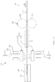
- the Fig. 3 to 5 each show a schematic view of an embodiment of an apparatus 14 for producing such a corrugated packing sheet 10 from an undeformed packing sheet 10 '.
- the device 14 comprises a forming tool 15 for this purpose. With the aid of the forming tool 15, the undeformed packing sheet 10 'can be formed into the corrugated packing sheet 10.
- the forming tool 15 comprises a lower or first mold half 16, which is arranged with respect to the direction of gravity g below the packing sheet 10 ', and an upper or second mold half 17, which is arranged with respect to the direction of gravity g above the packing sheet 10 '.
- the first mold half 16 comprises a first bending bar 18, a second bending bar 19 spaced apart from the first bending bar 18 in a machine direction M, and a third bending bar 20 spaced from the second bending bar 19 in the machine direction M.
- the number of bending bars 18 to 20 of FIG first mold half 16 is arbitrary. There may be more than three or less than three bending bars 18 to 20 are provided.
- the machine direction M is defined as a direction in which the packing sheet 10 'is transported by the forming tool 15.
- the second mold half 17 has a first bending bar 21 arranged upstream of the first bending bar 18 of the first mold half 16 with respect to the machine direction M, a second bending bar 22 spaced from the first bending bar 21 in the machine direction M, between the first bending bar 18 and the second bending bar 19 of the first mold half 16 is arranged, a spaced in the machine direction M from the second bending bar 22 arranged third bending bar 23 which is disposed between the second bending bar 19 and the third bending bar 20 of the first mold half 16, and one in the machine direction M spaced from the third bending bar 23 arranged fourth bending bar 24.
- the number of bending bars 21 to 24 of the second mold half 17 is arbitrary.
- the second tool half 17 may have more or less than four bending bars 21 to 24.
- one of the tool halves 16, 17 has at least one bending bar 18 to 24, and the other of the two tool halves 16, 17 has at least two such bending bars 18 to 24, which are arranged on both sides of a bending bar 18 to 24 of a mold half 16, 17 ,
- the apparatus 14 further comprises a first tool carrier 25, which carries the first tool half 16, and a second tool carrier 26, which carries the second tool half 17.
- the first tool carrier 25 is linearly guided on a first guide device 27, so that it can move perpendicular to the machine direction M on the packing sheet 10 'or move away from this, as in the Fig. 3 is shown by means of a double arrow 28.
- the device 14 further comprises a second guide means 29 in or on which the second tool carrier 26 is linearly guided so that it corresponds to the first tool carrier 25 can move perpendicular to the machine direction M on the packing sheet 10 'or move away from this, as in the Fig. 3 is shown by means of a double arrow 30.
- the device 14 furthermore has at least one drive device which is set up to drive the tool carriers 25, 26 in such a way that they move in opposite directions and synchronously on the packing plate 10 'or move away therefrom.
- each tool carrier 25, 26 may be assigned its own drive direction, wherein the drive means are synchronized with each other.
- the two tool carriers 25, 26 may have a common drive device.
- a guide device 31 is provided. With the help of the guide means 31, the packing sheet 10 'can be guided from above, from below and from both sides.
- the guide can be done by sliding surfaces or rollers.
- the guide device 31 is preceded by a transport device 32 with the aid of which the packing plate 10 'in the machine direction M can be conveyed through the forming tool 15.
- the transport device 32 can also be referred to as a feed device.
- the transport device 32 can be effected by a roller or conveyor belt feed.
- a driven roller 33, 34 or a conveyor belt is located above and below the packing sheet 10 '.
- the transport device 32 may also be a non-contact sheet feed, which conveys the packing sheet 10 'by means of eddy currents in the machine direction M.
- a controller that detects the position of the tool halves 16, 17 by means of a position sensor on the drive means, the transport device 32 control so that while the tool halves 16, 17 engage in the packing sheet 10 ', no force on the packing sheet 10' is exercised , so that the material required for a deformation of the packing sheet 10 'can be retightened by the movement of the tool halves 16, 17 itself.
- the packing sheet 10' is further transported by the transporting means 32 by a certain amount.
- the transport device 32 may also be configured to convey the package sheet 10 'counter to the machine direction M so that the package sheet 10' may be positioned relative to the tool halves 16, 17.
- a further guide device 35 Downstream of the forming tool 15 in the machine direction M, a further guide device 35 is provided.
- the corrugated packing sheet 10 is guided by means of the guide device 35 from above and from below.
- a lateral guide can be additionally provided.
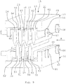
- the Fig. 6 shows a detailed view of the forming tool 15, wherein only the second mold half 17 is shown.
- the Fig. 7 shows a further detailed view of the forming tool 15.
- the second mold half 17 as the first mold half 16 comprises a base portion 36 from which the bending bars 21 to 24 in the direction of a plane of symmetry E10 of the packing sheet 10 'protrude.
- the first bending bar 21 is associated with a first bending edge 37 of the second mold half 17.
- the first bending bar 21 further comprises a base section 38 projecting out of the base section 36, which tapers over two side flanks 39, 40 towards the first bending edge 37.
- the side edges 39, 40 are inclined at an angle ⁇ to each other.
- the angle ⁇ can be between 0 ° and an angle ⁇ ( Fig. 7 ) be formed on the packing plate 10 shaft 13.
- the bending bars 22 to 24 are constructed analogously to the first bending bar 21 and thus each have a base section 38 and two side flanks 39, 40.
- the angles ⁇ of the bending bars 21 to 24 may differ from each other.
- the second bending bar 22 is associated with a second bending edge 41
- the third bending bar 23 is associated with a third bending edge 42
- the fourth bending bar 24 is associated with a fourth bending edge 43.
- the second bending edge 41 is arranged in the machine direction M by a first distance a1 from the first bending edge 37.
- the third bending edge 42 is spaced a second distance a2 from the second bending edge 41 in the machine direction M and the fourth bending edge 43 is spaced from the third bending edge 42 by a third distance a3.
- the second distance a2 is greater than the third distance a3 and the first distance a1 is greater than the second distance a2. That is, the distances a1 to a3 decrease in the machine direction M stepwise.
- the bending edges 37, 41 to 43 protrude differently far into a forming area UB of the forming tool 15.
- the forming area UB is arranged in bending symmetry with respect to the plane of symmetry E10.
- the first bending edge 37 projects beyond the plane of symmetry E10 by a first distance b1.
- the second bending edge 41 protrudes beyond the plane of symmetry E10 by a second distance b2, which is greater than the first distance b1.
- the third bending edge 42 projects beyond the plane of symmetry E10 by a third distance b3, which is greater than the second distance b2, and the fourth bending edge 43 projects beyond the plane of symmetry E10 by a fourth distance b4, which is greater than the third distance b3 out.
- the distances b1 to b4 increase stepwise in the machine direction M, whereas the distances a1 to a3 in the machine direction M gradually decrease.
- the tool halves 16, 17 can also have bending bars 18 to 24, in which, in particular adjacent, bending bars 18 to 24 have the same distances a1 to a3 or b1 to b4.
- the distances b1 to b4 can be adjusted for example by means of adjusting screws.
- the bending bars 18 to 20 of the first tool half 16 comprise a first bending edge 44 provided on the first bending bar 18, a second bending edge 45 provided on the second bending bar 19 and a third bending edge 46 on the third Bending strip 20 is provided.
- the bending edges 44, 46 are like the bending edges 37, 41 to 43 spaced apart in the machine direction M.
- the second bending edge 45 is disposed a first distance c1 from the first bending edge 44
- the third bending edge 46 is spaced from the second bending edge 45 by a second distance c2 which is smaller than the first distance c1.
- the distances c1, c2 between the bending edges 44 to 46 in the machine direction M reduce stepwise.
- the bending bars 18 to 20 of the first mold half 16 are otherwise constructed analogously to the bending bars 21 to 24 of the second mold half 17.
- the first bending edge 44 of the first tool half 16 is preferably centered, in particular with a slight offset in the direction of the second bending edge 41, disposed between the first bending edge 37 and the second bending edge 41 of the second mold half 17.
- the second bending edge 45 of the first mold half 16 is preferably arranged centrally, in particular with a slight offset in the direction of the third bending edge 42, between the second bending edge 41 and the third bending edge 42 of the second mold half 17 and the third bending edge 46 of the first mold half 16 is preferably positioned centrally between the third bending edge 42 and the fourth bending edge 43 of the second tool half 17.
- the bending edges 44 to 46 of the bending bars 18 to 20 protrude as the bending edges 37, 41 to 43 of the bending bars 21 to 24 to different degrees in the forming area UB.
- the first bending edge 44 protrudes beyond the plane of symmetry E10 by a first distance d1
- the second bending edge 45 projects beyond the plane of symmetry E10 by a second distance d2, which is greater than the first distance d1
- the third bending edge 46 projects around one third distance d3, which is greater than the second distance d2, beyond the plane of symmetry E10 addition. That is, the distances d1 to d3 are gradually increased in the machine direction M, whereas the distances c1, c2 in the machine direction M become progressively smaller as viewed.
- the distances d1 to d3 can be adjusted for example by means of adjusting screws.
- the Fig. 8 and 9 each show a detailed view of an embodiment of the forming tool 15.
- the bending bars 18 to 24 are designed as individual components.
- the first mold half 16 is a first Biegeleistenhalter 47 and the second mold half 17 is associated with a second Biegeleistenhalter 48.
- the first Biegeleistenhalter 47 the bending bars 18 to 20 are added.
- the second Biegeleistenhalter 48 the bending bars 21 to 24 are added.
- the distances c1, c2 in the machine direction M from each other can be adjusted by documents 49 to 52.
- the distances d1 to d3 are set by appropriate documents 53 to 55.
- the distances a1 to a3 can be adjusted by appropriate documents 56 to 60. Accordingly, the distances b1 to b4 can be adjusted by appropriate pad 61 to 64.
- the bending bars 18 to 20 and the documents 49 to 55 are connected by two screws 65, 66 with the first Biegeleistenhalter 47.
- the bending bars 21 to 24 and the documents 56 to 64 are correspondingly connected by screws 67, 68 with the second Biegeleistenhalter 48.
- the undeformed packing sheet 10 ' can be formed into the corrugated packing sheet 10.
- a shaft 13' with a wave crest 11 'and a wave trough 12' As a result, as in the Fig. 7 shown, formed on the first still undeformed packing sheet 10 'with the aid of the respective first bending edge 37, 44, a shaft 13' with a wave crest 11 'and a wave trough 12'.
- the shaft 13 ' after forming by means of the respective first bending edge 37, 44, has a depth which does not yet correspond to a desired depth t13 of the finished shaft 13.
- the depth t13 is defined as a distance between a wave crest 11 and a corrugation 12 or vice versa of the corrugated packing sheet 10.
- the forming tool 15 is opened again, wherein the first mold half 16 and the second mold half 17 perpendicular to the machine direction M of the packing sheet 10th 'be driven away, as in the Fig. 4 with the aid of arrows 71, 72 is shown.
- the packing sheet 10 ' is transported by means of the transport device 32 in the machine direction M so far that the shaft 13' comes to rest in front of the respective second bending edge 41, 45 of the forming tool 15.
- the forming tool 15 is then, as in the Fig. 3 and 5 shown, closed again, wherein the shaft 13 'with the second bending edges 41, 45 to a shaft 13 "with a wave crest 11" and a wave trough 12 "is recessed.
- the forming tool 15 is opened again, and the packing sheet 10 'is again transported in the machine direction M until the shaft 13 "comes to rest in front of the respective third bending edge 42, 46 of the second mold half 17.
- the forming tool 15 is closed again the shaft 13 "is converted to the finished shaft 13.
- the shaft 13 is deformed so that the desired depth t13 is reached, and the shaft 13 takes on its final shape from the bending edges 42, 43, 46.
- the corrugated packing sheet 10 can be cut to length.
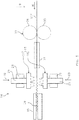
- the Fig. 10 and 11 show a further embodiment of a device 14 for producing a corrugated packing sheet 10.
- the embodiment of the device 14 differs from the embodiment of the device 14 according to the Fig. 3 to 7 in that the tool halves 16, 17 of the forming tool 15 are moved not only translationally perpendicular to the machine direction M but also parallel to the machine direction M.
- the device 14 comprises two eccentric shafts 73, 74 arranged on the first tool carrier 25, on which crankshafts 75, 76 are rotatably mounted.
- eccentric axles 80, 81 are provided on the second tool carrier 26, on which crankshafts 82, 82 ', 83, 83' are rotatably mounted.
- the device 14 also comprises a position sensor 87 and a braking device 88 for braking the packing plate 10 '.
- crankshafts 75, 76, 82, 82 ', 83, 83' are the eccentric axes 73, 74, 80, 81 about the eccentric axes 78, 79, 85, 85 ', 86, 86' on a circular path with a radius r25 or r26 moves.
- Drive means 89, 90 of the device 14 are coupled together rotationally synchronously.
- the tool carriers 25, 26 with the respective mold half 16, 17 make a circular movement with the radius r25, r26, but the respective tool carrier 25, 26 is always guided parallel to the machine direction M with the corresponding mold half 16, 17.
- the drive means, not shown, of the first tool half 16 and the drive means 89, 90 of the second tool half 17 are coupled together so that a vertical movement of the tool halves 16, 17, as shown by means of the double file 28, 30, symmetrical to the plane of symmetry E10 of the undeformed Packing plate is 10 '.
- the coupling of Drive means 89, 90 can be electrically, mechanically, for example by means of a control element or a transmission or hydraulically.
- the packing sheet 10 After the loss of contact with the forming tool 15, the packing sheet 10 'moves according to the inertia of the mass initially still at the original speed. Under optimal conditions, the movement of the packing sheet 10 'is such that no additional advancing or braking action is required.
- the forming tool 15 itself is a transporting device.
- the additional transport device 32 may be provided.
- the transport device 32 can take place by a roller or conveyor belt feed, wherein the driven rollers 33, 34 or a conveyor belt are located above and below the packing plate 10 '.
- the packing sheet 10' is further conveyed back by the transporting means 32 by the required amount. This amount can be constant.
- the position of the packing sheet 10 ' can always be monitored and, individually after each stroke, the position of the packing sheet 10' can be readjusted by the transport device 32.
- the braking device 88 may be a braking device for applying a constant braking force. This can be done electrically by eddy currents or mechanically by brake pads. The braking force can be applied to the brake pads by adjustable springs, weights, piezo actuators or pneumatic cylinders. The braking device 88 may also be a regulated and controlled system. Based on the crankshaft angle position from the position sensor system 87, the controller calculates the optimum point in time and the strength of the braking process so that the packing plate 10 'assumes the optimum position for the next tool engagement. Again, the brake can be done electrically by eddy currents or mechanically by brake pads. The brake pads can be driven by piezo actuators, hydraulic cylinders or electric cylinders.
- the packing sheet 10 ' Due to the multi-stage forming tool 15, the packing sheet 10 'is only slightly deformed at each stroke. As a result, the packing sheet 10 'is not overstressed by the deformation and higher throughput speeds can be realized. Due to the symmetrical operation of the first mold half 16 and the second mold half 17 to the plane of symmetry E10, a median plane of the packing sheet 10 'is not displaced during processing. As a result, there is no excitation of a sheet metal vibration perpendicular to the sheet plane. This is advantageous for high throughput speeds. During sheet metal forming a part of the feed motion is realized in the rotary process. This also increases the throughput speed.
- the Fig. 12 shows a further embodiment of a device 14 for manufacturing the corrugated packing sheet 10.
- the device according to the Fig. 12 differs from the device according to the Fig. 3 to 7 in that the tool halves 16, 17 are each effected by a crankshaft 93, 94 and a connecting rod 95, 96 coupled to both the respective crankshaft 93, 94 and the tool carrier 25, 26.
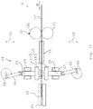
- the Fig. 13 shows a further embodiment of a device 14 for producing the corrugated packing sheet 10.
- the first mold half 16 and the second mold half 17 are formed so that the respective bending bars 18 to 24 are not perpendicular to a side edge 97 of Packungsblechs 10 ', but obliquely arranged at an angle ⁇ to this.
- the bending bars 18 to 24 are thus also arranged obliquely to the machine direction M.
- the individual bending bars 18 to 24 can, as shown with the aid of a double arrow 98, be arranged to be laterally displaceable in order to permit lateral movement of the bending bars 18 to 24 when the bending bars 18 to 24 penetrate into the packing sheet 10 'resulting from an oblique curvature results, to compensate.
- the Fig. 14 1 shows a schematic block diagram of an embodiment of a method for producing the corrugated packing sheet 10.
- the undeformed packing sheet 10 ' is provided in a step S1.
- the undeformed packing sheet 10 ' may be provided as a so-called coil.
- the packing sheet 10 ' is reshaped by means of the first bending edge 37, 44 of the forming tool 15 in order to form the shaft 13' on the packing sheet 10 '.
- a step S3 the packing sheet 10 'is transported in the machine direction M.
- the transporting device 32 or the forming tool 15 itself can be used for this purpose.
- the packing sheet 10 ' is reshaped using the second bending edge 41, 45 spaced from the first bending edge 37, 44 in the machine direction M in order to deepen the shaft 13' .
- the packing sheet 10 'can then be so often reshaped with the third bending edge 42, 46 to fourth, in particular n-th, bending edge 43 of the forming tool 15 until the shaft 13 has the desired depth t13.
- the packing sheet 10 ' is transported in each case in the machine direction M before each forming.
Landscapes
- Engineering & Computer Science (AREA)
- Mechanical Engineering (AREA)
- Containers And Plastic Fillers For Packaging (AREA)
Abstract
Ein Verfahren zum Herstellen eines gewellten Packungsblechs (10) für eine strukturierte Packung (3) einer Stoffaustauschkolonne (1), mit folgenden Schritten:
a) Bereitstellen (S1) eines unverformten Packungsblechs (10'), b) Umformen (S2) des Packungsblechs (10') mit Hilfe einer ersten Biegekante (37, 44) eines Umformwerkzeugs (15), um an dem Packungsblech (10') eine Welle (13') anzuformen, c) Transport (S3) des Packungsblechs (10') in einer Maschinenrichtung (M), und
d) Erneutes Umformen (S4) des Packungsblechs (10') mit Hilfe einer in der Maschinenrichtung (M) von der ersten Biegekante (37, 44) beabstandet angeordneten zweiten Biegekante (41, 45) des Umformwerkzeugs (15), um die Welle (13') zu vertiefen.

a) providing (S1) an undeformed packing sheet (10 '), b) reshaping (S2) the packing sheet (10') by means of a first bending edge (37, 44) of a forming tool (15) to engage the packing sheet (10 ') to form a shaft (13 '), c) transport (S3) of the packing sheet (10') in a machine direction (M), and
d) reshaping (S4) the packing sheet (10 ') by means of a second bending edge (41, 45) of the forming tool (15) spaced from the first bending edge (37, 44) in the machine direction (M) (FIG. 13 ') to deepen.
Description
Die Erfindung betrifft ein Verfahren zum Herstellen eines gewellten Packungsblechs für eine strukturierte Packung einer Stoffaustauschkolonne und eine Vorrichtung zum Herstellen eines derartigen Packungsblechs.The invention relates to a method for producing a corrugated packing sheet for a structured packing of a mass transfer column and to an apparatus for producing such a packing sheet.
Mit Hilfe von Stoffaustauschkolonnen, wie Rektifikations- oder Luftzerlegungssäulen, ist es möglich, verflüssigte Luft in ihre Bestandteile zu zerlegen. Eine derartige Stoffaustauschkolonne weist einen zylinderförmigen Behälter auf, in dem sogenannte Packungen angeordnet sind. Hierbei wird zwischen ungeordneten und geordneten Packungen unterschieden. Ungeordnete Packungen sind Schüttungen aus definiert geformten Körpern, wie Ringen, Zylindern, Sattelkörpern oder dergleichen. Im Gegensatz hierzu werden bei geordneten Packungen Metallgewebe oder-bleche so gefaltet und/oder gewickelt, dass es zu einer intensiven Lenkung des Dampfes und der Flüssigkeit und damit verbundenem intensiven Kontakt beider kommt. Bei geordneten Packungen werden mehrere Packungsscheiben aufeinandergestapelt. Die Packungsscheiben sind jeweils wiederum auf einer Vielzahl an aufeinandergestapelten gewellten Packungsblechen aufgebaut.By means of mass transfer columns, such as rectification or air separation columns, it is possible to decompose liquefied air into their constituents. Such a mass transfer column has a cylindrical container in which so-called packages are arranged. Here, a distinction is made between disordered and ordered packs. Disordered packages are beds of defined shaped bodies such as rings, cylinders, calipers or the like. In contrast, in orderly packs, metal mesh or sheets are folded and / or wrapped so that there is an intensive steering of the vapor and the liquid and the associated intense contact of both. In ordered packs, several packs of discs are stacked on top of each other. The packing disks are each in turn constructed on a plurality of stacked corrugated packing sheets.
Die
Die
Die
Die Aufgabe der vorliegenden Erfindung besteht darin, ein verbessertes Verfahren und eine verbesserte Vorrichtung zum Herstellen eines gewellten Packungsblechs für eine strukturierte Packung einer Stoffaustauschkolonne zur Verfügung zu stellen.The object of the present invention is to provide an improved method and apparatus for producing a corrugated packing sheet for a structured packing of a mass transfer column.
Demgemäß wird ein Verfahren zum Herstellen eines gewellten Packungsblechs für eine strukturierte Packung einer Stoffaustauschkolonne vorgeschlagen. Das Verfahren weist folgende Schritte auf:
- a) Bereitstellen eines unverformten Packungsblechs, b) Umformen des Packungsblechs mit Hilfe einer ersten Biegekante eines Umformwerkzeugs, um an dem Packungsblech eine Welle anzuformen, c) Transport des Packungsblechs in einer Maschinenrichtung, und d) erneutes Umformen des Packungsblechs mit Hilfe einer in der Maschinenrichtung von der ersten Biegekante beabstandet angeordneten zweiten Biegekante des Umformwerkzeugs, um die Welle zu vertiefen.
- a) providing an undeformed package sheet, b) forming the package sheet using a first bending edge of a forming tool to form a shaft on the package sheet, c) transporting the package sheet in a machine direction, and d) re-forming the package sheet by means of one in the machine direction spaced from the first bending edge arranged second bending edge of the forming tool to deepen the shaft.
Dadurch, dass die Welle mehrstufig oder schrittweise angeformt wird, wird das Packungsblech bei jedem Hub des Umformwerkzeugs nur gering verformt. Hierdurch ist das Packungsblech durch die Umformung im Vergleich zu bekannten Verfahren, bei denen die Wellen in einem Schritt angeformt werden, nicht so stark mechanisch belastet und es können bei dem Verfahren höhere Durchsatzgeschwindigkeiten realisiert werden.The fact that the shaft is formed in several stages or stepwise, the packing plate is only slightly deformed at each stroke of the forming tool. As a result, the packing sheet is not so heavily mechanically loaded by the deformation in comparison to known methods in which the waves are formed in one step and it can be realized in the method higher throughput speeds.
Darunter, dass die Welle vertieft wird, ist zu verstehen, dass eine Tiefe der Welle, die als ein Abstand zwischen einem Wellental und einem Wellenberg der Welle definiert ist, schrittweise vergrößert wird. Das unverformte Packungsblech kann beispielsweise als sogenanntes Coil bereitgestellt werden. Zum Herstellen des gewellten Packungsblechs kann das unverformte Packungsblech vor dem Umformen oder nach dem Umformen abgelängt werden. Die Maschinenrichtung ist definiert als eine Richtung, in der das Packungsblech durch das Umformwerkzeug gefördert wird. Der Transport kann allerdings optional auch entgegen der Maschinenrichtung erfolgen. Vorzugsweise umfasst das Umformwerkzeug eine erste Werkzeughälfte und eine zweite Werkzeughälfte.Under the fact that the wave is recessed, it is understood that a depth of the wave, which is defined as a distance between a wave trough and a wave crest of the wave, is gradually increased. The undeformed packing sheet can be provided, for example, as a so-called coil. To produce the corrugated packing sheet, the undeformed packing sheet can be cut to length prior to forming or after forming. The machine direction is defined as a direction in which the packing sheet is conveyed by the forming tool. The transport can, however, optionally take place counter to the machine direction. Preferably, the forming tool comprises a first mold half and a second mold half.
Mit Hilfe des Verfahrens wird kontinuierlich eine beliebige Anzahl an Wellen an das Packungsblech angeformt. Bevorzugt weist jede der beiden Werkzeughälften eine erste Biegekante und eine zweite Biegekante auf. Zumindest weist die erste Werkzeughälfte die erste Biegekante und die zweite Biegekante auf. Die erste Biegekante ist nicht identisch mit der zweiten Biegekante. Das heißt, die erste Biegekante und die zweite Biegekante sind zwei voneinander getrennte Bauteile. Insbesondere sind die Biegekanten linear voneinander beabstandet angeordnet. Das heißt, die Biegekanten sind nicht umfänglich auf einer Biegewalze oder Zahnwalze angeordnet. Die zweite Werkzeughälfte weist zumindest eine erste Biegekante auf, die zwischen der ersten Biegekante und der zweiten Biegekante der ersten Werkzeughälfte angeordnet ist. Die Welle wird dann zwischen den einander gegenüberliegenden Biegekanten der Werkzeughälften des Umformwerkzeugs an das Packungsblech angeformt. Das Packungsblech wird in einem Umformbereich des Umformwerkzeugs während des Umformprozesses nur mit Hilfe der Biegekanten geführt beziehungsweise gehalten.With the help of the method, any number of waves is continuously formed on the packing plate. Preferably, each of the two mold halves has a first bending edge and a second bending edge. At least the first one Tool half on the first bending edge and the second bending edge. The first bending edge is not identical to the second bending edge. That is, the first bending edge and the second bending edge are two separate components. In particular, the bending edges are arranged linearly spaced from each other. That is, the bending edges are not circumferentially arranged on a bending roll or toothed roll. The second tool half has at least one first bending edge, which is arranged between the first bending edge and the second bending edge of the first tool half. The shaft is then formed between the opposite bending edges of the tool halves of the forming tool to the packing plate. The packing sheet is guided or held in a forming region of the forming tool during the forming process only with the help of the bending edges.
Gemäß einer Ausführungsform wird das Packungsblech nach dem Schritt d) mit Hilfe einer dritten Biegekante bis n-ten Biegekante des Umformwerkzeugs so oft umgeformt, bis die Welle eine gewünschte Tiefe aufweist, wobei das Packungsblech vor jedem Umformen jeweils in der Maschinenrichtung transportiert wird.According to one embodiment, after the step d), the packing sheet is reshaped by means of a third bending edge to n-th bending edge of the forming tool until the shaft has a desired depth, wherein the packing sheet is transported in the machine direction before each forming.
Beispielsweise weist die erste Werkzeughälfte des Umformwerkzeugs eine erste Biegekante, eine in der Maschinenrichtung beabstandet von der ersten Biegekante angeordnete zweite Biegekante sowie eine in der Maschinenrichtung von der zweiten Biegekante beabstandet angeordnete dritte Biegekante auf. Die Anzahl der Biegekanten ist beliebig. Dementsprechend weist die zweite Werkzeughälfte vorzugsweise eine erste Biegekante, eine in der Maschinenrichtung beabstandet von der ersten Biegekante angeordnete zweite Biegekante, eine in der Maschinenrichtung von der zweiten Biegekante beabstandet angeordnete dritte Biegekante sowie eine in der Maschinenrichtung von der dritten Biegekante beabstandet angeordnete vierte Biegekante auf. Die Biegekanten der ersten Werkzeughälfte sind dabei so angeordnet, dass diese jeweils zwischen zwei Biegekanten der zweiten Werkzeughälfte angeordnet sind. Die Anzahl der Biegekanten ist beliebig. Das Umformen des Packungsblechs und das Transportieren desselben werden solange durchgeführt, bis die Welle die gewünschte Tiefe aufweist. Dabei werden bevorzugt mehrere Wellen gleichzeitig angeformt. Die Tiefe der Welle ist definiert als der Abstand zwischen einem Wellenberg und einem Wellental der Welle oder umgekehrt.For example, the first tool half of the forming tool has a first bending edge, a second bending edge spaced from the first bending edge in the machine direction, and a third bending edge spaced from the second bending edge in the machine direction. The number of bending edges is arbitrary. Accordingly, the second die half preferably has a first bending edge, a second bending edge spaced from the first bending edge in the machine direction, a third bending edge spaced from the second bending edge in the machine direction, and a fourth bending edge spaced from the third bending edge in the machine direction. The bending edges of the first mold half are arranged so that they are each arranged between two bending edges of the second mold half. The number of bending edges is arbitrary. The forming of the packing sheet and the transporting thereof are carried out until the shaft has the desired depth. In this case, preferably several waves are formed simultaneously. The depth of the wave is defined as the distance between a wave crest and a wave trough of the wave or vice versa.
Gemäß einer weiteren Ausführungsform werden zum Umformen des Packungsblechs eine erste Werkzeughälfte und eine zweite Werkzeughälfte des Umformwerkzeugs gegensinnig und senkrecht zu der Maschinenrichtung bewegt.According to a further embodiment, a first mold half and a second mold half of the forming tool are moved in opposite directions and perpendicular to the machine direction for forming the packing sheet.
Das heißt, zum Umformen des Packungsblechs werden die erste Werkzeughälfte und die zweite Werkzeughälfte aufeinander zu in Richtung auf das Packungsblech hin bewegt. Durch die symmetrische Arbeitsweise der ersten Werkzeughälfte und der zweiten Werkzeughälfte zu einer Symmetrieebene des Packungsblechs wird eine Mittelebene des Packungsblechs während der Bearbeitung nicht verschoben. Hierzu kann eine Anregung einer Blechschwingung senkrecht zu der Mittelebene des Packungsblechs verhindert werden. Hierdurch kann die Durchsatzgeschwindigkeit bei dem Verfahren erhöht werden.That is, for forming the packing sheet, the first tool half and the second tool half are moved toward each other toward the packing sheet. Due to the symmetrical operation of the first mold half and the second mold half to a plane of symmetry of the packing sheet, a center plane of the packing sheet is not displaced during processing. For this purpose, an excitation of a sheet metal oscillation perpendicular to the median plane of the packing sheet can be prevented. As a result, the throughput speed can be increased in the process.
Gemäß einer weiteren Ausführungsform werden zum Umformen des Packungsblechs die erste Werkzeughälfte und die zweite Werkzeughälfte gleichsinnig und parallel zu der Maschinenrichtung bewegt.According to a further embodiment, the first mold half and the second mold half are moved in the same direction and parallel to the machine direction for forming the packing sheet.
Vorzugsweise werden die erste Werkzeughälfte und die zweite Werkzeughälfte sowohl gegensinnig und senkrecht zu der Maschinenrichtung als auch gleichsinnig und parallel zu der Maschinenrichtung bewegt. Durch eine rotatorische Bewegung der beiden Werkzeughälften kann ein Teil einer Vorschubbewegung des Packungsblechs realisiert werden. Auch hierdurch kann eine höhere Durchsatzgeschwindigkeit erzielt werden. Insbesondere überlagern sich die Bewegungen der ersten Werkzeughälfte und der zweiten Werkzeughälfte gegensinnig und senkrecht zu der Maschinenrichtung mit den Bewegungen der ersten Werkzeughälfte und der zweiten Werkzeughälfte gleichsinnig und parallel zu der Maschinenrichtung. Hieraus kann eine zyklische Bewegung der Werkzeughälften resultieren.Preferably, the first tool half and the second tool half are moved in opposite directions and perpendicular to the machine direction as well as in the same direction and parallel to the machine direction. By a rotational movement of the two tool halves, a part of a feed movement of the packing sheet can be realized. This also allows a higher throughput speed can be achieved. In particular, the movements of the first mold half and the second mold half interfere in opposite directions and perpendicular to the machine direction with the movements of the first mold half and the second mold half in the same direction and parallel to the machine direction. This can result in a cyclical movement of the tool halves.
Gemäß einer weiteren Ausführungsform wird das Packungsblech mit Hilfe der zu der Maschinenrichtung parallelen Bewegung der ersten Werkzeughälfte und der zweiten Werkzeughälfte in der Maschinenrichtung transportiert.According to a further embodiment, the packing sheet is transported in the machine direction by means of the movement of the first tool half and the second tool half parallel to the machine direction.
Das Umformwerkzeug kann somit auch zusätzlich noch als Transporteinrichtung für das Packungsblech eingesetzt werden oder als Transporteinrichtung bezeichnet werden. Hierdurch kann auf eine zusätzliche Transporteinrichtung verzichtet werden. Hierdurch wird das Verfahren vereinfacht.The forming tool can thus also additionally be used as a transport device for the packing plate or referred to as a transport device become. This makes it possible to dispense with an additional transport device. This simplifies the process.
Gemäß einer weiteren Ausführungsform wird das Packungsblech mit Hilfe einer Bremseinrichtung abgebremst.According to a further embodiment, the packing plate is braked by means of a braking device.
Mit Hilfe der Bremseinrichtung kann beispielsweise eine konstante Bremskraft auf das Packungsblech aufgebracht werden. Dies kann elektrisch durch Wirbelströme oder mechanisch durch Bremsklötze erfolgen. Die Bremskraft kann auf die Bremsklötze beispielsweise mit Hilfe einstellbarer Federn, Gewichte, Piezoaktoren oder Druckluftzylinder aufgebracht werden. Die Bremseinrichtung kann auch ein geregeltes und gesteuertes System sein. Eine Steuereinrichtung kann dabei anhand einer Kurbelwellenwinkellage einer Vorrichtung zum Herstellen des gewellten Packungsblechs aus Daten einer Lagesensorik den optimalen Zeitpunkt und die Stärke des Bremsvorgangs ermitteln, so dass das Packungsblech für den nächsten Eingriff des Umformwerkzeugs die optimale Position einnimmt. Auch hier kann die Bremse elektrisch durch Wirbelströme oder mechanisch durch Bremsklötze erfolgen. Die Bremsklötze können durch Piezoaktoren, Hydraulikzylinder oder Elektrozylinder angetrieben werden.With the help of the braking device, for example, a constant braking force can be applied to the packing plate. This can be done electrically by eddy currents or mechanically by brake pads. The braking force can be applied to the brake pads, for example with the aid of adjustable springs, weights, piezo actuators or pneumatic cylinders. The braking device may also be a regulated and controlled system. A control device can determine the optimum point in time and the strength of the braking process based on a crankshaft angle position of a device for producing the corrugated packing plate from data of a position sensor so that the packing plate assumes the optimum position for the next engagement of the forming tool. Again, the brake can be done electrically by eddy currents or mechanically by brake pads. The brake pads can be driven by piezo actuators, hydraulic cylinders or electric cylinders.
Gemäß einer weiteren Ausführungsform wird das Packungsblech zwischen einander gegenüberliegenden Biegekanten der ersten Werkzeughälfte und Biegekanten der zweiten Werkzeughälfte verformt.According to a further embodiment, the packing sheet is deformed between opposed bending edges of the first tool half and bending edges of the second tool half.
Vorzugsweise sind die Biegekanten der ersten Werkzeughälfte und die Biegekanten der zweiten Werkzeughälfte so angeordnet, dass jede Biegekante der ersten Werkzeughälfte zwischen zwei Biegekanten der zweiten Werkzeughälfte und umgekehrt eingreift.Preferably, the bending edges of the first mold half and the bending edges of the second mold half are arranged so that each bending edge of the first mold half engages between two bending edges of the second mold half and vice versa.
Gemäß einer weiteren Ausführungsform wird das Packungsblech mit Hilfe einer Transporteinrichtung, insbesondere einer berührungslosen Transporteinrichtung, weitertransportiert.According to a further embodiment, the packing sheet is transported by means of a transport device, in particular a non-contact transport device.
Die Transporteinrichtung kann auch als Vorschubeinrichtung bezeichnet werden. Mit Hilfe der Transporteinrichtung kann das Packungsblech in der Maschinenrichtung gefördert werden. Die Transporteinrichtung kann auch mit dem Umformwerkzeug identisch sein, und zwar dann, wenn die Werkzeughälften des Umformwerkzeugs nicht nur senkrecht zu der Maschinenrichtung, sondern auch parallel zu der Maschinenrichtung bewegt werden. Die Transporteinrichtung kann optional auch dazu eingerichtet sein, das Packungsblech entgegen der Maschinenrichtung zu transportieren. Hierdurch ist eine genaue Positionierung der Welle zu den Biegekanten möglich.The transport device can also be referred to as a feed device. With the help of the transport device, the packing plate in the machine direction be encouraged. The transport means may also be identical to the forming tool, namely when the tool halves of the forming tool are moved not only perpendicular to the machine direction but also parallel to the machine direction. Optionally, the transport device can also be set up to transport the packing plate counter to the machine direction. As a result, an accurate positioning of the shaft to the bending edges is possible.
Gemäß einer weiteren Ausführungsform werden dann, wenn ein Winkel der Welle größer als 0° ist, die Biegekanten entsprechend diesem Winkel entlang eines Wellentals der Welle bewegt.According to another embodiment, when an angle of the shaft is greater than 0 °, the bending edges are moved according to this angle along a wave trough of the shaft.
Bei dieser Ausführungsform des Verfahrens sind die erste Werkzeughälfte und die zweite Werkzeughälfte vorzugsweise so ausgebildet, dass die jeweiligen Biegeleisten, die die Biegekanten aufweisen, nicht senkrecht zu einer Seitenkante des Packungsblechs, sondern schräg in einem Winkel zu dieser angeordnet sind. Insbesondere sind die Biegeleisten damit auch schräg zu der Maschinenrichtung angeordnet. Die einzelnen Biegeleisten können dabei in der jeweiligen Werkzeughälfte seitlich verschiebbar gelagert angeordnet sein, um eine seitliche Bewegung der Biegeleisten beim Eindringen der Biegeleisten in das Packungsblech, die sich aus der Schrägwellung ergibt, zu kompensieren.In this embodiment of the method, the first mold half and the second mold half are preferably formed so that the respective bending bars having the bending edges are not perpendicular to a side edge of the packing sheet but obliquely arranged at an angle thereto. In particular, the bending bars are therefore also arranged obliquely to the machine direction. The individual bending bars can be arranged to be laterally displaceably mounted in the respective tool half, in order to compensate for a lateral movement of the bending bars when the bending bars penetrate into the packing plate resulting from the oblique undulation.
Weiterhin wird eine Vorrichtung zum Herstellen eines gewellten Packungsblechs für eine strukturierte Packung einer Stoffaustauschkolonne vorgeschlagen. Die Vorrichtung umfasst ein Umformwerkzeug, das eine erste Biegekante, die dazu eingerichtet ist, an einem unverformten Packungsblech eine Welle anzuformen, und eine in einer Maschinenrichtung von der ersten Biegekante beabstandet angeordnete zweite Biegekante umfasst, die dazu eingerichtet ist, die Welle zu vertiefen.Furthermore, an apparatus for producing a corrugated packing sheet for a structured packing of a mass transfer column is proposed. The apparatus comprises a forming tool comprising a first bending edge adapted to form a shaft on an undeformed packing sheet and a second bending edge spaced in a machine direction from the first bending edge and configured to deepen the shaft.
Zwischen dem Umformen an der ersten Biegekante und dem Umformen an der zweiten Biegekante kann das Packungsblech mit Hilfe einer Transporteinrichtung transportiert werden. Die Transporteinrichtung kann beispielsweise durch einen Walzen- oder Förderbandvorschub erfolgen. Die Transporteinrichtung kann alternativ auch identisch mit dem Umformwerkzeug sein. In diesem Fall wird das Packungsblech mit Hilfe des Umformwerkzeugs in der Maschinenrichtung transportiert. Hierzu können Werkzeughälften des Umformwerkzeugs so bewegt werden, dass diese sowohl eine Bewegung senkrecht zu der Maschinenrichtung als auch eine Bewegung parallel zu der Maschinenrichtung durchführen. Mit Hilfe der parallelen Bewegung der Werkzeughälften kann das Packungsblech in der Maschinenrichtung transportiert werden.Between the forming at the first bending edge and the forming at the second bending edge, the packing sheet can be transported by means of a transporting device. The transport device can be done for example by a roller or conveyor belt feed. The transport device may alternatively be identical to the forming tool. In this case, the packing sheet is transported in the machine direction by means of the forming tool. You can do this Tool halves of the forming tool are moved so that they perform both a movement perpendicular to the machine direction and a movement parallel to the machine direction. By means of the parallel movement of the tool halves, the packing sheet can be transported in the machine direction.
Gemäß einer Ausführungsform umfasst das Umformwerkzeug eine erste Werkzeughälfte und eine zweite Werkzeughälfte, die zum Umformen des Packungsblechs gegensinnig und senkrecht zu der Maschinenrichtung bewegbar sind.According to one embodiment, the forming tool comprises a first mold half and a second mold half, which are movable in opposite directions and perpendicular to the machine direction for forming the packing sheet.
Hierzu weist die Vorrichtung vorzugsweise einen ersten Werkzeugträger für die erste Werkzeughälfte und einen zweiten Werkzeugträger für die zweite Werkzeughälfte auf. Die Werkzeugträger sind jeweils in einer ersten Führungsrichtung und in einer zweiten Führungseinrichtung linear verschieblich gelagert. Mit Hilfe von Antriebseinrichtungen sind die Werkzeugträger angetrieben, um die erste Werkzeughälfte und die zweite Werkzeughälfte senkrecht zu der Maschinenrichtung auf das Packungsblech zu und von dem Packungsblech weg zu bewegen. Die Antriebseinrichtungen sind dabei so synchronisiert, dass sich die erste Werkzeughälfte und die zweite Werkzeughälfte gegensinnig aufeinander zu oder voneinander weg bewegen. Alternativ kann auch eine Antriebseinrichtung für beide Werkzeugträger vorgesehen sein. Die Synchronisierung kann elektrisch, mechanisch, beispielsweise über ein Getriebe oder einen Riemenantrieb, oder hydraulisch erfolgen.For this purpose, the device preferably has a first tool carrier for the first tool half and a second tool carrier for the second tool half. The tool carriers are each mounted linearly displaceably in a first guide direction and in a second guide device. By means of drive means the tool carriers are driven to move the first tool half and the second tool half perpendicular to the machine direction on the packing sheet to and from the packing sheet. The drive means are synchronized so that the first mold half and the second mold half move in opposite directions to or away from each other. Alternatively, a drive device may be provided for both tool carriers. The synchronization can be electrical, mechanical, for example via a gear or a belt drive, or hydraulically.
Gemäß einer weiteren Ausführungsform sind die erste Werkzeughälfte und die zweite Werkzeughälfte zum Umformen des Packungsblechs gleichsinnig und parallel zu der Maschinenrichtung bewegbar.According to a further embodiment, the first mold half and the second mold half are movable in the same direction and parallel to the machine direction for forming the packing sheet.
Vorzugsweise sind sowohl für den ersten Werkzeugträger als auch für den zweiten Werkzeugträger jeweils zwei Lagerblöcke vorgesehen. Jeder Lagerblock ist mit Hilfe des ihm zugeordneten Werkzeugträgers mit Hilfe von Kurbelwellen verbunden. Die Kurbelwellen sind an jeweiligen Exzenterachsen der Lagerblöcke und des Werkzeugträgers drehbar gelagert. Die beiden an dem Werkzeugträger vorgesehenen Exzenterachsen bewegen sich beim Umformen des Packungsblechs jeweils auf einer Kreisbahn, wodurch sowohl die Bewegung der Werkzeughälften senkrecht zu der Maschinenrichtung als auch parallel zu der Maschinenrichtung verwirklicht wird. Insbesondere sind jedem Werkzeugträger vier Kurbelwellen sowie zwei Lagerblöcke zugeordnet, die jeweils seitlich von dem Werkzeugträger positioniert sind. An den Lagerblöcken sind jeweils Exzenterachsen vorgesehen, an denen die Kurbelwellen gelagert sind. An dem jeweiligen Werkzeugträger sind entsprechende Exzenterachsen vorgesehen, an denen die Kurbelwellen ebenfalls gelagert sind. Die Exzenterachsen der Werkzeugträger bewegen sich beim Öffnen und Schließen des Umformwerkzeugs jeweils auf einer Kreisbahn. Insbesondere überlagern sich die Bewegungen der ersten Werkzeughälfte und der zweiten Werkzeughälfte gegensinnig und senkrecht zu der Maschinenrichtung mit den Bewegungen der ersten Werkzeughälfte und der zweiten Werkzeughälfte gleichsinnig und parallel zu der Maschinenrichtung. Hieraus kann eine zyklische Bewegung der Werkzeughälften resultieren.Preferably, two bearing blocks are provided both for the first tool carrier and for the second tool carrier. Each bearing block is connected by means of its associated tool carrier using crankshafts. The crankshafts are rotatably mounted on respective eccentric axes of the bearing blocks and the tool carrier. The two provided on the tool carrier eccentric axes move during the forming of the packing sheet each on a circular path, whereby both the movement of the tool halves perpendicular to the machine direction and parallel to the machine direction is realized. In particular, each tool carrier four crankshafts and two bearing blocks are assigned, which are each positioned laterally from the tool carrier. At the bearing blocks each eccentric axes are provided, on which the crankshafts are mounted. At the respective tool carrier corresponding eccentric axes are provided, on which the crankshafts are also mounted. The eccentric axes of the tool carriers move when opening and closing the forming tool each on a circular path. In particular, the movements of the first mold half and the second mold half interfere in opposite directions and perpendicular to the machine direction with the movements of the first mold half and the second mold half in the same direction and parallel to the machine direction. This can result in a cyclical movement of the tool halves.
Gemäß einer weiteren Ausführungsform umfasst die Vorrichtung ferner eine Transporteinrichtung, insbesondere eine berührungslose Transporteinrichtung, die dazu eingerichtet ist, das Packungsblech in der Maschinenrichtung zu transportieren, so dass die Welle von der ersten Biegekante zu der zweiten Biegekante transportierbar ist.According to a further embodiment, the device further comprises a transport device, in particular a non-contact transport device, which is adapted to transport the packing plate in the machine direction, so that the shaft from the first bending edge to the second bending edge is transportable.
Die Transporteinrichtung kann auch als Vorschubeinrichtung bezeichnet werden. Mit Hilfe der Transporteinrichtung kann das Packungsblech in der Maschinenrichtung gefördert werden. Die Transporteinrichtung kann optional auch dazu eingerichtet sein, das Packungsblech entgegen der Maschinenrichtung zu transportieren. Hierdurch ist eine genaue Positionierung der Welle zu den Biegekanten möglich. Die Transporteinrichtung kann ein berührungsloser Blechvorschub sein, der das Packungsblech mit Hilfe von Wirbelströmen in der Maschinenrichtung fördert.The transport device can also be referred to as a feed device. With the help of the transport device, the packing plate can be conveyed in the machine direction. Optionally, the transport device can also be set up to transport the packing plate counter to the machine direction. As a result, an accurate positioning of the shaft to the bending edges is possible. The transport means may be a non-contact sheet feed which conveys the packing sheet by means of eddy currents in the machine direction.
Gemäß einer weiteren Ausführungsform wiest das Umformwerkzeug eine dritte Biegekante bis n-te Biegekante auf, die in der Maschinenrichtung jeweils voneinander beabstandet angeordnet sind.According to a further embodiment, the forming tool has a third bending edge to nth bending edge, which are each arranged at a distance from each other in the machine direction.
Die Anzahl der Biegekanten ist beliebig. Vorzugweise ist sowohl der ersten Werkzeughälfte als auch der zweiten Werkzeughälfte jeweils eine Vielzahl an Biegekanten zugeordnet. Insbesondere weist jede Werkzeughälfte eine Vielzahl an Biegeleisten auf, wobei jede Biegeleiste eine Biegekante umfasst. Die Biegeleisten können senkrecht zu der Maschinenrichtung angeordnet sein. Alternativ können die Biegeleisten auch schräg zu der Maschinenrichtung positioniert sein, so dass eine Schrägwellung des Packungsblechs möglich ist. Die einzelnen Biegeleisten können dabei seitlich verschiebbar gelagert angeordnet sein, um eine seitliche Bewegung beim Eindringen der Biegekanten in das Packungsblech, die sich aus der Schrägwellung ergibt, zu kompensieren.The number of bending edges is arbitrary. Preferably, both the first mold half and the second mold half are each assigned a plurality of bending edges. In particular, each mold half has a plurality of bending bars, each bending bar comprising a bending edge. The bending bars can be arranged perpendicular to the machine direction. Alternatively, the Bending bars also be positioned obliquely to the machine direction, so that a skewed corrugation of the packing plate is possible. The individual bending bars can be arranged displaceably mounted laterally to compensate for a lateral movement in the penetration of the bending edges in the packing sheet, resulting from the oblique curvature.
Gemäß einer weiteren Ausführungsform verkleinert sich ein jeweiliger Abstand zwischen der ersten Biegekante bis n-ten Biegekante in der Maschinenrichtung.According to a further embodiment, a respective distance between the first bending edge to the n-th bending edge in the machine direction decreases.
Insbesondere ist ein erster Abstand zwischen einer ersten Biegekante und einer zweiten Biegekante der ersten Werkzeughälfte kleiner als ein zweiter Abstand zwischen der zweiten Biegekante und der dritten Biegekante der ersten Werkzeughälfte. Korrespondierend dazu ist ein erster Abstand zwischen einer ersten Biegekante und einer zweiten Biegekante der zweiten Werkzeughälfte größer als ein zweiter Abstand zwischen der zweiten Biegekante und der dritten Biegekante der zweiten Werkzeughälfte. Weiterhin ist ein dritter Abstand zwischen der dritten Biegekante und der vierten Biegekante der zweiten Werkzeughälfte kleiner als der zweite Abstand. Das heißt, für beide Werkzeughälften gilt, dass sich der Abstand zwischen den Biegekanten in der Maschinenrichtung betrachtet schrittweise verkleinert. Es können aber auch, insbesondere benachbarte, Biegekanten vorgesehen sein, die gleichmäßig voneinander beabstandet angeordnet sind.In particular, a first distance between a first bending edge and a second bending edge of the first tool half is smaller than a second distance between the second bending edge and the third bending edge of the first tool half. Correspondingly, a first distance between a first bending edge and a second bending edge of the second tool half is greater than a second distance between the second bending edge and the third bending edge of the second tool half. Furthermore, a third distance between the third bending edge and the fourth bending edge of the second tool half is smaller than the second distance. That is, for both tool halves, the distance between the bending edges in the machine direction is gradually reduced. But it can also be provided, in particular adjacent, bending edges, which are arranged uniformly spaced from each other.
Gemäß einer weiteren Ausführungsform vergrößert sich ein jeweiliger Abstand, mit dem sich die erste Biegekante bis n-te Biegekante in einen Umformbereich des Umformwerkzeugs hineinerstreckt in der Maschinenrichtung.According to a further embodiment, a respective distance, with which the first bending edge to the n-th bending edge extends into a forming region of the forming tool, increases in the machine direction.
Der Abstand kann auch als Tiefe bezeichnet werden. Der Umformbereich ist vorzugsweise symmetrisch zu einer Symmetrieebene des Packungsblechs angeordnet. Der Umformbereich ist definiert als ein Bereich, in den die Biegekanten der ersten Werkzeughälfte und der zweiten Werkzeughälfte beim Umformen des Packungsblechs eindringen. Insbesondere ist ein dritter Abstand, mit dem sich die dritte Biegekante der ersten Werkzeughälfte in den Umformbereich hineinerstreckt, größer als ein zweiter Abstand, mit dem sich die zweite Biegekante in den Umformbereich hineinerstreckt, welcher wiederum größer ist als ein erster Abstand, mit dem sich die erste Biegekante der ersten Werkzeughälfte in den Umformbereich hineinerstreckt. Der dritte Abstand der dritten Biegekante der ersten Werkzeughälfte kann der gewünschten Tiefe entsprechen, die die Welle aufweist.The distance can also be referred to as depth. The forming area is preferably arranged symmetrically to a plane of symmetry of the packing sheet. The forming area is defined as an area where the bending edges of the first die half and the second die half penetrate when forming the package sheet. In particular, a third distance, with which the third bending edge of the first tool half extends into the forming area, is greater than a second distance with which the second bending edge extends into the forming area, which in turn is larger than a first distance with which the second bending edge first bending edge of the first mold half in the forming area hineinerstreckt. The third distance of the third bending edge of the first tool half may correspond to the desired depth having the shaft.
Weiterhin ist ein vierter Abstand, mit dem sich die vierte Biegekante der zweiten Werkzeughälfte in den Umformbereich hineinerstreckt, bevorzugt größer als ein dritter Abstand, mit dem sich die dritte Biegekante der zweiten Werkzeughälfte in den Umformbereich hineinerstreckt, welche wiederum insbesondere größer ist als ein zweiter Abstand, mit dem sich die zweite Biegekante der zweiten Werkzeughälfte in den Umformbereich hineinerstreckt, welche wiederum bevorzugt größer ist als ein erster Abstand, mit der sich eine erste Biegekante der zweiten Werkzeughälfte in den Umformbereich hineinerstreckt. Das heißt, die Abstände zwischen den Biegekanten werden in der Maschinenrichtung betrachtet kleiner, wohingegen die Abstände, mit denen die Biegekanten in den Umformbereich eindringen, in der Maschinenrichtung größer werden. Es können aber auch, insbesondere benachbarte, Biegekanten vorgesehen sein, die gleich weit in den Umformbereich eindringen.Furthermore, a fourth distance with which the fourth bending edge of the second tool half extends into the forming area is preferably greater than a third distance with which the third bending edge of the second mold half extends into the forming area, which in turn is in particular larger than a second distance with which the second bending edge of the second mold half extends into the forming area, which in turn is preferably larger than a first distance with which a first bending edge of the second mold half extends into the forming area. That is, the distances between the bending edges become smaller in the machine direction, whereas the intervals at which the bending edges penetrate into the forming area become larger in the machine direction. But it can also be provided, in particular adjacent, bending edges, which penetrate equally far into the forming area.
Gemäß einer weiteren Ausführungsform umfasst die Vorrichtung ferner eine Bremseinrichtung, die dazu eingerichtet ist, das Packungsblech in der Maschinenrichtung zu stoppen, so dass die Welle an einer der Biegekanten positionierbar ist.According to another embodiment, the apparatus further comprises a braking device configured to stop the packing sheet in the machine direction so that the shaft is positionable at one of the bending edges.
Insbesondere ist die Bremseinrichtung dazu eingerichtet, das Packungsblech so zu stoppen, dass die Welle über oder unter der entsprechenden Biegekante positioniert wird. Mit Hilfe der Bremseinrichtung kann das Packungsblech exakt positioniert werden, so dass die Welle genau an der gewünschten Biegekante positioniert wird. Insbesondere wird die Welle unter oder über der jeweiligen zweiten Biegekante angehalten. Die Bremseinrichtung kann eine Bremseinrichtung zum Aufbringen einer konstanten Bremskraft sein. Dies kann elektrisch durch Wirbelströme oder mechanisch durch Bremsklötze erfolgen. Die Bremskraft kann auf die Bremsklötze durch einstellbare Federn, Gewichte, Piezoaktoren oder Druckluftzylinder aufgebracht werden. Die Bremseinrichtung kann auch ein geregeltes und gesteuertes System sein.In particular, the braking device is adapted to stop the packing sheet so that the shaft is positioned above or below the corresponding bending edge. With the aid of the braking device, the packing plate can be positioned exactly, so that the shaft is positioned exactly at the desired bending edge. In particular, the shaft is stopped below or above the respective second bending edge. The braking device may be a braking device for applying a constant braking force. This can be done electrically by eddy currents or mechanically by brake pads. The braking force can be applied to the brake pads by adjustable springs, weights, piezo actuators or pneumatic cylinders. The braking device may also be a regulated and controlled system.
Weitere mögliche Implementierungen des Verfahrens und/oder der Vorrichtung umfassen auch nicht explizit genannte Kombinationen von zuvor oder im Folgenden bezüglich der Ausführungsbeispiele beschriebenen Merkmale und Ausführungsformen. Dabei wird der Fachmann auch Einzelaspekte als Verbesserungen oder Ergänzungen zu der jeweiligen Grundform des Verfahrens und/oder der Vorrichtung hinzufügen.Further possible implementations of the method and / or the device also include combinations of features and embodiments which have not been explicitly mentioned above and which have been described above or below with regard to the exemplary embodiments. The skilled person will also add individual aspects as improvements or additions to the respective basic form of the method and / or the device.
Weitere vorteilhafte Ausgestaltungen und Aspekte des Verfahrens und/oder der Vorrichtung sind Gegenstand der Unteransprüche sowie der im Folgenden beschriebenen Ausführungsbeispiele des Verfahrens und/oder der Vorrichtung. Im Weiteren werden das Verfahren und/oder die Vorrichtung anhand von bevorzugten Ausführungsformen unter Bezugnahme auf die beigelegten Figuren näher erläutert.
-
Fig. 1 zeigt eine schematische Schnittansicht einer Ausführungsform einer Stoffaustauschkolonne; -
Fig. 2 zeigt eine schematische perspektivische Ansicht einer Ausführungsform eines Packungsblechs für eine Packung der Stoffaustauschkolonne gemäßFig. 1 ; -
Fig. 3 zeigt eine schematische Ansicht einer Ausführungsform einer Vorrichtung zum Herstellen eines Packungsblechs gemäßFig. 2 ; -
Fig. 4 zeigt eine weitere schematische Ansicht der Vorrichtung gemäßFig. 3 ; -
Fig. 5 zeigt eine weitere schematische Ansicht der Vorrichtung gemäßFig. 3 ; -
Fig. 6 zeigt eine schematische Ansicht einer Ausführungsform eines Umformwerkzeugs für die Vorrichtung gemäßFig. 3 ; -
Fig. 7 zeigt eine weitere schematische Ansicht des Umformwerkzeugs gemäßFig. 6 ; -
Fig. 8 zeigt eine schematische Ansicht einer weiteren Ausführungsform eines Umformwerkzeugs für die Vorrichtung gemäßFig. 3 ; -
Fig. 9 zeigt eine schematische perspektivische Ansicht des Umformwerkzeugs gemäßFig. 8 ; -
Fig. 10 zeigt eine schematische Ansicht einer weiteren Ausführungsform einer Vorrichtung zum Herstellen eines Packungsblechs gemäßFig. 2 ; -
Fig. 11 zeigt eine schematische perspektivische Ansicht der Vorrichtung gemäßFig. 10 ; -
Fig. 12 zeigt eine schematische Ansicht einer weiteren Ausführungsform einer Vorrichtung zum Herstellen eines Packungsblechs gemäßFig. 2 ; -
Fig. 13 zeigt eine schematische perspektivische Ansicht einer weiteren Ausführungsform einer Vorrichtung zum Herstellen eines Packungsblechs gemäßFig. 2 ; und -
Fig. 14 zeigt ein schematisches Blockdiagramm einer Ausführungsform eines Verfahrens zum Herstellen eines gewellten Packungsblechs gemäßFig. 2 .
-
Fig. 1 shows a schematic sectional view of an embodiment of a mass transfer column; -
Fig. 2 shows a schematic perspective view of an embodiment of a packing plate for a packing of the mass transfer column according toFig. 1 ; -
Fig. 3 shows a schematic view of an embodiment of an apparatus for producing a packing sheet according toFig. 2 ; -
Fig. 4 shows a further schematic view of the device according toFig. 3 ; -
Fig. 5 shows a further schematic view of the device according toFig. 3 ; -
Fig. 6 shows a schematic view of an embodiment of a forming tool for the device according toFig. 3 ; -
Fig. 7 shows a further schematic view of the forming tool according toFig. 6 ; -
Fig. 8 shows a schematic view of another embodiment of a forming tool for the device according toFig. 3 ; -
Fig. 9 shows a schematic perspective view of the forming tool according toFig. 8 ; -
Fig. 10 shows a schematic view of another embodiment of an apparatus for producing a packing sheet according toFig. 2 ; -
Fig. 11 shows a schematic perspective view of the device according toFig. 10 ; -
Fig. 12 shows a schematic view of another embodiment of an apparatus for producing a packing sheet according toFig. 2 ; -
Fig. 13 shows a schematic perspective view of another embodiment of an apparatus for producing a packing sheet according toFig. 2 ; and -
Fig. 14 shows a schematic block diagram of an embodiment of a method for producing a corrugated packing sheet according toFig. 2 ,
In den Figuren sind gleiche oder funktionsgleiche Elemente mit denselben Bezugszeichen versehen worden, sofern nichts anderes angegeben ist.In the figures, the same or functionally identical elements have been given the same reference numerals, unless stated otherwise.
Die
Die Stoffaustauschkolonne 1 umfasst einen Behälter 2, der eine zylinderförmige Geometrie aufweist. Der Behälter 2 kann beispielsweise aus einem Aluminiumwerkstoff oder einem Stahlwerkstoff gefertigt sein. Vorzugsweise ist der Behälter 2 aus einem Aluminiumwerkstoff gefertigt. Der Behälter 2 ist zylinderförmig um eine Symmetrie- oder Mittelachse M2 aufgebaut. Der Behälter 2 kann beispielsweise eine Höhe von 30.000 bis 50.000 Millimeter aufweisen. Der Behälter 2 kann einen kreisrunden oder annähernd kreisrunden, beispielsweise einen ovalen, Querschnitt aufweisen. Der Behälter 2 ist vorzugsweise aus einer Vielzahl Behälterabschnitte oder Mantelabschnitte aufgebaut, die stoffschlüssig miteinander verbunden sind. Die Behälterabschnitte können auch als Behältersektionen, Mantelsektionen oder Mantelschüsse bezeichnet werden. Die Mittelachse M2 ist in der Orientierung der
In dem Behälter 2 ist eine Vielzahl übereinandergestapelter Packungen 3 angeordnet, von denen in der
Die Packung 3 kann eine Vielzahl geordneter oder strukturierter Packungsscheiben 4 bis 8 aufweisen, die übereinander angeordnet sind. Die Packungsscheiben 4 bis 8 können auch als Packungslagen oder Packungsschichten bezeichnet werden. Derartige Packungsscheiben 4 bis 8 bestehen aus dünnen, gewellten und/oder gelochten Metallplatten beziehungsweise Drahtnetzen. Das Design der Packungsscheiben 4 bis 8 gewährleistet einen optimalen Austausch zwischen den unterschiedlichen Phasen (flüssig/gasförmig beziehungsweise flüssig/flüssig) bei minimalem Druckwiderstand. Die Anzahl der Packungsscheiben 4 bis 8 pro Packung 3 ist beliebig.The
Die Packungsscheiben 4 bis 8 können aus senkrecht angeordneten Packungsblechen, insbesondere aus gewellten Aluminiumblechen, gefertigt sein. Die Packungsscheiben 4 bis 8 bilden aufgrund ihrer Struktur Kondensationsoberflächen, an denen beispielsweise bei der Luftzerlegung Luftbestandteile kondensieren können. Beispielsweise können die verwendeten Packungsbleche eine Dicke von 0,1 Millimeter aufweisen. Jede Packungsscheibe 4 bis 8 kann beispielsweise eine Dicke von 200 bis 500 Millimeter aufweisen. Die Packung 3 kann so eine Höhe h3 von beispielsweise 1.000 bis 7.000 Millimeter aufweisen. Zwischen dem Behälter 2 und der Packung 3 beziehungsweise zwischen dem Behälter 2 und jeder Packungsscheibe 4 bis 8 kann noch ein umlaufender Packungskragen oder Dichtkragen 9 vorgesehen sein. Der Dichtkragen 9 ist optional und somit verzichtbar.The
Die
Zum Herstellen einer Packungsscheibe 4 bis 8 wird eine Vielzahl derartiger Packungsbleche 10 aufeinandergestapelt. Wie der
Die
Das Umformwerkzeug 15 umfasst eine untere oder erste Werkzeughälfte 16, die bezüglich der Schwerkraftrichtung g unterhalb des Packungsblechs 10' angeordnet ist, und eine obere oder zweite Werkzeughälfte 17, die bezüglich der Schwerkraftrichtung g oberhalb des Packungsblechs 10' angeordnet ist. Die erste Werkzeughälfte 16 umfasst eine erste Biegeleiste 18, eine in einer Maschinenrichtung M von der ersten Biegeleiste 18 beabstandet angeordnete zweite Biegeleiste 19 sowie eine in der Maschinenrichtung M von der zweiten Biegeleiste 19 beabstandet angeordnete dritte Biegeleiste 20. Die Anzahl der Biegeleisten 18 bis 20 der ersten Werkzeughälfte 16 ist beliebig. Es können mehr als drei oder weniger als drei Biegeleisten 18 bis 20 vorgesehen sein. Die Maschinenrichtung M ist definiert als eine Richtung, in der das Packungsblech 10' durch das Umformwerkzeug 15 transportiert wird.The forming
Die zweite Werkzeughälfte 17 weist eine bezüglich der Maschinenrichtung M vor der ersten Biegeleiste 18 der ersten Werkzeughälfte 16 angeordnete erste Biegeleiste 21, eine in der Maschinenrichtung M von der ersten Biegeleiste 21 beabstandet angeordnete zweite Biegeleiste 22, die zwischen der ersten Biegeleiste 18 und der zweiten Biegeleiste 19 der ersten Werkzeughälfte 16 angeordnet ist, eine in der Maschinenrichtung M von der zweiten Biegeleiste 22 beabstandet angeordnete dritte Biegeleiste 23, die zwischen der zweiten Biegeleiste 19 und der dritten Biegeleiste 20 der ersten Werkzeughälfte 16 angeordnet ist, sowie eine in der Maschinenrichtung M beabstandet von der dritten Biegeleiste 23 angeordnete vierte Biegeleiste 24 auf.The
Die Anzahl der Biegeleisten 21 bis 24 der zweiten Werkzeughälfte 17 ist beliebig. Die zweite Werkzeughälfte 17 kann mehr oder weniger als vier Biegeleisten 21 bis 24 aufweisen. Insbesondere weist eine der Werkzeughälften 16, 17 zumindest eine Biegeleiste 18 bis 24, und die andere der beiden Werkzeughälften 16, 17 weist zumindest zwei derartige Biegeleisten 18 bis 24 auf, die beidseits der einen Biegeleiste 18 bis 24 der einen Werkzeughälfte 16, 17 angeordnet sind.The number of bending bars 21 to 24 of the
Die Vorrichtung 14 umfasst weiterhin einen ersten Werkzeugträger 25, der die erste Werkzeughälfte 16 trägt, sowie einen zweiten Werkzeugträger 26, der die zweite Werkzeughälfte 17 trägt. Der erste Werkzeugträger 25 ist an einer ersten Führungseinrichtung 27 linear geführt, so dass dieser sich senkrecht zu der Maschinenrichtung M auf das Packungsblech 10' zubewegen oder von diesem wegbewegen kann, wie in der
Die Vorrichtung 14 weist weiterhin zumindest eine Antriebseinrichtung auf, die dazu eingerichtet ist, die Werkzeugträger 25, 26 so anzutreiben, dass diese sich gegensinnig und synchron auf das Packungsblech 10' zubewegen oder von diesem wegbewegen. Hierzu kann jedem Werkzeugträger 25, 26 eine eigene Antriebsrichtung zugeordnet sein, wobei die Antriebseinrichtungen miteinander synchronisiert sind. Alternativ können die beiden Werkzeugträger 25, 26 eine gemeinsame Antriebseinrichtung aufweisen.The
Dem Umformwerkzeug 15 bezüglich der Maschinenrichtung M vorgelagert ist eine Führungseinrichtung 31 vorgesehen. Mit Hilfe der Führungseinrichtung 31 kann das Packungsblech 10' von oben, von unten und von beiden Seiten geführt sein. Die Führung kann dabei durch Gleitflächen oder Rollen erfolgen.The forming
Der Führungseinrichtung 31 ist bezüglich der Maschinenrichtung M eine Transporteinrichtung 32 vorgelagert, mit deren Hilfe das Packungsblech 10' in der Maschinenrichtung M durch das Umformwerkzeug 15 hindurchgefördert werden kann. Die Transporteinrichtung 32 kann auch als Vorschubeinrichtung bezeichnet werden. Die Transporteinrichtung 32 kann durch einen Walzen- oder Förderbandvorschub erfolgen. Vorzugsweise befindet sich oberhalb und unterhalb des Packungsblechs 10' eine angetriebene Walze 33, 34 oder ein Förderband.With regard to the machine direction M, the
Alternativ kann die Transporteinrichtung 32 auch ein berührungsloser Blechvorschub sein, der das Packungsblech 10' mit Hilfe von Wirbelströmen in der Maschinenrichtung M fördert. Eine Steuerung, die mit Hilfe einer Lagesensorik an den Antriebseinrichtungen die Position der Werkzeughälften 16, 17 erkennt, kann die Transporteinrichtung 32 so ansteuern, dass während die Werkzeughälften 16, 17 in das Packungsblech 10' eingreifen, keine Kraft auf das Packungsblech 10' ausgeübt wird, so dass das für eine Umformung des Packungsblechs 10' erforderliche Material durch die Bewegung der Werkzeughälften 16, 17 selbst nachgezogen werden kann. Wenn die Werkzeughälften 16, 17 außer Eingriff mit dem Packungsblech 10' sind, wird das Packungsblech 10' durch die Transporteinrichtung 32 um einen gewissen Betrag weitertransportiert. Die Transporteinrichtung 32 kann auch dazu eingerichtet sein, das Packungsblech 10' entgegen der Maschinenrichtung M zu fördern, so dass das Packungsblech 10' relativ zu den Werkzeughälften 16, 17 positioniert werden kann.Alternatively, the
In der Maschinenrichtung M dem Umformwerkzeug 15 nachgelagert ist eine weitere Führungseinrichtung 35 vorgesehen. Das gewellte Packungsblech 10 wird mit Hilfe der Führungseinrichtung 35 von oben und von unten geführt. Eine seitliche Führung kann zusätzlich vorgesehen sein.Downstream of the forming
Die
Die Biegeleisten 22 bis 24 sind analog zu der ersten Biegeleiste 21 aufgebaut und weisen damit jeweils einen Basisabschnitt 38 und zwei Seitenflanken 39, 40 auf. Die Winkel ß der Biegeleisten 21 bis 24 können sich voneinander unterscheiden. Der zweiten Biegeleiste 22 ist eine zweite Biegekante 41 zugeordnet, der dritten Biegeleiste 23 ist eine dritte Biegekante 42 zugeordnet und der vierten Biegeleiste 24 ist eine vierte Biegekante 43 zugeordnet. Die zweite Biegekante 41 ist in der Maschinenrichtung M um einen ersten Abstand a1 von der ersten Biegekante 37 angeordnet. Die dritte Biegekante 42 ist in der Maschinenrichtung M um einen zweiten Abstand a2 beabstandet von der zweiten Biegekante 41 angeordnet und die vierte Biegekante 43 ist um einen dritten Abstand a3 beabstandet von der dritten Biegekante 42 angeordnet. Der zweite Abstand a2 ist größer als der dritte Abstand a3 und der erste Abstand a1 ist größer als der zweite Abstand a2. Das heißt, die Abstände a1 bis a3 verkleinern sich in der Maschinenrichtung M schrittweise.The bending bars 22 to 24 are constructed analogously to the
Weiterhin ragen die Biegekanten 37, 41 bis 43 unterschiedlich weit in einen Umformbereich UB des Umformwerkzeugs 15 hinein. Der Umformbereich UB ist biegesymmetrisch zu der Symmetrieebene E10 angeordnet. Insbesondere ragt die erste Biegekante 37 um einen ersten Abstand b1 über die Symmetrieebene E10 hinaus. Die zweite Biegekante 41 ragt um einen zweiten Abstand b2, der größer als der erste Abstand b1 ist, über die Symmetrieebene E10 hinaus. Die dritte Biegekante 42 ragt um einen dritten Abstand b3, der größer als der zweite Abstand b2 ist, über die Symmetrieebene E10 hinaus und die vierte Biegekante 43 ragt um einen vierten Abstand b4, der größer als der dritte Abstand b3 ist, über die Symmetrieebene E10 hinaus. Das heißt, die Abstände b1 bis b4 vergrößern sich in der Maschinenrichtung M schrittweise, wohingegen sich die Abstände a1 bis a3 in der Maschinenrichtung M schrittweise verkleinern. Die Werkzeughälften 16, 17 können allerdings auch Biegeleisten 18 bis 24 aufweisen, bei denen, insbesondere benachbarte, Biegeleisten 18 bis 24 gleiche Abstände a1 bis a3 oder b1 bis b4 aufweisen. Die Abstände b1 bis b4 können beispielsweise mit Hilfe von Einstellschrauben eingestellt werden.Furthermore, the bending edges 37, 41 to 43 protrude differently far into a forming area UB of the forming
Wie die
Die erste Biegekante 44 der ersten Werkzeughälfte 16 ist vorzugsweise mittig, insbesondere mit einem leichten Versatz in Richtung der zweiten Biegekante 41, zwischen der ersten Biegekante 37 und der zweiten Biegekante 41 der zweiten Werkzeughälfte 17 angeordnet. Die zweite Biegekante 45 der ersten Werkzeughälfte 16 ist vorzugsweise mittig, insbesondere mit einem leichten Versatz in Richtung der dritten Biegekante 42, zwischen der zweiten Biegekante 41 und der dritten Biegekante 42 der zweiten Werkzeughälfte 17 angeordnet und die dritte Biegekante 46 der ersten Werkzeughälfte 16 ist vorzugsweise mittig zwischen der dritten Biegekante 42 und der vierten Biegekante 43 der zweiten Werkzeughälfte 17 positioniert. Die Biegekanten 44 bis 46 der Biegeleisten 18 bis 20 ragen wie die Biegekanten 37, 41 bis 43 der Biegeleisten 21 bis 24 unterschiedlich weit in den Umformbereich UB hinein. Insbesondere ragt die erste Biegekante 44 um einen ersten Abstand d1 über die Symmetrieebene E10 hinaus, die zweite Biegekante 45 ragt um einem zweiten Abstand d2, der größer als der erste Abstand d1 ist, über die Symmetrieebene E10 hinaus und die dritte Biegekante 46 ragt um einen dritten Abstand d3, der größer als der zweite Abstand d2 ist, über die Symmetrieebene E10 hinaus. Das heißt, die Abstände d1 bis d3 werden in der Maschinenrichtung M schrittweise größer, wohingegen die Abstände c1, c2 in der Maschinenrichtung M betrachtet schrittweise kleiner werden. Die Abstände d1 bis d3 können beispielsweise mit Hilfe von Einstellschrauben eingestellt werden.The
Die
Analog dazu können bei der zweiten Werkzeughälfte 17 die Abstände a1 bis a3 durch entsprechende Unterlagen 56 bis 60 eingestellt werden. Entsprechend können auch die Abstände b1 bis b4 durch entsprechende Unterlage 61 bis 64 eingestellt werden. Die Biegeleisten 18 bis 20 sowie die Unterlagen 49 bis 55 werden durch zwei Schrauben 65, 66 mit dem ersten Biegeleistenhalter 47 verbunden. Die Biegeleisten 21 bis 24 sowie die Unterlagen 56 bis 64 sind entsprechend durch Schrauben 67, 68 mit dem zweiten Biegeleistenhalter 48 verbunden.Similarly, in the
Die Funktionalität der Vorrichtung 14 wird nachfolgend anhand der
Hierdurch wird, wie in der
Bei geöffnetem Umformwerkzeug 15 wird das Packungsblech 10' mit Hilfe der Transporteinrichtung 32 in der Maschinenrichtung M so weit transportiert, dass die Welle 13' vor der jeweiligen zweiten Biegekante 41, 45 des Umformwerkzeugs 15 zum Liegen kommt. Das Umformwerkzeug 15 wird dann, wie in den
Anschließend wird das Umformwerkzeug 15 wieder geöffnet, und das Packungsblech 10' wird in der Maschinenrichtung M erneut weitertransportiert, bis die Welle 13" vor den jeweiligen dritten Biegekante 42, 46 der zweiten Werkzeughälfte 17 zum Liegen kommt. Das Umformwerkzeug 15 wird wieder geschlossen, wobei die Welle 13" zu der fertigen Welle 13 umgeformt wird. Bei dem erneuten Schließen des Umformwerkzeugs 15 wird die Welle 13" so weit umgeformt, dass die gewünschte Tiefe t13 erreicht ist. Von den Biegekanten 42, 43, 46 erhält die Welle 13 ihre endgültige Form. Nach dem Anformen der Wellen 13 kann das gewellte Packungsblech 10 abgelängt werden.Subsequently, the forming
Die
An einem ersten Lagerblock 77 sind entsprechende Exzenterachsen 78, 79 vorgesehen, an denen die Kurbelwellen 75, 76 drehbar gelagert sind. Weiterhin sind an dem zweiten Werkzeugträger 26 Exzenterachsen 80, 81 vorgesehen, an denen Kurbelwellen 82, 82', 83, 83' drehbar gelagert sind. Weiterhin sind zweite Lagerblöcke 84, 84' vorgesehen, an denen Exzenterachsen 85, 85', 86, 86' vorgesehen sind, an denen die Kurbelwellen 82, 83 drehbar gelagert sind. Weiterhin umfasst die Vorrichtung 14 noch eine Lagesensorik 87 sowie eine Bremseinrichtung 88 zum Abbremsen des Packungsblechs 10'.On a
Durch eine Drehbewegung der Kurbelwellen 75, 76, 82, 82', 83, 83' werden die Exzenterachsen 73, 74, 80, 81 um die Exzenterachsen 78, 79, 85, 85', 86, 86' auf einer Kreisbahn mit einem Radius r25 beziehungsweise r26 bewegt. Antriebseinrichtungen 89, 90 der Vorrichtung 14 sind miteinander drehwinkelsynchron gekoppelt. Hierdurch machen die Werkzeugträger 25, 26 mit der jeweiligen Werkzeughälfte 16, 17 eine Kreisbewegung mit dem Radius r25, r26, wobei jedoch der jeweilige Werkzeugträger 25, 26 mit der entsprechenden Werkzeughälfte 16, 17 stets parallel zu der Maschinenrichtung M geführt ist. Die nicht gezeigten Antriebseinrichtungen der ersten Werkzeughälfte 16 und die Antriebseinrichtungen 89, 90 der zweiten Werkzeughälfte 17 sind so miteinander gekoppelt, dass eine vertikale Bewegung der Werkzeughälften 16, 17, wie mit Hilfe der Doppelfeile 28, 30 dargestellt, symmetrisch zu der Symmetrieebene E10 des unverformten Packungsblechs 10' ist. Die Kopplung der Antriebseinrichtungen 89, 90 kann elektrisch, mechanisch, beispielsweise mit Hilfe eines Regelelements oder eines Getriebes oder hydraulisch erfolgen.By a rotational movement of the
Mit Hilfe der rotatorischen Bewegung der Werkzeughälften 16, 17 wird zum einen das Packungsblech 10' senkrecht zu der Symmetrieebene E10 verformt und zum anderen parallel zu der Maschinenrichtung M entsprechend einer horizontalen Komponente eines Bewegungsvektors der Werkzeughälften 16, 17 bewegt. Diese horizontale Bewegung ist in der
Optional kann die zusätzliche Transporteinrichtung 32 vorgesehen sein. Die Transporteinrichtung 32 kann durch einen Walzen- oder Förderbandvorschub erfolgen, wobei sich oberhalb und unterhalb des Packungsblechs 10' die angetriebenen Walzen 33, 34 oder ein Förderband befindet. Eine Steuerung der Vorrichtung 14, die mit Hilfe der Lagesensorik 87 an den Antriebseinrichtungen 89, 90 die Position der Werkzeughälften 16, 17 erkennt, steuert die Transporteinrichtung 32 so an, dass, während das Umformwerkzeug 15 im Eingriff mit dem Packungsblech 10' ist, keine Kraft auf das Packungsblech 10' ausgeübt wird. Dadurch wird die von dem Umformwerkzeug 15 verursachte Blechbewegung nicht behindert. Wenn das Umformwerkzeug 15 außerhalb des Eingriffs mit dem Packungsblech 10' ist, wird das Packungsblech 10' durch die Transporteinrichtung 32 um den erforderlichen Betrag weiter oder zurücktransportiert. Dieser Betrag kann konstant sein. Alternativ kann die Position des Packungsblechs 10' stets überwacht werden und individuell nach jedem Hub die Lage des Packungsblechs 10' durch die Transporteinrichtung 32 neu eingeregelt werden.Optionally, the
Statt der Transporteinrichtung 32 oder zusätzlich zu dieser kann die Bremseinrichtung 88 vorgesehen sein. Die Bremseinrichtung 88 kann eine Bremseinrichtung zum Aufbringen einer konstanten Bremskraft sein. Dies kann elektrisch durch Wirbelströme oder mechanisch durch Bremsklötze erfolgen. Die Bremskraft kann auf die Bremsklötze durch einstellbare Federn, Gewichte, Piezoaktoren oder Druckluftzylinder aufgebracht werden. Die Bremseinrichtung 88 kann auch ein geregeltes und gesteuertes System sein. Die Steuerung errechnet dabei anhand der Kurbelwellenwinkellage aus der Lagesensorik 87 den optimalen Zeitpunkt und die Stärke des Bremsvorgangs, so dass das Packungsblech 10' für den nächsten Werkzeugeingriff die optimale Position einnimmt. Auch hier kann die Bremse elektrisch durch Wirbelströme oder mechanisch durch Bremsklötze erfolgen. Die Bremsklötze können durch Piezoaktoren, Hydraulikzylinder oder Elektrozylinder angetrieben werden.Instead of the
Durch das mehrstufige Umformwerkzeug 15 wird das Packungsblech 10' bei jedem Hub nur gering verformt. Hierdurch ist das Packungsblech 10' durch die Umformung nicht zu stark belastet und es können höhere Durchsatzgeschwindigkeiten realisiert werden. Durch die symmetrische Arbeitsweise der ersten Werkzeughälfte 16 und der zweiten Werkzeughälfte 17 zur Symmetrieebene E10 wird eine Mittelebene des Packungsblechs 10'während der Bearbeitung nicht verschoben. Hierdurch kommt es zu keiner Anregung einer Blechschwingung senkrecht zu der Blechebene. Dies ist für hohe Durchsatzgeschwindigkeiten von Vorteil. Während der Blechumformung wird beim rotatorischen Verfahren ein Teil der Vorschubbewegung realisiert. Auch dies erhöht die Durchsatzgeschwindigkeit.Due to the multi-stage forming
Die
Die
Die
In einem Schritt S3 wird das Packungsblech 10' in der Maschinenrichtung M transportiert. Hierzu kann die Transporteinrichtung 32 eingesetzt werden oder das Umformwerkzeug 15 selbst. Anschließend wird das Packungsblech 10' mit Hilfe der in der Maschinenrichtung M von der ersten Biegekante 37, 44 beabstandet angeordneten zweiten Biegekante 41, 45 erneut umgeformt, um die Welle 13' zu vertiefen. Das Packungsblech 10' kann dann noch mit der dritten Biegekante 42, 46 bis vierten, insbesondere n-ten, Biegekante 43 des Umformwerkzeugs 15 so oft umgeformt werden, bis die Welle 13 die gewünschte Tiefe t13 aufweist. Dabei wird das Packungsblech 10' vor jedem Umformen jeweils in der Maschinenrichtung M transportiert.In a step S3, the packing sheet 10 'is transported in the machine direction M.
Obwohl die vorliegende Erfindung anhand von Ausführungsbeispielen vollständig beschrieben wurde, ist sie vielfältig modifizierbar.Although the present invention has been fully described by way of embodiments, it is variously modifiable.
- 11
- StoffaustauschkolonneMass transfer column
- 22
- Behältercontainer
- 33
- Packungpack
- 44
- Packungsscheibepacking washer
- 55
- Packungsscheibepacking washer
- 66
- Packungsscheibepacking washer
- 77
- Packungsscheibepacking washer
- 88th
- Packungsscheibepacking washer
- 99
- Dichtkragensealing collar
- 1010
- Packungsblechpacking sheet
- 10'10 '
- Packungsblechpacking sheet
- 1111
- WellenbergWellenberg
- 11'11 '
- WellenbergWellenberg
- 11"11 "
- WellenbergWellenberg
- 1212
- Wellentaltrough
- 12'12 '
- Wellentaltrough
- 12"12 "
- Wellentaltrough
- 1313
- Wellewave
- 13'13 '
- Wellewave
- 13"13 "
- Wellewave
- 1414
- Vorrichtungcontraption
- 1515
- Umformwerkzeugforming tool
- 1616
- Werkzeughälftetool half
- 1717
- Werkzeughälftetool half
- 1818
- Biegeleistebending bar
- 1919
- Biegeleistebending bar
- 2020
- Biegeleistebending bar
- 2121
- Biegeleistebending bar
- 2222
- Biegeleistebending bar
- 2323
- Biegeleistebending bar
- 2424
- Biegeleistebending bar
- 2525
- Werkzeugträgertool carrier
- 2626
- Werkzeugträgertool carrier
- 2727
- Führungseinrichtungguide means
- 2828
- Doppelpfeildouble arrow
- 2929
- Führungseinrichtungguide means
- 3030
- Doppelpfeildouble arrow
- 3131
- Führungseinrichtungguide means
- 3232
- Transporteinrichtungtransport means
- 3333
- Walzeroller
- 3434
- Walzeroller
- 3535
- Führungseinrichtungguide means
- 3636
- Basisabschnittbase section
- 3737
- Biegekantebending edge
- 3838
- Basisabschnittbase section
- 3939
- Seitenflankeside flank
- 4040
- Seitenflankeside flank
- 4141
- Biegekantebending edge
- 4242
- Biegekantebending edge
- 4343
- Biegekantebending edge
- 4444
- Biegekantebending edge
- 4545
- Biegekantebending edge
- 4646
- Biegekantebending edge
- 4747
- BiegeleistenhalterBending strip holder
- 4848
- BiegeleistenhalterBending strip holder
- 4949
- Unterlagedocument
- 5050
- Unterlagedocument
- 5151
- Unterlagedocument
- 5252
- Unterlagedocument
- 5353
- Unterlagedocument
- 5454
- Unterlagedocument
- 5555
- Unterlagedocument
- 5656
- Unterlagedocument
- 5757
- Unterlagedocument
- 5858
- Unterlagedocument
- 5959
- Unterlagedocument
- 6060
- Unterlagedocument
- 6161
- Unterlagedocument
- 6262
- Unterlagedocument
- 6363
- Unterlagedocument
- 6464
- Unterlagedocument
- 6565
- Schraubescrew
- 6666
- Schraubescrew
- 6767
- Schraubescrew
- 6868
- Schraubescrew
- 6969
- Pfeilarrow
- 7070
- Pfeilarrow
- 7171
- Pfeilarrow
- 7272
- Pfeilarrow
- 7373
- Exzenterachseeccentric
- 7474
- Exzenterachseeccentric
- 7575
- Kurbelwellecrankshaft
- 7676
- Kurbelwellecrankshaft
- 7777
- Lagerblockbearing block
- 7878
- Exzenterachseeccentric
- 7979
- Exzenterachseeccentric
- 8080
- Exzenterachseeccentric
- 8181
- Exzenterachseeccentric
- 8282
- Kurbelwellecrankshaft
- 82'82 '
- Kurbelwellecrankshaft
- 8383
- Kurbelwellecrankshaft
- 83'83 '
- Kurbelwellecrankshaft
- 8484
- Lagerblockbearing block
- 84'84 '
- Lagerblockbearing block
- 8585
- Exzenterachseeccentric
- 85'85 '
- Exzenterachseeccentric
- 8686
- Exzenterachseeccentric
- 86'86 '
- Exzenterachseeccentric
- 8787
- Lagesensorikposition sensor
- 8888
- Bremseinrichtungbraking means
- 8989
- Antriebseinrichtungdriving means
- 9090
- Antriebseinrichtungdriving means
- 9191
- Doppelpfeildouble arrow
- 9292
- Doppelpfeildouble arrow
- 9393
- Kurbelwellecrankshaft
- 9494
- Kurbelwellecrankshaft
- 9595
- Pleuelpleuel
- 9696
- Pleuelpleuel
- 9797
- Seitenkanteside edge
- 9898
- Doppelpfeildouble arrow
- a1a1
- Abstanddistance
- a2a2
- Abstanddistance
- a3a3
- Abstanddistance
- b1b1
- Abstanddistance
- b2b2
- Abstanddistance
- b3b3
- Abstanddistance
- b4b4
- Abstanddistance
- c1c1
- Abstanddistance
- c2c2
- Abstanddistance
- d1d1
- Abstanddistance
- d2d2
- Abstanddistance
- d3d3
- Abstanddistance
- E10E10
- Symmetrieebeneplane of symmetry
- gG
- SchwerkraftrichtungThe direction of gravity
- h3h3
- Höheheight
- MM
- Maschinenrichtungmachine direction
- M2M2
- Mittelachsecentral axis
- r25r25
- Radiusradius
- r26r26
- Radiusradius
- t13t13
- Tiefedepth
- UBUB
- Umformbereichforming region
- αα
- Winkelangle
- ßß
- Winkelangle
- γγ
- Winkelangle
- δδ
- Winkelangle
Claims (15)
Priority Applications (1)
| Application Number | Priority Date | Filing Date | Title |
|---|---|---|---|
| EP17020052.1A EP3360620A1 (en) | 2017-02-10 | 2017-02-10 | Method and device for producing a corrugated package sheet for a structured package |
Applications Claiming Priority (1)
| Application Number | Priority Date | Filing Date | Title |
|---|---|---|---|
| EP17020052.1A EP3360620A1 (en) | 2017-02-10 | 2017-02-10 | Method and device for producing a corrugated package sheet for a structured package |
Publications (1)
| Publication Number | Publication Date |
|---|---|
| EP3360620A1 true EP3360620A1 (en) | 2018-08-15 |
Family
ID=58043830
Family Applications (1)
| Application Number | Title | Priority Date | Filing Date |
|---|---|---|---|
| EP17020052.1A Withdrawn EP3360620A1 (en) | 2017-02-10 | 2017-02-10 | Method and device for producing a corrugated package sheet for a structured package |
Country Status (1)
| Country | Link |
|---|---|
| EP (1) | EP3360620A1 (en) |
Cited By (3)
| Publication number | Priority date | Publication date | Assignee | Title |
|---|---|---|---|---|
| WO2021156359A1 (en) * | 2020-02-06 | 2021-08-12 | Gaztransport Et Technigaz | Bending system for forming corrugations and method for using the system |
| CN114406061A (en) * | 2022-01-20 | 2022-04-29 | 昆山联滔电子有限公司 | Bending processing device |
| RU2818787C1 (en) * | 2020-02-06 | 2024-05-06 | Газтранспорт Эт Технигаз | Bending system for formation of corrugations and method of using system |
Citations (7)
| Publication number | Priority date | Publication date | Assignee | Title |
|---|---|---|---|---|
| US3264920A (en) * | 1964-04-21 | 1966-08-09 | Hallden Machine Company | Flying press |
| EP0739846A1 (en) | 1995-04-25 | 1996-10-30 | Sulzer Chemtech AG | Device for manufacturing angular pleated sheet material |
| EP1044787B1 (en) | 1999-04-15 | 2003-03-05 | Sulzer Chemtech AG | Process for forming of strip like sheets |
| WO2004011170A1 (en) * | 2002-07-25 | 2004-02-05 | Fraunhofer-Gesellschaft zur Förderung der angewandten Forschung e.V. | Method and device for producing a profiled sheet metal material, sheet metal material profiled in a corrugated manner, metallic composite body and catalyst |
| WO2013010293A1 (en) * | 2011-07-21 | 2013-01-24 | Sulzer Chemtech Ag | A sheet forming tool and a method for the manufacture of a corrugated sheet |
| US20140123480A1 (en) * | 2012-11-08 | 2014-05-08 | Hidaka Seiki Kabushiki Kaisha | Manufacturing apparatus for heat exchanger fins |
| CN203678982U (en) | 2014-01-07 | 2014-07-02 | 宁波市镇海甬阳石化工程技术有限公司 | Structured packing concave-convex forming equipment |
-
2017
- 2017-02-10 EP EP17020052.1A patent/EP3360620A1/en not_active Withdrawn
Patent Citations (7)
| Publication number | Priority date | Publication date | Assignee | Title |
|---|---|---|---|---|
| US3264920A (en) * | 1964-04-21 | 1966-08-09 | Hallden Machine Company | Flying press |
| EP0739846A1 (en) | 1995-04-25 | 1996-10-30 | Sulzer Chemtech AG | Device for manufacturing angular pleated sheet material |
| EP1044787B1 (en) | 1999-04-15 | 2003-03-05 | Sulzer Chemtech AG | Process for forming of strip like sheets |
| WO2004011170A1 (en) * | 2002-07-25 | 2004-02-05 | Fraunhofer-Gesellschaft zur Förderung der angewandten Forschung e.V. | Method and device for producing a profiled sheet metal material, sheet metal material profiled in a corrugated manner, metallic composite body and catalyst |
| WO2013010293A1 (en) * | 2011-07-21 | 2013-01-24 | Sulzer Chemtech Ag | A sheet forming tool and a method for the manufacture of a corrugated sheet |
| US20140123480A1 (en) * | 2012-11-08 | 2014-05-08 | Hidaka Seiki Kabushiki Kaisha | Manufacturing apparatus for heat exchanger fins |
| CN203678982U (en) | 2014-01-07 | 2014-07-02 | 宁波市镇海甬阳石化工程技术有限公司 | Structured packing concave-convex forming equipment |
Cited By (4)
| Publication number | Priority date | Publication date | Assignee | Title |
|---|---|---|---|---|
| WO2021156359A1 (en) * | 2020-02-06 | 2021-08-12 | Gaztransport Et Technigaz | Bending system for forming corrugations and method for using the system |
| FR3106993A1 (en) * | 2020-02-06 | 2021-08-13 | Gaztransport Et Technigaz | Folding installation intended for the formation of corrugations |
| RU2818787C1 (en) * | 2020-02-06 | 2024-05-06 | Газтранспорт Эт Технигаз | Bending system for formation of corrugations and method of using system |
| CN114406061A (en) * | 2022-01-20 | 2022-04-29 | 昆山联滔电子有限公司 | Bending processing device |
Similar Documents
| Publication | Publication Date | Title |
|---|---|---|
| EP2616197A1 (en) | Device and method for producing at least partially closed hollow profiles with rotatable die halves and low cycle time | |
| EP1688195A1 (en) | Roller tool for the deformation of metal sheet along a line and device for deforming metal sheet comprising such a roller tool | |
| EP2988885A1 (en) | Straightening machine having individual adjustment and load alternator | |
| DE3208634A1 (en) | METHOD AND SYSTEM FOR THE CONTINUOUS PRODUCTION OF DISK-SHAPED CATALYSTS | |
| EP0765701A1 (en) | Method for making flat tubes for heat exchangers, device and flat tube | |
| AT208681B (en) | Method and device for the production of packaging containers | |
| WO2016127263A1 (en) | Stamping press arrangement | |
| EP3126131B1 (en) | Method for shaping a flat web material, and device | |
| EP3360620A1 (en) | Method and device for producing a corrugated package sheet for a structured package | |
| DE3627179A1 (en) | MULTIPLE FORMING TOOL | |
| EP2497582B1 (en) | Rolling device for reshaping a strip-shaped metal material | |
| EP3360673A1 (en) | Packing sheet metal bending device | |
| EP2435198B1 (en) | Flexible hold-down device for roll-forming installations | |
| EP3010667B1 (en) | Method and device for producing rotationally symmetrical metal components | |
| EP0739847B1 (en) | Method for zig-zag pleating of a strip-like sheet | |
| DE19901015A1 (en) | Device and method for the technical joining of parts | |
| DE2342308A1 (en) | PROCESS AND DEVICE FOR THE PRODUCTION OF EXPANDED MATERIAL, IN PARTICULAR EXPANDED METAL | |
| EP3034191B2 (en) | Device and method for producing an elongated profile | |
| DE102017118654A1 (en) | Ironing arrangement, forming device with a Abstreckwerkzeuganordnung and method for forming a cup-shaped output part | |
| WO2003092980A1 (en) | Forming device for forming component pockets for electronic components | |
| DE2656421C2 (en) | ||
| EP3323527B1 (en) | Method and device for increasing the thickness of the edge of a sheet-metal body | |
| DE1155967B (en) | Process for the production of a packaging insert and device for its implementation | |
| WO2019206448A1 (en) | Method, device and mould for thermoforming a flat film and installation for producing semifinished products and products | |
| DE2649554A1 (en) | DEVICE FOR THE MANUFACTURING OF OBJECTS FROM A PLATE MATERIAL, IN PARTICULAR OBJECTS THAT HAVE A CONSTANT PROFILE OVER THEIR OVERALL LENGTH |
Legal Events
| Date | Code | Title | Description |
|---|---|---|---|
| PUAI | Public reference made under article 153(3) epc to a published international application that has entered the european phase |
Free format text: ORIGINAL CODE: 0009012 |
|
| AK | Designated contracting states |
Kind code of ref document: A1 Designated state(s): AL AT BE BG CH CY CZ DE DK EE ES FI FR GB GR HR HU IE IS IT LI LT LU LV MC MK MT NL NO PL PT RO RS SE SI SK SM TR |
|
| AX | Request for extension of the european patent |
Extension state: BA ME |
|
| STAA | Information on the status of an ep patent application or granted ep patent |
Free format text: STATUS: THE APPLICATION IS DEEMED TO BE WITHDRAWN |
|
| 18D | Application deemed to be withdrawn |
Effective date: 20190216 |