EP3360510A1 - A bifurcated prosthesis with an internal limb - Google Patents
A bifurcated prosthesis with an internal limb Download PDFInfo
- Publication number
- EP3360510A1 EP3360510A1 EP18275017.4A EP18275017A EP3360510A1 EP 3360510 A1 EP3360510 A1 EP 3360510A1 EP 18275017 A EP18275017 A EP 18275017A EP 3360510 A1 EP3360510 A1 EP 3360510A1
- Authority
- EP
- European Patent Office
- Prior art keywords
- limb
- main body
- prosthesis
- tubular main
- fenestration
- Prior art date
- Legal status (The legal status is an assumption and is not a legal conclusion. Google has not performed a legal analysis and makes no representation as to the accuracy of the status listed.)
- Granted
Links
Images

Classifications
-
- A—HUMAN NECESSITIES
- A61—MEDICAL OR VETERINARY SCIENCE; HYGIENE
- A61F—FILTERS IMPLANTABLE INTO BLOOD VESSELS; PROSTHESES; DEVICES PROVIDING PATENCY TO, OR PREVENTING COLLAPSING OF, TUBULAR STRUCTURES OF THE BODY, e.g. STENTS; ORTHOPAEDIC, NURSING OR CONTRACEPTIVE DEVICES; FOMENTATION; TREATMENT OR PROTECTION OF EYES OR EARS; BANDAGES, DRESSINGS OR ABSORBENT PADS; FIRST-AID KITS
- A61F2/00—Filters implantable into blood vessels; Prostheses, i.e. artificial substitutes or replacements for parts of the body; Appliances for connecting them with the body; Devices providing patency to, or preventing collapsing of, tubular structures of the body, e.g. stents
- A61F2/02—Prostheses implantable into the body
- A61F2/04—Hollow or tubular parts of organs, e.g. bladders, tracheae, bronchi or bile ducts
- A61F2/06—Blood vessels
- A61F2/07—Stent-grafts
-
- A—HUMAN NECESSITIES
- A61—MEDICAL OR VETERINARY SCIENCE; HYGIENE
- A61F—FILTERS IMPLANTABLE INTO BLOOD VESSELS; PROSTHESES; DEVICES PROVIDING PATENCY TO, OR PREVENTING COLLAPSING OF, TUBULAR STRUCTURES OF THE BODY, e.g. STENTS; ORTHOPAEDIC, NURSING OR CONTRACEPTIVE DEVICES; FOMENTATION; TREATMENT OR PROTECTION OF EYES OR EARS; BANDAGES, DRESSINGS OR ABSORBENT PADS; FIRST-AID KITS
- A61F2/00—Filters implantable into blood vessels; Prostheses, i.e. artificial substitutes or replacements for parts of the body; Appliances for connecting them with the body; Devices providing patency to, or preventing collapsing of, tubular structures of the body, e.g. stents
- A61F2/82—Devices providing patency to, or preventing collapsing of, tubular structures of the body, e.g. stents
- A61F2/86—Stents in a form characterised by the wire-like elements; Stents in the form characterised by a net-like or mesh-like structure
- A61F2/89—Stents in a form characterised by the wire-like elements; Stents in the form characterised by a net-like or mesh-like structure the wire-like elements comprising two or more adjacent rings flexibly connected by separate members
-
- A—HUMAN NECESSITIES
- A61—MEDICAL OR VETERINARY SCIENCE; HYGIENE
- A61F—FILTERS IMPLANTABLE INTO BLOOD VESSELS; PROSTHESES; DEVICES PROVIDING PATENCY TO, OR PREVENTING COLLAPSING OF, TUBULAR STRUCTURES OF THE BODY, e.g. STENTS; ORTHOPAEDIC, NURSING OR CONTRACEPTIVE DEVICES; FOMENTATION; TREATMENT OR PROTECTION OF EYES OR EARS; BANDAGES, DRESSINGS OR ABSORBENT PADS; FIRST-AID KITS
- A61F2/00—Filters implantable into blood vessels; Prostheses, i.e. artificial substitutes or replacements for parts of the body; Appliances for connecting them with the body; Devices providing patency to, or preventing collapsing of, tubular structures of the body, e.g. stents
- A61F2/02—Prostheses implantable into the body
- A61F2/04—Hollow or tubular parts of organs, e.g. bladders, tracheae, bronchi or bile ducts
- A61F2/06—Blood vessels
- A61F2002/061—Blood vessels provided with means for allowing access to secondary lumens
-
- A—HUMAN NECESSITIES
- A61—MEDICAL OR VETERINARY SCIENCE; HYGIENE
- A61F—FILTERS IMPLANTABLE INTO BLOOD VESSELS; PROSTHESES; DEVICES PROVIDING PATENCY TO, OR PREVENTING COLLAPSING OF, TUBULAR STRUCTURES OF THE BODY, e.g. STENTS; ORTHOPAEDIC, NURSING OR CONTRACEPTIVE DEVICES; FOMENTATION; TREATMENT OR PROTECTION OF EYES OR EARS; BANDAGES, DRESSINGS OR ABSORBENT PADS; FIRST-AID KITS
- A61F2/00—Filters implantable into blood vessels; Prostheses, i.e. artificial substitutes or replacements for parts of the body; Appliances for connecting them with the body; Devices providing patency to, or preventing collapsing of, tubular structures of the body, e.g. stents
- A61F2/02—Prostheses implantable into the body
- A61F2/04—Hollow or tubular parts of organs, e.g. bladders, tracheae, bronchi or bile ducts
- A61F2/06—Blood vessels
- A61F2002/065—Y-shaped blood vessels
- A61F2002/067—Y-shaped blood vessels modular
-
- A—HUMAN NECESSITIES
- A61—MEDICAL OR VETERINARY SCIENCE; HYGIENE
- A61F—FILTERS IMPLANTABLE INTO BLOOD VESSELS; PROSTHESES; DEVICES PROVIDING PATENCY TO, OR PREVENTING COLLAPSING OF, TUBULAR STRUCTURES OF THE BODY, e.g. STENTS; ORTHOPAEDIC, NURSING OR CONTRACEPTIVE DEVICES; FOMENTATION; TREATMENT OR PROTECTION OF EYES OR EARS; BANDAGES, DRESSINGS OR ABSORBENT PADS; FIRST-AID KITS
- A61F2/00—Filters implantable into blood vessels; Prostheses, i.e. artificial substitutes or replacements for parts of the body; Appliances for connecting them with the body; Devices providing patency to, or preventing collapsing of, tubular structures of the body, e.g. stents
- A61F2/82—Devices providing patency to, or preventing collapsing of, tubular structures of the body, e.g. stents
- A61F2002/826—Devices providing patency to, or preventing collapsing of, tubular structures of the body, e.g. stents more than one stent being applied sequentially
-
- A—HUMAN NECESSITIES
- A61—MEDICAL OR VETERINARY SCIENCE; HYGIENE
- A61F—FILTERS IMPLANTABLE INTO BLOOD VESSELS; PROSTHESES; DEVICES PROVIDING PATENCY TO, OR PREVENTING COLLAPSING OF, TUBULAR STRUCTURES OF THE BODY, e.g. STENTS; ORTHOPAEDIC, NURSING OR CONTRACEPTIVE DEVICES; FOMENTATION; TREATMENT OR PROTECTION OF EYES OR EARS; BANDAGES, DRESSINGS OR ABSORBENT PADS; FIRST-AID KITS
- A61F2220/00—Fixations or connections for prostheses classified in groups A61F2/00 - A61F2/26 or A61F2/82 or A61F9/00 or A61F11/00 or subgroups thereof
- A61F2220/0025—Connections or couplings between prosthetic parts, e.g. between modular parts; Connecting elements
- A61F2220/0075—Connections or couplings between prosthetic parts, e.g. between modular parts; Connecting elements sutured, ligatured or stitched, retained or tied with a rope, string, thread, wire or cable
-
- A—HUMAN NECESSITIES
- A61—MEDICAL OR VETERINARY SCIENCE; HYGIENE
- A61F—FILTERS IMPLANTABLE INTO BLOOD VESSELS; PROSTHESES; DEVICES PROVIDING PATENCY TO, OR PREVENTING COLLAPSING OF, TUBULAR STRUCTURES OF THE BODY, e.g. STENTS; ORTHOPAEDIC, NURSING OR CONTRACEPTIVE DEVICES; FOMENTATION; TREATMENT OR PROTECTION OF EYES OR EARS; BANDAGES, DRESSINGS OR ABSORBENT PADS; FIRST-AID KITS
- A61F2230/00—Geometry of prostheses classified in groups A61F2/00 - A61F2/26 or A61F2/82 or A61F9/00 or A61F11/00 or subgroups thereof
- A61F2230/0002—Two-dimensional shapes, e.g. cross-sections
- A61F2230/0017—Angular shapes
- A61F2230/0019—Angular shapes rectangular
-
- A—HUMAN NECESSITIES
- A61—MEDICAL OR VETERINARY SCIENCE; HYGIENE
- A61F—FILTERS IMPLANTABLE INTO BLOOD VESSELS; PROSTHESES; DEVICES PROVIDING PATENCY TO, OR PREVENTING COLLAPSING OF, TUBULAR STRUCTURES OF THE BODY, e.g. STENTS; ORTHOPAEDIC, NURSING OR CONTRACEPTIVE DEVICES; FOMENTATION; TREATMENT OR PROTECTION OF EYES OR EARS; BANDAGES, DRESSINGS OR ABSORBENT PADS; FIRST-AID KITS
- A61F2240/00—Manufacturing or designing of prostheses classified in groups A61F2/00 - A61F2/26 or A61F2/82 or A61F9/00 or A61F11/00 or subgroups thereof
- A61F2240/001—Designing or manufacturing processes
Definitions
- the present invention seeks to provide an improved medical device, preferably an improved bifurcated endovascular prosthesis and method of cannulating a contralateral edge of a bifurcated prosthesis.
- a bifurcated endovascular prosthesis that includes a tubular main body having a diameter, a proximal end, a distal end, an internal lumen extending from the proximal end to the distal end, an anterior side, and a posterior side. The anterior and posterior sides are opposite each other circumferentially around the internal lumen.
- the prosthesis also includes a first limb that extends from the distal end of the tubular main body along the anterior side of the main body.
- the first limb has a diameter less than the diameter of the tubular main body and having a proximal end and a distal end.
- the prosthesis also includes a fenestration adjacent to the proximal end of the first limb.
- the fenestration has a substantially diamond shape and a nonlinear profile, and the second limb extends into the lumen along the posterior side of the tubular main body and is circumferentially centered on the posterior side of the tubular main body.
- fenestration refers to an opening provided through a surface of a prosthesis from the interior of the prosthesis to the exterior of the prosthesis.
- a fenestration may have any one of a variety of geometries including circular, semi-circular, oval, oblong, diamond, or other geometries.
- An advantageous characteristic of the fenestrations 44, 46 and the scallop 48 on the prosthesis 10 is to maintain blood flow to the visceral vessels, including the renal arteries 50, the superior mesenteric artery, and the celiac artery, after implantation of the prosthesis 10 within the abdominal aorta.
- the fenestrations 44, 46 are used to allow a prosthesis, stent, wire and other device to access the visceral vessels.
- the internal limb 26 When the internal limb 26 is inserted through the fenestration 24 and into the internal lumen 20 of the tubular main body 18, the internal limb 26 occupies a portion of the internal lumen 20. Therefore, positioning the internal limb 26 within the internal lumen 20 to avoid the fenestrations 44, 46 may minimize interference within the internal lumen 20 of the tubular main body 18.
- the first and second pivotable fenestrations 44a, 44b may be positioned longitudinally distal to the non-pivotable fenestration 46 and the scallop 48, as shown in FIG. 4 .
- the pivotable fenestrations 44 may be positioned circumferentially centered between the anterior and posterior sides 40, 42. In other examples, the pivotable fenestrations 44 may be both positioned on the anterior side 40 or the posterior side 42.
- the external distal leg 22 and the fenestration 24 are spaced apart from one another by a predetermined distance around the circumference of the prosthesis 10.
- the distal leg 22 is positioned longitudinally distal to the non-pivotal fenestration 46 and spaced a circumferential distance from the anterior point 58 of the tubular main body 18.
- the fenestration 24 is also positioned longitudinally distal to the non-pivotal fenestration 46 and spaced a circumferential distance from the anterior point 58 of the tubular main body 18.
- the circumferential distance of the distal leg 22 and the fenestration 24 from the anterior point 58 is approximately equal.
- the distal leg 22 and the fenestration 24 may be positioned on the prosthesis 10 approximately 90 degrees from the anterior point 58 of the tubular main body 18 with respect to the circumference of the prosthesis 10 in opposite directions, or in other words, the distal leg 22 and the fenestration 24 may be positioned on opposite sides of the prosthesis 10 relative to the anterior point 58.
- the distal leg 22 and the fenestration 24 may be circumferentially centered between the anterior and posterior sides 40, 42 of the tubular main body 18 and 180 degrees from one another with respect to the circumference of the tubular main body 18 as shown in FIGS. 1-3 .
- the internal limb 26 may be sewn, sutured or stitched 62 to the stent graft body of the tubular main body 18 to maintain the positioning of the internal limb 26 within the prosthesis 10, as shown in FIG. 5 .
- the internal limb 26 is only sewn, sutured, or stitched 62 along the side of its tubular wall that is in contact with the tubular main body 18 to ensure the internal limb 26 maintains its position and (if desired) patency within the internal lumen 20.
- the internal limb 26 may be sewn, sutured, or stitched 62 along the posterior side 42 and posterior point 60 of the prosthesis 10.
- the circumferential positions of the various components or features of the prosthesis 10 may be described with reference to a clock face as shown in FIGS. 2-3 .
- the clock face may be positioned such that 12 o'clock corresponds to the anterior point 58 of the prosthesis 10 and 6 o'clock corresponds to the posterior point 60 of the prosthesis 10, such as looking up from a patient's distal aorta.
- the non-pivotable fenestration 46 and/or the scallop 48 may be positioned circumferentially at approximately 12 o'clock, i.e., along the anterior point 58 of the prosthesis 10.
- the pivotable fenestrations 44 may be positioned circumferentially on the prosthesis 10 at 3 o'clock and 9 o'clock.
- the pivotable fenestrations 44 may be positioned circumferentially between approximately 1:30 to 3:00 o'clock and between approximately 9:00 to 10:30 o'clock, respectively. Such positioning may vary to enable the pivotable fenestrations 44 to generally align with the renal arteries 50 as previously described.
- the external distal leg 22 may be positioned circumferentially at 12 o'clock and the fenestration 24 may be positioned circumferentially at 6 o'clock.
- the internal limb 26 may be positioned circumferentially at 6 o'clock such that the proximal end 28 of internal limb 26 is positioned circumferentially at 6 o'clock as shown in FIGS. 2-3 .
- the orientation of the internal limb 26 to the clock position of 6 o'clock positions the internal limb 26 away from the fenestrations 44, 46 and the scallop 48 to minimize interference within the prosthesis 10.
- the prosthesis 10 with the internal limb 26 may be inserted into an original or existing prosthesis 200 that needs repair.
- the internal limb 26 allows a wire, catheter, dilator or other device, such as an iliac limb extension, to be inserted through the original or existing stent graft leg or limb and the internal limb 26 and for cannulation of the contralateral gate of the prosthesis 10, or the side of the prosthesis 10 opposite the external distal leg 22 of the prosthesis 10, through the existing stent graft leg or limb.
- FIGS. 6-8 show an example of an existing prosthesis 200 that is a bifurcated prosthesis inside a patient's body over an aneurysm 202.
- the existing prosthesis 200 includes a stent graft body 204 that includes a main tubular body 206 having a proximal end 208 and a distal end 210, a first limb 212 extending from the distal end 210 of the main tubular body 206, and a second limb 214 also extending from the distal end 210 of the main tubular body 206.
- the first limb 212 and the second limb 214 extend through the patient's iliac arteries 224.
- FIG. 7 shows the prosthesis 10 inserted into the existing prosthesis 200.
- the pivotable fenestrations 44 of the prosthesis 10 are positioned to align with the renal arteries 50 and therefore the proximal end 12 of the tubular main body 18 of the prosthesis 10 extends beyond the proximal end 208 of the main tubular body 206 of the existing prosthesis 200.
- the external distal leg 22 and the fenestration 24 of the prosthesis 10 are offset from the first and second limbs 212, 214 of the existing prosthesis 200.
- FIG. 8 shows an iliac limb extension 220 that is inserted into the second limb 214 of the existing prosthesis 200 and then through the fenestration 24 and the internal limb 26 of the prosthesis 10.
- the iliac limb extension 220 includes a tubular stent graft body.
- the fenestration 24 and the internal limb 26 of the prosthesis 10 are offset from the second limb 214 of the existing prosthesis 200.
- the iliac limb extension 220 is rotated to be inserted into the fenestration 24 and the internal limb 26.
- the iliac limb extension 220 extends through the second limb 214 and is rotated toward the posterior side 60 of the prosthesis 10 to extend through the fenestration 24 and the internal limb 26 of the prosthesis 10.
- the prosthesis 10 and the iliac limb extension 220 repair the existing prosthesis 200.
Landscapes
- Health & Medical Sciences (AREA)
- Gastroenterology & Hepatology (AREA)
- Pulmonology (AREA)
- Cardiology (AREA)
- Oral & Maxillofacial Surgery (AREA)
- Transplantation (AREA)
- Engineering & Computer Science (AREA)
- Biomedical Technology (AREA)
- Heart & Thoracic Surgery (AREA)
- Vascular Medicine (AREA)
- Life Sciences & Earth Sciences (AREA)
- Animal Behavior & Ethology (AREA)
- General Health & Medical Sciences (AREA)
- Public Health (AREA)
- Veterinary Medicine (AREA)
- Prostheses (AREA)
Abstract
Description
- The present invention relates to prostheses having an internal limb, such as for abdominal aortic stent grafts, for repair of an existing prosthesis and methods of cannulating the contralateral gate of a prosthesis through an existing stent graft leg or limb.
- Endovascular aortic aneurysm repair is practiced by a wide range of physicians across varying specialties. An aortic aneurysm is an enlargement of the aorta of a patient caused by weakening in the wall of the aorta. If an aortic aneurysm is untreated, it may rupture and cause serious health complications.
- The surgical procedure for endovascular aortic aneurysm repair involves the placement of a stent graft within the aorta of a patient to seal off the aneurysm from blood flow to prevent the aneurysm from expanding. Physicians often use the procedure to treat abdominal aortic aneurysms (AAA) and also to treat thoracic aortic aneurysms (TAA) and aneurysms in other locations of the patient. One type of abdominal aortic aneurysm is an infra-renal abdominal aortic aneurysm, which is located in the abdominal aorta below the renal arteries.
- As demographics continue to expand and graft recipients live longer, there is an increase in the prevalence and complexity of repair cases. The patient's anatomy may change over time and lead to a size mismatch of the original stent graft within the patient's anatomy or may result in movement of the stent graft within the patient's anatomy. The disease may also progress beyond the previously repaired area, which may result in endoleak at the stent graft seal zone or movement (migration) of the stent graft within the patient's anatomy. Additionally and/or alternatively, the original stent graft may have been implanted in suboptimal anatomy or the design or construction of the stent graft proves insufficient over time. These instances also may result in leaking of the stent graft, movement of the stent graft within the patient's anatomy, or other complications.
- In addition, as the patient ages, other factors may also dictate treatment of the aortic aneurysm, including the frequency and severity of a patient's comorbidities and an increase in the patient's general surgical risk. These factors may rule the patients out as candidates for explant of the original stent graft during open repair.
- To re-intervene endovascularly, the physician contends with not only maneuvering through the patient's anatomy, that potentially has grown more challenging or hostile in the interim, but also the body, legs, and limbs of the original stent graft. To reline the original stent graft, the physician must identify a landing zone for a new stent graft proximal to the original stent graft. This can mean new or further involvement of some of the visceral arteries, such as the renal arteries, the superior mesenteric artery, and the celiac artery. In most cases, the ostia of these vessels must be maintained; this frequently involves stenting with a covered stent through fenestrations in the new stent graft or apposing a scallop fenestration in the graft to the aortic wall at the level of the ostium. Another factor is the design of the original stent graft: the distance between the renal arteries and the proximal edge of the original stent graft affects whether the visceral arteries will be involved; and the distance between the proximal edge of the original stent graft and the bifurcation of the original stent graft dictates what kind of device will fit inside the existing environment. Some devices have a graft bifurcation located much farther proximally from the native aortic bifurcation than others, which truncates the acceptable body length of any device used in a re-intervention. These factors create a highly complex procedure.
- The present invention seeks to provide an improved medical device, preferably an improved bifurcated endovascular prosthesis and method of cannulating a contralateral edge of a bifurcated prosthesis.
- According to an aspect of the present invention, there is provided a bifurcated endovascular prosthesis as specified in claim 1.
- According to another aspect of the present invention, there is provided a bifurcated endovascular prosthesis as specified in claim 8.
- According to another aspect of the present invention, there is provided a method of cannulating a contralateral edge of a bifurcated prosthesis as specified in claim 15.
- The preferred embodiments concern a bifurcated prosthesis having an internal limb that provides easy access for cannulating the contralateral gate of a prosthesis through an existing stent graft leg or limb and methods of cannulating the contralateral gate of a prosthesis through an existing stent graft leg or limb.
- In one embodiment, there is provided a bifurcated endovascular prosthesis that includes a tubular main body having a diameter, a proximal end, a distal end, an internal lumen extending from the proximal end to the distal end, an anterior side, and a posterior side. The anterior and posterior sides are opposite each other circumferentially around the internal lumen. The prosthesis also includes a first limb that extends from the distal end of the tubular main body along the anterior side of the main body. The first limb has a diameter less than the diameter of the tubular main body and having a proximal end and a distal end. The prosthesis also includes a fenestration adjacent to the proximal end of the first limb. The fenestration extends from the proximal end of the first limb to the posterior side of the tubular main body. The prosthesis also includes a second limb that extends within the internal lumen from the fenestration toward the proximal end of the tubular main body. The fenestration has a substantially diamond shape and a nonlinear profile, and the second limb extends into the lumen along the posterior side of the tubular main body.
- Another embodiment provides a bifurcated endovascular prosthesis including a tubular main body that has a diameter, a proximal end, a distal end, an internal lumen extending from the proximal end to the distal end, an anterior side, and a posterior side. The anterior and posterior sides are opposite each other circumferentially around the internal lumen. The prosthesis also includes a first limb that extends from the distal end of the tubular main body along the anterior side of the main body and is circumferentially centered on the anterior side of the main body. The first limb has a tubular body, a proximal end and a distal end. The prosthesis also includes a fenestration that is adjacent to the proximal end of the first limb. The fenestration extends from the proximal end of the first limb to the posterior side of the tubular main body. The prosthesis also includes a second limb that extends within the internal lumen from the fenestration toward the proximal end of the tubular main body. The fenestration has a substantially diamond shape and a nonlinear profile, and the second limb extends into the lumen along the posterior side of the tubular main body and is circumferentially centered on the posterior side of the tubular main body.
- Another embodiment provides a method of cannulating a contralateral gate of a bifurcated prosthesis that includes inserting the bifurcated prosthesis into an existing bifurcated prosthesis. The existing bifurcated prosthesis includes a tubular main body having a diameter, a proximal end, a distal end, an internal lumen extending from the proximal end to the distal end, an anterior side, and a posterior side. The anterior and posterior sides being opposite each other circumferentially around the internal lumen. The existing bifurcated prosthesis also includes a first limb that extends from the distal end of the tubular main body and is circumferentially centered between the anterior and posterior sides. The existing bifurcated prosthesis also includes a second limb extending from the distal end of the tubular main body and is circumferentially centered between the anterior and posterior sides. The first and second limbs are positioned opposite to each other circumferentially around the internal lumen of the existing bifurcated prosthesis. The bifurcated prosthesis includes a tubular main body having a diameter, a proximal end, a distal end, an internal lumen extending from the proximal end to the distal end, an anterior side, and a posterior side. The anterior and posterior sides being opposite each other circumferentially around the internal lumen. The bifurcated prosthesis also includes a first limb that extends from the distal end of the tubular main body along the anterior side of the main body and is circumferentially centered on the anterior side of the main body. The first limb has a tubular body, a proximal end and a distal end. The bifurcated prosthesis also includes a fenestration that is adjacent to the proximal end of the first limb. The fenestration extends from the proximal end of the first limb to the posterior side of the tubular main body. The bifurcated prosthesis also includes a second limb that extends within the internal lumen from the fenestration toward the proximal end of the tubular main body. The fenestration has a substantially diamond shape and a nonlinear profile, and the second limb extends into the lumen along the posterior side of the tubular main body and is circumferentially centered on the posterior side of the tubular main body. When inserting the bifurcated prosthesis into the existing bifurcated prosthesis, the tubular main body of the bifurcated prosthesis is inserted into the tubular main body of the existing bifurcated prosthesis, the first limb of the bifurcated prosthesis is inserted into the first limb of the existing bifurcated prosthesis, and the fenestration of the bifurcated prosthesis is positioned over the second limb of the existing bifurcated prosthesis. The method also includes inserting a limb extension having a tubular body, a proximal end, and a distal end, into the second limb of the existing bifurcated prosthesis through the fenestration of the bifurcated prosthesis and through the second limb of the bifurcated prosthesis.
- The accompany drawings, which are incorporated herein and constitute part of this specification, and, together with the general description given above and the detailed description given below, serve to explain features taught herein.
- Embodiments of the present invention are described below, by way of example only, with reference to the accompanying drawings, in which:
-
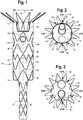
FIG. 1 shows a front view of a bifurcated prosthesis with an internal limb; -
FIG. 2 shows a top view of the bifurcated prosthesis ofFIG. 1 ; -
FIG. 3 shows a bottom view of the bifurcated prosthesis ofFIG. 1 ; -
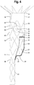
FIG. 4 shows a side view of the bifurcated prosthesis ofFIG. 1 ; -
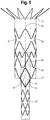
FIG. 5 shows a rear view of the bifurcated prosthesis ofFIG. 1 ; -
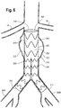
FIG. 6 shows a perspective view of an existing prosthesis inside a patient's body that needs repair; -
FIG. 7 shows a perspective view of the bifurcated prosthesis ofFIG. 1 inserted within the existing prosthesis ofFIG. 6 inside the patient's body; and -
FIG. 8 shows a perspective view of an iliac limb extension inserted into the bifurcated prosthesis ofFIG. 1 and the existing prosthesis ofFIG. 6 inside the patient's body. - In the present disclosure, the term "proximal" refers to a direction that is generally closest to the heart during a medical procedure, while the term "distal" refers to a direction that is farthest from the heart during a medical procedure.
- The term "fenestration" refers to an opening provided through a surface of a prosthesis from the interior of the prosthesis to the exterior of the prosthesis. A fenestration may have any one of a variety of geometries including circular, semi-circular, oval, oblong, diamond, or other geometries.
- The term "prosthesis" refers to any device for insertion or implantation into or replacement for a body part or a function of that body part. The term also may refer to a device that enhances or adds functionality to a physiological system. The term prosthesis may include, for example and without limitation, a stent, stent-graft, filter, valve, balloon, embolization coil, and the like.
-
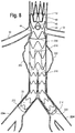
FIG. 1 shows a front view of aprosthesis 10. Theprosthesis 10 may include a bifurcated stent graft including aproximal end 12, adistal end 14, adiameter 16, a tubularmain body 18 that extends from theproximal end 12 to thedistal end 14, and aninternal lumen 20. Theprosthesis 10 also includes one externaldistal leg 22 or a first limb that extends distally from thedistal end 14 of theprosthesis 10. Theprosthesis 10 also includes afrustoconical midsection 21 adjacent to and on a side opposite to the externaldistal leg 22 and afenestration 24 that is located in thefrustoconical midsection 21, as shown inFIGS. 4-5 . Some bifurcated stent grafts may include two external distal legs; however, the bifurcated stent graft in the present disclosure includes one externaldistal leg 22 and thefenestration 24. The externaldistal leg 22 can be sized and dimensioned for insertion into an iliac artery or existing stent graft limb / leg / body. - The
fenestration 24 includes a diamond shaped fenestration, as shown inFIG. 5 . In other examples, thefenestration 24 of theprosthesis 10 may include circular, semi-circular, oval, oblong, or other geometries, and the diamond shape may include a geometry of a diamond, rhombus or parallelogram shape with oblique angles or non-oblique angles, sides with equal or varying lengths, or approximate geometries or the same, e.g. a diamond shape with rounded corners or a diamond shape that may include minor sides in addition to the four main sides, and such examples are within the scope of this disclosure. - The
internal limb 26 extends from thefenestration 24 and into theinternal lumen 20 of the tubularmain body 18 toward theproximal end 12 of theprosthesis 10. Theinternal limb 26 comprises aproximal end 28, adistal end 30, atubular body 32 that extends from theproximal end 28 to thedistal end 30, and aninternal lumen 34. The internal limb is made of a graft material that may include a flexible material, such as polytetrafluoroethylene (PTFE) or expanded PTFE (ePTFE), a polyester material, or other materials that allow for a seal with theprosthesis 10. The material allows aninternal limb 26 to be easily expanded and collapsed. - The
internal limb 26 may also include aring 36 positioned at theproximal end 28 of theinternal limb 26. Thering 36 maintains the patency of theinternal lumen 34 of theinternal limb 26 and provides structure to theinternal limb 26. Thering 36 also allows for something to seal against, while also minimizing packing density because it will collapse during loading of theinternal limb 26. The material of thering 36 may include nitinol or other shape memory or elastic metal. As shown inFIG. 2 , thering 36 may be sewn or stitched to theproximal end 28 of theinternal limb 26. Thering 36 may have a pure circular or other shape, which may aid in support, packing, and/or collapse. - The
prosthesis 10 and theinternal limb 26 may include a plurality ofstents 38, such as the Z-stent or Gianturco stent design, or be free of stents. As shown inFIG. 1 , theprosthesis 10 includes the plurality ofstents 38 that are Z-stents. However, in other examples, theprosthesis 10 may be free of thestents 38. Also, as shown inFIG. 2 , theinternal limb 26 may be free ofstents 38. Although theinternal limb 26 is described as free of any stents, the disclosure is not so limited. In other examples, theinternal limb 26 may include a stent pattern such as the Z-stent or Gianturco stent design, and such examples are within the scope of this disclosure. Each Z-stent may include a series of substantially straight segments or struts interconnected by a series of bent segments or bends. The bent segments may include acute bends or apices. The Z-stents are arranged in a ZigZag configuration in which the straight segments are set at angles relative to one another and are connected by the bent segments. This design provides both significant radial force as well as longitudinal support. In tortuous anatomy, branches, or fenestrations, it may be preferable to use alternative stents or modifications to the Z-stent design to avoid stent-to-stent contact. Alternative stents may include, for example, annular or helical stents. Furthermore, in complex anatomical situations, external stents may have the potential to become intertwined with the wires or other devices utilized to ensure branch vessel access, sealing, and fixation. Thus, in some instances, it may be desirable to affix some of thestents 38 to the external and/or internal surfaces of theinternal limb 26. - The tubular
main body 18 of theprosthesis 10 includes ananterior side 40 and aposterior side 42. The anterior andposterior sides internal lumen 20. Theanterior side 40 may extend circumferentially around approximately half of the circumference of the tubularmain body 18. Theposterior side 42 may extend circumferentially around approximately the other half of the circumference of the tubularmain body 18. Theposterior side 42 of the tubularmain body 18 may be positioned opposite theanterior side 40 with respect to the circumference of the tubularmain body 18. In other words, a plane may be defined to include the longitudinal axis of the tubularmain body 18. Theanterior side 40 may be positioned on one side of the plane, and theposterior side 42 may be positioned on the opposite side of the plan from theanterior side 40. Theanterior side 40 and theposterior side 42 may cooperatively form the tubularmain body 18. - The tubular
main body 18 may include a plurality of fenestrations in addition tofenestration 24. The plurality of fenestrations may be pivotable or non-pivotable. The tubularmain body 18 may include twopivotable fenestrations 44, anon-pivotable fenestration 46, and ascallop 48 as shown inFIGS. 1-2 ,4-5 , and7-8 . Although the tubularmain body 18 is described as including two pivotable fenestrations 33 and anon-pivotable fenestration 46, the disclosure is not so limited. In other examples, any of the fenestrations may be pivotable or non-pivotable, and such examples are within the scope of this disclosure. The pivotable fenestrations 445 may be positioned on the tubularmain body 18 to radially align with, for example, therenal arteries 50, as shown inFIGS. 7-8 . Thenon-pivotable fenestration 46 may be positioned on the tubularmain body 18 to radially align with, for example, the superior mesenteric artery (SMA). Thescallop 48 may be configured to align with the celiac artery. It will be recognized by one of ordinary skill in the art that theprosthesis 10 may include any number of openings or fenestrations of any type. Also, the fenestrations may be arranged on theprosthesis 10 in any manner. Preferably, the fenestrations may be arranged to correspond to a particular position within the anatomy into which theprosthesis 10 is intended to be placed. - The pivotable fenestrations 44 may include an
inner perimeter 52 surrounding thefenestration 44, aband 54 surrounding theinner perimeter 52, and anouter perimeter 56 surrounding theband 54, as shown inFIG. 4 . Theouter perimeter 56 may have a diameter that is greater than a diameter of theinner perimeter 52. Theinner perimeter 52, theband 54, and theouter perimeter 56 may be substantially concentric with one another if brought into the same plane, for example, the surface plane of the graft. Theinner perimeter 52, theband 54, and theouter perimeter 56 may form an extension having a hemispherical shape, resembling a dome, or a frustoconical cone extending from the surface of the tubularmain body 18. Thepivotable fenestration 44 may be positioned at the peak or top of the extension. Thepivotable fenestration 44 may be placed in a concave orientation or a convex orientation. In the concave orientation, the extension may extend into theinternal lumen 20 of the tubularmain body 18, as shown inFIG. 2 . In the convex orientation, the extension may extend away from theinternal lumen 20. Thepivotable fenestration 44 may be movable between the concave orientation and the convex orientation. Thepivotable fenestration 44 also may be placed in any position between the concave orientation and the convex orientation. For example, theband 54 may be folded, bent, gathered, pleated, or otherwise manipulated such that thefenestration 44 is generally aligned with the surface plane of the tubularmain body 18. - The
outer perimeter 56 of thepivotable fenestration 44 may be affixed to the tubularmain body 18 by any attachment method including suturing circumferentially about an aperture disposed through the tubularmain body 18. Theband 54 may be sufficiently flexible to permit thefenestration 44 to move such that a branch prosthesis disposed in thefenestration 44 may be oriented upwardly, downwardly, laterally, diagonally, and the like relative to the surface of the tubularmain body 18. In some examples, theband 54 may permit thefenestration 44 to move up to about 180 degrees relative to the surface plane of the tubularmain body 18. Accordingly, thepivotable fenestration 44 may allow theprosthesis 10 to be used in a variety of patients due to its ability to adapt to the variance in the positioning of the diseased branch vessels. For example, if a branch vessel is or becomes offset longitudinally or axially from apivotable fenestration 44, thepivotable fenestration 44 may pivot theprosthesis 10 in the necessary direction and to the necessary degree to maintain theprosthesis 10 in place in the branch vessel. - An advantageous characteristic of the
fenestrations scallop 48 on theprosthesis 10 is to maintain blood flow to the visceral vessels, including therenal arteries 50, the superior mesenteric artery, and the celiac artery, after implantation of theprosthesis 10 within the abdominal aorta. In some instances, thefenestrations internal limb 26 is inserted through thefenestration 24 and into theinternal lumen 20 of the tubularmain body 18, theinternal limb 26 occupies a portion of theinternal lumen 20. Therefore, positioning theinternal limb 26 within theinternal lumen 20 to avoid thefenestrations internal lumen 20 of the tubularmain body 18. - For example, the
prosthesis 10 may be configured to extend between a point proximal to therenal arteries 50 and a point distal to therenal arteries 50. Thus, thescallop 48 may be configured to align with the celiac artery, the pivotable fenestrations 44 may be configured to align with therenal arteries 50, and thenon-pivotable fenestration 46 may be configured to align with the superior mesenteric artery. As previously described, although the tubularmain body 18 is described as including twopivotable fenestrations 44 and anon-pivotable fenestration 46, the disclosure is not so limited. In other examples, any of the fenestrations may be pivotable or non-pivotable, and such examples are within the scope of this disclosure. Thescallop 48 may be positioned circumferentially on ananterior point 58 of the tubularmain body 18 and longitudinally at theproximal end 12 of the tubularmain body 18. Theanterior point 58 may extend generally longitudinally along the tubularmain body 18 and may be substantially circumferentially centered on theanterior side 40 of the tubularmain body 18, as shown inFIG. 1 . The tubularmain body 18 also includes aposterior point 60 that is substantially circumferentially centered on theposterior side 42 of the tubularmain body 18, as shown inFIG. 5 . - The
non-pivotable fenestration 46 may be positioned circumferentially on theanterior point 58 of the tubularmain body 18 and longitudinally distal to thescallop 48. The pivotable fenestrations 44 may be spaced from one another by a predetermined distance around the circumference of the tubular main body 19. For example, the firstpivotable fenestration 44a may be configured to align with the rightrenal artery 50 and may be spaced a first circumferential distance from theanterior point 58 of the tubularmain body 18. The secondpivotable fenestration 44b may be configured to align with the leftrenal artery 50 and may be spaced a second circumferential distance from theanterior point 58 of the tubularmain body 18. The first and second circumferential distances may be of substantially equal lengths in opposite directions relative to theanterior point 58 of the tubularmain body 18. Alternatively, the first and second circumferential distances may be different from one another, for example, to correspond to the anatomy of a particular patient or patients. The first and second pivotable fenestrations 44a, 44b may be positioned at substantially the same longitudinal position along the tubular main body 76. Alternatively, the first and second pivotable fenestrations 85a, 85b may be offset longitudinally with respect to one another, for example, to correspond to the anatomy of a particular patient or patients. The first and second pivotable fenestrations 44a, 44b may be positioned longitudinally distal to thenon-pivotable fenestration 46 and thescallop 48, as shown inFIG. 4 . As shown inFIGS. 1-2 , the pivotable fenestrations 44 may be positioned circumferentially centered between the anterior andposterior sides anterior side 40 or theposterior side 42. - The external
distal leg 22 and thefenestration 24 are spaced apart from one another by a predetermined distance around the circumference of theprosthesis 10. Specifically, thedistal leg 22 is positioned longitudinally distal to thenon-pivotal fenestration 46 and spaced a circumferential distance from theanterior point 58 of the tubularmain body 18. Thefenestration 24 is also positioned longitudinally distal to thenon-pivotal fenestration 46 and spaced a circumferential distance from theanterior point 58 of the tubularmain body 18. The circumferential distance of thedistal leg 22 and thefenestration 24 from theanterior point 58 is approximately equal. Thus, thedistal leg 22 and thefenestration 24 may be positioned on theprosthesis 10 approximately 90 degrees from theanterior point 58 of the tubularmain body 18 with respect to the circumference of theprosthesis 10 in opposite directions, or in other words, thedistal leg 22 and thefenestration 24 may be positioned on opposite sides of theprosthesis 10 relative to theanterior point 58. For example, thedistal leg 22 and thefenestration 24 may be circumferentially centered between the anterior andposterior sides main body 18 and 180 degrees from one another with respect to the circumference of the tubularmain body 18 as shown inFIGS. 1-3 . - As shown in
FIGS. 2-4 , when theinternal limb 26 extends from thefenestration 24 into theinternal lumen 20 toward theproximal end 12 of theprosthesis 10 and along theposterior side 42 of the tubularmain body 18. In other words, theinternal limb 26 extends vertically through theinternal limb 26 and along theposterior side 42 of the tubularmain body 18 such that theinternal limb 26 is positioned in theinternal lumen 20 along theposterior point 60 to avoid the pivotable fenestrations 44 andnon-pivotable fenestration 46. - The
internal limb 26 may be sewn, sutured or stitched 62 to the stent graft body of the tubularmain body 18 to maintain the positioning of theinternal limb 26 within theprosthesis 10, as shown inFIG. 5 . Theinternal limb 26 is only sewn, sutured, or stitched 62 along the side of its tubular wall that is in contact with the tubularmain body 18 to ensure theinternal limb 26 maintains its position and (if desired) patency within theinternal lumen 20. For example, as shown inFIG. 5 , theinternal limb 26 may be sewn, sutured, or stitched 62 along theposterior side 42 andposterior point 60 of theprosthesis 10. - The
fenestration 24 with theinternal limb 26 connected to thefenestration 24 may not take its shape naturally. Thus, theinternal limb 26 creates a shelf-like configuration when attached to thefenestration 24 and opens thefenestration 24. For example, as shown inFIG. 4 , the proximal half of thefenestration 24 may collapse distally and lies at an angle, such as 90 degrees or greater, to the distal half of thefenestration 24. This orientation or shelf-like configuration of thefenestration 24 creates an effectively larger target for an approaching wire, catheter, dilator or other device to be easily inserted through thefenestration 24 and facilitates cannulation. - As shown in
FIG. 5 , theinternal limb 26 also creates a smooth seamless slope orpath 64 for an approaching wire, catheter, dilator or other device to be inserted through thefenestration 24 and slide unimpeded through theinternal limb 26. As described previously, the smooth seamless slope 100 allows for ease of cannulation and minimizes the areas where an approaching wire, catheter, dilator or other device may catch or snag when moving through theinternal limb 26. - The circumferential positions of the various components or features of the
prosthesis 10 may be described with reference to a clock face as shown inFIGS. 2-3 . For example, the clock face may be positioned such that 12 o'clock corresponds to theanterior point 58 of theprosthesis 10 and 6 o'clock corresponds to theposterior point 60 of theprosthesis 10, such as looking up from a patient's distal aorta. Thus, thenon-pivotable fenestration 46 and/or thescallop 48 may be positioned circumferentially at approximately 12 o'clock, i.e., along theanterior point 58 of theprosthesis 10. The pivotable fenestrations 44 may be positioned circumferentially on theprosthesis 10 at 3 o'clock and 9 o'clock. In other examples, the pivotable fenestrations 44 may be positioned circumferentially between approximately 1:30 to 3:00 o'clock and between approximately 9:00 to 10:30 o'clock, respectively. Such positioning may vary to enable the pivotable fenestrations 44 to generally align with therenal arteries 50 as previously described. The externaldistal leg 22 may be positioned circumferentially at 12 o'clock and thefenestration 24 may be positioned circumferentially at 6 o'clock. Theinternal limb 26 may be positioned circumferentially at 6 o'clock such that theproximal end 28 ofinternal limb 26 is positioned circumferentially at 6 o'clock as shown inFIGS. 2-3 . Thus, the orientation of theinternal limb 26 to the clock position of 6 o'clock positions theinternal limb 26 away from thefenestrations scallop 48 to minimize interference within theprosthesis 10. - The
prosthesis 10 with theinternal limb 26 may be inserted into an original or existingprosthesis 200 that needs repair. Theinternal limb 26 allows a wire, catheter, dilator or other device, such as an iliac limb extension, to be inserted through the original or existing stent graft leg or limb and theinternal limb 26 and for cannulation of the contralateral gate of theprosthesis 10, or the side of theprosthesis 10 opposite the externaldistal leg 22 of theprosthesis 10, through the existing stent graft leg or limb. -
FIGS. 6-8 show an example of an existingprosthesis 200 that is a bifurcated prosthesis inside a patient's body over ananeurysm 202. The existingprosthesis 200 includes astent graft body 204 that includes a maintubular body 206 having aproximal end 208 and adistal end 210, afirst limb 212 extending from thedistal end 210 of the maintubular body 206, and asecond limb 214 also extending from thedistal end 210 of the maintubular body 206. Thefirst limb 212 and thesecond limb 214 extend through the patient'siliac arteries 224. AlthoughFIGS. 6-8 show theproximal end 208 of the maintubular body 206 of the existingprosthesis 200 positioned below therenal arteries 50, the existingprosthesis 200 may be positioned above or next to therenal arteries 50. In such an example, the existingprosthesis 200 may also include fenestrations within thestent graft body 204 to allow blood flow from therenal arteries 50. Similar to theprosthesis 10, the existingprosthesis 200 may include a plurality of stents, as described previously above, or be free of stents. InFIGS. 6-8 , the existingprosthesis 200 includes a plurality of stents 222. - The main
tubular body 206 of the existingprosthesis 200 includes ananterior side 216 and aposterior side 218. The anterior andposterior sides tubular body 206. Theanterior side 216 may extend circumferentially around approximately half of the circumference of the maintubular body 206. Theposterior side 218 may extend circumferentially around approximately the other half of the circumference of the maintubular body 206. Theposterior side 218 of the maintubular body 206 may be positioned opposite theanterior side 216 with respect to the circumference of the maintubular body 206. In other words, a plane may be defined to include the longitudinal axis of the maintubular body 206. Theanterior side 216 may be positioned on one side of the plane, and theposterior side 218 may be positioned on the opposite side of the plan from theanterior side 216. Theanterior side 216 and theposterior side 218 may cooperatively form the maintubular body 206. The first andsecond limbs posterior sides -
FIG. 7 shows theprosthesis 10 inserted into the existingprosthesis 200. The pivotable fenestrations 44 of theprosthesis 10 are positioned to align with therenal arteries 50 and therefore theproximal end 12 of the tubularmain body 18 of theprosthesis 10 extends beyond theproximal end 208 of the maintubular body 206 of the existingprosthesis 200. The externaldistal leg 22 and thefenestration 24 of theprosthesis 10 are offset from the first andsecond limbs prosthesis 200. Specifically, since the externaldistal leg 22 of theprosthesis 10 is positioned along theanterior point 58 of theprosthesis 10, and thefirst limb 212 is positioned circumferentially centered between the anterior andposterior sides prosthesis 200, the externaldistal leg 22 of theprosthesis 10 must be shifted to be inserted into thefirst limb 212. Thus, to insert the externaldistal leg 22 into thefirst limb 212 of the existingprosthesis 200, the externaldistal leg 22 is moved to be positioned at an angle from theanterior point 58 of theprosthesis 10, as shown inFIG. 7 . -
FIG. 8 shows aniliac limb extension 220 that is inserted into thesecond limb 214 of the existingprosthesis 200 and then through thefenestration 24 and theinternal limb 26 of theprosthesis 10. Theiliac limb extension 220 includes a tubular stent graft body. Thefenestration 24 and theinternal limb 26 of theprosthesis 10 are offset from thesecond limb 214 of the existingprosthesis 200. Specifically, since thefenestration 24 and theinternal limb 26 of theprosthesis 10 are circumferentially centered on theposterior side 60 of theprosthesis 10, and thesecond limb 214 is positioned circumferentially centered between the anterior andposterior sides prosthesis 200, theiliac limb extension 220 is rotated to be inserted into thefenestration 24 and theinternal limb 26. In other words, theiliac limb extension 220 extends through thesecond limb 214 and is rotated toward theposterior side 60 of theprosthesis 10 to extend through thefenestration 24 and theinternal limb 26 of theprosthesis 10. Theprosthesis 10 and theiliac limb extension 220 repair the existingprosthesis 200. - It will be appreciated by those skilled in the art that changes could be made to the embodiments described above without departing from the broad inventive concept therefore. It is understood, therefore, that this invention is not limited to the particular embodiments disclosed, but it is intended to cover modifications within the spirit and scope of the present invention as defined by the claims.
- The disclosures in
US provisional patent application serial no. 62/458,778
Claims (16)
- A bifurcated endovascular prosthesis including:a tubular main body having a diameter, a proximal end, a distal end, an internal lumen extending from the proximal end to the distal end, an anterior side, and a posterior side, the anterior and posterior sides being opposite each other circumferentially around the internal lumen;a first limb extending from the distal end of the tubular main body along the anterior side of the main body, the first limb having a diameter less than the diameter of the tubular main body, the first limb having a proximal end and a distal end;a fenestration adjacent to the proximal end of the first limb, the fenestration extending from the proximal end of the first limb to the posterior side of the tubular main body;a second limb extending within the internal lumen from the fenestration toward the proximal end of the tubular main body;wherein the fenestration has a substantially diamond shape and a nonlinear profile; andwherein the second limb extends into the lumen along the posterior side of the tubular main body.
- A prosthesis according to claim 1, wherein the prosthesis includes a pivotable fenestration positioned between the anterior and posterior sides of the tubular main body.
- A prosthesis according to claim 1 or 2, wherein the prosthesis includes a second pivotable fenestration positioned between the anterior and poster sides of the tubular main body and circumferentially opposite to the first pivotable fenestration.
- A prosthesis according to claim 1, 2 or 3, wherein the prosthesis includes a pivotable or non-pivotable fenestration positioned on the anterior side of the tubular main body.
- A prosthesis according to any preceding claim, wherein the prosthesis includes a scallop positioned on the anterior side of the tubular main body and adjacent to the proximal end of the tubular main body.
- A prosthesis according to any preceding claim, wherein:the first limb is circumferentially centered on the anterior side of the tubular main body, and/orthe fenestration is circumferentially centered on the posterior side of the tubular main body.
- A prosthesis according to any preceding claim, wherein the tubular main body and the first limb comprise a plurality of stents.
- A bifurcated endovascular prosthesis comprising:a tubular main body having a diameter, a proximal end, a distal end, an internal lumen extending from the proximal end to the distal end, an anterior side, and a posterior side, the anterior and posterior sides being opposite each other circumferentially around the internal lumen;a first limb extending from the distal end of the tubular main body along the anterior side of the main body and circumferentially centered on the anterior side of the main body, the first limb having a tubular body, a proximal end and a distal end;a fenestration adjacent to the proximal end of the first limb, the fenestration extending from the proximal end of the first limb to the posterior side of the tubular main body;a second limb extending within the internal lumen from the fenestration toward the proximal end of the tubular main body;wherein the fenestration has a substantially diamond shape and a nonlinear profile; andwherein the second limb extends into the lumen along the posterior side of the tubular main body and is circumferentially centered on the posterior side of the tubular main body.
- A prosthesis according to claim 8, wherein the prosthesis includes a pivotable fenestration positioned between the anterior and posterior sides of the tubular main body.
- A prosthesis according to claim 8 or 9, wherein the prosthesis includes a second pivotable fenestration positioned between the anterior and poster sides of the tubular main body and circumferentially opposite to the first pivotable fenestration.
- A prosthesis according to claim 8, 9 or 10, wherein the prosthesis includes a pivotable or non-pivotable fenestration positioned on the anterior side of the tubular main body.
- A prosthesis according to any one of claims 8 to 11, wherein the prosthesis includes a scallop positioned on the anterior side of the tubular main body and adjacent to the proximal end of the tubular main body.
- A prosthesis according to any one of claims 8 to 12, wherein a diameter of the first limb is smaller than the diameter of the tubular main body of the prosthesis.
- A prosthesis according to any one of claims 8 to 13, wherein the tubular main body and the first limb comprise a plurality of stents.
- A method of cannulating a contralateral gate of a bifurcated prosthesis, the method comprising:inserting the bifurcated prosthesis into an existing bifurcated prosthesis;wherein the existing bifurcated prosthesis comprises:a tubular main body having a diameter, a proximal end, a distal end, an internal lumen extending from the proximal end to the distal end, an anterior side, and a posterior side, the anterior and posterior sides being opposite each other circumferentially around the internal lumen;a first limb extending from the distal end of the tubular main body and circumferentially centered between the anterior and posterior sides;a second limb extending from the distal end of the tubular main body and circumferentially centered between the anterior and posterior sides;wherein the first and second limbs are positioned opposite to each other circumferentially around the internal lumen of the existing bifurcated prosthesis;wherein the bifurcated prosthesis comprises:a tubular main body having a diameter, a proximal end, a distal end, an internal lumen extending from the proximal end to the distal end, an anterior side, and a posterior side, the anterior and posterior sides being opposite each other circumferentially around the internal lumen;a first limb extending from the distal end of the tubular main body along the anterior side of the main body and circumferentially centered on the anterior side of the main body, the first limb having a tubular body, a proximal end and a distal end;a fenestration adjacent to the proximal end of the first limb, the fenestration extending from the proximal end of the first limb to the posterior side of the tubular main body;a second limb extending within the internal lumen from the fenestration toward the proximal end of the tubular main body;
wherein the fenestration has a substantially diamond shape and a nonlinear profile; andwherein the second limb extends into the lumen along the posterior side of the tubular main body and is circumferentially centered on the posterior side of the tubular main body;wherein inserting the bifurcated prosthesis into the existing bifurcated prosthesis comprises inserting the tubular main body of the bifurcated prosthesis into the tubular main body of the existing bifurcated prosthesis, inserting the first limb of the bifurcated prosthesis into the first limb of the existing bifurcated prosthesis, and positioning the fenestration of the bifurcated prosthesis over the second limb of the existing bifurcated prosthesis; andinserting a limb extension having a tubular body, a proximal end, and a distal end, into the second limb of the existing bifurcated prosthesis through the fenestration of the bifurcated prosthesis and through the second limb of the bifurcated prosthesis. - A method according to claim 15, wherein:inserting the first limb of the bifurcated prosthesis into the first limb of the existing bifurcated prosthesis comprises shifting the distal end of the first limb of the bifurcated prosthesis into the first limb of the existing bifurcated prosthesis such that the first limb of the bifurcated prosthesis extends at an angle from the distal end of the tubular main body of the bifurcated prosthesis; and/orinserting the limb extension into the second limb of the existing bifurcated prosthesis through the fenestration of the bifurcated prosthesis and through the second limb of the bifurcated prosthesis comprises the limb extension extending through the second limb of the existing bifurcated prosthesis and then extending an angle from the second limb of the existing bifurcated prosthesis through the fenestration and the second limb of the bifurcated prosthesis.
Applications Claiming Priority (1)
| Application Number | Priority Date | Filing Date | Title |
|---|---|---|---|
| US201762458778P | 2017-02-14 | 2017-02-14 |
Publications (2)
| Publication Number | Publication Date |
|---|---|
| EP3360510A1 true EP3360510A1 (en) | 2018-08-15 |
| EP3360510B1 EP3360510B1 (en) | 2020-09-09 |
Family
ID=61192830
Family Applications (1)
| Application Number | Title | Priority Date | Filing Date |
|---|---|---|---|
| EP18275017.4A Active EP3360510B1 (en) | 2017-02-14 | 2018-02-09 | A bifurcated prosthesis with an internal limb |
Country Status (2)
| Country | Link |
|---|---|
| US (1) | US10729532B2 (en) |
| EP (1) | EP3360510B1 (en) |
Families Citing this family (13)
| Publication number | Priority date | Publication date | Assignee | Title |
|---|---|---|---|---|
| CN109803607B (en) | 2016-06-13 | 2021-07-20 | 主动脉公司 | Systems, devices and methods for marking and/or reinforcing fenestrations in prosthetic implants |
| JP7181856B2 (en) * | 2016-08-02 | 2022-12-01 | ボルトン メディカル インコーポレイテッド | Systems, instruments, and methods for bonding prosthetic implants to fenestrated bodies |
| GB201615219D0 (en) | 2016-09-07 | 2016-10-19 | Vascutek Ltd And Univ Medical Center Hamburg-Eppendorf (Uke) | Hybrid prosthesis and delivery system |
| US11446168B2 (en) | 2017-04-25 | 2022-09-20 | Cook Medical Technologies Llc | Prosthesis with side branch and method of making the same |
| GB2562065A (en) * | 2017-05-02 | 2018-11-07 | Vascutek Ltd | Endoprosthesis |
| GB201707929D0 (en) | 2017-05-17 | 2017-06-28 | Vascutek Ltd | Tubular medical device |
| CN115813605A (en) | 2017-09-25 | 2023-03-21 | 波尔顿医疗公司 | Systems, devices and methods for coupling prosthetic implants to fenestrations |
| GB201820899D0 (en) | 2018-12-20 | 2019-02-06 | Vascutek Ltd | Stent device delivery tool and associated method of use |
| GB201820898D0 (en) | 2018-12-20 | 2019-02-06 | Vascutek Ltd | Stent device |
| GB201909789D0 (en) | 2019-07-08 | 2019-08-21 | Vascutek Ltd | Stent graft |
| US12697203B2 (en) | 2022-10-17 | 2026-08-04 | Cook Medical Technologies Llc | Stent graft assembly |
| GB2623515B (en) * | 2022-10-17 | 2025-04-02 | Cook Medical Technologies Llc | Stent graft assembly |
| GB2625479B (en) * | 2022-10-17 | 2025-08-13 | Cook Medical Technologies Llc | Stent graft assembly |
Citations (4)
| Publication number | Priority date | Publication date | Assignee | Title |
|---|---|---|---|---|
| WO2006034276A1 (en) * | 2004-09-21 | 2006-03-30 | William A. Cook Austrialia Pty. Ltd. | Side branch stent graft |
| WO2011100290A1 (en) * | 2010-02-09 | 2011-08-18 | Cook Medical Technologies Llc | Thoracic aorta stent graft |
| US20150057737A1 (en) * | 2013-08-23 | 2015-02-26 | Cook Medical Technologies Llc | Stent Graft Assembly for Treating Branched Vessels |
| WO2015061669A1 (en) * | 2013-10-24 | 2015-04-30 | The Cleveland Clinic Foundation | Branched vessel prosthesis for repair of a failed stent graft |
Family Cites Families (23)
| Publication number | Priority date | Publication date | Assignee | Title |
|---|---|---|---|---|
| US6325826B1 (en) | 1998-01-14 | 2001-12-04 | Advanced Stent Technologies, Inc. | Extendible stent apparatus |
| AUPP083597A0 (en) | 1997-12-10 | 1998-01-08 | William A Cook Australia Pty Ltd | Endoluminal aortic stents |
| US6395018B1 (en) | 1998-02-09 | 2002-05-28 | Wilfrido R. Castaneda | Endovascular graft and process for bridging a defect in a main vessel near one of more branch vessels |
| US7014653B2 (en) | 2001-12-20 | 2006-03-21 | Cleveland Clinic Foundation | Furcated endovascular prosthesis |
| US6949121B1 (en) | 2002-02-07 | 2005-09-27 | Sentient Engineering & Technology, Llc | Apparatus and methods for conduits and materials |
| US9125733B2 (en) | 2003-01-14 | 2015-09-08 | The Cleveland Clinic Foundation | Branched vessel endoluminal device |
| WO2006113501A1 (en) | 2005-04-13 | 2006-10-26 | The Cleveland Clinic Foundation | Endoluminal prosthesis |
| US7955374B2 (en) | 2005-09-02 | 2011-06-07 | Medtronic Vascular, Inc. | Modular branch vessel stent-graft assembly |
| US8623005B2 (en) | 2007-10-01 | 2014-01-07 | Baylis Medical Company Inc. | Stent graft fenestration |
| US7963960B2 (en) | 2006-11-07 | 2011-06-21 | Medtronic Vascular, Inc. | Cutting radio frequency catheter for creating fenestrations in graft cloth |
| US20090125097A1 (en) | 2007-11-13 | 2009-05-14 | Medtronic Vascular, Inc. | Device and Method for Stent Graft Fenestration in Situ |
| US20090228020A1 (en) | 2008-03-06 | 2009-09-10 | Hansen Medical, Inc. | In-situ graft fenestration |
| US8100960B2 (en) | 2008-03-20 | 2012-01-24 | Medtronic Vascular, Inc. | Bloused stent-graft and fenestration method |
| US20090259290A1 (en) | 2008-04-14 | 2009-10-15 | Medtronic Vascular, Inc. | Fenestration Segment Stent-Graft and Fenestration Method |
| US20090264988A1 (en) | 2008-04-18 | 2009-10-22 | Medtronic Vascular, Inc. | Stent Graft Delivery System Including Support for Fenestration in Situ and a Mechanism for Modeling |
| WO2010024849A1 (en) | 2008-08-29 | 2010-03-04 | Cook Incorporated | Prosthesis with moveable fenestration |
| EP2416734A1 (en) | 2009-04-02 | 2012-02-15 | The Medical Research, Infrastructure, And Health Services Fund Of The Tel Aviv Medical Center | Stent graft fenestration |
| US9358099B2 (en) | 2009-11-30 | 2016-06-07 | Biflow Medical Ltd. | Method of implanting a stent graft and creating a fenestration therein |
| US9737394B2 (en) | 2012-04-27 | 2017-08-22 | Medtronic Vascular, Inc. | Stent-graft prosthesis for placement in the abdominal aorta |
| US9811613B2 (en) | 2012-05-01 | 2017-11-07 | University Of Washington Through Its Center For Commercialization | Fenestration template for endovascular repair of aortic aneurysms |
| GB201316738D0 (en) | 2013-09-20 | 2013-11-06 | Rainbow Medical Engineering Ltd | Implantable Medical Devices |
| WO2015063780A2 (en) | 2013-11-04 | 2015-05-07 | Biflow Medical Ltd. | A device and method of implanting a stent graft and forming a fenestration therein |
| US10758387B2 (en) | 2014-10-16 | 2020-09-01 | Cook Medical Technologies Llc | Endovascular stent graft assembly and delivery device |
-
2018
- 2018-02-01 US US15/886,061 patent/US10729532B2/en active Active
- 2018-02-09 EP EP18275017.4A patent/EP3360510B1/en active Active
Patent Citations (4)
| Publication number | Priority date | Publication date | Assignee | Title |
|---|---|---|---|---|
| WO2006034276A1 (en) * | 2004-09-21 | 2006-03-30 | William A. Cook Austrialia Pty. Ltd. | Side branch stent graft |
| WO2011100290A1 (en) * | 2010-02-09 | 2011-08-18 | Cook Medical Technologies Llc | Thoracic aorta stent graft |
| US20150057737A1 (en) * | 2013-08-23 | 2015-02-26 | Cook Medical Technologies Llc | Stent Graft Assembly for Treating Branched Vessels |
| WO2015061669A1 (en) * | 2013-10-24 | 2015-04-30 | The Cleveland Clinic Foundation | Branched vessel prosthesis for repair of a failed stent graft |
Also Published As
| Publication number | Publication date |
|---|---|
| US10729532B2 (en) | 2020-08-04 |
| EP3360510B1 (en) | 2020-09-09 |
| US20180228593A1 (en) | 2018-08-16 |
Similar Documents
| Publication | Publication Date | Title |
|---|---|---|
| EP3360510B1 (en) | A bifurcated prosthesis with an internal limb | |
| EP3360511B1 (en) | Method of making a contoured internal limb for a prosthesis and prosthesis with a contoured internal limb | |
| US11801129B2 (en) | Vascular prosthesis with fenestration ring and methods of use | |
| JP4970944B2 (en) | Stent graft with opening | |
| AU2015268728B2 (en) | Endoluminal prosthesis with steerable branch | |
| US9095421B2 (en) | Multi-leaflet coupling for branch vessel connection | |
| AU2008323540B2 (en) | Hybrid intraluminal device | |
| US9855130B2 (en) | Preloaded wire for endoluminal device | |
| AU2013273638B9 (en) | Preloaded wire for endoluminal device | |
| JP6248308B2 (en) | Circumferentially constrained suture for stent graft | |
| EP3799832B1 (en) | Prosthesis with side branch | |
| EP2606851B1 (en) | Preloaded wire for endoluminal device | |
| CN109996514A (en) | Modularization arch of aorta prosthesis assembly and its application method | |
| EP2517673A2 (en) | Branch vessel prosthesis | |
| CN114423377A (en) | Aortic access trident modular stent assembly and method | |
| EP3135248A1 (en) | Endograft with one or more apertures | |
| EP4389069A1 (en) | Branchable stent graft | |
| AU2015261727B2 (en) | Preloaded wire for endoluminal device |
Legal Events
| Date | Code | Title | Description |
|---|---|---|---|
| PUAI | Public reference made under article 153(3) epc to a published international application that has entered the european phase |
Free format text: ORIGINAL CODE: 0009012 |
|
| STAA | Information on the status of an ep patent application or granted ep patent |
Free format text: STATUS: THE APPLICATION HAS BEEN PUBLISHED |
|
| AK | Designated contracting states |
Kind code of ref document: A1 Designated state(s): AL AT BE BG CH CY CZ DE DK EE ES FI FR GB GR HR HU IE IS IT LI LT LU LV MC MK MT NL NO PL PT RO RS SE SI SK SM TR |
|
| AX | Request for extension of the european patent |
Extension state: BA ME |
|
| STAA | Information on the status of an ep patent application or granted ep patent |
Free format text: STATUS: REQUEST FOR EXAMINATION WAS MADE |
|
| 17P | Request for examination filed |
Effective date: 20190215 |
|
| RBV | Designated contracting states (corrected) |
Designated state(s): AL AT BE BG CH CY CZ DE DK EE ES FI FR GB GR HR HU IE IS IT LI LT LU LV MC MK MT NL NO PL PT RO RS SE SI SK SM TR |
|
| GRAP | Despatch of communication of intention to grant a patent |
Free format text: ORIGINAL CODE: EPIDOSNIGR1 |
|
| STAA | Information on the status of an ep patent application or granted ep patent |
Free format text: STATUS: GRANT OF PATENT IS INTENDED |
|
| INTG | Intention to grant announced |
Effective date: 20200325 |
|
| GRAS | Grant fee paid |
Free format text: ORIGINAL CODE: EPIDOSNIGR3 |
|
| GRAA | (expected) grant |
Free format text: ORIGINAL CODE: 0009210 |
|
| STAA | Information on the status of an ep patent application or granted ep patent |
Free format text: STATUS: THE PATENT HAS BEEN GRANTED |
|
| AK | Designated contracting states |
Kind code of ref document: B1 Designated state(s): AL AT BE BG CH CY CZ DE DK EE ES FI FR GB GR HR HU IE IS IT LI LT LU LV MC MK MT NL NO PL PT RO RS SE SI SK SM TR |
|
| REG | Reference to a national code |
Ref country code: GB Ref legal event code: FG4D |
|
| REG | Reference to a national code |
Ref country code: AT Ref legal event code: REF Ref document number: 1310613 Country of ref document: AT Kind code of ref document: T Effective date: 20200915 Ref country code: CH Ref legal event code: EP |
|
| REG | Reference to a national code |
Ref country code: IE Ref legal event code: FG4D |
|
| REG | Reference to a national code |
Ref country code: DE Ref legal event code: R096 Ref document number: 602018007675 Country of ref document: DE |
|
| REG | Reference to a national code |
Ref country code: LT Ref legal event code: MG4D |
|
| PG25 | Lapsed in a contracting state [announced via postgrant information from national office to epo] |
Ref country code: LT Free format text: LAPSE BECAUSE OF FAILURE TO SUBMIT A TRANSLATION OF THE DESCRIPTION OR TO PAY THE FEE WITHIN THE PRESCRIBED TIME-LIMIT Effective date: 20200909 Ref country code: BG Free format text: LAPSE BECAUSE OF FAILURE TO SUBMIT A TRANSLATION OF THE DESCRIPTION OR TO PAY THE FEE WITHIN THE PRESCRIBED TIME-LIMIT Effective date: 20201209 Ref country code: NO Free format text: LAPSE BECAUSE OF FAILURE TO SUBMIT A TRANSLATION OF THE DESCRIPTION OR TO PAY THE FEE WITHIN THE PRESCRIBED TIME-LIMIT Effective date: 20201209 Ref country code: SE Free format text: LAPSE BECAUSE OF FAILURE TO SUBMIT A TRANSLATION OF THE DESCRIPTION OR TO PAY THE FEE WITHIN THE PRESCRIBED TIME-LIMIT Effective date: 20200909 Ref country code: HR Free format text: LAPSE BECAUSE OF FAILURE TO SUBMIT A TRANSLATION OF THE DESCRIPTION OR TO PAY THE FEE WITHIN THE PRESCRIBED TIME-LIMIT Effective date: 20200909 Ref country code: FI Free format text: LAPSE BECAUSE OF FAILURE TO SUBMIT A TRANSLATION OF THE DESCRIPTION OR TO PAY THE FEE WITHIN THE PRESCRIBED TIME-LIMIT Effective date: 20200909 Ref country code: GR Free format text: LAPSE BECAUSE OF FAILURE TO SUBMIT A TRANSLATION OF THE DESCRIPTION OR TO PAY THE FEE WITHIN THE PRESCRIBED TIME-LIMIT Effective date: 20201210 |
|
| REG | Reference to a national code |
Ref country code: AT Ref legal event code: MK05 Ref document number: 1310613 Country of ref document: AT Kind code of ref document: T Effective date: 20200909 |
|
| REG | Reference to a national code |
Ref country code: NL Ref legal event code: MP Effective date: 20200909 |
|
| PG25 | Lapsed in a contracting state [announced via postgrant information from national office to epo] |
Ref country code: LV Free format text: LAPSE BECAUSE OF FAILURE TO SUBMIT A TRANSLATION OF THE DESCRIPTION OR TO PAY THE FEE WITHIN THE PRESCRIBED TIME-LIMIT Effective date: 20200909 Ref country code: RS Free format text: LAPSE BECAUSE OF FAILURE TO SUBMIT A TRANSLATION OF THE DESCRIPTION OR TO PAY THE FEE WITHIN THE PRESCRIBED TIME-LIMIT Effective date: 20200909 Ref country code: PL Free format text: LAPSE BECAUSE OF FAILURE TO SUBMIT A TRANSLATION OF THE DESCRIPTION OR TO PAY THE FEE WITHIN THE PRESCRIBED TIME-LIMIT Effective date: 20200909 |
|
| PG25 | Lapsed in a contracting state [announced via postgrant information from national office to epo] |
Ref country code: RO Free format text: LAPSE BECAUSE OF FAILURE TO SUBMIT A TRANSLATION OF THE DESCRIPTION OR TO PAY THE FEE WITHIN THE PRESCRIBED TIME-LIMIT Effective date: 20200909 Ref country code: PT Free format text: LAPSE BECAUSE OF FAILURE TO SUBMIT A TRANSLATION OF THE DESCRIPTION OR TO PAY THE FEE WITHIN THE PRESCRIBED TIME-LIMIT Effective date: 20210111 Ref country code: CZ Free format text: LAPSE BECAUSE OF FAILURE TO SUBMIT A TRANSLATION OF THE DESCRIPTION OR TO PAY THE FEE WITHIN THE PRESCRIBED TIME-LIMIT Effective date: 20200909 Ref country code: EE Free format text: LAPSE BECAUSE OF FAILURE TO SUBMIT A TRANSLATION OF THE DESCRIPTION OR TO PAY THE FEE WITHIN THE PRESCRIBED TIME-LIMIT Effective date: 20200909 Ref country code: SM Free format text: LAPSE BECAUSE OF FAILURE TO SUBMIT A TRANSLATION OF THE DESCRIPTION OR TO PAY THE FEE WITHIN THE PRESCRIBED TIME-LIMIT Effective date: 20200909 |
|
| PG25 | Lapsed in a contracting state [announced via postgrant information from national office to epo] |
Ref country code: IS Free format text: LAPSE BECAUSE OF FAILURE TO SUBMIT A TRANSLATION OF THE DESCRIPTION OR TO PAY THE FEE WITHIN THE PRESCRIBED TIME-LIMIT Effective date: 20210109 Ref country code: ES Free format text: LAPSE BECAUSE OF FAILURE TO SUBMIT A TRANSLATION OF THE DESCRIPTION OR TO PAY THE FEE WITHIN THE PRESCRIBED TIME-LIMIT Effective date: 20200909 Ref country code: AT Free format text: LAPSE BECAUSE OF FAILURE TO SUBMIT A TRANSLATION OF THE DESCRIPTION OR TO PAY THE FEE WITHIN THE PRESCRIBED TIME-LIMIT Effective date: 20200909 Ref country code: AL Free format text: LAPSE BECAUSE OF FAILURE TO SUBMIT A TRANSLATION OF THE DESCRIPTION OR TO PAY THE FEE WITHIN THE PRESCRIBED TIME-LIMIT Effective date: 20200909 |
|
| REG | Reference to a national code |
Ref country code: DE Ref legal event code: R097 Ref document number: 602018007675 Country of ref document: DE |
|
| PG25 | Lapsed in a contracting state [announced via postgrant information from national office to epo] |
Ref country code: SK Free format text: LAPSE BECAUSE OF FAILURE TO SUBMIT A TRANSLATION OF THE DESCRIPTION OR TO PAY THE FEE WITHIN THE PRESCRIBED TIME-LIMIT Effective date: 20200909 |
|
| PLBE | No opposition filed within time limit |
Free format text: ORIGINAL CODE: 0009261 |
|
| STAA | Information on the status of an ep patent application or granted ep patent |
Free format text: STATUS: NO OPPOSITION FILED WITHIN TIME LIMIT |
|
| 26N | No opposition filed |
Effective date: 20210610 |
|
| PG25 | Lapsed in a contracting state [announced via postgrant information from national office to epo] |
Ref country code: DK Free format text: LAPSE BECAUSE OF FAILURE TO SUBMIT A TRANSLATION OF THE DESCRIPTION OR TO PAY THE FEE WITHIN THE PRESCRIBED TIME-LIMIT Effective date: 20200909 Ref country code: SI Free format text: LAPSE BECAUSE OF FAILURE TO SUBMIT A TRANSLATION OF THE DESCRIPTION OR TO PAY THE FEE WITHIN THE PRESCRIBED TIME-LIMIT Effective date: 20200909 |
|
| PG25 | Lapsed in a contracting state [announced via postgrant information from national office to epo] |
Ref country code: MC Free format text: LAPSE BECAUSE OF FAILURE TO SUBMIT A TRANSLATION OF THE DESCRIPTION OR TO PAY THE FEE WITHIN THE PRESCRIBED TIME-LIMIT Effective date: 20200909 |
|
| REG | Reference to a national code |
Ref country code: BE Ref legal event code: MM Effective date: 20210228 |
|
| PG25 | Lapsed in a contracting state [announced via postgrant information from national office to epo] |
Ref country code: CH Free format text: LAPSE BECAUSE OF NON-PAYMENT OF DUE FEES Effective date: 20210228 Ref country code: LI Free format text: LAPSE BECAUSE OF NON-PAYMENT OF DUE FEES Effective date: 20210228 Ref country code: IT Free format text: LAPSE BECAUSE OF FAILURE TO SUBMIT A TRANSLATION OF THE DESCRIPTION OR TO PAY THE FEE WITHIN THE PRESCRIBED TIME-LIMIT Effective date: 20200909 Ref country code: LU Free format text: LAPSE BECAUSE OF NON-PAYMENT OF DUE FEES Effective date: 20210209 |
|
| PG25 | Lapsed in a contracting state [announced via postgrant information from national office to epo] |
Ref country code: FR Free format text: LAPSE BECAUSE OF NON-PAYMENT OF DUE FEES Effective date: 20210228 |
|
| PG25 | Lapsed in a contracting state [announced via postgrant information from national office to epo] |
Ref country code: BE Free format text: LAPSE BECAUSE OF NON-PAYMENT OF DUE FEES Effective date: 20210228 |
|
| PG25 | Lapsed in a contracting state [announced via postgrant information from national office to epo] |
Ref country code: NL Free format text: LAPSE BECAUSE OF NON-PAYMENT OF DUE FEES Effective date: 20200923 Ref country code: CY Free format text: LAPSE BECAUSE OF FAILURE TO SUBMIT A TRANSLATION OF THE DESCRIPTION OR TO PAY THE FEE WITHIN THE PRESCRIBED TIME-LIMIT Effective date: 20200909 |
|
| P01 | Opt-out of the competence of the unified patent court (upc) registered |
Effective date: 20230602 |
|
| PG25 | Lapsed in a contracting state [announced via postgrant information from national office to epo] |
Ref country code: HU Free format text: LAPSE BECAUSE OF FAILURE TO SUBMIT A TRANSLATION OF THE DESCRIPTION OR TO PAY THE FEE WITHIN THE PRESCRIBED TIME-LIMIT; INVALID AB INITIO Effective date: 20180209 |
|
| PG25 | Lapsed in a contracting state [announced via postgrant information from national office to epo] |
Ref country code: MK Free format text: LAPSE BECAUSE OF FAILURE TO SUBMIT A TRANSLATION OF THE DESCRIPTION OR TO PAY THE FEE WITHIN THE PRESCRIBED TIME-LIMIT Effective date: 20200909 |
|
| PG25 | Lapsed in a contracting state [announced via postgrant information from national office to epo] |
Ref country code: MT Free format text: LAPSE BECAUSE OF FAILURE TO SUBMIT A TRANSLATION OF THE DESCRIPTION OR TO PAY THE FEE WITHIN THE PRESCRIBED TIME-LIMIT Effective date: 20200909 |
|
| PG25 | Lapsed in a contracting state [announced via postgrant information from national office to epo] |
Ref country code: TR Free format text: LAPSE BECAUSE OF FAILURE TO SUBMIT A TRANSLATION OF THE DESCRIPTION OR TO PAY THE FEE WITHIN THE PRESCRIBED TIME-LIMIT Effective date: 20200909 |
|
| PGFP | Annual fee paid to national office [announced via postgrant information from national office to epo] |
Ref country code: GB Payment date: 20260223 Year of fee payment: 9 |
|
| PGFP | Annual fee paid to national office [announced via postgrant information from national office to epo] |
Ref country code: DE Payment date: 20260220 Year of fee payment: 9 Ref country code: IE Payment date: 20260219 Year of fee payment: 9 |