EP3360277B1 - Structure améliorée de sous-trame autonome de duplexage par répartition dans le temps - Google Patents
Structure améliorée de sous-trame autonome de duplexage par répartition dans le temps Download PDFInfo
- Publication number
- EP3360277B1 EP3360277B1 EP16718765.7A EP16718765A EP3360277B1 EP 3360277 B1 EP3360277 B1 EP 3360277B1 EP 16718765 A EP16718765 A EP 16718765A EP 3360277 B1 EP3360277 B1 EP 3360277B1
- Authority
- EP
- European Patent Office
- Prior art keywords
- self
- xpdsch
- subframe
- contained tdd
- contained
- Prior art date
- Legal status (The legal status is an assumption and is not a legal conclusion. Google has not performed a legal analysis and makes no representation as to the accuracy of the status listed.)
- Active
Links
- 230000005540 biological transmission Effects 0.000 claims description 242
- 238000000034 method Methods 0.000 claims description 69
- 230000011664 signaling Effects 0.000 claims description 62
- 230000008569 process Effects 0.000 claims description 61
- 230000002776 aggregation Effects 0.000 claims description 34
- 238000004220 aggregation Methods 0.000 claims description 34
- 230000006870 function Effects 0.000 claims description 28
- 230000007246 mechanism Effects 0.000 claims description 17
- 125000004122 cyclic group Chemical group 0.000 claims description 15
- 101000741965 Homo sapiens Inactive tyrosine-protein kinase PRAG1 Proteins 0.000 claims 22
- 102100038659 Inactive tyrosine-protein kinase PRAG1 Human genes 0.000 claims 22
- 238000012545 processing Methods 0.000 description 28
- 238000004891 communication Methods 0.000 description 23
- 238000005516 engineering process Methods 0.000 description 19
- 230000007774 longterm Effects 0.000 description 16
- 238000010586 diagram Methods 0.000 description 8
- 238000010295 mobile communication Methods 0.000 description 5
- 238000001228 spectrum Methods 0.000 description 4
- 230000006978 adaptation Effects 0.000 description 2
- 238000003491 array Methods 0.000 description 2
- 230000008713 feedback mechanism Effects 0.000 description 2
- 239000000463 material Substances 0.000 description 2
- 239000007787 solid Substances 0.000 description 2
- 230000006835 compression Effects 0.000 description 1
- 238000007906 compression Methods 0.000 description 1
- 239000000470 constituent Substances 0.000 description 1
- 230000006837 decompression Effects 0.000 description 1
- 238000013461 design Methods 0.000 description 1
- 238000011161 development Methods 0.000 description 1
- 230000009977 dual effect Effects 0.000 description 1
- 230000005670 electromagnetic radiation Effects 0.000 description 1
- 230000010354 integration Effects 0.000 description 1
- 238000013507 mapping Methods 0.000 description 1
- 230000003287 optical effect Effects 0.000 description 1
- 230000010363 phase shift Effects 0.000 description 1
- 239000004065 semiconductor Substances 0.000 description 1
- 230000008054 signal transmission Effects 0.000 description 1
- 230000002194 synthesizing effect Effects 0.000 description 1
Images


Classifications
-
- H—ELECTRICITY
- H04—ELECTRIC COMMUNICATION TECHNIQUE
- H04W—WIRELESS COMMUNICATION NETWORKS
- H04W88/00—Devices specially adapted for wireless communication networks, e.g. terminals, base stations or access point devices
- H04W88/08—Access point devices
- H04W88/10—Access point devices adapted for operation in multiple networks, e.g. multi-mode access points
-
- H—ELECTRICITY
- H04—ELECTRIC COMMUNICATION TECHNIQUE
- H04L—TRANSMISSION OF DIGITAL INFORMATION, e.g. TELEGRAPHIC COMMUNICATION
- H04L1/00—Arrangements for detecting or preventing errors in the information received
- H04L1/12—Arrangements for detecting or preventing errors in the information received by using return channel
- H04L1/16—Arrangements for detecting or preventing errors in the information received by using return channel in which the return channel carries supervisory signals, e.g. repetition request signals
- H04L1/18—Automatic repetition systems, e.g. Van Duuren systems
- H04L1/1812—Hybrid protocols; Hybrid automatic repeat request [HARQ]
- H04L1/1819—Hybrid protocols; Hybrid automatic repeat request [HARQ] with retransmission of additional or different redundancy
-
- H—ELECTRICITY
- H04—ELECTRIC COMMUNICATION TECHNIQUE
- H04L—TRANSMISSION OF DIGITAL INFORMATION, e.g. TELEGRAPHIC COMMUNICATION
- H04L27/00—Modulated-carrier systems
- H04L27/26—Systems using multi-frequency codes
- H04L27/2601—Multicarrier modulation systems
- H04L27/2602—Signal structure
- H04L27/2605—Symbol extensions, e.g. Zero Tail, Unique Word [UW]
- H04L27/2607—Cyclic extensions
-
- H—ELECTRICITY
- H04—ELECTRIC COMMUNICATION TECHNIQUE
- H04L—TRANSMISSION OF DIGITAL INFORMATION, e.g. TELEGRAPHIC COMMUNICATION
- H04L5/00—Arrangements affording multiple use of the transmission path
- H04L5/003—Arrangements for allocating sub-channels of the transmission path
- H04L5/0048—Allocation of pilot signals, i.e. of signals known to the receiver
- H04L5/0051—Allocation of pilot signals, i.e. of signals known to the receiver of dedicated pilots, i.e. pilots destined for a single user or terminal
-
- H—ELECTRICITY
- H04—ELECTRIC COMMUNICATION TECHNIQUE
- H04L—TRANSMISSION OF DIGITAL INFORMATION, e.g. TELEGRAPHIC COMMUNICATION
- H04L5/00—Arrangements affording multiple use of the transmission path
- H04L5/003—Arrangements for allocating sub-channels of the transmission path
- H04L5/0053—Allocation of signalling, i.e. of overhead other than pilot signals
- H04L5/0055—Physical resource allocation for ACK/NACK
-
- H—ELECTRICITY
- H04—ELECTRIC COMMUNICATION TECHNIQUE
- H04L—TRANSMISSION OF DIGITAL INFORMATION, e.g. TELEGRAPHIC COMMUNICATION
- H04L5/00—Arrangements affording multiple use of the transmission path
- H04L5/003—Arrangements for allocating sub-channels of the transmission path
- H04L5/0058—Allocation criteria
- H04L5/0073—Allocation arrangements that take into account other cell interferences
-
- H—ELECTRICITY
- H04—ELECTRIC COMMUNICATION TECHNIQUE
- H04L—TRANSMISSION OF DIGITAL INFORMATION, e.g. TELEGRAPHIC COMMUNICATION
- H04L5/00—Arrangements affording multiple use of the transmission path
- H04L5/02—Channels characterised by the type of signal
- H04L5/06—Channels characterised by the type of signal the signals being represented by different frequencies
- H04L5/10—Channels characterised by the type of signal the signals being represented by different frequencies with dynamo-electric generation of carriers; with mechanical filters or demodulators
-
- H—ELECTRICITY
- H04—ELECTRIC COMMUNICATION TECHNIQUE
- H04L—TRANSMISSION OF DIGITAL INFORMATION, e.g. TELEGRAPHIC COMMUNICATION
- H04L5/00—Arrangements affording multiple use of the transmission path
- H04L5/14—Two-way operation using the same type of signal, i.e. duplex
- H04L5/1469—Two-way operation using the same type of signal, i.e. duplex using time-sharing
-
- H—ELECTRICITY
- H04—ELECTRIC COMMUNICATION TECHNIQUE
- H04W—WIRELESS COMMUNICATION NETWORKS
- H04W56/00—Synchronisation arrangements
- H04W56/001—Synchronization between nodes
-
- H—ELECTRICITY
- H04—ELECTRIC COMMUNICATION TECHNIQUE
- H04W—WIRELESS COMMUNICATION NETWORKS
- H04W72/00—Local resource management
- H04W72/04—Wireless resource allocation
- H04W72/044—Wireless resource allocation based on the type of the allocated resource
- H04W72/0446—Resources in time domain, e.g. slots or frames
-
- H—ELECTRICITY
- H04—ELECTRIC COMMUNICATION TECHNIQUE
- H04W—WIRELESS COMMUNICATION NETWORKS
- H04W76/00—Connection management
- H04W76/20—Manipulation of established connections
- H04W76/27—Transitions between radio resource control [RRC] states
-
- H—ELECTRICITY
- H04—ELECTRIC COMMUNICATION TECHNIQUE
- H04L—TRANSMISSION OF DIGITAL INFORMATION, e.g. TELEGRAPHIC COMMUNICATION
- H04L5/00—Arrangements affording multiple use of the transmission path
- H04L5/003—Arrangements for allocating sub-channels of the transmission path
- H04L5/0048—Allocation of pilot signals, i.e. of signals known to the receiver
Definitions
- Wireless mobile communication technology uses various standards and protocols to transmit data between a node (e.g., a transmission station such as an eNodeB) and a wireless device (e.g., a mobile device).
- a node e.g., a transmission station such as an eNodeB
- a wireless device e.g., a mobile device.
- Some wireless devices communicate using orthogonal frequency-division multiple access (OFDMA) in a downlink (DL) transmission and single carrier frequency division multiple access (SC-FDMA) in an uplink (UL) transmission.
- OFDMA orthogonal frequency-division multiple access
- SC-FDMA single carrier frequency division multiple access
- OFDM orthogonal frequency-division multiplexing
- 3GPP third generation partnership project
- LTE long term evolution
- IEEE Institute of Electrical and Electronics Engineers
- 802.16 standard e.g., 802.16e, 802.16m
- WiMAX Worldwide Interoperability for Microwave Access
- IEEE 802.11 which is commonly known to industry groups as WiFi.
- the node can be a combination of Evolved Universal Terrestrial Radio Access Network (E-UTRAN) Node Bs (also commonly denoted as evolved Node Bs, enhanced Node Bs, eNodeBs, or eNBs) and Radio Network Controllers (RNCs), which communicates with the wireless device, known as a user equipment (UE).
- E-UTRAN Evolved Universal Terrestrial Radio Access Network
- Node Bs also commonly denoted as evolved Node Bs, enhanced Node Bs, eNodeBs, or eNBs
- RNCs Radio Network Controllers
- the downlink (DL) transmission can be a communication from the node to the wireless device (e.g., UE)
- the uplink (UL) transmission can be a communication from the wireless device to the node.
- HARQ-ACK Hybrid automatic repeat request acknowledgement
- DL downlink
- UL uplink
- TDD Time-Division Duplex
- DL or UL subframe may not be available at the time for HARQ-ACK transmission.
- 3GPP TS36.211 V8.5.0 describes the physical channels in LTE communication networks.
- 5G Fifth generation wireless communication system fifth generation
- 3GPP Third generation partnership project
- 5G next generation wireless communication system fifth generation
- 5G can be a unified network/system targeted to meet vastly different, and often times conflicting, performance dimensions and services. Such diverse multi-dimensional constraints can be driven by different services and applications.
- 5G can be based on 3GPP long term evolution (LTE)-Advanced (Adv.) ("3GPP LTE-Adv.”), such as Rel. 10, 11, or 12, with additional potential new Radio Access Technologies (RATs) providing a user with an enriched experience with efficient and seamless wireless connectivity solutions.
- LTE long term evolution
- RATs Radio Access Technologies
- 5G can enable delivering fast, efficient, and optimized content and services for everything connected within a wireless network.
- HARQ-ACK Hybrid automatic repeat request
- DL downlink
- UL uplink
- FDD frequency division duplex
- an UL control channel in order to reduce the latency for HARQ-ACK transmission in a TDD system, can be inserted in one or more subframes within one frame.
- This flexible duplex TDD structure can also help to enable subframe-level fast DL/UL traffic adaptation to increase the spectrum efficiency.
- HARQ ACK/NACK feedback can be transmitted in the same subframe when an 5G physical downlink shared channel (xPDSCH) is scheduled.
- one aspect of the present technology provides for using a 3GPP 5G architecture and provides for an eNodeB to communicate with a user equipment (UE) using a self-contained time division duplex (TDD) subframe within a wireless communication network.
- the eNodeB can process, for transmission to the UE, a DL self-contained time division duplex (TDD) subframe comprising an extended physical downlink shared channel (xPDSCH) (e.g., a 3GPP LTE 5G xPDSCH), an extended physical downlink control channel (xPDCCH) (e.g., a 3GPP LTE 5G xPDCCH), a downlink (DL) spacing signal (which may or may not be included in the subframe), and a guard time, wherein the xPDSCH, the xPDCCH, the DL spacing signal, and the guard time are located within the DL self-contained TDD subframe prior to an 5G physical uplink control channel (xPUCCH).
- xPDSCH extended
- the present technology provides for a user equipment (UE) operable to communicate with an eNodeB using a self-contained time division duplex (TDD) subframe within a wireless communication network.
- the UE can process a DL self-contained time division duplex (TDD) subframe, received from the eNodeB, comprising an extended physical downlink shared channel (xPDSCH) (e.g., a 3GPP LTE 5G xPDSCH), an extended physical downlink control channel (xPDCCH) (e.g., a 3GPP LTE 5G xPDCCH), a downlink (DL) spacing signal (if necessary), and a guard time, wherein the xPDSCH, the xPDCCH, the DL spacing signal, and the guard time are located within the DL self-contained TDD subframe prior to an 5G physical uplink control channel (xPUCCH).
- xPDSCH extended physical downlink shared channel
- xPDCCH extended physical downlink control channel
- the UE can process, for transmission to the eNodeB, an uplink (UL) self-contained TDD subframe, comprising an 5G physical uplink shared channel (xPUSCH) having an UL spacing signal located before or after an extended physical uplink shared channel (xPUSCH) (e.g., the 3GPP LTE 5G xPUSCH).
- the UL spacing signal and/or DL spacing signal can be an additional signal that can be inserted within the subframe to relax (e.g., delay) a processing time for decoding.
- the UL spacing signals and/or DL spacing signal can be, for example, a sounding reference signal or a broadcast signal.
- the present technology provides for an eNodeB to communicate with a user equipment (UE) using a self-contained time division duplex (TDD) subframe within a wireless communication network.
- the eNodeB can process, for transmission to the UE, a DL self-contained time division duplex (TDD) subframe comprising an extended physical downlink shared channel (xPDSCH) (e.g., a 3GPP LTE 5G xPDSCH), an extended physical downlink control channel (xPDCCH) (e.g., a 3GPP LTE 5G xPDCCH), a downlink (DL) spacing signal (which may or may not be included), and a guard time, wherein the xPDSCH, the xPDCCH, the DL spacing signal, and the guard time are located within the DL self-contained TDD subframe prior to an extended physical uplink control channel (xPUCCH) (e.g., a 3GPP LTE 5G xPUCCH).
- xPDSCH
- the eNodeB can process, an uplink (UL) self-contained TDD subframe, received from the UE, having a UL spacing signal located after an extended physical uplink shared channel (xPUSCH) (e.g., a 3GPP LTE 5G xPUSCH).
- xPUSCH extended physical uplink shared channel
- the eNodeB can schedule DL data transmission and UL data transmission using aggregated self-contained TDD subframes upon data transmission traffic exceeding a defined threshold.
- the eNodeB can process, for transmission to the UE, an indication for using the aggregated self-contained TDD subframes.
- FIG. 1 illustrates a mobile communication network within a cell 100 having an evolved node B (eNB or eNodeB) with a mobile device.
- FIG. 1 illustrates an eNB 104 that can be associated with an anchor cell, macro cell or primary cell.
- the cell 100 can include a mobile device, such as, for example, a User Equipment (UE or UEs) 108 that can be in communication with the eNB 104.
- the eNB 104 can be a station that communicates with the UE 108 and can also be referred to as a base station, a node B, an access point, and the like.
- the eNB 104 can be a high transmission power eNB, such as a macro eNB, for coverage and connectivity.
- the eNB 104 can be responsible for mobility and can also be responsible for radio resource control (RRC) signaling.
- RRC radio resource control
- the UE or UEs 108 can be supported by the macro eNB 104.
- the eNB 104 can provide communication coverage for a particular geographic area.
- the term "cell" can refer to a particular geographic coverage area of eNB and/or an eNB subsystem serving the coverage area with an associated carrier frequency and a frequency bandwidth, depending on the context in which the term is used.
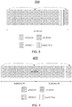
- FIG. 2 illustrates a diagram of radio frame resources (e.g., a resource grid) for a downlink (DL) transmission including a physical downlink control channel (PDCCH) in accordance with an example.
- a radio frame 200 of a signal used to transmit the data can be configured to have a duration, Tf, of 2 milliseconds (ms).
- Tf duration
- Each radio frame can be segmented or divided into ten subframes 210i that are each 0.2 ms long.
- Each subframe can be further subdivided into two slots 220a and 220b, each with a duration, Tslot, of 0.1 ms.
- the first slot (#0) 220a can include a physical downlink control channel (PDCCH) 260 and/or a physical downlink shared channel (PDSCH) 266, and the second slot (#1) 220b can include data transmitted using the PDSCH.
- PDCH physical downlink control channel
- PDSCH physical downlink shared channel
- Each slot for a component carrier (CC) used by the node and the wireless device can include multiple resource blocks (RBs) 230a, 230b, 230i, 230m, and 230n based on the CC frequency bandwidth.
- the CC can include a frequency bandwidth and a center frequency within the frequency bandwidth.
- a subframe of the CC can include downlink control information (DCI) found in the PDCCH.
- DCI downlink control information
- the PDCCH in the control region can include one to three columns of the first OFDM symbols in a subframe or physical RB (PRB), when a legacy PDCCH is used.
- the remaining 11 to 13 OFDM symbols (or 14 OFDM symbols, when legacy PDCCH is not used) in the subframe can be allocated to the PDSCH for data (for short or normal cyclic prefix).
- the term 'slot' may be used for 'subframe', or 'transmission time interval (TTI)' can be used for 'frame' or 'frame duration'.
- a frame may be considered a user transmission specific quantity (such as a TTI associated with a user and a data flow).
- Each RB (physical RB or PRB) 230i can include 12 subcarriers 236 of 15kHz subcarrier spacing, for a total of 180 kHz per RB (on the frequency axis) and 6 or 7 orthogonal frequency-division multiplexing (OFDM) symbols 232 (on the time axis) per slot.
- the RB can use seven OFDM symbols if a short or normal cyclic prefix is employed.
- the RB can use six OFDM symbols if an extended cyclic prefix is used.
- the resource block can be mapped to 84 resource elements (REs) 240i using short or normal cyclic prefixing, or the resource block can be mapped to 72 REs (not shown) using extended cyclic prefixing.
- the RE can be a unit of one OFDM symbol 242 by one subcarrier (i.e., 15 kHz) 246.
- each RE can transmit two bits 250a and 250b of information in the case of quadrature phase-shift keying (QPSK) modulation.
- QPSK quadrature phase-shift keying
- Other types of modulation can be used, such as 16 quadrature amplitude modulation (QAM) or 64 QAM, to transmit 4 bits of information per RE, to transmit 6 bits of information in each RE, or bi-phase shift keying (BPSK) modulation to transmit a lesser number of bits (a single bit) in each RE.
- the RB can be configured for a downlink transmission from the eNodeB to the UE, or the RB can be configured for an uplink transmission from the UE to the eNodeB.
- FIG. 3 an enhanced downlink (DL) self-contained time division duplex (TDD) subframe 300 is depicted. That is, FIG. 3 illustrates a self-contained TDD subframe structure in the DL.
- the xPDSCH can be scheduled by an extended physical downlink control channel (xPDCCH) and can be transmitted immediately after the xPDCCH.
- xPDCCH extended physical downlink control channel
- one or more UEs can feedback the ACK /NACK in an extended physical uplink control channel (xPUCCH) in a selected section of the subframe, such as in the last section (or part) of the subframe.
- a guard time (GT) can be inserted between the xPDSCH and the xPUCCH in order to accommodate the DL-to-UL and/or UL-to-DL switching time and round-trip propagation delay.
- GT guard time
- the round trip propagation delay can be significantly large, and thus the size of GT can also be large.
- two or more subframes can be aggregated for one xPDSCH transmission for one UE, as illustrated in FIG. 4 .
- FIG. 4 depicts a self-contained time division duplex (TDD) subframe aggregation 400 in the downlink (DL).
- the xPDSCH can span two subframes, such as subframe #1 and subframe #2, and a GT can be inserted in the second subframe, such as in between the xPDSCH and the xPUCCH.
- GT overhead can be reduced by half compared to the TDD subframe structure as shown in FIG. 3 .
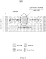
- an eNB may not be able to transmit the xPDSCH and receive the xPUCCH simultaneously, due to a full duplex constraint, as illustrated in FIG. 5 .
- FIG. 5 illustrates 500 an example of potential system issues, such as eNB being able to transmit the xPDSCH and receive the xPUCCH simultaneously, for self-contained time division duplex (TDD) subframes with different aggregation levels.
- the eNB can schedule the xPDSCH transmission for UE #1 in a 1st subframe.
- the eNB can schedule the xPDSCH transmission for UE #3 in both the 1st subframe and a 2nd subframe with an aggregated TDD subframe structure.
- UE #1 may not be able to transmit (Tx) the HARQ ACK/NACK in the 1st subframe given that eNB may not be able to transmit (Tx) and receive (Rx) at the same time.
- an enhanced HARQ-ACK feedback mechanism can be provided.
- the present technology provides for a self-contained TDD subframe structure, with 1) an enhanced self-contained TDD subframe structure, 2) a mechanism to trigger the aggregated TDD subframe, and/or 3) mechanisms to achieve coexistence between self-contained TDD subframes with different aggregation levels within same system bandwidth.
- the guard time can accommodate the DL-to-UL and UL-to-DL switching time and maximum round-trip propagation time. This indicates that the dimension of GT can cover the largest cell size in the deployed scenario.
- an additional signal may be inserted after the data transmission.
- FIG. 6 illustrates enhancements 600 to both a downlink (DL) self-contained time division duplex (TDD) subframe (e.g., an extended DL self-contained TDD subframe) and an uplink (UL) self-contained time division duplex (TDD) subframe (e.g. an extended UL self-contained TDD subframe).
- DL downlink
- UL uplink
- TDD time division duplex
- a spacing signal in the DL, can be inserted after the xPDSCH transmission. That is, in one aspect, an extended self-contained TDD subframe can include a first part including the xPDCCH, the xPDSCH in a second part, the spacing signal in a third part, the guard time (GT) in a fourth part, and xPUCCH in a final or fifth part.
- GT guard time
- the spacing signal can be a broadcast signal, a sounding reference signal (SRS), another type of reference signal (e.g., channel state information reference signal (CSI-RS)), a tracking signal (e.g., beamforming tracking or a time/frequency tracking signal), and/or a DL synchronization signal or synchronization channel (e.g., primary synchronization signal and/or secondary synchronization signal and/or beamforming reference signal).
- SRS sounding reference signal
- CSI-RS channel state information reference signal
- a tracking signal e.g., beamforming tracking or a time/frequency tracking signal
- a DL synchronization signal or synchronization channel e.g., primary synchronization signal and/or secondary synchronization signal and/or beamforming reference signal.
- the placement of the spacing signal in the DL self-contained TDD subframe after the shared channel but prior to the uplink channel, can provide more processing time at the UE to decode the xPDSCH and then determine what, if any data is to be sent in
- a UL spacing signal can be inserted after the extended physical uplink shared channel (xPUSCH) transmission. That is, in one aspect, the UL self-contained TDD subframe may have a first part including the xPDCCH, the guard time (GT) in a second part, the xPUSCH in a third part, an UL spacing signal in a fourth part, and the xPUCCH or xPDCCH in a fifth or final part.
- the UL spacing signal can be a broadcast signal, sounding reference signal (SRS), tracking signal, and/or UL synchronization signal. It should be noted that although in FIG.
- the xPDCCH is illustrated in the last part/section of subframe for the UL self-contained TDD subframe
- xPUCCH can be transmitted in the last part of the subframe and the xPDCCH can be used to carry the UL HARQ ACK/NACK
- the UL HARQ ACK/NACK can be transmitted at a beginning of a first part of a next subframe.
- another dedicated signal e.g., an extended physical HARQ indicator channel (PHICH) can be used to carry the UL HARQ ACK/NACK either in the last part or section of one subframe or the beginning of the next subframe.
- PHICH extended physical HARQ indicator channel
- FIG. 7 illustrates a first example 700 of an enhanced self-contained time division duplex (TDD) subframe 700.
- a self-contained TDD subframe can include one or more fields. That is, the self-contained TDD subframe can have at least five fields.
- the field 701 can be placed first in the self-contained TDD subframe that is used for DL control channel transmission, such as the xPDCCH.
- the second field 702 can be reserved for downlink data transmission, such as the xPDSCH, and a fifth field 705 of subframe 700 can be reserved for UL transmission, such as the xPUCCH, so as to carry HARQ-ACK bits associated with the xPDSCH transmitted in the second field 702.
- a guard time (e.g., a guard period) can be reserved in a third field 703 and can be configured by higher layers with a variable length.
- the duration of the GT can be based on a number of parameters, which may include the maximum round trip propagation time in a cell depending on cell size.
- a spacing signal e.g., a sounding reference signal or other type of signal, as discussed with respect to FIG. 6
- UL data can be transmitted in the field 704 scheduled by the xPDCCH channel 701 in the event the duration of field 702 is too small for the spacing signal (e.g., a SRS) and is not configured.
- FIG. 8 illustrates an example 800 of an enhanced self-contained time division duplex (TDD) subframe with feedback. That is, FIG. 8 illustrates a self-contained TDD subframe that can include five fields with field 800 used for the xPDCCH.
- Field 801 can be used for a first xPDSCH
- field 802 can be used for a second xPDSCH
- field 803 can be used for the guard time (GT)
- field 804 can be used for the xPUCCH for a first HARQ-ACK feedback.
- Fields 800-804 can be used in a first transmission time interval (1xTTI).
- the field 805 can be used for the xPDCCH
- field 806 can be used for a first xPDSCH and field 807 can be used for a second xPDSCH
- field 808 can be used for the guard time (GT)
- field 809 can be used for the xPUCCH.
- Fields 805-809 can be used in a second transmission time interval (1xTTI).
- the length of the TTI can be determined based on system specifications. The TTI length may be fixed, or may vary.
- an additional DL can be introduced within the xPDSCH 802 for additional DL data transmission.
- the differences between xPDSCH 801 and xPDSCH 802 can include the following. 1) Different channel coding and modulation schemes can be applied for two xPDSCHs, such as xPDSCH 801 and xPDSCH 802, in a same transmission time interval (TTI), such as taking into account different processing time for HARQ-ACK feedback (e.g. a higher modulation scheme and/or advanced channel coding scheme such as turbo or tail-biting convolution code (TBCC) encoder can be considered for the latter field 802 compared to field 801).
- TTI transmission time interval
- TBCC tail-biting convolution code
- HARQ-ACK for xPDSCH 801 can be transmitted on field 804 on the xPUCCH channel.
- the HARQ-ACK associated with xPDSCH 802 can be transmitted on xPUCCH 807 in a next TTI due to a processing time limitation.
- the splitting between field 801 and 802 can be fixed in a design specification, configured by higher layers, and/or dynamically indicated by a downlink control information (DCI) format or a combination.
- DCI downlink control information
- the length of field 802 can be variable depending on the length of the GT (e.g., the guard period), e.g. 0 or 1 or 2 or 3 symbols.
- a self-contained TDD subframe can include four fields including xPDSCH 900, xPDCCH 901, GT 902, and/or xPUCCH 903.
- HARQ-ACK feedback e.g., HARQ-ACK bits
- xPDSCH 900 can be carried on xPUCCH 703 in a same subframe (e.g., during a first TTI "1xTTI").
- xPDCCH 901 can be inserted between xPDSCH 900 and its xPUCCH channel 902, which can carry the HARQ-ACK feedback, to schedule the DL data transmission on xPDSCH 904 of the next subframe.
- FIG. 9 also depicts the next or subsequent subframe for a second TTI, with four fields including xPDSCH 904, xPDCCH 905, GT 906, and/or xPUCCH 907. It should be noted that in FIG. 7 , for example, the xPDDCH can be used to schedule the xPDSCH in the same subframe and in FIG. 9 , the xPDCCH can be used to schedule the xPDSCH in a next subframe.
- the present technology provides for triggering and/or indicating when to use an aggregated self-contained TDD subframe.
- an eNB can schedule the DL or UL data transmission within aggregated self-contained TDD subframes.
- one or more options can be considered and employed to trigger the aggregated TDD subframes.
- the number of subframes used for the xPDSCH and/or the xPUSCH transmission within aggregated TDD subframes can be indicated in a DCI format for DL assignment and UL grant.
- the number of subframes used can be explicitly signaled in the DCI format.
- an eNB can indicate a number of subframes from a subset of configured aggregated self-contained TDD subframes, wherein the subset can be predefined and/or configured by higher layers via an extended master information block (xMIB) (e.g., a 3GPP LTE 5G xMIB), an extended system information block (xSIB) (e.g., a 3GPP LTE 5G xSIB), and/or UE specific dedicated RRC signaling.
- xMIB extended master information block
- xSIB extended system information block
- the aggregation level for the aggregated TDD subframes can be ⁇ 1, 2, 4, 8 ⁇ subframes, which can be configured by the xSIB.
- a 2-bit field in the DCI format for DL assignment and UL grant can be used to signal the number of subframes from this subset for the xPDSCH and/or the xPUSCH transmission.
- the number of subframes used for xPDSCH or xPUSCH transmission within aggregated TDD subframes can be indicated via xMIB, xSIB and/or UE dedicated RRC signalling, which it should be noted this can also depend on UE specific capability, i.e., whether a UE can support the aggregated TDD subframe structure.
- the number of subframes used for xPDSCH or xPUSCH transmission can be signaled via a dedicated signal or channel in the DL.
- a legacy Physical Control Format Indicator Channel PCFICH
- PCFICH Physical Control Format Indicator Channel
- 2 bit information can be carried by PCFICH.
- this 2-bit information may indicate that the number of subframes is 1, 2, 4 or 8.
- physical TDD configuration indicator channel PTCICH
- the number of subframes used for the xPDSCH and/or the xPUSCH transmission can be indicated by a combination of the aforementioned mechanisms.
- the set of aggregated levels for the aggregated TDD subframe can be predefined, such as 2, 4, 8, and/or 16 subframes and the PCFICH can be used to indicate one of the aggregation levels in the set.
- cross-subframe scheduling can be used for aggregated TDD subframes.
- a gap between the xPDCCH and the xPDSCH and/or the xPUSCH can be explicitly indicated in the DCI format for DL assignment or UL grant.
- a gap can be provided by higher layer via UE specific dedicated RRC signalling.
- FIG. 10 a system 1000 of cross-subframe scheduling for aggregated self-contained time division duplex (TDD) subframes is depicted. That is, FIG. 10 illustrates one example of cross-subframe scheduling for aggregated TDD subframes.
- the xPDCCH and associated xPDCCH can be transmitted in the same subframe #1, while for UE #2, cross subframe scheduling can be applied (e.g., scheduling xPDSCH using both subrame #2 and subframe #3), where a gap between xPDCCH and associated xPDSCH can be 1 subframe.
- the aggregation levels for UE #1 and #2 can be 1 and 2 subframes, respectively.
- a guard time (GT) (e.g., a guard period) can also be used in between the xPDSCH and the xPUCCH.
- GT guard time
- cross-carrier scheduling can be used for aggregated self-contained TDD subframes.
- a component carrier (CC) index used for the data transmission can be explicitly indicated in the DCI format for DL assignment or UL grant.
- the present technology provides for achieving coexistence between self-contained TDD subframes with different aggregation levels within same system bandwidth.
- an eNB may not be able to transmit the xPDSCH and receive the xPUCCH simultaneously in the case where two or more xPDSCH or xPUSCH transmissions with different aggregation levels are scheduled within the same system bandwidth. To address this issue, several options can be considered.
- aggregated HARQ ACK/NACK mechanisms can be employed for multiple UEs, which are scheduled within the same aggregated TDD subframe window. That is, multiple UEs can transmit the HARQ ACK/NACK in the same subframe. In particular, multiple UEs can feedback the HARQ ACK/NACK via the xPUCCH in a last subframe of the aggregated TDD subframe window. To enable providing the HARQ ACK/NACK feedback via the xPUCCH in a last subframe of the aggregated TDD subframe window, a gap between the xPDSCH and/or the xPUSCH transmission and HARQ ACK/NACK feedback can be explicitly indicated in the DCI format for DL assignment or UL grant.
- FIG. 11 aggregated ACK/NACK feedback for same and cross-subframe scheduling for aggregated self-contained time division duplex (TDD) subframes is depicted. That is, FIG. 11 illustrates examples 1100 of aggregated ACK/NACK feedback for same and cross- subframe scheduling, respectively.
- Option (a) similar and/or same subframe scheduling for the xPDSCH transmissions can be applied for all UEs. Subsequently, all UEs feedback the HARQ ACK/NACK in the same subframe. That is, all UEs feedback the HARQ ACK/NACK in subframe #3 as shown in FIG. 11 .
- a resource index for the ACK/NACK feedback on the xPUCCH can be defined as a UE specific parameter, which can be signaled via UE specific RRC signalling.
- the resource index for the ACK/NACK feedback on the xPUCCH can be determined as a function of subframe index within a maximum aggregation level (which can be specified according to eNB scheduling) and other parameters, such as a demodulation reference signal (DMRS) sequence index for the associated xPDSCH and/or xPUSCH transmission.
- DMRS demodulation reference signal
- cross-carrier ACK/NACK feedback can be enabled to allow coexistence of aggregated self-contained TDD subframes with different aggregation levels, which reduces the latency for HARQ ACK/NACK feedback.
- the CC index for ACK/NACK feedback transmission can be explicitly indicated in the DCI format for DL assignment or UL grant.
- the CC index for ACK/NACK feedback transmission can be signaled via UE specific RRC signalling.
- UE can feedback the ACK/NACK on a primary cell (PCell).
- PCell primary cell
- FIG. 12 illustrates cross-carrier ACK/NACK feedback and self-subframe scheduling for aggregated self-contained time division duplex (TDD) subframes 1200. That is, FIG. 12 illustrates one example of cross-carrier ACK/NACK feedback.
- an eNB can schedule UE #1 to provide ACK/NACK feedback in component carrier (CC) #2, such as within xPUCCH of CC #2.
- CC #1 component carrier
- UE #2 and #3 can feedback the aggregated ACK/NACK in the same subframe, such as within xPUCCH of subframe #2.
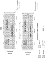
- FIG. 13 illustrates cross-carrier ACK/NACK feedback and cross-subframe scheduling for aggregated self-contained time division duplex (TDD) subframes 1300 in accordance with an example.
- cross-subframe scheduling can be applied for UE#2 and the starting position of xPDSCH transmission for UE #2 can be right after the xPDSCH transmission for UE #1.
- the GT in the CC# as shown above in FIG. 12 , can be avoided, thereby improving the spectrum efficiency.
- a resource index for the ACK/NACK feedback on the xPUCCH can be defined as a UE specific parameter, which can be signaled via UE specific radio resources control (RRC) signalling.
- RRC radio resources control
- a resource index for the ACK/NACK feedback on the xPUCCH can be determined as a function of CC index for the data transmission and other parameters, such as the DMRS sequence index for the associated xPDSCH or xPUSCH transmission.
- an example provides functionality 1400 of an eNodeB operable to communicate with a User Equipment (UE) using a self-contained time division duplex (TDD) subframe, as shown in the flow chart in FIG. 14 .
- the functionality 1400 can be implemented as a method or the functionality can be executed as instructions on a machine, where the instructions are included one or more computer readable mediums or one or more non-transitory machine readable storage mediums.
- the eNodeB can comprise one or more processors and memory configured to: generate and/or process, for transmission to the UE, a DL self-contained time division duplex (TDD) subframe comprising an extended physical downlink shared channel (xPDSCH), an extended physical downlink control channel (xPDCCH), a downlink (DL) spacing signal, and a guard time, wherein the xPDSCH, the xPDCCH, the DL spacing signal, and the guard time are located within the DL self-contained TDD subframe prior to an extended physical uplink control channel (xPUCCH), as in block 1410.
- TDD time division duplex
- the eNodeB can comprise one or more processors and memory configured to: process, an uplink (UL) self-contained TDD subframe, received from the UE, having a UL spacing signal located after an extended physical uplink shared channel (xPUSCH), as in block 1420.
- UL uplink
- xPUSCH extended physical uplink shared channel
- FIG. 15 Another example provides functionality 1500 of a user equipment (UE) operable to communicate with an eNodeB using a self-contained time division duplex (TDD) subframe, as shown in the flow chart in FIG. 15 .
- the functionality 1500 can be implemented as a method or the functionality can be executed as instructions on a machine, where the instructions are included one or more computer readable mediums or one or more non-transitory machine readable storage mediums.
- the UE can comprise one or more processors and memory configured to: process a DL self-contained time division duplex (TDD) subframe, received from the eNodeB, comprising an extended physical downlink shared channel (xPDSCH), an extended physical downlink control channel (xPDCCH), a downlink (DL) spacing signal, and a guard time, wherein the xPDSCH, the xPDCCH, the DL spacing signal, and the guard time are located within the DL self-contained TDD subframe prior to an extended physical uplink control channel (xPUCCH), as in block 1510.
- TDD time division duplex
- the UE can comprise one or more processors and memory configured to: generate and/or process, for transmission to the eNodeB, an uplink (UL) self-contained TDD subframe an extended physical uplink shared channel (xPUSCH) having an UL spacing signal located after an extended physical uplink shared channel (xPUSCH), as in block 1520.
- UL uplink
- xPUSCH extended physical uplink shared channel
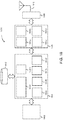
- Another example provides functionality 1600 of an eNodeB operable to communicate with a User Equipment (UE) using a self-contained time division duplex (TDD) subframe, as shown in the flow chart in FIG. 16 .
- the functionality 1600 can be implemented as a method or the functionality can be executed as instructions on a machine, where the instructions are included one or more computer readable mediums or one or more non-transitory machine readable storage mediums.
- the eNodeB can comprise one or more processors and memory configured to: generate and/or process, for transmission to the UE, a DL self-contained time division duplex (TDD) subframe comprising an extended physical downlink shared channel (xPDSCH), an extended physical downlink control channel (xPDCCH), a downlink (DL) spacing signal, and a guard time (e.g., guard period), wherein the xPDSCH, the xPDCCH, the DL spacing signal, and the guard time are located within the DL self-contained TDD subframe prior to an extended physical uplink control channel (xPUCCH), as in block 1610.
- TDD time division duplex
- the eNodeB can comprise one or more processors and memory configured to: process, an uplink (UL) self-contained TDD subframe, received from the UE, having a UL spacing signal located after an extended physical uplink shared channel (xPUSCH), as in block 1620.
- the eNodeB can comprise one or more processors and memory configured to: schedule DL data transmission and UL data transmission using aggregated self-contained TDD subframes upon data transmission traffic exceeding a defined threshold, as in block 1630.
- the eNodeB can comprise one or more processors and memory configured to: process, for transmission to the UE, an indication for using the aggregated self-contained TDD subframes, as in block 1640.
- FIG. 17 illustrates a diagram of a wireless device (e.g., UE) in accordance with an example.
- FIG. 17 provides an example illustration of the wireless device, such as a user equipment (UE) UE, a mobile station (MS), a mobile wireless device, a mobile communication device, a tablet, a handset, or other type of wireless device.
- the wireless device can include at least one of an antenna, a touch sensitive display screen, a speaker, a microphone, a graphics processor, a baseband processor, an application processor, internal memory, a non-volatile memory port, and combinations thereof.
- the wireless device can include one or more antennas configured to communicate with a node or transmission station, such as a base station (BS), an evolved Node B (eNB), a baseband unit (BBU), a remote radio head (RRH), a remote radio equipment (RRE), a relay station (RS), a radio equipment (RE), a remote radio unit (RRU), a central processing module (CPM), or other type of wireless wide area network (WWAN) access point.
- the wireless device can be configured to communicate using at least one wireless communication standard including 3GPP LTE, WiMAX, High Speed Packet Access (HSPA), Bluetooth, and WiFi.
- the wireless device can communicate using separate antennas for each wireless communication standard or shared antennas for multiple wireless communication standards.
- the wireless device can communicate in a wireless local area network (WLAN), a wireless personal area network (WPAN), and/or a WWAN.
- the mobile device can include a storage medium.
- the storage medium can be associated with and/or communicate with the application processor, the graphics processor, the display, the non-volatile memory port, and/or internal memory.
- the application processor and graphics processor are storage mediums.
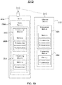
- FIG. 18 illustrates a diagram of example components of a User Equipment (UE) device in accordance with an example.
- Fig. 18 illustrates, for one aspect, example components of a User Equipment (UE) device 1800.
- the UE device 1800 can include application circuitry 1802, baseband circuitry 1804, Radio Frequency (RF) circuitry 1806, front-end module (FEM) circuitry 1808 and one or more antennas 1810, coupled together at least as shown.
- RF Radio Frequency
- FEM front-end module
- the application circuitry 1802 can include one or more application processors.
- the application circuitry 1802 can include circuitry such as, but not limited to, one or more single-core or multi-core processors.
- the processor(s) can include any combination of general-purpose processors and dedicated processors (e.g., graphics processors, application processors, etc.).
- the processors can be coupled with and/or can include memory/storage and can be configured to execute instructions stored in the memory/storage to enable various applications and/or operating systems to run on the system.
- the processor(s) can include any combination of general-purpose processors and dedicated processors (e.g., graphics processors, application processors, etc.).
- the processors can be coupled with and/or can include a storage medium 1812, and can be configured to execute instructions stored in the storage medium 1812 to enable various applications and/or operating systems to run on the system.
- the baseband circuitry 1804 can include circuitry such as, but not limited to, one or more single-core or multi-core processors.
- the baseband circuitry 1804 can include one or more baseband processors and/or control logic to process baseband signals received from a receive signal path of the RF circuitry 1806 and to generate baseband signals for a transmit signal path of the RF circuitry 1806.
- Baseband processing circuitry 1804 can interface with the application circuitry 1802 for generation and processing of the baseband signals and for controlling operations of the RF circuitry 1806.
- the baseband circuitry 1804 can include a second generation (2G) baseband processor 1804a, third generation (3G) baseband processor 1804b, fourth generation (4G) baseband processor 1804c, and/or other baseband processor(s) 1804d for other existing generations, generations in development or to be developed in the future (e.g., fifth generation (5G), 6G, etc.).
- the baseband circuitry 1804 e.g., one or more of baseband processors 1804a-d
- the radio control functions can include, but are not limited to, signal modulation/demodulation, encoding/decoding, radio frequency shifting, etc.
- modulation/demodulation circuitry of the baseband circuitry 1804 can include Fast-Fourier Transform (FFT), precoding, and/or constellation mapping/demapping functionality.
- FFT Fast-Fourier Transform
- encoding/decoding circuitry of the baseband circuitry 1804 can include convolution, tail-biting convolution, turbo, Viterbi, and/or Low Density Parity Check (LDPC) encoder/decoder functionality.
- LDPC Low Density Parity Check
- the baseband circuitry 1804 can include elements of a protocol stack such as, for example, elements of an evolved universal terrestrial radio access network (EUTRAN) protocol including, for example, physical (PHY), media access control (MAC), radio link control (RLC), packet data convergence protocol (PDCP), and/or radio resource control (RRC) elements.
- EUTRAN evolved universal terrestrial radio access network
- a central processing unit (CPU) 1804e of the baseband circuitry 1804 can be configured to run elements of the protocol stack for signaling of the PHY, MAC, RLC, PDCP and/or RRC layers.
- the baseband circuitry can include one or more audio digital signal processor(s) (DSP) 1804f.
- DSP audio digital signal processor
- the audio DSP(s) 1804f can be include elements for compression/decompression and echo cancellation and can include other suitable processing elements in other aspects.
- Components of the baseband circuitry can be suitably combined in a single chip, a single chipset, or disposed on a same circuit board in some aspects.
- some or all of the constituent components of the baseband circuitry 1804 and the application circuitry 1802 can be implemented together such as, for example, on a system on a chip (SOC).
- SOC system on a chip
- the baseband circuitry 1804 can provide for communication compatible with one or more radio technologies.
- the baseband circuitry 1804 can support communication with an evolved universal terrestrial radio access network (EUTRAN) and/or other wireless metropolitan area networks (WMAN), a wireless local area network (WLAN), a wireless personal area network (WPAN).
- EUTRAN evolved universal terrestrial radio access network
- WMAN wireless metropolitan area networks
- WLAN wireless local area network
- WPAN wireless personal area network
- RF circuitry 1806 can enable communication with wireless networks using modulated electromagnetic radiation through a non-solid medium.
- the RF circuitry 1806 can include switches, filters, amplifiers, etc. to facilitate the communication with the wireless network.
- RF circuitry 1806 can include a receive signal path which can include circuitry to down-convert RF signals received from the FEM circuitry 1808 and provide baseband signals to the baseband circuitry 1804.
- RF circuitry 1806 can also include a transmit signal path which can include circuitry to up-convert baseband signals provided by the baseband circuitry 1804 and provide RF output signals to the FEM circuitry 1808 for transmission.
- the RF circuitry 1806 can include a receive signal path and a transmit signal path.
- the receive signal path of the RF circuitry 1806 can include mixer circuitry 1806a, amplifier circuitry 1806b and filter circuitry 1806c.
- the transmit signal path of the RF circuitry 1806 can include filter circuitry 1806c and mixer circuitry 1806a.
- RF circuitry 1806 can also include synthesizer circuitry 1806d for synthesizing a frequency for use by the mixer circuitry 1806a of the receive signal path and the transmit signal path.
- the mixer circuitry 1806a of the receive signal path can be configured to down-convert RF signals received from the FEM circuitry 1808 based on the synthesized frequency provided by synthesizer circuitry 1806d.
- the amplifier circuitry 1806b can be configured to amplify the down-converted signals and the filter circuitry 1806c can be a low-pass filter (LPF) or band-pass filter (BPF) configured to remove unwanted signals from the down-converted signals to generate output baseband signals.
- Output baseband signals can be provided to the baseband circuitry 1804 for further processing.
- the output baseband signals can be zero-frequency baseband signals, although the output baseband signals do not have to be zero-frequency baseband signals.
- mixer circuitry 1806a of the receive signal path can comprise passive mixers, although the scope of the aspects is not limited in this respect.
- the mixer circuitry 1806a of the transmit signal path can be configured to up-convert input baseband signals based on the synthesized frequency provided by the synthesizer circuitry 1806d to generate RF output signals for the FEM circuitry 1808.
- the baseband signals can be provided by the baseband circuitry 1804 and can be filtered by filter circuitry 1806c.
- the filter circuitry 1806c can include a low-pass filter (LPF), although the scope of the aspects is not limited in this respect.
- the mixer circuitry 1806a of the receive signal path and the mixer circuitry 1806a of the transmit signal path can include two or more mixers and can be arranged for quadrature downconversion and/or upconversion respectively.
- the mixer circuitry 1806a of the receive signal path and the mixer circuitry 1806a of the transmit signal path can include two or more mixers and can be arranged for image rejection (e.g., Hartley image rejection).
- the mixer circuitry 1806a of the receive signal path and the mixer circuitry 1806a can be arranged for direct downconversion and/or direct upconversion, respectively.
- the mixer circuitry 1806a of the receive signal path and the mixer circuitry 1806a of the transmit signal path can be configured for super-heterodyne operation.
- the output baseband signals and the input baseband signals can be analog baseband signals, although the scope of the aspects is not limited in this respect.
- the output baseband signals and the input baseband signals can be digital baseband signals.
- the RF circuitry 1806 can include analog-to-digital converter (ADC) and digital-to-analog converter (DAC) circuitry and the baseband circuitry 1804 can include a digital baseband interface to communicate with the RF circuitry 1806.
- ADC analog-to-digital converter
- DAC digital-to-analog converter
- a separate radio IC circuitry can be provided for processing signals for each spectrum, although the scope of the embodiments is not limited in this respect.
- the synthesizer circuitry 1806d can be a fractional-N synthesizer or a fractional N/N+1 synthesizer, although the scope of the embodiments is not limited in this respect as other types of frequency synthesizers can be suitable.
- synthesizer circuitry 1806d can be a delta-sigma synthesizer, a frequency multiplier, or a synthesizer comprising a phase-locked loop with a frequency divider.
- the synthesizer circuitry 1806d can be configured to synthesize an output frequency for use by the mixer circuitry 1806a of the RF circuitry 1806 based on a frequency input and a divider control input.
- the synthesizer circuitry 1806d can be a fractional N/N+1 synthesizer.
- frequency input can be provided by a voltage controlled oscillator (VCO), although that is not a constraint.
- VCO voltage controlled oscillator
- Divider control input can be provided by either the baseband circuitry 1804 or the applications processor 1802 depending on the desired output frequency.
- a divider control input e.g., N
- N can be determined from a look-up table based on a channel indicated by the applications processor 1802.
- Synthesizer circuitry 1806d of the RF circuitry 1806 can include a divider, a delay-locked loop (DLL), a multiplexer and a phase accumulator.
- the divider can be a dual modulus divider (DMD) and the phase accumulator can be a digital phase accumulator (DPA).
- the DMD can be configured to divide the input signal by either N or N+1 (e.g., based on a carry out) to provide a fractional division ratio.
- the DLL can include a set of cascaded, tunable, delay elements, a phase detector, a charge pump and a D-type flip-flop.
- the delay elements can be configured to break a VCO period up into Nd equal packets of phase, where Nd is the number of delay elements in the delay line.
- Nd is the number of delay elements in the delay line.
- synthesizer circuitry 1806d can be configured to generate a carrier frequency as the output frequency, while in other embodiments, the output frequency can be a multiple of the carrier frequency (e.g., twice the carrier frequency, four times the carrier frequency) and used in conjunction with quadrature generator and divider circuitry to generate multiple signals at the carrier frequency with multiple different phases with respect to each other.
- the output frequency can be a LO frequency (fLO).
- the RF circuitry 1806 can include an IQ/polar converter.
- FEM circuitry 1808 can include a receive signal path which can include circuitry configured to operate on RF signals received from one or more antennas 1810, amplify the received signals and provide the amplified versions of the received signals to the RF circuitry 1806 for further processing.
- FEM circuitry 1808 can also include a transmit signal path which can include circuitry configured to amplify signals for transmission provided by the RF circuitry 1806 for transmission by one or more of the one or more antennas 1810.
- the FEM circuitry 1808 can include a TX/RX switch to switch between transmit mode and receive mode operation.
- the FEM circuitry can include a receive signal path and a transmit signal path.
- the receive signal path of the FEM circuitry can include a low-noise amplifier (LNA) to amplify received RF signals and provide the amplified received RF signals as an output (e.g., to the RF circuitry 1806).
- the transmit signal path of the FEM circuitry 1808 can include a power amplifier (PA) to amplify input RF signals (e.g., provided by RF circuitry 1806), and one or more filters to generate RF signals for subsequent transmission (e.g., by one or more of the one or more antennas 1810.
- PA power amplifier
- the UE device 1800 can include additional elements such as, for example, memory/storage, display, camera, sensor, and/or input/output (I/O) interface.
- additional elements such as, for example, memory/storage, display, camera, sensor, and/or input/output (I/O) interface.
- FIG. 19 illustrates a diagram 1900 of a node 1910 (e.g., eNB and/or a base station) and wireless device (e.g., UE) in accordance with an example.
- the node can include a base station (BS), a Node B (NB), an evolved Node B (eNB), a baseband unit (BBU), a remote radio head (RRH), a remote radio equipment (RRE), a remote radio unit (RRU), or a central processing module (CPM).
- the node can be a Serving GPRS Support Node.
- the node 1910 can include a node device 1912.
- the node device 1912 or the node 1910 can be configured to communicate with the wireless device 1920.
- the node device 1912 can be configured to implement the technology described.
- the node device 1912 can include a processing module 1914 and a transceiver module 1916.
- the node device 1912 can include the transceiver module 1916 and the processing module 1914 forming a circuitry 1918 for the node 1910.
- the transceiver module 1916 and the processing module 1914 can form a circuitry of the node device 1912.
- the processing module 1914 can include one or more processors and memory.
- the processing module 1922 can include one or more application processors.
- the transceiver module 1916 can include a transceiver and one or more processors and memory.
- the transceiver module 1916 can include a baseband processor.
- the wireless device 1920 can include a transceiver module 1924 and a processing module 1922.
- the processing module 1922 can include one or more processors and memory. In one embodiment, the processing module 1922 can include one or more application processors.
- the transceiver module 1924 can include a transceiver and one or more processors and memory. In one embodiment, the transceiver module 1924 can include a baseband processor.
- the wireless device 1920 can be configured to implement the technology described.
- the node 1910 and the wireless devices 1920 can also include one or more storage mediums, such as the transceiver module 1916, 1924 and/or the processing module 1914, 1922. In one aspect, the components described herein of the transceiver module 1916 can be included in one or more separate devices that may used in a cloud-RAN (C-RAN) environment.
- C-RAN cloud-RAN
- Example 1 includes an apparatus of an eNodeB, the eNodeB configured to communicate with a User Equipment (UE), the apparatus comprising one or more processors and memory configured to: generate, for transmission to the UE, a downlink (DL) self-contained time division duplex (TDD) subframe comprising an extended physical downlink shared channel (xPDSCH), an extended physical downlink control channel (xPDCCH), a DL spacing signal, and a guard period, wherein the xPDSCH, the xPDCCH, the DL spacing signal, and the guard period are located within the DL self-contained TDD subframe prior to an extended physical uplink control channel (xPUCCH); and process, an uplink (UL) self-contained TDD subframe, received from the UE, having a UL spacing signal located before after an extended physical uplink shared channel (xPUSCH).
- TDD time division duplex
- Example 2 includes the apparatus of example 1, wherein the DL spacing signal is at least one of a broadcast signal, a sounding signal, a tracking signal, or a synchronization signal, and the UL spacing signal is at least one of the broadcast signal, the sounding signal, the tracking signal, or the synchronization signal.
- the DL spacing signal is at least one of a broadcast signal, a sounding signal, a tracking signal, or a synchronization signal
- the UL spacing signal is at least one of the broadcast signal, the sounding signal, the tracking signal, or the synchronization signal.
- Example 3 includes the apparatus of example 1 or 2, wherein the one or more processors and memory are further configured to: schedule DL data transmission and UL data transmission using aggregated self-contained TDD subframes; or process, for transmission to the UE, an indication for using the aggregated self-contained TDD subframes.
- Example 4 includes the apparatus of example 1, wherein the DL spacing signal is inserted within the DL self-contained TDD subframe after the xPDSCH and prior to the guard period.
- Example 5 includes the apparatus of example 1, wherein the DL self-contained TDD subframe contains one or more fields.
- Example 6 includes the apparatus of example 1 or 5, wherein the one or more fields include at least: the xPDCCH, the xPDSCH, the guard period; the UL spacing signal, and the xPUCCH; the xPDCCH, a first xPDSCH, a second xPDSCH, the guard period, and the xPUCCH; or the xPDSCH, the xPDCCH, the guard period, and the xPUCCH, wherein the xPDCCH is used to schedule the xPDSCH in a second DL self-contained TDD subframe.
- the one or more fields include at least: the xPDCCH, the xPDSCH, the guard period; the UL spacing signal, and the xPUCCH; the xPDCCH, a first xPDSCH, a second xPDSCH, the guard period, and the xPUCCH; or the xPDSCH, the xPDCCH, the guard period, and the xPUCCH, wherein the xPD
- Example 7 includes the apparatus of example 1 , wherein the one or more processors and memory are further configured to: perform different channel coding and modulation schemes; separate a cyclic redundancy check (CRC) attachment and the first xPDSCH and the second xPDSCH contained within the second DL self-contained TDD subframe; process, for transmission to the UE, a hybrid automatic repeat request (HARQ)-acknowledgment (ACK) (HARQ-ACK) for the xPDSCH transmitted via the xPUCCH; or process, for transmission to the UE, a first HARQ-ACK for the first xPDSCH transmitted via the xPUCCH in a first subframe and a second HARQ-ACK for the second xPDSCH via the xPUCCH in a second DL self-contained TDD subframe.
- CRC cyclic redundancy check
- Example 8 includes the apparatus of example 1 or 2, wherein a number of self-contained TDD subframes used for the xPDSCH or the xPUSCH for data transmissions within the aggregated self-contained TDD subframes are indicated in the DCI format for the DL assignment and the UL grant.
- Example 9 includes the apparatus of example 1 or 8, wherein the number of self-contained TDD subframes within the aggregated self-contained TDD subframes are defined within one subset of the aggregated self-contained TDD subframes, wherein the subset is predefined or configured by higher layers via an extended master information block (xMIB), an extended system information block (xSIB), or a UE specific dedicated radio resource control (RRC) signalling.
- xMIB extended master information block
- xSIB extended system information block
- RRC radio resource control
- Example 10 includes the apparatus of example 1, wherein a number of self-contained TDD subframes used for the xPDSCH or the xPUSCH data transmission within the aggregated self-contained TDD subframes are indicated via the extended xMIB, the extended xSIB, or a UE dedicated RRC signalling.
- Example 11 includes the apparatus of example 1 or 10, wherein the number of self-contained TDD subframes used for the xPDSCH or the xPUSCH transmission is signaled via a dedicated signal or a channel in the DL data transmission.
- Example 12 includes the apparatus of example 1, wherein the one or more processors and memory are further configured to: reuse a Physical Control Format Indicator Channel (PCFICH) (e.g., a3GPP long-term evolution (LTE) Rel. 12 Physical Control Format Indicator Channel (PCFICH)) to indicate a number of self-contained TDD subframes; use a physical TDD configuration indicator channel (PTCICH) to indicate the number of self-contained TDD subframes; or use a downlink control information (DCI) format, the xMIB, the xSIB, the UE dedicated RRC signalling, a dedicated signal or a channel in the DL data transmission, or a combination thereof to indicate a number of self-contained TDD subframes.
- PCFICH Physical Control Format Indicator Channel
- PTCICH physical TDD configuration indicator channel
- DCI downlink control information
- Example 13 includes the apparatus of example 1 or 12, wherein the one or more processors and memory are further configured to: predefine a subset of aggregated levels for the aggregated self-contained TDD subframes; use the PCFICH to indicate one of the aggregation levels in the subset; use cross-subframe scheduling and cross-carrier scheduling to schedule the xPDSCH or the xPUSCH for the aggregated self-contained TDD subframes; or employ an aggregated Hybrid automatic repeat request (HARQ) acknowledgement (ACK)/negative ACK (ACK/NACK) mechanism for one or more UEs scheduled within an aggregated self-contained TDD subframe window; wherein the one or more UEs feedback the HARQ ACK/NACK via the xPUCCH in a last subframe of the aggregated self-contained TDD subframe window, wherein a gap between the xPDSCH or the xPUSCH data transmission and HARQ ACK/NACK feedback is indicated in a downlink control information (DCI) format for a
- Example 14 includes the apparatus of example 1, wherein a resource index for the HARQ ACK/NACK feedback on the xPUCCH is defined as a UE specific parameter, which is signaled via a UE specific RRC signalling, or the resource index for the HARQ ACK/NACK feedback on the xPUCCH is determined as a function of a subframe index within a maximum aggregation level and one or more parameters that include at least a De-Modulation Reference Signal (DM-RS) sequence index for an associated xPDSCH transmission or xPUSCH transmission.
- DM-RS De-Modulation Reference Signal
- Example 15 includes the apparatus of example 1 or 14, wherein the one or more processors and memory are further configured to: use cross-carrier HARQ ACK/NACK feedback; use a component carrier (CC) index for the HARQ ACK/NACK feedback transmission which is explicitly indicated in the DCI format for DL assignment or UL grant; or use a UE specific RRC signalling, wherein a resource index for the HARQ ACK/NACK feedback on the xPUCCH is defined as a UE specific parameter which is signaled via the UE specific RRC signalling or determined as a function of the CC index for the data transmission and one or more parameters, that include at least a De-Modulation Reference Signal (DM-RS) sequence index for the associated xPDSCH transmission or xPUSCH transmission.
- DM-RS De-Modulation Reference Signal
- Example 16 includes an apparatus of a user equipment (UE), the UE configured to communicate with an eNodeB, the apparatus comprising one or more processors and memory configured to: process a downlink (DL) self-contained time division duplex (TDD) subframe, received from the eNodeB, comprising an extended physical downlink shared channel (xPDSCH), an extended physical downlink control channel (xPDCCH), a DL spacing signal, and a guard period, wherein the xPDSCH, the xPDCCH, the DL spacing signal, and the guard period are located within the DL self-contained TDD subframe prior to an extended physical uplink control channel (xPUCCH); and generate, for transmission to the eNodeB, an uplink (UL) self-contained TDD subframe after an extended physical uplink shared channel (xPUSCH) having an UL spacing signal located before or after the xPUSCH.
- DL downlink
- xPDSCH extended physical downlink shared channel
- xPDCCH extended physical downlink control channel
- Example 17 includes the apparatus of example 16, wherein the one or more processors and memory are further configured to process an indication, received from the eNodeB, for using aggregated self-contained TDD subframes.
- Example 18 includes the apparatus of example 16 or 17, wherein the DL spacing signal is at least one of a broadcast signal, a sounding signal, a tracking signal, or a synchronization signal, and the UL spacing signal is at least one of the broadcast signal, the sounding signal, the tracking signal, or the synchronization signal, and wherein the DL spacing signal is inserted within the DL self-contained TDD subframe after the xPDSCH and prior to the guard period.
- the DL spacing signal is at least one of a broadcast signal, a sounding signal, a tracking signal, or a synchronization signal
- the UL spacing signal is at least one of the broadcast signal, the sounding signal, the tracking signal, or the synchronization signal
- Example 19 includes the apparatus of example 16 or 18, wherein the DL self-contained TDD subframe contains one or more fields, the one or more fields include at least: the xPDCCH, the xPDSCH, the guard period; the UL spacing signal, and the xPUCCH; the xPDCCH, a first xPDSCH, a second xPDSCH, the guard period, and the xPUCCH; or the xPDSCH, the xPDCCH, the guard period, and the xPUCCH, wherein the xPDCCH is used to schedule the xPDSCH in a second DL self-contained TDD subframe.
- the xPDCCH is used to schedule the xPDSCH in a second DL self-contained TDD subframe.
- Example 20 includes the apparatus of example 16, wherein the one or more processors and memory are further configured to: process a hybrid automatic repeat request (HARQ)-acknowledgment (ACK) (HARQ-ACK) for the xPDSCH transmitted via the xPUCCH; or process a first HARQ-ACK for the first xPDSCH transmitted via the xPUCCH in a first subframe and a second HARQ-ACK for the second xPDSCH via the xPUCCH in a second DL self-contained TDD subframe.
- HARQ hybrid automatic repeat request
- Example 21 includes the apparatus of example 16, wherein: a number of self-contained TDD subframes used for the xPDSCH or the xPUSCH for data transmissions within the aggregated self-contained TDD subframes are indicated in the DCI format for the DL assignment and the UL grant; the number of self-contained TDD subframes within the aggregated self-contained TDD subframes are defined within one subset of the aggregated self-contained TDD subframes, wherein the subset is predefined or configured by higher layers via an extended master information block (xMIB), an extended system information block (xSIB), or a UE specific dedicated radio resource control (RRC) signalling; the number of self-contained TDD subframes used for the xPDSCH or the xPUSCH data transmission within the aggregated self-contained TDD subframes are indicated via the extended xMIB, the extended xSIB, or the UE dedicated RRC signalling; the number of self-contained TDD subframes used for the x
- PCFICH Physical Control Format Indicator Channel
- PTCICH physical TDD configuration indicator channel
- DCI format, the extended xMIB, the extended xSIB, a UE dedicated RRC signalling, the dedicated signal or the channel in the DL data transmission, or a combination thereof indicates the number of self-contained TDD subframes.
- Example 22 includes the apparatus of example 16 or 21, wherein: a subset of aggregated levels for the aggregated self-contained TDD subframes is predefined; the PCFICH indicates one of the aggregation levels in the subset; the xPDSCH and the xPUSCH for the aggregated self-contained TDD subframes is scheduled using cross-subframe scheduling, cross-carrier scheduling, or a combination thereof; or an aggregated Hybrid automatic repeat request (HARQ) acknowledgement (ACK)/negative ACK (NACK) mechanism is used for the UE and one or more additional UEs scheduled within an aggregated self-contained TDD subframe window; wherein the UE and the one or more one or more additional UEs each feedback the HARQ ACK/NACK via the xPUCCH in a last subframe of the aggregated self-contained TDD subframe window, wherein a gap between the xPDSCH or the xPUSCH data transmission and the HARQ ACK/NACK feedback is indicated in a DCI format for a
- Example 23 includes the apparatus of example 16, wherein a resource index for the HARQ ACK/NACK feedback on the xPUCCH is defined as a UE specific parameter, which is signaled via a UE specific RRC signalling, or the resource index for the HARQ ACK/NACK feedback on the xPUCCH is determined as a function of a subframe index within a maximum aggregation level and one or more parameters including at least a De-Modulation Reference Signal (DM-RS) sequence index for an associated xPDSCH transmission or xPUSCH transmission.
- DM-RS De-Modulation Reference Signal
- Example 24 includes the apparatus of example 16 or 23, wherein the one or more processors and memory are further configured to: use a cross-carrier for providing HARQ ACK/NACK feedback; use a component carrier (CC) index for providing the HARQ ACK/NACK feedback indicated in the DCI format for DL assignment or UL grant, wherein a resource index for the HARQ ACK/NACK feedback on the xPUCCH is defined as a UE specific parameter which is signaled via the UE specific RRC signalling or determined as a function of the CC index for the data transmission and one or more parameters including at least a De-Modulation Reference Signal (DM-RS) sequence index for the associated xPDSCH transmission or the xPUSCH transmission.
- DM-RS De-Modulation Reference Signal
- Example 25 includes the apparatus of example 16, wherein the apparatus includes at least one of an antenna, a touch sensitive display screen, a speaker, a microphone, a graphics processor, an application processor, a baseband processor, an internal memory, a non-volatile memory port, and combinations thereof.
- Example 26 includes at least one machine readable storage medium having instructions embodied thereon for an eNodeB to communicate with a User Equipment (UE), the instructions when executed cause the eNodeB to: generate, for transmission to the UE, a downlink (DL) self-contained time division duplex (TDD) subframe comprising an extended physical downlink shared channel (xPDSCH), an extended physical downlink control channel (xPDCCH), a DL spacing signal, and a guard period, wherein the xPDSCH, the xPDCCH, the DL spacing signal, and the guard period are located within the DL self-contained TDD subframe prior to an extended physical uplink control channel (xPUCCH); process, an uplink (UL) self-contained TDD subframe, received from the UE, having a UL spacing signal located before or after a extended physical uplink shared channel (xPUSCH); schedule DL data transmission and UL data transmission using aggregated self-contained TDD subframes; and process, for transmission to the UE, an indication
- Example 27 includes the at least one machine readable storage medium of example 26, wherein the plurality of signal types include at least a downlink (DL) sounding reference signal (SRS), channel state information reference signal (CSI-RS), a broadcast signal, and a synchronization signal.
- DL downlink
- SRS sounding reference signal
- CSI-RS channel state information reference signal
- broadcast signal a broadcast signal
- synchronization signal a synchronization signal
- Example 28 includes the at least one machine readable storage medium of example 26 or 27, further comprising instructions which when executed cause the eNodeB to: separate a cyclic redundancy check (CRC) attachment an the first xPDSCH and the second xPDSCH within a same DL self-contained TDD subframe; process, for transmission to the UE, a hybrid automatic repeat request (HARQ)-acknowledgment (ACK) (HARQ-ACK) for the xPDSCH; use Physical Control Format Indicator Channel (PCFICH) (e.g., a 3GPP long term evolution (LTE) Rel.
- CRC cyclic redundancy check
- ACK hybrid automatic repeat request
- PCFICH Physical Control Format Indicator Channel
- PCFICH Physical Control Format Indicator Channel
- PTCICH physical TDD configuration indicator channel
- RRC radio resource control
- Example 29 includes the at least one machine readable storage medium of example 26, further comprising instructions which when executed cause the eNodeB to: use cross-subframe scheduling and/or cross-carrier scheduling to schedule the xPDSCH and the xPUSCH for the aggregated self-contained TDD subframes; or employ an aggregated Hybrid automatic repeat request (HARQ) acknowledgement (ACK)/negative ACK (NACK) mechanism for one or more UEs scheduled within an aggregated self-contained TDD subframe window, wherein the one or more UEs feedback the HARQ ACK/NACK via the xPUCCH in a last subframe of the aggregated self-contained TDD subframe window, wherein a gap between the xPDSCH or the xPUSCH data transmission and HARQ ACK/NACK feedback is indicated in the DCI format for the DL assignment or the UL grant.
- HARQ Hybrid automatic repeat request
- NACK negative ACK
- Example 30 includes the at least one machine readable storage medium of example 26 or 29, further comprising instructions which when executed cause the eNodeB to: use cross-carrier HARQ ACK/NACK feedback; or use a component carrier (CC) index for the HARQ ACK/NACK feedback transmission is explicitly indicated in the DCI format for DL assignment or UL grant, wherein a resource index for the HARQ ACK/NACK feedback on the xPUCCH is defined as a UE specific parameter which is signaled via the UE specific RRC signalling or determined as a function of the CC index for the data transmission and one or more parameters including De-Modulation Reference Signal (DM-RS) sequence index for the associated xPDSCH or xPUSCH transmission.
- DM-RS De-Modulation Reference Signal
- Example 31 includes an apparatus of an eNodeB, the eNodeB configured to communicate with a User Equipment (UE), the apparatus comprising one or more processors and memory configured to: generate, for transmission to the UE, a downlink (DL) self-contained time division duplex (TDD) subframe comprising an extended physical downlink shared channel (xPDSCH), an extended physical downlink control channel (xPDCCH), a DL spacing signal, and a guard period, wherein the xPDSCH, the xPDCCH, the DL spacing signal, and the guard period are located within the DL self-contained TDD subframe prior to an extended physical uplink control channel (xPUCCH); and process, an uplink (UL) self-contained TDD subframe, received from the UE, having a UL spacing signal located before after an extended physical uplink shared channel (xPUSCH).
- TDD time division duplex
- Example 32 includes the apparatus of example 31, wherein the DL spacing signal is at least one of a broadcast signal, a sounding signal, a tracking signal, or a synchronization signal, and the UL spacing signal is at least one of the broadcast signal, the sounding signal, the tracking signal, or the synchronization signal.
- the DL spacing signal is at least one of a broadcast signal, a sounding signal, a tracking signal, or a synchronization signal
- the UL spacing signal is at least one of the broadcast signal, the sounding signal, the tracking signal, or the synchronization signal.
- Example 33 includes the apparatus of example 31, wherein the one or more processors and memory are further configured to: schedule DL data transmission and UL data transmission using aggregated self-contained TDD subframes; or process, for transmission to the UE, an indication for using the aggregated self-contained TDD subframes.
- Example 34 includes the apparatus of example 31, wherein the DL spacing signal is inserted within the DL self-contained TDD subframe after the xPDSCH and prior to the guard period.
- Example 35 includes the apparatus of example 31, wherein the DL self-contained TDD subframe contains one or more fields.
- Example 36 includes the apparatus of example 35, wherein the one or more fields include at least: the xPDCCH, the xPDSCH, the guard period; the UL spacing signal, and the xPUCCH; the xPDCCH, a first xPDSCH, a second xPDSCH, the guard period, and the xPUCCH; or the xPDSCH, the xPDCCH, the guard period, and the xPUCCH, wherein the xPDCCH is used to schedule the xPDSCH in a second DL self-contained TDD subframe.
- the one or more fields include at least: the xPDCCH, the xPDSCH, the guard period; the UL spacing signal, and the xPUCCH; the xPDCCH, a first xPDSCH, a second xPDSCH, the guard period, and the xPUCCH; or the xPDSCH, the xPDCCH, the guard period, and the xPUCCH, wherein the xPDCC
- Example 37 includes the apparatus of example 31, wherein the one or more processors and memory are further configured to: perform different channel coding and modulation schemes; and separate a cyclic redundancy check (CRC) attachment and the first xPDSCH and the second xPDSCH contained within the second DL self-contained TDD subframe; process, for transmission to the UE, a hybrid automatic repeat request (HARQ)-acknowledgment (ACK) (HARQ-ACK) for the xPDSCH transmitted via the xPUCCH; or process, for transmission to the UE, a first HARQ-ACK for the first xPDSCH transmitted via the xPUCCH in a first subframe and a second HARQ-ACK for the second xPDSCH via the xPUCCH in a second DL self-contained TDD subframe.
- CRC cyclic redundancy check
- Example 38 includes the apparatus of example 31, wherein a number of self-contained TDD subframes used for the xPDSCH or the xPUSCH for data transmissions within the aggregated self-contained TDD subframes are indicated in the DCI format for the DL assignment and the UL grant.
- Example 39 includes the apparatus of example 38, wherein the number of self-contained TDD subframes within the aggregated self-contained TDD subframes are defined within one subset of the aggregated self-contained TDD subframes, wherein the subset is predefined or configured by higher layers via an extended master information block (xMIB), an extended system information block (xSIB), or a UE specific dedicated radio resource control (RRC) signalling.
- xMIB extended master information block
- xSIB extended system information block
- RRC radio resource control
- Example 40 includes the apparatus of example 31, wherein a number of self-contained TDD subframes used for the xPDSCH or the xPUSCH data transmission within the aggregated self-contained TDD subframes are indicated via the extended xMIB, the extended xSIB, or a UE dedicated RRC signalling.
- Example 41 includes the apparatus of example 40, wherein the number of self-contained TDD subframes used for the xPDSCH or the xPUSCH transmission is signaled via a dedicated signal or a channel in the DL data transmission.
- Example 42 includes the apparatus of example 31, wherein the one or more processors and memory are further configured to: reuse a Physical Control Format Indicator Channel (PCFICH) (e.g., a 3GPP long term evolution (LTE) Rel. 12 Physical Control Format Indicator Channel (PCFICH)) to indicate a number of self-contained TDD subframes; use a physical TDD configuration indicator channel (PTCICH) to indicate the number of self-contained TDD subframes; or use a downlink control information (DCI) format, the xMIB, the xSIB, the UE dedicated RRC signalling, a dedicated signal or a channel in the DL data transmission, or a combination thereof to indicate a number of self-contained TDD subframes.
- PCFICH Physical Control Format Indicator Channel
- PTCICH physical TDD configuration indicator channel
- DCI downlink control information
- Example 43 includes the apparatus of example 31, wherein the one or more processors and memory are further configured to: predefine a subset of aggregated levels for the aggregated self-contained TDD subframes; use the PCFICH to indicate one of the aggregation levels in the subset; use cross-subframe scheduling and cross-carrier scheduling to schedule the xPDSCH or the xPUSCH for the aggregated self-contained TDD subframes; or employ an aggregated Hybrid automatic repeat request (HARQ) acknowledgement (ACK)/negative ACK (ACK/NACK) mechanism for one or more UEs scheduled within an aggregated self-contained TDD subframe window; wherein the one or more UEs feedback the HARQ ACK/NACK via the xPUCCH in a last subframe of the aggregated self-contained TDD subframe window, wherein a gap between the xPDSCH or the xPUSCH data transmission and HARQ ACK/NACK feedback is indicated in a downlink control information (DCI) format for a DL
- Example 44 includes the apparatus of example 31, wherein a resource index for the HARQ ACK/NACK feedback on the xPUCCH is defined as a UE specific parameter, which is signaled via a UE specific RRC signalling, or the resource index for the HARQ ACK/NACK feedback on the xPUCCH is determined as a function of a subframe index within a maximum aggregation level and one or more parameters that include at least a De-Modulation Reference Signal (DM-RS) sequence index for an associated xPDSCH transmission or xPUSCH transmission.
- DM-RS De-Modulation Reference Signal
- Example 45 includes the apparatus of example 31, wherein the one or more processors and memory are further configured to: use cross-carrier HARQ ACK/NACK feedback; use a component carrier (CC) index for the HARQ ACK/NACK feedback transmission which is explicitly indicated in the DCI format for DL assignment or UL grant; or use a UE specific RRC signalling, wherein a resource index for the HARQ ACK/NACK feedback on the xPUCCH is defined as a UE specific parameter which is signaled via the UE specific RRC signalling or determined as a function of the CC index for the data transmission and one or more parameters, that include at least a De-Modulation Reference Signal (DM-RS) sequence index for the associated xPDSCH transmission or xPUSCH transmission.
- DM-RS De-Modulation Reference Signal
- Example 46 includes an apparatus of a user equipment (UE), the UE configured to communicate with an eNodeB, the apparatus comprising one or more processors and memory configured to: process a downlink (DL) self-contained time division duplex (TDD) subframe, received from the eNodeB, comprising an extended physical downlink shared channel (xPDSCH), an extended physical downlink control channel (xPDCCH), a DL spacing signal, and a guard period, wherein the xPDSCH, the xPDCCH, the DL spacing signal, and the guard period are located within the DL self-contained TDD subframe prior to an extended physical uplink control channel (xPUCCH); and generate, for transmission to the eNodeB, an uplink (UL) self-contained TDD subframe after an extended physical uplink shared channel (xPUSCH) having an UL spacing signal located before or after the xPUSCH
- DL downlink
- xPDSCH extended physical downlink shared channel
- xPDCCH extended physical downlink control channel
- Example 47 includes the apparatus of example 46, wherein the one or more processors and memory are further configured to process an indication, received from the eNodeB, for using aggregated self-contained TDD subframes.
- Example 48 includes the apparatus of example 46, wherein the DL spacing signal is at least one of a broadcast signal, a sounding signal, a tracking signal, or a synchronization signal, and the UL spacing signal is at least one of the broadcast signal, the sounding signal, the tracking signal, or the synchronization signal, and wherein the DL spacing signal is inserted within the DL self-contained TDD subframe after the xPDSCH and prior to the guard period.
- Example 49 includes the apparatus of example 48, wherein the DL self-contained TDD subframe contains one or more fields, the one or more fields include at least: the xPDCCH, the xPDSCH, the guard period; the UL spacing signal, and the xPUCCH; the xPDCCH, a first xPDSCH, a second xPDSCH, the guard period, and the xPUCCH; or the xPDSCH, the xPDCCH, the guard period, and the xPUCCH, wherein the xPDCCH is used to schedule the xPDSCH in a second DL self-contained TDD subframe.
- the xPDCCH is used to schedule the xPDSCH in a second DL self-contained TDD subframe.
- Example 50 includes the apparatus of example 46, wherein the one or more processors and memory are further configured to: process a hybrid automatic repeat request (HARQ)-acknowledgment (ACK) (HARQ-ACK) for the xPDSCH transmitted via the xPUCCH; or process a first HARQ-ACK for the first xPDSCH transmitted via the xPUCCH in a first subframe and a second HARQ-ACK for the second xPDSCH via the xPUCCH in a second DL self-contained TDD subframe.
- HARQ hybrid automatic repeat request
- Example 51 includes the apparatus of example 46, wherein: a number of self-contained TDD subframes used for the xPDSCH or the xPUSCH for data transmissions within the aggregated self-contained TDD subframes are indicated in the DCI format for the DL assignment and the UL grant; the number of self-contained TDD subframes within the aggregated self-contained TDD subframes are defined within one subset of the aggregated self-contained TDD subframes, wherein the subset is predefined or configured by higher layers via an extended master information block (xMIB), an extended system information block (xSIB), or a UE specific dedicated radio resource control (RRC) signalling; the number of self-contained TDD subframes used for the xPDSCH or the xPUSCH data transmission within the aggregated self-contained TDD subframes are indicated via the extended xMIB, the extended xSIB, or the UE dedicated RRC signalling; the number of self-contained TDD subframes used for the
- PCFICH Physical Control Format Indicator Channel
- PTCICH physical TDD configuration indicator channel
- DCI format, the extended xMIB, the extended xSIB, a UE dedicated RRC signalling, the dedicated signal or the channel in the DL data transmission, or a combination thereof indicates the number of self-contained TDD subframes.
- Example 52 includes the apparatus of example 46, wherein: a subset of aggregated levels for the aggregated self-contained TDD subframes is predefined; the PCFICH indicates one of the aggregation levels in the subset; the xPDSCH and the xPUSCH for the aggregated self-contained TDD subframes is scheduled using cross-subframe scheduling, cross-carrier scheduling, or a combination thereof; or an aggregated Hybrid automatic repeat request (HARQ) acknowledgement (ACK)/negative ACK (NACK) mechanism is used for the UE and one or more additional UEs scheduled within an aggregated self-contained TDD subframe window; wherein the UE and the one or more one or more additional UEs each feedback the HARQ ACK/NACK via the xPUCCH in a last subframe of the aggregated self-contained TDD subframe window, wherein a gap between the xPDSCH or the xPUSCH data transmission and the HARQ ACK/NACK feedback is indicated in a DCI format for a
- Example 53 includes the apparatus of example 46, wherein a resource index for the HARQ ACK/NACK feedback on the xPUCCH is defined as a UE specific parameter, which is signaled via a UE specific RRC signalling, or the resource index for the HARQ ACK/NACK feedback on the xPUCCH is determined as a function of a subframe index within a maximum aggregation level and one or more parameters including at least a De-Modulation Reference Signal (DM-RS) sequence index for an associated xPDSCH transmission or xPUSCH transmission.
- DM-RS De-Modulation Reference Signal
- Example 54 includes the apparatus of example 46, wherein the one or more processors and memory are further configured to: use a cross-carrier for providing HARQ ACK/NACK feedback; use a component carrier (CC) index for providing the HARQ ACK/NACK feedback indicated in the DCI format for DL assignment or UL grant, wherein a resource index for the HARQ ACK/NACK feedback on the xPUCCH is defined as a UE specific parameter which is signaled via the UE specific RRC signalling or determined as a function of the CC index for the data transmission and one or more parameters including at least a De-Modulation Reference Signal (DM-RS) sequence index for the associated xPDSCH transmission or the xPUSCH transmission.
- DM-RS De-Modulation Reference Signal
- Example 55 includes the apparatus of example 46, wherein the apparatus includes at least one of an antenna, a touch sensitive display screen, a speaker, a microphone, a graphics processor, an application processor, a baseband processor, an internal memory, a non-volatile memory port, and combinations thereof.
- Example 56 includes at least one non-transitory machine readable storage medium having instructions embodied thereon for an eNodeB to communicate with a User Equipment (UE), the instructions when executed cause the eNodeB to: generate, for transmission to the UE, a downlink (DL) self-contained time division duplex (TDD) subframe comprising an extended physical downlink shared channel (xPDSCH), an extended physical downlink control channel (xPDCCH), a DL spacing signal, and a guard period, wherein the xPDSCH, the xPDCCH, the DL spacing signal, and the guard period are located within the DL self-contained TDD subframe prior to an extended physical uplink control channel (xPUCCH); process, an uplink (UL) self-contained TDD subframe, received from the UE, having a UL spacing signal located before or after a extended physical uplink shared channel (xPUSCH); schedule DL data transmission and UL data transmission using aggregated self-contained TDD subframes; and process, for transmission to the
- Example 57 includes the at least one non-transitory machine readable storage medium of example 56, wherein the plurality of signal types include at least a downlink (DL) sounding reference signal (SRS), channel state information reference signal (CSI-RS), a broadcast signal, and a synchronization signal.
- the plurality of signal types include at least a downlink (DL) sounding reference signal (SRS), channel state information reference signal (CSI-RS), a broadcast signal, and a synchronization signal.
- Example 58 includes the at least one non-transitory machine readable storage medium of example 56, further comprising instructions which when executed cause the eNodeB to: separate a cyclic redundancy check (CRC) attachment an the first xPDSCH and the second xPDSCH within a same DL self-contained TDD subframe; process, for transmission to the UE, a hybrid automatic repeat request (HARQ)-acknowledgment (ACK) (HARQ-ACK) for the xPDSCH; use a Physical Control Format Indicator Channel (PCFICH) (e.g., a 3GPP long term evolution (LTE) Rel.
- CRC cyclic redundancy check
- ACK hybrid automatic repeat request
- PCFICH Physical Control Format Indicator Channel
- PCFICH Physical Control Format Indicator Channel
- PTCICH physical TDD configuration indicator channel
- RRC radio resource control
- Example 59 includes the at least one non-transitory machine readable storage medium of example 56, further comprising instructions which when executed cause the eNodeB to: use cross-subframe scheduling and/or cross-carrier scheduling to schedule the xPDSCH and the xPUSCH for the aggregated self-contained TDD subframes; or employ an aggregated Hybrid automatic repeat request (HARQ) acknowledgement (ACK)/negative ACK (NACK) mechanism for one or more UEs scheduled within an aggregated self-contained TDD subframe window, wherein the one or more UEs feedback the HARQ ACK/NACK via the xPUCCH in a last subframe of the aggregated self-contained TDD subframe window, wherein a gap between the xPDSCH or the xPUSCH data transmission and HARQ ACK/NACK feedback is indicated in the DCI format for the DL assignment or the UL grant.
- HARQ Hybrid automatic repeat request
- NACK negative ACK
- Example 60 includes the at least one non-transitory machine readable storage medium of example 56, further comprising instructions which when executed cause the eNodeB to: use cross-carrier HARQ ACK/NACK feedback; or use a component carrier (CC) index for the HARQ ACK/NACK feedback transmission is explicitly indicated in the DCI format for DL assignment or UL grant, wherein a resource index for the HARQ ACK/NACK feedback on the xPUCCH is defined as a UE specific parameter which is signaled via the UE specific RRC signalling or determined as a function of the CC index for the data transmission and one or more parameters including De-Modulation Reference Signal (DM-RS) sequence index for the associated xPDSCH or xPUSCH transmission.
- DM-RS De-Modulation Reference Signal
- Example 61 includes an apparatus of an eNodeB, the eNodeB configured to communicate with a User Equipment (UE), the apparatus comprising one or more processors and memory configured to: generate, for transmission to the UE, a downlink (DL) self-contained time division duplex (TDD) subframe comprising an extended physical downlink shared channel (xPDSCH), an extended physical downlink control channel (xPDCCH), a DL spacing signal, and a guard period, wherein the xPDSCH, the xPDCCH, the DL spacing signal, and the guard period are located within the DL self-contained TDD subframe prior to an extended physical uplink control channel (xPUCCH); and process, an uplink (UL) self-contained TDD subframe, received from the UE, having a UL spacing signal located before after an extended physical uplink shared channel (xPUSCH).
- TDD time division duplex
- Example 62 includes the apparatus of example 61, wherein the DL spacing signal is at least one of a broadcast signal, a sounding signal, a tracking signal, or a synchronization signal, and the UL spacing signal is at least one of the broadcast signal, the sounding signal, the tracking signal, or the synchronization signal, or wherein the DL spacing signal is inserted within the DL self-contained TDD subframe after the xPDSCH and prior to the guard period.
- the DL spacing signal is at least one of a broadcast signal, a sounding signal, a tracking signal, or a synchronization signal
- the UL spacing signal is at least one of the broadcast signal, the sounding signal, the tracking signal, or the synchronization signal
- Example 63 includes the apparatus of example 61 or 62, wherein the one or more processors and memory are further configured to: schedule DL data transmission and UL data transmission using aggregated self-contained TDD subframes; or process, for transmission to the UE, an indication for using the aggregated self-contained TDD subframes.
- Example 64 includes the apparatus of example 61-63, wherein: the DL self-contained TDD subframe contains one or more fields; the xPDCCH, the xPDSCH, the guard period; the UL spacing signal, and the xPUCCH; the xPDCCH, a first xPDSCH, a second xPDSCH, the guard period, and the xPUCCH; or the xPDSCH, the xPDCCH, the guard period, and the xPUCCH, wherein the xPDCCH is used to schedule the xPDSCH in a second DL self-contained TDD subframe.
- Example 65 includes the apparatus of example 61-64 , wherein the one or more processors and memory are further configured to: perform different channel coding and modulation schemes; and separate a cyclic redundancy check (CRC) attachment and the first xPDSCH and the second xPDSCH contained within the second DL self-contained TDD subframe; process, for transmission to the UE, a hybrid automatic repeat request (HARQ)-acknowledgment (ACK) (HARQ-ACK) for the xPDSCH transmitted via the xPUCCH; or process, for transmission to the UE, a first HARQ-ACK for the first xPDSCH transmitted via the xPUCCH in a first subframe and a second HARQ-ACK for the second xPDSCH via the xPUCCH in a second DL self-contained TDD subframe.
- CRC cyclic redundancy check
- Example 66 includes the apparatus of example 61-65, wherein a number of self-contained TDD subframes used for the xPDSCH or the xPUSCH for data transmissions within the aggregated self-contained TDD subframes are indicated in the DCI format for the DL assignment and the UL grant, wherein the number of self-contained TDD subframes within the aggregated self-contained TDD subframes are defined within one subset of the aggregated self-contained TDD subframes, wherein the subset is predefined or configured by higher layers via an extended master information block (xMIB), an extended system information block (xSIB), or a UE specific dedicated radio resource control (RRC) signalling, or wherein a number of self-contained TDD subframes used for the xPDSCH or the xPUSCH data transmission within the aggregated self-contained TDD subframes are indicated via the extended xMIB, the extended xSIB, or a UE dedicated RRC signalling.
- xMIB
- Example 67 includes the apparatus of example 61-66, wherein the number of self-contained TDD subframes used for the xPDSCH or the xPUSCH transmission is signaled via a dedicated signal or a channel in the DL data transmission.
- Example 68 includes the apparatus of example 61-67, wherein the one or more processors and memory are further configured to: reuse a Physical Control Format Indicator Channel (PCFICH) (e.g., a 3GPP long term evolution (LTE) Rel.
- PCFICH Physical Control Format Indicator Channel
- LTE long term evolution
- PCFICH Physical Control Format Indicator Channel
- PTCICH physical TDD configuration indicator channel
- DCI downlink control information
- ACK acknowledgement
- ACK/NACK aggregated Hybrid automatic repeat request
- Example 69 includes an apparatus of a user equipment (UE), the UE configured to communicate with an eNodeB, the apparatus comprising one or more processors and memory configured to: process a downlink (DL) self-contained time division duplex (TDD) subframe, received from the eNodeB, comprising an extended physical downlink shared channel (xPDSCH), an extended physical downlink control channel (xPDCCH), a DL spacing signal, and a guard period, wherein the xPDSCH, the xPDCCH, the DL spacing signal, and the guard period are located within the DL self-contained TDD subframe prior to an extended physical uplink control channel (xPUCCH); and generate, for transmission to the eNodeB, an uplink (UL) self-contained TDD subframe after an extended physical uplink shared channel (xPUSCH) having an UL spacing signal located before or after the xPUSCH.
- DL downlink
- xPDSCH extended physical downlink shared channel
- xPDCCH extended physical downlink control
- Example 70 includes the apparatus of example 69, wherein the one or more processors and memory are further configured to: process an indication, received from the eNodeB, for using aggregated self-contained TDD subframes, or wherein the DL spacing signal is at least one of a broadcast signal, a sounding signal, a tracking signal, or a synchronization signal, and the UL spacing signal is at least one of the broadcast signal, the sounding signal, the tracking signal, or the synchronization signal, and wherein the DL spacing signal is inserted within the DL self-contained TDD subframe after the xPDSCH and prior to the guard period; wherein the DL self-contained TDD subframe contains one or more fields, the one or more fields include at least: the xPDCCH, the xPDSCH, the guard period; the UL spacing signal, and the xPUCCH; the xPDCCH, a first xPDSCH, a second xPDSCH, the guard period, and the xPUCCH; the xPD
- PCFICH Physical Control Format Indicator Channel
- PTCICH physical TDD configuration indicator channel
- DCI format, the extended xMIB, the extended xSIB, a UE dedicated RRC signalling, the dedicated signal or the channel in the DL data transmission, or a combination thereof indicates the number of self-contained TDD subframes
- a subset of aggregated levels for the aggregated self-contained TDD subframes is predefined
- the PCFICH indicates one of the aggregation levels in the subset
- the xPDSCH and the xPUSCH for the aggregated self-contained TDD subframes is scheduled using cross-subframe scheduling, cross-carrier scheduling, or a combination thereof
- an aggregated Hybrid automatic repeat request (HARQ) acknowledgement (ACK)/negative ACK (NACK) mechanism is used for the UE and one or more additional UEs scheduled within an aggregated self-con
- Example 71 includes the apparatus of example 69 or 70, wherein a resource index for the HARQ ACK/NACK feedback on the xPUCCH is defined as a UE specific parameter, which is signaled via a UE specific RRC signalling, or the resource index for the HARQ ACK/NACK feedback on the xPUCCH is determined as a function of a subframe index within a maximum aggregation level and one or more parameters including at least a De-Modulation Reference Signal (DM-RS) sequence index for an associated xPDSCH transmission or xPUSCH transmission, or wherein the apparatus includes at least one of an antenna, a touch sensitive display screen, a speaker, a microphone, a graphics processor, an application processor, a baseband processor, an internal memory, a non-volatile memory port, and combinations thereof.
- DM-RS De-Modulation Reference Signal
- Example 72 the subject matter of Example 69 or any of the Examples described herein may further include, wherein the one or more processors and memory are further configured to: use a cross-carrier for providing HARQ ACK/NACK feedback; use a component carrier (CC) index for providing the HARQ ACK/NACK feedback indicated in the DCI format for DL assignment or UL grant, wherein a resource index for the HARQ ACK/NACK feedback on the xPUCCH is defined as a UE specific parameter which is signaled via the UE specific RRC signalling or determined as a function of the CC index for the data transmission and one or more parameters including at least a De-Modulation Reference Signal (DM-RS) sequence index for the associated xPDSCH transmission or the xPUSCH transmission.
- DM-RS De-Modulation Reference Signal
- Example 73 includes at least one machine readable storage medium having instructions embodied thereon for an eNodeB to communicate with a User Equipment (UE), the instructions when executed cause the eNodeB to: generate, for transmission to the UE, a downlink (DL) self-contained time division duplex (TDD) subframe comprising an extended physical downlink shared channel (xPDSCH), an extended physical downlink control channel (xPDCCH), a DL spacing signal, and a guard period, wherein the xPDSCH, the xPDCCH, the DL spacing signal, and the guard period are located within the DL self-contained TDD subframe prior to an extended physical uplink control channel (xPUCCH); process, an uplink (UL) self-contained TDD subframe, received from the UE, having a UL spacing signal located before or after a extended physical uplink shared channel (xPUSCH); schedule DL data transmission and UL data transmission using aggregated self-contained TDD subframes; and process, for transmission to the UE, an
- Example 74 includes the at least one machine readable storage medium of example 73, wherein the plurality of signal types include at least a downlink (DL) sounding reference signal (SRS), channel state information reference signal (CSI-RS), a broadcast signal, and a synchronization signal.
- DL downlink
- SRS sounding reference signal
- CSI-RS channel state information reference signal
- broadcast signal a broadcast signal
- synchronization signal a synchronization signal.
- Example 75 includes the at least one machine readable storage medium of example 73 or 74, further comprising instructions which when executed cause the eNodeB to: separate a cyclic redundancy check (CRC) attachment an the first xPDSCH and the second xPDSCH within a same DL self-contained TDD subframe; process, for transmission to the UE, a hybrid automatic repeat request (HARQ)-acknowledgment (ACK) (HARQ-ACK) for the xPDSCH; use a Physical Control Format Indicator Channel (PCFICH) (e.g., a 3GPP long term evolution (LTE) Rel.
- CRC cyclic redundancy check
- PCFICH Physical Control Format Indicator Channel
- PTCICH physical TDD configuration indicator channel
- RRC radio resource control
- PCFICH Physical Control Format Indicator Channel
- PCFICH Physical Control Format Indicator Channel
- use cross-subframe scheduling and/or cross-carrier scheduling to schedule the xPDSCH and the xPUSCH for the aggregated self-contained TDD subframes
- Example 76 includes a device to communicate with a User Equipment (UE), the device comprising: means for generating, for transmission to the UE, a downlink (DL) self-contained time division duplex (TDD) subframe comprising an extended physical downlink shared channel (xPDSCH), an extended physical downlink control channel (xPDCCH), a DL spacing signal, and a guard period, wherein the xPDSCH, the xPDCCH, the DL spacing signal, and the guard period are located within the DL self-contained TDD subframe prior to an extended physical uplink control channel (xPUCCH); means for processing, an uplink (UL) self-contained TDD subframe, received from the UE, having a UL spacing signal located before or after a extended physical uplink shared channel (xPUSCH); means for scheduling DL data transmission and UL data transmission using aggregated self-contained TDD subframes; and means for processing, for transmission to the UE, an indication for using the aggregated self-contained TDD subframes.
- Example 77 includes the device of example 76, wherein the plurality of signal types include at least a downlink (DL) sounding reference signal (SRS), channel state information reference signal (CSI-RS), a broadcast signal, and a synchronization signal.
- SRS downlink
- CSI-RS channel state information reference signal
- Example 78 includes the device of example 76 or 77, further comprising: means for separating a cyclic redundancy check (CRC) attachment an the first xPDSCH and the second xPDSCH within a same DL self-contained TDD subframe; means for processing, for transmission to the UE, a hybrid automatic repeat request (HARQ)-acknowledgment (ACK) (HARQ-ACK) for the xPDSCH; means for using a Physical Control Format Indicator Channel (PCFICH) (e.g., a 3GPP long term evolution (LTE) Rel.
- CRC cyclic redundancy check
- ACK hybrid automatic repeat request
- PCFICH Physical Control Format Indicator Channel
- PCFICH Physical Control Format Indicator Channel
- PTCICH physical TDD configuration indicator channel
- RRC radio resource control
- Example 79 includes the device of example 76, further comprising: means for cross-subframe scheduling and/or cross-carrier scheduling to schedule the xPDSCH and the xPUSCH for the aggregated self-contained TDD subframes; or means for employing an aggregated Hybrid automatic repeat request (HARQ) acknowledgement (ACK)/negative ACK (NACK) mechanism for one or more UEs scheduled within an aggregated self-contained TDD subframe window, wherein the one or more UEs feedback the HARQ ACK/NACK via the xPUCCH in a last subframe of the aggregated self-contained TDD subframe window, wherein a gap between the xPDSCH or the xPUSCH data transmission and HARQ ACK/NACK feedback is indicated in the DCI format for the DL assignment or the UL grant.
- HARQ Hybrid automatic repeat request
- ACK acknowledgement
- NACK negative ACK
- Example 80 includes the device of example 76 or 79, further comprising: means for using cross-carrier HARQ ACK/NACK feedback; or means for using a component carrier (CC) index for the HARQ ACK/NACK feedback transmission is explicitly indicated in the DCI format for DL assignment or UL grant, wherein a resource index for the HARQ ACK/NACK feedback on the xPUCCH is defined as a UE specific parameter which is signaled via the UE specific RRC signalling or determined as a function of the CC index for the data transmission and one or more parameters including De-Modulation Reference Signal (DM-RS) sequence index for the associated xPDSCH or xPUSCH transmission.
- DM-RS De-Modulation Reference Signal
- circuitry can refer to, be part of, or include an Application Specific Integrated Circuit (ASIC), an electronic circuit, a processor (shared, dedicated, or group), and/or memory (shared, dedicated, or group) that execute one or more software or firmware programs, a combinational logic circuit, and/or other suitable hardware components that provide the described functionality.
- ASIC Application Specific Integrated Circuit
- the circuitry can be implemented in, or functions associated with the circuitry can be implemented by, one or more software or firmware modules.
- circuitry can include logic, at least partially operable in hardware.
- Various techniques, or certain aspects or portions thereof, may take the form of program code (i.e., instructions) embodied in tangible media, such as floppy diskettes, compact disc-read-only memory (CD-ROMs), hard drives, non-transitory computer readable storage medium, or any other machine-readable storage medium wherein, when the program code is loaded into and executed by a machine, such as a computer, the machine becomes an apparatus for practicing the various techniques.
- Circuitry can include hardware, firmware, program code, executable code, computer instructions, and/or software.
- a non-transitory computer readable storage medium can be a computer readable storage medium that does not include signal.
- the computing device may include a processor, a storage medium readable by the processor (including volatile and non-volatile memory and/or storage elements), at least one input device, and at least one output device.
- the volatile and non-volatile memory and/or storage elements may be a random-access memory (RAM), erasable programmable read only memory (EPROM), flash drive, optical drive, magnetic hard drive, solid state drive, or other medium for storing electronic data.
- the node and wireless device may also include a transceiver module (i.e., transceiver), a counter module (i.e., counter), a processing module (i.e., processor), and/or a clock module (i.e., clock) or timer module (i.e., timer).
- a transceiver module i.e., transceiver
- a counter module i.e., counter
- a processing module i.e., processor
- a clock module i.e., clock
- timer module i.e., timer
- One or more programs that may implement or utilize the various techniques described herein may use an application programming interface (API), reusable controls, and the like. Such programs may be implemented in a high level procedural or object oriented programming language to communicate with a computer system. However, the program(s) may be implemented in assembly or machine language, if desired. In any case, the language may be a compiled or interpreted language, and combined with hardware implementations
- processor can include general purpose processors, specialized processors such as VLSI, FPGAs, or other types of specialized processors, as well as base band processors used in transceivers to send, receive, and process wireless communications.
- modules may be implemented as a hardware circuit comprising custom very-large-scale integration (VLSI) circuits or gate arrays, off-the-shelf semiconductors such as logic chips, transistors, or other discrete components.
- VLSI very-large-scale integration
- a module may also be implemented in programmable hardware devices such as field programmable gate arrays, programmable array logic, programmable logic devices or the like.
- Modules may also be implemented in software for execution by various types of processors.
- An identified module of executable code may, for instance, comprise one or more physical or logical blocks of computer instructions, which may, for instance, be organized as an object, procedure, or function. Nevertheless, the executables of an identified module may not be physically located together, but may comprise disparate instructions stored in different locations which, when joined logically together, comprise the module and achieve the stated purpose for the module.
- a module of executable code may be a single instruction, or many instructions, and may even be distributed over several different code segments, among different programs, and across several memory devices.
- operational data may be identified and illustrated herein within modules, and may be embodied in any suitable form and organized within any suitable type of data structure. The operational data may be collected as a single data set, or may be distributed over different locations including over different storage devices, and may exist, at least partially, merely as electronic signals on a system or network.
- the modules may be passive or active, including agents operable to perform desired functions.
Landscapes
- Engineering & Computer Science (AREA)
- Signal Processing (AREA)
- Computer Networks & Wireless Communication (AREA)
- Mobile Radio Communication Systems (AREA)
Claims (15)
- Un appareil d'un eNodeB, l'eNodeB (104) étant configuré pour communiquer avec un équipement utilisateur (108), UE, l'appareil comprenant un ou plusieurs processeurs et une mémoire configurés pour :générer, pour une transmission à l'UE, une sous-trame de duplexage par répartition dans le temps, TDD, autonome de liaison descendante, DL, (700) comprenant un canal physique partagé étendu de liaison descendante (702), xPDSCH, un canal physique étendu de contrôle de liaison descendante (701), xPDCCH, un signal d'espacement DL (704), une période de garde (703) et un canal physique étendu de contrôle de liaison montante (705), xPUCCH, dans lequel le xPDSCH (702), le xPDCCH (701), le signal d'espacement DL (704) et la période de garde (703) sont situés à l'intérieur de la sous-trame TDD autonome DL (700) avant le xPUCCH (705) ; ettraiter une sous-trame autonome TDD de liaison montante, UL, reçue à partir de l'UE, ayant un signal d'espacement UL situé avant ou après un canal physique partagé étendu de liaison montante, xPUSCH.
- L'appareil selon la revendication 1, dans lequel le signal d'espacement DL (704) est au moins un parmi un signal de broadcast, un signal de sondage, un signal de suivi ou un signal de synchronisation, et le signal d'espacement UL est au moins un parmi le signal de broadcast, le signal de sondage, le signal de suivi ou le signal de synchronisation, ou dans lequel le signal d'espacement DL (704) est inséré dans la sous-trame TDD autonome DL (700) après le xPDSCH (702) et avant la période de garde (703).
- L'appareil selon la revendication 1 ou 2, dans lequel les un ou plusieurs processeurs et la mémoire sont configurés en outre pour :planifier une transmission de données DL et une transmission de données UL en utilisant des sous-trames TDD autonomes agrégées ; outraiter, pour une transmission à l'UE, une indication pour l'utilisation des sous-trames TDD autonomes agrégées.
- L'appareil selon les revendications 1-3, dans lequel :
la sous-trame TDD autonome DL (700) contient un ou plusieurs champs :le xPDCCH, le xPDSCH, la période de garde, le signal d'espacement UL et le xPUCCH ;ou le xPDCCH, un premier xPDSCH, un second xPDSCH, la période de garde et le xPUCCH ;ou le xPDSCH, le xPDCCH, la période de garde et le xPUCCH,dans lequel le xPDCCH est utilisé pour planifier le xPDSCH dans une seconde sous-trame TDD autonome DL. - L'appareil selon la revendication 4, dans lequel les un ou plusieurs processeurs et la mémoire sont configurés en outre pour :effectuer différents schémas de codage et de modulation de canal ;séparer une annexe de contrôle de redondance cyclique, CRC et le premier xPDSCH (702) et le second xPDSCH contenus dans la seconde sous-trame TDD autonome DL;traiter, pour une transmission à l'UE (108), un accusé de réception, ACK, de requête de répétition automatique hybride, HARQ, HARQ-ACK, pour le xPDSCH (702) transmis via le xPUCCH (705) ; outraiter, pour une transmission à l'UE (108), un premier HARQ-ACK pour le premier PDSCH (702) transmis via le xPUCCH (705) dans une première sous-trame (700) et un second HARQ-ACK pour le second xPDSCH via le xPUCCH dans une seconde sous-trame TDD autonome DL.
- L'appareil selon la revendication 3, dans lequel un nombre de sous-trames TDD autonomes (700) utilisées pour le xPDSCH ou le xPUSCH pour des transmissions de données dans les sous-trames TDD autonomes agrégées est indiqué dans le format de DCI pour l'attribution de DL et l'octroi d'UL, dans lequel le nombre de sous-trames TDD autonomes dans les sous-trames TDD autonomes agrégées est défini dans un sous-ensemble des sous-trames TDD autonomes agrégées, dans lequel le sous-ensemble est prédéfini ou configuré par des couches supérieures via un bloc d'information maître étendu, xMIB, un bloc d'information système étendu, xSIB, ou une signalisation de contrôle de ressource radio, RRC, dédiée spécifique à l'UE, ou dans lequel un nombre de sous-trames TDD autonomes utilisées pour la transmission de données xPDSCH ou xPUSCH dans les sous-trames TDD autonomes agrégées est indiqué via le xMIB, le xSIB ou une signalisation RRC dédiée UE.
- L'appareil selon la revendication 1-6, dans lequel le nombre de sous-trames TDD autonomes (700) utilisées pour la transmission xPDSCH (702) ou xPUSCH est signalé via un signal dédié ou un canal dans la transmission de données DL.
- L'appareil selon la revendication 1-7, dans lequel les un ou plusieurs processeurs et la mémoire sont configurés en outre pour :réutiliser un canal physique d'indicateur de format de contrôle, PCFICH, pour indiquer un nombre de sous-trames TDD autonomes (700) ;utiliser un canal physique d'indicateur de configuration TDD, PTCICH, pour indiquer le nombre de sous-trames TDD autonomes (700) ;utiliser un format d'information de contrôle de liaison descendante, DCI, le xMIB, le xSIB, la signalisation RRC dédiée UE, un signal dédié ou un canal dans la transmission de données DL, ou une combinaison de ceux-ci pour indiquer un nombre de sous-trames TDD autonomes (700) ;prédéfinir un sous-ensemble de niveaux agrégés pour les sous-trames TDD autonomes agrégées (700) ;utiliser le PCFICH pour indiquer un des niveaux d'agrégation dans le sous-ensemble ;utiliser une planification de sous-trame transversale et une planification de porteuse transversale pour planifier le xPDSCH ou le xPUSCH pour les sous-trames TDD autonomes agrégées (700) ;employer un mécanisme agrégé d'accusé de réception ACK/ACK négatif NACK, ACK/NACK, de requête de répétition automatique hybride, HARQ, pour un ou plusieurs UE planifiés dans une fenêtre de sous-trames TDD autonomes agrégées ; dans lequel les un ou plusieurs UE renvoient l'ACK/NACK HARQ via le xPUCCH dans une dernière sous-trame de la fenêtre de sous-trames TDD autonomes agrégées, dans lequel un intervalle entre la transmission de données PDSCH ou PUSCH et la rétroaction ACK/NACK HARQ est indiqué dans un format d'information de contrôle de liaison descendante, DCI, pour une attribution de DL ou un octroi d'UL ;utiliser une rétroaction ACK/NACK HARQ de porteuse transversale ;utiliser un indice de porteuse composante, CC, pour la transmission de rétroaction ACK/NACK HARQ qui est indiqué explicitement dans le format DCI pour une attribution de DL ou un octroi d'UL ; ouutiliser une signalisation RRC spécifique à l'UE, dans lequel un indice de ressource pour la rétroaction ACK/NACK HARQ sur le PUCCH est défini comme un paramètre spécifique à l'UE qui est signalé via la signalisation RRC spécifique à l'UE ou déterminé en fonction de l'indice CC pour la transmission de données et d'un ou plusieurs paramètres, qui incluent au moins un indice de séquence de signal de référence de démodulation, DM-RS, pour la transmission xPDSCH ou la transmission xPUSCH associée ; dans lequel un indice de ressource pour la rétroaction ACK/NACK HARQ sur le xPUCCH est défini comme un paramètre spécifique à l'UE, qui est signalé via une signalisation RRC spécifique à l'UE, ou l'indice de ressource pour la rétroaction ACK/NACK HARQ sur le PUCCH est déterminé en fonction d'un indice de sous-trame dans un niveau d'agrégation maximal et d'un ou plusieurs paramètres qui incluent au moins un indice de séquence de signal de référence de démodulation, DM-RS, pour une transmission xPDSCH ou une transmission xPUSCH associée.
- Un appareil d'un équipement utilisateur (108), UE, l'UE (108) étant configuré pour communiquer avec un eNodeB, (104), l'appareil comprenant un ou plusieurs processeurs et une mémoire configurés pour :traiter une sous-trame de duplexage par répartition dans le temps, TDD, autonome de liaison descendante, DL, (700), reçue à partir de l'eNodeB (104), comprenant un canal physique partagé étendu de liaison descendante (702), xPDSCH, un canal physique étendu de contrôle de liaison descendante (701), xPDCCH, un signal d'espacement DL (704), une période de garde (703) et un canal physique étendu de contrôle de liaison montante (705), xPUCCH, dans lequel le xPDSCH (702), le xPDCCH, le signal d'espacement DL (704) et la période de garde (703) sont situés à l'intérieur de la sous-trame TDD autonome DL (700) avant le xPUCCH (705) ; etgénérer, pour une transmission à l'eNodeB (104), une sous-trame TDD autonome de liaison montante, UL, après un canal physique partagé étendu de liaison montante, xPUSCH, ayant un signal d'espacement UL situé avant ou après le xPUSCH.
- L'appareil selon la revendication 9, dans lequel les un ou plusieurs processeurs et la mémoire sont configurés en outre pour :traiter une indication, reçue à partir de l'eNodeB (104), pour l'utilisation de sous-trames TDD autonomes agrégées (700), ou dans lequel le signal d'espacement DL (704) est au moins un parmi un signal de broadcast, un signal de sondage, un signal de suivi ou un signal de synchronisation, et le signal d'espacement UL est au moins un parmi le signal de broadcast, le signal de sondage, le signal de suivi ou le signal de synchronisation, et dans lequel le signal d'espacement DL est inséré dans la sous-trame TDD autonome DL après le PDSCH et avant la période de garde ; dans lequel la sous-trame TDD autonome DL contient un ou plusieurs champs, les un ou plusieurs champs incluent au moins :le xPDCCH (701), le xPDSCH (702), la période de garde (703), le signal d'espacement UL (704) et le xPUCCH (705) ; oule xPDCCH (701), un premier xPDSCH (702), un second xPDSCH, la période de garde (704) et le xPUCCH (705) ;ou le xPDSCH (702), le xPDCCH (701), la période de garde (704) et le xPUCCH, dans lequel le xPDCCH est utilisé pour planifier le xPDSCH dans une seconde sous-trame TDD autonome DL ;traiter un accusé de réception, ACK, de requête de répétition automatique hybride, HARQ, HARQ-ACK, pour le PDSCH transmis via le PUCCH ; outraiter un premier HARQ-ACK pour le premier PDSCH (702) transmis via le xPUCCH (705) dans une première sous-trame et un second HARQ-ACK pour le second xPDSCH via le xPUCCH dans une seconde sous-trame TDD autonome DL ;dans lequel :un nombre de sous-trames TDD autonomes utilisées pour le xPDSCH ou le xPUSCH pour des transmissions de données dans les sous-trames TDD autonomes agrégées est indiqué dans le format de DCI pour l'attribution de DL et l'octroi d'UL ;le nombre de sous-trames TDD autonomes dans les sous-trames TDD autonomes agrégées est défini dans un sous-ensemble des sous-trames TDD autonomes agrégées, dans lequel le sous-ensemble est prédéfini ou configuré par des couches supérieures via un bloc d'information maître étendu, xMIB, un bloc d'information système étendu, xSIB, ou une signalisation de contrôle de ressource radio, RRC, dédiée spécifique à l'UE ;le nombre de sous-trames TDD autonomes utilisées pour la transmission de données xPDSCH ou xPUSCH dans les sous-trames TDD autonomes agrégées est indiqué via le xMIB, le xSIB ou la signalisation RRC dédiée UE ;le nombre de sous-trames TDD autonomes utilisées pour la transmission xPDSCH ou xPUSCH est signalé via un signal dédié ou un canal dans la transmission de données DL ;un canal physique d'indicateur de format de contrôle, PCFICH, indique le nombre de sous-trames TDD autonomes ;un canal physique d'indicateur de configuration TDD, PTCICH, indique le nombre de sous-trames TDD autonomes ;le format de DCI, le xMIB, le xSIB, une signalisation RRC dédiée UE, le signal dédié ou le canal dans la transmission de données DL, ou une combinaison de ceux-ci indique le nombre de sous-trames TDD autonomes ;un sous-ensemble de niveaux agrégés pour les sous-trames TDD autonomes agrégées est prédéfini ;le PCFICH indique un des niveaux d'agrégation dans le sous-ensemble ;le xPDSCH et le xPUSCH pour les sous-trames TDD autonomes agrégées sont planifiés en utilisant une planification de sous-trame transversale, une planification de porteuse transversale, ou une combinaison de celles-ci ; ouun mécanisme agrégé d'accusé de réception ACK/ACK négatif NACK, ACK/NACK, de requête de répétition automatique hybride, HARQ, et utilisé pour l'UE et un ou plusieurs UE additionnels planifiés dans une fenêtre de sous-trames TDD autonomes agrégées ; dans lequel l'UE et les un ou plusieurs UE additionnels renvoient chacun l'ACK/NACK HARQ via le xPUCCH dans une dernière sous-trame de la fenêtre de sous-trames TDD autonomes agrégées, dans lequel un intervalle entre la transmission de données xPDSCH ou xPUSCH et la rétroaction ACK/NACK HARQ est indiqué dans un format de DCI, pour une attribution de DL ou un octroi d'UL.
- L'appareil selon la revendication 9 ou 10, dans lequel un indice de ressource pour la rétroaction ACK/NACK HARQ sur le xPUCCH est défini comme un paramètre spécifique à l'UE, qui est signalé via une signalisation RRC spécifique à l'UE, ou l'indice de ressource pour la rétroaction ACK/NACK HARQ sur le xPUCCH est déterminé en fonction d'un indice de sous-trame dans un niveau d'agrégation maximal et d'un ou plusieurs paramètres qui incluent au moins un indice de séquence de signal de référence de démodulation, DM-RS, pour une transmission xPDSCH ou une transmission xPUSCH associée, ou
dans lequel l'appareil inclut au moins un parmi une antenne, un écran d'affichage tactile, un haut-parleur, un microphone, un processeur graphique, un processeur d'application, un processeur de bande de base, une mémoire interne, un port de mémoire non volatile, et des combinaisons de ceux-ci. - L'appareil selon la revendication 9-11, dans lequel les un ou plusieurs processeurs et la mémoire sont configurés en outre pour :utiliser une porteuse transversale pour fournir une rétroaction ACK/NACK HARQ ; ouutiliser un indice de porteuse composante, CC, pour fournir la rétroaction ACK/NACK HARQ indiquée dans le format DCI pour une attribution de DL ou un octroi d'UL, dans lequel un indice de ressource pour la rétroaction ACK/NACK HARQ sur le PUCCH est défini comme un paramètre spécifique à l'UE qui est signalé via la signalisation RRC spécifique à l'UE ou déterminé en fonction de l'indice CC pour la transmission de données et d'un ou plusieurs paramètres incluant au moins un indice de séquence de signal de référence de démodulation, DM-RS, pour la transmission xPDSCH ou la transmission xPUSCH associée.
- Au moins un support de stockage lisible par machine comprenant des instructions incorporées sur celui-ci pour qu'un eNodeB (104) communique avec un équipement utilisateur (108), UE, les instructions, quand elles sont exécutées, amènent l'eNodeB à :générer (1410), pour une transmission à l'UE (108), une sous-trame de duplexage par répartition dans le temps, TDD, autonome de liaison descendante, DL, (700) comprenant un canal partagé étendu de liaison descendante (702), xPDSCH, un canal physique étendu de contrôle de liaison descendante (701), xPDCCH, un signal d'espacement DL (704), une période de garde (703) et un canal physique étendu de contrôle de liaison montante (705), xPUCCH, dans lequel le xPDSCH (702), le xPDCCH (701), le signal d'espacement DL (704) et la période de garde (703) sont situés à l'intérieur de la sous-trame TDD autonome DL (700) avant le xPUCCH (705) ;traiter une sous-trame TDD autonome de liaison montante, UL, reçue à partir de l'UE, ayant un signal d'espacement UL situé avant ou après un canal physique partagé étendu de liaison montante, xPUSCH ;planifier une transmission de données DL et une transmission de données UL en utilisant des sous-trames TDD autonomes agrégées ; ettraiter, pour une transmission à l'UE, une indication pour l'utilisation des sous-trames TDD autonomes agrégées.
- L'au moins un support de stockage lisible par machine selon la revendication 13, dans lequel la pluralité de types de signal inclut au moins un signal de référence de sondage, SRS, de liaison descendante, DL, un signal de référence d'information d'état de canal, CSI-RS, un signal de broadcast et un signal de synchronisation.
- L'au moins un support de stockage lisible par machine selon la revendication 13 ou 14, comprenant en outre des instructions qui, quand elles sont exécutées, amènent l'eNodeB à :séparer une annexe de contrôle de redondance cyclique, CRC et un premier xPDSCH et un second xPDSCH dans une même sous-trame TDD autonome DL ;traiter, pour une transmission à l'UE, un accusé de réception, ACK, de requête de répétition automatique hybride, HARQ, HARQ-ACK, pour le xPDSCH ;utiliser un canal physique d'indicateur de format de contrôle, PCFICH, pour indiquer un nombre de sous-trames TDD autonomes ;utiliser un canal physique d'indicateur de configuration TDD, PTCICH, pour indiquer le nombre de sous-trames TDD autonomes ;utiliser un format de DCI, un bloc d'information maître étendu, xMIB, un bloc d'information système étendu, xSIB, ou une signalisation de contrôle de ressource radio, RRC, dédiée spécifique à l'UE, un signal dédié ou un canal dans la transmission de données DL, ou une combinaison de ceux-ci pour indiquer le nombre de sous-trames TDD autonomes ;prédéfinir un sous-ensemble de niveaux agrégés pour les sous-trames TDD autonomes agrégées ;utiliser un canal physique d'indicateur de format de contrôle, PCFICH, pour indiquer un des niveaux d'agrégation dans le sous-ensemble ;utiliser une planification de sous-trame transversale et/ou une planification de porteuse transversale pour planifier le xPDSCH et le xPUSCH pour les sous-trames TDD autonomes agrégées ;employer un mécanisme agrégé d'accusé de réception ACK/ACK négatif NACK, ACK/NACK, de requête de répétition automatique hybride, HARQ, pour un ou plusieurs UE planifiés dans une fenêtre de sous-trames TDD autonomes agrégées, dans lequel les un ou plusieurs UE renvoient l'ACK/NACK HARQ via le xPUCCH dans une dernière sous-trame de la fenêtre de sous-trames TDD autonomes agrégées, dans lequel un intervalle entre la transmission de données PDSCH ou PUSCH et la rétroaction ACK/NACK HARQ est indiqué dans le format de DCI pour l'attribution de DL ou l'octroi d'UL ;utiliser une rétroaction ACK/NACK HARQ de porteuse transversale ; ouutiliser un indice de porteuse composante, CC, pour la transmission de rétroaction ACK/NACK HARQ qui est indiqué explicitement dans le format DCI pour une attribution de DL ou un octroi d'UL, dans lequel un indice de ressource pour la rétroaction ACK/NACK HARQ sur le xPUCCH est défini comme un paramètre spécifique à l'UE qui est signalé via la signalisation RRC spécifique à l'UE ou déterminé en fonction de l'indice CC pour la transmission de données et d'un ou plusieurs paramètres incluant un indice de séquence de signal de référence de démodulation, DM-RS, pour la transmission xPDSCH ou xPUSCH associée.
Applications Claiming Priority (2)
| Application Number | Priority Date | Filing Date | Title |
|---|---|---|---|
| US201562239044P | 2015-10-08 | 2015-10-08 | |
| PCT/US2016/025737 WO2017062062A1 (fr) | 2015-10-08 | 2016-04-01 | Structure améliorée de sous-trame autonome de duplexage par répartition dans le temps |
Publications (2)
| Publication Number | Publication Date |
|---|---|
| EP3360277A1 EP3360277A1 (fr) | 2018-08-15 |
| EP3360277B1 true EP3360277B1 (fr) | 2021-05-26 |
Family
ID=55809188
Family Applications (1)
| Application Number | Title | Priority Date | Filing Date |
|---|---|---|---|
| EP16718765.7A Active EP3360277B1 (fr) | 2015-10-08 | 2016-04-01 | Structure améliorée de sous-trame autonome de duplexage par répartition dans le temps |
Country Status (4)
| Country | Link |
|---|---|
| US (3) | US10841978B2 (fr) |
| EP (1) | EP3360277B1 (fr) |
| TW (1) | TWI713348B (fr) |
| WO (1) | WO2017062062A1 (fr) |
Families Citing this family (13)
| Publication number | Priority date | Publication date | Assignee | Title |
|---|---|---|---|---|
| WO2017062062A1 (fr) | 2015-10-08 | 2017-04-13 | Intel IP Corporation | Structure améliorée de sous-trame autonome de duplexage par répartition dans le temps |
| US10432386B2 (en) * | 2015-10-19 | 2019-10-01 | Qualcomm Incorporated | Flexible time division duplexing (TDD) subframe structure with latency reduction |
| US11924826B2 (en) * | 2015-12-10 | 2024-03-05 | Qualcomm Incorporated | Flexible transmission unit and acknowledgment feedback timeline for efficient low latency communication |
| JP2019054307A (ja) * | 2016-01-26 | 2019-04-04 | シャープ株式会社 | 基地局装置、端末装置および通信方法 |
| US10511372B2 (en) * | 2016-02-25 | 2019-12-17 | Intel IP Corporation | System and method for channel quality reporting |
| US11677521B2 (en) | 2016-02-29 | 2023-06-13 | Ntt Docomo, Inc. | User terminal, radio base station and radio communication method |
| US10728893B2 (en) * | 2016-04-04 | 2020-07-28 | Qualcomm Incorporated | Time-division multiplexing transmission time intervals within a subframe or slot for MMW scheduling |
| CN107734678B (zh) * | 2016-08-12 | 2023-05-23 | 中兴通讯股份有限公司 | 一种信息传输方法、装置和系统 |
| US11171820B2 (en) * | 2017-03-23 | 2021-11-09 | Convida Wireless, Llc | Terminal device, infrastructure equipment and methods |
| US11658774B2 (en) * | 2017-03-31 | 2023-05-23 | Motorola Mobility Llc | Determining a resource field that carries feedback information |
| US10419197B2 (en) * | 2017-04-27 | 2019-09-17 | Qualcomm Incorporated | Sharing of long-term evolution (LTE) uplink spectrum |
| CN110089184B (zh) | 2017-09-29 | 2022-07-08 | Lg 电子株式会社 | 在无线lan系统中发送和接收确认信息的方法及其设备 |
| US11916712B2 (en) * | 2021-10-20 | 2024-02-27 | Qualcomm Incorporated | FDM UES with different guard intervals |
Family Cites Families (14)
| Publication number | Priority date | Publication date | Assignee | Title |
|---|---|---|---|---|
| EP2213015A4 (fr) * | 2007-11-07 | 2012-07-18 | Wi Lan Inc | Structure de trame haute technologie ayant une rétrocompatibilité |
| WO2011085230A2 (fr) * | 2010-01-08 | 2011-07-14 | Interdigital Patent Holdings, Inc. | Transmission d'informations d'état de canal pour de multiples porteuses |
| US9083494B2 (en) | 2010-03-23 | 2015-07-14 | Qualcomm Incorporated | Efficient resource utilization in TDD |
| RU2546191C2 (ru) * | 2010-06-18 | 2015-04-10 | Нокиа Солюшнз энд Нетуоркс Ой | Усовершенствованное выделение ресурсов формата физического канала управления восходящей линии связи для режима дуплексной связи с временным разделением каналов |
| US10135595B2 (en) * | 2010-06-21 | 2018-11-20 | Telefonaktiebolaget L M Ericsson (Publ) | Uplink control information (UCI) mapping indicator for long term evolution (LTE) carrier aggregation |
| US8509155B2 (en) * | 2010-07-16 | 2013-08-13 | Samsung Electronics Co., Ltd. | Method and system for multiplexing acknowledgement signals and sounding reference signals |
| CN102647722B (zh) | 2011-02-18 | 2016-09-07 | 中兴通讯股份有限公司 | 一种tdd小区为终端提供服务的方法及系统 |
| US20140321416A1 (en) * | 2011-12-08 | 2014-10-30 | Interdigital Patent Holdings, Inc. | Method and apparatus for controlling cross link establishment |
| EP2789205A2 (fr) * | 2011-12-08 | 2014-10-15 | Interdigital Patent Holdings, Inc. | Procédé et appareil pour une gestion de politique de topologie avancée (at) afin de diriger une communication entre des unités d'émission/réception sans fil (wtru) |
| CN103687019B (zh) * | 2012-09-25 | 2017-07-14 | 电信科学技术研究院 | 时分双工上下行配置的更新方法和设备 |
| CN118784192A (zh) * | 2015-04-22 | 2024-10-15 | 苹果公司 | 用于无线接入技术的传输设计 |
| US10390354B2 (en) * | 2015-09-10 | 2019-08-20 | Intel IP Corporation | Evolved node-B (eNB), user equipment (UE) and methods for flexible duplex communication |
| WO2017062062A1 (fr) | 2015-10-08 | 2017-04-13 | Intel IP Corporation | Structure améliorée de sous-trame autonome de duplexage par répartition dans le temps |
| KR20170114911A (ko) * | 2016-04-04 | 2017-10-16 | 삼성전자주식회사 | 무선 통신 시스템에서 피드백 송수신 방법 및 장치 |
-
2016
- 2016-04-01 WO PCT/US2016/025737 patent/WO2017062062A1/fr unknown
- 2016-04-01 EP EP16718765.7A patent/EP3360277B1/fr active Active
- 2016-04-01 US US15/762,534 patent/US10841978B2/en active Active
- 2016-08-05 TW TW105124942A patent/TWI713348B/zh active
-
2020
- 2020-11-13 US US17/097,150 patent/US11490457B2/en active Active
-
2022
- 2022-07-18 US US17/813,059 patent/US11770874B2/en active Active
Non-Patent Citations (1)
| Title |
|---|
| ANONYMOUS: "LTE TDD Special Subframe and Its significance for Cell Size - Techplayon", 1 August 2017 (2017-08-01), XP055747680, Retrieved from the Internet <URL:http://www.techplayon.com/lte-tdd-special-subframe-and-its-significance-for-cell-size/> [retrieved on 20201106] * |
Also Published As
| Publication number | Publication date |
|---|---|
| EP3360277A1 (fr) | 2018-08-15 |
| WO2017062062A1 (fr) | 2017-04-13 |
| US20210068201A1 (en) | 2021-03-04 |
| US11770874B2 (en) | 2023-09-26 |
| TW201714424A (en) | 2017-04-16 |
| US20220353954A1 (en) | 2022-11-03 |
| US11490457B2 (en) | 2022-11-01 |
| TWI713348B (zh) | 2020-12-11 |
| US20200260527A1 (en) | 2020-08-13 |
| US10841978B2 (en) | 2020-11-17 |
Similar Documents
| Publication | Publication Date | Title |
|---|---|---|
| US11770874B2 (en) | Enhanced self-contained time-division duplex subframe structure | |
| US11723002B2 (en) | Short transmission time interval (TTI) | |
| US10849140B2 (en) | Systems, methods and devices for radio access technology coordination | |
| US10531493B2 (en) | Low latency contention based scheduling request | |
| US10491334B2 (en) | Flexible universal extended frame structure | |
| US10966283B2 (en) | Determination of an advanced physical uplink channel resource | |
| US10491328B2 (en) | Beamformed physical downlink control channels (BPDCCHs) for narrow beam based wireless communication | |
| US10555322B2 (en) | Low latency contention based scheduling request | |
| US10715298B2 (en) | Enhanced resource mapping scheme | |
| WO2016182533A1 (fr) | Transmission de canal physique de commande partagé de liaison montante (pusch) sans conflit au moyen d'un accès multiple avec écoute de porteuse | |
| EP3403350B1 (fr) | Transmissions d'accusé de réception (ack) au moyen d'une structure de sous-trame autonome | |
| US11102802B2 (en) | Cross transmission opportunity (TxOP) scheduling | |
| US20210076397A1 (en) | Scheduling request for standalone deployment of a system using beamforming |
Legal Events
| Date | Code | Title | Description |
|---|---|---|---|
| STAA | Information on the status of an ep patent application or granted ep patent |
Free format text: STATUS: THE INTERNATIONAL PUBLICATION HAS BEEN MADE |
|
| PUAI | Public reference made under article 153(3) epc to a published international application that has entered the european phase |
Free format text: ORIGINAL CODE: 0009012 |
|
| STAA | Information on the status of an ep patent application or granted ep patent |
Free format text: STATUS: REQUEST FOR EXAMINATION WAS MADE |
|
| 17P | Request for examination filed |
Effective date: 20180227 |
|
| AK | Designated contracting states |
Kind code of ref document: A1 Designated state(s): AL AT BE BG CH CY CZ DE DK EE ES FI FR GB GR HR HU IE IS IT LI LT LU LV MC MK MT NL NO PL PT RO RS SE SI SK SM TR |
|
| AX | Request for extension of the european patent |
Extension state: BA ME |
|
| DAV | Request for validation of the european patent (deleted) | ||
| DAX | Request for extension of the european patent (deleted) | ||
| GRAP | Despatch of communication of intention to grant a patent |
Free format text: ORIGINAL CODE: EPIDOSNIGR1 |
|
| STAA | Information on the status of an ep patent application or granted ep patent |
Free format text: STATUS: GRANT OF PATENT IS INTENDED |
|
| RAP1 | Party data changed (applicant data changed or rights of an application transferred) |
Owner name: APPLE INC. |
|
| INTG | Intention to grant announced |
Effective date: 20201130 |
|
| GRAS | Grant fee paid |
Free format text: ORIGINAL CODE: EPIDOSNIGR3 |
|
| GRAA | (expected) grant |
Free format text: ORIGINAL CODE: 0009210 |
|
| STAA | Information on the status of an ep patent application or granted ep patent |
Free format text: STATUS: THE PATENT HAS BEEN GRANTED |
|
| AK | Designated contracting states |
Kind code of ref document: B1 Designated state(s): AL AT BE BG CH CY CZ DE DK EE ES FI FR GB GR HR HU IE IS IT LI LT LU LV MC MK MT NL NO PL PT RO RS SE SI SK SM TR |
|
| REG | Reference to a national code |
Ref country code: GB Ref legal event code: FG4D |
|
| REG | Reference to a national code |
Ref country code: CH Ref legal event code: EP |
|
| REG | Reference to a national code |
Ref country code: DE Ref legal event code: R096 Ref document number: 602016058372 Country of ref document: DE |
|
| REG | Reference to a national code |
Ref country code: AT Ref legal event code: REF Ref document number: 1397319 Country of ref document: AT Kind code of ref document: T Effective date: 20210615 |
|
| REG | Reference to a national code |
Ref country code: IE Ref legal event code: FG4D |
|
| REG | Reference to a national code |
Ref country code: LT Ref legal event code: MG9D |
|
| REG | Reference to a national code |
Ref country code: AT Ref legal event code: MK05 Ref document number: 1397319 Country of ref document: AT Kind code of ref document: T Effective date: 20210526 |
|
| PG25 | Lapsed in a contracting state [announced via postgrant information from national office to epo] |
Ref country code: HR Free format text: LAPSE BECAUSE OF FAILURE TO SUBMIT A TRANSLATION OF THE DESCRIPTION OR TO PAY THE FEE WITHIN THE PRESCRIBED TIME-LIMIT Effective date: 20210526 Ref country code: AT Free format text: LAPSE BECAUSE OF FAILURE TO SUBMIT A TRANSLATION OF THE DESCRIPTION OR TO PAY THE FEE WITHIN THE PRESCRIBED TIME-LIMIT Effective date: 20210526 Ref country code: BG Free format text: LAPSE BECAUSE OF FAILURE TO SUBMIT A TRANSLATION OF THE DESCRIPTION OR TO PAY THE FEE WITHIN THE PRESCRIBED TIME-LIMIT Effective date: 20210826 Ref country code: FI Free format text: LAPSE BECAUSE OF FAILURE TO SUBMIT A TRANSLATION OF THE DESCRIPTION OR TO PAY THE FEE WITHIN THE PRESCRIBED TIME-LIMIT Effective date: 20210526 Ref country code: LT Free format text: LAPSE BECAUSE OF FAILURE TO SUBMIT A TRANSLATION OF THE DESCRIPTION OR TO PAY THE FEE WITHIN THE PRESCRIBED TIME-LIMIT Effective date: 20210526 |
|
| REG | Reference to a national code |
Ref country code: NL Ref legal event code: MP Effective date: 20210526 |
|
| PG25 | Lapsed in a contracting state [announced via postgrant information from national office to epo] |
Ref country code: LV Free format text: LAPSE BECAUSE OF FAILURE TO SUBMIT A TRANSLATION OF THE DESCRIPTION OR TO PAY THE FEE WITHIN THE PRESCRIBED TIME-LIMIT Effective date: 20210526 Ref country code: IS Free format text: LAPSE BECAUSE OF FAILURE TO SUBMIT A TRANSLATION OF THE DESCRIPTION OR TO PAY THE FEE WITHIN THE PRESCRIBED TIME-LIMIT Effective date: 20210926 Ref country code: GR Free format text: LAPSE BECAUSE OF FAILURE TO SUBMIT A TRANSLATION OF THE DESCRIPTION OR TO PAY THE FEE WITHIN THE PRESCRIBED TIME-LIMIT Effective date: 20210827 Ref country code: RS Free format text: LAPSE BECAUSE OF FAILURE TO SUBMIT A TRANSLATION OF THE DESCRIPTION OR TO PAY THE FEE WITHIN THE PRESCRIBED TIME-LIMIT Effective date: 20210526 Ref country code: SE Free format text: LAPSE BECAUSE OF FAILURE TO SUBMIT A TRANSLATION OF THE DESCRIPTION OR TO PAY THE FEE WITHIN THE PRESCRIBED TIME-LIMIT Effective date: 20210526 Ref country code: NO Free format text: LAPSE BECAUSE OF FAILURE TO SUBMIT A TRANSLATION OF THE DESCRIPTION OR TO PAY THE FEE WITHIN THE PRESCRIBED TIME-LIMIT Effective date: 20210826 Ref country code: PT Free format text: LAPSE BECAUSE OF FAILURE TO SUBMIT A TRANSLATION OF THE DESCRIPTION OR TO PAY THE FEE WITHIN THE PRESCRIBED TIME-LIMIT Effective date: 20210927 Ref country code: PL Free format text: LAPSE BECAUSE OF FAILURE TO SUBMIT A TRANSLATION OF THE DESCRIPTION OR TO PAY THE FEE WITHIN THE PRESCRIBED TIME-LIMIT Effective date: 20210526 |
|
| PG25 | Lapsed in a contracting state [announced via postgrant information from national office to epo] |
Ref country code: NL Free format text: LAPSE BECAUSE OF FAILURE TO SUBMIT A TRANSLATION OF THE DESCRIPTION OR TO PAY THE FEE WITHIN THE PRESCRIBED TIME-LIMIT Effective date: 20210526 |
|
| PG25 | Lapsed in a contracting state [announced via postgrant information from national office to epo] |
Ref country code: ES Free format text: LAPSE BECAUSE OF FAILURE TO SUBMIT A TRANSLATION OF THE DESCRIPTION OR TO PAY THE FEE WITHIN THE PRESCRIBED TIME-LIMIT Effective date: 20210526 Ref country code: RO Free format text: LAPSE BECAUSE OF FAILURE TO SUBMIT A TRANSLATION OF THE DESCRIPTION OR TO PAY THE FEE WITHIN THE PRESCRIBED TIME-LIMIT Effective date: 20210526 Ref country code: EE Free format text: LAPSE BECAUSE OF FAILURE TO SUBMIT A TRANSLATION OF THE DESCRIPTION OR TO PAY THE FEE WITHIN THE PRESCRIBED TIME-LIMIT Effective date: 20210526 Ref country code: CZ Free format text: LAPSE BECAUSE OF FAILURE TO SUBMIT A TRANSLATION OF THE DESCRIPTION OR TO PAY THE FEE WITHIN THE PRESCRIBED TIME-LIMIT Effective date: 20210526 Ref country code: DK Free format text: LAPSE BECAUSE OF FAILURE TO SUBMIT A TRANSLATION OF THE DESCRIPTION OR TO PAY THE FEE WITHIN THE PRESCRIBED TIME-LIMIT Effective date: 20210526 Ref country code: SM Free format text: LAPSE BECAUSE OF FAILURE TO SUBMIT A TRANSLATION OF THE DESCRIPTION OR TO PAY THE FEE WITHIN THE PRESCRIBED TIME-LIMIT Effective date: 20210526 Ref country code: SK Free format text: LAPSE BECAUSE OF FAILURE TO SUBMIT A TRANSLATION OF THE DESCRIPTION OR TO PAY THE FEE WITHIN THE PRESCRIBED TIME-LIMIT Effective date: 20210526 |
|
| REG | Reference to a national code |
Ref country code: DE Ref legal event code: R097 Ref document number: 602016058372 Country of ref document: DE |
|
| PLBE | No opposition filed within time limit |
Free format text: ORIGINAL CODE: 0009261 |
|
| STAA | Information on the status of an ep patent application or granted ep patent |
Free format text: STATUS: NO OPPOSITION FILED WITHIN TIME LIMIT |
|
| 26N | No opposition filed |
Effective date: 20220301 |
|
| PG25 | Lapsed in a contracting state [announced via postgrant information from national office to epo] |
Ref country code: IS Free format text: LAPSE BECAUSE OF FAILURE TO SUBMIT A TRANSLATION OF THE DESCRIPTION OR TO PAY THE FEE WITHIN THE PRESCRIBED TIME-LIMIT Effective date: 20210926 Ref country code: AL Free format text: LAPSE BECAUSE OF FAILURE TO SUBMIT A TRANSLATION OF THE DESCRIPTION OR TO PAY THE FEE WITHIN THE PRESCRIBED TIME-LIMIT Effective date: 20210526 |
|
| PG25 | Lapsed in a contracting state [announced via postgrant information from national office to epo] |
Ref country code: IT Free format text: LAPSE BECAUSE OF FAILURE TO SUBMIT A TRANSLATION OF THE DESCRIPTION OR TO PAY THE FEE WITHIN THE PRESCRIBED TIME-LIMIT Effective date: 20210526 |
|
| REG | Reference to a national code |
Ref country code: CH Ref legal event code: PL |
|
| REG | Reference to a national code |
Ref country code: BE Ref legal event code: MM Effective date: 20220430 |
|
| PG25 | Lapsed in a contracting state [announced via postgrant information from national office to epo] |
Ref country code: MC Free format text: LAPSE BECAUSE OF FAILURE TO SUBMIT A TRANSLATION OF THE DESCRIPTION OR TO PAY THE FEE WITHIN THE PRESCRIBED TIME-LIMIT Effective date: 20210526 Ref country code: LU Free format text: LAPSE BECAUSE OF NON-PAYMENT OF DUE FEES Effective date: 20220401 Ref country code: LI Free format text: LAPSE BECAUSE OF NON-PAYMENT OF DUE FEES Effective date: 20220430 Ref country code: FR Free format text: LAPSE BECAUSE OF NON-PAYMENT OF DUE FEES Effective date: 20220430 Ref country code: CH Free format text: LAPSE BECAUSE OF NON-PAYMENT OF DUE FEES Effective date: 20220430 |
|
| PG25 | Lapsed in a contracting state [announced via postgrant information from national office to epo] |
Ref country code: BE Free format text: LAPSE BECAUSE OF NON-PAYMENT OF DUE FEES Effective date: 20220430 |
|
| PG25 | Lapsed in a contracting state [announced via postgrant information from national office to epo] |
Ref country code: IE Free format text: LAPSE BECAUSE OF NON-PAYMENT OF DUE FEES Effective date: 20220401 |
|
| PG25 | Lapsed in a contracting state [announced via postgrant information from national office to epo] |
Ref country code: HU Free format text: LAPSE BECAUSE OF FAILURE TO SUBMIT A TRANSLATION OF THE DESCRIPTION OR TO PAY THE FEE WITHIN THE PRESCRIBED TIME-LIMIT; INVALID AB INITIO Effective date: 20160401 |
|
| PG25 | Lapsed in a contracting state [announced via postgrant information from national office to epo] |
Ref country code: MK Free format text: LAPSE BECAUSE OF FAILURE TO SUBMIT A TRANSLATION OF THE DESCRIPTION OR TO PAY THE FEE WITHIN THE PRESCRIBED TIME-LIMIT Effective date: 20210526 Ref country code: CY Free format text: LAPSE BECAUSE OF FAILURE TO SUBMIT A TRANSLATION OF THE DESCRIPTION OR TO PAY THE FEE WITHIN THE PRESCRIBED TIME-LIMIT Effective date: 20210526 |
|
| PGFP | Annual fee paid to national office [announced via postgrant information from national office to epo] |
Ref country code: GB Payment date: 20240229 Year of fee payment: 9 |
|
| PGFP | Annual fee paid to national office [announced via postgrant information from national office to epo] |
Ref country code: DE Payment date: 20240306 Year of fee payment: 9 |
|
| PG25 | Lapsed in a contracting state [announced via postgrant information from national office to epo] |
Ref country code: MT Free format text: LAPSE BECAUSE OF FAILURE TO SUBMIT A TRANSLATION OF THE DESCRIPTION OR TO PAY THE FEE WITHIN THE PRESCRIBED TIME-LIMIT Effective date: 20210526 |