EP3359979B1 - Systeme und verfahren zur erzeugung von signalen von terrestrischen sendern und zur verarbeitung der signale mittels gnss-empfänger-hardware - Google Patents
Systeme und verfahren zur erzeugung von signalen von terrestrischen sendern und zur verarbeitung der signale mittels gnss-empfänger-hardware Download PDFInfo
- Publication number
- EP3359979B1 EP3359979B1 EP16788280.2A EP16788280A EP3359979B1 EP 3359979 B1 EP3359979 B1 EP 3359979B1 EP 16788280 A EP16788280 A EP 16788280A EP 3359979 B1 EP3359979 B1 EP 3359979B1
- Authority
- EP
- European Patent Office
- Prior art keywords
- code
- region
- generating
- codes
- module
- Prior art date
- Legal status (The legal status is an assumption and is not a legal conclusion. Google has not performed a legal analysis and makes no representation as to the accuracy of the status listed.)
- Not-in-force
Links
Images


Classifications
-
- G—PHYSICS
- G01—MEASURING; TESTING
- G01S—RADIO DIRECTION-FINDING; RADIO NAVIGATION; DETERMINING DISTANCE OR VELOCITY BY USE OF RADIO WAVES; LOCATING OR PRESENCE-DETECTING BY USE OF THE REFLECTION OR RERADIATION OF RADIO WAVES; ANALOGOUS ARRANGEMENTS USING OTHER WAVES
- G01S19/00—Satellite radio beacon positioning systems; Determining position, velocity or attitude using signals transmitted by such systems
- G01S19/01—Satellite radio beacon positioning systems transmitting time-stamped messages, e.g. GPS [Global Positioning System], GLONASS [Global Orbiting Navigation Satellite System] or GALILEO
- G01S19/03—Cooperating elements; Interaction or communication between different cooperating elements or between cooperating elements and receivers
- G01S19/10—Cooperating elements; Interaction or communication between different cooperating elements or between cooperating elements and receivers providing dedicated supplementary positioning signals
- G01S19/11—Cooperating elements; Interaction or communication between different cooperating elements or between cooperating elements and receivers providing dedicated supplementary positioning signals wherein the cooperating elements are pseudolites or satellite radio beacon positioning system signal repeaters
-
- G—PHYSICS
- G01—MEASURING; TESTING
- G01S—RADIO DIRECTION-FINDING; RADIO NAVIGATION; DETERMINING DISTANCE OR VELOCITY BY USE OF RADIO WAVES; LOCATING OR PRESENCE-DETECTING BY USE OF THE REFLECTION OR RERADIATION OF RADIO WAVES; ANALOGOUS ARRANGEMENTS USING OTHER WAVES
- G01S19/00—Satellite radio beacon positioning systems; Determining position, velocity or attitude using signals transmitted by such systems
- G01S19/01—Satellite radio beacon positioning systems transmitting time-stamped messages, e.g. GPS [Global Positioning System], GLONASS [Global Orbiting Navigation Satellite System] or GALILEO
- G01S19/13—Receivers
- G01S19/24—Acquisition or tracking or demodulation of signals transmitted by the system
- G01S19/25—Acquisition or tracking or demodulation of signals transmitted by the system involving aiding data received from a cooperating element, e.g. assisted GPS
-
- H—ELECTRICITY
- H04—ELECTRIC COMMUNICATION TECHNIQUE
- H04J—MULTIPLEX COMMUNICATION
- H04J13/00—Code division multiplex systems
-
- H—ELECTRICITY
- H04—ELECTRIC COMMUNICATION TECHNIQUE
- H04J—MULTIPLEX COMMUNICATION
- H04J13/00—Code division multiplex systems
- H04J13/0007—Code type
- H04J13/0022—PN, e.g. Kronecker
- H04J13/0029—Gold
-
- H—ELECTRICITY
- H04—ELECTRIC COMMUNICATION TECHNIQUE
- H04J—MULTIPLEX COMMUNICATION
- H04J13/00—Code division multiplex systems
- H04J13/10—Code generation
-
- H—ELECTRICITY
- H04—ELECTRIC COMMUNICATION TECHNIQUE
- H04J—MULTIPLEX COMMUNICATION
- H04J13/00—Code division multiplex systems
- H04J13/10—Code generation
- H04J13/14—Generation of codes with a zero correlation zone
-
- H—ELECTRICITY
- H04—ELECTRIC COMMUNICATION TECHNIQUE
- H04J—MULTIPLEX COMMUNICATION
- H04J13/00—Code division multiplex systems
- H04J13/0007—Code type
- H04J13/0022—PN, e.g. Kronecker
Definitions
- This disclosure relates to generating signals from non-GNSS transmitters, and to processing the signals using a GNSS positioning module.
- Positioning systems are used to estimate the position of a user device ("receiver") within an environment.
- Such positioning systems include GNSS positioning systems (e.g. GPS) and non-GNSS positioning systems (e.g. terrestrial positioning systems).
- GNSS positioning systems and non-GNSS positioning systems transmit positioning signals that are received by a receiver.
- the received positioning signals are used to generate an estimated position of the receiver (e.g. by estimating the range of travel for each signal, and using those ranges in a trilateration algorithm).
- Positioning signals transmitted from non-GNSS transmitters may be generated using PN codes that are selected to allow a receiver to resolve the multipath effects of the positioning signals.
- the PN codes may be selected to have desirable autocorrelation and cross-correlation properties.
- chip rates of such positioning signals may be selected such that the bandwidth of the positioning signals is scaled for multipath resolvability.
- an estimated position generated using positioning signals from a non-GNSS positioning system may be more accurate than an estimated position generated exclusively using positioning signals from a GNSS positioning system.
- GNSS receiver hardware While ubiquitous, is not intended for use in determining a position estimate of a receiver using a non-GNSS positioning signal if the code duration and chipping rate of the non-GNSS positioning signal does not relate to that of a GNSS code duration and chipping rate.
- adding a non-GNSS positioning module to consumer devices may be impractical or expensive. For this, and for other reasons, it is therefore desirable to process both GNSS positioning signals and non-GNSS positioning signals using the same positioning module hardware (e.g. a GNSS receiver hardware) to allow existing user devices to utilize signaling from non-GNSS positioning systems.
- a GNSS receiver hardware e.g. a GNSS receiver hardware
- US2013/057436 A1 describes determining position by selecting a set of digital pseudorandom sequences. The magnitudes of the cross-correlation between any two sequences of the chosen set are below a specified threshold. A subset of digital pseudorandom sequences are selected from the set such that the magnitudes of the autocorrelation function of each member of the subset, within a specified region adjacent to the peak of the autocorrelation function, are equal to or less than a prescribed value. Each transmitter transmits a positioning signal, and at least a portion of the positioning signal is modulated with at least one member of the subset. At least two transmitters of the plurality of transmitters modulate respective positioning signals with different members of the subset of digital pseudorandom sequences.
- the invention defines a method, a system and a non-transitory machine readable media for generating and transmitting a positioning signal from a terrestrial transmitter for use by GNSS receiver hardware as set out in the appended claims.
- the operational environment includes a positioning system 100 with a network of non-GNSS terrestrial transmitters 110 and at least one receiver 120. Each of the transmitters 110 and the receiver 120 may be located at different altitudes or depths that are inside or outside various natural or manmade structures (e.g. buildings) 190. Positioning signals 113 and 153 are sent to the receiver 120 from the transmitters 110 and satellites 150, respectively, using known wireless or wired transmission technologies.
- the transmitters 110 may transmit the signals 113 using one or more common multiplexing parameters-e.g. time slot, pseudorandom sequence, frequency offset, or other.
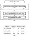
- a process for estimating the position of a receiver 120 is provided in FIG. 2 .
- the positioning signals 113 are transmitted from the non-GNSS transmitters 110 at step 205.
- the signals 113 and/or a GNSS signal 153 are received at a receiver at step 285, and an estimated position of the receiver (e.g. latitude, longitude and/or altitude) is generated using the signals 113 and/or the GNSS signal 153 at step 295.
- the signals 113 transmitted from the transmitters 110 at step 205 are generated using a PN code and a chipping rate selected to allow a receiver 120 to clearly resolve the multipath effects of the positioning signal.
- the PN codes may be selected to have desirable autocorrelation and cross-correlation properties. Chip rates of such positioning signals may be selected such that the bandwidth of the positioning signals is scaled for multipath resolvability.
- the bandwidth (e.g. null-to-null bandwidth) of a signal transmitted by the spread spectrum system is tied to the chipping rate of the signal.
- the RF bandwidth is usually chosen between R and 2 R where the R is the chipping rate. Bandwidth efficiency is of lesser importance in a positioning system. Instead, resolvability of a particular signal is of greater concern. Resolvability achievable with a particular signal is a function of its RF bandwidth.
- a code length of 2047 with a low autocorrelation property may be used for multipath performance.
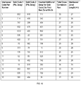
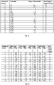
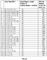
- FIG. 3 a table of example GNSS signal code durations, code lengths and chipping rates is depicted in FIG. 3 .
- An example non-GNSS positioning signal has a code length of 2047 and a chipping rate of 1.023 Mcps. This combination of code length and chipping rate is not included among the GNSS code lengths or durations shown in FIG. 3 . Consequently, at step 285 of FIG. 2 , a receiver 120 having only a GNSS positioning module may not be able to generate an estimated position of the receiver using such a non-GNSS positioning signal.
- a non-GNSS PN code and chipping rate combination e.g. a code of 1ms duration that occupies 5MHz of RF bandwidth
- existing GNSS receiver hardware can be used while retaining acceptable multipath performance.
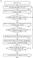
- a process for transmitting a non-GNSS positioning signal (e.g. one of the signals 113) from a non-GNSS transmitter (e.g. one of the transmitters 110), where the signal is compatible with a GNSS positioning module of a receiver 120, is provided in FIG. 4 .
- a bandwidth BW T is identified at step 415.
- the bandwidth BW T is selected to achieve multipath resolvability of transmitted positioning signals.
- a chipping rate of R Mcps having a bandwidth BW C , where 2 BW C ⁇ BW T and where R is equal to (or is a multiple of) a chipping rate used in a GNSS system is identified at step 425. In a different embodiment, 2 BW C > BW T .
- a PN code length is identified, where the PN code length 1) is equal to (or is a multiple of) a PN code length used in a GNSS system and/or 2) produces, at the chipping rate R , a PN code duration that is equal to (or a multiple of) a PN code duration used in a GNSS system.
- the above multiples for steps 425 and 435 can be the same integer or fraction.
- a PN code is generated that 1) has a length equal to the identified PN code length, 2) optionally is not a PN code used in GNSS systems (e.g.
- a transmit pulse shape having a bandwidth that exceeds the bandwidth BW C of the chipping rate R , and occupies (e.g. is equal to) the bandwidth BW T is generated at step 455. Details of generating the transmit pulse shape filter is discussed with reference to FIG. 7 .
- a positioning signal using the chipping rate R , the transmit pulse shape, and the PN code is generated at step 465, and the positioning signal is transmitted from the transmitter at step 475.
- the other criteria of step 445 includes criteria that the generated PN code has an autocorrelation peak to side lobe ratio greater than 50dB in a first region, and has an autocorrelation peak to side lobe ratio greater than 40dB in a second region, where the first region includes a region that is one or both of at least +/- 2500m from the main lobe or at least +/- 20 chips centered at zero lag, and where the second region is wider than the first region.
- the GNSS system that uses the chipping rate identified at step 425 is the same GNSS system as the GNSS system that uses the PN code length identified at step 435. In one another embodiment, the GNSS system that uses the chipping rate identified at step 425 is a different GNSS system than the GNSS system that uses the PN code length identified at step 435.
- the bandwidth BW T identified at step 415 conforms to a bandwidth of GNSS to allow for easier re-use of existing GNSS positioning modules.
- the bandwidth BW T is 5MHz.
- the chipping rate of R Mcps identified at step 425 is optionally selected from among existing GNSS chipping rates to achieve the bandwidth BW T .
- ICI inter-chip interference
- other PN code lengths, chipping rates and pulse shape combinations are possible.
- the positioning signal transmitted at step 475 can be used by a GNSS positioning module (e.g. GNSS hardware) of a receiver to generate an estimated position of the receiver (e.g. by estimating the range of travel for the signal, and using the range in a trilateration algorithm).
- a GNSS positioning module e.g. GNSS hardware
- a process for using a non-GNSS positioning signal e.g. one of the signals 113) and/or a GNSS signal (e.g. one of the signals 153) to estimate the position of a receiver (e.g. the receiver 120) is provided in FIG. 5 .
- first positioning information e.g. a pseudorange
- a positioning module e.g.
- second positioning information (e.g. a pseudorange) is generated by the positioning module using the GNSS signal at step 597.
- the position of the receiver is then estimated using the first positioning information and/or the second positioning information at step 598.
- the position of the receiver is estimated using high resolution signal processing methods to avoid mistaking side-lobes as multipath.
- High-resolution methods are a class of efficient multipath-resolution methods which use Eigen-space decompositions to locate the multipath components. Methods such as MUSIC, ESPIRIT fall under this class of resolution schemes that can better resolve closely-spaced multipath components than traditional methods for a given bandwidth.
- High resolution earliest time-of-arrival (TOA) methods attempt to estimate directly the TOA of an earliest path rather than inferring the peak position from the peak values.
- a partitioned matched filter with chip matched filter and code matched filter may be used by a receiver so GNSS acquisition and tracking hardware can be used for non-GNSS signals. The re-use of GNSS acquisition hardware on non-GNSS signals allows for the independent acquisition of each non-GNSS signal without additional/custom hardware.
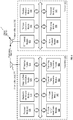
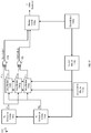
- FIG. 6 One embodiment of a system for generating signals from non-GNSS transmitters, and for processing the signals using a GNSS positioning module is depicted in FIG. 6 .
- a transmitter 110 includes various modules that are each operable to carry out different steps of FIG. 4 .
- a receiver 120 is also shown to include various modules that are each operable to carry out different steps of FIG. 5 .
- modules of the transmitter 110 may include: processor module(s) 605; a bandwidth identification module 615 operable to perform step 415; a chipping rate identification module 625 operable to perform step 425; a PN code length identification module 635 operable to perform step 435; a PN code generation module 645 operable to carry out step 445; a transmit pulse generation module 655 operable to perform step 455; a positioning signal generation module 665 operable to carry out step 465; and an RF interface module 675 and antenna module(s) 676 collectively operable to carry out step 475.
- the processor module(s) 605, the bandwidth identification module 615, the chipping rate identification module 625, the PN code length identification module 635, the PN code generation module 645 and the transmit pulse generation module 655 are coupled to the positioning signal generation module 665.
- the positioning signal generation module 665 is coupled to the RF interface module 675, and the RF interface module 675 is coupled to the antenna module(s) 676.
- modules of the receiver 120 may include: antenna module(s) 692; an RF frontend module 693; a digital frontend module 694; a PN code generation module 695; a positioning module 696 operable to perform step 596 and step 597; a position estimation module 698 operable to perform step 598; and processor modules(s) 699.
- the antenna module(s) 692 are coupled to the RF frontend module 693.
- the RF frontend module 693, the digital frontend module 694 and the PN code generation module 695 are coupled to the positioning module 696.
- the positioning module 696 is coupled to the position estimation module 698, and the position estimation module 698 is coupled to the processor modules(s) 699.
- the antenna module(s) 692 are coupled to the positioning module 696, and the positioning module 696 includes GNSS receiver hardware that is operable to determine an estimated position using GNSS positioning signals.
- a process for generating a transmit pulse shape filter that exceeds the bandwidth of a chipping rate and occupies a target transmission bandwidth (e.g. BW T ) is provided in FIG. 7 .
- a pulse shape filter is generated (e.g. a raised cosine function) at step 756.
- the generated pulse shape filter is scaled in the time domain such that the bandwidth of the scaled pulse shape filter occupies the bandwidth BW T at step 757.
- Step 756 and step 757 may occur as part of the same step.
- the pulse shape filter can be generated using a raised cosine filter scaled in time.
- the resulting pulse shape filter that exceeds the bandwidth of a chipping rate and occupies a bandwidth BW T is depicted in FIG. 8 .
- the filter response in dB is shown in IDB and IDB-A.
- IDB-A depicts an example where the chip rate ⁇ BW/2 (e.g. 2.046 Mcps chipping rate for 5.115MHz RF BW).
- a positioning signal of a lower chipping rate can achieve similar multipath resolvability as a positioning signal having a higher chipping rate.
- a positioning signal using a chipping rate of 2.046 Mcps can achieve the same resolvability as a positioning signal which uses a chipping rate of 2.5575 Mcps.
- PN code Various ways of generating a PN code are discussed below.
- One way to generate a PN code is to interleave two or more shorter PN codes (e.g. Gold codes) using delay modules or using initial PN generator fill values to generate a longer interleaved PN code.
- Another way to generate such a PN code is to truncate a maximal length code (m-sequence) to attain the desired PN code length.
- two or more PN codes are interleaved to generate an interleaved PN code that is suitable for a positioning system in terms of autocorrelation properties with a desired code duration (e.g. 1ms) for a particular chipping rate R .
- a desired code duration e.g. 1ms
- two or more 1023 length Gold codes that have a good zonal region adjacent to the autocorrelation peak are generated, in which the side lobe magnitudes are at most 1/1023 times the peak.
- the two or more generated PN codes are then interleaved to generate an interleaved PN code with a length that is a multiple of the base 1023 length and which also has good zonal region rejection.
- Two 1023 length PN codes when interleaved, will generate a length 2046 PN code.
- a length 2046 PN code at a chipping rate of 2.046 Mcps has the code length and the duration of Beidou L1 PN codes.
- the "good" zonal region (for autocorrelation/cross-correlation) is determined by the multipath environment.
- the spread of multipath will determine the zonal region to fit in the significant portion (enough amplitude) multipath profile so that we can detect the earliest arriving path for location. For example, a 1km multipath profile would require a 3us zonal region. That translates to different requirement of zonal region expressed in chips for different chipping rates.
- step 445 of FIG. 4 includes sub-steps provided in FIG. 9 .
- two or more sets of PN code generation parameters e.g. linear feedback shift register (LFSR) feedback taps, delay values, LFSR fill values, or other
- LFSR linear feedback shift register
- a first PN code (e.g. a length 1023 Gold code) is generated using a first set of PN code generation parameters at step 947.
- a determination is made at step 948 as to whether the first PN code satisfies first criteria (e.g. autocorrelation and/or cross-correlation criteria, good zonal regions of low autocorrelation, or other as discussed below). If it is determined that the first PN code satisfies the first criteria, flow continues to step 949.
- first criteria e.g. autocorrelation and/or cross-correlation criteria, good zonal regions of low autocorrelation, or other as discussed below.
- a second PN code (e.g. a second length 1023 Gold code) is generated using a second set of PN code generation parameters at step 949.
- a determination is made at step 950 as to whether the second PN code satisfies second criteria (e.g. autocorrelation and/or cross-correlation criteria, good zonal regions of low autocorrelation, or other as discussed below). If it is determined that the second PN code satisfies the second criteria, flow continues to step 951. However, if it is determined that the second PN code does not satisfy the second criteria, flow returns to step 946.
- second criteria e.g. autocorrelation and/or cross-correlation criteria, good zonal regions of low autocorrelation, or other as discussed below.
- Steps 947 through 950 are optionally repeated to generate a third and fourth PN code (e.g. a third Gold code and a fourth Gold code). Then, at step 952, the first PN code and second PN code (and optionally the third PN code and the fourth PN code) are interleaved to generate an interleaved PN code that has a code length equal to the PN code length identified at step 435 of FIG. 4 . A determination is made as to whether the interleaved PN code satisfies other criteria (e.g. autocorrelation and/or cross-correlation criteria) at step 953. If it is determined that the interleaved PN code does not satisfy the other criteria, flow returns to step 946.
- other criteria e.g. autocorrelation and/or cross-correlation criteria
- step 954 If it is determined that the interleaved PN code does satisfy the other criteria, flow continues to step 954.
- the interleaved PN code is used as the generated PN code at step 954.
- steps 948, 950 or 953 are optional.
- the first criteria of step 948 includes criteria that the first PN code (and optionally the third PN code) has an autocorrelation side lobe magnitude that is less than the autocorrelation peak magnitude of the first/third PN code divided by the length of the first/third PN code.
- the second criteria of step 950 includes criteria that the second PN code (and optionally the fourth PN code) has an autocorrelation side lobe magnitude that is less than the autocorrelation peak magnitude of the second/fourth PN code divided by the length of the second/fourth PN code.
- the other criteria of step 953 includes criteria that the interleaved PN code has an autocorrelation peak to side lobe ratio greater than 50dB in a first region, and has an autocorrelation peak to side lobe ratio greater than 40dB in a second region, where the first region includes a region that is one or both of 1) at least +/- 2500m from the main lobe or, 2) at least +/- 20 centered at zero lag, and where the second region is wider than the first region (e.g. at least +/- 50 chips centered at zero lag).
- the interleaved PN code has an autocorrelation peak to side lobe ratio greater than 50dB in a first region
- the interleaved PN code has an autocorrelation peak to side lobe ratio greater than 40dB in a second region
- the first region comprises a region that is one or both of 1) at least +/- 2500m from the main lobe, or 2) at least +/- 20 chips from the main lobe
- the second region is wider than the first region.
- the first PN code in a first region centered at zero lag, has an autocorrelation side-lobe magnitude that is less than a first threshold magnitude
- the second PN code in a second region centered at zero lag, has an autocorrelation side-lobe magnitude that is less than the first threshold magnitude
- the interleaved PN code in a third region centered at zero lag, has an autocorrelation side-lobe magnitude that is less than a second threshold magnitude
- the width of the third region is greater than a threshold width
- the width of the third region is less than the sum of the width of the first region summed with the width of the second region
- the first threshold magnitude is greater than 40 dB
- the second threshold magnitude is greater than 40 dB.
- the first threshold magnitude is less than 40 dB
- the second threshold magnitude is less than 40 dB.
- the second criteria of step 950 are the same as the first criteria of step 948.
- the first criteria and second criteria includes criteria that the first PN code and the second PN code have good zonal region rejection and additionally have good zonal region cross-correlation rejection relative to each other, for some relative phasing between the first PN code and the second PN code.
- the other criteria specified at step 953 includes determining if the interleaved PN code has a low auto-correlation in a first region and that the interleaved PN code has a medium auto-correlation in a second region, where the second region is wider than the first region. This is important for receivers which may need to use long impulse response filters (e.g. IIR) to notch out tone/other spurs.
- long impulse response filters e.g. IIR
- the zonal region centered at zero lag of the first PN code is of a first width
- the zonal region centered at zero lag of the second PN code is of a second width
- the zonal region centered at zero lag of the interleaved PN code is of a third width.
- the sum of the first width and the second width is greater than the third width, where the third width is greater than a threshold.
- two or more 1023 length Gold codes each with a desired zonal region adjacent to the autocorrelation peak, in which the side lobe magnitudes are at most 1/1023 time the peak, may be interleaved to generate an interleaved PN code with a length that is a multiple of the base 1023 length and which also has desired zonal region rejection.
- zonal region sizes There are at least two basic zonal region sizes that may be considered depending upon system requirements: (1) a zonal region size that is similar to that of PN codes to be interleaved, as measured in seconds, for the longer interleaved PN code; and (2) a zonal region size that is similar to that of the PN codes to be interleaved, as measured in chips, for the longer PN interleaved code.
- zonal region size consideration (1) if the zonal region was +/-10 chips adjacent to the autocorrelation peak for a positioning signal with a bandwidth of 1 MHz, then the zonal region would be +/-20 chips adjacent to the autocorrelation peak for a positioning signal having a bandwidth of 2MHz, +/-40 chips for a positioning signal having a bandwidth of 4 MHz, and so on.
- zonal region size consideration (2) the zonal regions are similar in chips for all positioning signal bandwidths.
- Zonal region size consideration (1) is more difficult to implement than zonal regions size consideration (2).
- Zonal region size consideration (1) also places a greater processing burden on the positioning module (e.g. high-resolution positioning algorithms such as MUSIC as well as other correlation hardware).
- the zonal region size consideration (1) also ensures that a multipath zonal region as specified in seconds is maintained. For example, a zonal region of 10 chips at a 1 MHz chip rate corresponds to multipath signals in a range of +/-3000 meters relative to a peak received signal. Reducing this range, as in requirement of zonal region size consideration (2) can result in missing direct path or low excess delay signals relative to the strongest received path.
- zonal region size consideration (1) may be more desirable than zonal region size consideration (2) in terms of system performance.
- each of the first PN code, the second PN code (and optionally third PN code and fourth PN code) are Gold codes.
- a first PN code (“Gold code 1") and a second PN code (“Gold code 2”) are interleaved to generate an interleaved PN code.
- Gold Code 1 is generated at step 947 of FIG. 9 .
- Gold Code 2 is generated at step 949 of FIG. 9 .
- Gold code 1 and Gold code 2 are selected together as a pair.
- the step of generating Gold code 1 may include sub-steps of identifying constituent PN codes used to generate the selected Gold code and then constructing the Gold code using the constituent PN codes.
- Gold code 1 and Gold code 2 may be generated using a first constituent PN code PN a and a second constituent PN code PN b .
- PN a is generated with a linear feedback shift register (LFSR) using feedback taps [3, 10]
- PN b is generated with an LFSR using feedback taps [2,3,6,8,9,10].
- Each Gold code is generated by combining PN a and PN b using an exclusive-OR operation, where PN b is delayed relative to PN a before the exclusive-OR operation is performed.
- the generated Gold codes are then interleaved to generate the interleaved PN code.
- One method of interleaving is where Gold code1 and Gold code 2 are interleaved such that the even numbered chips of the resultant interleaved PN code are of Gold code 1 and the odd numbered chips of the resultant interleaved PN code are of Gold code 2 (with the aforementioned delay).
- a relative delay between the first and second Gold codes is selected such that a low region of cross-correlation, such as -30dB, is achieved to be nearly center relative to the autocorrelations.
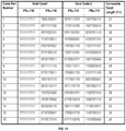
- FIG. 10 A table showing example sets of PN code generation delay parameters for generating two PN codes is illustrated in FIG. 10 .
- the first column of the table designates an interleaved code pair number.
- the interleaved code is generated by interleaving a pair of Gold codes (i.e. Gold code 1 and Gold code 2).
- Columns two and three of the table depict the delays of a constituent code PN b relative to a constituent code PN a , given that both PN a and PN b have the same initial fill.
- Column four of the table depicts an extra delay of Gold code 2 relative to Gold code 1. This extra delay ensures that the cross-correlation run is centered on the autocorrelation peak, except for a delay of -1 to compensate for the interlacing delay of 1.
- Gold code 1 is generated with constituent PN codes PN a and PN b , where the maximal of PN b has a relative delay of 853 samples relative to the maximal of PN a .
- Gold code 2 is generated with constituent PN codes PN a and PN b , where the maximal of PN b has a relative delay of 818 samples relative to the maximal of PN a .
- Gold code 1 and Gold code 2 generated using the parameters of row one, have autocorrelation functions with zonal regions of sizes +/-25 and +/-13 respectively (not shown).
- Column four of row one shows an additional delay of 711 samples applied to Gold code 2 relative to Gold code 1 before interleaving in order to generate a preferred zonal width. Note that the delay shown in column four of row one is actually 712 samples, however the inserted delay is 1 less than the center of the cross-correlation run to compensate for a delay of 1 sample in the interleaving procedure. As shown in column five of row one, the total cross-correlation run for the delay of 712 samples is shown to be 30. The resulting 2046 length interleaved PN code has a zonal length of 27, as shown in column six of row one.
- the length of the zonal region of the interleaved codes is at least 24.
- the autocorrelation zonal length of the composite interleaved codes is shown in the last column of the table. If the PN codes are restricted to the best 14 codes, the zonal region is at +/-25 chips or better. For some positioning systems this is a sufficient number of codes for the system, and is comparable to +/-12.5 chips at the 1 MHz rate.
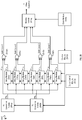
- FIG. 11 A system for interleaving two PN codes (e.g. Gold code 1 and Gold code 2) using delay modules is depicted in FIG. 11 .
- the modules may include: PN generation modules 1145a-b; a clock module 1145c; a counter module 1145d; a delay control module 1145e; delay modules 1145f-h; exclusive-OR modules 1145i-j; and a muxing module 1145k.
- the clock module 1145c is coupled to the counter module 1145d and to the muxing module 1145k.
- the counter module 1145d is coupled to the delay modules 1145f-h and is coupled to the PN generation modules 1145a-b.
- the delay control module 1145e is coupled to the delay modules 1145f-h.
- the PN generation modules 1145a-b are coupled to the delay modules 1145f-h.
- the PN generation module 1145a is coupled to the exclusive-OR module 1145i.
- the delay modules 1145f-h are coupled to the exclusive-OR modules 1145i-j, and the exclusive-OR modules 1145i-j are coupled to the muxing module 1145k.
- the delay control module 1145e is operable to use delay values as specified in the table shown in FIG. 10 to control the delay values of the delay modules 1145f-h.
- a first constituent PN code PN 1a is generated by the PN generation module 1145a with no delay.
- a second constituent PN code PN 1b is generated by the PN generation module 1145b.
- PN 1b is delayed by the delay module 1145f.
- PN 1a and PN 1b are combined by the exclusive-OR module 1145i to generate the first PN code ("Gold code 1").
- a third constituent PN code PN 2a is generated by the output PN generation module 1145a delayed by the delay module 1145g.
- a fourth constituent PN code PN 2b is generated by the output PN generation module 1145b delayed by the delay module 1145h.
- PN 2a and PN 2b are combined by the exclusive-OR module 1145j to generate the second PN code ("Gold code 2").
- Gold code 1 and Gold code 2 are interleaved by the muxing module 1145k to generate the interleaved PN code. As discussed with reference to column four of the table shown in FIG. 10 , an additional delay may be inserted to further offset Gold code 2 from Gold code 1 (e.g. the first chip of Gold code 2 is offset from the first chip of Gold code 1).
- the muxing module 1145k interleaves the two Gold codes (including the various delays) by taking a first chip from each of Gold code 1 and Gold code 2, then a second chip from each of Gold code 1 and Gold code 2, and so on. It is also possible to interleave two codes in other ways. In some embodiments, signs of each of the Gold codes used for interleaving may be altered.
- some embodiments interleave PN codes by loading initial PN generator fill values into constituent PN code generators to offset constituent PN codes from one another, which are then used to generate the two PN codes (e.g. two Gold codes).
- a table showing example sets of PN code generation fill parameters for generating two PN codes is illustrated in FIG. 12 .
- Four constituent PN codes (PN 1a , PN 1b , PN 2a , PN 2b ) are generated using initial fill values to offset the codes from one another.
- the fill values shown in columns two through five of the table incorporate the delays of column two through four of the table shown in FIG. 10 .
- the first 10 outputs of the PN code generator shift registers are the fill values read from left to right.
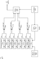
- FIG. 13 A system for interleaving a two PN codes using fill values is depicted in FIG. 13 .
- the modules may include: an initial fill command module 1345a; a clock module 1345b; a counter module 1345c; PN generation modules 1345d-g; exclusive-OR modules 1345h-i; and a muxing module 1345j.
- the clock module 1345b is coupled to the muxing module 1345j and to the counter module 1345c.
- the counter module 1345c is coupled to the PN generation modules 1345d-g.
- the initial fill command module 1345a is coupled to the PN generation modules 1345d-g.
- the PN generation modules 1345d-g are coupled to the exclusive-OR modules 1345h-i, and the exclusive-OR modules 1345h-i are coupled to the muxing module 1345j.
- the initial fill command module 1345a is operable to load initial fill values from columns two through five of the table shown in FIG. 12 into the PN generation modules 1345d-g.
- Constituent PN codes PN 1 a and PN 1b are combined by the exclusive-OR module 1345h to generate Gold code 1.
- Constituent PN codes PN 2a and PN 2b are combined by the exclusive-OR module 1345i to generate Gold code 2.
- Gold code 1 and Gold code 2 are then interleaved by the muxing module 1345j.
- the muxing module 1345j interleaves the two Gold codes (including the various delays) by taking a first chip from each of Gold code 1 and Gold code 2, then a second chip from each of Gold code 1 and Gold code 2, and so on. Note that it is also possible to interleave two codes in other ways. Also, the signs of the Gold codes may be altered, that is, the signs of each of the Gold codes used for interleaving may be altered.
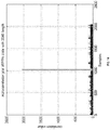
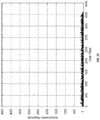
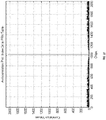
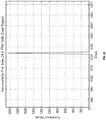
- FIG. 14 An autocorrelation plot of the 2046 length PN code generated by interleaving two 1023 length PN codes is depicted in FIG. 14 , and a magnified view of the autocorrelation plot of a PN code generated by interleaving two PN codes is depicted in FIG. 15 .
- the zonal region is considered to be the region surrounding the autocorrelation peak where the autocorrelation values of less than or equal to two.
- the one-sided zonal autocorrelation regions are 25 and 13 chips, and the one-sided cross correlation is 14 chips (total cross-correlation is 30, so 14 chips are one side of a desired location and 15 are on the other side).
- FIG. 14 shows the autocorrelation for the PN code with length 2046
- FIG. 15 shows a close up of the region around the autocorrelation peak.
- the zonal region is +/- 27 chips about the peak.
- the peak autocorrelation magnitude is two and hence its ratio relative to the overall peak of 2046 is 1023, just as in the 1023 length Gold code case.
- Gold codes may be interleaved to generate the interleaved PN code.
- four 1023 length PN codes are interleaved to generate a length 4092 PN code.
- a length 4092 PN code relates to the PN code length of Galileo E1B PN codes.
- steps 947 through 950 of FIG. 9 are optionally repeated to generate a third and a fourth PN code (Gold code 3 and Gold code 4).
- the four PN codes are then interleaved.
- identifying four PN codes that satisfy autocorrelation and cross-correlation criteria e.g.
- a code of length 1023 with cross-correlation zonal regions of magnitude 1/1023 may be more difficult than identifying two such PN codes.
- the criteria of the magnitude of the maximum side-lobes of the zonal region is relaxed in order to identify four suitable PN codes.
- This contrasts with Gold codes where, except for the zonal region of size 1/1023, the other regions have maximal of magnitude 65/1023 0.0635 (-23.9 dB).
- a PN code of length 4092 may result in a large zonal region with maximum side-lobes on the order of 65/4092 or around -36 dB, which should be acceptable for a high-resolution positioning algorithm. More precisely, the maximum side lobe relative to the peak for a number of codes found in this manner is determined to be 68/4092 (around -35.6 dB).
- FIG. 16 a table showing additional PN code generation delay parameters for generating two PN codes is illustrated in FIG. 16 and a table showing additional PN code generation fill parameters for generating two PN codes is illustrated in FIG. 17 .
- two PN code pairs are selected from the table of FIG. 10 and/or the table of FIG. 16 (or equivalently from the table of FIG. 12 and/or the table of FIG. 17 ).
- the second PN code pair is further delayed relative to the first PN code pair to optimize the zonal region, where maximum side lobe in the region is allowed to be less than 70/4092.
- the delay applied between the PN code pairs may be chosen to generate long zonal regions of maximum magnitude (e.g. 68/4092, or -35.6 dB).
- the four PN codes are then interleaved (including the various delays) where in succession four chips (or code values) are formed by taking a chip from each of the first PN code pair and then taking a chip from each of the second PN code pair.
- the resulting interleaved code is then of length 4092.
- the size of the zonal region of the interleaved PN code may vary from +/-51 chips to +/-83 chips, depending upon the PN code pair chosen.
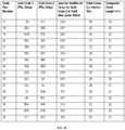
- FIG. 18 A table of example zonal regions resulting from interleaving four PN codes using delays is depicted in FIG. 18 .
- Column one of the table shown in FIG. 18 designates a particular interleaved code.
- Column two of the table indicates which code sets as designated in column one of FIG. 10 and/or FIG. 16 were interleaved to generate the resultant interleaved code.
- Column three of the table indicates the delay in samples of the second code set relative to the first code set.
- Column four of the table indicates the resultant zonal region of the interleaved code.
- each of the four generated PN codes is a Gold code.
- the four Gold codes are constructed from eight constituent PN codes, with the delays of the individual maximal length PN codes provided in the eight columns of the table shown.
- the output chip sequence of an interleaved PN code generated using Gold code 1 through Gold code 4 uses a chip from each of Gold code 1, Gold code 2, Gold code 3, Gold code 4 in that order, and then the constituent PN generators are shifted.
- PN 1a , PN 2a , PN 3a and PN 4a are generated using feedback taps [3,10] of a linear feedback shift register (LFSR), and PN 1b , PN 2b , PN 3b and PN 4b are generated using feedback taps [2,3,6,8,9,10] of an LFSR.
- the maximum side lobe magnitude in the resultant zonal region is 68/4092 (-35.6 dB) relative to the correlation peak.
- the modules may include: PN generation modules 2045a-b; a clock module 2045c; a counter module 2045d; a delay control module 2045e; delay modules 2045f-l; exclusive-OR modules 2045m-p; and a muxing module 2045q.
- the clock module 2045c is coupled to the counter module 2045d and is coupled to the muxing module 2045q.
- the counter module 2045d is coupled to the delay modules 2045f-l and is coupled to the PN generation modules 2045a-b.
- the delay control module 2045e is coupled to the delay modules 2045f-l.
- the PN generation modules 2045a-b are coupled to the delay modules 2045f-l.
- the PN generation module 2045a is coupled to the exclusive-OR module 2045m.
- the delay modules 2045f-l are coupled to the exclusive-OR modules 2045m-p, and the exclusive-OR modules 2045m-p are coupled to the muxing module 2045q.
- the delay control module 2045e is operable to use delay values as specified in the table shown in FIG. 19 to control the delay value of the delay modules 2045f-l.
- a first constituent PN code PN 1a is generated using the output of the PN generation module 2045a with no delay.
- a second constituent PN code PN 1b is generated using the output of the PN generation module 2045b delayed by the delay module 2045f.
- the constituent PN codes PN 1a and PN 1b are combined by the exclusive-OR module 2045m to generate Gold code 1.
- a third constituent PN code PN 2a is generated using the output of the PN generation module 2045a delayed by the delay module 2045g.
- a fourth constituent PN code PN 2b is generated using the output PN generation module 2045b delayed by the delay module 2045h.
- PN 2a and PN 2b are combined by the exclusive-OR module 2045n to generate Gold code 2.
- a fifth constituent PN code PN 3a is generated using the output of the PN generation module 2045a delayed by the delay module 2045i.
- a sixth constituent PN code PN 3b is generated using the output PN generation module 2045b delayed by the delay module 2045j.
- PN 3a and PN 3b are combined by the exclusive-OR module 2045o to generate Gold code 3.
- a seventh constituent PN code PN 4a is generated using the output of the PN generation module 2045a delayed by the delay module 2045k.
- An eighth constituent PN code PN 4b is generated using the output PN generation module 2045b delayed by the delay module 2045l.
- PN 4a and PN 4b are combined by the exclusive-OR module 2045p to generate Gold code 4.
- Gold code 1 through Gold code 4 are then interleaved by the muxing module 2045q to generate the interleaved PN code.
- the muxing module 2045q interleaves the four Gold codes (including the various delays) by taking a chip from each of Gold code 1 and Gold code 2, and then taking a chip from each of Gold code 3 and Gold code 4. Note that it is also possible to interleave the four codes in other ways, such as choosing chips from the first Gold code in each pair (e.g. Gold code 1 and Gold code 3), and then from the second Gold code in each pair (e.g. Gold code 2 and Gold code 4). The signs of each of the Gold codes used for interleaving may also be altered.
- FIG. 21 A table of example PN code generation fill parameters for generating four PN codes is depicted in FIG. 21 .
- the four PN codes are Gold codes.
- Gold code 1 through Gold code 4 are constructed from eight constituent PN codes (PN 1a , PN 1b , PN 2a , PN 2b , PN 3a , PN 3b , PN 4a and PN 4b ), with initial fill values of the individual maximal length PN codes provided in the eight columns of the table labeled PN 1a,b through PN 4a,b .
- the output chip sequence illustrated in the table of FIG. 21 is Gold Code 1, Gold Code 2, Gold Code 3, and Gold Code 4 in that order, and then the PN generators are shifted.
- PN 1a , PN 2a , PN 3a and PN 4a have feedback taps [3,10]
- PN 1b , PN 2b , PN 3b and PN 4b have feedback taps [2,3,6,8,9,10].
- the maximum side lobe magnitude in the zonal region is 68/4092 (-35.6 dB) relative to the correlation peak.
- the modules may include: an initial fill command module 2245a; a clock module 2245b; a counter module 2245c; PN generation modules 2245d-k; exclusive-OR modules 2245l-o; and a muxing module 2245p.
- the clock module 2245b is coupled to the muxing module 2245p and to the counter module 2245c.
- the counter module 2245c is coupled to the PN generation modules 2245d-k.
- the initial fill command module 2245a is coupled to the PN generation modules 2245d-k.
- the PN generation modules 2245d-k are coupled to the exclusive-OR modules 2245l-o, and the exclusive-OR modules 2245l-o are coupled to the muxing module 2245p.
- the initial fill command module 2245a is operable to load initial fill values from columns two through nine of the table shown in FIG. 21 into the PN generation modules 2245d-k. As shown, constituent PN codes PN 1a and PN 1b are combined by the exclusive-OR module 2245l to generate Gold code 1; constituent PN codes PN 2a and PN 2b are combined by the exclusive-OR module 2245m to generate Gold code 2; constituent PN codes PN 3a and PN 3b are combined by the exclusive-OR module 2245n to generate Gold code 3; and constituent PN codes PN 4a and PN 4b are combined by the exclusive-OR module 2245o to generate Gold code 4.
- Gold code 1 through Gold code 4 are then interleaved by the muxing module 2245p to generated an interleaved PN code.
- the muxing module 2245p interleaves the four Gold codes (including the various delays) by taking a chip from each of Gold code 1 and Gold code 2, and then taking a chip from each of Gold code 3 and Gold code 4. Note that it is also possible to interleave the four codes in other ways, such as choosing chips from the first Gold code in each pair (e.g. Gold code 1 and Gold code 3), and then from the second Gold code in each pair (e.g. Gold code 2 and Gold code 4). The signs of each of the Gold codes used for interleaving may also be altered.
- the embodiment shown in FIG. 22 which uses eight PN generators, requires less complexity to implement than the embodiment using delay modules shown in FIG. 20 .
- FIG. 23 An autocorrelation plot of a PN code generated by interleaving the first set of four PN codes shown in the table of FIG. 19 (if using delay modules to offset the constituent PN codes) or FIG. 21 (if using fill values to offset constituent PN codes) is depicted in FIG. 23 .
- FIG. 24 A magnified view of the autocorrelation plot of the PN code generated by interleaving the four PN codes is depicted in FIG. 24 .
- the maximum zonal side lobe level of 68/4092 is about 5.6 dB better than the peak side lobe level of Gold code of length 4095, the maximum of which is 129/4095 (-30 dB and, the length of the Gold code is not a multiple of 1023).
- Maximal length codes have a zonal region that is essentially the code length -1.
- One issue with maximal length codes is that the cross-correlation between different codes is not constrained, as in the case of Gold codes.
- the maximal cross-correlation is expected to be acceptable, especially if a selection is made among a subset of such codes.
- the performance with frequency offsets may not be significantly different than that associated with Gold codes having similar frequency offset.
- a length 2046 PN code (e.g. used for Beidou) can be constructed from a length 2047 m-sequence by truncating the m-sequence to 2046 samples. Performance in a large size zonal region is expected to be good because the effect of the truncation by T chips increases the autocorrelation magnitude (normally at 1 for nonzero offset) by at least T , since T samples are no longer available to enter into the autocorrelation summation. As the code phase shifts, however, additional bit mismatches occur corresponding to the overlap of the end of the sequence and the beginning of the sequence. In general, however, the autocorrelation values are less than this worst case amount since the effects of mismatches adds errors randomly.
- FIG. 25 One process for generating a PN code that has a code length related to an existing GNSS code length and satisfies other criteria is depicted in FIG. 25 .
- a set of m-sequence generation parameters e.g. LFSR feedback taps, or other
- an m-sequence having a code length that exceeds the PN code length identified at step 435 of FIG. 4 is generated using the set of m-sequence generation parameters.
- a determination is made as to whether the generated m-sequence satisfies first criteria (e.g. autocorrelation and/or cross-correlation criteria) at step 2548.
- first criteria e.g. autocorrelation and/or cross-correlation criteria
- step 2549 the selected m-sequence is truncated such that the truncated m-sequence 1) has a code length equal to the PN code length identified at step 435 of FIG. 4 , and 2 ) meets other criteria.
- a determination is made as to whether the truncated m-sequence satisfies the other criteria (e.g. autocorrelation and/or cross-correlation criteria) at step 2550.
- step 2546 If it is determined that the truncated m-sequence does not satisfy the other criteria, flow returns to step 2546. If it is determined that the truncated m-sequence satisfies the other criteria, flow continues to step 2551. The truncated m-sequence is used as the generated PN code at step 2551.
- the other criteria specified at step 2550 includes determining if the truncated m-sequence has a low auto-correlation in a first region and the truncated m-sequence has a medium auto-correlation in a second region.
- the other criteria of step 2550 includes criteria that the truncated m-sequence has an autocorrelation peak to side lobe ratio greater than 50dB in a first region, and has an autocorrelation peak to side lobe ratio greater than 40dB in a second region, where the first region includes a region that is at least +/- 20 chips centered at zero lag, and where the second region is wider than the first region.
- a table of truncated maximal length codes is shown at FIG. 26 .
- the first column of the table shows a code reference number.
- Each row of the second column is a listing of feedback taps used to generate the particular length 2047 m-sequence using an eleven stage (R11) linear feedback shift register (LFSR).
- Each row of the third column shows the zonal region length in chips adjacent to the autocorrelation peak of the length 2046 truncated code.
- Each row of the fourth column shows which PN chip is deleted from the length 2047 m-sequence in order to generate the truncated length 2046 code.
- the truncated m-sequence has an autocorrelation peak to side lobe ratio greater than 50dB in a first region
- the truncated m-sequence has an autocorrelation peak to side lobe ratio greater than 40dB in a second region
- the first region comprises a region that is one or both of 1) at least +/- 2500m from the main lobe, or 2) at least +/- 20 chips from the main lobe
- the second region is wider than the first region.
- the m-sequence, in a first region centered at zero lag has an autocorrelation side-lobe magnitude that is less than a first threshold magnitude
- the truncated m-sequence, in a second region centered at zero lag has an autocorrelation magnitude that is less than a second threshold magnitude
- the first threshold magnitude is greater than 40 dB
- the second threshold magnitude is greater than 40 dB.
- the first threshold magnitude is less than 40dB and the second threshold magnitude is less than 40dB.
- Truncated codes may be chosen with acceptable cross-correlation performance at zero frequency offset.
- the cross-correlation performance may be affected.
- some simulation indicates that the reduction afforded by choosing different initial fills is small, around 15%. Hence, the largest improvement would be afforded by choosing a better set of codes (e.g. a set of codes that meet the criteria).
- FIG. 27 An autocorrelation plot of a PN code generated by truncating a maximal-length PN code is depicted in FIG. 27 , and a magnified view of an autocorrelation plot of a PN code generated by truncating a maximal-length PN code is depicted in FIG. 28 .
- machine-readable media includes all forms of statutory machine-readable media (e.g. statutory non-volatile or volatile storage media, statutory removable or non-removable media, statutory integrated circuit media, statutory magnetic storage media, statutory optical storage media, or any other statutory storage media). As used herein, machine-readable media does not include non-statutory media.
- machines may include one or more computing device(s), processor(s), controller(s), integrated circuit(s), chip(s), system(s) on a chip, server(s), programmable logic device(s), other circuitry, and/or other suitable means described herein or otherwise known in the art.
- Method steps described herein may be order independent, and can therefore be performed in an order different from that described. It is also noted that different method steps described herein can be combined to form any number of methods, as would be understood by one of skill in the art. It is further noted that any two or more steps described herein may be performed at the same time. Any method step or feature disclosed herein may be expressly restricted from a claim for various reasons like achieving reduced manufacturing costs, lower power consumption, and increased processing efficiency. Method steps performed by a transmitter or a receiver can be performed by a server, or vice versa.
- Systems comprising one or more modules that perform, are operable to perform, or adapted to perform different method steps/stages disclosed herein are also contemplated, where the modules are implemented using one or more machines listed herein or other suitable hardware.
- the words comprise , comprising , include , including and the like are to be construed in an inclusive sense (i.e. not limited to) as opposed to an exclusive sense (i.e. consisting only of). Words using the singular or plural number also include the plural or singular number, respectively.
- the word or and the word and , as used in the Detailed Description cover any of the items and all of the items in a list.
- the words some , any and at least one refer to one or more.
- the term may is used herein to indicate an example, not a requirement-e.g. a thing that may perform an operation or may have a characteristic need not perform that operation or have that characteristic in each embodiment, but that thing performs that operation or has that characteristic in at least one embodiment.
- transmitters described herein may include: antenna module(s) for exchanging signals with other systems (e.g. satellites, other transmitters, receivers, a server); RF front end module(s) with circuitry components (e.g. analog/digital logic and power circuitry, tuning circuitry, buffer and power amplifiers, and other components as is known in the art or otherwise disclosed herein); processing module(s) for performing signal processing (e.g.
- sensors module(s) for measuring conditions at or near the transmitter (e.g. pressure, temperature, humidity, wind, or other conditions)
- interface module(s) for exchanging information with other systems via other links other than a radio link.
- Signals transmitted by a transmitter may carry different information that, once determined by a receiver or a server, may identify the following: the transmitter that transmitted the signal; the location (LLA) of that transmitter; pressure, temperature, humidity, and other conditions at or near that transmitter; and/or other information.
- a receiver may be in the form of a computing device (e.g. a mobile phone, tablet, laptop, digital camera, tracking tag).
- a receiver may also take the form of any component of the computing device, including a processor.
- a receiver may include: antenna module(s) for exchanging signals with other systems (e.g. satellites, terrestrial transmitters, receivers); RF front end module(s) with circuitry components (e.g. mixers, filters, amplifiers, digital-to-analog and analog-to-digital converters as is known in the art or otherwise disclosed herein); processing module(s) for signal processing of received signals to determine position information (e.g.
- memory module(s) for providing storage and retrieval of data and/or instructions relating to methods of operation described herein that may be executed by the processing module(s) or other module(s); sensor module(s) for measuring environmental conditions at or near the receiver (e.g. pressure, temperature, humidity, wind), which may be compared to the same environmental conditions at or near transmitters to determine the altitude of the receiver; other sensor module(s) for measuring other conditions (e.g.
- processing by the receiver can also occur at a server.
- positioning system may refer to satellite systems (e.g. Global Navigation Satellite Systems (GNSS) like GPS, GLONASS, Galileo, and Compass/Beidou), terrestrial systems, and hybrid satellite/terrestrial systems.
- GNSS Global Navigation Satellite Systems
- Positioning modules use various techniques to estimate the position of a receiver, including trilateration, which is the process of using geometry to estimate the position of a receiver using distances traveled by different "positioning" (or "ranging") signals that are received by the receiver from different beacons (e.g. terrestrial transmitters and/or satellites).
- trilateration is the process of using geometry to estimate the position of a receiver using distances traveled by different "positioning" (or "ranging") signals that are received by the receiver from different beacons (e.g. terrestrial transmitters and/or satellites).
- Positioning systems and methods that estimate a position of a receiver (in terms of latitude, longitude and/or altitude) based on positioning signals from beacons (e.g. transmitters, and/or satellites) and/or atmospheric measurements are described in co-assigned U.S. Patent No. 8,130,141, issued March 6, 2012 , and U.S. Patent Application Publication No. US 2012/0182180, published July 19, 2012 .
Landscapes
- Engineering & Computer Science (AREA)
- Radar, Positioning & Navigation (AREA)
- Remote Sensing (AREA)
- Computer Networks & Wireless Communication (AREA)
- Signal Processing (AREA)
- Physics & Mathematics (AREA)
- General Physics & Mathematics (AREA)
- Position Fixing By Use Of Radio Waves (AREA)
Claims (15)
- Verfahren zum Erzeugen und Übertragen eines Positionsbestimmungssignals von einem terrestrischen Sender (110) eines terrestrischen Positionsbestimmungssystems zur Verwendung durch eine GNSS-Empfänger-Hardware, wobei das Verfahren Folgendes umfasst:Identifizieren einer Chiprate, wobei die identifizierte Chiprate gleich einer oder ein Vielfaches einer GNSS-Chiprate ist;Identifizieren einer Pseudorandom-Noise(PN)-Codelänge, wobei die identifizierte PN-Codelänge gleich einer oder ein Vielfaches einer GNSS-PN-Codelänge ist;Erzeugen eines PN-Codes, wobei der erzeugte PN-Code eine Länge aufweist, die gleich der identifizierten PN-Codelänge ist;Identifizieren einer Übertragungsbandbreite, die ein ganzzahliges Vielfaches einer Chipbandbreite der identifizierten Chiprate überschreitet;Erzeugen einer Sendeimpulsform, die eine Bandbreite aufweist, die gleich der Übertragungsbandbreite ist;Verwenden der identifizierten Chiprate, des erzeugten Sendeimpulses und des erzeugten PN-Codes, um ein Positionsbestimmungssignal am terrestrischen Sender (110) zu erzeugen; undÜbertragen des Positionsbestimmungssignals von dem terrestrischen Sender (110).
- Verfahren nach Anspruch 1, wobei das Erzeugen eines PN-Codes Folgendes umfasst:Erzeugen eines ersten PN-Codes, wobei der erste PN-Code, in einem ersten Bereich, der bei null Verschiebung zentriert ist, eine Autokorrelation-Nebenkeulengröße aufweist, die kleiner als eine erste Schwellenwertgröße ist;Erzeugen eines zweiten PN-Codes, wobei der zweite PN-Code, in einem zweiten Bereich, der bei null Verschiebung zentriert ist, eine Autokorrelation-Nebenkeulengröße aufweist, die kleiner als die erste Schwellenwertgröße ist,wobei einer oder beide aus dem ersten PN-Code oder dem zweiten PN-Code Gold-Codes sind; undVerschachteln des ersten PN-Codes und des zweiten PN-Codes, um den PN-Code durch (i) Versetzen des zweiten PN-Codes relativ zum ersten PN-Code unter Verwendung eines aus 1) einem Verzögerungsmodul oder 2) einem Anfangsfüllwert eines PN-Code-Generators, und (ii) Kombinieren des ersten PN-Codes und des versetzten zweiten PN-Codes zu erzeugen,wobei der PN-Code, in einem dritten Bereich, der bei null Verschiebung zentriert ist, eine Autokorrelation-Nebenkeulengröße aufweist, die kleiner als eine zweite Schwellenwertgröße ist,wobei die Breite des dritten Bereichs größer als eine Schwellenwertbreite ist, undwobei die Breite des dritten Bereichs kleiner als eine Summe (i) der Breite des ersten Bereichs und (ii) der Breite des zweiten Bereichs ist.
- Verfahren nach Anspruch 1, wobei die Chipbandbreite der identifizierten Chiprate kleiner als die Hälfte der Übertragungsbandbreite ist.
- Verfahren nach Anspruch 1, wobei die identifizierte Chiprate kleiner als eine Hälfte der Übertragungsbandbreite ist.
- Verfahren nach Anspruch 1, wobei die identifizierte PN-Codelänge mit der identifizierten Chiprate eine PN-Codedauer produziert, die gleich einer oder ein Vielfaches einer PN-Codedauer, die in einem GNSS-System verwendet wird, ist.
- Verfahren nach Anspruch 1, wobei das Erzeugen eines PN-Codes Folgendes umfasst:Erzeugen eines ersten PN-Codes;Erzeugen eines zweiten PN-Codes; undVerschachteln des ersten PN-Codes und des zweiten PN-Codes, um einen verschachtelten PN-Code zu erzeugen, wobei der verschachtelte PN-Code der erzeugte PN-Code ist,wobei einer oder beide aus dem ersten PN-Code oder dem zweiten PN-Code Gold-Codes sind.
- Verfahren nach Anspruch 6, wobei das Verschachteln des ersten PN-Codes und des zweiten PN-Codes Folgendes umfasst:Versetzen des zweiten PN-Codes relativ zum ersten PN-Code unter Verwendung eines aus 1) einem Verzögerungsmodul oder 2) einem Anfangsfüllwert eines PN-Code-Generators; undKombinieren des ersten PN-Codes und des versetzten zweiten PN-Codes.
- Verfahren nach Anspruch 6, wobei:der erste PN-Code, in einem ersten Bereich, der bei null Verschiebung zentriert ist, eine Autokorrelation-Nebenkeulengröße aufweist, die kleiner als eine erste Schwellenwertgröße ist;der zweite PN-Code, in einem zweiten Bereich, der bei null Verschiebung zentriert ist, eine Autokorrelation-Nebenkeulengröße aufweist, die kleiner als die erste Schwellenwertgröße ist,der verschachtelte PN-Code, in einem dritten Bereich, der bei null Verschiebung zentriert ist, eine Autokorrelation-Nebenkeulengröße aufweist, die kleiner als eine zweite Schwellenwertgröße ist,die Breite des dritten Bereichs größer als eine Schwellenwertbreite ist, undwobei die Breite des dritten Bereichs kleiner als eine Summe (i) der Breite des ersten Bereichs und (ii) der Breite des zweiten Bereichs ist.
- Verfahren nach Anspruch 6, wobei das Verfahren Folgendes umfasst:Erzeugen eines dritten PN-Codes unter Verwendung eines dritten Satzes von PN-Code-Erzeugungsparametern; undErzeugen eines vierten PN-Codes unter Verwendung eines vierten Satzes von PN-Code-Erzeugungsparametern,wobei der verschachtelte PN-Code durch Verschachteln des ersten PN-Codes, des zweiten PN-Codes, des dritten PN-Codes und des vierte PN-Codes erzeugt wird.
- Verfahren nach Anspruch 1, wobei das Erzeugen eines PN-Codes Folgendes umfasst:Erzeugen einer m-Sequenz, die eine Codelänge aufweist, die die identifizierte PN-Codelänge überschreitet;Verkürzen der ausgewählten m-Sequenz, so dass die verkürzte m-Sequenz eine Codelänge aufweist, die gleich der identifizierten PN-Codelänge ist; undVerwenden der verkürzten m-Sequenz als der erzeugte PN-Code.
- Verfahren nach Anspruch 10, wobei:die m-Sequenz, in einem ersten Bereich, der bei null Verschiebung zentriert ist, eine Autokorrelation-Nebenkeulengröße aufweist, die kleiner als eine erste Schwellenwertgröße ist, unddie verkürzte m-Sequenz, in einem zweiten Bereich, der bei null Verschiebung zentriert ist, eine Autokorrelation-Nebenkeulengröße aufweist, die kleiner als eine zweite Schwellenwertgröße ist.
- Verfahren nach Anspruch 1, wobei das Verfahren Folgendes umfasst:Empfangen des Positionsbestimmungssignals an einem Empfänger; Erzeugen, unter Verwendung einer GNSS-Empfänger-Hardware, einer ersten Positionsbestimmungsinformation unter Verwendung des Positionsbestimmungssignals,wobei die erste Positionsbestimmungsinformation eine Pseudoentfernung beinhaltet; undSchätzen der Position des Empfängers unter Verwendung der ersten Positionsbestimmungsinformation.
- Verfahren nach Anspruch 12, wobei das Verfahren Folgendes umfasst:Empfangen eines GNSS-Signals am Empfänger; undErzeugen, unter Verwendung der GNSS-Empfänger-Hardware, einer zweiten Positionsbestimmungsinformation unter Verwendung des GNSS-Signals,wobei die zweite Positionsbestimmungsinformation eine Pseudoentfernung beinhaltet, undwobei die Position des Empfängers unter Verwendung der zweiten Positionsbestimmungsinformation geschätzt wird.
- System (100), das einen terrestrischen Sender aufweist, der dafür ausgelegt ist, ein Positionsbestimmungssignal zu übertragen, das von einem GNSS-Empfänger verwendet wird, um eine Position des GNSS-Empfängers zu schätzen, wobei das System ein oder mehrere Module beinhaltet, die dafür ausgelegt sind, eines der Verfahren nach den Ansprüchen 1-13 durchzuführen.
- Nicht flüchtiges, maschinenlesbares Medium oder nicht flüchtige, maschinenlesbare Medien, die Programmanweisungen enthalten, die, wenn sie von einer oder mehreren Maschinen ausgeführt werden, bewirken, dass das System nach Anspruch 14 eines der Verfahren nach den Ansprüchen 1-13 durchführt.
Applications Claiming Priority (2)
| Application Number | Priority Date | Filing Date | Title |
|---|---|---|---|
| US201562237317P | 2015-10-05 | 2015-10-05 | |
| PCT/US2016/055134 WO2017062306A1 (en) | 2015-10-05 | 2016-10-03 | Systems and methods for generating signals from terrestrial transmitters, and for processing the signals using gnss receiver hardware |
Publications (2)
| Publication Number | Publication Date |
|---|---|
| EP3359979A1 EP3359979A1 (de) | 2018-08-15 |
| EP3359979B1 true EP3359979B1 (de) | 2020-12-09 |
Family
ID=57209846
Family Applications (1)
| Application Number | Title | Priority Date | Filing Date |
|---|---|---|---|
| EP16788280.2A Not-in-force EP3359979B1 (de) | 2015-10-05 | 2016-10-03 | Systeme und verfahren zur erzeugung von signalen von terrestrischen sendern und zur verarbeitung der signale mittels gnss-empfänger-hardware |
Country Status (5)
| Country | Link |
|---|---|
| US (1) | US10444369B2 (de) |
| EP (1) | EP3359979B1 (de) |
| KR (1) | KR102712273B1 (de) |
| CN (1) | CN108450026B (de) |
| WO (1) | WO2017062306A1 (de) |
Families Citing this family (4)
| Publication number | Priority date | Publication date | Assignee | Title |
|---|---|---|---|---|
| US10775510B2 (en) | 2016-06-06 | 2020-09-15 | Brian G. Agee | Blind despreading of civil GNSS signals for resilient PNT applications |
| US11125888B2 (en) | 2016-06-06 | 2021-09-21 | Brian G. Agee | Multi-subband methods for reduced complexity, wideband blind resilient detection and geo-observable estimation of global navigation satellite signals |
| EP4600686A3 (de) | 2020-02-03 | 2025-11-05 | Brian AGEE | Robuste verteilte positionierungsnetzwerke |
| CN120677743A (zh) * | 2023-02-17 | 2025-09-19 | 苹果公司 | IoT NTN的增强型GNSS操作 |
Family Cites Families (11)
| Publication number | Priority date | Publication date | Assignee | Title |
|---|---|---|---|---|
| US6959030B1 (en) * | 1999-11-12 | 2005-10-25 | Itt Manufacturinger Enterprises, Inc. | Method and apparatus for generating an interleaved code |
| US8035555B2 (en) * | 2004-12-17 | 2011-10-11 | Jon Olafur Winkel | Spreading codes for a satellite navigation system |
| US8571088B2 (en) * | 2007-11-12 | 2013-10-29 | Qualcomm Incorporated | Suppression of multipath effects for received SPS signals |
| CA2736768A1 (en) * | 2008-09-10 | 2010-03-18 | Commlabs, Inc. | Wide area positioning system |
| US9057606B2 (en) | 2009-09-10 | 2015-06-16 | Nextnav, Llc | Wide area positioning system |
| US9119165B2 (en) * | 2009-09-10 | 2015-08-25 | Nextnav, Llc | Coding in a wide area positioning system (WAPS) |
| US8306093B2 (en) * | 2008-12-01 | 2012-11-06 | Qualcomm Incorporated | Method and apparatus for multipath mitigation |
| US9291712B2 (en) * | 2009-09-10 | 2016-03-22 | Nextnav, Llc | Cell organization and transmission schemes in a wide area positioning system (WAPS) |
| KR20120035840A (ko) * | 2010-10-06 | 2012-04-16 | 한국전자통신연구원 | 의사 gps 신호를 이용한 단말의 실내 위치 추적 시스템 및 방법 |
| KR20120050680A (ko) * | 2010-11-11 | 2012-05-21 | 한국전자통신연구원 | 항법 위성 중계장치 및 항법 위성 신호 중계 방법 |
| WO2012068159A1 (en) * | 2010-11-16 | 2012-05-24 | Savi Technology, Inc. | Rfid applications |
-
2016
- 2016-10-03 EP EP16788280.2A patent/EP3359979B1/de not_active Not-in-force
- 2016-10-03 KR KR1020187010799A patent/KR102712273B1/ko active Active
- 2016-10-03 WO PCT/US2016/055134 patent/WO2017062306A1/en not_active Ceased
- 2016-10-03 CN CN201680057848.5A patent/CN108450026B/zh active Active
- 2016-10-03 US US15/283,819 patent/US10444369B2/en active Active
Non-Patent Citations (1)
| Title |
|---|
| None * |
Also Published As
| Publication number | Publication date |
|---|---|
| WO2017062306A1 (en) | 2017-04-13 |
| EP3359979A1 (de) | 2018-08-15 |
| US20170097421A1 (en) | 2017-04-06 |
| KR102712273B1 (ko) | 2024-09-30 |
| KR20180063141A (ko) | 2018-06-11 |
| US10444369B2 (en) | 2019-10-15 |
| CN108450026A (zh) | 2018-08-24 |
| CN108450026B (zh) | 2022-05-03 |
Similar Documents
| Publication | Publication Date | Title |
|---|---|---|
| US9973234B2 (en) | Systems and methods for pseudo-random coding | |
| US8199047B2 (en) | High-precision radio frequency ranging system | |
| US9170319B2 (en) | Determining position of underwater node | |
| Sand et al. | Positioning in wireless communications systems | |
| Goswami | Indoor location technologies | |
| McEllroy | Navigation using signals of opportunity in the AM transmission band | |
| KR101467312B1 (ko) | 국소 신호에 기초한 boc 상관함수 생성 방법, boc 신호 추적 장치 및 이를 이용한 대역 확산 신호 수신 장치 | |
| EP2565672A2 (de) | Einordnung für drahtlose Funkkommunikationsvorrichtungen | |
| EP3359979B1 (de) | Systeme und verfahren zur erzeugung von signalen von terrestrischen sendern und zur verarbeitung der signale mittels gnss-empfänger-hardware | |
| EP2845326A1 (de) | Terrestrisches positions- und zeitsystem | |
| US20150063426A1 (en) | Systems and methods for pseudo-random coding | |
| Hegarty et al. | Binary coded symbol modulations for GNSS | |
| US10175945B2 (en) | Methods and systems for improving correlation | |
| Bastide et al. | GPS L5 and Galileo E5a/E5b signal-to-noise density ratio degradation due to DME/TACAN signals: Simulations and theoretical derivation | |
| US8570150B1 (en) | Sensing system and method with integral sensor locating capability | |
| US9784815B2 (en) | Separating ranging and data signals in a wireless positioning system | |
| EP2642312B1 (de) | Hardwarereduziertes System zur TDOA-Lokalisierung von Funkfrequenzemittern | |
| CN107064969A (zh) | 一种gnss接收机码相位估计与补偿方法 | |
| US7701998B2 (en) | Radio signal positioning | |
| Shin et al. | Development of end-to-end numerical simulator for next generation gnss signal design | |
| CN109425871B (zh) | 基于低轨卫星星座和c波段联合导航信号的卫星导航系统和方法 | |
| Abduljawad et al. | Custom GNSS signal simulator for LEO GNSS augmentation System | |
| Meiyappan et al. | Position, Navigation and Timing with Dedicated Metropolitan Beacon Systems | |
| Sark | Radio frequency ranging for precise indoor localization | |
| KR20260025871A (ko) | 영점 변조를 이용한 다중화 시스템 및 방법 |
Legal Events
| Date | Code | Title | Description |
|---|---|---|---|
| STAA | Information on the status of an ep patent application or granted ep patent |
Free format text: STATUS: UNKNOWN |
|
| STAA | Information on the status of an ep patent application or granted ep patent |
Free format text: STATUS: THE INTERNATIONAL PUBLICATION HAS BEEN MADE |
|
| PUAI | Public reference made under article 153(3) epc to a published international application that has entered the european phase |
Free format text: ORIGINAL CODE: 0009012 |
|
| STAA | Information on the status of an ep patent application or granted ep patent |
Free format text: STATUS: REQUEST FOR EXAMINATION WAS MADE |
|
| 17P | Request for examination filed |
Effective date: 20180329 |
|
| AK | Designated contracting states |
Kind code of ref document: A1 Designated state(s): AL AT BE BG CH CY CZ DE DK EE ES FI FR GB GR HR HU IE IS IT LI LT LU LV MC MK MT NL NO PL PT RO RS SE SI SK SM TR |
|
| AX | Request for extension of the european patent |
Extension state: BA ME |
|
| DAV | Request for validation of the european patent (deleted) | ||
| DAX | Request for extension of the european patent (deleted) | ||
| GRAP | Despatch of communication of intention to grant a patent |
Free format text: ORIGINAL CODE: EPIDOSNIGR1 |
|
| STAA | Information on the status of an ep patent application or granted ep patent |
Free format text: STATUS: GRANT OF PATENT IS INTENDED |
|
| INTG | Intention to grant announced |
Effective date: 20200716 |
|
| GRAS | Grant fee paid |
Free format text: ORIGINAL CODE: EPIDOSNIGR3 |
|
| GRAA | (expected) grant |
Free format text: ORIGINAL CODE: 0009210 |
|
| STAA | Information on the status of an ep patent application or granted ep patent |
Free format text: STATUS: THE PATENT HAS BEEN GRANTED |
|
| AK | Designated contracting states |
Kind code of ref document: B1 Designated state(s): AL AT BE BG CH CY CZ DE DK EE ES FI FR GB GR HR HU IE IS IT LI LT LU LV MC MK MT NL NO PL PT RO RS SE SI SK SM TR |
|
| REG | Reference to a national code |
Ref country code: GB Ref legal event code: FG4D |
|
| REG | Reference to a national code |
Ref country code: AT Ref legal event code: REF Ref document number: 1343997 Country of ref document: AT Kind code of ref document: T Effective date: 20201215 Ref country code: CH Ref legal event code: EP |
|
| REG | Reference to a national code |
Ref country code: DE Ref legal event code: R096 Ref document number: 602016049497 Country of ref document: DE |
|
| REG | Reference to a national code |
Ref country code: IE Ref legal event code: FG4D |
|
| PG25 | Lapsed in a contracting state [announced via postgrant information from national office to epo] |
Ref country code: FI Free format text: LAPSE BECAUSE OF FAILURE TO SUBMIT A TRANSLATION OF THE DESCRIPTION OR TO PAY THE FEE WITHIN THE PRESCRIBED TIME-LIMIT Effective date: 20201209 Ref country code: GR Free format text: LAPSE BECAUSE OF FAILURE TO SUBMIT A TRANSLATION OF THE DESCRIPTION OR TO PAY THE FEE WITHIN THE PRESCRIBED TIME-LIMIT Effective date: 20210310 Ref country code: NO Free format text: LAPSE BECAUSE OF FAILURE TO SUBMIT A TRANSLATION OF THE DESCRIPTION OR TO PAY THE FEE WITHIN THE PRESCRIBED TIME-LIMIT Effective date: 20210309 Ref country code: RS Free format text: LAPSE BECAUSE OF FAILURE TO SUBMIT A TRANSLATION OF THE DESCRIPTION OR TO PAY THE FEE WITHIN THE PRESCRIBED TIME-LIMIT Effective date: 20201209 |
|
| REG | Reference to a national code |
Ref country code: AT Ref legal event code: MK05 Ref document number: 1343997 Country of ref document: AT Kind code of ref document: T Effective date: 20201209 |
|
| PG25 | Lapsed in a contracting state [announced via postgrant information from national office to epo] |
Ref country code: SE Free format text: LAPSE BECAUSE OF FAILURE TO SUBMIT A TRANSLATION OF THE DESCRIPTION OR TO PAY THE FEE WITHIN THE PRESCRIBED TIME-LIMIT Effective date: 20201209 Ref country code: LV Free format text: LAPSE BECAUSE OF FAILURE TO SUBMIT A TRANSLATION OF THE DESCRIPTION OR TO PAY THE FEE WITHIN THE PRESCRIBED TIME-LIMIT Effective date: 20201209 Ref country code: BG Free format text: LAPSE BECAUSE OF FAILURE TO SUBMIT A TRANSLATION OF THE DESCRIPTION OR TO PAY THE FEE WITHIN THE PRESCRIBED TIME-LIMIT Effective date: 20210309 |
|
| REG | Reference to a national code |
Ref country code: NL Ref legal event code: MP Effective date: 20201209 |
|
| PG25 | Lapsed in a contracting state [announced via postgrant information from national office to epo] |
Ref country code: NL Free format text: LAPSE BECAUSE OF FAILURE TO SUBMIT A TRANSLATION OF THE DESCRIPTION OR TO PAY THE FEE WITHIN THE PRESCRIBED TIME-LIMIT Effective date: 20201209 Ref country code: HR Free format text: LAPSE BECAUSE OF FAILURE TO SUBMIT A TRANSLATION OF THE DESCRIPTION OR TO PAY THE FEE WITHIN THE PRESCRIBED TIME-LIMIT Effective date: 20201209 |
|
| REG | Reference to a national code |
Ref country code: LT Ref legal event code: MG9D |
|
| PG25 | Lapsed in a contracting state [announced via postgrant information from national office to epo] |
Ref country code: CZ Free format text: LAPSE BECAUSE OF FAILURE TO SUBMIT A TRANSLATION OF THE DESCRIPTION OR TO PAY THE FEE WITHIN THE PRESCRIBED TIME-LIMIT Effective date: 20201209 Ref country code: EE Free format text: LAPSE BECAUSE OF FAILURE TO SUBMIT A TRANSLATION OF THE DESCRIPTION OR TO PAY THE FEE WITHIN THE PRESCRIBED TIME-LIMIT Effective date: 20201209 Ref country code: LT Free format text: LAPSE BECAUSE OF FAILURE TO SUBMIT A TRANSLATION OF THE DESCRIPTION OR TO PAY THE FEE WITHIN THE PRESCRIBED TIME-LIMIT Effective date: 20201209 Ref country code: SM Free format text: LAPSE BECAUSE OF FAILURE TO SUBMIT A TRANSLATION OF THE DESCRIPTION OR TO PAY THE FEE WITHIN THE PRESCRIBED TIME-LIMIT Effective date: 20201209 Ref country code: SK Free format text: LAPSE BECAUSE OF FAILURE TO SUBMIT A TRANSLATION OF THE DESCRIPTION OR TO PAY THE FEE WITHIN THE PRESCRIBED TIME-LIMIT Effective date: 20201209 Ref country code: PT Free format text: LAPSE BECAUSE OF FAILURE TO SUBMIT A TRANSLATION OF THE DESCRIPTION OR TO PAY THE FEE WITHIN THE PRESCRIBED TIME-LIMIT Effective date: 20210409 Ref country code: RO Free format text: LAPSE BECAUSE OF FAILURE TO SUBMIT A TRANSLATION OF THE DESCRIPTION OR TO PAY THE FEE WITHIN THE PRESCRIBED TIME-LIMIT Effective date: 20201209 |
|
| PG25 | Lapsed in a contracting state [announced via postgrant information from national office to epo] |
Ref country code: PL Free format text: LAPSE BECAUSE OF FAILURE TO SUBMIT A TRANSLATION OF THE DESCRIPTION OR TO PAY THE FEE WITHIN THE PRESCRIBED TIME-LIMIT Effective date: 20201209 Ref country code: AT Free format text: LAPSE BECAUSE OF FAILURE TO SUBMIT A TRANSLATION OF THE DESCRIPTION OR TO PAY THE FEE WITHIN THE PRESCRIBED TIME-LIMIT Effective date: 20201209 |
|
| REG | Reference to a national code |
Ref country code: DE Ref legal event code: R097 Ref document number: 602016049497 Country of ref document: DE |
|
| PG25 | Lapsed in a contracting state [announced via postgrant information from national office to epo] |
Ref country code: IS Free format text: LAPSE BECAUSE OF FAILURE TO SUBMIT A TRANSLATION OF THE DESCRIPTION OR TO PAY THE FEE WITHIN THE PRESCRIBED TIME-LIMIT Effective date: 20210409 |
|
| PLBE | No opposition filed within time limit |
Free format text: ORIGINAL CODE: 0009261 |
|
| STAA | Information on the status of an ep patent application or granted ep patent |
Free format text: STATUS: NO OPPOSITION FILED WITHIN TIME LIMIT |
|
| PG25 | Lapsed in a contracting state [announced via postgrant information from national office to epo] |
Ref country code: AL Free format text: LAPSE BECAUSE OF FAILURE TO SUBMIT A TRANSLATION OF THE DESCRIPTION OR TO PAY THE FEE WITHIN THE PRESCRIBED TIME-LIMIT Effective date: 20201209 Ref country code: IT Free format text: LAPSE BECAUSE OF FAILURE TO SUBMIT A TRANSLATION OF THE DESCRIPTION OR TO PAY THE FEE WITHIN THE PRESCRIBED TIME-LIMIT Effective date: 20201209 |
|
| 26N | No opposition filed |
Effective date: 20210910 |
|
| PG25 | Lapsed in a contracting state [announced via postgrant information from national office to epo] |
Ref country code: DK Free format text: LAPSE BECAUSE OF FAILURE TO SUBMIT A TRANSLATION OF THE DESCRIPTION OR TO PAY THE FEE WITHIN THE PRESCRIBED TIME-LIMIT Effective date: 20201209 Ref country code: SI Free format text: LAPSE BECAUSE OF FAILURE TO SUBMIT A TRANSLATION OF THE DESCRIPTION OR TO PAY THE FEE WITHIN THE PRESCRIBED TIME-LIMIT Effective date: 20201209 |
|
| PG25 | Lapsed in a contracting state [announced via postgrant information from national office to epo] |
Ref country code: ES Free format text: LAPSE BECAUSE OF FAILURE TO SUBMIT A TRANSLATION OF THE DESCRIPTION OR TO PAY THE FEE WITHIN THE PRESCRIBED TIME-LIMIT Effective date: 20201209 |
|
| REG | Reference to a national code |
Ref country code: CH Ref legal event code: PL |
|
| PG25 | Lapsed in a contracting state [announced via postgrant information from national office to epo] |
Ref country code: IS Free format text: LAPSE BECAUSE OF FAILURE TO SUBMIT A TRANSLATION OF THE DESCRIPTION OR TO PAY THE FEE WITHIN THE PRESCRIBED TIME-LIMIT Effective date: 20210409 |
|
| REG | Reference to a national code |
Ref country code: BE Ref legal event code: MM Effective date: 20211031 |
|
| PG25 | Lapsed in a contracting state [announced via postgrant information from national office to epo] |
Ref country code: MC Free format text: LAPSE BECAUSE OF FAILURE TO SUBMIT A TRANSLATION OF THE DESCRIPTION OR TO PAY THE FEE WITHIN THE PRESCRIBED TIME-LIMIT Effective date: 20201209 |
|
| PG25 | Lapsed in a contracting state [announced via postgrant information from national office to epo] |
Ref country code: LU Free format text: LAPSE BECAUSE OF NON-PAYMENT OF DUE FEES Effective date: 20211003 Ref country code: BE Free format text: LAPSE BECAUSE OF NON-PAYMENT OF DUE FEES Effective date: 20211031 |
|
| PG25 | Lapsed in a contracting state [announced via postgrant information from national office to epo] |
Ref country code: LI Free format text: LAPSE BECAUSE OF NON-PAYMENT OF DUE FEES Effective date: 20211031 Ref country code: CH Free format text: LAPSE BECAUSE OF NON-PAYMENT OF DUE FEES Effective date: 20211031 |
|
| PG25 | Lapsed in a contracting state [announced via postgrant information from national office to epo] |
Ref country code: FR Free format text: LAPSE BECAUSE OF NON-PAYMENT OF DUE FEES Effective date: 20211031 |
|
| PG25 | Lapsed in a contracting state [announced via postgrant information from national office to epo] |
Ref country code: IE Free format text: LAPSE BECAUSE OF NON-PAYMENT OF DUE FEES Effective date: 20211003 |
|
| PG25 | Lapsed in a contracting state [announced via postgrant information from national office to epo] |
Ref country code: HU Free format text: LAPSE BECAUSE OF FAILURE TO SUBMIT A TRANSLATION OF THE DESCRIPTION OR TO PAY THE FEE WITHIN THE PRESCRIBED TIME-LIMIT; INVALID AB INITIO Effective date: 20161003 |
|
| PG25 | Lapsed in a contracting state [announced via postgrant information from national office to epo] |
Ref country code: CY Free format text: LAPSE BECAUSE OF FAILURE TO SUBMIT A TRANSLATION OF THE DESCRIPTION OR TO PAY THE FEE WITHIN THE PRESCRIBED TIME-LIMIT Effective date: 20201209 |
|
| PGFP | Annual fee paid to national office [announced via postgrant information from national office to epo] |
Ref country code: GB Payment date: 20230810 Year of fee payment: 8 |
|
| PGFP | Annual fee paid to national office [announced via postgrant information from national office to epo] |
Ref country code: DE Payment date: 20231018 Year of fee payment: 8 |
|
| PG25 | Lapsed in a contracting state [announced via postgrant information from national office to epo] |
Ref country code: MK Free format text: LAPSE BECAUSE OF FAILURE TO SUBMIT A TRANSLATION OF THE DESCRIPTION OR TO PAY THE FEE WITHIN THE PRESCRIBED TIME-LIMIT Effective date: 20201209 |
|
| PG25 | Lapsed in a contracting state [announced via postgrant information from national office to epo] |
Ref country code: MT Free format text: LAPSE BECAUSE OF FAILURE TO SUBMIT A TRANSLATION OF THE DESCRIPTION OR TO PAY THE FEE WITHIN THE PRESCRIBED TIME-LIMIT Effective date: 20201209 |
|
| REG | Reference to a national code |
Ref country code: DE Ref legal event code: R119 Ref document number: 602016049497 Country of ref document: DE |
|
| GBPC | Gb: european patent ceased through non-payment of renewal fee |
Effective date: 20241003 |
|
| PG25 | Lapsed in a contracting state [announced via postgrant information from national office to epo] |
Ref country code: DE Free format text: LAPSE BECAUSE OF NON-PAYMENT OF DUE FEES Effective date: 20250501 |
|
| PG25 | Lapsed in a contracting state [announced via postgrant information from national office to epo] |
Ref country code: GB Free format text: LAPSE BECAUSE OF NON-PAYMENT OF DUE FEES Effective date: 20241003 |
|
| PG25 | Lapsed in a contracting state [announced via postgrant information from national office to epo] |
Ref country code: TR Free format text: LAPSE BECAUSE OF FAILURE TO SUBMIT A TRANSLATION OF THE DESCRIPTION OR TO PAY THE FEE WITHIN THE PRESCRIBED TIME-LIMIT Effective date: 20201209 |