EP3359912B1 - Method and system for tyre condition analysis - Google Patents
Method and system for tyre condition analysis Download PDFInfo
- Publication number
- EP3359912B1 EP3359912B1 EP16781192.6A EP16781192A EP3359912B1 EP 3359912 B1 EP3359912 B1 EP 3359912B1 EP 16781192 A EP16781192 A EP 16781192A EP 3359912 B1 EP3359912 B1 EP 3359912B1
- Authority
- EP
- European Patent Office
- Prior art keywords
- tyre
- flash
- light
- images
- flashes
- Prior art date
- Legal status (The legal status is an assumption and is not a legal conclusion. Google has not performed a legal analysis and makes no representation as to the accuracy of the status listed.)
- Active
Links
- 238000000034 method Methods 0.000 title claims description 17
- 238000004458 analytical method Methods 0.000 title claims 2
- 238000003384 imaging method Methods 0.000 claims description 47
- 238000012545 processing Methods 0.000 claims description 12
- 230000001154 acute effect Effects 0.000 claims description 7
- 238000004519 manufacturing process Methods 0.000 claims description 3
- 230000001360 synchronised effect Effects 0.000 claims description 3
- 230000004913 activation Effects 0.000 description 12
- 238000005286 illumination Methods 0.000 description 7
- 238000007689 inspection Methods 0.000 description 4
- 230000002045 lasting effect Effects 0.000 description 4
- 230000009849 deactivation Effects 0.000 description 3
- 239000011324 bead Substances 0.000 description 2
- 238000005336 cracking Methods 0.000 description 2
- 238000010586 diagram Methods 0.000 description 2
- 238000010191 image analysis Methods 0.000 description 2
- 230000003213 activating effect Effects 0.000 description 1
- 230000008901 benefit Effects 0.000 description 1
- 238000004891 communication Methods 0.000 description 1
- 230000007423 decrease Effects 0.000 description 1
- 230000000694 effects Effects 0.000 description 1
- 238000000605 extraction Methods 0.000 description 1
- 238000005259 measurement Methods 0.000 description 1
- 238000012015 optical character recognition Methods 0.000 description 1
- 230000008569 process Effects 0.000 description 1
- 230000008439 repair process Effects 0.000 description 1
- 238000005096 rolling process Methods 0.000 description 1
- 238000012360 testing method Methods 0.000 description 1
- 239000005341 toughened glass Substances 0.000 description 1
- 230000001960 triggered effect Effects 0.000 description 1
- 229910052724 xenon Inorganic materials 0.000 description 1
- FHNFHKCVQCLJFQ-UHFFFAOYSA-N xenon atom Chemical compound [Xe] FHNFHKCVQCLJFQ-UHFFFAOYSA-N 0.000 description 1
Images


Classifications
-
- G—PHYSICS
- G01—MEASURING; TESTING
- G01M—TESTING STATIC OR DYNAMIC BALANCE OF MACHINES OR STRUCTURES; TESTING OF STRUCTURES OR APPARATUS, NOT OTHERWISE PROVIDED FOR
- G01M17/00—Testing of vehicles
- G01M17/007—Wheeled or endless-tracked vehicles
- G01M17/02—Tyres
- G01M17/027—Tyres using light, e.g. infrared, ultraviolet or holographic techniques
-
- B—PERFORMING OPERATIONS; TRANSPORTING
- B60—VEHICLES IN GENERAL
- B60C—VEHICLE TYRES; TYRE INFLATION; TYRE CHANGING; CONNECTING VALVES TO INFLATABLE ELASTIC BODIES IN GENERAL; DEVICES OR ARRANGEMENTS RELATED TO TYRES
- B60C11/00—Tyre tread bands; Tread patterns; Anti-skid inserts
- B60C11/24—Wear-indicating arrangements
- B60C11/246—Tread wear monitoring systems
-
- G—PHYSICS
- G01—MEASURING; TESTING
- G01B—MEASURING LENGTH, THICKNESS OR SIMILAR LINEAR DIMENSIONS; MEASURING ANGLES; MEASURING AREAS; MEASURING IRREGULARITIES OF SURFACES OR CONTOURS
- G01B11/00—Measuring arrangements characterised by the use of optical techniques
- G01B11/22—Measuring arrangements characterised by the use of optical techniques for measuring depth
-
- G—PHYSICS
- G01—MEASURING; TESTING
- G01B—MEASURING LENGTH, THICKNESS OR SIMILAR LINEAR DIMENSIONS; MEASURING ANGLES; MEASURING AREAS; MEASURING IRREGULARITIES OF SURFACES OR CONTOURS
- G01B11/00—Measuring arrangements characterised by the use of optical techniques
- G01B11/24—Measuring arrangements characterised by the use of optical techniques for measuring contours or curvatures
- G01B11/2433—Measuring arrangements characterised by the use of optical techniques for measuring contours or curvatures for measuring outlines by shadow casting
-
- G—PHYSICS
- G06—COMPUTING; CALCULATING OR COUNTING
- G06T—IMAGE DATA PROCESSING OR GENERATION, IN GENERAL
- G06T7/00—Image analysis
- G06T7/0002—Inspection of images, e.g. flaw detection
-
- G—PHYSICS
- G06—COMPUTING; CALCULATING OR COUNTING
- G06T—IMAGE DATA PROCESSING OR GENERATION, IN GENERAL
- G06T7/00—Image analysis
- G06T7/50—Depth or shape recovery
- G06T7/507—Depth or shape recovery from shading
-
- G—PHYSICS
- G06—COMPUTING; CALCULATING OR COUNTING
- G06T—IMAGE DATA PROCESSING OR GENERATION, IN GENERAL
- G06T2207/00—Indexing scheme for image analysis or image enhancement
- G06T2207/10—Image acquisition modality
- G06T2207/10141—Special mode during image acquisition
- G06T2207/10152—Varying illumination
-
- G—PHYSICS
- G06—COMPUTING; CALCULATING OR COUNTING
- G06T—IMAGE DATA PROCESSING OR GENERATION, IN GENERAL
- G06T2207/00—Indexing scheme for image analysis or image enhancement
- G06T2207/30—Subject of image; Context of image processing
- G06T2207/30248—Vehicle exterior or interior
- G06T2207/30252—Vehicle exterior; Vicinity of vehicle
-
- H—ELECTRICITY
- H04—ELECTRIC COMMUNICATION TECHNIQUE
- H04N—PICTORIAL COMMUNICATION, e.g. TELEVISION
- H04N7/00—Television systems
- H04N7/18—Closed-circuit television [CCTV] systems, i.e. systems in which the video signal is not broadcast
- H04N7/188—Capturing isolated or intermittent images triggered by the occurrence of a predetermined event, e.g. an object reaching a predetermined position
Definitions
- This invention relates to a method and apparatus for assessing the condition of a vehicle tyre on a wheel, whilst the wheel is rotating and the vehicle is moving.
- the invention is concerned with measuring the depth of tread on the tyre.
- US 2012/0020526 discloses a system and method related thereto, for automatically inspecting at least one tire of a moving vehicle.
- a system is disclosed in US 5987978 for measuring the tread depth of a tyre.
- a light source is used to illuminate a tyre obliquely, in such a way that shadows are formed within the recessed portions of the tread pattern.
- a second light source is provided for illuminating the tyre from a different direction.
- the first and second light sources may be arranged to operate in an alternating sequence and may be arranged such that the light they produce comes from opposing directions. Those portions of the tyre which are illuminated will reflect a greater intensity of light than those portions at the bottom of the treads which are in a shadowed region.
- the reflected light patterns when the tyre is illuminated from each side it is possible to work out the depth of the tread. It is stated that as the tyre wears, the depth of the tread grooves decreases and eventually they will wear down to such an extent that light can be reflected from the bottom of the grooves. It is stated that once this occurs, the width of the shadow is directly related to the depth of the tread.
- the reflected light is directed towards a camera, where the image is captured and sent to a data processor for processing.
- the apparatus of US 5987978 does not measure the tread depth of a tyre at multiple positions around its circumference, whilst the tyre is rotating and moving along a surface. Instead, the tyre may be rotated on a test bed such as a rolling road, or a sensor may be moved around the periphery of a tyre, for example during a roadside inspection.
- US 8542881 there is disclosed a computer vision aided automated tyre inspection system for in-motion inspection of vehicle tyres.
- a camera at an image acquisition station captures digital images of tyres of an approaching vehicle, and in particular the treads and sidewalls as the vehicle passes through an inspection station. There is a light at the image acquisition station, and this may also be physically separate from the image acquisition station. Sufficient images are captured to cover an entire revolution of a tyre. It is stated that the images are analysed to determine tyre tread depth. There is no disclosure of how the tread depth is measured, using the images.
- WO2015/059457 there is disclosed a system for measuring the depth of tread of a tyre on a wheel of a vehicle whilst the wheel is rotating and moving along the ground.
- a camera captures images whilst the tyre rotates for at least the major part of its circumference.
- Light sources are spaced longitudinally and are directed at an acute angle to the path of the tyre, to illuminate the tyre whilst images are captured.
- the images are analysed by data processing apparatus and the tread depth is determined from the length of shadows in the gaps between tread blocks.
- the light sources are activated and de-activated sequentially in accordance with signals from longitudinally spaced sensors which detect the presence of the tyre, so that when an image is captured of a portion of the tyre tread, only one light source is activated to illuminate that portion of the tyre tread.
- the speed of the vehicle is determined, and the sequence of activation and de-activation of the flash units sequentially is time-based.
- FIG. 1 is an illustration of a first embodiment of a system, in diagrammatic form.
- a truck 1 has ten wheels indicated at 2, and is travelling in a direction indicated by arrow A.
- two imaging devices Positioned below the level of the truck body are two imaging devices in the form of digital still cameras 3 and 4, respectively directed at an acute angle at wheels on the left hand side of the truck and the right hand side of the truck.
- a first series of flash units F1, F2, F3 and F4 are arranged longitudinally spaced along a line running generally parallel to the path of movement of the truck, outside the left hand side of the truck.
- a second series of flash units F5, F6, F7 and F8 are arranged longitudinally spaced along a line running generally parallel to the path of movement of the truck, outside the right hand side of the truck.
- Each flash unit consists of two xenon flash tubes, described in more detail below, and effectively operates as a single source of light.
- the wheel 2 is fitted with a pneumatic rubber tyre 5 and rotates in the direction of arrow B, whilst moving in a longitudinal direction over a base 6 as indicated by arrow A. Both cameras image a region 7 of the tyre beneath the bodywork of the truck 1.
- the right hand side of the vehicle is illustrated diagrammatically, with camera 4 shown; the other side corresponds.
- Figure 3 illustrates diagrammatically the left hand side, showing how the flash unit F4 is used to illuminate the region 7 of the tyre, whilst the camera 3 captures an image.
- a data processing unit 8 which also receives the image data from the cameras and can manipulate the data and calculate tread depths.
- Image data and other data can be displayed on a screen 9.
- Figure 4 shows a portion of the tyre 5, which has blocks of tread 10 separated by gaps 11.
- Figure 5 shows how shadows are formed when the surface of the tyre 5 is illuminated by a flash unit such as F1.
- a shadow portion 12 extending down the side of the tread gap 11, and a shadow portion 13 extending part way across the base. As the depth of the tread gap 11 becomes less, with wear of the tyre, both shadows shorten.
- the flash units are operated under the control of the data processing unit 8. It will be appreciated that the data processing unit could comprise a number of separate pieces of equipment linked together to perform the functions required by a method in accordance with the invention.
- Figure 6 shows an alternative arrangement similar to Figure 2 , in which the camera 4 is recessed below the surface 6.
- the camera may be covered by a window 14 of toughened glass or the like, so that it will not be damaged by the wheel and tyre passing overhead.
- Figure 7 illustrates a system for detecting the distance of an object O.
- An observation plane OP is arranged at an acute angle ⁇ to the path of movement B of a tyre.
- the distance D1 from the observation plane to a starting point, P1, where the taking of images is triggered, is known from a calibration step.
- the distance D2 can be calculated.
- a camera will be positioned on the observation plane and the true distance L will be related to the distance apparent on the image, such as a number of pixels.
- the direction the lens of the camera is facing will be at the angle ⁇ to the path of movement B.
- the object O could be anything suitable, such as the centre of the wheel as identified in the images.
- Figure 8 shows the arrangement of the camera 3 and the flash units F1 to F4 in more detail.
- the arrangement for the camera 4 and flash units F5 to F8 corresponds.
- the path of travel of a tyre being imaged is indicated at C.
- the field of view of the camera is indicated by segment 15 and is arranged so that over a considerable length of its path or travel, the tyre lies within this field of view.
- the flash units F1 to F2 are positioned at equal spacings along a line 16 which is parallel to line of travel C of the tyre, and displaced to the left of that line of travel.
- the flash units F1, F2, F3 and F4 illuminate segments marked respectively as 17, 18, 19 and 20. These segments of illumination overlap and are directed at acute angles to the path of travel of the tyre. Between them, the segments of illumination cover the entire path of travel of the tyre which falls within the field of view of the camera.
- sensors S1, S2, S3 and S4 which detect the presence of the wheel / tyre.
- the sensors are all in communication with the data processing 8.
- the flash units F1 to F4 are not activated.
- sensor S1 This communicates with the data processing unit and activates flash unit F1.
- sensor S2 which causes flash unit F2 to be activated.
- sensor S3 which causes flash unit F3 to be activated.
- sensor S4 which causes flash unit F4 to be activated.
- a flash unit Once a flash unit has been activated it produces a series of flashes of light for a predetermined period of time, at a predetermined flash rate, for example generating a burst over a period of about 0.1 second to about 1 second, at a flash rate of about 25 flashes per second, i.e. flashes fired at 40 ms intervals.
- the width of each flash pulse will be, for example, between 135 ⁇ s and 150 ⁇ s.
- the flash unit will then be deactivated to provide time to recharge. Typically this may take about a second and in some embodiments the flash unit will be activated for about a second and then deactivated for at least about a second before being activated again. In some cases a flash unit will not be activated again unless another tyre is detected by the associated sensor.
- the arrangement is such that the flash pulses produced by flash unit F2 are generated in the spaces between the individual pulses produced by flash units F1 and F3; and the flash pulses produced by flash unit F4 are generated in the spaces between the individual pulses produced by flash unit F3.
- two adjacent flash units do not produce individual pulses at the same time and a portion of a tyre is not illuminated by two flash units at the same moment in time. For this reason, it is not necessary to deactivate one flash unit when the tyre moves into an area of overlap between the coverage of two flash units, before the next flash unit in the series is activated.
- a fifth sensor S5 is provided which detect the presence of the wheel / tyre as it leaves the region where images are being captured.
- a speed sensor 21 which can be in the form of two closely spaced road mounted pressure switches. This can feed speed information to the data processing unit 8, to adjust the parameters of the system.
- This sensor may also provide information about the number of axles and the spacing between the axles.
- a further image capturing device 22 which captures data about the vehicle which can also be fed to the data processing unit 8 to identify the type of vehicle.
- this can be used to detect the speed. As the distances between all of the sensors S1 to S5 are known, a check can be kept on speed as a vehicle progresses.
- the data processing unit contains a module which produces signals which are fed to the flash units F1 to F8 and to the imaging devices 3 and 4. These signals control when the imaging device captures images; when the flash units are activated and de-activated; and the timing of the individual pulses when a flash unit is activated.
- the image capture device must be synchronised with the production of the individual flashes of light when flash units are activated.
- Figure 9 shows the sequence of activation and deactivation of the flash units F1 and F2, with respect to time.
- the flash unit F1 has periods 23 of activation, lasting for one second, alternating with periods 24 of de-activation lasting for one second.
- Flash unit F2 has periods 25 of activation, lasting for one second, alternating with periods 26 of de-activation lasting for one second.
- the activation periods 25 of flash unit F2 are displaced in time from the activation periods 23 of flash unit F1, as activation of F2 commences later than activation of F2.
- the activation periods of F1 and F2 are displaced, there is a zone marked 27 where both flash units are activated.
- FIG. 10 shows zone of overlap in more detail.
- the flash unit F1 When flash F1 is activated, for periods 23, the flash unit F1 emits a series of pulses of light P, which are separated by intervals G. There is then a period 24 of deactivation when no pulses are emitted.
- Flash unit F2 remains in a period 26 of deactivation after flash unit F1 has been activated, but whilst flash unit F1 is still in a period of activation 23, flash unit F2 enters a period of activation 25 and this results in a region of overlap 27 when both flash units F1 and F2 are in a state of activation.
- flash unit F2 When activated, flash unit F2 also emits a series of pulses of light P, which are separated by intervals G, and the profile of this series of pulses matches that of flash unit F1.
- the series of pulses emitted by flash unit F2 when activated is out of phase with the series of pulses emitted by flash unit F1 when activated, so that the pulses P emitted by flash unit F2 are emitted in the intervals G between pulses emitted by flash unit F1, and vice versa.
- the pulses of the two flash units do not coincide. In this manner, the tyre is not illuminated by two flash units at the same time.
- FIG 11 shows a layout of a system for use with a heavy goods vehicle (HGV).
- V represents a centre line V of a vehicle which is moving.
- Target areas for imaging are shown as A1, A2, A3 and A4.These are illuminated by four longitudinally spaced, rearward facing flash units 28, 29, 30 and 31 which are arranged along the centre line V, respectively illuminating primarily target areas A1, A2, A3 and A4.
- the target areas are also illuminated by four longitudinally spaced forward facing flash units 32, 33, 34 and 35, respectively illuminating primarily target areas A1, A2, A3 and A4.
- the flash units are operated in sequence as noted earlier, and the flashes are out of phase as necessary if they are activated at the same time.
- the rear facing flash units may be operated out of phase with the front facing flash units, so that each rear flash unit is initiated at a 1/50 th delay with respect to the front facing camera units.
- Images are captured by rear facing cameras 36 and 37, and front facing cameras 38 and 39.
- rear facing flash unit 40 and front facing flash unit 41 As well as rear facing camera 42 and front facing camera 43. They provide a close coupled system closer to the wheels of a vehicle, which can image difficult areas. Typically the amount of coverage is limited but at least some images can be captured.
- FIG 12 shows an HGV 44 which is driven through the system illustrated in Figure 11 .
- the arrangement is duplicated for the other side of the vehicle by a mirror image of the arrangement shown in Figure 11 .
- Tyre T5 is likely to be a difficult one to image as it is obstructed by tyres T4 and T6.
- the system provides coverage around the circumference for all tyres except T5, where the close coupled system provides 20° of coverage and the other cameras cannot image the tyre at all.
- FIG 13 shows a schematic top view representation of an embodiment of a side wall imaging system 45 in accordance with aspects of the present invention.
- the imaging system 45 comprises a first imaging section 46 and a second imaging section 47 for imaging a wheel on a vehicle 48 as it drives past.
- the first imaging section 46 comprises a first camera 49 and first and second flash units 50, 51.
- First camera 49 is positioned so that the top half 52 of the vehicle tyre 53 passes through the camera's field of view 54 as the vehicle 48 drives past.
- First and second flash units 50, 51 are positioned to illuminate the side wall 55 of the vehicle tyre 53.
- the first flash unit 50 is positioned to illuminate a near end 56 of the tyre 53, while flash unit 51 is positioned to illuminate a far side 57 of the tyre 53. Illumination across the tyre 53 while the vehicle 48 drives past can thus be achieved by activating both side flash units 50, 51 at the same time.
- the first and second flash units 50, 51 are positioned to direct flashes of light on to the side wall 55 surface at an angle of approximately 40° to the vehicle direction of travel (shown by arrow 60).
- the angle of incidence of the light to the direction of travel is in the range 30° to 50°, although other angles are possible.
- the illumination from the flashes causes shadows to be cast by embossed markings on the side wall 55 surface and by any damage in the side wall 55, such as cracks or bulges.
- a first sensor 58 detects when the vehicle is approaching the field of view 54 of the first camera 49, and then activates the flash units 50, 51 and the camera 49 to begin the imaging process as the vehicle passes the sensor 58.
- a second sensor 59 detects when the vehicle has exited the field of view 54 of the first camera 49, and deactivates the first camera 49 and the first and second flash units 50, 51.
- the first camera is positioned approximately 1.8 metres from the position of the vehicle tyre 53 when the system is in use. At this distance, the field of view of the camera is approximately 0.5 metres across.
- the first and second flash units are positioned approximately 0.5 metres and 0.2 metres respectively from the tyre when the system is in use. Having one side flash unit closer to the tyre than the other flash unit provides the advantage that the closer flash unit can illuminate tyres that are smaller and farther anyway.
- the second imaging section 47 comprises a second camera 61 and third and fourth flash units 62, 63. These components are arranged in the same manner as the first camera 49 and the first and second flash units 50, 51 of the first imaging section 46, but laterally displaced in the direction of travel by approximately 1 metre.
- the second sensor 59 which detects that the vehicle has left the first imaging section 46, also serves to determine that the vehicle has entered the second imaging section 47. When this happens, the second camera 61, and the third and fourth flash units 62, 63, are activated in a similar manner to that described previously with reference to the first imaging section 46.
- the tyre 53 rotates so that a different portion of the side wall 55 is positioned at the top of the tyre. Accordingly, the portion of the side wall 55 that is in the field of view of the second camera 61 is different from the portion that was in the field of view of the first camera 49. In this way, the second camera 61 is able to image a different portion of the side wall 55 from that imaged by the first camera 49.
- a third sensor 64 detects when the vehicle has moved out of the field of view of the second camera 61, and deactivates the second camera 61 and the third and fourth flash units 62, 63 when the vehicle exits the second imaging section 47.
- the cameras 49, 61 are JAI GigE GO-5000M-PGE cameras, which record at 23 frames per second, with a camera exposure of 200 microseconds at 5 megapixels, and use a 50mm lens (e.g. Kowa LM50HC-SW 14.50 horizontal view with 1" sensor). It will be appreciated that different cameras with other specifications could be used in this or in other embodiments.
- Figure 14 shows an alternative embodiment of a side wall imaging system 65.
- the system 65 comprises a first imaging section 66 and a second imaging section 67.
- the first and second imaging sections 66, 67 comprise respective first and second camera 68, 69, which are arranged in the same manner as the first and second cameras in the embodiment of Figure 13 .
- the imaging system 65 also comprises first, second and third sensors, 70, 71, 72 which are arranged and function in the same manner as the sensors of Figure 13 .
- the imaging system 65 functions in the same manner as the imaging system 45 of Figure 13 to image the side wall 73 of a tyre 74 on a vehicle 75, except that only one flash unit is provided in each imaging section, i.e. there is one flash unit per camera.
- First flash unit 76 in the first imaging section 66 is provided with a first parabolic reflector 77 and is positioned and angled so as to direct a beam of light onto the tyre 74 at an angle of incidence of approximately 35° to the vehicle's direction of travel as indicated by the arrow 78.
- the angle of incidence is between 20° and 50°, although other angles are possible.
- the light beam produced by the first flash unit 76 is directed by the first parabolic reflector 77 towards a far end 79 of the tyre 74. This helps to produce a more even intensity of light over the side wall surface as the brightest part of the light beam is directed onto the farthest part of the tyre.
- the use of the parabolic reflector 77 means that the illumination provided by the single flash unit 76 is sufficient to illuminate the entire side wall. This is in contrast with the embodiment of Figure 13 , where two flash units without parabolic reflectors are used to fully illuminate the portion of the side wall that is imaged by the camera.
- the parabolic reflector 77 also enables tyres that are smaller and/or farther away to be illuminated without the need for two side flash units per tyre. In other embodiments, e.g. the embodiment of Figure 13 , this may be achieved by having a side flash unit positioned closer to the vehicle.
- a second flash unit 80 is provided, with a corresponding second parabolic reflector 81.
- the second flash unit 80 and second reflector 81 are arranged in the same position as the first flash unit 76 and the first reflector 77, except that they are displaced laterally approximately 1 metre in the direction of travel 78.
- the second imaging section 67 thus operates in an equivalent manner to the first imaging section 66, but as the tyre has rotated due to the vehicle moving forward (as explained above), a different portion of the side wall 73 is imaged by the second camera 69.
- Figure 15 shows a series of images obtained using the first camera in the embodiment shown in Figure 14 .
- Each of the successive images shown in Figure 15 corresponds to a frame of the recording of the first camera. It will be appreciated that not all of the images captured by the camera are shown in Figure 15 , as the first camera records at 23 frames per second.
- the images selected represent a range of image capture times from the point at which the tyre enters the camera's field of view to the time that its leaves.
- Each image in Figure 15 shows the upper part of a wheel 82 with its tyre 83 under the vehicle wheel arch 84.
- the text 85 "UNIROYAL" is visible, indicating that the tyre is of the UniroyalTM brand.
- additional embossed markings are also visible, which can be read from the images using image analysis software. The data extracted from this text can be used to identify the tyre specification.
- Figure 16 shows a similar series of images taken using the second camera in the embodiment of Figure 14 . Between the first and second cameras, the wheel has rotated as the vehicle moved forward and so the images of Figure 16 show the portion of the side wall that is not visible in the images of Figure 15 .
- Figure 17 shows two images of the wheel 82 that has been imaged in Figure 15 and 16 .
- a dotted line shows the major sector imaged by the first camera, as shown in Figure 15 .
- a dotted line shows the major sector imaged by the second camera, as shown in Figure 16 . It can be seen from these images that the images of the first and second camera together cover the entire tyre side wall, with some overlap.
- Figure 18 shows four example images, each of a different tyre 86, 87, 88, 89, obtained using the system depicted in Figure 14 .
- Image analysis software has been used to identify the tyre in the image and to extrapolate the position of the whole tyre. The extrapolated position is shown in each image using white circles 90 which indicate the inner edge and periphery of the tyre.
- the image software can be used to unwrap the tyre to show the entire side wall as a single elongate image. This is shown in Figure 19 .
- the four images correspond to a respective tyre as shown in Figure 18 .
- Having an unwrapped image of the side wall can assist with assessment of side wall damage, as the entire side wall is visible in a single image. It can also assist with the extraction of data from embossed markings on the side wall, as in the unwrapped images, the text can be viewed upright in a rectilinear format, which may help with, for example, optical character recognition for reading the data.
- Figures 20 to 26 show example side wall images obtained using a system in accordance with the present invention.
- FIG 20 the top half of a side wall 91 has been imaged.
- embossed text 92 can be seen.
- the text has been illuminated by a flash of light from a flash unit so that the embossed text casts shadows, creating contrasting regions of shadow and light causing the text to be clearly visible in the image.
- a reflection 93 of the flash of light can be seen in the bodywork of the car.
- Figure 21 shows another example of a side wall 94 that has been imaged in accordance with the present invention. Again, embossed text 95 can be seen on the side wall 94.
- Figure 22 shows a further example of a side wall 96 that has been imaged, with embossed text 97.
- logos On some of the side walls, there are also logos - for example, the logo 98 visible in Figure 22 .
- Image analysis of logos, pictograms, and similar markings may also be carried out by image analysis software to identify a tyre or otherwise obtain information related to it.
- Figure 23 shows an example of an image of a side wall 99 of a tyre, where the side wall has been damaged.
- the damage is visible as cracking 100 in the region of a side wall wear indicator 101.
- the wear indicator is provided in the tyre to provide an early indication that the thickness of the side wall is being reduced, and that a tyre will soon need to be replaced.
- Figure 24 shows another example of damage in the side wall 102 of a tyre. Cracking 103 is visible in the region of the tyre bead 104.
- Figure 25 shows an image of a tyre side wall 105 showing damage 106 resulting from retread failure, i.e. where replacement tread has been applied to a worn tyre to repair it, but the new tread has become detached from the tyre body.
- Figure 26 shows a further image of a tyre side wall 107 showing a tyre zipper rupture, i.e. a circumferential rupture in the mid side wall of the tyre.
Landscapes
- Physics & Mathematics (AREA)
- General Physics & Mathematics (AREA)
- Engineering & Computer Science (AREA)
- Mechanical Engineering (AREA)
- Computer Vision & Pattern Recognition (AREA)
- Theoretical Computer Science (AREA)
- Quality & Reliability (AREA)
- Length Measuring Devices By Optical Means (AREA)
- Stroboscope Apparatuses (AREA)
- Tires In General (AREA)
Description
- This invention relates to a method and apparatus for assessing the condition of a vehicle tyre on a wheel, whilst the wheel is rotating and the vehicle is moving. In particular, the invention is concerned with measuring the depth of tread on the tyre.
-
US 2012/0020526 discloses a system and method related thereto, for automatically inspecting at least one tire of a moving vehicle. - A system is disclosed in
US 5987978 for measuring the tread depth of a tyre. In one embodiment, a light source is used to illuminate a tyre obliquely, in such a way that shadows are formed within the recessed portions of the tread pattern. A second light source is provided for illuminating the tyre from a different direction. The first and second light sources may be arranged to operate in an alternating sequence and may be arranged such that the light they produce comes from opposing directions. Those portions of the tyre which are illuminated will reflect a greater intensity of light than those portions at the bottom of the treads which are in a shadowed region. By comparing the reflected light patterns when the tyre is illuminated from each side it is possible to work out the depth of the tread. It is stated that as the tyre wears, the depth of the tread grooves decreases and eventually they will wear down to such an extent that light can be reflected from the bottom of the grooves. It is stated that once this occurs, the width of the shadow is directly related to the depth of the tread. The reflected light is directed towards a camera, where the image is captured and sent to a data processor for processing. The apparatus ofUS 5987978 does not measure the tread depth of a tyre at multiple positions around its circumference, whilst the tyre is rotating and moving along a surface. Instead, the tyre may be rotated on a test bed such as a rolling road, or a sensor may be moved around the periphery of a tyre, for example during a roadside inspection. - In
US 8542881 there is disclosed a computer vision aided automated tyre inspection system for in-motion inspection of vehicle tyres. A camera at an image acquisition station captures digital images of tyres of an approaching vehicle, and in particular the treads and sidewalls as the vehicle passes through an inspection station. There is a light at the image acquisition station, and this may also be physically separate from the image acquisition station. Sufficient images are captured to cover an entire revolution of a tyre. It is stated that the images are analysed to determine tyre tread depth. There is no disclosure of how the tread depth is measured, using the images. - In
WO2015/059457 there is disclosed a system for measuring the depth of tread of a tyre on a wheel of a vehicle whilst the wheel is rotating and moving along the ground. A camera captures images whilst the tyre rotates for at least the major part of its circumference. Light sources are spaced longitudinally and are directed at an acute angle to the path of the tyre, to illuminate the tyre whilst images are captured. The images are analysed by data processing apparatus and the tread depth is determined from the length of shadows in the gaps between tread blocks. The light sources are activated and de-activated sequentially in accordance with signals from longitudinally spaced sensors which detect the presence of the tyre, so that when an image is captured of a portion of the tyre tread, only one light source is activated to illuminate that portion of the tyre tread. In an alternative arrangement, the speed of the vehicle is determined, and the sequence of activation and de-activation of the flash units sequentially is time-based. - In
WO2015/059457 it is explained that in some cases it may be necessary to have adjacent light sources activated together so that there are overlapping zones of illumination. This could occur if, for example, there is a vehicle such as a heavy goods vehicle tractor unit which has axle spacing about the same as the distance between the sensors that activate / de-activate the light sources, so that a leading wheel and a trailing wheel operate the sensors at about the same time. This could result in adjacent light sources being activated at the same time, but the light sources are operated in a controlled manner so that the tyre is not in the region of overlapping illumination when images are captured. For example, a first light source would be de-activated before the tyre enters the region of overlap. - Aspects of the invention are set out in the accompanying claims.
- Some embodiments of the invention will now be described by way of example and with reference to the accompanying drawings, in which:
-
Figure 1 is a diagram of an embodiment of a system used for carrying out the invention; -
Figure 2 is a side view of a tyre being imaged; -
Figure 3 is a front view of a tyre being imaged; -
Figure 4 shows a portion of a vehicle tyre; -
Figure 5 shows how a shadow is formed; -
Figure 6 shows an alternative configuration for mounting an imaging device; -
Figure 7 is a diagram illustrating a system of distance measurement; -
Figure 8 shows in detail the arrangement of flash units, imaging device and sensors; -
Figure 9 shows the sequence of two flash units being activated and deactivated; -
Figure 10 illustrates the timing of flashes when flash units are activated; -
Figure 11 shows a layout of a system for use with a heavy goods vehicle (HGV); -
Figure 12 shows an HGV which is driven through the system illustrated inFigure 11 ; -
Figure 13 shows an embodiment of a side wall imaging system in accordance with aspects of the present invention; -
Figure 14 shows an alternative embodiment of a side wall imaging system in accordance with aspects of the present invention; -
Figure 15 shows a series of images of portions of tyre side walls obtained using a first camera; -
Figure 16 shows a series of images of different portions of the tyre side walls ofFigure 15 , obtained using a second camera; -
Figure 17 shows the respective sectors of the tyre covered by the two image series ofFigures 15 and 16 ; -
Figure 18 shows tyre positions extrapolated by image analysis from images of tyre side wall portions; -
Figure 19 shows unwrapped images of the tyre side wall portions shown inFigure 18 ; -
Figure 20 shows an example of embossed text on the side wall of a tyre which has been imaged using a method in accordance with the invention; -
Figure 21 shows another example of an image of a side wall showing embossed text; -
Figure 22 shows a further example of an image of a side wall with embossed text; -
Figure 23 shows an example image of a side wall with crack damage in the region of a side wall wear indicator; -
Figure 24 shows an example image showing crack damage in the region of a tyre bead; -
Figure 25 shows an example image of a tyre side wall with damage from retread failure; and -
Figure 26 shows an example image of a tyre side wall showing a zipper rupture. - Referring now to the Figures, which show apparatus for putting the aspects of the invention into effect,
Figure 1 is an illustration of a first embodiment of a system, in diagrammatic form. Atruck 1 has ten wheels indicated at 2, and is travelling in a direction indicated by arrow A. Positioned below the level of the truck body are two imaging devices in the form ofdigital still cameras - With reference to
Figure 2 , thewheel 2 is fitted with apneumatic rubber tyre 5 and rotates in the direction of arrow B, whilst moving in a longitudinal direction over abase 6 as indicated by arrow A. Both cameras image aregion 7 of the tyre beneath the bodywork of thetruck 1. InFigure 2 , the right hand side of the vehicle is illustrated diagrammatically, withcamera 4 shown; the other side corresponds.Figure 3 illustrates diagrammatically the left hand side, showing how the flash unit F4 is used to illuminate theregion 7 of the tyre, whilst thecamera 3 captures an image. The operation of the flash units, such as F4 shown inFigure 3 , and the cameras, such ascamera 3 shown inFigure 3 are controlled by a data processing unit 8, which also receives the image data from the cameras and can manipulate the data and calculate tread depths. Image data and other data can be displayed on a screen 9. -
Figure 4 shows a portion of thetyre 5, which has blocks oftread 10 separated bygaps 11.Figure 5 shows how shadows are formed when the surface of thetyre 5 is illuminated by a flash unit such as F1. There is ashadow portion 12 extending down the side of thetread gap 11, and ashadow portion 13 extending part way across the base. As the depth of thetread gap 11 becomes less, with wear of the tyre, both shadows shorten. - As the wheel rotates, different portions of the surface of the tyre come successively into the fields of
view cameras -
Figure 6 shows an alternative arrangement similar toFigure 2 , in which thecamera 4 is recessed below thesurface 6. The camera may be covered by awindow 14 of toughened glass or the like, so that it will not be damaged by the wheel and tyre passing overhead. -
Figure 7 illustrates a system for detecting the distance of an object O. An observation plane OP is arranged at an acute angle ø to the path of movement B of a tyre. The distance D1 from the observation plane to a starting point, P1, where the taking of images is triggered, is known from a calibration step. When the object O has moved along the path of movement A to a point P2, the distance D2 of the object from the observation plane OP is related to the distance L across the observation plane OP by the following:
- Accordingly, if the distance L is measured, the distance D2 can be calculated. In practice a camera will be positioned on the observation plane and the true distance L will be related to the distance apparent on the image, such as a number of pixels. The direction the lens of the camera is facing will be at the angle ø to the path of movement B. The object O could be anything suitable, such as the centre of the wheel as identified in the images.
-
Figure 8 shows the arrangement of thecamera 3 and the flash units F1 to F4 in more detail. The arrangement for thecamera 4 and flash units F5 to F8 corresponds. The path of travel of a tyre being imaged is indicated at C. The field of view of the camera is indicated bysegment 15 and is arranged so that over a considerable length of its path or travel, the tyre lies within this field of view. The flash units F1 to F2 are positioned at equal spacings along aline 16 which is parallel to line of travel C of the tyre, and displaced to the left of that line of travel. - The flash units F1, F2, F3 and F4, illuminate segments marked respectively as 17, 18, 19 and 20. These segments of illumination overlap and are directed at acute angles to the path of travel of the tyre. Between them, the segments of illumination cover the entire path of travel of the tyre which falls within the field of view of the camera.
- Also provided at spaced intervals along a line parallel to the path of travel of the tyre, are sensors S1, S2, S3 and S4 which detect the presence of the wheel / tyre. The sensors are all in communication with the data processing 8. Initially, the flash units F1 to F4 are not activated. As the tyre enters the system, it triggers sensor S1. This communicates with the data processing unit and activates flash unit F1. As the tyre moves forwards, it triggers sensor S2, which causes flash unit F2 to be activated. As the tyre moves further forwards, it triggers sensor S3, which causes flash unit F3 to be activated. As the tyre moves further forwards, it triggers sensor S4, which causes flash unit F4 to be activated.
- Once a flash unit has been activated it produces a series of flashes of light for a predetermined period of time, at a predetermined flash rate, for example generating a burst over a period of about 0.1 second to about 1 second, at a flash rate of about 25 flashes per second, i.e. flashes fired at 40 ms intervals. The width of each flash pulse will be, for example, between 135 µs and 150 µs. The flash unit will then be deactivated to provide time to recharge. Typically this may take about a second and in some embodiments the flash unit will be activated for about a second and then deactivated for at least about a second before being activated again. In some cases a flash unit will not be activated again unless another tyre is detected by the associated sensor.
- The arrangement is such that the flash pulses produced by flash unit F2 are generated in the spaces between the individual pulses produced by flash units F1 and F3; and the flash pulses produced by flash unit F4 are generated in the spaces between the individual pulses produced by flash unit F3. Thus two adjacent flash units do not produce individual pulses at the same time and a portion of a tyre is not illuminated by two flash units at the same moment in time. For this reason, it is not necessary to deactivate one flash unit when the tyre moves into an area of overlap between the coverage of two flash units, before the next flash unit in the series is activated.
- Finally a fifth sensor S5 is provided which detect the presence of the wheel / tyre as it leaves the region where images are being captured.
- In appropriate cases, for example with cars as opposed to trucks, it would be possible to operate the system in an alternative mode in accordance with the method of
WO2015/059457 , in which the flash units are activated and de-activated sequentially as described in that document, and without the flash units being arranged so that when activated at the same time, the flashes produced by one unit are out of phase with the flashes produced by an adjacent unit in the series. - As shown in
Figure 8 , before the vehicle encounter the main sensors S1 to S5, it passes over aspeed sensor 21, which can be in the form of two closely spaced road mounted pressure switches. This can feed speed information to the data processing unit 8, to adjust the parameters of the system. This sensor may also provide information about the number of axles and the spacing between the axles. Additionally there may be a furtherimage capturing device 22, which captures data about the vehicle which can also be fed to the data processing unit 8 to identify the type of vehicle. In an alternative arrangement, since the distance betweensensor 21 and sensor S1 is known, this can be used to detect the speed. As the distances between all of the sensors S1 to S5 are known, a check can be kept on speed as a vehicle progresses. - The data processing unit contains a module which produces signals which are fed to the flash units F1 to F8 and to the
imaging devices -
Figure 9 shows the sequence of activation and deactivation of the flash units F1 and F2, with respect to time. The flash unit F1 hasperiods 23 of activation, lasting for one second, alternating withperiods 24 of de-activation lasting for one second. - Flash unit F2 has
periods 25 of activation, lasting for one second, alternating withperiods 26 of de-activation lasting for one second. Theactivation periods 25 of flash unit F2 are displaced in time from theactivation periods 23 of flash unit F1, as activation of F2 commences later than activation of F2. Although the activation periods of F1 and F2 are displaced, there is a zone marked 27 where both flash units are activated. -
Figure 10 shows zone of overlap in more detail. When flash F1 is activated, forperiods 23, the flash unit F1 emits a series of pulses of light P, which are separated by intervals G. There is then aperiod 24 of deactivation when no pulses are emitted. Flash unit F2 remains in aperiod 26 of deactivation after flash unit F1 has been activated, but whilst flash unit F1 is still in a period ofactivation 23, flash unit F2 enters a period ofactivation 25 and this results in a region ofoverlap 27 when both flash units F1 and F2 are in a state of activation. When activated, flash unit F2 also emits a series of pulses of light P, which are separated by intervals G, and the profile of this series of pulses matches that of flash unit F1. However, the series of pulses emitted by flash unit F2 when activated, is out of phase with the series of pulses emitted by flash unit F1 when activated, so that the pulses P emitted by flash unit F2 are emitted in the intervals G between pulses emitted by flash unit F1, and vice versa. Thus, although there is a period ofoverlap 27 when both flash units F1 and F2 are activated, the pulses of the two flash units do not coincide. In this manner, the tyre is not illuminated by two flash units at the same time. -
Figure 11 shows a layout of a system for use with a heavy goods vehicle (HGV). V represents a centre line V of a vehicle which is moving. Target areas for imaging are shown as A1, A2, A3 and A4.These are illuminated by four longitudinally spaced, rearward facingflash units flash units - Images are captured by rear facing
cameras front facing cameras - There is an additional target area A5, provided with rear facing
flash unit 40 and front facingflash unit 41; as well as rear facingcamera 42 andfront facing camera 43. They provide a close coupled system closer to the wheels of a vehicle, which can image difficult areas. Typically the amount of coverage is limited but at least some images can be captured. -
Figure 12 shows an HGV 44 which is driven through the system illustrated inFigure 11 . The arrangement is duplicated for the other side of the vehicle by a mirror image of the arrangement shown inFigure 11 . There are shown six outer wheels and tyres, T1, T2, T3, T4, T5 and T6. Tyre T5 is likely to be a difficult one to image as it is obstructed by tyres T4 and T6. Table 1 below, shows how much of each tyre the cameras can image and the total coverage for each tyre.TABLE 1 Coverage (°) Camera Tyre 1 T2 T3 T4 T5 T6 36 180 180 0 180 0 0 37 180 180 0 180 0 0 38 0 0 180 0 0 180 39 0 0 180 0 0 180 42 10 10 10 10 10 10 43 10 10 10 10 10 10 Total 360 360 360 360 20 360 - It can be seen that the system provides coverage around the circumference for all tyres except T5, where the close coupled system provides 20° of coverage and the other cameras cannot image the tyre at all.
-
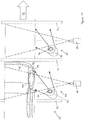
Figure 13 shows a schematic top view representation of an embodiment of a side wall imaging system 45 in accordance with aspects of the present invention. The imaging system 45 comprises afirst imaging section 46 and a second imaging section 47 for imaging a wheel on a vehicle 48 as it drives past. Thefirst imaging section 46 comprises a first camera 49 and first andsecond flash units 50, 51. - First camera 49 is positioned so that the top half 52 of the vehicle tyre 53 passes through the camera's field of view 54 as the vehicle 48 drives past.
- First and
second flash units 50, 51 are positioned to illuminate the side wall 55 of the vehicle tyre 53. The first flash unit 50 is positioned to illuminate a near end 56 of the tyre 53, whileflash unit 51 is positioned to illuminate a far side 57 of the tyre 53. Illumination across the tyre 53 while the vehicle 48 drives past can thus be achieved by activating bothside flash units 50, 51 at the same time. - The first and
second flash units 50, 51 are positioned to direct flashes of light on to the side wall 55 surface at an angle of approximately 40° to the vehicle direction of travel (shown by arrow 60). In variations on this embodiment, the angle of incidence of the light to the direction of travel is in therange 30° to 50°, although other angles are possible. - The illumination from the flashes causes shadows to be cast by embossed markings on the side wall 55 surface and by any damage in the side wall 55, such as cracks or bulges.
- A first sensor 58 detects when the vehicle is approaching the field of view 54 of the first camera 49, and then activates the
flash units 50, 51 and the camera 49 to begin the imaging process as the vehicle passes the sensor 58. A second sensor 59 detects when the vehicle has exited the field of view 54 of the first camera 49, and deactivates the first camera 49 and the first andsecond flash units 50, 51. - The first camera is positioned approximately 1.8 metres from the position of the vehicle tyre 53 when the system is in use. At this distance, the field of view of the camera is approximately 0.5 metres across. The first and second flash units are positioned approximately 0.5 metres and 0.2 metres respectively from the tyre when the system is in use. Having one side flash unit closer to the tyre than the other flash unit provides the advantage that the closer flash unit can illuminate tyres that are smaller and farther anyway.
- As the vehicle 48 continues in the direction of travel shown by the
arrow 60, the vehicle 48 moves into the second imaging section 47. The second imaging section 47 comprises a second camera 61 and third andfourth flash units 62, 63. These components are arranged in the same manner as the first camera 49 and the first andsecond flash units 50, 51 of thefirst imaging section 46, but laterally displaced in the direction of travel by approximately 1 metre. The second sensor 59, which detects that the vehicle has left thefirst imaging section 46, also serves to determine that the vehicle has entered the second imaging section 47. When this happens, the second camera 61, and the third andfourth flash units 62, 63, are activated in a similar manner to that described previously with reference to thefirst imaging section 46. - As the vehicle travels the distance between the first camera's field of view and the second camera's field of view, the tyre 53 rotates so that a different portion of the side wall 55 is positioned at the top of the tyre. Accordingly, the portion of the side wall 55 that is in the field of view of the second camera 61 is different from the portion that was in the field of view of the first camera 49. In this way, the second camera 61 is able to image a different portion of the side wall 55 from that imaged by the first camera 49.
- A third sensor 64 detects when the vehicle has moved out of the field of view of the second camera 61, and deactivates the second camera 61 and the third and
fourth flash units 62, 63 when the vehicle exits the second imaging section 47. - The cameras 49, 61 are JAI GigE GO-5000M-PGE cameras, which record at 23 frames per second, with a camera exposure of 200 microseconds at 5 megapixels, and use a 50mm lens (e.g. Kowa LM50HC-SW 14.50 horizontal view with 1" sensor). It will be appreciated that different cameras with other specifications could be used in this or in other embodiments.
-
Figure 14 shows an alternative embodiment of a side wall imaging system 65. The system 65 comprises a first imaging section 66 and asecond imaging section 67. The first andsecond imaging sections 66, 67 comprise respective first andsecond camera Figure 13 . The imaging system 65 also comprises first, second and third sensors, 70, 71, 72 which are arranged and function in the same manner as the sensors ofFigure 13 . The imaging system 65 functions in the same manner as the imaging system 45 ofFigure 13 to image the side wall 73 of a tyre 74 on a vehicle 75, except that only one flash unit is provided in each imaging section, i.e. there is one flash unit per camera. - First flash unit 76 in the first imaging section 66 is provided with a first parabolic reflector 77 and is positioned and angled so as to direct a beam of light onto the tyre 74 at an angle of incidence of approximately 35° to the vehicle's direction of travel as indicated by the arrow 78. In some other embodiments using parabolic reflectors, the angle of incidence is between 20° and 50°, although other angles are possible.
- The light beam produced by the first flash unit 76 is directed by the first parabolic reflector 77 towards a far end 79 of the tyre 74. This helps to produce a more even intensity of light over the side wall surface as the brightest part of the light beam is directed onto the farthest part of the tyre. The use of the parabolic reflector 77 means that the illumination provided by the single flash unit 76 is sufficient to illuminate the entire side wall. This is in contrast with the embodiment of
Figure 13 , where two flash units without parabolic reflectors are used to fully illuminate the portion of the side wall that is imaged by the camera. The parabolic reflector 77 also enables tyres that are smaller and/or farther away to be illuminated without the need for two side flash units per tyre. In other embodiments, e.g. the embodiment ofFigure 13 , this may be achieved by having a side flash unit positioned closer to the vehicle. - In the
second imaging section 67, a second flash unit 80 is provided, with a corresponding second parabolic reflector 81. The second flash unit 80 and second reflector 81 are arranged in the same position as the first flash unit 76 and the first reflector 77, except that they are displaced laterally approximately 1 metre in the direction of travel 78. Thesecond imaging section 67 thus operates in an equivalent manner to the first imaging section 66, but as the tyre has rotated due to the vehicle moving forward (as explained above), a different portion of the side wall 73 is imaged by thesecond camera 69. - The systems shown in
Figures 13 and14 may be combined with tread depth measuring systems and/or tyre pressure measuring systems, but other systems are omitted from these Figures for clarity. -
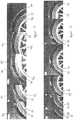
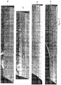
Figure 15 shows a series of images obtained using the first camera in the embodiment shown inFigure 14 . Each of the successive images shown inFigure 15 corresponds to a frame of the recording of the first camera. It will be appreciated that not all of the images captured by the camera are shown inFigure 15 , as the first camera records at 23 frames per second. The images selected represent a range of image capture times from the point at which the tyre enters the camera's field of view to the time that its leaves. - Each image in
Figure 15 shows the upper part of awheel 82 with itstyre 83 under thevehicle wheel arch 84. In the middle image thetext 85 "UNIROYAL" is visible, indicating that the tyre is of the Uniroyal™ brand. In the far left image ofFigure 15 , additional embossed markings are also visible, which can be read from the images using image analysis software. The data extracted from this text can be used to identify the tyre specification. -
Figure 16 shows a similar series of images taken using the second camera in the embodiment ofFigure 14 . Between the first and second cameras, the wheel has rotated as the vehicle moved forward and so the images ofFigure 16 show the portion of the side wall that is not visible in the images ofFigure 15 . -
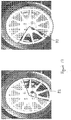
Figure 17 shows two images of thewheel 82 that has been imaged inFigure 15 and 16 . In the left image, a dotted line shows the major sector imaged by the first camera, as shown inFigure 15 . In the right image, a dotted line shows the major sector imaged by the second camera, as shown inFigure 16 . It can be seen from these images that the images of the first and second camera together cover the entire tyre side wall, with some overlap. -
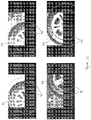
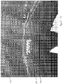
Figure 18 shows four example images, each of adifferent tyre Figure 14 . Image analysis software has been used to identify the tyre in the image and to extrapolate the position of the whole tyre. The extrapolated position is shown in each image usingwhite circles 90 which indicate the inner edge and periphery of the tyre. - Once the position of the tyre has been identified, the image software can be used to unwrap the tyre to show the entire side wall as a single elongate image. This is shown in
Figure 19 . The four images correspond to a respective tyre as shown inFigure 18 . Having an unwrapped image of the side wall can assist with assessment of side wall damage, as the entire side wall is visible in a single image. It can also assist with the extraction of data from embossed markings on the side wall, as in the unwrapped images, the text can be viewed upright in a rectilinear format, which may help with, for example, optical character recognition for reading the data. -
Figures 20 to 26 show example side wall images obtained using a system in accordance with the present invention. - In
Figure 20 , the top half of aside wall 91 has been imaged. In the image embossedtext 92 can be seen. The text has been illuminated by a flash of light from a flash unit so that the embossed text casts shadows, creating contrasting regions of shadow and light causing the text to be clearly visible in the image. Areflection 93 of the flash of light can be seen in the bodywork of the car. -
Figure 21 shows another example of aside wall 94 that has been imaged in accordance with the present invention. Again, embossedtext 95 can be seen on theside wall 94. -
Figure 22 shows a further example of aside wall 96 that has been imaged, with embossed text 97. On some of the side walls, there are also logos - for example, thelogo 98 visible inFigure 22 . Image analysis of logos, pictograms, and similar markings may also be carried out by image analysis software to identify a tyre or otherwise obtain information related to it. -
Figure 23 shows an example of an image of a side wall 99 of a tyre, where the side wall has been damaged. The damage is visible as cracking 100 in the region of a sidewall wear indicator 101. The wear indicator is provided in the tyre to provide an early indication that the thickness of the side wall is being reduced, and that a tyre will soon need to be replaced. -
Figure 24 shows another example of damage in theside wall 102 of a tyre. Cracking 103 is visible in the region of thetyre bead 104. -
Figure 25 shows an image of atyre side wall 105 showingdamage 106 resulting from retread failure, i.e. where replacement tread has been applied to a worn tyre to repair it, but the new tread has become detached from the tyre body. -
Figure 26 shows a further image of atyre side wall 107 showing a tyre zipper rupture, i.e. a circumferential rupture in the mid side wall of the tyre.
Claims (13)
- A method of assessing the condition of a tyre on a wheel (2) which is mounted on a vehicle (1), while the vehicle is moving and the tyre is rotating and moving longitudinally along a path of movement, the periphery of the tyre having tread portions separated by tread gaps; in which the method comprisesusing an imaging device (3) to capture images of a plurality of different portions of the periphery of the tyre whilst the tyre revolves,the images being captured whilst longitudinally spaced flash units (F1, F2, F3, F4) are activated to illuminate portions of the periphery of the tyre,the flash units being positioned to one side of the path of movement (A) of the tyre and directing light at an acute angle to the path of movement of the tyre, the light causing shadows to be cast in the tread gaps between tread portions;and the images are analysed by data processing apparatus which determines the extent of shadows in the tread gaps so as to provide an indication of the depth of the tread gaps;wherein each flash unit causes a series of flashes of light to be produced when the flash unit is activated, each flash of light in the series being separated from the next flash of light in the series by an interval;wherein for any flash units (F1, F2, F3, F4) which are activated at the same time and illuminate overlapping portions of the periphery of tyre, the respective series of flashes of light are out of phase so that the flashes of light from one flash unit are emitted in the intervals between the flashes of light from the or each other flash unit, and whereinthe capturing of the images is synchronised with the production of the respective flashes of light when the flash units (F1, F2, F3, F4) are activated.
- A method as claimed in claim 1, wherein each flash unit (F1, F2, F3, F4), when activated, produces a series of substantially identical pulses separated by intervals which are substantially identical.
- A method as claimed in claim 2, wherein the imaging device (3) captures images at a rate which is substantially double the rate at which pulses are produced when a flash unit is activated.
- A method as claimed in any preceding claim, where a control system sends triggers for issuing flashes from the flash units (F1, F2, F3, F4) and also triggers for causing the imaging device (3) to capture images.
- A method as claimed in any preceding claim, wherein a speed sensing system senses the speed of the vehicle and the rate at which flashes are issued by the flash units (F1, F2, F3, F4) and the rate at which images are captured by the imaging device (3) are varied in dependence on the speed of the vehicle.
- A method as claimed in claim 5, wherein the rate at which flashes are issued by the flash units (F1, F2, F3, F4) and the rate at which images are captured by the imaging device (3), are at a first value if the speed of the vehicle is below a predetermined speed, and at a second, higher, value if the speed of the vehicle is at or above the predetermined speed.
- A method as claimed in claim 5, wherein the rate at which flashes are issued by the flash units (F1, F2, F3, F4) and the rate at which images are captured by the imaging device (3), are directly related to the speed of the vehicle.
- A method as claimed in any preceding claim, wherein the imaging device (3) captures images whilst the tyre completes at least a major part of a complete revolution.
- A method as claimed in any preceding claim, further comprising imaging at least part of a side wall of the tyre using a plurality of longitudinally spaced side wall imaging devices to capture images of a plurality of different portions of the side wall of the tyre whilst the tyre revolves, the images being captured whilst longitudinally spaced side flash units are activated to illuminate portions of the side wall of the tyre, the side flash units being positioned to one side of the path of movement of the tyre and directing light onto the side wall of the tyre at an acute angle to the longitudinal path of movement, wherein each side flash unit causes a series of flashes of light to be produced when the side flash unit is activated, each flash of light in the series being separated from the next flash of light in the series by an interval.
- A system for assessing the condition of a tyre on a wheel which is mounted on a vehicle, while the vehicle is moving and the tyre is rotating and moving longitudinally along a path of movement, the periphery of the tyre having tread portions separated by tread gaps; the system comprising:longitudinally spaced flash units (F1, F2, F3, F4) positioned to one side of the path of movement of the tyre and directing light at an acute angle to the path of movement of the tyre, the light causing shadows to be cast in the tread gaps between tread portions;an imaging device (3) arranged to capture images of a plurality of different portions of the periphery of the tyre whilst the tyre revolves,the images being captured whilst the longitudinally spaced flash units are activated to illuminate portions of the periphery of the tyre; anda data processing apparatus arranged to analyse the images and determine the extent of shadows in the tread gaps so as to provide an indication of the depth of the tread gaps;wherein each flash unit causes a series of flashes of light to be produced when the flash unit is activated, each flash of light in the series being separated from the next flash of light in the series by an interval;wherein for any flash units (F1, F2, F3, F4) which are activated at the same time and illuminate overlapping portions of the periphery of tyre, the flash units are configured to emit the respective series of flashes of light out of phase so that the flashes of light from one flash unit are emitted in the intervals between the flashes of light from the or each other flash unit, and whereinthe image device (3) is configured to be synchronised with the production of the respective flashes of light when the flash units are activated.
- The system of claim 10, comprising a speed sensing system configured to sense a speed of the vehicle and a rate at which flashes are issued by the flash units (F1, F2, F3, F4),
wherein the imaging device (3) is configured to vary the rate at which images are captured in dependence on the speed of the vehicle. - The system of claim 11, wherein said rate at which flashes are issued by the flash units (F1, F2, F3, F4) and said rate at which images are captured by the imaging device (3), are at a first value if the speed of the vehicle is below a predetermined speed, and at a second, higher, value if the speed of the vehicle is at or above the predetermined speed.
- The system of claim 11, wherein said rate at which flashes are issued by the flash units and said rate at which images are captured by the imaging device (3), are directly related to the speed of the vehicle.
Priority Applications (2)
| Application Number | Priority Date | Filing Date | Title |
|---|---|---|---|
| EP19151458.7A EP3489623A1 (en) | 2015-10-09 | 2016-10-10 | Method and system for imaging a side wall of a tyre |
| PL16781192T PL3359912T3 (en) | 2015-10-09 | 2016-10-10 | Method and system for tyre condition analysis |
Applications Claiming Priority (2)
| Application Number | Priority Date | Filing Date | Title |
|---|---|---|---|
| GBGB1517926.0A GB201517926D0 (en) | 2015-10-09 | 2015-10-09 | Tyre condition analysis |
| PCT/GB2016/053148 WO2017060739A1 (en) | 2015-10-09 | 2016-10-10 | Tyre condition analysis |
Related Child Applications (2)
| Application Number | Title | Priority Date | Filing Date |
|---|---|---|---|
| EP19151458.7A Division-Into EP3489623A1 (en) | 2015-10-09 | 2016-10-10 | Method and system for imaging a side wall of a tyre |
| EP19151458.7A Division EP3489623A1 (en) | 2015-10-09 | 2016-10-10 | Method and system for imaging a side wall of a tyre |
Publications (2)
| Publication Number | Publication Date |
|---|---|
| EP3359912A1 EP3359912A1 (en) | 2018-08-15 |
| EP3359912B1 true EP3359912B1 (en) | 2020-01-01 |
Family
ID=55130846
Family Applications (2)
| Application Number | Title | Priority Date | Filing Date |
|---|---|---|---|
| EP16781192.6A Active EP3359912B1 (en) | 2015-10-09 | 2016-10-10 | Method and system for tyre condition analysis |
| EP19151458.7A Withdrawn EP3489623A1 (en) | 2015-10-09 | 2016-10-10 | Method and system for imaging a side wall of a tyre |
Family Applications After (1)
| Application Number | Title | Priority Date | Filing Date |
|---|---|---|---|
| EP19151458.7A Withdrawn EP3489623A1 (en) | 2015-10-09 | 2016-10-10 | Method and system for imaging a side wall of a tyre |
Country Status (14)
| Country | Link |
|---|---|
| US (1) | US10605697B2 (en) |
| EP (2) | EP3359912B1 (en) |
| JP (1) | JP6765728B2 (en) |
| KR (1) | KR102578773B1 (en) |
| CN (1) | CN108369088B (en) |
| AU (1) | AU2016335369B2 (en) |
| BR (1) | BR112018006997B1 (en) |
| CA (1) | CA3000974C (en) |
| ES (1) | ES2773106T3 (en) |
| GB (1) | GB201517926D0 (en) |
| HK (1) | HK1251292A1 (en) |
| PL (1) | PL3359912T3 (en) |
| WO (1) | WO2017060739A1 (en) |
| ZA (1) | ZA201803052B (en) |
Families Citing this family (23)
| Publication number | Priority date | Publication date | Assignee | Title |
|---|---|---|---|---|
| MX2017007772A (en) | 2014-12-22 | 2017-10-02 | Pirelli | Method and apparatus for checking tyres in a production line. |
| EP3237834B1 (en) * | 2014-12-22 | 2020-02-19 | Pirelli Tyre S.p.A. | Apparatus for controlling tyres in a production line |
| US10670497B2 (en) * | 2015-12-16 | 2020-06-02 | Pirelli Tyre S.P.A | Device and method for analysis of tyres comprising first and second image acquistion systems |
| US10605698B2 (en) | 2015-12-16 | 2020-03-31 | Pirelli Tyre S.P.A. | Method and apparatus for checking tyres |
| MX2018008102A (en) | 2015-12-28 | 2018-12-17 | Pirelli | Apparatus and method for checking tyres. |
| CN108603813B (en) | 2015-12-28 | 2020-10-27 | 倍耐力轮胎股份公司 | Apparatus for inspecting tyres |
| ITUA20162722A1 (en) * | 2016-04-19 | 2017-10-19 | Butler Eng And Marketing S P A | DEVICE AND METHOD FOR ANALYSIS AND DETECTION OF GEOMETRIC CHARACTERISTICS OF AN OBJECT |
| JP6898673B2 (en) * | 2017-02-13 | 2021-07-07 | ホイールライト・リミテッドWheelright Limited | Tread wire scanner |
| GB201706800D0 (en) * | 2017-04-28 | 2017-06-14 | Gould Daniel George | Method and apparatus for vehicle damage mapping |
| IT201800004673A1 (en) * | 2018-04-18 | 2019-10-18 | PROCEDURE AND SYSTEM FOR DETECTION OF DEFECTS IN A TIRE | |
| JP7030614B2 (en) | 2018-05-25 | 2022-03-07 | 株式会社ブリヂストン | Tire condition management system and tire condition management program |
| JP6985979B2 (en) * | 2018-05-25 | 2021-12-22 | 株式会社ブリヂストン | Tire condition estimation system and tire condition estimation program |
| GB2580675A (en) | 2019-01-23 | 2020-07-29 | Wheelright Ltd | Tyre sidewall imaging method |
| GB2585633B (en) | 2019-05-14 | 2021-09-22 | Wheelright Ltd | Tyre sidewall imaging method |
| US11614380B2 (en) | 2019-07-02 | 2023-03-28 | Hunter Engineering Company | System and method for acquisition of tire sidewall data from a moving vehicle |
| US11338621B2 (en) | 2019-11-26 | 2022-05-24 | Hunter Engineering Company | Drive-over tire tread measurement system for heavy-duty multi-axle vehicles |
| CN110843428B (en) * | 2019-12-23 | 2024-06-04 | 吉林大学 | Device for detecting damage of inner side of tire of vehicle-mounted tire based on image recognition |
| JP7445117B2 (en) * | 2019-12-26 | 2024-03-07 | 横浜ゴム株式会社 | Tire wear degree determination device, tire wear degree determination method and program |
| US20230106441A1 (en) * | 2020-02-21 | 2023-04-06 | Tyrata, Inc. | Magnetic drive-over system providing tire tread thickness/depth measurement |
| US11562472B2 (en) | 2020-09-30 | 2023-01-24 | Uveye Ltd. | System of tread depth estimation and method thereof |
| US20220114756A1 (en) * | 2020-10-13 | 2022-04-14 | Autobrains Technologies Ltd | Camera based distance measurements |
| JP7435822B2 (en) | 2020-11-10 | 2024-02-21 | 株式会社村田製作所 | tire observation device |
| JP2023039726A (en) * | 2021-09-09 | 2023-03-22 | Toyo Tire株式会社 | Tire groove depth display method and tire groove depth display device |
Family Cites Families (14)
| Publication number | Priority date | Publication date | Assignee | Title |
|---|---|---|---|---|
| SE368736B (en) * | 1972-10-25 | 1974-07-15 | Hernsjoe Handels Ab | |
| US5987978A (en) * | 1997-04-02 | 1999-11-23 | Assembly Technology & Test Ltd. | Apparatus for testing tire tread depth |
| US6560883B2 (en) | 2000-06-28 | 2003-05-13 | Snap-On Technologies, Inc. | Method and system for conducting wheel alignment |
| DE102004050355A1 (en) | 2004-10-15 | 2006-04-27 | Steinbichler Optotechnik Gmbh | Method and device for testing the surface of a tire |
| US7107138B2 (en) * | 2004-11-02 | 2006-09-12 | Joseph Edward Currie | Automotive speed control disable switch |
| EP1845338B1 (en) * | 2006-04-13 | 2013-07-17 | Snap-on Equipment Srl a unico socio | Method of optically scanning the tread surface of a pneumatic tyre of a vehicle wheel |
| JP4480773B2 (en) * | 2008-04-01 | 2010-06-16 | トヨタ自動車株式会社 | Tire type discrimination method, and vehicle inspection method and apparatus using the same |
| US7975540B2 (en) | 2008-04-24 | 2011-07-12 | Rite-Solutions, Inc. | Methods and apparatus for tire tread measurement |
| EP2141475B1 (en) * | 2008-07-03 | 2013-03-27 | Snap-on Equipment Srl a unico socio | Apparatus for determining the condition of a tire tread of a vehicle wheel |
| DE102009016498A1 (en) * | 2009-04-08 | 2010-10-21 | Ventech Gmbh | Method and device for determining the tread depth of a vehicle tire |
| US8542881B2 (en) * | 2010-07-26 | 2013-09-24 | Nascent Technology, Llc | Computer vision aided automated tire inspection system for in-motion inspection of vehicle tires |
| WO2014117870A1 (en) * | 2013-02-04 | 2014-08-07 | Me-Inspection Sk | Method, measuring arrangement and system for inspecting a 3-dimensional object |
| DE102013207374A1 (en) | 2013-04-23 | 2014-10-23 | Robert Bosch Gmbh | Device and method for recognizing labels on vehicle tires |
| GB201318824D0 (en) * | 2013-10-24 | 2013-12-11 | Wheelright Ltd | Tyre condition analysis |
-
2015
- 2015-10-09 GB GBGB1517926.0A patent/GB201517926D0/en not_active Ceased
-
2016
- 2016-10-10 BR BR112018006997-3A patent/BR112018006997B1/en active IP Right Grant
- 2016-10-10 CA CA3000974A patent/CA3000974C/en active Active
- 2016-10-10 CN CN201680072212.8A patent/CN108369088B/en active Active
- 2016-10-10 AU AU2016335369A patent/AU2016335369B2/en active Active
- 2016-10-10 EP EP16781192.6A patent/EP3359912B1/en active Active
- 2016-10-10 WO PCT/GB2016/053148 patent/WO2017060739A1/en active Application Filing
- 2016-10-10 US US15/766,739 patent/US10605697B2/en active Active
- 2016-10-10 ES ES16781192T patent/ES2773106T3/en active Active
- 2016-10-10 JP JP2018516835A patent/JP6765728B2/en active Active
- 2016-10-10 KR KR1020187013114A patent/KR102578773B1/en active IP Right Grant
- 2016-10-10 EP EP19151458.7A patent/EP3489623A1/en not_active Withdrawn
- 2016-10-10 PL PL16781192T patent/PL3359912T3/en unknown
-
2018
- 2018-05-09 ZA ZA2018/03052A patent/ZA201803052B/en unknown
- 2018-08-16 HK HK18110531.5A patent/HK1251292A1/en unknown
Non-Patent Citations (1)
| Title |
|---|
| None * |
Also Published As
| Publication number | Publication date |
|---|---|
| ZA201803052B (en) | 2023-12-20 |
| US10605697B2 (en) | 2020-03-31 |
| JP6765728B2 (en) | 2020-10-07 |
| CA3000974A1 (en) | 2017-04-13 |
| HK1251292A1 (en) | 2019-01-25 |
| AU2016335369A1 (en) | 2018-05-24 |
| PL3359912T3 (en) | 2020-07-13 |
| AU2016335369B2 (en) | 2020-12-10 |
| GB201517926D0 (en) | 2015-11-25 |
| US20180299352A1 (en) | 2018-10-18 |
| BR112018006997A2 (en) | 2018-10-16 |
| EP3489623A1 (en) | 2019-05-29 |
| EP3359912A1 (en) | 2018-08-15 |
| WO2017060739A1 (en) | 2017-04-13 |
| BR112018006997B1 (en) | 2022-10-11 |
| ES2773106T3 (en) | 2020-07-09 |
| CN108369088A (en) | 2018-08-03 |
| KR20180071285A (en) | 2018-06-27 |
| KR102578773B1 (en) | 2023-09-15 |
| CN108369088B (en) | 2020-05-08 |
| CA3000974C (en) | 2023-10-10 |
| JP2018537655A (en) | 2018-12-20 |
Similar Documents
| Publication | Publication Date | Title |
|---|---|---|
| EP3359912B1 (en) | Method and system for tyre condition analysis | |
| CN110057601B (en) | Method and apparatus for tire condition analysis | |
| US8621919B2 (en) | Method and apparatus for determining the tread depth of a vehicle tire | |
| JP3464678B2 (en) | Apparatus and method for evaluating tire condition | |
| JP7536259B2 (en) | Assembly to detect defects in automotive body structure | |
| CN103038601A (en) | Device and method for inspecting tyre shape | |
| US11338621B2 (en) | Drive-over tire tread measurement system for heavy-duty multi-axle vehicles | |
| JP2014081356A (en) | Vehicle body visual inspection device and visual inspection method | |
| US10324005B2 (en) | Method and device for checking the tire mounting on a vehicle | |
| CN216846130U (en) | Tire pattern depth measurement system | |
| CN110658004A (en) | Method for testing a tyre | |
| CN114562952A (en) | Tire pattern depth measuring method, and all-round pattern depth measuring method and system | |
| KR20200042623A (en) | Tire tread defect detection device |
Legal Events
| Date | Code | Title | Description |
|---|---|---|---|
| STAA | Information on the status of an ep patent application or granted ep patent |
Free format text: STATUS: THE INTERNATIONAL PUBLICATION HAS BEEN MADE |
|
| PUAI | Public reference made under article 153(3) epc to a published international application that has entered the european phase |
Free format text: ORIGINAL CODE: 0009012 |
|
| STAA | Information on the status of an ep patent application or granted ep patent |
Free format text: STATUS: REQUEST FOR EXAMINATION WAS MADE |
|
| 17P | Request for examination filed |
Effective date: 20180501 |
|
| AK | Designated contracting states |
Kind code of ref document: A1 Designated state(s): AL AT BE BG CH CY CZ DE DK EE ES FI FR GB GR HR HU IE IS IT LI LT LU LV MC MK MT NL NO PL PT RO RS SE SI SK SM TR |
|
| AX | Request for extension of the european patent |
Extension state: BA ME |
|
| DAV | Request for validation of the european patent (deleted) | ||
| DAX | Request for extension of the european patent (deleted) | ||
| REG | Reference to a national code |
Ref country code: HK Ref legal event code: DE Ref document number: 1251292 Country of ref document: HK |
|
| STAA | Information on the status of an ep patent application or granted ep patent |
Free format text: STATUS: EXAMINATION IS IN PROGRESS |
|
| 17Q | First examination report despatched |
Effective date: 20190124 |
|
| REG | Reference to a national code |
Ref country code: DE Ref legal event code: R079 Ref document number: 602016027409 Country of ref document: DE Free format text: PREVIOUS MAIN CLASS: G01B0011060000 Ipc: G01B0011240000 |
|
| GRAP | Despatch of communication of intention to grant a patent |
Free format text: ORIGINAL CODE: EPIDOSNIGR1 |
|
| STAA | Information on the status of an ep patent application or granted ep patent |
Free format text: STATUS: GRANT OF PATENT IS INTENDED |
|
| RIC1 | Information provided on ipc code assigned before grant |
Ipc: G01M 17/02 20060101ALI20190624BHEP Ipc: G01B 11/24 20060101AFI20190624BHEP Ipc: B60C 11/24 20060101ALI20190624BHEP |
|
| INTG | Intention to grant announced |
Effective date: 20190711 |
|
| GRAS | Grant fee paid |
Free format text: ORIGINAL CODE: EPIDOSNIGR3 |
|
| GRAA | (expected) grant |
Free format text: ORIGINAL CODE: 0009210 |
|
| STAA | Information on the status of an ep patent application or granted ep patent |
Free format text: STATUS: THE PATENT HAS BEEN GRANTED |
|
| AK | Designated contracting states |
Kind code of ref document: B1 Designated state(s): AL AT BE BG CH CY CZ DE DK EE ES FI FR GB GR HR HU IE IS IT LI LT LU LV MC MK MT NL NO PL PT RO RS SE SI SK SM TR |
|
| REG | Reference to a national code |
Ref country code: GB Ref legal event code: FG4D |
|
| REG | Reference to a national code |
Ref country code: CH Ref legal event code: EP Ref country code: AT Ref legal event code: REF Ref document number: 1220299 Country of ref document: AT Kind code of ref document: T Effective date: 20200115 |
|
| REG | Reference to a national code |
Ref country code: IE Ref legal event code: FG4D |
|
| REG | Reference to a national code |
Ref country code: DE Ref legal event code: R096 Ref document number: 602016027409 Country of ref document: DE |
|
| REG | Reference to a national code |
Ref country code: CH Ref legal event code: NV Representative=s name: SERVOPATENT GMBH, CH |
|
| REG | Reference to a national code |
Ref country code: NL Ref legal event code: FP |
|
| REG | Reference to a national code |
Ref country code: CH Ref legal event code: PCAR Free format text: NEW ADDRESS: WANNERSTRASSE 9/1, 8045 ZUERICH (CH) |
|
| REG | Reference to a national code |
Ref country code: ES Ref legal event code: FG2A Ref document number: 2773106 Country of ref document: ES Kind code of ref document: T3 Effective date: 20200709 |
|
| REG | Reference to a national code |
Ref country code: LT Ref legal event code: MG4D |
|
| PG25 | Lapsed in a contracting state [announced via postgrant information from national office to epo] |
Ref country code: RS Free format text: LAPSE BECAUSE OF FAILURE TO SUBMIT A TRANSLATION OF THE DESCRIPTION OR TO PAY THE FEE WITHIN THE PRESCRIBED TIME-LIMIT Effective date: 20200101 Ref country code: NO Free format text: LAPSE BECAUSE OF FAILURE TO SUBMIT A TRANSLATION OF THE DESCRIPTION OR TO PAY THE FEE WITHIN THE PRESCRIBED TIME-LIMIT Effective date: 20200401 Ref country code: FI Free format text: LAPSE BECAUSE OF FAILURE TO SUBMIT A TRANSLATION OF THE DESCRIPTION OR TO PAY THE FEE WITHIN THE PRESCRIBED TIME-LIMIT Effective date: 20200101 Ref country code: PT Free format text: LAPSE BECAUSE OF FAILURE TO SUBMIT A TRANSLATION OF THE DESCRIPTION OR TO PAY THE FEE WITHIN THE PRESCRIBED TIME-LIMIT Effective date: 20200527 Ref country code: LT Free format text: LAPSE BECAUSE OF FAILURE TO SUBMIT A TRANSLATION OF THE DESCRIPTION OR TO PAY THE FEE WITHIN THE PRESCRIBED TIME-LIMIT Effective date: 20200101 |
|
| PG25 | Lapsed in a contracting state [announced via postgrant information from national office to epo] |
Ref country code: IS Free format text: LAPSE BECAUSE OF FAILURE TO SUBMIT A TRANSLATION OF THE DESCRIPTION OR TO PAY THE FEE WITHIN THE PRESCRIBED TIME-LIMIT Effective date: 20200501 Ref country code: BG Free format text: LAPSE BECAUSE OF FAILURE TO SUBMIT A TRANSLATION OF THE DESCRIPTION OR TO PAY THE FEE WITHIN THE PRESCRIBED TIME-LIMIT Effective date: 20200401 Ref country code: SE Free format text: LAPSE BECAUSE OF FAILURE TO SUBMIT A TRANSLATION OF THE DESCRIPTION OR TO PAY THE FEE WITHIN THE PRESCRIBED TIME-LIMIT Effective date: 20200101 Ref country code: LV Free format text: LAPSE BECAUSE OF FAILURE TO SUBMIT A TRANSLATION OF THE DESCRIPTION OR TO PAY THE FEE WITHIN THE PRESCRIBED TIME-LIMIT Effective date: 20200101 Ref country code: GR Free format text: LAPSE BECAUSE OF FAILURE TO SUBMIT A TRANSLATION OF THE DESCRIPTION OR TO PAY THE FEE WITHIN THE PRESCRIBED TIME-LIMIT Effective date: 20200402 Ref country code: HR Free format text: LAPSE BECAUSE OF FAILURE TO SUBMIT A TRANSLATION OF THE DESCRIPTION OR TO PAY THE FEE WITHIN THE PRESCRIBED TIME-LIMIT Effective date: 20200101 |
|
| REG | Reference to a national code |
Ref country code: DE Ref legal event code: R097 Ref document number: 602016027409 Country of ref document: DE |
|
| PG25 | Lapsed in a contracting state [announced via postgrant information from national office to epo] |
Ref country code: DK Free format text: LAPSE BECAUSE OF FAILURE TO SUBMIT A TRANSLATION OF THE DESCRIPTION OR TO PAY THE FEE WITHIN THE PRESCRIBED TIME-LIMIT Effective date: 20200101 Ref country code: SM Free format text: LAPSE BECAUSE OF FAILURE TO SUBMIT A TRANSLATION OF THE DESCRIPTION OR TO PAY THE FEE WITHIN THE PRESCRIBED TIME-LIMIT Effective date: 20200101 Ref country code: EE Free format text: LAPSE BECAUSE OF FAILURE TO SUBMIT A TRANSLATION OF THE DESCRIPTION OR TO PAY THE FEE WITHIN THE PRESCRIBED TIME-LIMIT Effective date: 20200101 Ref country code: SK Free format text: LAPSE BECAUSE OF FAILURE TO SUBMIT A TRANSLATION OF THE DESCRIPTION OR TO PAY THE FEE WITHIN THE PRESCRIBED TIME-LIMIT Effective date: 20200101 Ref country code: RO Free format text: LAPSE BECAUSE OF FAILURE TO SUBMIT A TRANSLATION OF THE DESCRIPTION OR TO PAY THE FEE WITHIN THE PRESCRIBED TIME-LIMIT Effective date: 20200101 |
|
| PLBE | No opposition filed within time limit |
Free format text: ORIGINAL CODE: 0009261 |
|
| STAA | Information on the status of an ep patent application or granted ep patent |
Free format text: STATUS: NO OPPOSITION FILED WITHIN TIME LIMIT |
|
| REG | Reference to a national code |
Ref country code: AT Ref legal event code: MK05 Ref document number: 1220299 Country of ref document: AT Kind code of ref document: T Effective date: 20200101 |
|
| 26N | No opposition filed |
Effective date: 20201002 |
|
| PG25 | Lapsed in a contracting state [announced via postgrant information from national office to epo] |
Ref country code: AT Free format text: LAPSE BECAUSE OF FAILURE TO SUBMIT A TRANSLATION OF THE DESCRIPTION OR TO PAY THE FEE WITHIN THE PRESCRIBED TIME-LIMIT Effective date: 20200101 |
|
| PG25 | Lapsed in a contracting state [announced via postgrant information from national office to epo] |
Ref country code: SI Free format text: LAPSE BECAUSE OF FAILURE TO SUBMIT A TRANSLATION OF THE DESCRIPTION OR TO PAY THE FEE WITHIN THE PRESCRIBED TIME-LIMIT Effective date: 20200101 |
|
| PG25 | Lapsed in a contracting state [announced via postgrant information from national office to epo] |
Ref country code: MC Free format text: LAPSE BECAUSE OF FAILURE TO SUBMIT A TRANSLATION OF THE DESCRIPTION OR TO PAY THE FEE WITHIN THE PRESCRIBED TIME-LIMIT Effective date: 20200101 |
|
| REG | Reference to a national code |
Ref country code: BE Ref legal event code: MM Effective date: 20201031 |
|
| PG25 | Lapsed in a contracting state [announced via postgrant information from national office to epo] |
Ref country code: BE Free format text: LAPSE BECAUSE OF NON-PAYMENT OF DUE FEES Effective date: 20201031 |
|
| PG25 | Lapsed in a contracting state [announced via postgrant information from national office to epo] |
Ref country code: MT Free format text: LAPSE BECAUSE OF FAILURE TO SUBMIT A TRANSLATION OF THE DESCRIPTION OR TO PAY THE FEE WITHIN THE PRESCRIBED TIME-LIMIT Effective date: 20200101 Ref country code: CY Free format text: LAPSE BECAUSE OF FAILURE TO SUBMIT A TRANSLATION OF THE DESCRIPTION OR TO PAY THE FEE WITHIN THE PRESCRIBED TIME-LIMIT Effective date: 20200101 |
|
| PG25 | Lapsed in a contracting state [announced via postgrant information from national office to epo] |
Ref country code: MK Free format text: LAPSE BECAUSE OF FAILURE TO SUBMIT A TRANSLATION OF THE DESCRIPTION OR TO PAY THE FEE WITHIN THE PRESCRIBED TIME-LIMIT Effective date: 20200101 Ref country code: AL Free format text: LAPSE BECAUSE OF FAILURE TO SUBMIT A TRANSLATION OF THE DESCRIPTION OR TO PAY THE FEE WITHIN THE PRESCRIBED TIME-LIMIT Effective date: 20200101 |
|
| P01 | Opt-out of the competence of the unified patent court (upc) registered |
Effective date: 20230603 |
|
| PGFP | Annual fee paid to national office [announced via postgrant information from national office to epo] |
Ref country code: NL Payment date: 20231019 Year of fee payment: 8 |
|
| PGFP | Annual fee paid to national office [announced via postgrant information from national office to epo] |
Ref country code: LU Payment date: 20231019 Year of fee payment: 8 |
|
| PGFP | Annual fee paid to national office [announced via postgrant information from national office to epo] |
Ref country code: GB Payment date: 20231020 Year of fee payment: 8 |
|
| PGFP | Annual fee paid to national office [announced via postgrant information from national office to epo] |
Ref country code: ES Payment date: 20231227 Year of fee payment: 8 |
|
| PGFP | Annual fee paid to national office [announced via postgrant information from national office to epo] |
Ref country code: TR Payment date: 20231009 Year of fee payment: 8 Ref country code: IT Payment date: 20231020 Year of fee payment: 8 Ref country code: IE Payment date: 20231023 Year of fee payment: 8 Ref country code: FR Payment date: 20231026 Year of fee payment: 8 Ref country code: DE Payment date: 20231020 Year of fee payment: 8 Ref country code: CZ Payment date: 20230929 Year of fee payment: 8 Ref country code: CH Payment date: 20231102 Year of fee payment: 8 |
|
| PGFP | Annual fee paid to national office [announced via postgrant information from national office to epo] |
Ref country code: PL Payment date: 20231002 Year of fee payment: 8 |