EP3359899B1 - Multi-stage cement calcining plant suspension preheater - Google Patents
Multi-stage cement calcining plant suspension preheater Download PDFInfo
- Publication number
- EP3359899B1 EP3359899B1 EP16777698.8A EP16777698A EP3359899B1 EP 3359899 B1 EP3359899 B1 EP 3359899B1 EP 16777698 A EP16777698 A EP 16777698A EP 3359899 B1 EP3359899 B1 EP 3359899B1
- Authority
- EP
- European Patent Office
- Prior art keywords
- separator
- housing
- top separator
- material feed
- preheater
- Prior art date
- Legal status (The legal status is an assumption and is not a legal conclusion. Google has not performed a legal analysis and makes no representation as to the accuracy of the status listed.)
- Active
Links
- 239000004568 cement Substances 0.000 title claims description 54
- 239000000725 suspension Substances 0.000 title claims description 40
- 238000001354 calcination Methods 0.000 title claims description 34
- 239000000463 material Substances 0.000 claims description 200
- 238000003892 spreading Methods 0.000 claims description 50
- 235000012054 meals Nutrition 0.000 claims description 36
- 238000007599 discharging Methods 0.000 claims description 5
- 230000003247 decreasing effect Effects 0.000 claims description 3
- 239000007789 gas Substances 0.000 description 28
- JTJMJGYZQZDUJJ-UHFFFAOYSA-N phencyclidine Chemical class C1CCCCN1C1(C=2C=CC=CC=2)CCCCC1 JTJMJGYZQZDUJJ-UHFFFAOYSA-N 0.000 description 13
- 238000010276 construction Methods 0.000 description 12
- 239000002245 particle Substances 0.000 description 12
- 230000008901 benefit Effects 0.000 description 9
- 239000012530 fluid Substances 0.000 description 6
- 239000011343 solid material Substances 0.000 description 5
- 238000004519 manufacturing process Methods 0.000 description 4
- 238000000034 method Methods 0.000 description 4
- 238000000926 separation method Methods 0.000 description 4
- 238000009826 distribution Methods 0.000 description 2
- 239000007787 solid Substances 0.000 description 2
- 230000000694 effects Effects 0.000 description 1
- 238000012423 maintenance Methods 0.000 description 1
- 239000000203 mixture Substances 0.000 description 1
- 239000002994 raw material Substances 0.000 description 1
Images


Classifications
-
- F—MECHANICAL ENGINEERING; LIGHTING; HEATING; WEAPONS; BLASTING
- F27—FURNACES; KILNS; OVENS; RETORTS
- F27B—FURNACES, KILNS, OVENS, OR RETORTS IN GENERAL; OPEN SINTERING OR LIKE APPARATUS
- F27B7/00—Rotary-drum furnaces, i.e. horizontal or slightly inclined
- F27B7/20—Details, accessories, or equipment peculiar to rotary-drum furnaces
- F27B7/2016—Arrangements of preheating devices for the charge
- F27B7/2025—Arrangements of preheating devices for the charge consisting of a single string of cyclones
- F27B7/2033—Arrangements of preheating devices for the charge consisting of a single string of cyclones with means for precalcining the raw material
-
- F—MECHANICAL ENGINEERING; LIGHTING; HEATING; WEAPONS; BLASTING
- F27—FURNACES; KILNS; OVENS; RETORTS
- F27B—FURNACES, KILNS, OVENS, OR RETORTS IN GENERAL; OPEN SINTERING OR LIKE APPARATUS
- F27B15/00—Fluidised-bed furnaces; Other furnaces using or treating finely-divided materials in dispersion
- F27B15/003—Cyclones or chain of cyclones
-
- F—MECHANICAL ENGINEERING; LIGHTING; HEATING; WEAPONS; BLASTING
- F27—FURNACES; KILNS; OVENS; RETORTS
- F27B—FURNACES, KILNS, OVENS, OR RETORTS IN GENERAL; OPEN SINTERING OR LIKE APPARATUS
- F27B7/00—Rotary-drum furnaces, i.e. horizontal or slightly inclined
- F27B7/20—Details, accessories, or equipment peculiar to rotary-drum furnaces
- F27B7/2016—Arrangements of preheating devices for the charge
-
- F—MECHANICAL ENGINEERING; LIGHTING; HEATING; WEAPONS; BLASTING
- F27—FURNACES; KILNS; OVENS; RETORTS
- F27D—DETAILS OR ACCESSORIES OF FURNACES, KILNS, OVENS, OR RETORTS, IN SO FAR AS THEY ARE OF KINDS OCCURRING IN MORE THAN ONE KIND OF FURNACE
- F27D17/00—Arrangements for using waste heat; Arrangements for using, or disposing of, waste gases
- F27D17/004—Systems for reclaiming waste heat
-
- F—MECHANICAL ENGINEERING; LIGHTING; HEATING; WEAPONS; BLASTING
- F27—FURNACES; KILNS; OVENS; RETORTS
- F27D—DETAILS OR ACCESSORIES OF FURNACES, KILNS, OVENS, OR RETORTS, IN SO FAR AS THEY ARE OF KINDS OCCURRING IN MORE THAN ONE KIND OF FURNACE
- F27D17/00—Arrangements for using waste heat; Arrangements for using, or disposing of, waste gases
- F27D2017/009—Cyclone for separating fines from gas
Definitions
- the present invention relates to a multi-stage cement calcining plant suspension preheater for preheating the cement raw meal prior to its being burned in a kiln into cement clinker which is subsequently cooled in a clinker cooler.
- the preheater comprises a top separator comprising a central tube entering the top separator in a lowermost part of the separator housing whereas the central tubes of the bottom separators enters the separator housing in an upper part of the separator housing.
- the invention relates to a method of installing a top separator of the aforementioned kind.
- the invention relates to a top separator comprising a material feed inlet arranged in a central part of the upper part of the top separator housing.
- cyclone preheater for preheating the cement raw meal prior to its being burned in a kiln into cement clinker which is subsequently cooled in a clinker cooler.
- a cyclone preheater comprising four to six cyclone stages is used arranged in a preheater tower construction.
- the raw meal is introduced in the first cyclone stage and heated by direct contact with hot exhaust gases from the kiln according to the counter flow principle.
- Preheaters of this kind are generally known from the patent literature and one example is provided in EP 0 455 301 .
- a cyclone stage completely filled with compacted raw mill adds several tons to the empty weight of the cyclone and thereby to the preheater tower construction.
- the construction When dimensioning a preheater tower, the construction must typically be dimensioned according to worst case scenarios. Typically the maximum filling level of the cyclones is a critical parameter. All preheater towers are dimensioned to accommodate even critical situations when filling levels become close to the worst-case scenario e.g. due to clogging.
- Another aspect also that makes it necessary to build these very high towers is the need for high production rates with high temperature differences. Maintaining high production rates at high temperature differences require optimal heat exchange between air and raw meal material.
- BE698006A discloses a device for exchanging heat or material between a fine grained or powdered solid material and a gas.
- the device comprises a shaft in which the gas is swirled upwardly; means for introducing the solid material into a central zone of the gas flow in an upper region of the shaft; a series of conduits located externally of the shaft and each disposed so as to receive solid material carried upwardly and outwardly from a central gas flow zone and to direct this solid material into the central gas flow below the entrance to the next lower conduit.
- the shaft being of smaller cross-section at each zone of solid introduction into said gas flow than at zones where the solid enters the conduits.
- US5131462A discloses a heat exchanger in the form of a vessel for heat exchange of a pulverulent solid material and a gas, e.g. for preheating raw materials prior to a burning process by use of the hot exit gases fed to the vessel; consists of a hollow cylindrical central part with a tangential gas inlet, a conical base with a material outlet, and a downwardly orientated gas out, a concave upper part facing the central part and with at least one material inlet.
- the downwardly orientated gas outlet is mounted initially axially as a central pipe inside the vessel and is provided with a skirt; the height of the upper part, the distance of the material inlet from the vertical axis of the heat exchanger and the inclination of the inlet to the horizontal plane, the height of the central pipe gas inlet above the lower end level of the central part of the vessel and the inclination of the skirt are all dimensioned so as to provide optimum conditions, partly for heat exchange in radial counter current between material and gas, partly for separation of material from gas inside the vessel due to the downwardly orientated axial and tangential gas velocities.
- JPS60161762A discloses a particle separation apparatus to efficiently separate particles with a particle size equal to or more than a cut size, by providing an intermediate fluid discharge pipe opened to the conical part of a cyclone main body and making it possible to discharge particles with a particle size of below the cut size contained in a fluid.
- Particles in the fluid supplied into a main body cylindrical part from a fluid introducing pipe in a tangential direction are revolved and fallen to be arranged at every particle size from the wall side of the cylindrical part toward the center direction thereof.
- small diameter particles are discharged while sucked into the suction port of the intermediate fluid discharge pipe provided in the main body conical part while large diameter particles are fallen along the main body conical part and discharged from a conc. fluid discharge pipe.
- US4997363 is a further example of a multi-stage cement calcining plant suspension preheater known in the technical field.
- the preheater comprises a top separator comprising a central tube entering the top separator in a lowermost part of the separator housing whereas the central tubes of the bottom separators enters the separator housing in an upper part of the separator housing.
- Another object of the present invention is to provide an improved multi-stage cement calcining plant suspension preheater of the kind mentioned in the introduction, wherein the preheater comprises a top separator comprising a central tube entering the top separator in a lowermost part of the separator housing whereas the central tubes of the bottom separators enters the separator housing in an upper part of the separator housing, and wherein the top separator comprises a material feed inlet arranged in a central part of the upper part of the top separator housing.
- a preheater comprises a plurality of stages each of which has a separator for separating raw cement meal from a gas in which the meal is suspended and wherein the separators of said plurality of stages are serially connected and in series with a calcining combustor.
- the plurality of stages comprises a top separator arranged at the uppermost stage of the preheater and a plurality of bottom separators arranged at the lowermost stages of the preheater, where the separators comprise a separator housing comprising a substantially cylindrical upper part and a substantially conical lower part, a tangential inlet in the upper part of the separator housing for introducing an un-separated stream of gas and raw cement meal in suspension, an outlet in a lowermost end of the conical part for discharging a first fraction of coarse cement raw meal material, a central tube extending with a free end axially into the separator housing for diverting a second fraction of fine cement raw meal material and gas, and where the central tube of the top separator enters the separator housing in the lower part of the separator housing, whereas the central tubes of the bottom separators enters the separator housing in the upper part of the separator housing, and further wherein the top separator comprises a top separator suspension having a receiving opening for receiving and supporting the top
- a ratio between an upper part diameter D CYL of the substantially cylindrical upper part of the separator housing and a top separator central tube diameter D ct is between 1.8 ⁇ D CYL / D CT ⁇ 3 or more preferably 2.1 ⁇ D CYL / D CT ⁇ 2.8 or even more preferably 2.3 ⁇ D CYL / D CT ⁇ 2.6.
- central tube diameter D CT and cylindrical upper part diameter D CYL it is possible to obtain a fractional separation efficiency in a range between 91% to 95% which is the preferred range.
- the resulting pressure drop through the separator typically lies in a range between 5-20mBar.
- the top separator upper part diameter of the upper part of the top separator housing is larger than a bottom separator upper part diameter of the upper part of the bottom separator housings of the bottom separators.
- an old uppermost top separator having a first housing diameter is removed from an existing multi-stage cement calcining plant and a new uppermost separator having a second housing diameter being larger than the first housing diameter of the old uppermost separator is arranged in a support frame of the old uppermost separator.
- a preheater comprising a plurality of stages each of which has a separator for separating raw cement meal from a gas in which the meal is suspended and wherein said separators of said plurality of stages are serially connected and in series with a calcining combustor, and where said plurality of stages comprise a top separator arranged at the uppermost stage of the preheater and a plurality of bottom separators arranged at the lowermost stages of the preheater, furthermore the bottom separators comprise a separator housing comprising a substantially cylindrical upper part and a substantially conical lower part, a tangential inlet in the upper part of the separator housing for introducing an unseparated stream of gas and raw cement meal in suspension, an outlet in a lowermost end of the conical part for discharging a first fraction of coarse cement raw meal material, a central tube
- the preheater comprises a second top separator arranged at the second uppermost stage of the preheater comprising a top separator central tube of the second top separator entering the separator housing in the lower part of the top separator housing.
- the second uppermost stage may also be configured as a top separator to benefit from the centrally arranged material feed inlet.
- the preheater comprises one or more additional top separators comprising top separator central tubes entering the separator housings in the lower part of the top separator housing in one or more of the lowermost stages.
- a second stage of the preheater may also benefit from having a centrally arranged material feed inlet.
- a top cyclone and a second cyclone with centrally arranged material feed inlets may reduce the number of cyclones from e.g. 5 to 3 or even by introducing more cyclones with centrally arranged material feed inlets in very large preheater configurations reduce the number of cyclones from e.g. 8 to 5 while still maintaining the same production rate as the eight-cyclone configuration using prior art cyclone designs.
- the material feed inlet arranged in the central part of the upper part of the one or more top separators are arranged co-axially with a longitudinal centre axis of the housing of the one or more top separators.
- the material inlet may provide several benefits to the system.
- the central position ensures the crossflow path of the material from the central position towards the periphery crossing the air path from the periphery towards the centrally arranged outlet, but further the arrangement of the inlet co-axially with the longitudinal axis of the housing allows the inlet to function as a vortex finder ensuring the best possible vortex flow conditions in the cyclone.
- At least the material feed inlet of one or more of the top separators comprises means for spreading the material feed in a tangential direction of the housing of the top separator directing the material feed in a direction from the centrally arranged inlet towards the periphery of the housing of the top separator such that the material exiting the material inlet has a tangential velocity component in a tangential direction of the top separator housing.
- the material inlet of one or more of the top separators has been provided with means for actively spreading the material upon entry in the cyclone. Since the air stream in the cyclones is rotating around the longitudinal axis the air stream itself will upon mixing with the material transport the material towards the periphery from the centrally arranged inlet due to centrifugal forces. However, to increase the tangential velocity of the material entering the cyclone in the tangential direction from the inlet means for spreading the material feed in a tangential direction of the housing of the top separator from the centrally arranged inlet towards the periphery in the tangential direction is advantageously introduced to maximize the crossflow heat exchange.
- the means for spreading the material feed in a tangential direction of the housing of the top separator directing the material feed in a direction from the centrally arranged inlet towards the periphery of the housing of the top separator such that the material exiting the material inlet has a tangential velocity component in a tangential direction of the top separator housing, wherein the tangential direction is co-current with the direction of airflow in the top separator.
- At least the material feed inlet of one or more of the top separators comprises means for spreading the material feed in a radial direction of the housing of the top separator directing the material feed in a direction from the centrally arranged inlet towards the periphery of the housing of the top separator such that the material exiting the material inlet has a radial velocity component in a radial direction of the top separator housing.
- increasing the velocity of the material feed but further in the radial direction means for spreading the material feed in a radial direction may also be introduced to increase the radial velocity component of the material feed to achieve a velocity of the material feed optimized to compliment the airstream of the cyclone to have the best possible cross-flow heat exchange properties.
- the means for spreading the material feed in a radial and/or tangential direction comprises an exit tube directed in a radial and/or tangential direction.
- a cheap solution with low maintenance of the means for spreading the material feed in a radial and/or tangential direction is directing the material feed through a tube in a specific or adjustable direction to ensure the exiting material has a certain tangential and/or radial velocity component.
- the means for spreading the material feed in a radial and/or tangential direction comprises a splash plate angled in a radial and/or tangential direction.
- the material stream in the inlet may be directed through a tube and then diverged by a splash plate in the correct angle.
- the splash plate may be adjustable for fine tuning of the flow path of the material or for operation under various operation modes, different airstream volumes, different materials, different material size compositions etc..
- the splash plate may also be advantageous to allow the means for spreading the material feed to be centrally arranged with a limited extension in the radial direction.
- the means for spreading the material feed in a radial and/or tangential direction comprises material accelerating means such as pressurized air or mechanical conveyor means.
- the speed of the material particles may be further increased by adding pressurized air to the stream of material entering through the inlet or by accelerating the material stream by other means of conveying to ensure that the speed of the material complements the airstream properties to maximize heat exchange.
- the means for spreading the material feed in a radial and/or tangential direction comprises a rotating plate for accelerating the material after entry into the separator.
- an embodiment of the means for spreading the material inside the cyclone not necessitating pressurized air or other external means for accelerating the material is to introduce a rotating plate inside cyclone at the material inlet and then spill the material feed on the rotating plate and control the radial and tangential velocity components by the rotational speed of the rotating plate.
- the rotating plate is advantageously arranged inside the cyclone on a rotation axle entering the cyclone in the longitudinal direction.
- the rotating plate of the means for spreading the material feed comprises one or more substantially vertical shovel blades for forcing the material in the direction of rotation of the rotating plate.
- the rotating plate preferably comprises one or more shovel blades.
- the shovel blades allow the material stream to be more quickly accelerated by ensuring that the material stream archives the same rotational speed as the rotating plate.
- the shovel blades allows the rotating plate to significantly increase the tangential component of the material feed since the shovel blade will force the material in the tangential direction when exiting the rotating plate.
- the shovel blades of the rotating plate extend from the centre of the rotating plate to the periphery of the rotating plate in a substantial radial direction.
- the most optimal direction of the shovel blades is in the radial direction where the material feed receives a primarily tangential accelerating force from the shovel blades at the exit point where the material feed exits the rotating plate.
- the shovel blades of the rotating plate are gradually decreasing in height from the centre of the rotating plate towards the periphery of the rotating plate.
- the material feed is typically done centrally around the rotation axle of the rotating plate. Therefore it may be advantageous to increase the height of the shovel blades at least near the centre to begin accelerating the material stream as soon as possible in its way towards the rotating plate, however, to still have a rotating plate of the lowest possible weight and dimension the height is optimally decreasing in height towards the periphery since the material stream near the periphery will be following the rotating plate rather than still be flowing freely downwards through the air.
- Fig. 1 shows a cross-sectional view of a multi-stage cement calcining plant suspension preheater 1 of the prior art comprising a plurality of stages each of which has a separator for separating raw cement meal from a gas in which the meal is suspended and wherein said separators of said plurality of stages are serially connected and in series with a calcining combustor 4, where the plurality of stages comprises a top separator 2 arranged at the uppermost stage of the preheater and a plurality of bottom separators 3 arranged at the lowermost stages of the preheater.
- Fig. 1 shows a cross-sectional view of a multi-stage cement calcining plant suspension preheater 1 of the prior art comprising a plurality of stages each of which has a separator for separating raw cement meal from a gas in which the meal is suspended and wherein said separators of said plurality of stages are serially connected and in series with a calcining combustor 4, where the plurality of
- FIG. 2 shows a cross-sectional view of a multi-stage cement calcining plant suspension preheater of the invention also comprising a plurality of stages each of which has a separator for separating raw cement meal from a gas in which the meal is suspended and wherein said separators of said plurality of stages are serially connected and in series with a calcining combustor 4, where the plurality of stages comprises a top separator 2 arranged at the uppermost stage of the preheater and a plurality of bottom separators 3 arranged at the lowermost stages of the preheater.
- FIG. 3 is a magnified view of the top separator of the preheater of the prior art as shown in Fig. 1 .
- the top separator of the preheater of the prior art comprises a central tube 9 of the top separator which enters the separator housing in the upper part 10 of the separator housing 5, like the central tubes of the bottom separators enters the separator housing in the upper part of the separator housing as shown in Fig. 1 .
- the separators 2, 3 comprise a separator housing 5 comprising a substantially cylindrical upper part 6 and a substantially conical lower part 7, a tangential inlet 8 in an upper part 10 of the separator housing 5 for introducing an un-separated stream of gas and raw cement meal in suspension.
- the top separator of the prior art comprises an outlet 15 in a lowermost end 44 of the conical part 7 for discharging a first fraction of coarse cement raw meal material, and a central tube 9 extending with a free end axially into the separator housing 5 for diverting a second fraction of fine cement raw meal material and gas.
- the central tube 9 of the top separator 2 enters the separator housing in the upper part 10 of the separator housing 5.
- the top separator 2 comprises a top separator suspension 16 having a receiving opening 17 for receiving and supporting the top separator 2.
- the top separator of the prior art has a worst-case scenario filling 18 extending up till the tangential inlet 8. If the outlet 15 is clogged during operation the top separator may be filled until the raw meal finally can escape the separator through the central tube 9.
- the weight of a completely filled separator with this degree of filling is very substantial and the civil construction must be dimensioned to be able to accommodate this weight.
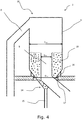
- FIG. 4 shows a magnified view of the top separator according to the invention where the central tube 9 enters the separator housing 5 through a lower part 14 of the separator housing 5 and not through the upper part 10 as opposed to the prior art solution as seen in Fig. 1 . It is essential that the central tube 9 does not enter the separator housing 5 through the upper part 10 in order to achieve the invention.
- the invention has several advantages over the prior art, the main advantage being the lowered worst-case scenario degree of filling of the top separator 2 which allows a decrease in the costs of constructing the civil building. Since the raw meal would be able to escape the separator through the central tube 9 if the outlet 15 is clogged, the weight of the completely filled top separator 2 would be much lower in a preheater according to the invention.
- the ratio between an upper part diameter D CYL of the substantially cylindrical upper part 10 of the separator housing 5 and a top separator central tube diameter Dct is between 1.8 ⁇ D CYL / D CT ⁇ 3 or more preferably 2.1 ⁇ D CYL / D CT ⁇ 2.8 or even more preferably 2.3 ⁇ D CYL / D CT ⁇ 2.6.
- the relation between the central tube diameter D CT and cylindrical upper part diameter D CYL makes it possible to obtain a fractional separation efficiency in a range between 91% to 95% which is the preferred range when the resulting pressure drop through the separator typically lies in a range between 5-20mBar.
- the top separator upper part diameter of the cylindrical upper part of the top separator housing is larger than a bottom separator upper part diameter of the upper part of the bottom separator housings of the bottom separators.
- a new top separator may be fitted into an existing receiving opening 17 of the suspension 16 by supporting the housing on the conical part of the housing and thereby a new separator having a larger diameter D CYL of the cylindrical part 10 in the new top separator 2 than in the old top separator 2 without changing the suspension design of the suspension 16 or the diameter D RO of the receiving opening 17.
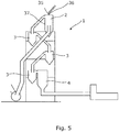
- Fig. 5 shows a cross-sectional view of a multi-stage cement calcining plant suspension preheater 1 of the invention comprising a plurality of stages each of which has a separator for separating raw cement meal from a gas in which the meal is suspended and wherein said separators of said plurality of stages are serially connected and in series with a calcining combustor 4, where the plurality of stages comprises a top separator 2 arranged at the uppermost stage of the preheater and a plurality of bottom separators 3 arranged at the lowermost stages of the preheater wherein the top separator 2 comprises a material feed inlet 35 arranged in a central part 36 of the upper part of the top separator housing 37.
- Fig. 6 shows a cross-sectional view of a multi-stage cement calcining plant suspension preheater of the prior art also comprising a plurality of stages each of which has a separator for separating raw cement meal from a gas in which the meal is suspended and wherein said separators of said plurality of stages are serially connected and in series with a calcining combustor 4, where the plurality of stages comprises a top separator 2 arranged at the uppermost stage of the preheater and a plurality of bottom separators 3 arranged at the lowermost stages of the preheater.
- the number of cyclones has been reduced from five to four and furthermore the position of the material feed inlet 35 has been re-arranged from the tubing between the uppermost and second uppermost separator in the prior art of Fig. 6 to a material feed inlet 35 directly introducing the material in the top separator in a central position of the upper part of the housing of the top separator 2.
- the introduction of the material directly into the central part of the top separator forces the material to pass the airstream in counter-current and not as in the prior art co-current with the airstream.
- the heat exchange obtained by introduction of the material counter-current is so much better, that an entire cyclone stage may be removed enabling a lower preheater structure with the same capacity or a higher capacity at the same height.
- Fig. 7a shows a cross-sectional view of a multi-stage cement calcining plant suspension preheater of the invention wherein the material feed inlet 35 comprises means for spreading the material feed 38 in a tangential and or radial direction.
- Fig. 7b shows a magnified view of an embodiment of a material feed inlet comprising means for spreading the material feed 38 in a tangential and or radial direction in a tangential direction.
- Fig. 8 shows a cross-sectional view of the same embodiment as in Fig. 7b , where the material feed inlet 35 comprises means for spreading the material feed 38 having a rotation axle 39 driven by a motor 40 and a material feed duct 41 for spilling the material feed onto a rotating plate 12 with shovel blades 43.
- Figs. 9a-d show four different embodiments of a rotating plate 12 with shovel blades 43 driven by a rotation axle.
- Fig. 10a shows a cross-sectional view of a top cyclone of the invention with airflow and material flow patterns.
- the top separator 44 comprises a tangential inlet 22 in the upper part of the separator housing, a top separator central tube 15 entering the separator housing 46 in the lower part 17 of the top separator housing 46, and wherein the top separator 44 comprises a material feed inlet 35 arranged in a central part 48 of an upper part 19 of the top separator housing 46.
- the material exits the top separator 44 through an outlet in a lowermost end 21 of the conical lower part 20.
- the airflow enters the cyclone in the periphery of the upper part 19 of the top separator and exits the cyclone through the central tube extending with a free end axially into the separator housing in the substantially conical lower part 20 of the top separator, whereas the flow pattern of the material feed according to the invention enters the top separator from the centrally arranged material feed inlet 35 and is directed towards the periphery of the separator by centrifugal forces. Therefore the air and material is mixed in counter-current flow increasing the heat exchange significantly.
- the material feed inlet 35 may comprise means for spreading the material feed 38 in a tangential and/or radial direction of the separator housing 46 of the top separator 14 directing the material feed in a direction from the centrally arranged inlet towards the periphery of the housing of the top separator 14.
- the means for spreading the material feed 38 in Fig. 10a comprises two tubes 23 connected to a material feed container 24 and further connected to a valve 49 for allowing pressurized air to enter the tubes 23 and speed up the material entering the top separator 14.
- the means for spreading the material feed 38 comprises a rotation axle 39 driven and a material feed duct 41 for spilling the material feed onto a rotating plate 12 with shovel blades 13 shows a cross-sectional view of a top cyclone of the invention with airflow and material flow patterns. As illustrated also in Fig.
- the airflow enters the cyclone in the periphery of the upper part 19 of the top separator and exits the cyclone through the central tube extending with a free end axially into the separator housing in the substantially conical lower part 20 of the top separator, whereas the flow pattern of the material feed according to the invention enters the top separator from the centrally arranged material feed inlet 35 and is directed towards the periphery of the separator by centrifugal forces. Therefore the air and material is mixed in counter-current flow increasing the heat exchange significantly.
- the material feed inlet 35 may comprise means for spreading the material feed 38 in a tangential and/or radial direction of the separator housing 46 of the top separator 14 directing the material feed in a direction from the centrally arranged inlet towards the periphery of the housing of the top separator 14.
- Figs. 11a-c show three different arrangements of means for spreading the material feed 38 in a separator.
- Fig. 11a shows the means for spreading the material feed 38 arranged partially outside a central part 26 of the separator housing 46. This is unwanted since it will create an inhomogeneous distribution of material in the separator.
- the means for spreading the material feed 38 must be arranged in a central part of the separator housing to provide a homogeneous distribution of the material in the separator housing the material feed inlet is to be placed in a central part.
- an inlet zone 27 between the means for spreading the material feed 38 and the tangential inlet 22 may comprise an inlet shield 28. Placing an inlet shield 28 in the inlet zone 27 is more advantageous than arranging the means for spreading the material feed 38 away from the central part 26 of the separator housing 46. As shown in Fig. 11c the means for spreading the material feed 38 is optimally placed in the central part of the cylindrical part of the separator housing 46.
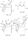
- Fig. 12a shows a perspective view of an embodiment of the means for spreading the material feed 38 in a cyclone comprising two tubes entering the separator housing 46 in the central part of the upper part.
- Fig. 12b shows a cross-sectional view of an embodiment of the means for spreading the material feed 38 in a cyclone comprising two tubes entering the separator housing 46 in the central part of the upper part.
- Fig. 12c shows a perspective view of an embodiment of the means for spreading the material feed in a cyclone comprising three tubes entering the separator housing 46 in the central part of the upper part.
- Fig. 12a shows a perspective view of an embodiment of the means for spreading the material feed 38 in a cyclone comprising two tubes entering the separator housing 46 in the central part of the upper part.
- FIG. 12d shows a perspective view of an embodiment of a top cyclone comprising means for spreading the material feed 38 comprising two tubes 23 and means for accelerating the material feed by introducing pressurised air through a valve 49 to accelerate material conveyed from a material feed container 24.
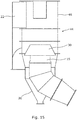
- Fig. 13 shows a cross-sectional view of a top cyclone of the invention with airflow and material flow patterns.
- the top separator comprises a tangential inlet 22 in the upper part of the separator housing, a top separator central tube 45 entering the separator housing 46 in the lower part 47 of the top separator housing 46, and wherein the top separator comprises a material feed inlet 35 arranged in a central part 18 of an upper part 19 of the top separator housing 46. The material exits the top separator through an outlet in a lowermost end 21 of the conical lower part 20.
- the airflow enters the cyclone in the periphery of the upper part 19 of the top separator and exits the cyclone through the central tube extending with a free end axially into the separator housing in the substantially conical lower part 20 of the top separator, whereas the flow pattern of the material feed according to the invention enters the top separator from the centrally arranged material feed inlet 35 and is directed towards the periphery of the separator by centrifugal forces. Therefore the air and material is mixed in counter-current flow increasing the heat exchange significantly.
- the material feed inlet 35 may comprise means for spreading the material feed 38 in a tangential and/or radial direction of the separator housing 46 of the top separator directing the material feed in a direction from the centrally arranged inlet towards the periphery of the housing of the top separator.
- the means for spreading the material feed 38 in Fig. 13 comprises two tubes 23 connected to a material feed container 24 and further connected to a valve 49 for allowing pressurized air to enter the tubes 23 and speed up the material entering the top separator.
- Fig. 14a shows a perspective view of an embodiment of a means for spreading the material feed comprising two tubes 23 angled in a radial and tangential direction for introducing the material feed in the cyclone with a radial and tangential velocity component.
- Fig. 14b shows a perspective view of an embodiment of a means for spreading the material feed 38 comprising one tube 23 and a splash plate 29 angled in a radial and tangential direction for introducing the material feed in the cyclone with a radial and tangential velocity component.
- Fig. 15 shows a cross-sectional perspective view of a top cycle with flow restriction means 30 on the top separator central tube 45 of a top separator 44.
Description
- The present invention relates to a multi-stage cement calcining plant suspension preheater for preheating the cement raw meal prior to its being burned in a kiln into cement clinker which is subsequently cooled in a clinker cooler. The preheater comprises a top separator comprising a central tube entering the top separator in a lowermost part of the separator housing whereas the central tubes of the bottom separators enters the separator housing in an upper part of the separator housing. Also the invention relates to a method of installing a top separator of the aforementioned kind. Also the invention relates to a top separator comprising a material feed inlet arranged in a central part of the upper part of the top separator housing.
- In the cement industry it is customary practice to use a so-called cyclone preheater for preheating the cement raw meal prior to its being burned in a kiln into cement clinker which is subsequently cooled in a clinker cooler. Typically, a cyclone preheater comprising four to six cyclone stages is used arranged in a preheater tower construction. The raw meal is introduced in the first cyclone stage and heated by direct contact with hot exhaust gases from the kiln according to the counter flow principle. Preheaters of this kind are generally known from the patent literature and one example is provided in
EP 0 455 301 - A well-known limitation of the capacity of such pre-heater towers is the building costs of such towers easily exceeding 100 meters nowadays. Consequently civil construction costs are very high for these preheater towers. One aspect especially makes the construction costs very high for these towers namely that they are dimensioned after the weight of the all cyclones including the material present in the cyclones. During operation the weight of material in the separator cyclone stages are not very high, since the raw meal is suspended in an air stream. However, if the outlet of the cyclones for some reason clog up the cyclones will gradually fill up the entire inner space of the cyclones until the inlet of the cyclone is also clogged. A cyclone stage completely filled with compacted raw mill adds several tons to the empty weight of the cyclone and thereby to the preheater tower construction. When dimensioning a preheater tower, the construction must typically be dimensioned according to worst case scenarios. Typically the maximum filling level of the cyclones is a critical parameter. All preheater towers are dimensioned to accommodate even critical situations when filling levels become close to the worst-case scenario e.g. due to clogging.
- Therefore it would be advantageous to be able to construct a preheater tower and preheater system with the ability to minimize the worst case scenario weight of the cyclones filled to their maximum filling level such that capacity may be increased without burdening the construction costs severely in these tall constructions.
- Another aspect also that makes it necessary to build these very high towers is the need for high production rates with high temperature differences. Maintaining high production rates at high temperature differences require optimal heat exchange between air and raw meal material.
- Therefore it would also be advantageous to be able to construct a preheater tower and preheater system with the ability to improve heat exchange compared to the prior art to decrease height of these towers or maximize production rates at the same height or even allow for less preheater stages to be used by using less separators in the towers.
-
BE698006A US5131462A discloses a heat exchanger in the form of a vessel for heat exchange of a pulverulent solid material and a gas, e.g. for preheating raw materials prior to a burning process by use of the hot exit gases fed to the vessel; consists of a hollow cylindrical central part with a tangential gas inlet, a conical base with a material outlet, and a downwardly orientated gas out, a concave upper part facing the central part and with at least one material inlet. The downwardly orientated gas outlet is mounted initially axially as a central pipe inside the vessel and is provided with a skirt; the height of the upper part, the distance of the material inlet from the vertical axis of the heat exchanger and the inclination of the inlet to the horizontal plane, the height of the central pipe gas inlet above the lower end level of the central part of the vessel and the inclination of the skirt are all dimensioned so as to provide optimum conditions, partly for heat exchange in radial counter current between material and gas, partly for separation of material from gas inside the vessel due to the downwardly orientated axial and tangential gas velocities. -
JPS60161762A -
US4997363 is a further example of a multi-stage cement calcining plant suspension preheater known in the technical field. - It is an object of the present invention to wholly or partly overcome the above disadvantages and drawbacks of the prior art. More specifically, it is an object to provide an improved multi-stage cement calcining plant suspension preheater of the kind mentioned in the introduction, wherein the preheater comprises a top separator comprising a central tube entering the top separator in a lowermost part of the separator housing whereas the central tubes of the bottom separators enters the separator housing in an upper part of the separator housing. Also it is an object of the present invention to provide a method comprising the steps of removing an old uppermost separator having a first housing diameter in an existing multi-stage cement calcining plant and installing a new uppermost separator having a second housing diameter being larger than the first housing diameter of the old uppermost separator.
- Another object of the present invention is to provide an improved multi-stage cement calcining plant suspension preheater of the kind mentioned in the introduction, wherein the preheater comprises a top separator comprising a central tube entering the top separator in a lowermost part of the separator housing whereas the central tubes of the bottom separators enters the separator housing in an upper part of the separator housing, and wherein the top separator comprises a material feed inlet arranged in a central part of the upper part of the top separator housing.
- The above objects, together with numerous other objects, advantages, and features, which will become evident from the below description, are accomplished by a solution in accordance with the present invention by a preheater comprises a plurality of stages each of which has a separator for separating raw cement meal from a gas in which the meal is suspended and wherein the separators of said plurality of stages are serially connected and in series with a calcining combustor. Further the plurality of stages comprises a top separator arranged at the uppermost stage of the preheater and a plurality of bottom separators arranged at the lowermost stages of the preheater, where the separators comprise a separator housing comprising a substantially cylindrical upper part and a substantially conical lower part, a tangential inlet in the upper part of the separator housing for introducing an un-separated stream of gas and raw cement meal in suspension, an outlet in a lowermost end of the conical part for discharging a first fraction of coarse cement raw meal material, a central tube extending with a free end axially into the separator housing for diverting a second fraction of fine cement raw meal material and gas, and where the central tube of the top separator enters the separator housing in the lower part of the separator housing, whereas the central tubes of the bottom separators enters the separator housing in the upper part of the separator housing, and further wherein the top separator comprises a top separator suspension having a receiving opening for receiving and supporting the top separator and wherein a receiving opening diameter of the receiving opening is smaller than a top separator upper part diameter of the upper part of the top separator housing and wherein the top separator is suspended by the top separator suspension engaging the lower part of the top separator housing.
- In one embodiment of the invention, a ratio between an upper part diameter DCYL of the substantially cylindrical upper part of the separator housing and a top separator central tube diameter Dct is between 1.8< DCYL/ DCT<3 or more preferably 2.1 < DCYL/ DCT <2.8 or even more preferably 2.3< DCYL/ DCT <2.6.
- With these parameters of the central tube diameter DCT and cylindrical upper part diameter DCYL it is possible to obtain a fractional separation efficiency in a range between 91% to 95% which is the preferred range. The resulting pressure drop through the separator typically lies in a range between 5-20mBar.
- In another embodiment of the invention, the top separator upper part diameter of the upper part of the top separator housing is larger than a bottom separator upper part diameter of the upper part of the bottom separator housings of the bottom separators.
- In a method of constructing a multi-stage cement calcining plant suspension preheater according to the invention an old uppermost top separator having a first housing diameter is removed from an existing multi-stage cement calcining plant and a new uppermost separator having a second housing diameter being larger than the first housing diameter of the old uppermost separator is arranged in a support frame of the old uppermost separator.
- The above objects, together with numerous other objects, advantages, and features, which will become evident from the below description, are also accomplished by a solution in accordance with the present invention by a preheater comprising a plurality of stages each of which has a separator for separating raw cement meal from a gas in which the meal is suspended and wherein said separators of said plurality of stages are serially connected and in series with a calcining combustor, and where said plurality of stages comprise a top separator arranged at the uppermost stage of the preheater and a plurality of bottom separators arranged at the lowermost stages of the preheater, furthermore the bottom separators comprise a separator housing comprising a substantially cylindrical upper part and a substantially conical lower part, a tangential inlet in the upper part of the separator housing for introducing an unseparated stream of gas and raw cement meal in suspension, an outlet in a lowermost end of the conical part for discharging a first fraction of coarse cement raw meal material, a central tube extending with a free end axially into the separator housing for diverting a second fraction of fine cement raw meal material and gas, a top separator central tube of the top separator entering the separator housing in the lower part of the top separator housing, and a plurality of bottom separator central tubes of the bottom separators entering the bottom separator housings in the upper part of the separator housing, and further wherein the top separator comprises a material feed inlet arranged in a central part of the upper part of the top separator housing.
- In one embodiment of the invention, the preheater comprises a second top separator arranged at the second uppermost stage of the preheater comprising a top separator central tube of the second top separator entering the separator housing in the lower part of the top separator housing.
- In order to increase the capacity of the preheater the second uppermost stage may also be configured as a top separator to benefit from the centrally arranged material feed inlet.
- In another embodiment of the invention, the preheater comprises one or more additional top separators comprising top separator central tubes entering the separator housings in the lower part of the top separator housing in one or more of the lowermost stages.
In certain configurations of the preheater a second stage of the preheater may also benefit from having a centrally arranged material feed inlet. A top cyclone and a second cyclone with centrally arranged material feed inlets may reduce the number of cyclones from e.g. 5 to 3 or even by introducing more cyclones with centrally arranged material feed inlets in very large preheater configurations reduce the number of cyclones from e.g. 8 to 5 while still maintaining the same production rate as the eight-cyclone configuration using prior art cyclone designs. - In another embodiment of the invention, the material feed inlet arranged in the central part of the upper part of the one or more top separators are arranged co-axially with a longitudinal centre axis of the housing of the one or more top separators.
- By arranging the material feed inlet in the central part of the upper part of the one or more top separators co-axially with a longitudinal centre axis of the housing, the material inlet may provide several benefits to the system. The central position ensures the crossflow path of the material from the central position towards the periphery crossing the air path from the periphery towards the centrally arranged outlet, but further the arrangement of the inlet co-axially with the longitudinal axis of the housing allows the inlet to function as a vortex finder ensuring the best possible vortex flow conditions in the cyclone.
- In another embodiment of the invention, at least the material feed inlet of one or more of the top separators comprises means for spreading the material feed in a tangential direction of the housing of the top separator directing the material feed in a direction from the centrally arranged inlet towards the periphery of the housing of the top separator such that the material exiting the material inlet has a tangential velocity component in a tangential direction of the top separator housing.
- In this embodiment the material inlet of one or more of the top separators has been provided with means for actively spreading the material upon entry in the cyclone. Since the air stream in the cyclones is rotating around the longitudinal axis the air stream itself will upon mixing with the material transport the material towards the periphery from the centrally arranged inlet due to centrifugal forces. However, to increase the tangential velocity of the material entering the cyclone in the tangential direction from the inlet means for spreading the material feed in a tangential direction of the housing of the top separator from the centrally arranged inlet towards the periphery in the tangential direction is advantageously introduced to maximize the crossflow heat exchange.
- In another embodiment of the invention, the means for spreading the material feed in a tangential direction of the housing of the top separator directing the material feed in a direction from the centrally arranged inlet towards the periphery of the housing of the top separator such that the material exiting the material inlet has a tangential velocity component in a tangential direction of the top separator housing, wherein the tangential direction is co-current with the direction of airflow in the top separator.
- In another embodiment of the invention, at least the material feed inlet of one or more of the top separators comprises means for spreading the material feed in a radial direction of the housing of the top separator directing the material feed in a direction from the centrally arranged inlet towards the periphery of the housing of the top separator such that the material exiting the material inlet has a radial velocity component in a radial direction of the top separator housing.
- Also increasing the velocity of the material feed but further in the radial direction means for spreading the material feed in a radial direction may also be introduced to increase the radial velocity component of the material feed to achieve a velocity of the material feed optimized to compliment the airstream of the cyclone to have the best possible cross-flow heat exchange properties.
- In another embodiment of the invention, the means for spreading the material feed in a radial and/or tangential direction comprises an exit tube directed in a radial and/or tangential direction.
- A cheap solution with low maintenance of the means for spreading the material feed in a radial and/or tangential direction is directing the material feed through a tube in a specific or adjustable direction to ensure the exiting material has a certain tangential and/or radial velocity component.
- In another embodiment of the invention, the means for spreading the material feed in a radial and/or tangential direction comprises a splash plate angled in a radial and/or tangential direction.
- To facilitate for instance an adjustable solution the material stream in the inlet may be directed through a tube and then diverged by a splash plate in the correct angle. The splash plate may be adjustable for fine tuning of the flow path of the material or for operation under various operation modes, different airstream volumes, different materials, different material size compositions etc.. The splash plate may also be advantageous to allow the means for spreading the material feed to be centrally arranged with a limited extension in the radial direction.
- In another embodiment of the invention, the means for spreading the material feed in a radial and/or tangential direction comprises material accelerating means such as pressurized air or mechanical conveyor means.
- The speed of the material particles may be further increased by adding pressurized air to the stream of material entering through the inlet or by accelerating the material stream by other means of conveying to ensure that the speed of the material complements the airstream properties to maximize heat exchange.
- In another embodiment of the invention, the means for spreading the material feed in a radial and/or tangential direction comprises a rotating plate for accelerating the material after entry into the separator.
- It may be advantageous to avoid additional airstreams entering the cyclones with cold or preheated air, since false air is typically lowering efficiency of the cyclone and an embodiment of the means for spreading the material inside the cyclone not necessitating pressurized air or other external means for accelerating the material is to introduce a rotating plate inside cyclone at the material inlet and then spill the material feed on the rotating plate and control the radial and tangential velocity components by the rotational speed of the rotating plate. The rotating plate is advantageously arranged inside the cyclone on a rotation axle entering the cyclone in the longitudinal direction.
- In another embodiment of the invention, the rotating plate of the means for spreading the material feed comprises one or more substantially vertical shovel blades for forcing the material in the direction of rotation of the rotating plate.
- To improve the gripping effect of the material on the rotating plate, the rotating plate preferably comprises one or more shovel blades. The shovel blades allow the material stream to be more quickly accelerated by ensuring that the material stream archives the same rotational speed as the rotating plate. Most advantageously, the shovel blades allows the rotating plate to significantly increase the tangential component of the material feed since the shovel blade will force the material in the tangential direction when exiting the rotating plate.
- In another embodiment of the invention, the shovel blades of the rotating plate extend from the centre of the rotating plate to the periphery of the rotating plate in a substantial radial direction.
- The most optimal direction of the shovel blades is in the radial direction where the material feed receives a primarily tangential accelerating force from the shovel blades at the exit point where the material feed exits the rotating plate.
- In another embodiment of the invention, the shovel blades of the rotating plate are gradually decreasing in height from the centre of the rotating plate towards the periphery of the rotating plate.
- When using rotation plates the material feed is typically done centrally around the rotation axle of the rotating plate. Therefore it may be advantageous to increase the height of the shovel blades at least near the centre to begin accelerating the material stream as soon as possible in its way towards the rotating plate, however, to still have a rotating plate of the lowest possible weight and dimension the height is optimally decreasing in height towards the periphery since the material stream near the periphery will be following the rotating plate rather than still be flowing freely downwards through the air.
- The invention and its many advantages will be described in more detail below with reference to the accompanying schematic drawings, which for the purpose of illustration show some non-limiting embodiments and in which
-
Fig. 1 shows a cross-sectional view of a multi-stage cement calcining plant suspension preheater of the prior art; -
Fig. 2 shows a cross-sectional view of a multi-stage cement calcining plant suspension preheater of the invention; -
Fig. 3 shows a magnified view of a top separator of a multi-stage cement calcining plant suspension preheater of the prior art; -
Fig. 4 shows a magnified view of a top separator of a multi-stage cement calcining plant suspension preheater of the invention. -
Fig. 5 shows a cross-sectional view of a multi-stage cement calcining plant suspension preheater of the invention; -
Fig. 6 shows a cross-sectional view of a multi-stage cement calcining plant suspension preheater of the prior art; -
Fig. 7a shows a cross-sectional view of a multi-stage cement calcining plant suspension preheater of the invention; -
Fig. 7b shows a magnified view of an embodiment of a material feed inlet of a top separator of a multi-stage cement calcining plant suspension preheater of the invention; -
Fig. 8 shows a cross-sectional view of an embodiment of a material feed inlet of a top separator of a multi-stage cement calcining plant suspension preheater of the invention; -
Figs. 9a-d show four different embodiments of a rotating plate of the invention; -
Fig. 10a shows a cross-sectional view of a top cyclone of the invention with airflow and material flow patterns; -
Fig. 10b shows a cross-sectional view of a top cyclone of the invention with airflow and material flow patterns; -
Figs. 11a-c show four different arrangements of means for spreading the material feed in a cyclone; -
Fig. 12a shows a perspective view of an embodiment of the means for spreading the material feed in a cyclone comprising two tubes; -
Fig. 12b shows a cross-sectional view of an embodiment of the means for spreading the material feed in a cyclone comprising two tubes; -
Fig. 12c shows a perspective view of an embodiment of the means for spreading the material feed in a cyclone comprising three tubes; -
Fig. 12d shows a perspective view of an embodiment of a top cyclone comprising means for spreading the material feed comprising two tubes and means for accelerating the material feed by introducing pressurised air through a valve; -
Fig. 13 shows a cross-sectional perspective view with flow patterns of an embodiment of a top cyclone comprising the means for spreading the material feed comprising two tubes and means for accelerating the material feed by introducing pressurised air through a valve; -
Fig. 14a shows a perspective view of an embodiment of a means for spreading the material feed comprising two tubes angled in a radial and tangential direction for introducing the material feed in the cyclone with a radial and tangential velocity component; -
Fig. 14b shows a perspective view of an embodiment of a means for spreading the material feed comprising one tube and a splash plate angled in a radial and tangential direction for introducing the material feed in the cyclone with a radial and tangential velocity component; and -
Fig. 15 shows a cross-sectional perspective view of a top cycle with flow restriction means on the outlet of a top cyclone. - All the figures are highly schematic and not necessarily to scale, and they show only those parts which are necessary in order to elucidate the invention, other parts being omitted or merely suggested.
-
Fig. 1 shows a cross-sectional view of a multi-stage cement calciningplant suspension preheater 1 of the prior art comprising a plurality of stages each of which has a separator for separating raw cement meal from a gas in which the meal is suspended and wherein said separators of said plurality of stages are serially connected and in series with acalcining combustor 4, where the plurality of stages comprises atop separator 2 arranged at the uppermost stage of the preheater and a plurality ofbottom separators 3 arranged at the lowermost stages of the preheater.Fig. 2 shows a cross-sectional view of a multi-stage cement calcining plant suspension preheater of the invention also comprising a plurality of stages each of which has a separator for separating raw cement meal from a gas in which the meal is suspended and wherein said separators of said plurality of stages are serially connected and in series with acalcining combustor 4, where the plurality of stages comprises atop separator 2 arranged at the uppermost stage of the preheater and a plurality ofbottom separators 3 arranged at the lowermost stages of the preheater. As becomes evident from the difference between the prior art preheater shown inFig. 1 and the preheater of the invention shown inFig. 2 , the height H1 of thetubing 13 leading to thetop separator 2 of the prior art is much higher than the height H2 of thetubing 13 leading to thetop separator 2 of the invention and thus construction costs are significantly limited.Fig. 3 is a magnified view of the top separator of the preheater of the prior art as shown inFig. 1 . As seen inFig. 3 the top separator of the preheater of the prior art comprises acentral tube 9 of the top separator which enters the separator housing in theupper part 10 of theseparator housing 5, like the central tubes of the bottom separators enters the separator housing in the upper part of the separator housing as shown inFig. 1 . Theseparators separator housing 5 comprising a substantially cylindricalupper part 6 and a substantially conicallower part 7, atangential inlet 8 in anupper part 10 of theseparator housing 5 for introducing an un-separated stream of gas and raw cement meal in suspension. Further the top separator of the prior art comprises anoutlet 15 in alowermost end 44 of theconical part 7 for discharging a first fraction of coarse cement raw meal material, and acentral tube 9 extending with a free end axially into theseparator housing 5 for diverting a second fraction of fine cement raw meal material and gas. Thecentral tube 9 of thetop separator 2 enters the separator housing in theupper part 10 of theseparator housing 5. Furthermore, thetop separator 2 comprises atop separator suspension 16 having a receivingopening 17 for receiving and supporting thetop separator 2. As seen by the hatched area the top separator of the prior art has a worst-case scenario filling 18 extending up till thetangential inlet 8. If theoutlet 15 is clogged during operation the top separator may be filled until the raw meal finally can escape the separator through thecentral tube 9. The weight of a completely filled separator with this degree of filling is very substantial and the civil construction must be dimensioned to be able to accommodate this weight.Fig. 4 shows a magnified view of the top separator according to the invention where thecentral tube 9 enters theseparator housing 5 through alower part 14 of theseparator housing 5 and not through theupper part 10 as opposed to the prior art solution as seen inFig. 1 . It is essential that thecentral tube 9 does not enter theseparator housing 5 through theupper part 10 in order to achieve the invention. The invention has several advantages over the prior art, the main advantage being the lowered worst-case scenario degree of filling of thetop separator 2 which allows a decrease in the costs of constructing the civil building. Since the raw meal would be able to escape the separator through thecentral tube 9 if theoutlet 15 is clogged, the weight of the completely filledtop separator 2 would be much lower in a preheater according to the invention. Furthermore this has the advantage that old top separators could be interchanged in existing preheaters with larger top separators without enforcing the civil construction further. The construction has been dimensioned according to the old type of top separators and the new type will have a lower worst-case scenario filling weight, thus it is possible to install a larger separator using the existing construction. As seen inFig. 4 even the existing suspension of the old top separator may be re-used since the new top separator having a larger diameter Dcyl of thecylindrical part 10 may be supported in the existingsuspension 16, since the separator may be supported on the conical part of the separator. - Preferably the ratio between an upper part diameter DCYL of the substantially cylindrical
upper part 10 of theseparator housing 5 and a top separator central tube diameter Dct is between 1.8< DCYL/ DCT<3 or more preferably 2.1< DCYL/ DCT <2.8 or even more preferably 2.3< DCYL/ DCT <2.6. - The relation between the central tube diameter DCT and cylindrical upper part diameter DCYL makes it possible to obtain a fractional separation efficiency in a range between 91% to 95% which is the preferred range when the resulting pressure drop through the separator typically lies in a range between 5-20mBar. The top separator upper part diameter of the cylindrical upper part of the top separator housing is larger than a bottom separator upper part diameter of the upper part of the bottom separator housings of the bottom separators.
- As seen in
Fig. 4 a new top separator may be fitted into an existing receivingopening 17 of thesuspension 16 by supporting the housing on the conical part of the housing and thereby a new separator having a larger diameter DCYL of thecylindrical part 10 in the newtop separator 2 than in the oldtop separator 2 without changing the suspension design of thesuspension 16 or the diameter DRO of the receivingopening 17. -
Fig. 5 shows a cross-sectional view of a multi-stage cement calciningplant suspension preheater 1 of the invention comprising a plurality of stages each of which has a separator for separating raw cement meal from a gas in which the meal is suspended and wherein said separators of said plurality of stages are serially connected and in series with acalcining combustor 4, where the plurality of stages comprises atop separator 2 arranged at the uppermost stage of the preheater and a plurality ofbottom separators 3 arranged at the lowermost stages of the preheater wherein thetop separator 2 comprises amaterial feed inlet 35 arranged in acentral part 36 of the upper part of thetop separator housing 37. -
Fig. 6 shows a cross-sectional view of a multi-stage cement calcining plant suspension preheater of the prior art also comprising a plurality of stages each of which has a separator for separating raw cement meal from a gas in which the meal is suspended and wherein said separators of said plurality of stages are serially connected and in series with acalcining combustor 4, where the plurality of stages comprises atop separator 2 arranged at the uppermost stage of the preheater and a plurality ofbottom separators 3 arranged at the lowermost stages of the preheater. As becomes evident from the difference between the present invention preheater shown inFig. 5 and the prior art preheater shown inFig. 6 , the number of cyclones has been reduced from five to four and furthermore the position of thematerial feed inlet 35 has been re-arranged from the tubing between the uppermost and second uppermost separator in the prior art ofFig. 6 to amaterial feed inlet 35 directly introducing the material in the top separator in a central position of the upper part of the housing of thetop separator 2. The introduction of the material directly into the central part of the top separator forces the material to pass the airstream in counter-current and not as in the prior art co-current with the airstream. The heat exchange obtained by introduction of the material counter-current is so much better, that an entire cyclone stage may be removed enabling a lower preheater structure with the same capacity or a higher capacity at the same height. -
Fig. 7a shows a cross-sectional view of a multi-stage cement calcining plant suspension preheater of the invention wherein thematerial feed inlet 35 comprises means for spreading thematerial feed 38 in a tangential and or radial direction.Fig. 7b shows a magnified view of an embodiment of a material feed inlet comprising means for spreading thematerial feed 38 in a tangential and or radial direction in a tangential direction. -
Fig. 8 shows a cross-sectional view of the same embodiment as inFig. 7b , where thematerial feed inlet 35 comprises means for spreading thematerial feed 38 having arotation axle 39 driven by amotor 40 and amaterial feed duct 41 for spilling the material feed onto arotating plate 12 withshovel blades 43. -
Figs. 9a-d show four different embodiments of arotating plate 12 withshovel blades 43 driven by a rotation axle. -
Fig. 10a shows a cross-sectional view of a top cyclone of the invention with airflow and material flow patterns. As shown inFig. 10a thetop separator 44 comprises atangential inlet 22 in the upper part of the separator housing, a top separatorcentral tube 15 entering theseparator housing 46 in thelower part 17 of thetop separator housing 46, and wherein thetop separator 44 comprises amaterial feed inlet 35 arranged in acentral part 48 of anupper part 19 of thetop separator housing 46. The material exits thetop separator 44 through an outlet in alowermost end 21 of the conicallower part 20. As illustrated the airflow enters the cyclone in the periphery of theupper part 19 of the top separator and exits the cyclone through the central tube extending with a free end axially into the separator housing in the substantially conicallower part 20 of the top separator, whereas the flow pattern of the material feed according to the invention enters the top separator from the centrally arrangedmaterial feed inlet 35 and is directed towards the periphery of the separator by centrifugal forces. Therefore the air and material is mixed in counter-current flow increasing the heat exchange significantly. To adjust the speed and direction of the material feed thematerial feed inlet 35 may comprise means for spreading thematerial feed 38 in a tangential and/or radial direction of theseparator housing 46 of thetop separator 14 directing the material feed in a direction from the centrally arranged inlet towards the periphery of the housing of thetop separator 14. The means for spreading thematerial feed 38 inFig. 10a comprises twotubes 23 connected to amaterial feed container 24 and further connected to avalve 49 for allowing pressurized air to enter thetubes 23 and speed up the material entering thetop separator 14. - In
Fig. 10b the means for spreading thematerial feed 38 comprises arotation axle 39 driven and amaterial feed duct 41 for spilling the material feed onto arotating plate 12 withshovel blades 13 shows a cross-sectional view of a top cyclone of the invention with airflow and material flow patterns. As illustrated also inFig. 10b the airflow enters the cyclone in the periphery of theupper part 19 of the top separator and exits the cyclone through the central tube extending with a free end axially into the separator housing in the substantially conicallower part 20 of the top separator, whereas the flow pattern of the material feed according to the invention enters the top separator from the centrally arrangedmaterial feed inlet 35 and is directed towards the periphery of the separator by centrifugal forces. Therefore the air and material is mixed in counter-current flow increasing the heat exchange significantly. To adjust the speed and direction of the material feed thematerial feed inlet 35 may comprise means for spreading thematerial feed 38 in a tangential and/or radial direction of theseparator housing 46 of thetop separator 14 directing the material feed in a direction from the centrally arranged inlet towards the periphery of the housing of thetop separator 14. -
Figs. 11a-c show three different arrangements of means for spreading thematerial feed 38 in a separator.Fig. 11a shows the means for spreading thematerial feed 38 arranged partially outside acentral part 26 of theseparator housing 46. This is unwanted since it will create an inhomogeneous distribution of material in the separator. As shown inFig. 11b , the means for spreading thematerial feed 38 must be arranged in a central part of the separator housing to provide a homogeneous distribution of the material in the separator housing the material feed inlet is to be placed in a central part. If the airstream entering theseparator housing 46 through thetangential inlet 22 forces the material towards the periphery of theseparator housing 46 too quickly to provide optimal heat exchange, aninlet zone 27 between the means for spreading thematerial feed 38 and thetangential inlet 22 may comprise aninlet shield 28. Placing aninlet shield 28 in theinlet zone 27 is more advantageous than arranging the means for spreading thematerial feed 38 away from thecentral part 26 of theseparator housing 46. As shown inFig. 11c the means for spreading thematerial feed 38 is optimally placed in the central part of the cylindrical part of theseparator housing 46. -
Fig. 12a shows a perspective view of an embodiment of the means for spreading thematerial feed 38 in a cyclone comprising two tubes entering theseparator housing 46 in the central part of the upper part.Fig. 12b shows a cross-sectional view of an embodiment of the means for spreading thematerial feed 38 in a cyclone comprising two tubes entering theseparator housing 46 in the central part of the upper part.Fig. 12c shows a perspective view of an embodiment of the means for spreading the material feed in a cyclone comprising three tubes entering theseparator housing 46 in the central part of the upper part.Fig. 12d shows a perspective view of an embodiment of a top cyclone comprising means for spreading thematerial feed 38 comprising twotubes 23 and means for accelerating the material feed by introducing pressurised air through avalve 49 to accelerate material conveyed from amaterial feed container 24. -
Fig. 13 shows a cross-sectional view of a top cyclone of the invention with airflow and material flow patterns. As shown inFig. 13 the top separator comprises atangential inlet 22 in the upper part of the separator housing, a top separator central tube 45 entering theseparator housing 46 in thelower part 47 of thetop separator housing 46, and wherein the top separator comprises amaterial feed inlet 35 arranged in acentral part 18 of anupper part 19 of thetop separator housing 46. The material exits the top separator through an outlet in alowermost end 21 of the conicallower part 20. - As illustrated the airflow enters the cyclone in the periphery of the
upper part 19 of the top separator and exits the cyclone through the central tube extending with a free end axially into the separator housing in the substantially conicallower part 20 of the top separator, whereas the flow pattern of the material feed according to the invention enters the top separator from the centrally arrangedmaterial feed inlet 35 and is directed towards the periphery of the separator by centrifugal forces. Therefore the air and material is mixed in counter-current flow increasing the heat exchange significantly. To adjust the speed and direction of the material feed thematerial feed inlet 35 may comprise means for spreading thematerial feed 38 in a tangential and/or radial direction of theseparator housing 46 of the top separator directing the material feed in a direction from the centrally arranged inlet towards the periphery of the housing of the top separator. The means for spreading thematerial feed 38 inFig. 13 comprises twotubes 23 connected to amaterial feed container 24 and further connected to avalve 49 for allowing pressurized air to enter thetubes 23 and speed up the material entering the top separator. -
Fig. 14a shows a perspective view of an embodiment of a means for spreading the material feed comprising twotubes 23 angled in a radial and tangential direction for introducing the material feed in the cyclone with a radial and tangential velocity component.Fig. 14b shows a perspective view of an embodiment of a means for spreading thematerial feed 38 comprising onetube 23 and asplash plate 29 angled in a radial and tangential direction for introducing the material feed in the cyclone with a radial and tangential velocity component. -
Fig. 15 shows a cross-sectional perspective view of a top cycle with flow restriction means 30 on the top separator central tube 45 of atop separator 44.
Claims (18)
- A multi-stage cement calcining plant suspension preheater (1) comprising:- a plurality of stages each of which has a separator (2, 3) for separating raw cement meal from a gas in which the meal is suspended and wherein said separators of said plurality of stages are serially connected and in series with a calcining combustor,- said plurality of stages comprising a top separator (2) arranged at the uppermost stage of the preheater and a plurality of bottom separators (3) arranged at the lowermost stages of the preheater,- the separators (2, 3) comprising:- a separator housing (5) comprising a substantially cylindrical upper part (6) and a substantially conical lower part (7),- a tangential inlet (8) in the upper part (10) of the separator housing (5) for introducing an un-separated stream of gas and raw cement meal in suspension,- an outlet (15) in a lowermost end of the conical part (7) for discharging a first fraction of coarse cement raw meal material,- a central tube (9) extending with a free end axially into the separator housing (5) for diverting a second fraction of fine cement raw meal material and gas,- the central tube (9) of the top separator (2) enters the separator housing in the lower part of the separator housing (5), whereas the central tubes of the bottom separators (3) enters the separator housing in the upper part (10) of the separator housing (5).
- A multi-stage cement calcining plant suspension preheater according to claim 1, wherein the top separator (2) comprises a top separator suspension having a receiving opening for receiving and supporting the top separator (2) and wherein a receiving opening diameter of the receiving opening is smaller than a top separator upper part diameter of the upper part (6) of the top separator housing (5) and wherein the top separator is suspended by the top separator suspension engaging the lower part of the top separator housing.
- A multi-stage cement calcining plant suspension preheater according to claim 1 or 2, wherein a ratio between an upper part diameter Dup of the substantially cylindrical upper part (6) of the separator housing (5) and a top separator central tube diameter Dct is between 1.8< DCYL/ DCT<3 or more preferably 2.1< DCYL/ DCT <2.8 or even more preferably 2.3< DCYL/ DCT <2.6.
- A multi-stage cement calcining plant suspension preheater according to claim 3, wherein the top separator upper part diameter of the upper part (6) of the top separator housing (5) is larger than a bottom separator upper part diameter of the upper part of the bottom separator housings of the bottom separators (3).
- A multi-stage cement calcining plant suspension preheater according to claim 1, said bottom separators (3) comprising:- a separator housing (5) comprising a substantially cylindrical upper part and a substantially conical lower part,- a tangential inlet (8) in the upper part of the separator housing for introducing an unseparated stream of gas and raw cement meal in suspension,- an outlet in a lowermost end of the conical part for discharging a first fraction of coarse cement raw meal material,- a central tube (9) extending with a free end axially into the separator housing for diverting a second fraction of fine cement raw meal material and gas,- a top separator central tube of the top separator (2) entering the separator housing (5) in the lower part of the top separator housing, and a plurality of bottom separator central tubes of the bottom separators (3) entering the bottom separator housings in the upper part (6) of the separator housing,
and wherein the top separator (2) comprises a material feed inlet (35) arranged in a central part of the upper part of the top separator housing. - A preheater according to claim 5 furthermore comprising a second top separator arranged at the second uppermost stage of the preheater comprising a top separator central tube of the second top separator entering the separator housing (5) in the lower part of the top separator housing.
- A preheater according to claim 5 or 6, comprising one or more additional top separators comprising top separator central tubes entering the separator housings (5) in the lower part of the top separator housing in one or more of the lowermost stages.
- A preheater according to any of claims 5-7, wherein the material feed inlet (35) arranged in the central part of the upper part of the one or more top separators are arranged co-axially with a longitudinal centre axis of the housing of the one or more top separators.
- A preheater according to any of claims 5-8, wherein at least the material feed inlet (35) of one or more of the top separators comprises means (38) for spreading the material feed in a tangential direction of the housing of the top separator (2) directing the material feed in a direction from the centrally arranged inlet towards the periphery of the housing of the top separator such that the material exiting the material inlet has a tangential velocity component in a tangential direction of the top separator housing.
- A preheater according to claim 9, wherein the means (38) for spreading the material feed in a tangential direction of the housing of the top separator directing the material feed in a direction from the centrally arranged inlet towards the periphery of the housing of the top separator such that the material exiting the material inlet has a tangential velocity component in a tangential direction of the top separator housing, said tangential direction being co-current with the direction of airflow in the top separator.
- A preheater according to any of claims 5-10, wherein at least the material feed inlet of one or more of the top separators comprises means (38) for spreading the material feed in a radial direction of the housing of the top separator directing the material feed in a direction from the centrally arranged inlet towards the periphery of the housing of the top separator such that the material exiting the material inlet has a radial velocity component in a radial direction of the top separator housing.
- A preheater according to any of claims 9-11, wherein the means for spreading the material feed in a radial and/or tangential direction comprises an exit tube directed in a radial and/or tangential direction.
- A preheater according to any of claims 9-12, wherein the means (38) for spreading the material feed in a radial and/or tangential direction comprises a splash plate (29) angled in a radial and/or tangential direction.
- A preheater according to any of claims 9-13, wherein the means (38) for spreading the material feed in a radial and/or tangential direction comprises material accelerating means such as pressurized air or mechanical conveyor means.
- A preheater according to any of claims 9-14, wherein the means (38) for spreading the material feed in a radial and/or tangential direction comprises a rotating plate (12) for accelerating the material after entry into the separator.
- A preheater according to claim 15, wherein the rotating plate (12) comprises one or more substantially vertical shovel blades (43) for forcing the material in the direction of rotation of the rotating plate (12).
- A preheater according to claim 16, wherein the shovel blades (43) extends from the centre of the rotating plate to the periphery of the rotating plate in a substantial radial direction.
- A preheater according to any claim 15 or 16, wherein the shovel blades (43) are gradually decreasing in height from the centre of the rotating plate towards the periphery of the rotating plate (12).
Applications Claiming Priority (3)
| Application Number | Priority Date | Filing Date | Title |
|---|---|---|---|
| DKPA201570633 | 2015-10-08 | ||
| DKPA201670099 | 2016-02-24 | ||
| PCT/EP2016/073906 WO2017060369A1 (en) | 2015-10-08 | 2016-10-06 | Multi-stage cement calcining plant suspension preheater |
Publications (2)
| Publication Number | Publication Date |
|---|---|
| EP3359899A1 EP3359899A1 (en) | 2018-08-15 |
| EP3359899B1 true EP3359899B1 (en) | 2020-08-05 |
Family
ID=57083316
Family Applications (1)
| Application Number | Title | Priority Date | Filing Date |
|---|---|---|---|
| EP16777698.8A Active EP3359899B1 (en) | 2015-10-08 | 2016-10-06 | Multi-stage cement calcining plant suspension preheater |
Country Status (5)
| Country | Link |
|---|---|
| US (1) | US10598434B2 (en) |
| EP (1) | EP3359899B1 (en) |
| CN (1) | CN108139158B (en) |
| MX (1) | MX2018002279A (en) |
| WO (1) | WO2017060369A1 (en) |
Families Citing this family (3)
| Publication number | Priority date | Publication date | Assignee | Title |
|---|---|---|---|---|
| WO2019116350A1 (en) | 2017-12-15 | 2019-06-20 | Flsmidth A/S | Cement raw meal separator apparatus and method of using same |
| US11566842B2 (en) * | 2018-05-15 | 2023-01-31 | Flsmidth A/S | Emission abatement apparatus for processing of particulates and method of using same |
| DE102019112376B4 (en) * | 2019-05-13 | 2022-01-05 | Khd Humboldt Wedag Gmbh | Heat exchanger cyclone |
Citations (10)
| Publication number | Priority date | Publication date | Assignee | Title |
|---|---|---|---|---|
| US3305940A (en) | 1963-10-14 | 1967-02-28 | Isler Walter | Heat exchange between granular material and gas |
| BE698006A (en) | 1966-10-25 | 1967-10-16 | ||
| CH457731A (en) | 1967-02-02 | 1968-06-15 | Kloeckner Humboldt Deutz Ag | Device for the thermal treatment of fine-grained solid substances with the aid of gases, in particular for the preheating of cement raw meal with the aid of hot furnace exhaust gases |
| US3593929A (en) | 1968-07-05 | 1971-07-20 | Int Paper Canada | Eccentric rotary groundwood mill |
| US4326845A (en) | 1981-01-02 | 1982-04-27 | Allis-Chalmers Corporation | Suspension preheater for cement calcining plant |
| JPS60161762A (en) | 1984-01-30 | 1985-08-23 | Hitachi Ltd | Particle separation apparatus |
| US4997363A (en) * | 1989-01-18 | 1991-03-05 | F. L. Smidth & Co. A/S | Method and apparatus for producing cement clinker |
| EP0455301A2 (en) | 1990-05-04 | 1991-11-06 | F.L. Smidth & Co. A/S (reg. no. A/S 173386) | Method and apparatus for the manufacture of clinker from mineral raw materials |
| US5131462A (en) | 1988-03-08 | 1992-07-21 | F. L. Smidth & Co. A/S | Heat exchanger |
| WO2006079498A1 (en) | 2005-01-25 | 2006-08-03 | Rheinkalk Gmbh | Multi-stage heat exchanger and cyclone separator for use in such a heat exchanger |
Family Cites Families (9)
| Publication number | Priority date | Publication date | Assignee | Title |
|---|---|---|---|---|
| US2757921A (en) * | 1953-07-10 | 1956-08-07 | Smidth & Co As F L | Method for burning of materials with heat recovery |
| KR930004539B1 (en) * | 1988-02-09 | 1993-06-01 | 캐논 가부시끼가이샤 | Gas current classifying separator |
| DE69724050T8 (en) * | 1996-01-23 | 2005-09-15 | Matsushita Refrigeration Co., Higashiosaka | ELECTRICALLY DRIVEN HERMETICALLY CAPSUED COMPRESSOR |
| CN1209537A (en) * | 1997-08-22 | 1999-03-03 | 赵静山 | Technology for remaking vertical-tube preheater |
| JP3752096B2 (en) * | 1999-03-03 | 2006-03-08 | 日本ニューマチック工業株式会社 | Airflow classifier |
| CN1331738C (en) * | 2000-09-01 | 2007-08-15 | 山东鲁北企业集团总公司 | Process and equipment for decomposing gypsum |
| DK176268B1 (en) * | 2006-05-10 | 2007-05-21 | Smidth As F L | Method and installation are for production of cement clinker |
| US9458059B2 (en) * | 2010-12-13 | 2016-10-04 | Flsmidth A/S | Process for the calcination and manufacture of synthetic pozzolan |
| DE102012110653B3 (en) * | 2012-11-07 | 2014-05-15 | Thyssenkrupp Resource Technologies Gmbh | Cement production plant |
-
2016
- 2016-10-06 US US15/753,049 patent/US10598434B2/en active Active
- 2016-10-06 EP EP16777698.8A patent/EP3359899B1/en active Active
- 2016-10-06 WO PCT/EP2016/073906 patent/WO2017060369A1/en active Application Filing
- 2016-10-06 MX MX2018002279A patent/MX2018002279A/en unknown
- 2016-10-06 CN CN201680056620.4A patent/CN108139158B/en active Active
Patent Citations (10)
| Publication number | Priority date | Publication date | Assignee | Title |
|---|---|---|---|---|
| US3305940A (en) | 1963-10-14 | 1967-02-28 | Isler Walter | Heat exchange between granular material and gas |
| BE698006A (en) | 1966-10-25 | 1967-10-16 | ||
| CH457731A (en) | 1967-02-02 | 1968-06-15 | Kloeckner Humboldt Deutz Ag | Device for the thermal treatment of fine-grained solid substances with the aid of gases, in particular for the preheating of cement raw meal with the aid of hot furnace exhaust gases |
| US3593929A (en) | 1968-07-05 | 1971-07-20 | Int Paper Canada | Eccentric rotary groundwood mill |
| US4326845A (en) | 1981-01-02 | 1982-04-27 | Allis-Chalmers Corporation | Suspension preheater for cement calcining plant |
| JPS60161762A (en) | 1984-01-30 | 1985-08-23 | Hitachi Ltd | Particle separation apparatus |
| US5131462A (en) | 1988-03-08 | 1992-07-21 | F. L. Smidth & Co. A/S | Heat exchanger |
| US4997363A (en) * | 1989-01-18 | 1991-03-05 | F. L. Smidth & Co. A/S | Method and apparatus for producing cement clinker |
| EP0455301A2 (en) | 1990-05-04 | 1991-11-06 | F.L. Smidth & Co. A/S (reg. no. A/S 173386) | Method and apparatus for the manufacture of clinker from mineral raw materials |
| WO2006079498A1 (en) | 2005-01-25 | 2006-08-03 | Rheinkalk Gmbh | Multi-stage heat exchanger and cyclone separator for use in such a heat exchanger |
Also Published As
| Publication number | Publication date |
|---|---|
| WO2017060369A1 (en) | 2017-04-13 |
| US20190003770A1 (en) | 2019-01-03 |
| US10598434B2 (en) | 2020-03-24 |
| EP3359899A1 (en) | 2018-08-15 |
| MX2018002279A (en) | 2018-03-23 |
| CN108139158A (en) | 2018-06-08 |
| CN108139158B (en) | 2020-04-21 |
Similar Documents
| Publication | Publication Date | Title |
|---|---|---|
| RU2684007C2 (en) | Agglomerate cooler | |
| CN201168700Y (en) | Centrifugal type airflow classifier | |
| EP3359899B1 (en) | Multi-stage cement calcining plant suspension preheater | |
| US4799595A (en) | Apparatus for the classifying of powdered bulk materials | |
| US4869786A (en) | Air classifying process and air classifier | |
| WO2015186666A1 (en) | Method for drying material being processed, and horizontal rotary dryer | |
| US4756428A (en) | Method and turbo-separator for dispersion air separation, particularly of cement | |
| KR101661010B1 (en) | Arrangement for evening out powdery solid matter feed of a concentrate burner of a suspension smelting or suspension converting furnace | |
| EP0403545B1 (en) | Heat exchanger | |
| EP0165668B1 (en) | Heat exchanger | |
| JP5746391B1 (en) | Horizontal rotary dryer | |
| FI128481B (en) | Rotary cooler and method for simultaneous cooling and conveyance | |
| CN108201979B (en) | Fine powder separator | |
| US8435453B2 (en) | Device for performing chemical and/or physical reactions between a solid material and a gas | |
| CN116459956A (en) | High throughput split cyclone preheater | |
| JPH08109051A (en) | Floating gas heat exchanger as preconnecting stage of dry rotary kiln for burning cement clinker or its analogue | |
| JPS6014495Y2 (en) | Heat exchange unit between powder and gas | |
| US3580552A (en) | Stack preheater | |
| CN101832715B (en) | Cement raw meal vertical pipe rotary spray preheater and preheating and decomposing system | |
| US20140318376A1 (en) | Device for separating substances from a medium | |
| AU2010329750B2 (en) | Arrangement for evening out powdery solid matter feed of a concentrate burner of a suspension smelting or suspension converting furnace | |
| CN117722860A (en) | Nested cyclone preheater for twice preheating | |
| CN115889195A (en) | Multi-particle-size grading device with middle coupling rotating cage and grading method thereof | |
| CS221453B1 (en) | Method of making and thickening the dispersions of loose powderous substances and device for executing the same |
Legal Events
| Date | Code | Title | Description |
|---|---|---|---|
| STAA | Information on the status of an ep patent application or granted ep patent |
Free format text: STATUS: THE INTERNATIONAL PUBLICATION HAS BEEN MADE |
|
| PUAI | Public reference made under article 153(3) epc to a published international application that has entered the european phase |
Free format text: ORIGINAL CODE: 0009012 |
|
| STAA | Information on the status of an ep patent application or granted ep patent |
Free format text: STATUS: REQUEST FOR EXAMINATION WAS MADE |
|
| 17P | Request for examination filed |
Effective date: 20180507 |
|
| AK | Designated contracting states |
Kind code of ref document: A1 Designated state(s): AL AT BE BG CH CY CZ DE DK EE ES FI FR GB GR HR HU IE IS IT LI LT LU LV MC MK MT NL NO PL PT RO RS SE SI SK SM TR |
|
| AX | Request for extension of the european patent |
Extension state: BA ME |
|
| DAV | Request for validation of the european patent (deleted) | ||
| DAX | Request for extension of the european patent (deleted) | ||
| STAA | Information on the status of an ep patent application or granted ep patent |
Free format text: STATUS: EXAMINATION IS IN PROGRESS |
|
| 17Q | First examination report despatched |
Effective date: 20190415 |
|
| GRAP | Despatch of communication of intention to grant a patent |
Free format text: ORIGINAL CODE: EPIDOSNIGR1 |
|
| STAA | Information on the status of an ep patent application or granted ep patent |
Free format text: STATUS: GRANT OF PATENT IS INTENDED |
|
| INTG | Intention to grant announced |
Effective date: 20200401 |
|
| GRAS | Grant fee paid |
Free format text: ORIGINAL CODE: EPIDOSNIGR3 |
|
| GRAA | (expected) grant |
Free format text: ORIGINAL CODE: 0009210 |
|
| STAA | Information on the status of an ep patent application or granted ep patent |
Free format text: STATUS: THE PATENT HAS BEEN GRANTED |
|
| AK | Designated contracting states |
Kind code of ref document: B1 Designated state(s): AL AT BE BG CH CY CZ DE DK EE ES FI FR GB GR HR HU IE IS IT LI LT LU LV MC MK MT NL NO PL PT RO RS SE SI SK SM TR |
|
| REG | Reference to a national code |
Ref country code: GB Ref legal event code: FG4D |
|
| REG | Reference to a national code |
Ref country code: CH Ref legal event code: EP |
|
| REG | Reference to a national code |
Ref country code: AT Ref legal event code: REF Ref document number: 1299299 Country of ref document: AT Kind code of ref document: T Effective date: 20200815 |
|
| REG | Reference to a national code |
Ref country code: DE Ref legal event code: R096 Ref document number: 602016041447 Country of ref document: DE |
|
| REG | Reference to a national code |
Ref country code: IE Ref legal event code: FG4D |
|
| REG | Reference to a national code |
Ref country code: LT Ref legal event code: MG4D |
|
| REG | Reference to a national code |
Ref country code: NL Ref legal event code: MP Effective date: 20200805 |
|
| PG25 | Lapsed in a contracting state [announced via postgrant information from national office to epo] |
Ref country code: SE Free format text: LAPSE BECAUSE OF FAILURE TO SUBMIT A TRANSLATION OF THE DESCRIPTION OR TO PAY THE FEE WITHIN THE PRESCRIBED TIME-LIMIT Effective date: 20200805 Ref country code: BG Free format text: LAPSE BECAUSE OF FAILURE TO SUBMIT A TRANSLATION OF THE DESCRIPTION OR TO PAY THE FEE WITHIN THE PRESCRIBED TIME-LIMIT Effective date: 20201105 Ref country code: NO Free format text: LAPSE BECAUSE OF FAILURE TO SUBMIT A TRANSLATION OF THE DESCRIPTION OR TO PAY THE FEE WITHIN THE PRESCRIBED TIME-LIMIT Effective date: 20201105 Ref country code: GR Free format text: LAPSE BECAUSE OF FAILURE TO SUBMIT A TRANSLATION OF THE DESCRIPTION OR TO PAY THE FEE WITHIN THE PRESCRIBED TIME-LIMIT Effective date: 20201106 Ref country code: ES Free format text: LAPSE BECAUSE OF FAILURE TO SUBMIT A TRANSLATION OF THE DESCRIPTION OR TO PAY THE FEE WITHIN THE PRESCRIBED TIME-LIMIT Effective date: 20200805 Ref country code: LT Free format text: LAPSE BECAUSE OF FAILURE TO SUBMIT A TRANSLATION OF THE DESCRIPTION OR TO PAY THE FEE WITHIN THE PRESCRIBED TIME-LIMIT Effective date: 20200805 Ref country code: PT Free format text: LAPSE BECAUSE OF FAILURE TO SUBMIT A TRANSLATION OF THE DESCRIPTION OR TO PAY THE FEE WITHIN THE PRESCRIBED TIME-LIMIT Effective date: 20201207 Ref country code: HR Free format text: LAPSE BECAUSE OF FAILURE TO SUBMIT A TRANSLATION OF THE DESCRIPTION OR TO PAY THE FEE WITHIN THE PRESCRIBED TIME-LIMIT Effective date: 20200805 Ref country code: FI Free format text: LAPSE BECAUSE OF FAILURE TO SUBMIT A TRANSLATION OF THE DESCRIPTION OR TO PAY THE FEE WITHIN THE PRESCRIBED TIME-LIMIT Effective date: 20200805 |
|
| PG25 | Lapsed in a contracting state [announced via postgrant information from national office to epo] |
Ref country code: NL Free format text: LAPSE BECAUSE OF FAILURE TO SUBMIT A TRANSLATION OF THE DESCRIPTION OR TO PAY THE FEE WITHIN THE PRESCRIBED TIME-LIMIT Effective date: 20200805 Ref country code: PL Free format text: LAPSE BECAUSE OF FAILURE TO SUBMIT A TRANSLATION OF THE DESCRIPTION OR TO PAY THE FEE WITHIN THE PRESCRIBED TIME-LIMIT Effective date: 20200805 Ref country code: RS Free format text: LAPSE BECAUSE OF FAILURE TO SUBMIT A TRANSLATION OF THE DESCRIPTION OR TO PAY THE FEE WITHIN THE PRESCRIBED TIME-LIMIT Effective date: 20200805 Ref country code: LV Free format text: LAPSE BECAUSE OF FAILURE TO SUBMIT A TRANSLATION OF THE DESCRIPTION OR TO PAY THE FEE WITHIN THE PRESCRIBED TIME-LIMIT Effective date: 20200805 Ref country code: IS Free format text: LAPSE BECAUSE OF FAILURE TO SUBMIT A TRANSLATION OF THE DESCRIPTION OR TO PAY THE FEE WITHIN THE PRESCRIBED TIME-LIMIT Effective date: 20201205 |
|
| REG | Reference to a national code |
Ref country code: DE Ref legal event code: R026 Ref document number: 602016041447 Country of ref document: DE |
|
| PLBI | Opposition filed |
Free format text: ORIGINAL CODE: 0009260 |
|
| PG25 | Lapsed in a contracting state [announced via postgrant information from national office to epo] |
Ref country code: EE Free format text: LAPSE BECAUSE OF FAILURE TO SUBMIT A TRANSLATION OF THE DESCRIPTION OR TO PAY THE FEE WITHIN THE PRESCRIBED TIME-LIMIT Effective date: 20200805 Ref country code: SM Free format text: LAPSE BECAUSE OF FAILURE TO SUBMIT A TRANSLATION OF THE DESCRIPTION OR TO PAY THE FEE WITHIN THE PRESCRIBED TIME-LIMIT Effective date: 20200805 Ref country code: RO Free format text: LAPSE BECAUSE OF FAILURE TO SUBMIT A TRANSLATION OF THE DESCRIPTION OR TO PAY THE FEE WITHIN THE PRESCRIBED TIME-LIMIT Effective date: 20200805 Ref country code: DK Free format text: LAPSE BECAUSE OF FAILURE TO SUBMIT A TRANSLATION OF THE DESCRIPTION OR TO PAY THE FEE WITHIN THE PRESCRIBED TIME-LIMIT Effective date: 20200805 |
|
| 26 | Opposition filed |
Opponent name: KHD HUMBOLDT WEDAG GMBH Effective date: 20210401 |
|
| PLAX | Notice of opposition and request to file observation + time limit sent |
Free format text: ORIGINAL CODE: EPIDOSNOBS2 |
|
| PG25 | Lapsed in a contracting state [announced via postgrant information from national office to epo] |
Ref country code: AL Free format text: LAPSE BECAUSE OF FAILURE TO SUBMIT A TRANSLATION OF THE DESCRIPTION OR TO PAY THE FEE WITHIN THE PRESCRIBED TIME-LIMIT Effective date: 20200805 |
|
| REG | Reference to a national code |
Ref country code: CH Ref legal event code: PL |
|
| PG25 | Lapsed in a contracting state [announced via postgrant information from national office to epo] |
Ref country code: MC Free format text: LAPSE BECAUSE OF FAILURE TO SUBMIT A TRANSLATION OF THE DESCRIPTION OR TO PAY THE FEE WITHIN THE PRESCRIBED TIME-LIMIT Effective date: 20200805 Ref country code: LU Free format text: LAPSE BECAUSE OF NON-PAYMENT OF DUE FEES Effective date: 20201006 Ref country code: SK Free format text: LAPSE BECAUSE OF FAILURE TO SUBMIT A TRANSLATION OF THE DESCRIPTION OR TO PAY THE FEE WITHIN THE PRESCRIBED TIME-LIMIT Effective date: 20200805 |
|
| REG | Reference to a national code |
Ref country code: BE Ref legal event code: MM Effective date: 20201031 |
|
| GBPC | Gb: european patent ceased through non-payment of renewal fee |
Effective date: 20201105 |
|
| PG25 | Lapsed in a contracting state [announced via postgrant information from national office to epo] |
Ref country code: IT Free format text: LAPSE BECAUSE OF FAILURE TO SUBMIT A TRANSLATION OF THE DESCRIPTION OR TO PAY THE FEE WITHIN THE PRESCRIBED TIME-LIMIT Effective date: 20200805 |
|
| PG25 | Lapsed in a contracting state [announced via postgrant information from national office to epo] |
Ref country code: BE Free format text: LAPSE BECAUSE OF NON-PAYMENT OF DUE FEES Effective date: 20201031 Ref country code: CH Free format text: LAPSE BECAUSE OF NON-PAYMENT OF DUE FEES Effective date: 20201031 Ref country code: SI Free format text: LAPSE BECAUSE OF FAILURE TO SUBMIT A TRANSLATION OF THE DESCRIPTION OR TO PAY THE FEE WITHIN THE PRESCRIBED TIME-LIMIT Effective date: 20200805 Ref country code: LI Free format text: LAPSE BECAUSE OF NON-PAYMENT OF DUE FEES Effective date: 20201031 |
|
| PG25 | Lapsed in a contracting state [announced via postgrant information from national office to epo] |
Ref country code: IE Free format text: LAPSE BECAUSE OF NON-PAYMENT OF DUE FEES Effective date: 20201006 |
|
| PG25 | Lapsed in a contracting state [announced via postgrant information from national office to epo] |
Ref country code: GB Free format text: LAPSE BECAUSE OF NON-PAYMENT OF DUE FEES Effective date: 20201105 |
|
| REG | Reference to a national code |
Ref country code: AT Ref legal event code: UEP Ref document number: 1299299 Country of ref document: AT Kind code of ref document: T Effective date: 20200805 |
|
| PG25 | Lapsed in a contracting state [announced via postgrant information from national office to epo] |
Ref country code: IS Free format text: LAPSE BECAUSE OF FAILURE TO SUBMIT A TRANSLATION OF THE DESCRIPTION OR TO PAY THE FEE WITHIN THE PRESCRIBED TIME-LIMIT Effective date: 20201205 Ref country code: MT Free format text: LAPSE BECAUSE OF FAILURE TO SUBMIT A TRANSLATION OF THE DESCRIPTION OR TO PAY THE FEE WITHIN THE PRESCRIBED TIME-LIMIT Effective date: 20200805 Ref country code: CY Free format text: LAPSE BECAUSE OF FAILURE TO SUBMIT A TRANSLATION OF THE DESCRIPTION OR TO PAY THE FEE WITHIN THE PRESCRIBED TIME-LIMIT Effective date: 20200805 |
|
| PG25 | Lapsed in a contracting state [announced via postgrant information from national office to epo] |
Ref country code: MK Free format text: LAPSE BECAUSE OF FAILURE TO SUBMIT A TRANSLATION OF THE DESCRIPTION OR TO PAY THE FEE WITHIN THE PRESCRIBED TIME-LIMIT Effective date: 20200805 |
|
| REG | Reference to a national code |
Ref country code: DE Ref legal event code: R100 Ref document number: 602016041447 Country of ref document: DE |
|
| PLCK | Communication despatched that opposition was rejected |
Free format text: ORIGINAL CODE: EPIDOSNREJ1 |
|
| PLBN | Opposition rejected |
Free format text: ORIGINAL CODE: 0009273 |
|
| STAA | Information on the status of an ep patent application or granted ep patent |
Free format text: STATUS: OPPOSITION REJECTED |
|
| 27O | Opposition rejected |
Effective date: 20221020 |
|
| P01 | Opt-out of the competence of the unified patent court (upc) registered |
Effective date: 20230507 |
|
| PGFP | Annual fee paid to national office [announced via postgrant information from national office to epo] |
Ref country code: FR Payment date: 20230921 Year of fee payment: 8 |
|
| PGFP | Annual fee paid to national office [announced via postgrant information from national office to epo] |
Ref country code: TR Payment date: 20231005 Year of fee payment: 8 Ref country code: DE Payment date: 20230906 Year of fee payment: 8 Ref country code: CZ Payment date: 20231002 Year of fee payment: 8 Ref country code: AT Payment date: 20230925 Year of fee payment: 8 |