EP3359837B1 - Gearless torque drive - Google Patents
Gearless torque drive Download PDFInfo
- Publication number
- EP3359837B1 EP3359837B1 EP16854016.9A EP16854016A EP3359837B1 EP 3359837 B1 EP3359837 B1 EP 3359837B1 EP 16854016 A EP16854016 A EP 16854016A EP 3359837 B1 EP3359837 B1 EP 3359837B1
- Authority
- EP
- European Patent Office
- Prior art keywords
- torque
- limiting
- degrees
- limiting mechanism
- shank component
- Prior art date
- Legal status (The legal status is an assumption and is not a legal conclusion. Google has not performed a legal analysis and makes no representation as to the accuracy of the status listed.)
- Active
Links
- 230000007246 mechanism Effects 0.000 claims description 38
- 239000000463 material Substances 0.000 claims description 15
- 230000007704 transition Effects 0.000 claims description 9
- 239000004697 Polyetherimide Substances 0.000 claims description 8
- 229920001601 polyetherimide Polymers 0.000 claims description 8
- 239000011521 glass Substances 0.000 claims description 6
- 229920003023 plastic Polymers 0.000 claims description 5
- 239000004033 plastic Substances 0.000 claims description 5
- 229920005989 resin Polymers 0.000 claims description 5
- 239000011347 resin Substances 0.000 claims description 5
- 230000015556 catabolic process Effects 0.000 claims description 3
- 238000006731 degradation reaction Methods 0.000 claims description 3
- 229920000642 polymer Polymers 0.000 claims description 2
- 238000000034 method Methods 0.000 description 8
- 238000012360 testing method Methods 0.000 description 7
- 230000009471 action Effects 0.000 description 5
- 235000010210 aluminium Nutrition 0.000 description 4
- 229910001220 stainless steel Inorganic materials 0.000 description 4
- 230000001954 sterilising effect Effects 0.000 description 4
- 238000004659 sterilization and disinfection Methods 0.000 description 4
- 239000007943 implant Substances 0.000 description 3
- 230000000670 limiting effect Effects 0.000 description 3
- 239000013598 vector Substances 0.000 description 3
- XAGFODPZIPBFFR-UHFFFAOYSA-N aluminium Chemical compound [Al] XAGFODPZIPBFFR-UHFFFAOYSA-N 0.000 description 2
- 229910052782 aluminium Inorganic materials 0.000 description 2
- 230000005540 biological transmission Effects 0.000 description 2
- 230000006835 compression Effects 0.000 description 2
- 238000007906 compression Methods 0.000 description 2
- 239000000314 lubricant Substances 0.000 description 2
- 239000000203 mixture Substances 0.000 description 2
- 239000010935 stainless steel Substances 0.000 description 2
- 230000003068 static effect Effects 0.000 description 2
- JHWIEAWILPSRMU-UHFFFAOYSA-N 2-methyl-3-pyrimidin-4-ylpropanoic acid Chemical compound OC(=O)C(C)CC1=CC=NC=N1 JHWIEAWILPSRMU-UHFFFAOYSA-N 0.000 description 1
- IAYPIBMASNFSPL-UHFFFAOYSA-N Ethylene oxide Chemical compound C1CO1 IAYPIBMASNFSPL-UHFFFAOYSA-N 0.000 description 1
- GRYLNZFGIOXLOG-UHFFFAOYSA-N Nitric acid Chemical compound O[N+]([O-])=O GRYLNZFGIOXLOG-UHFFFAOYSA-N 0.000 description 1
- 229920004738 ULTEM® Polymers 0.000 description 1
- 230000002411 adverse Effects 0.000 description 1
- 230000008859 change Effects 0.000 description 1
- 238000004140 cleaning Methods 0.000 description 1
- 230000000295 complement effect Effects 0.000 description 1
- 239000002131 composite material Substances 0.000 description 1
- 238000010276 construction Methods 0.000 description 1
- 230000007423 decrease Effects 0.000 description 1
- 239000003599 detergent Substances 0.000 description 1
- 238000010894 electron beam technology Methods 0.000 description 1
- 229920002313 fluoropolymer Polymers 0.000 description 1
- 239000004811 fluoropolymer Substances 0.000 description 1
- 238000010438 heat treatment Methods 0.000 description 1
- 150000003949 imides Chemical class 0.000 description 1
- 238000002513 implantation Methods 0.000 description 1
- 238000003754 machining Methods 0.000 description 1
- 238000004519 manufacturing process Methods 0.000 description 1
- 238000005259 measurement Methods 0.000 description 1
- 238000012986 modification Methods 0.000 description 1
- 230000004048 modification Effects 0.000 description 1
- 238000000465 moulding Methods 0.000 description 1
- 229910017604 nitric acid Inorganic materials 0.000 description 1
- 230000000399 orthopedic effect Effects 0.000 description 1
- 238000002161 passivation Methods 0.000 description 1
- 238000002360 preparation method Methods 0.000 description 1
- 230000008569 process Effects 0.000 description 1
- 238000012545 processing Methods 0.000 description 1
- 230000005855 radiation Effects 0.000 description 1
- 230000002829 reductive effect Effects 0.000 description 1
- 230000000717 retained effect Effects 0.000 description 1
- 239000000126 substance Substances 0.000 description 1
- 238000004381 surface treatment Methods 0.000 description 1
- 238000001356 surgical procedure Methods 0.000 description 1
- 229920001169 thermoplastic Polymers 0.000 description 1
- 229920001187 thermosetting polymer Polymers 0.000 description 1
- 238000011282 treatment Methods 0.000 description 1
Images


Classifications
-
- F—MECHANICAL ENGINEERING; LIGHTING; HEATING; WEAPONS; BLASTING
- F16—ENGINEERING ELEMENTS AND UNITS; GENERAL MEASURES FOR PRODUCING AND MAINTAINING EFFECTIVE FUNCTIONING OF MACHINES OR INSTALLATIONS; THERMAL INSULATION IN GENERAL
- F16D—COUPLINGS FOR TRANSMITTING ROTATION; CLUTCHES; BRAKES
- F16D7/00—Slip couplings, e.g. slipping on overload, for absorbing shock
- F16D7/04—Slip couplings, e.g. slipping on overload, for absorbing shock of the ratchet type
- F16D7/042—Slip couplings, e.g. slipping on overload, for absorbing shock of the ratchet type with at least one part moving axially between engagement and disengagement
- F16D7/044—Slip couplings, e.g. slipping on overload, for absorbing shock of the ratchet type with at least one part moving axially between engagement and disengagement the axially moving part being coaxial with the rotation, e.g. a gear with face teeth
-
- A—HUMAN NECESSITIES
- A61—MEDICAL OR VETERINARY SCIENCE; HYGIENE
- A61B—DIAGNOSIS; SURGERY; IDENTIFICATION
- A61B17/00—Surgical instruments, devices or methods, e.g. tourniquets
-
- A—HUMAN NECESSITIES
- A61—MEDICAL OR VETERINARY SCIENCE; HYGIENE
- A61B—DIAGNOSIS; SURGERY; IDENTIFICATION
- A61B17/00—Surgical instruments, devices or methods, e.g. tourniquets
- A61B17/16—Bone cutting, breaking or removal means other than saws, e.g. Osteoclasts; Drills or chisels for bones; Trepans
-
- A—HUMAN NECESSITIES
- A61—MEDICAL OR VETERINARY SCIENCE; HYGIENE
- A61B—DIAGNOSIS; SURGERY; IDENTIFICATION
- A61B17/00—Surgical instruments, devices or methods, e.g. tourniquets
- A61B17/56—Surgical instruments or methods for treatment of bones or joints; Devices specially adapted therefor
- A61B17/58—Surgical instruments or methods for treatment of bones or joints; Devices specially adapted therefor for osteosynthesis, e.g. bone plates, screws, setting implements or the like
- A61B17/88—Osteosynthesis instruments; Methods or means for implanting or extracting internal or external fixation devices
- A61B17/8875—Screwdrivers, spanners or wrenches
-
- B—PERFORMING OPERATIONS; TRANSPORTING
- B25—HAND TOOLS; PORTABLE POWER-DRIVEN TOOLS; MANIPULATORS
- B25B—TOOLS OR BENCH DEVICES NOT OTHERWISE PROVIDED FOR, FOR FASTENING, CONNECTING, DISENGAGING OR HOLDING
- B25B23/00—Details of, or accessories for, spanners, wrenches, screwdrivers
- B25B23/14—Arrangement of torque limiters or torque indicators in wrenches or screwdrivers
- B25B23/141—Mechanical overload release couplings
-
- B—PERFORMING OPERATIONS; TRANSPORTING
- B25—HAND TOOLS; PORTABLE POWER-DRIVEN TOOLS; MANIPULATORS
- B25B—TOOLS OR BENCH DEVICES NOT OTHERWISE PROVIDED FOR, FOR FASTENING, CONNECTING, DISENGAGING OR HOLDING
- B25B23/00—Details of, or accessories for, spanners, wrenches, screwdrivers
- B25B23/14—Arrangement of torque limiters or torque indicators in wrenches or screwdrivers
- B25B23/142—Arrangement of torque limiters or torque indicators in wrenches or screwdrivers specially adapted for hand operated wrenches or screwdrivers
- B25B23/1422—Arrangement of torque limiters or torque indicators in wrenches or screwdrivers specially adapted for hand operated wrenches or screwdrivers torque indicators or adjustable torque limiters
- B25B23/1427—Arrangement of torque limiters or torque indicators in wrenches or screwdrivers specially adapted for hand operated wrenches or screwdrivers torque indicators or adjustable torque limiters by mechanical means
-
- B—PERFORMING OPERATIONS; TRANSPORTING
- B25—HAND TOOLS; PORTABLE POWER-DRIVEN TOOLS; MANIPULATORS
- B25B—TOOLS OR BENCH DEVICES NOT OTHERWISE PROVIDED FOR, FOR FASTENING, CONNECTING, DISENGAGING OR HOLDING
- B25B23/00—Details of, or accessories for, spanners, wrenches, screwdrivers
- B25B23/14—Arrangement of torque limiters or torque indicators in wrenches or screwdrivers
- B25B23/145—Arrangement of torque limiters or torque indicators in wrenches or screwdrivers specially adapted for fluid operated wrenches or screwdrivers
-
- B—PERFORMING OPERATIONS; TRANSPORTING
- B25—HAND TOOLS; PORTABLE POWER-DRIVEN TOOLS; MANIPULATORS
- B25B—TOOLS OR BENCH DEVICES NOT OTHERWISE PROVIDED FOR, FOR FASTENING, CONNECTING, DISENGAGING OR HOLDING
- B25B23/00—Details of, or accessories for, spanners, wrenches, screwdrivers
- B25B23/14—Arrangement of torque limiters or torque indicators in wrenches or screwdrivers
- B25B23/147—Arrangement of torque limiters or torque indicators in wrenches or screwdrivers specially adapted for electrically operated wrenches or screwdrivers
-
- A—HUMAN NECESSITIES
- A61—MEDICAL OR VETERINARY SCIENCE; HYGIENE
- A61B—DIAGNOSIS; SURGERY; IDENTIFICATION
- A61B17/00—Surgical instruments, devices or methods, e.g. tourniquets
- A61B2017/0023—Surgical instruments, devices or methods, e.g. tourniquets disposable
-
- A—HUMAN NECESSITIES
- A61—MEDICAL OR VETERINARY SCIENCE; HYGIENE
- A61B—DIAGNOSIS; SURGERY; IDENTIFICATION
- A61B17/00—Surgical instruments, devices or methods, e.g. tourniquets
- A61B2017/00367—Details of actuation of instruments, e.g. relations between pushing buttons, or the like, and activation of the tool, working tip, or the like
- A61B2017/00398—Details of actuation of instruments, e.g. relations between pushing buttons, or the like, and activation of the tool, working tip, or the like using powered actuators, e.g. stepper motors, solenoids
-
- A—HUMAN NECESSITIES
- A61—MEDICAL OR VETERINARY SCIENCE; HYGIENE
- A61B—DIAGNOSIS; SURGERY; IDENTIFICATION
- A61B90/00—Instruments, implements or accessories specially adapted for surgery or diagnosis and not covered by any of the groups A61B1/00 - A61B50/00, e.g. for luxation treatment or for protecting wound edges
- A61B90/03—Automatic limiting or abutting means, e.g. for safety
- A61B2090/031—Automatic limiting or abutting means, e.g. for safety torque limiting
Definitions
- This disclosure relates to gearless torque drives for torque-limiting devices that are suitable for operation at high rotational speeds.
- r is the vector representing the distance and direction from an axis of a fastener to a point where the force is applied and F is the force vector acting on the driver.
- Torque has dimensions of force times distance and the SI unit of torque is the Newton meter (N-m).
- the joule which is the SI unit for energy or work, is also defined as an N-m, but this unit is not used for torque. Since energy can be thought of as the result of force times distance, energy is always a scalar whereas torque is force cross-distance and so is a vector-valued quantity.
- Other non-SI units of torque include pound-force-feet, foot-pounds-force, ounce-force-inches, meter-kilograms-force, inch-ounces or inch-pounds.
- Torque-limiting drivers are widely used throughout the medical industry. These torque-limiting drivers have a factory pre-set torque to ensure the accuracy and toughness required to meet a demanding surgical environment.
- Reusable drivers require constant recalibration to ensure that the driver is imparting the precise amount of torque. Recalibration is a cumbersome task but must be done routinely Such reusable devices also require sterilization.
- Disposable drivers are an alternative to the reusable drivers. Once the driver has been used, it is discarded.
- Disposable drivers are traditionally used for low torque applications.
- the standard torque values in these applications typically range from about 0.028 N-m to about 0.14 N-m (about 4 to about 20 inch-ounces). It has, however, been a challenge to develop a reliable disposable driver capable of imparting higher torques for larger applications.
- Power tools are used for some applications in the medical industry. Such power tools can provide torque to a workpiece while also providing higher rotational rates than can be provided with manually driven tools.
- Torque-limiting systems can be utilized with medical power tools, either as an additional attachment provided in-line between the power tool and the workpiece or as internalized systems within the power tool itself Reusable torque-limiting systems need to be sterilized between uses and typically must be serviced and recalibrated periodically to ensure performance within specifications. Disposable torque-limiting systems are an alternative to the reusable systems. Once the torque-limiting system has been used. it is discarded.
- WO2014/116414 describes a power driven in-line disposable torque limiting device.
- the device includes upper and lower shanks that each have teeth forming a crown gear. In use, the crown gear teeth of the shanks are engaged until a torque limit is exceeded.
- Disposable torque limiting devices which are inexpensive for use with power tools can fall out of specification with increased RPMs and as such fail to perform sufficiently.
- the present invention provides a torque limiting mechanism as defined in the appended claims.
- This disclosure provides torque-limiting mechanisms comprising an upper shank component, a lower shank component, and a biasing element.
- the upper shank component comprises an upper shank component comprising a proximal end, a distal end, an axial bore connecting the proximal end and the distal end, and a first torque-limiting interface disposed on the proximal end.
- the lower shank component comprising a proximal end, a distal end, a drive socket connecting the proximal end and the distal end, and a second torque-limiting interface disposed on the proximal end, wherein the upper shank component and the lower shank component are aligned along an axis in the direction of the axial bore and the drive socket with the first torque-limiting interface in contact with the second torque-limiting interface.
- the biasing element is configured to apply compressive force along the axis to compress the first torque-limiting interface against the second torque-limiting interface.
- the upper shank component and the lower shank component are configured to engage to rotate together when torque is applied to the lower shank component via the drive socket.
- the upper shank component and the lower shank component are configured to disengage when a predetermined torque limit is exceeded.
- This disclosure provides torque-limiting interfaces comprising a plurality of undulations arranged around an axial bore or drive socket and separated by a plurality of transition regions.
- Each undulation comprises an upslope, a peak, and a downslope.
- the inclination angle of each upslope can be about 3 to about 15 degrees, about 5 to about 9 degrees, about 6 to about 8 degrees, or about 7 degrees.
- the declination angle of each downslope can be 5 to 30 degrees, more preferably about 10 to about 20 degrees, and most preferably about 15 degrees.
- each downslope has a declination angle of between 5 and 30 degrees.
- FIGs. 1 , 2, and 3 shows some aspects of some implementations of torque-limiting mechanisms of the present disclosure.
- the torque-limiting mechanisms can have an upper shank component 200, a lower shank component 100, and a biasing element 300 (not shown) configured to apply a force (F) along an axis 50.
- Upper shank component 200 can have a proximal end 201, a distal end 202, an axial bore 210 connecting the proximal end and the distal end, and a torque-limiting interface 250 disposed on the proximal end.
- Lower shank component 100 can have a proximal end 101, a distal end 102, a drive socket 110 connecting the proximal end and the distal end, and a torque-limiting interface 150 disposed on the proximal end.
- the upper shank component and the lower shank component are aligned along an axis 50 in the direction of the axial bore 210 and the drive socket 110 with the torque-limiting interface 250 in contact with the torque-limiting interface 150.
- the biasing element 300 is configured to apply a compressive force (F) along the axis to compress the torque-limiting interface against the torque-limiting interface.
- the upper shank component 200 and the lower shank component 100 are configured to engage to rotate together when torque is applied to the lower shank component via the drive socket and are configured to disengage when a predetermined torque limit is exceeded. When disengaged, the torque-limiting interfaces 150/250 slide past each other in relative rotation about the axis 50.
- Drive socket 110 can have any suitable shape that allows for the transmission of torque to the lower shank component 100. Suitable shapes for the drive socket 110 include geometric shape profiles such as hexagons, squares, or truncated/rounded versions thereof.
- torque-limiting mechanisms of the present disclosure can be incorporated into any systems or devices that require torque-limited rotation between subcomponents of those systems or devices.
- torque-limiting mechanisms of the present disclosure can be incorporated into torque-limited drivers for use in surgical applications: such drivers can be hand-driven or driven with power tools at higher rates of rotation.
- FIGs. 2 and 3 show further aspects of some implementations.
- Upper shank component 200 can have a torque-limiting interface 250 with a plurality of undulations 220 arranged around the axial bore and separated by a plurality of transition regions 224.
- the lower shank component 100 can shave a torque-limiting interface 150 having a plurality of undulations 120 arranged around the drive socket and separated by a plurality of transition regions 124, the first and second pluralities being equal in number.
- Each undulation 120/220 can be formed as an upslope 121/221, a peak 122/222, and a downslope 123/223.
- the torque-limiting interfaces 150/250 do not contain any step or drop-off greater than about 0.0127cm (0.005").
- One or more cutouts or slots can be provided in one or more of the upslopes, 121/221, peaks 122/222, or downslopes 123/223 to collect at least a portion of any debris generated during operation.
- downslope 123/223 is designed with maximum length to provide the softest downward angle back down to the initial height of the next upslope 121/221 During powered rotation, a softer downslope mitigates degradation of the downslope 123/223 material. Such degradation adversely impact performance as the torque-limit at which disengagement occurs can change as the material degrades.
- Each undulation 120/220 sweeps through a portion of the 360 degrees around the central axial bore 210 or drive socket 11, with the plurality of undulations 120/220 covering a total portion of the 360 degrees around the central axial bore.
- the total portion covered by the plurality of undulations 120/220 can be at least about 65% of the 360 degrees (about 235 degrees), at least about 70% of the 360 degrees (about 255 degrees), at least about 80% of the 360 degrees (about 285 degrees), at least about 83% of the 360 degrees (about 300 degrees), at least about 90% of the 360 degrees (about 324 degrees), at least about 95% of the 360 degrees (about 345 degrees), or at least about 98% of the 360 degrees (about 350 degrees).
- transition regions 124/224 between the end of each downslope 123/223 and the beginning of the next upslope 121/221.
- Each transition region 124/224 can be selected to be no greater than about 35 degrees, no greater than about 20 degrees, no greater than about 15 degrees, no greater than about 10 degrees, no greater than about 5 degrees, no greater than about 4 degrees, no greater than about 3 degrees, no greater than about 2 degrees, no greater than about 1 degree, or can be eliminated entirely if the end of each downslope 123/223 is immediately adjacent to the beginning of the next upslope 121/221.
- a softer downslope angle the torque-limiting interfaces 150/250 can substantially mitigate or eliminate any "click” or audible indication that the upper shank component 200 and lower shank component 100 have slipped past each other during a disengagement, also referred to herein as an actuation, when the predetermined torque limit has been exceeded.
- an actuation indicating system can be incorporated in the overall torque-limiting driver to create one or more "clicks" when the upper shank component 200 and lower shank component 100 have slipped past each other.
- the actuation indicating system can include a flag feature on either lower shank component 100 or upper shank component 200 that impacts one or more spokes, protrusions, or other physical features on another component in the system as relative rotation occurs.
- Upper shank component 200 and lower shank component 100 can be formed from various materials. Suitable materials include stainless steels, aluminums, plastic materials, or composites including plastic. Plastic and other economical equivalents improve cost efficiency of production while providing high tensile strength, resistance to deformation, etc. Effective materials include plastics, resins, polymers, imides, fluoropolymers, thermoplastic polymers, thermosetting plastics, and the like as well as blends or mixtures thereof. In some implementations, 30% glass-filled polyetherimide can be used to form one or more of the above components. For components formed from stainless steels or aluminums, the shank components can be heat treated, passivated, or anodized via suitable methods known to those of ordinary skill in the art.
- aluminum shank components can be finished with a hard anodize finish per MIL-A-8625F, type III, class 2.
- stainless steel 440c shank components can be heat treated per AMS 2759/5D to 58Rc and passivated with treatment with nitric acid and/or sodium dichromate. Other heat treatments and passivation methods known in the art are also suitable.
- corresponding pairs of gear rings are formed from different materials.
- one shank component 100/200 is formed from stainless steel or aluminum and the corresponding gear ring is formed from 30% glass-filled polyetherimide (PEI) resin.
- the shank components 100/200 can be made from the same material.
- components of the torque-limiting mechanisms of the present disclosure are resistant to sterilization, cleaning, and preparation operations.
- the upper shank component and lower shank component may be configured to withstand sterilization by methods including radiation (e.g., gamma rays, electron beam processing), steam (e.g., autoclave:), detergents, chemical (e.g., Ethylene Oxide), heat, pressure, inter aha.
- radiation e.g., gamma rays, electron beam processing
- steam e.g., autoclave:
- detergents e.g., Ethylene Oxide
- heat e.g., heat, pressure, inter aha.
- materials may be selected according to resistance to one or more selected sterilization techniques.
- the material selection and surface treatments applied to the torque-limiting interfaces 150/250 can affect the predetermined torque limit.
- the static friction between the torque-limiting interfaces 150/250 determines when disengagement will occur, as the rotation force can overcome: the static friction holding the interfaces into engagement with each other.
- Greater contact surface area of the opposing interfaces, via wider undulations 120/220 or other aspects of the shape/profile of the undulations 120/220, will increase the resistance: to actuation and lead to a higher predetermined torque limit.
- upper shank component 200 and lower shank component 200 are both made from 30% glass-filled polyetherimide: (PEI) resin.
- PEI polyetherimide
- a glass-filled ULTEM® PEI from Saudi Basic Industries Corporation (SABIC) can be used to form the upper shank component 200 and lower shank component 200 via machining or molding.
- a lubricant is disposed on one or both of torque-limiting interfaces 150/250. Such lubricants are useful to avoid excessive heat buildup during actuations at high rates of rotation, which can melt or degrade the PEI material.
- FIG. 4A shows a top view of the torque-limiting interface 150 at the proximal end 201 of upper shank component 200.
- FIG. 4B shows a cut-away view of the upper shank component 200 along line A-A shown in FIG. 4A.
- FIG. 4C shows a cut-away view of the upper shank component 200 along line B-B shown in FIG. 4A.
- FIG. 4D shows a cut-away view of the upper shank component 200 along line C-C shown in FIG. 4A
- FIG. 4E shows a cut-away- view of the upper shank component 200 along line E-E shown in FIG. 4A.
- FIG. 4A shows a top view of the torque-limiting interface 150 at the proximal end 201 of upper shank component 200.
- FIG. 4B shows a cut-away view of the upper shank component 200 along line A-A shown in FIG. 4A.
- FIG. 4C shows a cut-away view of the upper shank component 200 along line B-B shown in FIG
- FIG. 4F shows a cut-away view of the upper shank component 200 along line D-D shown in FIG. 4A .
- the number of undulations 120/220 is determined by the size of the upper shank component 200 and lower shank component 100 and the shape of the undulations 120/220,
- the size of the shank components 100/200 determines the functional path length that the plurality of undulations may have.
- the functional path length refers to the circumferential length of a circular path along the midpoint of the undulations, shown as a dashed circle 227 in FIG. 4A , A larger diameter shank component allows for a larger functional path length.
- the shape of the undulations 120/220 refers to the inclination angle of the upslope 121/221, the length of the peak 122/222, and the declination angle of the downslope 123/223. Sharper inclination and declination angles and shorter peak lengths can lead to a shorter functional path length for each individual undulation, which would allow for more undulations to be placed onto the torque -limiting interfaces 150/250.
- the torque-limiting interfaces may have two undulations, three undulations, four undulations, or five or more undulations. Three or more undulations are used in some preferred implementations, as systems with only two undulations may be less stable during actuations at higher rates of rotation.
- the width of the undulations can span the entirety of the annular ring of the proximal ends of the upper shank component and lower shank component between the drive socket 110 or axial bore 210 and outer edges of those components, or can be reduced widths to accommodate adjoining parts to avoid undesired contact points or friction.
- the width must be sufficient to provide adequate interface contact area with die opposing set of waves to create the friction necessary for torque transmission. Larger widths allow for the applied force to be distributed over larger surface areas and reduce stress on the components.
- the inclination angle of each upslope 121/221 can be about 3 to about 15 degrees, more preferably about 5 to about 9 degrees, more preferably about 6 to about 8 degrees, and most preferably about 7 degrees.
- the inclination angle is measured along the functional path length along the midpoint of the undulations, as the angle along the interior edge 126/226 will be higher due to the shorter path length, and the angle along the exterior edge 125/225 will be lower due to the longer path length.
- the declination angle of each downslope 123/223 can be to 30 degrees, more preferably about 10 to about 20 degrees, and most preferably about 15 degrees. In accordance with the invention, each downslope has a declination angle of between 5 and 30 degrees.
- the ratio of the functional path length of the upslope 121/221 of each undulation to the functional path length of the downslope of each undulation can be about 3.0:1, about 2.5:1, about 2.4:1, about 2.3:1, about 2.2:1, about 2.1:1, about 2.0:1, about1.9:1, about 1.8:1, about 1.7:1, about 1.6:1, about 1.5:1, about 1.4:1, about 1.3:1, about 1.2:1, about 1.1:1, or about 1.0:1. In some preferred implementations the ratio can be between about 2.2:1 and about 1.8: 1 or more preferably about 2.0:1.
- Each peak 122/222 has an even height across its surface from the interior edge 126/226 to the exterior edge 125/225 at each radial line from the central axis of the respective shank component 100/200.
- the functional path length of each peak 122/222 is approximately equal to the length of each of the transition regions 124/224, such that the peaks 122/222 of each torque-limiting interface are complementary and mate with the transition regions 124/224 of the opposing torque-limiting interface.
- FIGs. 5A-5D show some aspects of an implementation of a lower shank component 100 the present disclosure.
- FIG 5A and FIG. 5B show perspective views of an implementation of a lower shank component 100.
- FIG. 5C shows a side view while FIG. 5D shows a cross-sectional view along the line D-D shown in FIG. 5C .
- the lower shank component 100 can include a retaining cavity 103 configured to retain biasing element 300 (not shown) within a wall 104 located at the distal end 102.
- the retaining cavity 103 provides for a volume in which a biasing element 300 can be compressed, so that if biasing element 300 expands radially during compression it will be retained within retaining cavity 103 rather than impinging or contacting other components within the system.
- Biasing element 300 provides compressive force between the upper shank component and lower shank component to place the torque-limiting interfaces 150/250 into frictional contact with each other.
- Suitable biasing elements can include springs, spring washers, also referred to as Belleville washers, grommets or washers of compressible materials such as rubber.
- compressible materials with durometer ratings between about 50 durometer and 100 durometer can be used as biasing elements.
- the biasing element 300 can be compressed by other components in a torque-limiting driver. The amount of compression applied to a biasing element can be used to set the predetermined torque limit at which disengagement/actuation of the torque-limiting mechanism occurs. Higher compressive forces created by the biasing element will create higher predetermined torque limits.
- the torque-limiting mechanisms of the present disclosure are capable of imparting torques of up to about 6 N-m at various rotational speeds.
- the torque output range may be selected between about 0.5 N-m and about 6 N-m and utilized in combination with a rotational speed selected between about 150 RPMs and about 1300 RPMs.
- the torque requirement is different for different operations and for different implants.
- applications may include those in the field of orthopedic surgery, construction and emplacement of implants, etc.
- the predetermined torque limit may be about 6 N-m, depending on an implant's specifications. Smaller fasteners may utilize lower torque limits between about 0.1 N-m and about 2.0 N-m.
- the torque-limiting mechanisms of the present disclosure will provide a predetermined torque of at least one of 0.1,0.2,0.3,0.4,0.5,0.6, 0.7, 0.8, 0.9, 1.0, 1.1, 1.2, 1.3, 1.4, 1.5, 1.6, 1.7, 1.8, 1.9, 2.0, 2.1, 2.2, 2.3, 2.4, 2.5, 2.6, 2.7, 2.8, 2.9, 3.0, 3.1, 3.2, 3.3, 3.4, 3.5, 3.6, 3.7, 3.8, 3.9, 4.0, 4.1, 4.2, 4.3, 4.4, 4.5, 4.6, 4.7, 4.8, 4.9, 5.0, 5.1, 5.2, 5.3, 5.4, 5.5, 5.6, 5.7, 5.8, 5.9, or 6.0 Newton-meters (N-m) of torque at a rotational speed of at least one of 50, 100, 150, 200, 250, 300, 350, 400, 450, 500, 550, 600, 650, 700, 750, 800, 850
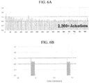
- FIGs. 6A and 6B show testing data of an implantation of a torque-limiting mechanism of the present disclosure.
- a torque-limiting driver that incorporated a torque-limiting mechanism having the torque-limiting interfaces shown in FIGs. 2, 3 , and 4A-4F formed from 30% glass-filled PEI resin was assembled and tested at 450 RPM with a predetermined torque limit of about 1.05 N-m.
- the torque-limiting driver was rotated at 450 RPM for 1 second intervals and the torque output was measured with an electronic torque transducer, FIG. 6A shows that the torque limit remained within an operational range of about 0.9 to about 1.1 N-mover approximately 2,200 actuations.
- FIG. 6B shows data for two 1-second intervals and shows the actuations that occur over those I-second intervals. Approximately 22 actuations, from 7.5 revolutions per second at 450 RPM, occur in each 1-second interval, with the applied torque remaining within the operational range.
- FIGs. 6C and 6D show the torque output profiles of torque-limiting drivers over a single hand-driven actuation.
- FIG. 6C shows the torque profile of a traditional crown gear interface with opposing sets of jagged teeth, such as that disclosed in U.S. Patent No. 7,938,046 .
- the resulting profile shows a spike drop-off in torque as the opposing teeth slip off each other sharply Systems incorporating these jagged teeth crown gears exhibit inconsistent torque-limits across ranges of rotational speeds, with higher rotational speeds showing higher torque.
- FIG. 6D shows a torque output profile from the system used in FIGs. 6A and 6B , which incorporates the three-undulation torque-limiting interfaces shown in FIGs. 2, 3 , 4A-4F and described more fully elsewhere herein.
- the torque output increases and decreases more gradually and smoothly through each actuation, which provides for a more consistent torque- limit across rotational speeds, including higher rotational speeds up to 1300 RPM. Further, the torque-limiting mechanisms are more durable and can last through a higher number of actuations, including over 2,000 actuations, while remaining within a specified operational range.
- each physical element disclosed should be understood to encompass a disclosure of the action which that physical element facilitates.
Description
- This disclosure relates to gearless torque drives for torque-limiting devices that are suitable for operation at high rotational speeds.
- Torque is a measure of force acting on an object that causes that object to rotate. In the case of a driver and a fastener, this measurement can be calculated mathematically in terms of the cross product of specific vectors:

- Where r is the vector representing the distance and direction from an axis of a fastener to a point where the force is applied and F is the force vector acting on the driver.
- Torque has dimensions of force times distance and the SI unit of torque is the Newton meter (N-m). The joule, which is the SI unit for energy or work, is also defined as an N-m, but this unit is not used for torque. Since energy can be thought of as the result of force times distance, energy is always a scalar whereas torque is force cross-distance and so is a vector-valued quantity. Other non-SI units of torque include pound-force-feet, foot-pounds-force, ounce-force-inches, meter-kilograms-force, inch-ounces or inch-pounds.
- Torque-limiting drivers are widely used throughout the medical industry. These torque-limiting drivers have a factory pre-set torque to ensure the accuracy and toughness required to meet a demanding surgical environment.
- The medical industry has made use of both reusable and disposable torque-limiting drivers. In a surgical context, there is little room for error and these drivers must impart a precise amount of torque.
- Reusable drivers require constant recalibration to ensure that the driver is imparting the precise amount of torque. Recalibration is a cumbersome task but must be done routinely Such reusable devices also require sterilization.
- Disposable drivers are an alternative to the reusable drivers. Once the driver has been used, it is discarded.
- Disposable drivers are traditionally used for low torque applications. The standard torque values in these applications typically range from about 0.028 N-m to about 0.14 N-m (about 4 to about 20 inch-ounces). It has, however, been a challenge to develop a reliable disposable driver capable of imparting higher torques for larger applications.
- Power tools are used for some applications in the medical industry. Such power tools can provide torque to a workpiece while also providing higher rotational rates than can be provided with manually driven tools. Torque-limiting systems can be utilized with medical power tools, either as an additional attachment provided in-line between the power tool and the workpiece or as internalized systems within the power tool itself Reusable torque-limiting systems need to be sterilized between uses and typically must be serviced and recalibrated periodically to ensure performance within specifications. Disposable torque-limiting systems are an alternative to the reusable systems. Once the torque-limiting system has been used. it is discarded.
-
WO2014/116414 describes a power driven in-line disposable torque limiting device. The device includes upper and lower shanks that each have teeth forming a crown gear. In use, the crown gear teeth of the shanks are engaged until a torque limit is exceeded. - Disposable torque limiting devices which are inexpensive for use with power tools can fall out of specification with increased RPMs and as such fail to perform sufficiently.
- Thus there is a need for disposable torque-limiting systems that can be utilized with medical power tools to limit applied torque at higher rotational speeds and remain in specification over a predetermined number of actuations. The disclosure is directed to these and other important needs.
- The present invention provides a torque limiting mechanism as defined in the appended claims. This disclosure provides torque-limiting mechanisms comprising an upper shank component, a lower shank component, and a biasing element. The upper shank component comprises an upper shank component comprising a proximal end, a distal end, an axial bore connecting the proximal end and the distal end, and a first torque-limiting interface disposed on the proximal end. The lower shank component comprising a proximal end, a distal end, a drive socket connecting the proximal end and the distal end, and a second torque-limiting interface disposed on the proximal end, wherein the upper shank component and the lower shank component are aligned along an axis in the direction of the axial bore and the drive socket with the first torque-limiting interface in contact with the second torque-limiting interface. The biasing element is configured to apply compressive force along the axis to compress the first torque-limiting interface against the second torque-limiting interface. The upper shank component and the lower shank component are configured to engage to rotate together when torque is applied to the lower shank component via the drive socket. The upper shank component and the lower shank component are configured to disengage when a predetermined torque limit is exceeded.
- This disclosure provides torque-limiting interfaces comprising a plurality of undulations arranged around an axial bore or drive socket and separated by a plurality of transition regions. Each undulation comprises an upslope, a peak, and a downslope. The inclination angle of each upslope can be about 3 to about 15 degrees, about 5 to about 9 degrees, about 6 to about 8 degrees, or about 7 degrees. The declination angle of each downslope can be 5 to 30 degrees, more preferably about 10 to about 20 degrees, and most preferably about 15 degrees. In accordance with the invention, each downslope has a declination angle of between 5 and 30 degrees.
- The above-mentioned features of the present disclosure will become more apparent with reference to the following description taken in conjunction with the accompanying drawings wherein like reference numerals denote like elements. In addition, the drawings are not necessarily drawn to scale. In the drawings:
-
Figure 1 shows an exploded assembly perspective view of some aspects of torque-limiting mechanisms of the present disclosure; -
Figure 2 shows a perspective view of some aspects of components of torque-limiting mechanisms of the present disclosure; -
Figure 3 shows a perspective view of some aspects of components of torque-limiting mechanisms of the presentdisclosure; -
Figure 4A shows a top view of some aspects of components of torque-limiting mechanisms of the present disclosure.Figures 4B, 4C, 4D, 4E, and 4F show cut-away sectional views along the sections marked A-A, B-B, C-C, D-D, and E-E inFigure 4A ; -
Figures 5A and 5B show perspective views of some aspects of components of torque-limiting mechanisms of the present disclosure.Figure 5C shows a side view of some aspects of components of torque-limiting mechanisms of the present disclosure.Figure 5D shows a cut-away section view along the section marked F-F inFigure 5C ; -
Figures 6A and 6B show testing data from testing of an implementation of the torque-limiting mechanisms of the present disclosure; -
Figure 6C shows testing data from testing of a prior art torque-limiting mechanism; and -
Figures 6D shows testing data from testing of an implementation of the torque-limiting mechanisms of the present disclosure. - As shall be appreciated by those having ordinary skill in the art, the figures are not to scale, and modifications to scale within a figure or across the figures are considered within the present disclosure.
-
FIGs. 1 ,2, and 3 shows some aspects of some implementations of torque-limiting mechanisms of the present disclosure. The torque-limiting mechanisms can have anupper shank component 200, alower shank component 100, and a biasing element 300 (not shown) configured to apply a force (F) along anaxis 50.Upper shank component 200 can have aproximal end 201, adistal end 202, anaxial bore 210 connecting the proximal end and the distal end, and a torque-limitinginterface 250 disposed on the proximal end.Lower shank component 100 can have aproximal end 101, adistal end 102, adrive socket 110 connecting the proximal end and the distal end, and a torque-limitinginterface 150 disposed on the proximal end. The upper shank component and the lower shank component are aligned along anaxis 50 in the direction of theaxial bore 210 and thedrive socket 110 with the torque-limitinginterface 250 in contact with the torque-limitinginterface 150. The biasingelement 300 is configured to apply a compressive force (F) along the axis to compress the torque-limiting interface against the torque-limiting interface. Theupper shank component 200 and thelower shank component 100 are configured to engage to rotate together when torque is applied to the lower shank component via the drive socket and are configured to disengage when a predetermined torque limit is exceeded. When disengaged, the torque-limitinginterfaces 150/250 slide past each other in relative rotation about theaxis 50.Drive socket 110 can have any suitable shape that allows for the transmission of torque to thelower shank component 100. Suitable shapes for thedrive socket 110 include geometric shape profiles such as hexagons, squares, or truncated/rounded versions thereof. - Those of ordinary skill in the art can appreciate that the torque-limiting mechanisms of the present disclosure can be incorporated into any systems or devices that require torque-limited rotation between subcomponents of those systems or devices. In some implementations, the torque-limiting mechanisms of the present disclosure can be incorporated into torque-limited drivers for use in surgical applications: such drivers can be hand-driven or driven with power tools at higher rates of rotation.
-
FIGs. 2 and 3 show further aspects of some implementations.Upper shank component 200 can have a torque-limitinginterface 250 with a plurality ofundulations 220 arranged around the axial bore and separated by a plurality oftransition regions 224. Thelower shank component 100 can shave a torque-limitinginterface 150 having a plurality ofundulations 120 arranged around the drive socket and separated by a plurality oftransition regions 124, the first and second pluralities being equal in number. Eachundulation 120/220 can be formed as an upslope 121/221, apeak 122/222, and a downslope 123/223. - In some implementations, the torque-limiting
interfaces 150/250 do not contain any step or drop-off greater than about 0.0127cm (0.005"). One or more cutouts or slots (not shown) can be provided in one or more of the upslopes, 121/221,peaks 122/222, ordownslopes 123/223 to collect at least a portion of any debris generated during operation. In some embodiments, downslope 123/223 is designed with maximum length to provide the softest downward angle back down to the initial height of thenext upslope 121/221 During powered rotation, a softer downslope mitigates degradation of the downslope 123/223 material. Such degradation adversely impact performance as the torque-limit at which disengagement occurs can change as the material degrades. - Each
undulation 120/220 sweeps through a portion of the 360 degrees around the centralaxial bore 210 or drive socket 11, with the plurality ofundulations 120/220 covering a total portion of the 360 degrees around the central axial bore. In some implementations, the total portion covered by the plurality ofundulations 120/220 can be at least about 65% of the 360 degrees (about 235 degrees), at least about 70% of the 360 degrees (about 255 degrees), at least about 80% of the 360 degrees (about 285 degrees), at least about 83% of the 360 degrees (about 300 degrees), at least about 90% of the 360 degrees (about 324 degrees), at least about 95% of the 360 degrees (about 345 degrees), or at least about 98% of the 360 degrees (about 350 degrees). The portion not covered by the plurality ofundulations 120/220 is filled withtransition regions 124/224 between the end of each downslope 123/223 and the beginning of thenext upslope 121/221. Eachtransition region 124/224 can be selected to be no greater than about 35 degrees, no greater than about 20 degrees, no greater than about 15 degrees, no greater than about 10 degrees, no greater than about 5 degrees, no greater than about 4 degrees, no greater than about 3 degrees, no greater than about 2 degrees, no greater than about 1 degree, or can be eliminated entirely if the end of each downslope 123/223 is immediately adjacent to the beginning of thenext upslope 121/221. - A softer downslope angle the torque-limiting
interfaces 150/250 can substantially mitigate or eliminate any "click" or audible indication that theupper shank component 200 andlower shank component 100 have slipped past each other during a disengagement, also referred to herein as an actuation, when the predetermined torque limit has been exceeded. In some implementations, an actuation indicating system can be incorporated in the overall torque-limiting driver to create one or more "clicks" when theupper shank component 200 andlower shank component 100 have slipped past each other. In some implementations, the actuation indicating system can include a flag feature on eitherlower shank component 100 orupper shank component 200 that impacts one or more spokes, protrusions, or other physical features on another component in the system as relative rotation occurs. -
Upper shank component 200 andlower shank component 100 can be formed from various materials. Suitable materials include stainless steels, aluminums, plastic materials, or composites including plastic. Plastic and other economical equivalents improve cost efficiency of production while providing high tensile strength, resistance to deformation, etc. Effective materials include plastics, resins, polymers, imides, fluoropolymers, thermoplastic polymers, thermosetting plastics, and the like as well as blends or mixtures thereof. In some implementations, 30% glass-filled polyetherimide can be used to form one or more of the above components. For components formed from stainless steels or aluminums, the shank components can be heat treated, passivated, or anodized via suitable methods known to those of ordinary skill in the art. In some implementations, aluminum shank components can be finished with a hard anodize finish per MIL-A-8625F, type III, class 2. In some implementations, stainless steel 440c shank components can be heat treated per AMS 2759/5D to 58Rc and passivated with treatment with nitric acid and/or sodium dichromate. Other heat treatments and passivation methods known in the art are also suitable. In some implementations, corresponding pairs of gear rings are formed from different materials. In some preferred implementations, oneshank component 100/200 is formed from stainless steel or aluminum and the corresponding gear ring is formed from 30% glass-filled polyetherimide (PEI) resin. In some implementations theshank components 100/200 can be made from the same material. - According to aspects of one or more exemplary implementations, components of the torque-limiting mechanisms of the present disclosure are resistant to sterilization, cleaning, and preparation operations. For example, the upper shank component and lower shank component may be configured to withstand sterilization by methods including radiation (e.g., gamma rays, electron beam processing), steam (e.g., autoclave:), detergents, chemical (e.g., Ethylene Oxide), heat, pressure, inter aha. For example, materials may be selected according to resistance to one or more selected sterilization techniques.
- The material selection and surface treatments applied to the torque-limiting
interfaces 150/250 can affect the predetermined torque limit. The static friction between the torque-limitinginterfaces 150/250 determines when disengagement will occur, as the rotation force can overcome: the static friction holding the interfaces into engagement with each other. Greater contact surface area of the opposing interfaces, viawider undulations 120/220 or other aspects of the shape/profile of theundulations 120/220, will increase the resistance: to actuation and lead to a higher predetermined torque limit. - In some preferred implementations,
upper shank component 200 andlower shank component 200 are both made from 30% glass-filled polyetherimide: (PEI) resin. In some implementations, a glass-filled ULTEM® PEI from Saudi Basic Industries Corporation (SABIC) can be used to form theupper shank component 200 andlower shank component 200 via machining or molding. In some implementations, a lubricant is disposed on one or both of torque-limitinginterfaces 150/250. Such lubricants are useful to avoid excessive heat buildup during actuations at high rates of rotation, which can melt or degrade the PEI material. - The shape of some implementations of
undulations 120/220 can be seen inFIGs. 4A-4F. FIG. 4A shows a top view of the torque-limitinginterface 150 at theproximal end 201 ofupper shank component 200.FIG. 4B shows a cut-away view of theupper shank component 200 along line A-A shown inFIG. 4A. FIG. 4C shows a cut-away view of theupper shank component 200 along line B-B shown inFIG. 4A. FIG. 4D shows a cut-away view of theupper shank component 200 along line C-C shown inFIG. 4A, FIG. 4E shows a cut-away- view of theupper shank component 200 along line E-E shown inFIG. 4A. FIG. 4F shows a cut-away view of theupper shank component 200 along line D-D shown inFIG. 4A . The number ofundulations 120/220 is determined by the size of theupper shank component 200 andlower shank component 100 and the shape of theundulations 120/220, The size of theshank components 100/200 determines the functional path length that the plurality of undulations may have. The functional path length refers to the circumferential length of a circular path along the midpoint of the undulations, shown as a dashedcircle 227 inFIG. 4A , A larger diameter shank component allows for a larger functional path length. The shape of theundulations 120/220 refers to the inclination angle of the upslope 121/221, the length of thepeak 122/222, and the declination angle of the downslope 123/223. Sharper inclination and declination angles and shorter peak lengths can lead to a shorter functional path length for each individual undulation, which would allow for more undulations to be placed onto the torque -limitinginterfaces 150/250. The torque-limiting interfaces may have two undulations, three undulations, four undulations, or five or more undulations. Three or more undulations are used in some preferred implementations, as systems with only two undulations may be less stable during actuations at higher rates of rotation. - The width of the undulations can span the entirety of the annular ring of the proximal ends of the upper shank component and lower shank component between the
drive socket 110 oraxial bore 210 and outer edges of those components, or can be reduced widths to accommodate adjoining parts to avoid undesired contact points or friction. The width must be sufficient to provide adequate interface contact area with die opposing set of waves to create the friction necessary for torque transmission. Larger widths allow for the applied force to be distributed over larger surface areas and reduce stress on the components. - The inclination angle of each upslope 121/221 can be about 3 to about 15 degrees, more preferably about 5 to about 9 degrees, more preferably about 6 to about 8 degrees, and most preferably about 7 degrees. The inclination angle is measured along the functional path length along the midpoint of the undulations, as the angle along the
interior edge 126/226 will be higher due to the shorter path length, and the angle along theexterior edge 125/225 will be lower due to the longer path length. The declination angle of each downslope 123/223 can be to 30 degrees, more preferably about 10 to about 20 degrees, and most preferably about 15 degrees. In accordance with the invention, each downslope has a declination angle of between 5 and 30 degrees. The declination angle is measured along the functional path length along the midpoint of the undulations. In some preferred implementations, the ratio of the functional path length of the upslope 121/221 of each undulation to the functional path length of the downslope of each undulation can be about 3.0:1, about 2.5:1, about 2.4:1, about 2.3:1, about 2.2:1, about 2.1:1, about 2.0:1, about1.9:1, about 1.8:1, about 1.7:1, about 1.6:1, about 1.5:1, about 1.4:1, about 1.3:1, about 1.2:1, about 1.1:1, or about 1.0:1. In some preferred implementations the ratio can be between about 2.2:1 and about 1.8: 1 or more preferably about 2.0:1. - Each
peak 122/222 has an even height across its surface from theinterior edge 126/226 to theexterior edge 125/225 at each radial line from the central axis of therespective shank component 100/200. In some implementations the functional path length of each peak 122/222 is approximately equal to the length of each of thetransition regions 124/224, such that thepeaks 122/222 of each torque-limiting interface are complementary and mate with thetransition regions 124/224 of the opposing torque-limiting interface. -
FIGs. 5A-5D show some aspects of an implementation of alower shank component 100 the present disclosure.FIG 5A and FIG. 5B show perspective views of an implementation of alower shank component 100.FIG. 5C shows a side view whileFIG. 5D shows a cross-sectional view along the line D-D shown inFIG. 5C . Thelower shank component 100 can include a retainingcavity 103 configured to retain biasing element 300 (not shown) within awall 104 located at thedistal end 102. The retainingcavity 103 provides for a volume in which abiasing element 300 can be compressed, so that if biasingelement 300 expands radially during compression it will be retained within retainingcavity 103 rather than impinging or contacting other components within the system. -
Biasing element 300 provides compressive force between the upper shank component and lower shank component to place the torque-limitinginterfaces 150/250 into frictional contact with each other. Suitable biasing elements can include springs, spring washers, also referred to as Belleville washers, grommets or washers of compressible materials such as rubber. In some implementations, compressible materials with durometer ratings between about 50 durometer and 100 durometer can be used as biasing elements. The biasingelement 300 can be compressed by other components in a torque-limiting driver. The amount of compression applied to a biasing element can be used to set the predetermined torque limit at which disengagement/actuation of the torque-limiting mechanism occurs. Higher compressive forces created by the biasing element will create higher predetermined torque limits. - According to aspects of one or more exemplary implementations, the torque-limiting mechanisms of the present disclosure are capable of imparting torques of up to about 6 N-m at various rotational speeds. For example, the torque output range may be selected between about 0.5 N-m and about 6 N-m and utilized in combination with a rotational speed selected between about 150 RPMs and about 1300 RPMs. Typically, the torque requirement is different for different operations and for different implants. For example, applications may include those in the field of orthopedic surgery, construction and emplacement of implants, etc. In such instances, the predetermined torque limit may be about 6 N-m, depending on an implant's specifications. Smaller fasteners may utilize lower torque limits between about 0.1 N-m and about 2.0 N-m. In some instances the torque-limiting mechanisms of the present disclosure will provide a predetermined torque of at least one of 0.1,0.2,0.3,0.4,0.5,0.6, 0.7, 0.8, 0.9, 1.0, 1.1, 1.2, 1.3, 1.4, 1.5, 1.6, 1.7, 1.8, 1.9, 2.0, 2.1, 2.2, 2.3, 2.4, 2.5, 2.6, 2.7, 2.8, 2.9, 3.0, 3.1, 3.2, 3.3, 3.4, 3.5, 3.6, 3.7, 3.8, 3.9, 4.0, 4.1, 4.2, 4.3, 4.4, 4.5, 4.6, 4.7, 4.8, 4.9, 5.0, 5.1, 5.2, 5.3, 5.4, 5.5, 5.6, 5.7, 5.8, 5.9, or 6.0 Newton-meters (N-m) of torque at a rotational speed of at least one of 50, 100, 150, 200, 250, 300, 350, 400, 450, 500, 550, 600, 650, 700, 750, 800, 850, 900, 950, 1000, 1050, 1100, 1150, 1200, 1250, or 1300 RPMs over at least one of 5, 10, 20, 30, 40, 50, 60, 70, 80, 90, 100, 105, 110, 120, 150, 180, 200, 220, 250, 300, 350, 400, 450, 500, 550, 600, 650, 700, 750, 800, 850, 900, 950, 1000, 1050, 1100,1150, 1200, 1250, 1300, 1350, 1400, 1450, 1500, 1550, 1600, 1650, 1700, 1750, 1800, 1850,1900, 1950, or 2000 actuations while remaining within a specified operational range.
-
FIGs. 6A and 6B show testing data of an implantation of a torque-limiting mechanism of the present disclosure. A torque-limiting driver that incorporated a torque-limiting mechanism having the torque-limiting interfaces shown inFIGs. 2, 3 , and4A-4F formed from 30% glass-filled PEI resin was assembled and tested at 450 RPM with a predetermined torque limit of about 1.05 N-m. The torque-limiting driver was rotated at 450 RPM for 1 second intervals and the torque output was measured with an electronic torque transducer,FIG. 6A shows that the torque limit remained within an operational range of about 0.9 to about 1.1 N-mover approximately 2,200 actuations.FIG. 6B shows data for two 1-second intervals and shows the actuations that occur over those I-second intervals. Approximately 22 actuations, from 7.5 revolutions per second at 450 RPM, occur in each 1-second interval, with the applied torque remaining within the operational range. -
FIGs. 6C and 6D show the torque output profiles of torque-limiting drivers over a single hand-driven actuation.FIG. 6C shows the torque profile of a traditional crown gear interface with opposing sets of jagged teeth, such as that disclosed inU.S. Patent No. 7,938,046 . The resulting profile shows a spike drop-off in torque as the opposing teeth slip off each other sharply Systems incorporating these jagged teeth crown gears exhibit inconsistent torque-limits across ranges of rotational speeds, with higher rotational speeds showing higher torque. In contrast,FIG. 6D shows a torque output profile from the system used inFIGs. 6A and 6B , which incorporates the three-undulation torque-limiting interfaces shown inFIGs. 2, 3 ,4A-4F and described more fully elsewhere herein. The torque output increases and decreases more gradually and smoothly through each actuation, which provides for a more consistent torque- limit across rotational speeds, including higher rotational speeds up to 1300 RPM. Further, the torque-limiting mechanisms are more durable and can last through a higher number of actuations, including over 2,000 actuations, while remaining within a specified operational range. - It should also be understood that a variety of changes may be made without departing from the essence of the disclosure. Such changes are also implicitly included in the description. They still fall within the scope of this disclosure. It should be understood that this disclosure is intended to yield a patent covering numerous aspects of the disclosure both independently and as an overall system and in both method and apparatus modes.
- Further, each of the various elements of the disclosure and claims may also be achieved in a variety of manners. This disclosure should be understood to encompass each such variation, be it a variation of an implementation of any apparatus implementation, a method or process implementation, or even merely a variation of any element of these.
- Particularly, it should be understood that as the disclosure relates to elements of the disclosure, the words for each element may be expressed by equivalent apparatus terms or method terms -- even if only the function or result is the same.
- Such equivalent, broader, or even more generic terms should be considered to be encompassed in the description of each element or action. Such terms can be substituted where desired to make explicit the implicitly broad coverage to which this disclosure is entitled.
- It should be understood that all actions may be expressed as a means for taking that action or as an element which causes that action.
- Similarly, each physical element disclosed should be understood to encompass a disclosure of the action which that physical element facilitates.
Claims (15)
- A torque-limiting mechanism comprising:an upper shank component (200) comprising a proximal end (201), a distal end (202), an axial bore (210) connecting the proximal end and the distal end, and a first undulated torque-limiting interface (250) disposed on the proximal end;a lower shank component (100) comprising a proximal end (101), a distal end (102), a drive socket (110) connecting the proximal end and the distal end, and a second undulated torque-limiting interface (150) disposed on the proximal end, wherein the upper shank component and the lower shank component are aligned along an axis (50) in the direction of the axial bore and the drive socket with the first torque-limiting interface in contact with the second torque-limiting interface; anda compressible biasing element (300) with a 50 to 100 durometer rating configured to apply compressive force (F) along the axis to compress the first torque-limiting interface against the second torque-limiting interface;wherein the upper shank component and the lower shank component are configured to engage to rotate together when torque is applied to the lower shank component via the drive socket;wherein the upper shank component and the lower shank component are configured to disengage when a predetermined torque limit is exceeded;the first torque-limiting interface comprises a first plurality of undulations (220) arranged around the axial bore and separated by a first plurality of transition regions (224);the second torque-limiting interface comprises a second plurality of undulations (120) arranged around the drive socket and separated by a second plurality of transition regions (124); andeach undulation comprises an upslope (121/221), a peak (122/222), and a downslope (123/223), characterised in that each downslope has a declination angle of between 5 and 30 degrees such that degradation is mitigated between the first and second pluralities of undulations.
- The torque-limiting mechanism of claim 1 wherein:
each upslope has an inclination angle between about 3 degrees and about 15 degrees. - The torque-limiting mechanism of claim 1 wherein:
each upslope has an inclination angle between about 5 degrees and about 9 degrees. - The torque-limiting mechanism of claim 1 wherein:
each upslope has an inclination angle between about 6 degrees and about 8 degrees. - The torque-limiting mechanism of claim 1 wherein:
each upslope has an inclination angle of about 7 degrees. - The torque-limiting mechanism of claim 1 wherein the predetermined torque limit is between about 0.1 Newton-meter and 3.0 Newton-meter.
- The torque-limiting mechanism of claim 1 wherein the predetermined torque limit is between about 3.0 Newton-meter and 6.0 Newton-meter.
- The torque-limiting mechanism of claim 1 wherein the first torque-limiting interface and second torque-limiting interface each comprise three undulations.
- The torque-limiting mechanism of claim 1 wherein the first torque-limiting interface and second torque-limiting interface each comprise four undulations.
- The torque-limiting mechanism of claim 1 wherein the first torque-limiting interface and second torque-limiting interface each comprise five undulations.
- The torque-limiting mechanism of claim 1 wherein the torque-limiting mechanism provides a predetermined torque between about 0.1 Newton-meter and about 6 Newton-meters of torque at a rotational speed between about 50 RPM and about 1300 RPM over at least one of 5, 10, 20, 30, 40, 50, 60, 70, 80, 90, 100, 105, 110, 120, 150, 180, 200, 220, 250, 300, 350, 400, 450, 500, 550, 600, 650, 700, 750, 800, 850, 900, 950, 1000, 1050, 1100, 1150, 1200, 1250,1300, 1350, 1400, 1450, 1500, 1550, 1600, 1650, 1700, 1750, 1800, 1850, 1900, 1950, 2000, 2100, 2200, 2300, 2400, or 2500 actuations while remaining within a specified operational range.
- The torque-limiting mechanism of claim 1 wherein the torque-limiting interfaces do not contain any step or drop-off greater than 0.0127cm (0.005 inch).
- The torque-limiting mechanism of claim 1, wherein the upper and lower shank components (200, 100) comprise plastic materials.
- The torque-limiting mechanism of claim 1, wherein the upper and lower shank components (200, 100) comprise polymer or resin materials.
- The torque-limiting mechanism of claim 1, wherein the upper and lower shank components (200, 100) comprise 30% glass-filled polyetherimide.
Applications Claiming Priority (2)
| Application Number | Priority Date | Filing Date | Title |
|---|---|---|---|
| US201562238359P | 2015-10-07 | 2015-10-07 | |
| PCT/US2016/035707 WO2017062068A1 (en) | 2015-10-07 | 2016-06-03 | Gearless torque drive |
Publications (3)
| Publication Number | Publication Date |
|---|---|
| EP3359837A1 EP3359837A1 (en) | 2018-08-15 |
| EP3359837A4 EP3359837A4 (en) | 2019-07-24 |
| EP3359837B1 true EP3359837B1 (en) | 2021-08-11 |
Family
ID=58488172
Family Applications (1)
| Application Number | Title | Priority Date | Filing Date |
|---|---|---|---|
| EP16854016.9A Active EP3359837B1 (en) | 2015-10-07 | 2016-06-03 | Gearless torque drive |
Country Status (3)
| Country | Link |
|---|---|
| US (1) | US10920833B2 (en) |
| EP (1) | EP3359837B1 (en) |
| WO (1) | WO2017062068A1 (en) |
Families Citing this family (2)
| Publication number | Priority date | Publication date | Assignee | Title |
|---|---|---|---|---|
| WO2017062068A1 (en) | 2015-10-07 | 2017-04-13 | Eca Medical Instruments | Gearless torque drive |
| WO2022076895A1 (en) | 2020-10-09 | 2022-04-14 | Milwaukee Electric Tool Corporation | Clutch socket adapter for a tool |
Family Cites Families (30)
| Publication number | Priority date | Publication date | Assignee | Title |
|---|---|---|---|---|
| US4311224A (en) * | 1978-08-24 | 1982-01-19 | Kabushiki Kaisha Sankyo Seisakujo | Torque limiter |
| US4272973A (en) * | 1979-04-26 | 1981-06-16 | Fu Tsai Lee | Socket joint for torque wrench |
| US4678452A (en) * | 1985-07-26 | 1987-07-07 | Performance Feeders, Inc. | Overload release clutch |
| US5366412A (en) * | 1992-05-19 | 1994-11-22 | Implant Innovations, Inc. | Torque limiting clutch and its uses |
| US5947214A (en) * | 1997-03-21 | 1999-09-07 | Baker Hughes Incorporated | BIT torque limiting device |
| US6082941A (en) * | 1999-01-18 | 2000-07-04 | Rubber-Fab, Inc. | Torque-limiting fastener |
| US6132435A (en) * | 1999-09-14 | 2000-10-17 | Synthes (Usa) | Torque limiting device for surgical use |
| SE513457C2 (en) * | 1999-10-11 | 2000-09-18 | Kapman Ab | Torque limited screwdriver |
| WO2003017857A1 (en) * | 2001-08-23 | 2003-03-06 | Synthes Ag Chur | Device for limiting torque to be transferred |
| DE10341697B3 (en) * | 2003-09-10 | 2004-10-07 | Felo-Werkzeugfabrik Holland-Letz Gmbh | Screwdriver used as a hand screwdriver comprises couplings each consisting of a locking bushing, a catch bushing and a pressure spring with a pre-tension between the couplings on a toothed casing |
| US6948410B1 (en) * | 2004-03-04 | 2005-09-27 | Precision Instruments, Inc. | Torque wrench with sleeve for locking rotatable handle |
| DE102004030760A1 (en) * | 2004-06-25 | 2006-01-19 | Robert Bosch Gmbh | Device with a torque limiting unit |
| US7243581B1 (en) * | 2006-06-20 | 2007-07-17 | Bradshaw Medical | Fixed torque limiting driver |
| US8083596B1 (en) * | 2007-11-26 | 2011-12-27 | Holmed Corporation | Torque limiter |
| FR2924641B1 (en) * | 2007-12-10 | 2010-03-19 | Salomon Sa | FAST CLAMPING SYSTEM FOR CYCLE WITH CHECKING TORQUE CONTROL |
| US8241363B2 (en) * | 2007-12-19 | 2012-08-14 | Depuy Spine, Inc. | Expandable corpectomy spinal fusion cage |
| US9017333B2 (en) * | 2008-04-17 | 2015-04-28 | Warsaw Orthopedic, Inc. | Surgical tool |
| US7762164B2 (en) | 2008-06-02 | 2010-07-27 | Eca Medical Instruments | Torque-limiting device |
| US8359955B2 (en) * | 2010-03-23 | 2013-01-29 | Francois Deneault | Torque socket |
| US8365641B2 (en) * | 2010-05-12 | 2013-02-05 | Terry Daglow | Torque wrench |
| US9162350B2 (en) * | 2010-07-28 | 2015-10-20 | Eca Medical Instruments | Robust nose torque-limiting device |
| DE102011080800A1 (en) * | 2011-08-11 | 2013-02-14 | Hilti Aktiengesellschaft | Hand tool |
| TWM439546U (en) * | 2012-06-29 | 2012-10-21 | Wei-Chieh Chuang | Non-return ratchet type torque socket |
| US20140123819A1 (en) * | 2012-11-06 | 2014-05-08 | Idex Health & Science Llc | Torque Limiting Tool and Methods |
| EP2948093B1 (en) * | 2013-01-23 | 2019-04-10 | ECA Medical Instruments | In-line disposable torque limiting device suitable for power drive |
| US9693814B2 (en) * | 2013-03-14 | 2017-07-04 | DePuy Synthes Products, Inc. | Torque limiting instrument, system and related methods |
| TWM473901U (en) * | 2013-12-03 | 2014-03-11 | xiu-mei Chen | Adapter structure of power hand tool |
| US9169914B2 (en) * | 2014-03-07 | 2015-10-27 | Gates Corporation | Isolating decoupler |
| US9731407B1 (en) * | 2014-05-23 | 2017-08-15 | Dallas G. Edmisten | T handle torque wrench with slip function |
| WO2017062068A1 (en) | 2015-10-07 | 2017-04-13 | Eca Medical Instruments | Gearless torque drive |
-
2016
- 2016-06-03 WO PCT/US2016/035707 patent/WO2017062068A1/en active Application Filing
- 2016-06-03 EP EP16854016.9A patent/EP3359837B1/en active Active
-
2018
- 2018-04-05 US US15/946,284 patent/US10920833B2/en active Active
Also Published As
| Publication number | Publication date |
|---|---|
| US10920833B2 (en) | 2021-02-16 |
| WO2017062068A1 (en) | 2017-04-13 |
| EP3359837A4 (en) | 2019-07-24 |
| EP3359837A1 (en) | 2018-08-15 |
| US20180223911A1 (en) | 2018-08-09 |
Similar Documents
| Publication | Publication Date | Title |
|---|---|---|
| EP3359341B1 (en) | Gearless spring washer high torque device | |
| EP3359839B1 (en) | Gearless compact torque drive | |
| US10343269B2 (en) | Hypocycloid reduction gearless spring washer torque limiting device | |
| EP2969395B1 (en) | Ratcheting torque wrench | |
| EP2948093B1 (en) | In-line disposable torque limiting device suitable for power drive | |
| EP2675595B1 (en) | International application for enhanced high torque device | |
| EP2566411B1 (en) | Ultra high torque device | |
| EP3703910B1 (en) | Single use speed reduction and torque limiting device | |
| US10920833B2 (en) | Gearless torque drive | |
| EP2948078B1 (en) | Fortified plastic disposable torque devices |
Legal Events
| Date | Code | Title | Description |
|---|---|---|---|
| STAA | Information on the status of an ep patent application or granted ep patent |
Free format text: STATUS: THE INTERNATIONAL PUBLICATION HAS BEEN MADE |
|
| PUAI | Public reference made under article 153(3) epc to a published international application that has entered the european phase |
Free format text: ORIGINAL CODE: 0009012 |
|
| STAA | Information on the status of an ep patent application or granted ep patent |
Free format text: STATUS: REQUEST FOR EXAMINATION WAS MADE |
|
| 17P | Request for examination filed |
Effective date: 20180420 |
|
| AK | Designated contracting states |
Kind code of ref document: A1 Designated state(s): AL AT BE BG CH CY CZ DE DK EE ES FI FR GB GR HR HU IE IS IT LI LT LU LV MC MK MT NL NO PL PT RO RS SE SI SK SM TR |
|
| AX | Request for extension of the european patent |
Extension state: BA ME |
|
| DAV | Request for validation of the european patent (deleted) | ||
| DAX | Request for extension of the european patent (deleted) | ||
| A4 | Supplementary search report drawn up and despatched |
Effective date: 20190626 |
|
| RIC1 | Information provided on ipc code assigned before grant |
Ipc: B25B 23/14 20060101ALI20190619BHEP Ipc: A61B 17/16 20060101ALI20190619BHEP Ipc: A61B 17/00 20060101ALI20190619BHEP Ipc: B25B 23/147 20060101ALI20190619BHEP Ipc: A61B 90/00 20160101ALI20190619BHEP Ipc: B25B 23/145 20060101ALI20190619BHEP Ipc: A61B 17/88 20060101ALI20190619BHEP Ipc: F16D 7/04 20060101ALI20190619BHEP Ipc: F16D 43/21 20060101AFI20190619BHEP |
|
| GRAP | Despatch of communication of intention to grant a patent |
Free format text: ORIGINAL CODE: EPIDOSNIGR1 |
|
| STAA | Information on the status of an ep patent application or granted ep patent |
Free format text: STATUS: GRANT OF PATENT IS INTENDED |
|
| INTG | Intention to grant announced |
Effective date: 20210302 |
|
| RAP3 | Party data changed (applicant data changed or rights of an application transferred) |
Owner name: ECA MEDICAL INSTRUMENTS |
|
| GRAS | Grant fee paid |
Free format text: ORIGINAL CODE: EPIDOSNIGR3 |
|
| GRAA | (expected) grant |
Free format text: ORIGINAL CODE: 0009210 |
|
| STAA | Information on the status of an ep patent application or granted ep patent |
Free format text: STATUS: THE PATENT HAS BEEN GRANTED |
|
| AK | Designated contracting states |
Kind code of ref document: B1 Designated state(s): AL AT BE BG CH CY CZ DE DK EE ES FI FR GB GR HR HU IE IS IT LI LT LU LV MC MK MT NL NO PL PT RO RS SE SI SK SM TR |
|
| REG | Reference to a national code |
Ref country code: CH Ref legal event code: EP |
|
| REG | Reference to a national code |
Ref country code: DE Ref legal event code: R096 Ref document number: 602016062161 Country of ref document: DE |
|
| REG | Reference to a national code |
Ref country code: IE Ref legal event code: FG4D Ref country code: AT Ref legal event code: REF Ref document number: 1419678 Country of ref document: AT Kind code of ref document: T Effective date: 20210915 |
|
| REG | Reference to a national code |
Ref country code: LT Ref legal event code: MG9D |
|
| REG | Reference to a national code |
Ref country code: NL Ref legal event code: MP Effective date: 20210811 |
|
| REG | Reference to a national code |
Ref country code: AT Ref legal event code: MK05 Ref document number: 1419678 Country of ref document: AT Kind code of ref document: T Effective date: 20210811 |
|
| PG25 | Lapsed in a contracting state [announced via postgrant information from national office to epo] |
Ref country code: BG Free format text: LAPSE BECAUSE OF FAILURE TO SUBMIT A TRANSLATION OF THE DESCRIPTION OR TO PAY THE FEE WITHIN THE PRESCRIBED TIME-LIMIT Effective date: 20211111 Ref country code: AT Free format text: LAPSE BECAUSE OF FAILURE TO SUBMIT A TRANSLATION OF THE DESCRIPTION OR TO PAY THE FEE WITHIN THE PRESCRIBED TIME-LIMIT Effective date: 20210811 Ref country code: LT Free format text: LAPSE BECAUSE OF FAILURE TO SUBMIT A TRANSLATION OF THE DESCRIPTION OR TO PAY THE FEE WITHIN THE PRESCRIBED TIME-LIMIT Effective date: 20210811 Ref country code: FI Free format text: LAPSE BECAUSE OF FAILURE TO SUBMIT A TRANSLATION OF THE DESCRIPTION OR TO PAY THE FEE WITHIN THE PRESCRIBED TIME-LIMIT Effective date: 20210811 Ref country code: ES Free format text: LAPSE BECAUSE OF FAILURE TO SUBMIT A TRANSLATION OF THE DESCRIPTION OR TO PAY THE FEE WITHIN THE PRESCRIBED TIME-LIMIT Effective date: 20210811 Ref country code: HR Free format text: LAPSE BECAUSE OF FAILURE TO SUBMIT A TRANSLATION OF THE DESCRIPTION OR TO PAY THE FEE WITHIN THE PRESCRIBED TIME-LIMIT Effective date: 20210811 Ref country code: PT Free format text: LAPSE BECAUSE OF FAILURE TO SUBMIT A TRANSLATION OF THE DESCRIPTION OR TO PAY THE FEE WITHIN THE PRESCRIBED TIME-LIMIT Effective date: 20211213 Ref country code: NO Free format text: LAPSE BECAUSE OF FAILURE TO SUBMIT A TRANSLATION OF THE DESCRIPTION OR TO PAY THE FEE WITHIN THE PRESCRIBED TIME-LIMIT Effective date: 20211111 Ref country code: SE Free format text: LAPSE BECAUSE OF FAILURE TO SUBMIT A TRANSLATION OF THE DESCRIPTION OR TO PAY THE FEE WITHIN THE PRESCRIBED TIME-LIMIT Effective date: 20210811 Ref country code: RS Free format text: LAPSE BECAUSE OF FAILURE TO SUBMIT A TRANSLATION OF THE DESCRIPTION OR TO PAY THE FEE WITHIN THE PRESCRIBED TIME-LIMIT Effective date: 20210811 |
|
| PG25 | Lapsed in a contracting state [announced via postgrant information from national office to epo] |
Ref country code: PL Free format text: LAPSE BECAUSE OF FAILURE TO SUBMIT A TRANSLATION OF THE DESCRIPTION OR TO PAY THE FEE WITHIN THE PRESCRIBED TIME-LIMIT Effective date: 20210811 Ref country code: LV Free format text: LAPSE BECAUSE OF FAILURE TO SUBMIT A TRANSLATION OF THE DESCRIPTION OR TO PAY THE FEE WITHIN THE PRESCRIBED TIME-LIMIT Effective date: 20210811 Ref country code: GR Free format text: LAPSE BECAUSE OF FAILURE TO SUBMIT A TRANSLATION OF THE DESCRIPTION OR TO PAY THE FEE WITHIN THE PRESCRIBED TIME-LIMIT Effective date: 20211112 |
|
| PG25 | Lapsed in a contracting state [announced via postgrant information from national office to epo] |
Ref country code: NL Free format text: LAPSE BECAUSE OF FAILURE TO SUBMIT A TRANSLATION OF THE DESCRIPTION OR TO PAY THE FEE WITHIN THE PRESCRIBED TIME-LIMIT Effective date: 20210811 |
|
| PG25 | Lapsed in a contracting state [announced via postgrant information from national office to epo] |
Ref country code: DK Free format text: LAPSE BECAUSE OF FAILURE TO SUBMIT A TRANSLATION OF THE DESCRIPTION OR TO PAY THE FEE WITHIN THE PRESCRIBED TIME-LIMIT Effective date: 20210811 |
|
| REG | Reference to a national code |
Ref country code: DE Ref legal event code: R097 Ref document number: 602016062161 Country of ref document: DE |
|
| PG25 | Lapsed in a contracting state [announced via postgrant information from national office to epo] |
Ref country code: SM Free format text: LAPSE BECAUSE OF FAILURE TO SUBMIT A TRANSLATION OF THE DESCRIPTION OR TO PAY THE FEE WITHIN THE PRESCRIBED TIME-LIMIT Effective date: 20210811 Ref country code: SK Free format text: LAPSE BECAUSE OF FAILURE TO SUBMIT A TRANSLATION OF THE DESCRIPTION OR TO PAY THE FEE WITHIN THE PRESCRIBED TIME-LIMIT Effective date: 20210811 Ref country code: RO Free format text: LAPSE BECAUSE OF FAILURE TO SUBMIT A TRANSLATION OF THE DESCRIPTION OR TO PAY THE FEE WITHIN THE PRESCRIBED TIME-LIMIT Effective date: 20210811 Ref country code: EE Free format text: LAPSE BECAUSE OF FAILURE TO SUBMIT A TRANSLATION OF THE DESCRIPTION OR TO PAY THE FEE WITHIN THE PRESCRIBED TIME-LIMIT Effective date: 20210811 Ref country code: CZ Free format text: LAPSE BECAUSE OF FAILURE TO SUBMIT A TRANSLATION OF THE DESCRIPTION OR TO PAY THE FEE WITHIN THE PRESCRIBED TIME-LIMIT Effective date: 20210811 Ref country code: AL Free format text: LAPSE BECAUSE OF FAILURE TO SUBMIT A TRANSLATION OF THE DESCRIPTION OR TO PAY THE FEE WITHIN THE PRESCRIBED TIME-LIMIT Effective date: 20210811 |
|
| PLBE | No opposition filed within time limit |
Free format text: ORIGINAL CODE: 0009261 |
|
| STAA | Information on the status of an ep patent application or granted ep patent |
Free format text: STATUS: NO OPPOSITION FILED WITHIN TIME LIMIT |
|
| 26N | No opposition filed |
Effective date: 20220512 |
|
| PG25 | Lapsed in a contracting state [announced via postgrant information from national office to epo] |
Ref country code: IT Free format text: LAPSE BECAUSE OF FAILURE TO SUBMIT A TRANSLATION OF THE DESCRIPTION OR TO PAY THE FEE WITHIN THE PRESCRIBED TIME-LIMIT Effective date: 20210811 |
|
| PG25 | Lapsed in a contracting state [announced via postgrant information from national office to epo] |
Ref country code: SI Free format text: LAPSE BECAUSE OF FAILURE TO SUBMIT A TRANSLATION OF THE DESCRIPTION OR TO PAY THE FEE WITHIN THE PRESCRIBED TIME-LIMIT Effective date: 20210811 |
|
| PGFP | Annual fee paid to national office [announced via postgrant information from national office to epo] |
Ref country code: GB Payment date: 20220725 Year of fee payment: 7 |
|
| PG25 | Lapsed in a contracting state [announced via postgrant information from national office to epo] |
Ref country code: MC Free format text: LAPSE BECAUSE OF FAILURE TO SUBMIT A TRANSLATION OF THE DESCRIPTION OR TO PAY THE FEE WITHIN THE PRESCRIBED TIME-LIMIT Effective date: 20210811 |
|
| REG | Reference to a national code |
Ref country code: CH Ref legal event code: PL |
|
| REG | Reference to a national code |
Ref country code: BE Ref legal event code: MM Effective date: 20220630 |
|
| PG25 | Lapsed in a contracting state [announced via postgrant information from national office to epo] |
Ref country code: LU Free format text: LAPSE BECAUSE OF NON-PAYMENT OF DUE FEES Effective date: 20220603 Ref country code: LI Free format text: LAPSE BECAUSE OF NON-PAYMENT OF DUE FEES Effective date: 20220630 Ref country code: IE Free format text: LAPSE BECAUSE OF NON-PAYMENT OF DUE FEES Effective date: 20220603 Ref country code: CH Free format text: LAPSE BECAUSE OF NON-PAYMENT OF DUE FEES Effective date: 20220630 |
|
| PG25 | Lapsed in a contracting state [announced via postgrant information from national office to epo] |
Ref country code: BE Free format text: LAPSE BECAUSE OF NON-PAYMENT OF DUE FEES Effective date: 20220630 |
|
| PGFP | Annual fee paid to national office [announced via postgrant information from national office to epo] |
Ref country code: FR Payment date: 20230523 Year of fee payment: 8 Ref country code: DE Payment date: 20230516 Year of fee payment: 8 |
|
| GBPC | Gb: european patent ceased through non-payment of renewal fee |
Effective date: 20230603 |
|
| REG | Reference to a national code |
Ref country code: GB Ref legal event code: S28 Free format text: APPLICATION FILED |
|
| PG25 | Lapsed in a contracting state [announced via postgrant information from national office to epo] |
Ref country code: HU Free format text: LAPSE BECAUSE OF FAILURE TO SUBMIT A TRANSLATION OF THE DESCRIPTION OR TO PAY THE FEE WITHIN THE PRESCRIBED TIME-LIMIT; INVALID AB INITIO Effective date: 20160603 |