EP3359058B1 - Apparatus for joint repair - Google Patents
Apparatus for joint repair Download PDFInfo
- Publication number
- EP3359058B1 EP3359058B1 EP16782356.6A EP16782356A EP3359058B1 EP 3359058 B1 EP3359058 B1 EP 3359058B1 EP 16782356 A EP16782356 A EP 16782356A EP 3359058 B1 EP3359058 B1 EP 3359058B1
- Authority
- EP
- European Patent Office
- Prior art keywords
- bolster device
- bolster
- passageway
- tether
- bone
- Prior art date
- Legal status (The legal status is an assumption and is not a legal conclusion. Google has not performed a legal analysis and makes no representation as to the accuracy of the status listed.)
- Active
Links
Images





Classifications
-
- A—HUMAN NECESSITIES
- A61—MEDICAL OR VETERINARY SCIENCE; HYGIENE
- A61B—DIAGNOSIS; SURGERY; IDENTIFICATION
- A61B17/00—Surgical instruments, devices or methods
- A61B17/56—Surgical instruments or methods for treatment of bones or joints; Devices specially adapted therefor
- A61B17/58—Surgical instruments or methods for treatment of bones or joints; Devices specially adapted therefor for osteosynthesis, e.g. bone plates, screws or setting implements
- A61B17/68—Internal fixation devices, including fasteners and spinal fixators, even if a part thereof projects from the skin
- A61B17/80—Cortical plates, i.e. bone plates; Instruments for holding or positioning cortical plates, or for compressing bones attached to cortical plates
- A61B17/8033—Cortical plates, i.e. bone plates; Instruments for holding or positioning cortical plates, or for compressing bones attached to cortical plates having indirect contact with screw heads, or having contact with screw heads maintained with the aid of additional components, e.g. nuts, wedges or head covers
- A61B17/8038—Cortical plates, i.e. bone plates; Instruments for holding or positioning cortical plates, or for compressing bones attached to cortical plates having indirect contact with screw heads, or having contact with screw heads maintained with the aid of additional components, e.g. nuts, wedges or head covers the additional component being inserted in the screw head
-
- A—HUMAN NECESSITIES
- A61—MEDICAL OR VETERINARY SCIENCE; HYGIENE
- A61B—DIAGNOSIS; SURGERY; IDENTIFICATION
- A61B17/00—Surgical instruments, devices or methods
- A61B17/04—Surgical instruments, devices or methods for suturing wounds; Holders or packages for needles or suture materials
- A61B17/0401—Suture anchors, buttons or pledgets, i.e. means for attaching sutures to bone, cartilage or soft tissue; Instruments for applying or removing suture anchors
-
- A—HUMAN NECESSITIES
- A61—MEDICAL OR VETERINARY SCIENCE; HYGIENE
- A61B—DIAGNOSIS; SURGERY; IDENTIFICATION
- A61B17/00—Surgical instruments, devices or methods
- A61B17/16—Instruments for performing osteoclasis; Drills or chisels for bones; Trepans
- A61B17/1613—Component parts
- A61B17/1615—Drill bits, i.e. rotating tools extending from a handpiece to contact the worked material
-
- A—HUMAN NECESSITIES
- A61—MEDICAL OR VETERINARY SCIENCE; HYGIENE
- A61B—DIAGNOSIS; SURGERY; IDENTIFICATION
- A61B17/00—Surgical instruments, devices or methods
- A61B17/56—Surgical instruments or methods for treatment of bones or joints; Devices specially adapted therefor
- A61B17/58—Surgical instruments or methods for treatment of bones or joints; Devices specially adapted therefor for osteosynthesis, e.g. bone plates, screws or setting implements
- A61B17/68—Internal fixation devices, including fasteners and spinal fixators, even if a part thereof projects from the skin
- A61B17/683—Internal fixation devices, including fasteners and spinal fixators, even if a part thereof projects from the skin comprising bone transfixation elements, e.g. bolt with a distal cooperating element such as a nut
-
- A—HUMAN NECESSITIES
- A61—MEDICAL OR VETERINARY SCIENCE; HYGIENE
- A61B—DIAGNOSIS; SURGERY; IDENTIFICATION
- A61B17/00—Surgical instruments, devices or methods
- A61B17/56—Surgical instruments or methods for treatment of bones or joints; Devices specially adapted therefor
- A61B17/58—Surgical instruments or methods for treatment of bones or joints; Devices specially adapted therefor for osteosynthesis, e.g. bone plates, screws or setting implements
- A61B17/68—Internal fixation devices, including fasteners and spinal fixators, even if a part thereof projects from the skin
- A61B17/80—Cortical plates, i.e. bone plates; Instruments for holding or positioning cortical plates, or for compressing bones attached to cortical plates
-
- A—HUMAN NECESSITIES
- A61—MEDICAL OR VETERINARY SCIENCE; HYGIENE
- A61B—DIAGNOSIS; SURGERY; IDENTIFICATION
- A61B17/00—Surgical instruments, devices or methods
- A61B17/56—Surgical instruments or methods for treatment of bones or joints; Devices specially adapted therefor
- A61B17/58—Surgical instruments or methods for treatment of bones or joints; Devices specially adapted therefor for osteosynthesis, e.g. bone plates, screws or setting implements
- A61B17/68—Internal fixation devices, including fasteners and spinal fixators, even if a part thereof projects from the skin
- A61B17/80—Cortical plates, i.e. bone plates; Instruments for holding or positioning cortical plates, or for compressing bones attached to cortical plates
- A61B17/8052—Cortical plates, i.e. bone plates; Instruments for holding or positioning cortical plates, or for compressing bones attached to cortical plates immobilised relative to screws by interlocking form of the heads and plate holes, e.g. conical or threaded
- A61B17/8057—Cortical plates, i.e. bone plates; Instruments for holding or positioning cortical plates, or for compressing bones attached to cortical plates immobilised relative to screws by interlocking form of the heads and plate holes, e.g. conical or threaded the interlocking form comprising a thread
-
- A—HUMAN NECESSITIES
- A61—MEDICAL OR VETERINARY SCIENCE; HYGIENE
- A61B—DIAGNOSIS; SURGERY; IDENTIFICATION
- A61B17/00—Surgical instruments, devices or methods
- A61B17/56—Surgical instruments or methods for treatment of bones or joints; Devices specially adapted therefor
- A61B17/58—Surgical instruments or methods for treatment of bones or joints; Devices specially adapted therefor for osteosynthesis, e.g. bone plates, screws or setting implements
- A61B17/68—Internal fixation devices, including fasteners and spinal fixators, even if a part thereof projects from the skin
- A61B17/84—Fasteners therefor or fasteners being internal fixation devices
- A61B17/842—Flexible wires, bands or straps
-
- A—HUMAN NECESSITIES
- A61—MEDICAL OR VETERINARY SCIENCE; HYGIENE
- A61B—DIAGNOSIS; SURGERY; IDENTIFICATION
- A61B17/00—Surgical instruments, devices or methods
- A61B17/16—Instruments for performing osteoclasis; Drills or chisels for bones; Trepans
- A61B17/17—Guides or aligning means for drills, mills, pins or wires
-
- A—HUMAN NECESSITIES
- A61—MEDICAL OR VETERINARY SCIENCE; HYGIENE
- A61B—DIAGNOSIS; SURGERY; IDENTIFICATION
- A61B17/00—Surgical instruments, devices or methods
- A61B17/04—Surgical instruments, devices or methods for suturing wounds; Holders or packages for needles or suture materials
- A61B17/0401—Suture anchors, buttons or pledgets, i.e. means for attaching sutures to bone, cartilage or soft tissue; Instruments for applying or removing suture anchors
- A61B2017/0403—Dowels
-
- A—HUMAN NECESSITIES
- A61—MEDICAL OR VETERINARY SCIENCE; HYGIENE
- A61B—DIAGNOSIS; SURGERY; IDENTIFICATION
- A61B17/00—Surgical instruments, devices or methods
- A61B17/04—Surgical instruments, devices or methods for suturing wounds; Holders or packages for needles or suture materials
- A61B17/0401—Suture anchors, buttons or pledgets, i.e. means for attaching sutures to bone, cartilage or soft tissue; Instruments for applying or removing suture anchors
- A61B2017/0404—Buttons
-
- A—HUMAN NECESSITIES
- A61—MEDICAL OR VETERINARY SCIENCE; HYGIENE
- A61B—DIAGNOSIS; SURGERY; IDENTIFICATION
- A61B17/00—Surgical instruments, devices or methods
- A61B17/04—Surgical instruments, devices or methods for suturing wounds; Holders or packages for needles or suture materials
- A61B17/0401—Suture anchors, buttons or pledgets, i.e. means for attaching sutures to bone, cartilage or soft tissue; Instruments for applying or removing suture anchors
- A61B2017/0406—Pledgets
-
- A—HUMAN NECESSITIES
- A61—MEDICAL OR VETERINARY SCIENCE; HYGIENE
- A61B—DIAGNOSIS; SURGERY; IDENTIFICATION
- A61B17/00—Surgical instruments, devices or methods
- A61B17/04—Surgical instruments, devices or methods for suturing wounds; Holders or packages for needles or suture materials
- A61B17/0401—Suture anchors, buttons or pledgets, i.e. means for attaching sutures to bone, cartilage or soft tissue; Instruments for applying or removing suture anchors
- A61B2017/0414—Suture anchors, buttons or pledgets, i.e. means for attaching sutures to bone, cartilage or soft tissue; Instruments for applying or removing suture anchors having a suture-receiving opening, e.g. lateral opening
-
- A—HUMAN NECESSITIES
- A61—MEDICAL OR VETERINARY SCIENCE; HYGIENE
- A61B—DIAGNOSIS; SURGERY; IDENTIFICATION
- A61B17/00—Surgical instruments, devices or methods
- A61B17/04—Surgical instruments, devices or methods for suturing wounds; Holders or packages for needles or suture materials
- A61B17/0401—Suture anchors, buttons or pledgets, i.e. means for attaching sutures to bone, cartilage or soft tissue; Instruments for applying or removing suture anchors
- A61B2017/0417—T-fasteners
-
- A—HUMAN NECESSITIES
- A61—MEDICAL OR VETERINARY SCIENCE; HYGIENE
- A61B—DIAGNOSIS; SURGERY; IDENTIFICATION
- A61B17/00—Surgical instruments, devices or methods
- A61B17/04—Surgical instruments, devices or methods for suturing wounds; Holders or packages for needles or suture materials
- A61B17/0401—Suture anchors, buttons or pledgets, i.e. means for attaching sutures to bone, cartilage or soft tissue; Instruments for applying or removing suture anchors
- A61B2017/0427—Suture anchors, buttons or pledgets, i.e. means for attaching sutures to bone, cartilage or soft tissue; Instruments for applying or removing suture anchors having anchoring barbs or pins extending outwardly from the anchor body
-
- A—HUMAN NECESSITIES
- A61—MEDICAL OR VETERINARY SCIENCE; HYGIENE
- A61B—DIAGNOSIS; SURGERY; IDENTIFICATION
- A61B17/00—Surgical instruments, devices or methods
- A61B17/04—Surgical instruments, devices or methods for suturing wounds; Holders or packages for needles or suture materials
- A61B17/0401—Suture anchors, buttons or pledgets, i.e. means for attaching sutures to bone, cartilage or soft tissue; Instruments for applying or removing suture anchors
- A61B2017/044—Suture anchors, buttons or pledgets, i.e. means for attaching sutures to bone, cartilage or soft tissue; Instruments for applying or removing suture anchors with a threaded shaft, e.g. screws
-
- A—HUMAN NECESSITIES
- A61—MEDICAL OR VETERINARY SCIENCE; HYGIENE
- A61B—DIAGNOSIS; SURGERY; IDENTIFICATION
- A61B17/00—Surgical instruments, devices or methods
- A61B17/04—Surgical instruments, devices or methods for suturing wounds; Holders or packages for needles or suture materials
- A61B17/0469—Suturing instruments for use in minimally invasive surgery, e.g. endoscopic surgery
- A61B2017/0475—Suturing instruments for use in minimally invasive surgery, e.g. endoscopic surgery using sutures having a slip knot
-
- A—HUMAN NECESSITIES
- A61—MEDICAL OR VETERINARY SCIENCE; HYGIENE
- A61B—DIAGNOSIS; SURGERY; IDENTIFICATION
- A61B17/00—Surgical instruments, devices or methods
- A61B17/04—Surgical instruments, devices or methods for suturing wounds; Holders or packages for needles or suture materials
- A61B17/06—Needles ; Sutures; Needle-suture combinations; Holders or packages for needles or suture materials
- A61B17/06004—Means for attaching suture to needle
- A61B2017/06019—Means for attaching suture to needle by means of a suture-receiving lateral eyelet machined in the needle
Definitions
- Embodiments of the present invention generally relate to joint repair. More particularly, but not exclusively, embodiments of the present invention relate to an adjustable apparatus that at least assists in maintaining tension on a one or more bones during joint repair and/or healing.
- Reconstructive surgery can be utilized to repair damaged and/or unstable sprains, among other injuries.
- reconstructive surgery can be utilized to repair damage to the distal tibiofibular joint, including but not limited to damage associated with certain high ankle sprains and/or breaks and fractures of the fibula and tibia, among repairs to other joints.
- Such surgeries can seek to establish/re-establish the correct apposition, placement, and/or separation of the fibula relative to the tibia, or vice versa.
- reconstructive surgery can also seek to re-establish the integrity of the fibula and tibia, as well as re-establish axial, rotational and transitional forces.
- syndemosis screw fixation A common procedure tor repairing certain types of injuries to the distal tibiofibular joint is syndemosis screw fixation.
- syndemosis screw fixation at least two fixation screws are driven into drilled holes in the bone(s) of a patient.
- Such screws are typically also driven through holes in a bone plate that abuts, or is generally positioned adjacent to, an outer surface of the patient's bone.
- drilling and screw implantation can cause damage to the bone(s) and/or weaken portions of the bone.
- EP1016377 discloses a for locking a suture in place comprises an anchor having a front section and a rear section
- the present invention provide an apparatus that includes an adjustable tether having a pre-tied knot slideably displaceable in one direction from a first axial position to a second axial position.
- the apparatus also includes a lead suture and a first bolster device that is coupled to the adjustable tether via one or more tether apertures in the first bolster device, the first bolster device having a width and a length that are each sized to accommodate passage of the first bolster device through a passageway in a first orientation of the first bolster device, and which are sized to prevent passage through the passageway when the first bolster device is in a second orientation.
- the pre-tied knot is configured to be tied prior to insertion of the first bolster device into the passageway.
- the first bolster device is coupled to the lead suture via one or more lead suture apertures in the first bolster device.
- the apparatus also includes a second bolster device coupled to the adjustable tether, the second bolster device being positioned between the pre-tied knot and the first bolster device.
- the second bolster device includes a channel that extends through at least a portion of the second bolster device, the channel being sized to receive placement of the pre-tied knot, Further, an axial distance between the pre-tied knot and the first bolster device is reduced by slideable displacement of the pre-tied knot from the first axial position to the second axial position.
- FIGS. 1A, 1B and 2 illustrate side perspective views of at least a portion of a bolster system 100 according to an embodiment of the present invention.
- the bolster system 100 can include a first bolster device 102. a second bolster device 104, and an adjustable tether 106.
- FIGS. 1A, 1B and 2 further depict a lead suture 108 coupled to the first bolster device 102.
- the first and second bolster devices 102, 104 can be constructed from a variety of different materials including, for example, stainless steel, plastic and titanium, among other suitable materials.
- the adjustable tether 106 can comprise a wire, fiber or suture 110, among other items or devices, that passes around, through, and/or about at least a portion of the first and second bolster devices 102, 104 so as form an adjustable tether 106 therebetween that is operably coupled to the first and second bolster devices 102, 104, Further, as shown in at least FIGS. 1B and 2 , the first bolster device 102 can be positioned at a first end 112 of the adjustable tether 106. while the second bolster device 104 can be positioned at or around a second, opposite end 114 of the adjustable tether 106.
- the adjustable tether 106 can include a pre-tied slideable locking knot 116 at or around the second end 114 of the adjustable tether 106. Moreover, according to the illustrated embodiment, the slideable locking knot 116 can be positioned at an end of the tether 106 adjacent to the second bolster device 104.
- the pre-tied slideable locking knot 116 can be structured for use in adjusting a length of the adjustable tether 106 between the first and second bolster devices 102, 104 and/or to secure relative positions of the first and second bolster devices 102, 104 so that the bolster system 100 at least provides tension on a fibula and tibia bones 128a, 128b ( FIG. 15B ).
- the slideable locking knot 116 can be a one-way locking knot, and more specifically a knot that can shorten, but not expand, at least the distance of the locking knot 116 from the first bolster device 102 relative to the adjustable tether 106.
- a variety of different types of knots can be used as the pre-tied slideable locking knot 116 including, but not limited to, a woven, fast fix, square, and cow hitch knot, among other suitable types and styles of knots.
- the pre-tied slideable locking knot 116 can comprise lockingly intertwined portions of one or more sutures 110 of the adjustable tether 106 that extend away from the second bolster device 104. Further, according to the illustrated embodiment, the pre-tied slideable locking knot 116 is formed prior to implantation of at least a portion of the bolster system 100 into one or more bones of a patient For example, FIG. 1B provides an indication of the routing of portions of the suture 110 about itself or other sutures 110 in a manner that can form the pre-tied slideable locking knot 116 prior to implantation of the bolster system 100 into a patient.
- the pre-tied slideable locking knot 116 can be formed in a manner that allows the pre-tied slideable locking knot 116 to be displaced along at least a portion of the adjustable tether 106, at least after a portion of the bolster system 100 has routed through a passageway in a bone 128a, 128b of a patient in a manner that can facilitate or enhance the ability of the bolster system 100 to exert compressive tension against one or more of the patient's bones 128a, 128b.
- the tether 106 can extend from the second bolster device 106 to first bolster device 102, where a portion of the tether 106 can wrap or extend around a portion of the first bolster device 102, and return to the second bolster device 104, where a portion of the tether 106 can wrap or extend around a portion of the second bolster device 104. According to certain embodiments, this process can be repeated one or more additional times in a manner that accommodates multiple portions or loops of the tether 106 being wound and/or extending between the first and second bolster devices 102, 104. Further, opposing ends of the tether 106 can extend from the second bolster device 104 such that at least a portion of the tether 106 forms the slideable locking knot 116.
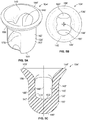
- FIGS. 3A and 3B illustrate front and side cross-sectional views, respectively, of an exemplary embodiment of a first bolster device 102
- the first bolster device 102 can include a body portion 118 that extends between first and second ends 120, 122 along a central axis 124.
- the first bolster device 102 can have a first length or height in a direction that is relatively or generally parallel to the central axis 124 (as indicated by the "L 1 " direction in FIG. 3A ) that is longer than a second length or width of the first bolster device 102 in a direction that is arranged generally perpendicular to the central axis 124 (as indicated by the "L 2 " direction in FIG. 3B ).
- the first bolster device 102 can have a variety of shapes including, for example, rectangular, trapezoidal, oval, or triangular, among other suitable shapes and sizes. As discussed below in greater detail, according to certain embodiments, such a configuration can permit the first bolster device 102 to be manipulated to a first orientation in which the first bolster device 102 can pass through a passageway 126 in one or more bones 128a, 128b ( FIGS. 15A and 15B ) that has a size that is similar or greater than the second length or width of the first bolster device 102, but which is less than the first length of the first bolster device 102.
- the first bolster device 102 Upon removal from the passageway 126, the first bolster device 102 can be placed in a second orientation in which the first bolster device 102 is positioned in a manner that utilizes the larger first length of the first bolster device 102 to prevent re-entry of the first bolster device 102 into the passageway 126.
- the first bolster device 102 includes one or more tether apertures 130a, 130b that extend between the front side 131a and the back side 131b of the first bolster device 102 along an aperture axis 133 that can be arranged generally perpendicular to the central axis 124 of the first bolster device 102.
- the tether apertures 130a, 130b are sized to at least receive one or more passages of portions of the suture(s) 110 of the adjustable tether 106.
- the first bolster device 102 includes a first tether aperture 130a and a second tether aperture 130a, the first and second tether apertures 130a.
- At least a portion of the suture 110 can extend in a first direction generally away from the second bolster device 104 through one of the first and second tether apertures 130a, 130b of the first bolster device 102, and subsequently pass through the other of the first and second tether apertures 130a, 130b in a second, opposite direction generally toward the second bolster device 104.
- Such passages of the suture 110 through the first and second tether apertures 130a, 130b can be repeated one or more times.
- at least a portion of the suture 110 can also be wrapped through the first and second tether apertures 130a.
- the sutures 110 can pass through one of the first and second tether apertures 130a, 130b before returning back toward the second bolster device 104.
- the adjustable tether 106 can comprise separate sutures 110 that each extend through separate ones of the tether apertures 130a, 130b, and which are joined together by the pre-tied slideable locking knot 116.
- the first bolster device 102 can also include one or more lead suture apertures 132 that extend between the front side 131a and the back side 131b of the first bolster device 102 along an aperture axis 136 that can be generally arranged perpendicular to the central axis 124 of the first bolster device 102,
- the lead suture apertures 132 can be sized to at least accommodate the passage of a lead suture 108 ( FIG. 1A ) that can be used in the displacement of the first bolster device 102 through a passageway 126 in one or more bones 128a, 128b, as discussed in greater detail below.
- the first bolster device 102 is depicted as having two lead suture apertures 132.
- the lead suture 108 may extend through only one of the lead suture apertures 132.
- the first bolster device 102 can have only one lead suture aperture 132 through which the lead suture 108 extends.
- the lead suture aperture 132 may, or may not, be configured as an aperture that is separate from the tether apertures 130a. 130b such that lead suture 108 and the suture 110 of the adjustable tether 106 do, or do not, extend through the same aperture.
- 1A and 2 illustrate the lead suture apertures 132 positioned outside of the tether apertures 130a, 130b
- the tether apertures 130a, 130b can be positioned outside of the lead suture apertures 132 such that the tether apertures 130a, 130b are separated from each other by one or more of the lead suture apertures 132.
- FIGS, 4A and 4B illustrate front and top perspective views, respectively, of an exemplary embodiment of a second bolster device 104.
- the second bolster device 104 includes a wall 138 having an inner portion 140, an outer portion 142, a first end 144, and a second end 146.
- the wall 138 extends from the first end 144 to the second end 146 of the wall 138 of the second bolster device 104 along a central axis 148. Further, at least a portion of the wall 138 is configured to provide a generally elongated body portion 150.
- the body portion 150 can have a variety of different shapes and sizes, such as, for example, having an oval, square, rectangular, or other non-circular cross-sectional shapes, among other suitable shapes.
- the body portion 150 is generally cylindrical such that the second bolster device 104 can have a plug shape.
- the body portion 150 can be sized such that at least a portion of the body portion 150 extends into a passageway 126 formed in a bone(s) 128a, 128b and/or through an aperture 152 in a bone plate 154 ( FIGS. 10A and 10B ), as discussed in greater detail below.
- the wall 138 can also include a tapered portion 156 in which the wall 138 outwardly extends from the elongated body portion 150 to a plate portion 158 at the first end 144 of the wall 138.
- the wall 138 can have a size such as, for example, a diameter, along the elongated body portion 150 of the second bolster device 104 that is smaller than a corresponding size, such as a diameter of the plate portion 158 at the first end 144 of the wall 138.
- At least a portion of the outer portion 142 of the wall 138 along the tapered portion 156 and/or plate portion 158 can be sized to prevent the entire second bolster device 104 from being pushed or pulled into the passageway 126 in one or more bones 128a. 128b and/or through an aperture 152 in a bone plate 154.
- at least the plate portion 158 can have a size that abuts against an adjacent portion of bone or an inner wall of an aperture 152 in a bone plate 154 while at least a portion of the body portion 150 extends into the passageway 126 and/or through the aperture in the bone plate 154.
- the second bolster device 104 can be sized to prevent the second bolster device 104, such as the first end of the second bolster device 104, from extending beyond an outer surface 153 of the bone plate 154 when the second bolster device 104 is operably positioned in the aperture 152 of the bone plate 154.
- At least a portion of the elongated body portion 150 can be provided with a shape and/or size that assists in the positioning of at least a portion of the body portion 150 of the second bolster device 104 in the passageway 126 in a bone(s) 128a, 128b and/or through an aperture 152 of a bone plate 154.
- the elongated body portion 150 can decrease in size as the wall 138 approaches the second end 146 of the wall 138 of the second bolster device 104.
- the elongated body portion 150 can taper inwardly and/or have a chamfer or curvature as the wall 138 approaches the second end 146, as shown in at least FIG. 4A .
- the first end 144 of the wall 138 of the second bolster device 104 can include an inlet 145 in communication with a channel 147 that extends within a portion of the second bolster device 104 along the central axis 148.
- the channel 147 can extend from the inlet 145 to an opposite base portion 162 of the channel 147.
- the inlet 145 and the base portion 162 can be separated from each other by a distance that provides the channel 147 with a depth that can accommodate the recessed insertion or embedding of the pre-tied slideable locking knot 116 of the adjustable tether 106 into/in the channel 147, as discussed in greater detail below.
- the depth of the channel 147 can allow the pre-tied slideable locking knot 116 to be placed in the channel 147 in a manner that prevents the pre-tied slideable locking knot 116 from extending beyond the inlet 145, and thereby be recessed or embedded in the channel 147 below at least a portion of the plate portion 158 of the second bolster device 104.
- the second bolster device 104 can include one or more tether openings 164 and/or recesses 166 that are in communication with the channel 147. While certain embodiments the second bolster device 104 illustrated herein are depicted as having two tether openings 164, the number of tether openings 164 can vary, including, but not limited to, having a single tether opening 164 or three or more tether openings 164. According to the embodiment illustrated in FIGS. 4A and 4B . recesses 166 on opposing sides of the wall 138 can generally extend upwardly from the second end 146 of the second bolster device 104 to a tether opening 164 in the body portion 150 of the wall 138.
- the recesses 166 may be positioned so as to extend from at least a portion of the second end 146 of the second bolster device 104 to different or opposing sides of the channel 147. Further, the recesses 166 can extend into the wall 138 at a depth that may permit the adjustable tether 106 to be recessed in the recess 166 such that adjustable tether 106 does not outwardly protrude from the recess 166 beyond the outer portion 142 of the wall 138. Alternatively, the recesses 166 can have a depth to accommodate portions of the adjustable tether being compressed into the recesses 166 when the body portion 150 is positioned in a passageway 126.
- the portion of the adjustable tether 106 positioned along and/or within the recesses 166 can generally be arranged flush with or recessed below adjacent outer portions 142 of the wall 138 so that the recessed portions of the adjustable tether 106 are not in a position that interferes with the placement of at least a portion of the second bolster device 104 in the passageway of a bone 128a, 128b and/or an aperture 152 of a bone plate 154.
- a tether opening 164 can extend through opposing sides of the wall 138 along an axis 168 that is arranged generally perpendicular to the central axis 148 of the second bolster device 104.
- the tether opening 164 may be formed by an intersection of the channel 147 with the recesses 166, and can also define the location of the base portion 162. For example, according to the embodiment shown in FIGS. 4A and 4B .
- the tether opening 164 can be positioned such that one or more sutures 110 of the adjustable tether 106 can extend in a direction that is generally directed away from the first bolster device 102 along one of two recesses 166 in the sidewall 138 before extending across a bridge portion 178 at the base portion 162 of the channel 147, and subsequently extend along the other of the two recesses 166 in the sidewall 138 in a direction that is generally directed toward the first bolster device 102.
- the wall 138 can have a thickness between the base portion 162 of the channel 147 and the second end 146 that can accommodate forces exerted on the bridge portion 178 of the second bolster device 104 by the adjustable tether 106.
- FIGS. 5A-5C illustrate front top, and side cross-sectional views, respectively of an exemplary embodiment of a second bolster device 104'.
- a pair of opposing recesses 166' extend upwardly generally from the second end 146' of the wall 138' to an area at or around the tapered portion 156' of the wall 138'. Additionally, at least a portion of the recesses 166' extend to a depth in the wall 138' that exposes a portion of the channel 147', or otherwise allows the recesses 166' to be positioned in communication with the channel 147'.
- the recesses 166' and/or base portion 162' of the channel 147' can have a rounded or chamfered shape so as to prevent the adjustable tether 106' from transitioning from the recesses 166' to the bridge portion 178 at the base portion 162' along a corner or sharp edge.
- FIGS. 6A-6D illustrate front and top views, respectively, of an exemplary embodiment of a second bolster device 104"
- the plate portion 158" can extend from the body portion 150" in a direction that is arranged generally perpendicular to the channel 147" and/or the body portion 150".
- the plate portion 158" can have an oversized and/or generally elongated shape.
- the plate portion 158" can have a length along a first axis 160 (which is shown as shared by line 6D-6D in FIG.
- the plate portion 158" can have a length along the first axis 160 that is at least about 1 to around 3 times larger, and more particularly about 1.1 to about 1.5 times larger, than the length of the plate portion 158" along a second axis 160.
- the length of the plate portion 158" along the first axis 160 can be approximately 1.27cm (one-half inch 1/2") while the length of the plate portion 158" along a second axis 160 can be approximately 0.95cm (three-eighths of an inch 3/8").
- the elongated shape of the plate portion 158", and moreover the elongated shape of the plate portion 158" along at least the first axis 160, can, in at least certain circumstances, eliminate the need, whether actual or perceived, for the inclusion of a bone plate 154 ( FIG. 8 ). Further, by eliminating the use of a bone plate 154 in at least certain circumstances, the step of drilling holes into bone 128a, 128b and implanting screws into those drilled holes to secure the bone plate 154 to bone 128a can also be eliminated, as well as the associated risks and damage such holes and screws can present to the bone 128a. Further, such an elongated shape can provide a relatively wide area for the plate portion 158" to abut and/or press against the adjacent bone 128a.
- the plate portion 158" of the present design can have a decreased likelihood of breaking through the cortex of the bone 128a.
- the length of the plate portion 158" along the first axis 160 can be around the same or greater than the overall length of the second bolster device 104" along the central axis 148",
- the length of the plate portion 158" along the first axis 160 can be approximately 1.1 to approximately 3 times greater than the overall length of the second bolster device 104" along the central axis 148".
- the length of the plate portion 158" along the first axis 160 can be approximately 1.27cm (one-half inch 1/2"), which can be approximately 1.5 to 2 times larger than the overall length of the second bolster device 104" from a top surface 170 of the plate portion 158" to the second end 146" of the wall 138".
- the plate portion 158" can be curved in at least one direction.
- the location, orientation, degree, and number of curvatures can be based on a variety of different factors, including the ability of at least a portion of the bottom surface 172 of the plate portion 158" to be shaped to generally conform to the shape and/or size of the portion of the bone 128a against which at least a portion of the bottom surface 172 can abut.
- the plate portion 158" including the top and bottom surfaces 170, 172 can be curved between first and second sidewalls 174a, 174b that are on opposite sides of the first axis 160.
- the apex of the curvature can extend around the first axis 160. Further, such a curvature along the bottom surface 172 of the plate portion 158" can, in at least certain embodiments, facilitate the ability of the bottom surface 172 of the plate portion 158" to be positioned in relatively flush contact with a fibular cortex.
- the inlet of the second bolster device 104" can extend through the plate portion 158" such that at least a portion of the adjustable tether 106 can at least initially extend outside of the channel 147" and beyond the plate portion 158" through the inlet 145".
- the plate portion 158" can include a chamfered or inclined inner wall 176 that can facilitate the passage of at least a portion of the adjustable tether 106 such as, for example, the pre-tied slideable locking knot 116 , into the channel 147".
- the body portion 150" of the second bolster device 104" shown in at least FIGS. 6A , 6C and 6D can be configured similar to any of the body portions 150, 150" shown in FIGS. 4A-5C , or can have a variety of other shaped body portions.
- FIGS. 7A-7C illustrate another exemplary embodiment of a second bolster device 104a having one or more retention tabs 105 that outwardly project from the outer portion 142 of the wall 138.
- the retention tabs 105 can have a variety of shapes and sizes.
- the retention tab 105 has a generally planar profile and outwardly extends from the wall 138 in a direction that is arranged perpendicular to the central axis 148, 148', 148" ( FIGS. 4A . 5C and 6C ).
- the retention tab 105 can have a generally round or curved shape.
- the retention tab 105 can have a variety of other shapes or profiles.
- the retention tab 105 is positioned and shaped to engage one or more locking lobes or teeth 200 in an aperture 152 of a bone plate 154 ( FIGS. 8A and 8B ) in a manner that may assist in retaining the second bolster device 104a in locking engagement with the locking teeth 200.
- the retention tab(s) 105 may be sized to engage a side of the locking tooth/teeth 200 that faces toward the bone of the patient.
- the retention tab 105 can be positioned and sized relative to at least the locking teeth 200 such as when the second bolster device 104a is rotated into an aperture of the bone plate 154.
- the retention tab 105 can be rotated to a position below the superior plate surface such that the retention tab 105 is generally positioned between the bone and the adjacent locking tooth/teeth 200.
- the retention tab 105 can be sized to be at displaced through a space or gap between adjacent locking teeth 200 as the second bolster device 104a is rotated relative to the aperture 152 so that the retention tab 105 is positioned beneath at least one locking tooth 200.
- the locking tooth 200 may be positioned to engage with the retention tab 105 in a manner in which the locking tooth/teeth 200 provides an interference or barrier against at least subsequent axial displacement of the second bolster device 104a out of the associated aperture 152.
- Such engagement between the retention tab 105 and the one or more locking lobes or teeth 200 in the aperture 152 of the bone plate 154 can, for example, at least assist in retaining the second bolster device 104a in position relative to at least the bone plate 154, including, for example, in instances where the tension on the fractured bones that is provided by use of the bone plate 154 and associated bone screws changes.
- engagement between the retention tab 105 and the one or more locking lobes or teeth 200 can at least assist in preventing the second bolster device 104a from being displaced away from, or at least partially popping out of, the bone plate 154.
- the retention tab 105 and/or locking tooth/teeth 200 may be positioned such that the retention tab 105 is in pressing engagement with the locking tooth/teeth 200, or another force is asserted between the retention tab 105 and locking tooth/teeth 200 that prevents at least rotational displacement of the second bolster device 104a relative to the bone plate 154.
- the retention tab 105 is positioned at a distance below the plate portion 158 at the first end 144 of the second bolster device 104a at a location in which the tab engages at least a portion of one or more of the locking teeth 200.
- the retention tab 105 can be positioned about 0.015 millimeters (mm) to about 0.020 millimeters (mm) below the proximately adjacent bottom surface of the plate portion 158 of the second bolster device 104a.
- the retention tab 105 can outwardly extend to a distance that is greater than a similar outward distance of other relatively adjacent portions of the plate portion 158.
- the tab portion 105 can outwardly extend approximately 0.09 millimeters (mm) further than the corresponding outward distance of the proximately adjacent portion of the plate portion 158.
- at least one of the retention tabs 105 and the locking tooth/teeth 200 can be configured to be deformed, deflected, or otherwise bent when in a pressed engagement with the other of the retention tab 105 and the locking tooth/teeth 200.
- the retention tab 105 can have a thickness of approximately 0.020 millimeters (mm).
- FIG. 8 illustrates a side view of an exemplary embodiment of a second bolster device 104b having a threaded member 107.
- the threaded member 107 is configured as an external thread structured to engage one or more of the locking teeth 200 of the bone plate 154 in a manner that at least assists in maintaining the second bolster device 104b in locking engagement with the bone plate 154.
- the thread member 107 can engage one or more of the locking teeth 200 of the bone plate 154 in a manner that at least resists removal of the second bolster device 104b from the bone plate 154.
- at least a portion of the previously discussed plate portion 158 can include, or be replaced by, the threaded member 107.
- the threaded member 107 may pass through a gap or space between adjacent locking teeth 200 of the bone plate 154 and proceed to a position in which at least a portion of the threaded member 107 below the superior surface of the bone plate 154 and between at least one locking tooth 200 and the bone. With at least a portion of the threaded member 107 positioned below at least one locking tooth 200. the locking tooth/teeth 200 provides an interference or barrier against at least subsequent axial displacement of the second bolster device 104b out of the associated aperture 152.
- At least a portion of the threaded member 107 and/or locking tooth/teeth 200 may be positioned such that the threaded member 107 is in pressing engagement with the locking tooth/teeth 200, or another force is provided between the threaded member 107 and locking tooth/teeth 200. that prevents at least rotational displacement of the second bolster device 104b relative to the bone plate 154.
- the engagement between the threaded member 107 and the one or more locking lobes or teeth 200 in the aperture 152 can also at least assist in retaining the second bolster device 104b in position relative to at least the bone plate 154 including, for example, in instances in which the tension on the fractured bones that is provided by use of the bone plate 154 and associated bone screws changes.
- engagement between the threaded member 107 and the one or more locking lobes or teeth 200 can at least assist in preventing the second bolster device 104b from being displaced away from, or at least partially popping out of, the bone plate 154.
- the second bolster device 104a, 104b can also include one or more driver surfaces 109 that are shaped to facilitate engagement between the second bolster device 104a, 104b and a driver 300 ( FIGS. 15C and 15D ).
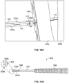
- the driver surfaces 109 can be positioned to form one or more recesses 111 in second bolster device 104a, 104b that can each receive an arm 302a, 302b of the driver 300.
- the arms 302a, 302b of the driver 300 can extend from a shaft 304 that is coupled to a handle 306.
- the arms 302a, 302b can be separated from each other by a gap 308.
- the gap 308 and/or recesses 111 may be sized to accommodate at least a portion of the arms 302a, 302b being received in a corresponding recess 111. Further, the gap 308 can extend along a length of the shaft 304 so as to accommodate at least a portion of the tether 110 of the bolster system 100 being received within the gap while the driver 300 is operably engaged with the second bolster device 104a, 104b.
- a user may rotate the driver 306 such as by gripping the handle 306.
- rotation of the driver 300 will be translated to the second bolster device 104a, 104b via the arms 302a, 302b engaging one or more of the driver surfaces 109.
- rotation of the second bolster device 104a, 104b can, when the second bolster device 104a, 104b is being inserted into an aperture 152 of the bone plate 154 ( FIG.
- While the retention tab 105, the threaded member 107, the driver surfaces 109, and the recesses 111 are discussed and illustrated in connection with certain exemplary second bolster devices 104a, 104b, such features can also be incorporated into other bolster devices including, for example, the second bolster devices 104, 104', 104" illustrated in FIGS. 1A-6D , among other devices. Similarly, the features discussed herein with respect to the second bolster devices 104, 104', 104" illustrated in FIGS. 1A-6D can be incorporated into the second bolster devices 104a, 104b shown in FIGS. 7A-8 , among other devices.
- the second bolster device 104, 104', 104", 104a, 104b can be secured within the bone plate 154 at a variety of different angles while still being recessed within at least the bone plate 154.
- Such variability can provide a degree of patient-to-paticnt variability.
- the second bolster device 104. 104', 104 ", 104a, 104b can have a size and/or shape that can accommodate the second bolster device 104, 104', 104", 104a, 104b having up to 15 degrees of freedom relative to at least the aperture 152 of the bone plate 154.
- the number of locking teeth 200 for an aperture 152 can vary and can include, for example, five or six locking teeth 200, among other numbers of locking teeth 200.
- FIG. 9 illustrates an example of a second bolster device 104" secured to an adjustable tether 106 prior to implantation in a patient.
- the pre-tied slideable locking knot 116 is positioned or embedded within the channel 147" such that the pre-tied slideable locking knot 116 is positioned adjacent to the bridge portion 178 of the second bolster device 104 at the base portion 162 of the channel 147".
- the channel 147" can have one or more sizes such as, for example, a diameter and depth that accommodate placement of the pre-tied slideable locking knot 116 in the channel 147".
- the channel 147" can also have a depth that prevents ends 180 of the adjustable tether 106 that extend from beyond the pre-tied slideable locking knot 116 from extending beyond the inlet 145 of the second bolster device 104, 104', 104" when the bolster system 100 is implanted in a patient. Moreover, at least a portion of the ends 180 of the adjustable tether 106 can be removed or cut when the bolster system 100 is operably positioned or secured to a patient.
- the channel 147" can have a depth that permits the remaining portions of the cut ends 180 that extend from the pre-tied slideable locking knot 116 from extending outside of the channel 147", thereby at least attempting to prevent the ends 180 from engaging the patient in a manner that can result in irritation to the patient.
- FIG, 11 illustrates a drill bit 182 for use with the bolster system 100.
- the drill bit 182 can include a first section 184a and a second section 184b, the first section 184a having a size such as, for example, a diameter that is larger than a corresponding size of the second section 184b.
- the first section 184a can extend from a first end 186 of the drill bit 182 and can include at least the cutting edge and flutes of the drill bit 182.
- the first section 184a of the drill bit 182 can provide the cutting surface and flute for a 3.5 millimeter drill bit.
- the first section 184a can include a first shank portion 188a and the second portion 184b can, include a second shank portion 188b, with the first shank portion 188a having an outer size that is larger than a corresponding outer size of the second shank portion 188b.
- the portion of the second shank portion 188b that is in proximity to the second end 190 of the drill bit 182 can include an eyelet that extends through at least a portion of, or extends from, the second shank portion 188b.
- the eyelet can extend from the second shank portion 188b and have an outer size such as, for example, a diameter which is smaller than a corresponding size of the second shank portion 188b.
- the eyelet is configured to provide an opening through which the lead suture 108 can extend in a manner that can accommodate the lead suture being coupled to the drill bit 182,
- the lead suture 108 can be tied to itself such that the lead suture 108 forms a generally continuous loop that extends through the eyelet, as well as through one or more tether apertures 130a, 130b in the first bolster device 102.
- FIG. 12 illustrates use of an exemplary drill guide 194 to guide the location of drilling by the drill bit 182 through one or more bones 128a, 128b in connection with forming a passageway 126 through the bone(s) 128a, 128b.
- the bone plate 154 prior to drilling of the passageway 126, can be secured to an exterior surface of a bone 128a through the insertion of one or more fixation devices 196, such as screws, through apertures 152 in the bone plate 154 and into drilled holes in the bone 128a.
- the bolster system 100 including at least certain embodiments of the second bolster device 104, 104', 104a, 104b, among others, can be received within an aperture 152 in the bone plate 154.
- the bolster system 100 can be utilized in a patient without the inclusion of a bone plate 154.
- the drill guide 194 can be configured to be used with, or without, a separate drill clamp, and can be positioned along the bone(s) 128a, 128b at a location in which drill bit 182, when operably coupled to the drill guide 194, will drill or otherwise form the passageway 126 along a pre-determined trajectory and/or at pre-determined location within the bone(s) 128a, 128b.
- the drill bit 182 can also be, if not already, coupled to a drill (not shown) such that operation of the drill rotates the drill bit 182 in an manner in which the drill bit 182 can cut into the bone(s) 128a, 128b to form the passageway 126. Referencing FIG. 12 , according to the illustrated embodiment, the drill bit 182 can be operated by operation of the drill to cut through the four cortices of the fibula 128a and tibia 128b.
- the passageway 126 can be provided with a variety of different shapes and/or sizes.
- the passageway 126 can generally have a circular cross-sectional shape that is provided by the drill bit 182.
- the size and/or shape of the passageway 126 can be altered via the use of one or more other cutting or shaping instruments or components.
- FIGS. 13A and 13B illustrate a cutting guide that can be used with at least the drill bit 182b to provide the passageway 126 in the bone 128a, 128b with a non-round cross-sectional shape such as, for example, an oval shape.
- the cutting guide can include a first drill bit 182a ( FIG.
- a second drill bit 182b ( FIG. 13B ) can then be positioned to extend along the slot 198 of the first drill bit 182a as the second drill bit 182b removes additional bone material from the bone(s) 128a, 128b at a location that at least extends from one side of the hole that was formed in the bone(s) 128a, 128b by the first drill bit 182a.
- the combination of holes formed by the first and second drill bits 182a, 182b can thereby form a passageway 126 having a generally elongated and/or oval shape.
- Such non-round shapes can be particularly suited for forming holes which are large enough to accommodate the insertion of at least a portion of the body portion 150, 150', 150" of the second bolster device 104, 104', 104" , but which are also constrained by the size of the aperture 152 of a bone plate 154 such as, for example, at a location between locking teeth 200 in the aperture 152 of the bone plate 154 ( FIGS. 10A and 10B ).
- first and second drill bits 182a, 182b a single drill bit having a short cutting surface and flat surfaces that can fit between the locking teeth 200 in the aperture 152 of the bone plate 154 can be used.
- FIGS. 14A and 14B illustrate another shaping apparatus 202 structured to form a cross-sectional shape and/or size of a passageway through one or more bones 128a, 128b.
- the shaping apparatus 202 includes a drill bit 182" that drills through the cortices of one or more of the bones 128a, 128b.
- the shaping apparatus 202 can further include a chisel 204 that can slide over the drill bit 182" or otherwise be displaced with the drill bit 182", and though the hole formed by the drill bit 182".
- the chisel 204 can pass along or with the drill bit 182" and through the aperture 152 in the bone plate 154.
- the chisel 204 which can have an ovular cross-sectional shape, can be displaced along the drill bit 182" in a direction that is generally tangential to locking teeth 200 in the aperture 152 of the bone plate 154.
- the drill bit 182" can guide displacement of the chisel 204 through the hole formed by the drill bit 182" as the chisel 204 is tapped with an impact device such as, for example, a hammer or another impact device, and thereby forming a generally oval, or non-round, shaped passageway 126.
- an impact device such as, for example, a hammer or another impact device
- the drill bit 182, 182a, 182b, 182" can be decoupled from the drill, thereby exposing the eyelet.
- the lead suture .108 which can already be coupled to the first bolster device 102, can then be coupled to the drill bit 182, 182a, 182b, 182" such that, as the drill bit 182, 182a, 182b, 182" is pulled through the passageway 126, at least a portion of the lead suture 108 can also pass through the passageway 126. Referring to FIG.
- the first bolster device 102 can be oriented, if not already, at a first orientation so that the first bolster device 102 is oriented to pass into a first side 206a of and through the passageway 126.
- the first bolster device 102 can then be displaced through the passageway 126 by a pulling force on the drill bit 182, 182a, 182b, 182, and/or the lead suture 108.
- the first bolster device 102 When the first bolster device 102 passes out of a second side 206b of the passageway 126, the first bolster device 102 can be manipulated to, if not already in, a second orientation that can abut the back side 131b of the first bolster device 102 against a bone 128b in a manner that prevents the return passage of the first bolster device 102 through the passageway, as shown in FIG. 14 .
- the pre-tied slideable locking knot 116 can be formed at least before the lead suture 108 and/or first bolster device 102 enters the passageway 126. Additionally, according to certain embodiments, the pre-tied slideable locking knot 116 can be pre-formed such as that the pre-tied slideable locking knot 116 is, and remains, embedded in the second bolster device 104, 104', 104" including, for example, embedded in the second bolster device 104, 104', 104" prior to the first bolster device 102 entering into the passageway 126.
- one or more ends 180 of the adjustable tether 106 can be pulled so as to at least axially displace the pre-tied slideable locking knot 116 from a first position to a second position so that the bolster system 100 exerts tension on the fibula and tibia in a manner that can at least assist in the repair of the tibiofibular joint.
- the pre-tied slideable locking knot 116 is embedded in the second bolster device 104, 104', 104"
- such displacement of the pre-tied slideable locking knot 116 can be relative to the adjustable tether 106, as the pre-tied slideable locking knot 116 can generally be at a relatively static position relative to the second bolster device 104, 104', 104" and/or subjected to minimal axial displacement generally in a direction the along the central axis 148, 148', 148" within the second bolster device 104, 104', 104"
- the pre-tied slideable locking knot 116 when tightened, can be axially displaced from a first position at which the pre-tied slideable locking knot 116, or a portion of the pre-tied slideable locking knot 116, is positioned outside of the second bolster device 104, 104', 104", to a second position in which the pre-tied slideable locking knot 116 is recessed inside of the second bolster device 104, 104', 104", Additionally, according to certain embodiments, the second bolster device 104.
- the pre-tied slideable locking knot 116 can be positioned or embedded in the channel 147, 147", 147" of the second bolster device 104, 104', 104" at a location in which the pre-tied slideable locking knot 116 abuts against or is otherwise in close proximity to the bridge portion 178 at the base of the channel 147, 147', 147" of the second bolster device 104, 104', 104", Further, the pre-tied slideable locking knot 116 is configured to prevent the pre-tied slideable locking knot 116 from returning from the second position to the first position along the adjustable tether 106 so as to at least assist the bolster system 100 in maintaining tension on fi
- the bolster system 100 can be utilized for repairs to a variety of other joints and/or bones.
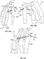
- the bolster system 100 can extend through adjacent metacarpal bones 208a, 208b of a wrist or hand 210.
- a passageway can be drilled or otherwise formed through the first and second metacarpal bones 208a, 208b that is sized to accommodate the passage of a first bolster device 102 when the first bolster device 102 is in a first orientation.
- the adjustable tether 106 can be operably secured to the first device 102 prior to insertion of the first device 102 into the drilled or otherwise formed passageway in the first and second metacarpal bones 208a, 208b.
- the second bolster device 104''' can be operably secured to the adjustable tether 106 by the pre-tied slideable locking knot 116 prior to insertion of the first bolster device 102 into the first and second metacarpal bones 208a, 208b.
- the pre-tied slideable locking knot 116 can be formed such that the pre-tied slideable locking knot 116 is embedded within the second bolster device 102, wherein the pre-tied slideable locking knot 116 can remain at least before, during, and after the first bolster device 102 has been inserted into and through the passageway in the first and second metacarpal bones 208a, 208b, as well as before and during the displacement of the pre-tied slideable locking knot 116 from the first position to the second position relative to at least the adjustable tether 106.
- the first bolster device 102 upon exiting the passageway of the first metacarpal bone 208a, the first bolster device 102 can be manipulated to a second position that prevents the first bolster device 102 from passing back through the passageway.
- the first and/or second ends 112, 114 of the adjustable tether 106 can be pulled, thereby reducing a length of the adjustable tether 106 that extends between at least the pre-tied slideable locking knot 110 and the first bolster device 102, and thereby displacing the slideable locking knot 116 from the first position to the second position relative to at least the adjustable tether 106.
- FIGS. 17A and 17B illustrate an additional, non-limiting use of the bolster system 100 in the repair of joints and/or bones.
- the bolster system 100 can also be used in association with the repair of a shoulder such as, for example, repair of acromioclavicular (AC) joints 212.
- implantation of the bolster system 100 can include passing the first bolster device 102 at a first orientation through a passageway drilled or otherwise formed in the clavicle 214 and the acromion 216.
- first bolster device 102 With the first bolster device 102 extending out of the passageway and beyond the acromion 216, the first bolster device 102 can be manipulated to a second orientation that prevents the first bolster device 102 from passing back through the passageway. While a variety of different shaped and sized first bolster devices 102 can be used with the bolster system 100, according to certain embodiments, relatively small bolster devices 102 may be used such as, for example, bolster devices 102 having a width of about 3.5 millimeters (mm).
- the first and/or second ends 112, 114 of the adjustable tether 106 can be pulled, thereby reducing a length of the adjustable tether 106 that extends between at least the pre-tied slideable locking knot 116 and the first bolster device 102, and thereby displacing the slideable locking knot 116 from the first position to the second position relative to at least the adjustable tether 106 such that pre-tied slideable locking knot 116 is tightened at the second position.
- first and/or second ends 112, 114 of the adjustable tether 106 can be pulled such that the pre-tied slideable locking knot 116 is tightened in a manner that prevents the length of the adjustable tether 106 between the first bolster device 102 arid at least the pre-tied slideable locking knot 116 and/or the second bolster device 104'''' from subsequently increasing.
Landscapes
- Health & Medical Sciences (AREA)
- Orthopedic Medicine & Surgery (AREA)
- Life Sciences & Earth Sciences (AREA)
- Surgery (AREA)
- Medical Informatics (AREA)
- General Health & Medical Sciences (AREA)
- Biomedical Technology (AREA)
- Heart & Thoracic Surgery (AREA)
- Nuclear Medicine, Radiotherapy & Molecular Imaging (AREA)
- Molecular Biology (AREA)
- Animal Behavior & Ethology (AREA)
- Engineering & Computer Science (AREA)
- Public Health (AREA)
- Veterinary Medicine (AREA)
- Neurology (AREA)
- Rheumatology (AREA)
- Dentistry (AREA)
- Oral & Maxillofacial Surgery (AREA)
- Surgical Instruments (AREA)
Description
- Embodiments of the present invention generally relate to joint repair. More particularly, but not exclusively, embodiments of the present invention relate to an adjustable apparatus that at least assists in maintaining tension on a one or more bones during joint repair and/or healing.
- Reconstructive surgery can be utilized to repair damaged and/or unstable sprains, among other injuries. For example, in at least certain instances, reconstructive surgery can be utilized to repair damage to the distal tibiofibular joint, including but not limited to damage associated with certain high ankle sprains and/or breaks and fractures of the fibula and tibia, among repairs to other joints. Such surgeries can seek to establish/re-establish the correct apposition, placement, and/or separation of the fibula relative to the tibia, or vice versa. Further, such reconstructive surgery can also seek to re-establish the integrity of the fibula and tibia, as well as re-establish axial, rotational and transitional forces. A common procedure tor repairing certain types of injuries to the distal tibiofibular joint is syndemosis screw fixation. During syndemosis screw fixation, at least two fixation screws are driven into drilled holes in the bone(s) of a patient. Such screws are typically also driven through holes in a bone plate that abuts, or is generally positioned adjacent to, an outer surface of the patient's bone. Yet, such drilling and screw implantation can cause damage to the bone(s) and/or weaken portions of the bone. Further, after several weeks or months of recovery, such hardware is typically removed from the patient, which typically involves the patient undergoing a subsequent or additional procedure.
EP1016377 discloses a for locking a suture in place comprises an anchor having a front section and a rear section - The present invention provide an apparatus that includes an adjustable tether having a pre-tied knot slideably displaceable in one direction from a first axial position to a second axial position. The apparatus also includes a lead suture and a first bolster device that is coupled to the adjustable tether via one or more tether apertures in the first bolster device, the first bolster device having a width and a length that are each sized to accommodate passage of the first bolster device through a passageway in a first orientation of the first bolster device, and which are sized to prevent passage through the passageway when the first bolster device is in a second orientation. Further, the pre-tied knot is configured to be tied prior to insertion of the first bolster device into the passageway. The first bolster device is coupled to the lead suture via one or more lead suture apertures in the first bolster device. The apparatus also includes a second bolster device coupled to the adjustable tether, the second bolster device being positioned between the pre-tied knot and the first bolster device. The second bolster device includes a channel that extends through at least a portion of the second bolster device, the channel being sized to receive placement of the pre-tied knot, Further, an axial distance between the pre-tied knot and the first bolster device is reduced by slideable displacement of the pre-tied knot from the first axial position to the second axial position.
- Preferred embodiments of the invention are recited in the dependent claims.
- The description herein makes reference to the accompany ing figures wherein like reference numerals refer to like pans throughout the several views.
-
FIG. 1A illustrates a side perspective view of a portion of a bolster system that is coupled to a lead suture. -
FIG. 1B illustrates a side perspective view of a bolster system that is coupled to a lead suture and which includes an adjustable tether having a pre-tied slideable locking knot. -
FIG. 2 illustrates a side perspective view of a bolster system. -
FIGS. 3A and 3B illustrate a front view and a side cross-sectional view, respectively, of an exemplary embodiment of a first bolster device. -
FIGS. 4A and 4B illustrate a front view and top perspective view, respectively, of an exemplary embodiment of a second bolster device. -
FIGS. 5A-5C illustrate a front view, a top view, and a side cross-sectional view, respectively, of an exemplary embodiment of a second bolster device. -
FIGS. 6A and 6B illustrate a front view and top view, respectively, of an exemplary embodiment of a second bolster device. -
FIG. 6C illustrates a cross-sectional view of an embodiment of a second bolster device taken alongline 6C-6C ofFIG. 6B . -
FIG. 6D illustrates a cross-sectional view of an exemplary embodiment of a second bolster device taken alongline 6D-6D ofFIG. 6B . -
FIG. 7A illustrates a side view of an exemplary embodiment of a second bolster device having a retention tab. -
FIGS. 7B and7C illustrate a top view and a bottom view, respectively, of the second bolster device shown inFIG. 7A . -
FIG. 8 illustrates a side view of an exemplary embodiment of a second bolster device having a threaded member. -
FIG. 9 illustrates a side view of a bolster system that includes the second bolster device fromFIGS. 6A and 6B . -
FIGS. 10A and 10B illustrate an outer side perspective view and a rear side view, respectively, of an exemplary bone plate for use with a bolster system of the present invention. -
FIG. 11 illustrates an exemplary drill bit configured for use with a bolster system of the present invention. -
FIG. 12 illustrates use of an exemplary drill guide to guide the location and trajectory of drilling by a drill bit through one or more bones in connection with forming a passageway through the bone(s). -
FIG. 13A illustrates a perspective view of an exemplary first drill bit that can provide a guide for a second drill bit in connection with shaping a cross-sectional shape and/or size of a passageway in one or more bones. -
FIG. 13B illustrates a second drill bit positioned along a slot of the first drill bit ofFIG. 13A as the second drill it is removing bone material in connection with shaping a passageway in one or more bones. -
FIG. 14A illustrates a side perspective view of an exemplary shaping apparatus structured to form a cross-sectional shape and/or size of a passageway in one or more bones. -
FIG. 14B illustrates an example of the shaping apparatus shown inFIG. 14A being inserted into a bone of a patient. -
FIG. 15A illustrates an example of a lead suture that is coupled to a bolster system being pulled through a passageway in one or more bones. -
FIG. 15B illustrates an example of a bolster system that is operably positioned to maintain tension on a tibia and femoral bone in connection with syndemosis joint repair. -
FIG. 15C illustrates a second bolster device engaged with an exemplary driver as the second bolster device is being displaced into engagement with an exemplary bone plate. -
FIG. 15D illustrates a side view of an embodiment of a driver configured for driving engagement with a second bolster device. -
FIGS. 16A and 16B illustrate an anterior view and a posterior view, respectively, of a bolster system operably extending through adjacent metacarpal bones. -
FIG. 16C illustrates a phantom medial view of the bolster system and metacarpal bones shown inFIGS. 16A and 16B . -
FIGS. 17A and 17B illustrate a side view and a phantom side view, respectively, of a bolster system used in connection with repairs to an acromioclavicular joint. - The foregoing summary, as well as the following detailed description of certain embodiments of the present invention, will be better understood when read in conjunction with the appended drawings. For the purpose of illustrating the invention, there is shown in the drawings certain embodiments. It should be understood, however, that the present invention is not limited to the arrangements and instrumentalities shown in the attached drawings.
- Certain terminology is used in the foregoing description for convenience and is not intended to be limiting. Words such as "upper," "lower," "top." "bottom," "first," and "second" designate directions in the drawings to which reference is made. This terminology includes the words specifically noted above, derivatives thereof, and words of similar import. Additionally, the words "a" and "one" are defined as including one or more of the referenced item unless specifically noted. The phrase "at least one of" followed by a list of two or more items, such as "A, B or C," means any individual one of A, B or C, as well as any combination thereof.
-
FIGS. 1A, 1B and2 illustrate side perspective views of at least a portion of a bolstersystem 100 according to an embodiment of the present invention. As illustrated, the bolstersystem 100 can include a first bolsterdevice 102. a second bolsterdevice 104, and anadjustable tether 106.FIGS. 1A, 1B and2 further depict alead suture 108 coupled to the first bolsterdevice 102. The first and second bolsterdevices adjustable tether 106 can comprise a wire, fiber orsuture 110, among other items or devices, that passes around, through, and/or about at least a portion of the first and second bolsterdevices adjustable tether 106 therebetween that is operably coupled to the first and second bolsterdevices FIGS. 1B and2 , the first bolsterdevice 102 can be positioned at afirst end 112 of theadjustable tether 106. while the second bolsterdevice 104 can be positioned at or around a second,opposite end 114 of theadjustable tether 106. - As illustrated in at least
FIG. 1B , and as discussed below in greater detail, theadjustable tether 106 can include a pre-tiedslideable locking knot 116 at or around thesecond end 114 of theadjustable tether 106. Moreover, according to the illustrated embodiment, theslideable locking knot 116 can be positioned at an end of thetether 106 adjacent to the second bolsterdevice 104. The pre-tiedslideable locking knot 116 can be structured for use in adjusting a length of theadjustable tether 106 between the first and second bolsterdevices devices system 100 at least provides tension on a fibula andtibia bones FIG. 15B ). Further, according to certain embodiments, theslideable locking knot 116 can be a one-way locking knot, and more specifically a knot that can shorten, but not expand, at least the distance of the lockingknot 116 from the first bolsterdevice 102 relative to theadjustable tether 106. A variety of different types of knots can be used as the pre-tiedslideable locking knot 116 including, but not limited to, a woven, fast fix, square, and cow hitch knot, among other suitable types and styles of knots. - As illustrated in
FIG. 1B , according to certain embodiments, the pre-tiedslideable locking knot 116 can comprise lockingly intertwined portions of one ormore sutures 110 of theadjustable tether 106 that extend away from the second bolsterdevice 104. Further, according to the illustrated embodiment, the pre-tiedslideable locking knot 116 is formed prior to implantation of at least a portion of the bolstersystem 100 into one or more bones of a patient For example,FIG. 1B provides an indication of the routing of portions of thesuture 110 about itself orother sutures 110 in a manner that can form the pre-tiedslideable locking knot 116 prior to implantation of the bolstersystem 100 into a patient. Additionally, as discussed below, the pre-tiedslideable locking knot 116 can be formed in a manner that allows the pre-tiedslideable locking knot 116 to be displaced along at least a portion of theadjustable tether 106, at least after a portion of the bolstersystem 100 has routed through a passageway in abone system 100 to exert compressive tension against one or more of the patient'sbones - Additionally, according to certain embodiments, the
tether 106 can extend from the second bolsterdevice 106 to first bolsterdevice 102, where a portion of thetether 106 can wrap or extend around a portion of the first bolsterdevice 102, and return to the second bolsterdevice 104, where a portion of thetether 106 can wrap or extend around a portion of the second bolsterdevice 104. According to certain embodiments, this process can be repeated one or more additional times in a manner that accommodates multiple portions or loops of thetether 106 being wound and/or extending between the first and second bolsterdevices tether 106 can extend from the second bolsterdevice 104 such that at least a portion of thetether 106 forms theslideable locking knot 116. -
FIGS. 3A and 3B illustrate front and side cross-sectional views, respectively, of an exemplary embodiment of a first bolsterdevice 102, As illustrated, the first bolsterdevice 102 can include abody portion 118 that extends between first and second ends 120, 122 along acentral axis 124. Further, according to the illustrated embodiment, the first bolsterdevice 102 can have a first length or height in a direction that is relatively or generally parallel to the central axis 124 (as indicated by the "L1" direction inFIG. 3A ) that is longer than a second length or width of the first bolsterdevice 102 in a direction that is arranged generally perpendicular to the central axis 124 (as indicated by the "L2" direction inFIG. 3B ). For example, according to certain embodiments, the first bolsterdevice 102 can have a variety of shapes including, for example, rectangular, trapezoidal, oval, or triangular, among other suitable shapes and sizes. As discussed below in greater detail, according to certain embodiments, such a configuration can permit the first bolsterdevice 102 to be manipulated to a first orientation in which the first bolsterdevice 102 can pass through apassageway 126 in one ormore bones FIGS. 15A and 15B ) that has a size that is similar or greater than the second length or width of the first bolsterdevice 102, but which is less than the first length of the first bolsterdevice 102. Upon removal from thepassageway 126, the first bolsterdevice 102 can be placed in a second orientation in which the first bolsterdevice 102 is positioned in a manner that utilizes the larger first length of the first bolsterdevice 102 to prevent re-entry of the first bolsterdevice 102 into thepassageway 126. - According to the illustrated embodiment, the first bolster
device 102 includes one ormore tether apertures front side 131a and theback side 131b of the first bolsterdevice 102 along anaperture axis 133 that can be arranged generally perpendicular to thecentral axis 124 of the first bolsterdevice 102. Thetether apertures adjustable tether 106. For example, according to the illustrated embodiment, the first bolsterdevice 102 includes afirst tether aperture 130a and asecond tether aperture 130a, the first andsecond tether apertures 130a. 130b being separated from one another by abridge portion 134 of the first bolsterdevice 102. According to such embodiment, at least a portion of thesuture 110 can extend in a first direction generally away from the second bolsterdevice 104 through one of the first andsecond tether apertures device 102, and subsequently pass through the other of the first andsecond tether apertures device 104. Such passages of thesuture 110 through the first andsecond tether apertures suture 110 can also be wrapped through the first andsecond tether apertures 130a. 130b and around thebridge portion 134 of the first bolsterdevice 102. Alternatively, according to other embodiments, thesutures 110 can pass through one of the first andsecond tether apertures device 104. Further, according to certain embodiments, theadjustable tether 106 can compriseseparate sutures 110 that each extend through separate ones of thetether apertures slideable locking knot 116. - According to certain embodiments, the first bolster
device 102 can also include one or morelead suture apertures 132 that extend between thefront side 131a and theback side 131b of the first bolsterdevice 102 along anaperture axis 136 that can be generally arranged perpendicular to thecentral axis 124 of the first bolsterdevice 102, Thelead suture apertures 132 can be sized to at least accommodate the passage of a lead suture 108 (FIG. 1A ) that can be used in the displacement of the first bolsterdevice 102 through apassageway 126 in one ormore bones device 102 is depicted as having twolead suture apertures 132. However, according to certain embodiments, thelead suture 108 may extend through only one of thelead suture apertures 132. Additionally, according to certain embodiments, the first bolsterdevice 102 can have only onelead suture aperture 132 through which thelead suture 108 extends. Further, thelead suture aperture 132 may, or may not, be configured as an aperture that is separate from thetether apertures 130a. 130b such thatlead suture 108 and thesuture 110 of theadjustable tether 106 do, or do not, extend through the same aperture. Further, whileFIGS. 1A and2 illustrate thelead suture apertures 132 positioned outside of thetether apertures tether apertures lead suture apertures 132 such that thetether apertures lead suture apertures 132. -
FIGS, 4A and 4B illustrate front and top perspective views, respectively, of an exemplary embodiment of a second bolsterdevice 104. According to the depicted embodiment, the second bolsterdevice 104 includes awall 138 having aninner portion 140, anouter portion 142, afirst end 144, and asecond end 146. According to certain embodiments, thewall 138 extends from thefirst end 144 to thesecond end 146 of thewall 138 of the second bolsterdevice 104 along acentral axis 148. Further, at least a portion of thewall 138 is configured to provide a generallyelongated body portion 150. Thebody portion 150 can have a variety of different shapes and sizes, such as, for example, having an oval, square, rectangular, or other non-circular cross-sectional shapes, among other suitable shapes. According to the illustrated embodiment, thebody portion 150 is generally cylindrical such that the second bolsterdevice 104 can have a plug shape. Further, thebody portion 150 can be sized such that at least a portion of thebody portion 150 extends into apassageway 126 formed in a bone(s) 128a, 128b and/or through anaperture 152 in a bone plate 154 (FIGS. 10A and 10B ), as discussed in greater detail below. - According to certain embodiments, the
wall 138 can also include a taperedportion 156 in which thewall 138 outwardly extends from theelongated body portion 150 to aplate portion 158 at thefirst end 144 of thewall 138. For example, in the illustrated embodiment, thewall 138 can have a size such as, for example, a diameter, along theelongated body portion 150 of the second bolsterdevice 104 that is smaller than a corresponding size, such as a diameter of theplate portion 158 at thefirst end 144 of thewall 138. According to certain embodiments, at least a portion of theouter portion 142 of thewall 138 along the taperedportion 156 and/orplate portion 158 can be sized to prevent the entire second bolsterdevice 104 from being pushed or pulled into thepassageway 126 in one ormore bones 128a. 128b and/or through anaperture 152 in abone plate 154. For example, at least theplate portion 158 can have a size that abuts against an adjacent portion of bone or an inner wall of anaperture 152 in abone plate 154 while at least a portion of thebody portion 150 extends into thepassageway 126 and/or through the aperture in thebone plate 154. Further, the second bolsterdevice 104 can be sized to prevent the second bolsterdevice 104, such as the first end of the second bolsterdevice 104, from extending beyond anouter surface 153 of thebone plate 154 when the second bolsterdevice 104 is operably positioned in theaperture 152 of thebone plate 154. - Additionally, according to certain embodiments, at least a portion of the
elongated body portion 150 can be provided with a shape and/or size that assists in the positioning of at least a portion of thebody portion 150 of the second bolsterdevice 104 in thepassageway 126 in a bone(s) 128a, 128b and/or through anaperture 152 of abone plate 154. For example, as shown in at leastFIG. 4A , according to certain embodiments, theelongated body portion 150 can decrease in size as thewall 138 approaches thesecond end 146 of thewall 138 of the second bolsterdevice 104. For example, according to certain embodiments, theelongated body portion 150 can taper inwardly and/or have a chamfer or curvature as thewall 138 approaches thesecond end 146, as shown in at leastFIG. 4A . - The
first end 144 of thewall 138 of the second bolsterdevice 104 can include aninlet 145 in communication with achannel 147 that extends within a portion of the second bolsterdevice 104 along thecentral axis 148. For example, according to certain embodiments, thechannel 147 can extend from theinlet 145 to anopposite base portion 162 of thechannel 147. Further, theinlet 145 and thebase portion 162 can be separated from each other by a distance that provides thechannel 147 with a depth that can accommodate the recessed insertion or embedding of the pre-tiedslideable locking knot 116 of theadjustable tether 106 into/in thechannel 147, as discussed in greater detail below. More specifically, the depth of thechannel 147 can allow the pre-tiedslideable locking knot 116 to be placed in thechannel 147 in a manner that prevents the pre-tiedslideable locking knot 116 from extending beyond theinlet 145, and thereby be recessed or embedded in thechannel 147 below at least a portion of theplate portion 158 of the second bolsterdevice 104. - According to certain embodiments, the second bolster
device 104 can include one ormore tether openings 164 and/orrecesses 166 that are in communication with thechannel 147. While certain embodiments the second bolsterdevice 104 illustrated herein are depicted as having twotether openings 164, the number oftether openings 164 can vary, including, but not limited to, having asingle tether opening 164 or three ormore tether openings 164. According to the embodiment illustrated inFIGS. 4A and 4B . recesses 166 on opposing sides of thewall 138 can generally extend upwardly from thesecond end 146 of the second bolsterdevice 104 to atether opening 164 in thebody portion 150 of thewall 138. Moreover, therecesses 166 may be positioned so as to extend from at least a portion of thesecond end 146 of the second bolsterdevice 104 to different or opposing sides of thechannel 147. Further, therecesses 166 can extend into thewall 138 at a depth that may permit theadjustable tether 106 to be recessed in therecess 166 such thatadjustable tether 106 does not outwardly protrude from therecess 166 beyond theouter portion 142 of thewall 138. Alternatively, therecesses 166 can have a depth to accommodate portions of the adjustable tether being compressed into therecesses 166 when thebody portion 150 is positioned in apassageway 126. Thus, according to certain embodiments, at least when the bolstersystem 100 is operably implanted in a patient, the portion of theadjustable tether 106 positioned along and/or within therecesses 166 can generally be arranged flush with or recessed below adjacentouter portions 142 of thewall 138 so that the recessed portions of theadjustable tether 106 are not in a position that interferes with the placement of at least a portion of the second bolsterdevice 104 in the passageway of abone aperture 152 of abone plate 154. - According to the illustrated embodiment, a
tether opening 164 can extend through opposing sides of thewall 138 along an axis 168 that is arranged generally perpendicular to thecentral axis 148 of the second bolsterdevice 104. According to certain embodiments, thetether opening 164 may be formed by an intersection of thechannel 147 with therecesses 166, and can also define the location of thebase portion 162. For example, according to the embodiment shown inFIGS. 4A and 4B . thetether opening 164 can be positioned such that one ormore sutures 110 of theadjustable tether 106 can extend in a direction that is generally directed away from the first bolsterdevice 102 along one of tworecesses 166 in thesidewall 138 before extending across abridge portion 178 at thebase portion 162 of thechannel 147, and subsequently extend along the other of the tworecesses 166 in thesidewall 138 in a direction that is generally directed toward the first bolsterdevice 102. Thus, according to such an embodiment thewall 138 can have a thickness between thebase portion 162 of thechannel 147 and thesecond end 146 that can accommodate forces exerted on thebridge portion 178 of the second bolsterdevice 104 by theadjustable tether 106. -
FIGS. 5A-5C illustrate front top, and side cross-sectional views, respectively of an exemplary embodiment of a second bolster device 104'. As illustrated inFIGS. 5A-5C , according to the illustrated embodiment, a pair of opposing recesses 166' extend upwardly generally from the second end 146' of the wall 138' to an area at or around the tapered portion 156' of the wall 138'. Additionally, at least a portion of the recesses 166' extend to a depth in the wall 138' that exposes a portion of thechannel 147', or otherwise allows the recesses 166' to be positioned in communication with thechannel 147'. Further, the recesses 166' and/or base portion 162' of thechannel 147' can have a rounded or chamfered shape so as to prevent the adjustable tether 106' from transitioning from the recesses 166' to thebridge portion 178 at the base portion 162' along a corner or sharp edge. -
FIGS. 6A-6D illustrate front and top views, respectively, of an exemplary embodiment of a second bolsterdevice 104", As illustrated inFIGS. 6A - 6C , theplate portion 158" can extend from thebody portion 150" in a direction that is arranged generally perpendicular to thechannel 147" and/or thebody portion 150". Further, theplate portion 158" can have an oversized and/or generally elongated shape. For example, according to certain embodiments, theplate portion 158" can have a length along a first axis 160 (which is shown as shared byline 6D-6D inFIG. 6B ) of theplate portion 158" arranged generally perpendicular to thecentral axis 148" that is at least equal to, if not longer, than a length or width along a second axis 160 (which is shown as shared byline 6C-6C inFIG. 6B ) that extends in a direction arranged generally perpendicular to thefirst axis 160. For example, according to certain embodiments, theplate portion 158" can have a length along thefirst axis 160 that is at least about 1 to around 3 times larger, and more particularly about 1.1 to about 1.5 times larger, than the length of theplate portion 158" along asecond axis 160. Additionally, according to certain embodiments, the length of theplate portion 158" along thefirst axis 160 can be approximately 1.27cm (one-half inch 1/2") while the length of theplate portion 158" along asecond axis 160 can be approximately 0.95cm (three-eighths of an inch 3/8"). - The elongated shape of the
plate portion 158", and moreover the elongated shape of theplate portion 158" along at least thefirst axis 160, can, in at least certain circumstances, eliminate the need, whether actual or perceived, for the inclusion of a bone plate 154 (FIG. 8 ). Further, by eliminating the use of abone plate 154 in at least certain circumstances, the step of drilling holes intobone bone plate 154 tobone 128a can also be eliminated, as well as the associated risks and damage such holes and screws can present to thebone 128a. Further, such an elongated shape can provide a relatively wide area for theplate portion 158" to abut and/or press against theadjacent bone 128a. Moreover, by providing a large area in which theplate portion 158" abuts against thebone 128a, forces exerted onto thebone 128a by theplate portion 158" can be distributed over a larger area, By distributing the forces exerted onto thebone 128a by theplate portion 158" over a larger area, theplate portion 158" of the present design can have a decreased likelihood of breaking through the cortex of thebone 128a. - According to the embodiment depicted in
FIGS. 6A-6D , the length of theplate portion 158" along thefirst axis 160 can be around the same or greater than the overall length of the second bolsterdevice 104" along thecentral axis 148", For example, according to certain embodiments, the length of theplate portion 158" along thefirst axis 160 can be approximately 1.1 to approximately 3 times greater than the overall length of the second bolsterdevice 104" along thecentral axis 148". As another example, the length of theplate portion 158" along thefirst axis 160 can be approximately 1.27cm (one-half inch 1/2"), which can be approximately 1.5 to 2 times larger than the overall length of the second bolsterdevice 104" from atop surface 170 of theplate portion 158" to thesecond end 146" of thewall 138". - According to certain embodiments, the
plate portion 158" can be curved in at least one direction. The location, orientation, degree, and number of curvatures can be based on a variety of different factors, including the ability of at least a portion of thebottom surface 172 of theplate portion 158" to be shaped to generally conform to the shape and/or size of the portion of thebone 128a against which at least a portion of thebottom surface 172 can abut. For example, according to the illustrated embodiment, theplate portion 158", including the top andbottom surfaces first axis 160. According to such an embodiment, the apex of the curvature can extend around thefirst axis 160. Further, such a curvature along thebottom surface 172 of theplate portion 158" can, in at least certain embodiments, facilitate the ability of thebottom surface 172 of theplate portion 158" to be positioned in relatively flush contact with a fibular cortex. - The inlet of the second bolster
device 104" can extend through theplate portion 158" such that at least a portion of theadjustable tether 106 can at least initially extend outside of thechannel 147" and beyond theplate portion 158" through theinlet 145". Further, in the illustrated embodiment, theplate portion 158" can include a chamfered or inclinedinner wall 176 that can facilitate the passage of at least a portion of theadjustable tether 106 such as, for example, the pre-tiedslideable locking knot 116 , into thechannel 147". Further, thebody portion 150" of the second bolsterdevice 104" shown in at leastFIGS. 6A ,6C and 6D can be configured similar to any of thebody portions FIGS. 4A-5C , or can have a variety of other shaped body portions. -
FIGS. 7A-7C illustrate another exemplary embodiment of a second bolsterdevice 104a having one ormore retention tabs 105 that outwardly project from theouter portion 142 of thewall 138. Theretention tabs 105 can have a variety of shapes and sizes. For example, according to the illustrated embodiment, as shown inFIG. 7A , theretention tab 105 has a generally planar profile and outwardly extends from thewall 138 in a direction that is arranged perpendicular to thecentral axis FIGS. 4A .5C and6C ). Further, as shown inFIGS. 7B and7C , according to certain embodiments, theretention tab 105 can have a generally round or curved shape. However, it should be understood that theretention tab 105 can have a variety of other shapes or profiles. - The
retention tab 105 is positioned and shaped to engage one or more locking lobes orteeth 200 in anaperture 152 of a bone plate 154 (FIGS. 8A and 8B ) in a manner that may assist in retaining the second bolsterdevice 104a in locking engagement with the lockingteeth 200. For example, according to certain embodiments, the retention tab(s) 105 may be sized to engage a side of the locking tooth/teeth 200 that faces toward the bone of the patient. Moreover, theretention tab 105 can be positioned and sized relative to at least the lockingteeth 200 such as when the second bolsterdevice 104a is rotated into an aperture of thebone plate 154. theretention tab 105 can be rotated to a position below the superior plate surface such that theretention tab 105 is generally positioned between the bone and the adjacent locking tooth/teeth 200. For example, according to certain embodiments, theretention tab 105 can be sized to be at displaced through a space or gap between adjacent lockingteeth 200 as the second bolsterdevice 104a is rotated relative to theaperture 152 so that theretention tab 105 is positioned beneath at least onelocking tooth 200. - With the
retention tab 105 at such a position, the lockingtooth 200 may be positioned to engage with theretention tab 105 in a manner in which the locking tooth/teeth 200 provides an interference or barrier against at least subsequent axial displacement of the second bolsterdevice 104a out of the associatedaperture 152. Such engagement between theretention tab 105 and the one or more locking lobes orteeth 200 in theaperture 152 of thebone plate 154 can, for example, at least assist in retaining the second bolsterdevice 104a in position relative to at least thebone plate 154, including, for example, in instances where the tension on the fractured bones that is provided by use of thebone plate 154 and associated bone screws changes. For example, in at least certain instances in which tension used to hold a position of bones or fractures is reduced, engagement between theretention tab 105 and the one or more locking lobes orteeth 200 can at least assist in preventing the second bolsterdevice 104a from being displaced away from, or at least partially popping out of, thebone plate 154. Additionally, theretention tab 105 and/or locking tooth/teeth 200 may be positioned such that theretention tab 105 is in pressing engagement with the locking tooth/teeth 200, or another force is asserted between theretention tab 105 and locking tooth/teeth 200 that prevents at least rotational displacement of the second bolsterdevice 104a relative to thebone plate 154. For example, according to the embodiment illustrated inFIGS. 7A-7C , theretention tab 105 is positioned at a distance below theplate portion 158 at thefirst end 144 of the second bolsterdevice 104a at a location in which the tab engages at least a portion of one or more of the lockingteeth 200. For example, theretention tab 105 can be positioned about 0.015 millimeters (mm) to about 0.020 millimeters (mm) below the proximately adjacent bottom surface of theplate portion 158 of the second bolsterdevice 104a. - Additionally, the
retention tab 105 can outwardly extend to a distance that is greater than a similar outward distance of other relatively adjacent portions of theplate portion 158. For example, according to certain embodiments, thetab portion 105 can outwardly extend approximately 0.09 millimeters (mm) further than the corresponding outward distance of the proximately adjacent portion of theplate portion 158. Further, to at least facilitate such locking engagement, at least one of theretention tabs 105 and the locking tooth/teeth 200 can be configured to be deformed, deflected, or otherwise bent when in a pressed engagement with the other of theretention tab 105 and the locking tooth/teeth 200. For example, according to certain embodiments, theretention tab 105 can have a thickness of approximately 0.020 millimeters (mm). -
FIG. 8 illustrates a side view of an exemplary embodiment of a second bolsterdevice 104b having a threadedmember 107. According to the illustrated embodiment, the threadedmember 107 is configured as an external thread structured to engage one or more of the lockingteeth 200 of thebone plate 154 in a manner that at least assists in maintaining the second bolsterdevice 104b in locking engagement with thebone plate 154. Moreover, thethread member 107 can engage one or more of the lockingteeth 200 of thebone plate 154 in a manner that at least resists removal of the second bolsterdevice 104b from thebone plate 154. For example, according to the illustrated embodiment, at least a portion of the previously discussedplate portion 158 can include, or be replaced by, the threadedmember 107. As the second bolsterdevice 104b is rotated within theaperture 152 of thebone plate 154 and axially displaced toward the bone, at least a portion of the threadedmember 107 may pass through a gap or space between adjacent lockingteeth 200 of thebone plate 154 and proceed to a position in which at least a portion of the threadedmember 107 below the superior surface of thebone plate 154 and between at least onelocking tooth 200 and the bone. With at least a portion of the threadedmember 107 positioned below at least onelocking tooth 200. the locking tooth/teeth 200 provides an interference or barrier against at least subsequent axial displacement of the second bolsterdevice 104b out of the associatedaperture 152. Additionally, at least a portion of the threadedmember 107 and/or locking tooth/teeth 200 may be positioned such that the threadedmember 107 is in pressing engagement with the locking tooth/teeth 200, or another force is provided between the threadedmember 107 and locking tooth/teeth 200. that prevents at least rotational displacement of the second bolsterdevice 104b relative to thebone plate 154. - Additionally, similar to the engagement between the
retention tab 105 and the one or more locking lobes orteeth 200 in theaperture 152 of thebone plate 154, the engagement between the threadedmember 107 and the one or more locking lobes orteeth 200 in theaperture 152 can also at least assist in retaining the second bolsterdevice 104b in position relative to at least thebone plate 154 including, for example, in instances in which the tension on the fractured bones that is provided by use of thebone plate 154 and associated bone screws changes. For example, engagement between the threadedmember 107 and the one or more locking lobes orteeth 200 can at least assist in preventing the second bolsterdevice 104b from being displaced away from, or at least partially popping out of, thebone plate 154. - As shown in
FIGS. 7A-8 , according to certain embodiments, the second bolsterdevice device FIGS. 15C and 15D ). For example, according to the illustrated embodiments, the driver surfaces 109 can be positioned to form one ormore recesses 111 in second bolsterdevice arm driver 300. According to the exemplary embodiment shown inFIGS. 15C and 15D . thearms driver 300 can extend from ashaft 304 that is coupled to ahandle 306. Thearms gap 308. Thegap 308 and/or recesses 111 may be sized to accommodate at least a portion of thearms corresponding recess 111. Further, thegap 308 can extend along a length of theshaft 304 so as to accommodate at least a portion of thetether 110 of the bolstersystem 100 being received within the gap while thedriver 300 is operably engaged with the second bolsterdevice driver 300 is operably engaged with the second bolsterdevice arms recess 111 of the second bolsterdevice driver 306 such as by gripping thehandle 306. Depending on the direction of rotation, such rotation of thedriver 300 will be translated to the second bolsterdevice arms device device aperture 152 of the bone plate 154 (FIG. 15C ), facilitate theretention tab 105 or threadedmember 107 being rotated to a position in which theretention tab 105 or threadedmember 107 is positioned between one ormore locking teeth 200 and anadjacent bone 128a, thereby at least assisting in locking the position of the second bolsterdevice bone plate 154, as discussed in detail above. - While the
retention tab 105, the threadedmember 107, the driver surfaces 109, and therecesses 111 are discussed and illustrated in connection with certain exemplary second bolsterdevices devices FIGS. 1A-6D , among other devices. Similarly, the features discussed herein with respect to the second bolsterdevices FIGS. 1A-6D can be incorporated into the second bolsterdevices FIGS. 7A-8 , among other devices. - Additionally, the second bolster
device bone plate 154 at a variety of different angles while still being recessed within at least thebone plate 154. Such variability can provide a degree of patient-to-paticnt variability. For example, according to certain embodiments, the second bolsterdevice 104. 104', 104 ", 104a, 104b can have a size and/or shape that can accommodate the second bolsterdevice aperture 152 of thebone plate 154. Further, the number of lockingteeth 200 for anaperture 152 can vary and can include, for example, five or six lockingteeth 200, among other numbers of lockingteeth 200. -
FIG. 9 illustrates an example of a second bolsterdevice 104" secured to anadjustable tether 106 prior to implantation in a patient. As shown, the pre-tiedslideable locking knot 116 is positioned or embedded within thechannel 147" such that the pre-tiedslideable locking knot 116 is positioned adjacent to thebridge portion 178 of the second bolsterdevice 104 at thebase portion 162 of thechannel 147". Accordingly, as previously discussed, thechannel 147" can have one or more sizes such as, for example, a diameter and depth that accommodate placement of the pre-tiedslideable locking knot 116 in thechannel 147". Additionally, thechannel 147" can also have a depth that prevents ends 180 of theadjustable tether 106 that extend from beyond the pre-tiedslideable locking knot 116 from extending beyond theinlet 145 of the second bolsterdevice system 100 is implanted in a patient. Moreover, at least a portion of theends 180 of theadjustable tether 106 can be removed or cut when the bolstersystem 100 is operably positioned or secured to a patient.
Thus, thechannel 147" can have a depth that permits the remaining portions of the cut ends 180 that extend from the pre-tiedslideable locking knot 116 from extending outside of thechannel 147", thereby at least attempting to prevent theends 180 from engaging the patient in a manner that can result in irritation to the patient. -
FIG, 11 illustrates adrill bit 182 for use with the bolstersystem 100. According to certain embodiments, thedrill bit 182 can include afirst section 184a and asecond section 184b, thefirst section 184a having a size such as, for example, a diameter that is larger than a corresponding size of thesecond section 184b. According to the illustrated embodiment, thefirst section 184a can extend from afirst end 186 of thedrill bit 182 and can include at least the cutting edge and flutes of thedrill bit 182. For example, according to certain embodiments, thefirst section 184a of thedrill bit 182 can provide the cutting surface and flute for a 3.5 millimeter drill bit. Further, according to certain embodiments, thefirst section 184a can include afirst shank portion 188a and thesecond portion 184b can, include asecond shank portion 188b, with thefirst shank portion 188a having an outer size that is larger than a corresponding outer size of thesecond shank portion 188b. The portion of thesecond shank portion 188b that is in proximity to thesecond end 190 of thedrill bit 182 can include an eyelet that extends through at least a portion of, or extends from, thesecond shank portion 188b. For example, the eyelet can extend from thesecond shank portion 188b and have an outer size such as, for example, a diameter which is smaller than a corresponding size of thesecond shank portion 188b. The eyelet is configured to provide an opening through which thelead suture 108 can extend in a manner that can accommodate the lead suture being coupled to thedrill bit 182, For example, thelead suture 108 can be tied to itself such that thelead suture 108 forms a generally continuous loop that extends through the eyelet, as well as through one ormore tether apertures device 102. -
FIG. 12 illustrates use of anexemplary drill guide 194 to guide the location of drilling by thedrill bit 182 through one ormore bones passageway 126 through the bone(s) 128a, 128b. According to the illustrated embodiment, prior to drilling of thepassageway 126, the bone plate 154 (shown inFIGS. 10A and 10B ) can be secured to an exterior surface of abone 128a through the insertion of one ormore fixation devices 196, such as screws, throughapertures 152 in thebone plate 154 and into drilled holes in thebone 128a. According to such embodiment, as previously discussed, the bolstersystem 100, including at least certain embodiments of the second bolsterdevice aperture 152 in thebone plate 154. However, according to other embodiments, the bolstersystem 100 can be utilized in a patient without the inclusion of abone plate 154. - The
drill guide 194 can be configured to be used with, or without, a separate drill clamp, and can be positioned along the bone(s) 128a, 128b at a location in whichdrill bit 182, when operably coupled to thedrill guide 194, will drill or otherwise form thepassageway 126 along a pre-determined trajectory and/or at pre-determined location within the bone(s) 128a, 128b. Thedrill bit 182 can also be, if not already, coupled to a drill (not shown) such that operation of the drill rotates thedrill bit 182 in an manner in which thedrill bit 182 can cut into the bone(s) 128a, 128b to form thepassageway 126. ReferencingFIG. 12 , according to the illustrated embodiment, thedrill bit 182 can be operated by operation of the drill to cut through the four cortices of thefibula 128a andtibia 128b. - The
passageway 126 can be provided with a variety of different shapes and/or sizes. For example, according to certain embodiments, thepassageway 126 can generally have a circular cross-sectional shape that is provided by thedrill bit 182. According to other embodiments, the size and/or shape of thepassageway 126 can be altered via the use of one or more other cutting or shaping instruments or components. For example,FIGS. 13A and 13B illustrate a cutting guide that can be used with at least thedrill bit 182b to provide thepassageway 126 in thebone first drill bit 182a (FIG. 13A ) that has avertical slot 198 and which is used to drill a first hole in thebone second drill bit 182b (FIG. 13B ) can then be positioned to extend along theslot 198 of thefirst drill bit 182a as thesecond drill bit 182b removes additional bone material from the bone(s) 128a, 128b at a location that at least extends from one side of the hole that was formed in the bone(s) 128a, 128b by thefirst drill bit 182a. The combination of holes formed by the first andsecond drill bits passageway 126 having a generally elongated and/or oval shape. Such non-round shapes can be particularly suited for forming holes which are large enough to accommodate the insertion of at least a portion of thebody portion device aperture 152 of abone plate 154 such as, for example, at a location between lockingteeth 200 in theaperture 152 of the bone plate 154 (FIGS. 10A and 10B ). Alternatively, rather than utilizing first andsecond drill bits teeth 200 in theaperture 152 of thebone plate 154 can be used. -
FIGS. 14A and 14B illustrate anothershaping apparatus 202 structured to form a cross-sectional shape and/or size of a passageway through one ormore bones shaping apparatus 202 includes adrill bit 182" that drills through the cortices of one or more of thebones shaping apparatus 202 can further include achisel 204 that can slide over thedrill bit 182" or otherwise be displaced with thedrill bit 182", and though the hole formed by thedrill bit 182". According to such an embodiment, after thedrill bit 182" has established a hole through thebones chisel 204 can pass along or with thedrill bit 182" and through theaperture 152 in thebone plate 154. For example, according to certain embodiments, thechisel 204, which can have an ovular cross-sectional shape, can be displaced along thedrill bit 182" in a direction that is generally tangential to lockingteeth 200 in theaperture 152 of thebone plate 154. According to such an embodiment, thedrill bit 182" can guide displacement of thechisel 204 through the hole formed by thedrill bit 182" as thechisel 204 is tapped with an impact device such as, for example, a hammer or another impact device, and thereby forming a generally oval, or non-round, shapedpassageway 126. - With the passageway formed, the
drill bit device 102, can then be coupled to thedrill bit drill bit passageway 126, at least a portion of thelead suture 108 can also pass through thepassageway 126. Referring toFIG. 13 , with thelead suture 108 exposed through one side of thepassageway 126, the first bolsterdevice 102 can be oriented, if not already, at a first orientation so that the first bolsterdevice 102 is oriented to pass into afirst side 206a of and through thepassageway 126. The first bolsterdevice 102 can then be displaced through thepassageway 126 by a pulling force on thedrill bit lead suture 108. When the first bolsterdevice 102 passes out of asecond side 206b of thepassageway 126, the first bolsterdevice 102 can be manipulated to, if not already in, a second orientation that can abut theback side 131b of the first bolsterdevice 102 against abone 128b in a manner that prevents the return passage of the first bolsterdevice 102 through the passageway, as shown inFIG. 14 . - As previously mentioned, according to certain embodiments, the pre-tied
slideable locking knot 116 can be formed at least before thelead suture 108 and/or first bolsterdevice 102 enters thepassageway 126. Additionally, according to certain embodiments, the pre-tiedslideable locking knot 116 can be pre-formed such as that the pre-tiedslideable locking knot 116 is, and remains, embedded in the second bolsterdevice device device 102 entering into thepassageway 126. Thus, when the first bolsterdevice 102 is positioned and oriented for operable abutment against a portion of theadjacent bone 128b, one or more ends 180 of theadjustable tether 106 can be pulled so as to at least axially displace the pre-tiedslideable locking knot 116 from a first position to a second position so that the bolstersystem 100 exerts tension on the fibula and tibia in a manner that can at least assist in the repair of the tibiofibular joint. Further, according to certain embodiments in which the pre-tiedslideable locking knot 116 is embedded in the second bolsterdevice slideable locking knot 116 can be relative to theadjustable tether 106, as the pre-tiedslideable locking knot 116 can generally be at a relatively static position relative to the second bolsterdevice central axis device - Alternatively, according to certain embodiments, when tightened, the pre-tied
slideable locking knot 116 can be axially displaced from a first position at which the pre-tiedslideable locking knot 116, or a portion of the pre-tiedslideable locking knot 116, is positioned outside of the second bolsterdevice slideable locking knot 116 is recessed inside of the second bolsterdevice device 104. 104', 104" can be positioned such that at least a portion of the second bolsterdevice passageway 126 and/oraperture 152 of thebone plate 154 prior to displacement of the pre-tiedslideable locking knot 116 from the first position to the second position Further, when at the second position, the pre-tiedslideable locking knot 116 can be positioned or embedded in thechannel device slideable locking knot 116 abuts against or is otherwise in close proximity to thebridge portion 178 at the base of thechannel device slideable locking knot 116 is configured to prevent the pre-tiedslideable locking knot 116 from returning from the second position to the first position along theadjustable tether 106 so as to at least assist the bolstersystem 100 in maintaining tension on fibula and tibia. - While the preceding examples and figures are discussed with respect to syndemosis repairs, it should be understood that the bolster
system 100 can be utilized for repairs to a variety of other joints and/or bones. For example, as illustrated byFIGS. 16A-16C , the bolstersystem 100 can extend through adjacentmetacarpal bones hand 210. According to the illustrated example, a passageway can be drilled or otherwise formed through the first and secondmetacarpal bones device 102 when the first bolsterdevice 102 is in a first orientation. Again, theadjustable tether 106 can be operably secured to thefirst device 102 prior to insertion of thefirst device 102 into the drilled or otherwise formed passageway in the first and secondmetacarpal bones adjustable tether 106 by the pre-tiedslideable locking knot 116 prior to insertion of the first bolsterdevice 102 into the first and secondmetacarpal bones slideable locking knot 116 can be formed such that the pre-tiedslideable locking knot 116 is embedded within the second bolsterdevice 102, wherein the pre-tiedslideable locking knot 116 can remain at least before, during, and after the first bolsterdevice 102 has been inserted into and through the passageway in the first and secondmetacarpal bones slideable locking knot 116 from the first position to the second position relative to at least theadjustable tether 106. Accordingly, similar to the previously discussed examples, upon exiting the passageway of the firstmetacarpal bone 208a, the first bolsterdevice 102 can be manipulated to a second position that prevents the first bolsterdevice 102 from passing back through the passageway. With the first bolsterdevice 102 in the second position, the first and/or second ends 112, 114 of theadjustable tether 106 can be pulled, thereby reducing a length of theadjustable tether 106 that extends between at least the pre-tiedslideable locking knot 110 and the first bolsterdevice 102, and thereby displacing theslideable locking knot 116 from the first position to the second position relative to at least theadjustable tether 106. -
FIGS. 17A and 17B illustrate an additional, non-limiting use of the bolstersystem 100 in the repair of joints and/or bones. Moreover, as shown inFIGS. 17A and 17B , the bolstersystem 100 can also be used in association with the repair of a shoulder such as, for example, repair of acromioclavicular (AC) joints 212. As shown, in at least certain situations, implantation of the bolstersystem 100 can include passing the first bolsterdevice 102 at a first orientation through a passageway drilled or otherwise formed in theclavicle 214 and theacromion 216. With the first bolsterdevice 102 extending out of the passageway and beyond theacromion 216, the first bolsterdevice 102 can be manipulated to a second orientation that prevents the first bolsterdevice 102 from passing back through the passageway. While a variety of different shaped and sized first bolsterdevices 102 can be used with the bolstersystem 100, according to certain embodiments, relatively small bolsterdevices 102 may be used such as, for example, bolsterdevices 102 having a width of about 3.5 millimeters (mm). The first and/or second ends 112, 114 of theadjustable tether 106 can be pulled, thereby reducing a length of theadjustable tether 106 that extends between at least the pre-tiedslideable locking knot 116 and the first bolsterdevice 102, and thereby displacing theslideable locking knot 116 from the first position to the second position relative to at least theadjustable tether 106 such that pre-tiedslideable locking knot 116 is tightened at the second position. Moreover, the first and/or second ends 112, 114 of theadjustable tether 106 can be pulled such that the pre-tiedslideable locking knot 116 is tightened in a manner that prevents the length of theadjustable tether 106 between the first bolsterdevice 102 arid at least the pre-tiedslideable locking knot 116 and/or the second bolster device 104'''' from subsequently increasing. - Furthermore it should be understood that while the use of the word preferable, preferably, or preferred in the description above indicates that feature so described can be more desirable, it nonetheless may not be necessary and any embodiment lacking the same may be contemplated as within the scope of the invention, that scope being defined by the claims that follow. In reading the claims it is intended that when words such as "a," "an," "at least one" and "at least a portion" are used, there is no intention to limit the claim to only one item unless specifically stated to the contrary in the claim. Further, when the language "at least a portion" and/or "a portion" is used the item may include a portion and/or the entire item unless specifically stated to the contrary.
Claims (11)
- An apparatus (100), comprising:an adjustable tether (106) having a pre-tied knot (116) slideably displaceable in one direction from a first axial position to a second axial position;a first bolster device (102) coupled to the adjustable tether (106) via one or more tether apertures (130a, 130b) in the first bolster device (102), the first bolster device (102) having a width and a length sized to accommodate passage of the first bolster device (102) through a passageway in a first orientation of the first bolster device (102) and sized to prevent passage through the passageway when the first bolster device (102) is in a second orientation, wherein the pre-tied knot (116) is configured to be tied prior to insertion of the first bolster device (102) into the passageway; anda second bolster device (104) coupled to the adjustable tether (106), the second bolster device (104) positioned between the pre-tied knot (116) and the first bolster device (102), the second bolster device (104) having a channel (147) that extends through at least a portion of the second bolster device (104) and sized to receive placement of the pre-tied knot (116), wherein an axial distance between the pre-tied knot (116) and the first bolster device (102) is reduced by slideable displacement of the pre-tied knot (116) from the first axial position to the second axial position;characterised in that:the apparatus comprises a lead suture (108); andthe first bolster device (102) comprises one or more lead suture apertures (132) and is coupled to the lead suture (108) via the one or more lead suture apertures (132).
- The apparatus (100) of claim 1, wherein the pre-tied knot (116) is configured to be embedded within the second bolster device (104) prior to insertion of the first bolster device (102) into the passageway.
- The apparatus (100) of claims 1 or 2, wherein the second bolster device (104) includes an external threaded member (107).
- The apparatus (100) of claims 1 or 2, wherein the second bolster device (104) includes one or more retention tabs (105) that outwardly extend from a wall (138) of the second bolster device (104) and structured to operably engage one or more locking teeth (200) of a bone plate (154).
- The apparatus (100) of any preceding claim, wherein the second bolster device (104) includes one or more recesses (111) sized to matingly engage a driver member (300).
- The apparatus (100) of claim 5, further comprising the driver member (300), the driver member (300) having a shaft (304) and a handle (306), the shaft (304) having a first arm (302a) and a second arm (302b), the first and second arms (302a, 302b) separated by a gap (308) and each sized to be received in a recess (111) of the one or more recesses (111).
- The apparatus (100) of claim 6, wherein the gap (308) is sized to receive a portion of the adjustable tether (106) when the first and second arms (302a, 302b) are each received in the one or more recesses (111).
- The apparatus (100) of any one of claims 5-7, wherein the one or more recesses (111) extend to a first end of the second bolster device (104) and are bordered by one or more driver surfaces (109) along an outer surface of the second bolster device (104) .
- The apparatus (100) of any one of claims 1-4, wherein the second bolster device (104) includes a plate portion (158) and a body portion (150), the plate portion (158) structured to abut against an exterior surface of a bone, and wherein the plate portion (158) has a first length that is larger than the largest size of a portion of the body portion (150) that is structured for placement in the passageway.
- The apparatus (100) of any preceding claim, further comprising a drill bit (182), the drill bit (182) having an eyelet (192) sized to receive a portion of the lead suture, the lead suture having a length sized to extend at least from the one or more lead suture apertures (132) in the first bolster device (102) to the eyelet (192), the drill bit (182) structured to form the passageway in the one or more bones.
- The apparatus (100) of claim 10, wherein the drill bit (182) has a cutting portion and a shank portion (188a), the cutting portion having an outer diameter that is larger than an outer diameter of the shank portion (188a), and wherein the eyelet (192) extends into the shank portion (188a) of the drill bit (182).
Applications Claiming Priority (2)
| Application Number | Priority Date | Filing Date | Title |
|---|---|---|---|
| US201562238845P | 2015-10-08 | 2015-10-08 | |
| PCT/US2016/055116 WO2017062300A1 (en) | 2015-10-08 | 2016-10-03 | Apparatus and method for joint repair |
Publications (2)
| Publication Number | Publication Date |
|---|---|
| EP3359058A1 EP3359058A1 (en) | 2018-08-15 |
| EP3359058B1 true EP3359058B1 (en) | 2020-07-01 |
Family
ID=57145047
Family Applications (1)
| Application Number | Title | Priority Date | Filing Date |
|---|---|---|---|
| EP16782356.6A Active EP3359058B1 (en) | 2015-10-08 | 2016-10-03 | Apparatus for joint repair |
Country Status (5)
| Country | Link |
|---|---|
| US (3) | US10779868B2 (en) |
| EP (1) | EP3359058B1 (en) |
| CN (1) | CN108289663A (en) |
| AU (1) | AU2016335959B2 (en) |
| WO (1) | WO2017062300A1 (en) |
Families Citing this family (18)
| Publication number | Priority date | Publication date | Assignee | Title |
|---|---|---|---|---|
| CN108289663A (en) * | 2015-10-08 | 2018-07-17 | 史密夫和内修有限公司 | Device and method for joint repair |
| CA3036800C (en) * | 2016-12-15 | 2021-03-23 | Wright Medical Technology, Inc. | Knotless syndesmosis system |
| US10709566B2 (en) | 2017-05-04 | 2020-07-14 | Wright Medical Technology, Inc. | Implant and method for ankle syndesmosis treatment |
| WO2018226852A2 (en) * | 2017-06-09 | 2018-12-13 | Smith & Nephew, Inc. | Devices and methods for tissue repair |
| US11051799B2 (en) * | 2017-09-01 | 2021-07-06 | Wright Medical Technology, Inc. | Augmented suture construct for syndesmotic stabilization |
| US11272967B2 (en) | 2018-07-11 | 2022-03-15 | Medline Industries, Lp | Bone plate system and method |
| US11426205B2 (en) * | 2018-07-17 | 2022-08-30 | In2Bones Usa, Llc | Syndesmosis treatment construct |
| US11832806B2 (en) * | 2019-09-11 | 2023-12-05 | Acumed Llc | Near bone suture button |
| US11426154B2 (en) * | 2019-09-11 | 2022-08-30 | Medline Industries, Lp | Orthopedic stabilization device, kit, and method |
| EP4061247A1 (en) * | 2019-11-22 | 2022-09-28 | Smith & Nephew, Inc. | Surgical fixation devices and methods of use thereof |
| US11529134B2 (en) * | 2019-12-17 | 2022-12-20 | In2Bones Usa, Llc | Syndesmosis treatment construct |
| JP2023541022A (en) * | 2020-09-10 | 2023-09-27 | アキュームド・エルエルシー | periosteal suture button |
| US12239310B2 (en) | 2022-04-27 | 2025-03-04 | Medline Industries, Lp | Orthopedic stabilization device, kit and method |
| US12478365B2 (en) | 2022-08-24 | 2025-11-25 | Globus Medical, Inc. | Systems, devices and methods for implanting suture buttons |
| US12426871B2 (en) | 2022-08-24 | 2025-09-30 | Globus Medical, Inc. | Systems, devices and methods for implanting suture buttons |
| US12433654B2 (en) | 2023-02-08 | 2025-10-07 | Medline Industries, Lp | Lisfranc reconstruction device, kit, and method |
| US20250169832A1 (en) * | 2023-11-27 | 2025-05-29 | Smith & Nephew, Inc. | Methods for ankle syndesmosis repair |
| US12569239B1 (en) * | 2025-08-06 | 2026-03-10 | Loci Orthopaedics Limited | Suturing procedure |
Citations (5)
| Publication number | Priority date | Publication date | Assignee | Title |
|---|---|---|---|---|
| US5055105A (en) * | 1989-10-11 | 1991-10-08 | Bowen & Company, Ltd. | Bone drill bit |
| EP1016377A2 (en) * | 1998-12-30 | 2000-07-05 | Depuy Orthopaedics, Inc. | Suture locking device |
| US20020161439A1 (en) * | 1999-09-01 | 2002-10-31 | Michael Strobel | Instrumentarium for implanting a tendon replacement |
| US20130123841A1 (en) * | 2009-09-30 | 2013-05-16 | Thomas Lyon | Apparatus and Method for a Suture Button |
| US20130211405A1 (en) * | 2012-02-10 | 2013-08-15 | Synthes Usa, Llc | Suture distal locking |
Family Cites Families (33)
| Publication number | Priority date | Publication date | Assignee | Title |
|---|---|---|---|---|
| US5921986A (en) | 1998-02-06 | 1999-07-13 | Bonutti; Peter M. | Bone suture |
| US6306159B1 (en) | 1998-12-23 | 2001-10-23 | Depuy Orthopaedics, Inc. | Meniscal repair device |
| US7963966B2 (en) | 2000-06-06 | 2011-06-21 | Cole J Dean | Bone fixation system and method of use |
| US8512376B2 (en) | 2002-08-30 | 2013-08-20 | Arthrex, Inc. | Method and apparatus for internal fixation of an acromioclavicular joint dislocation of the shoulder |
| US7235091B2 (en) | 2002-06-20 | 2007-06-26 | Brian Thornes | Apparatus and method for fixation of ankle syndesmosis |
| WO2005037150A1 (en) | 2003-10-16 | 2005-04-28 | Osteotech, Inc. | System and method for flexible correction of bony motion segment |
| WO2005110244A1 (en) * | 2004-05-07 | 2005-11-24 | Usgi Medical Inc. | Apparatus and methods for positioning and securing anchors |
| US9017381B2 (en) * | 2007-04-10 | 2015-04-28 | Biomet Sports Medicine, Llc | Adjustable knotless loops |
| US9078644B2 (en) | 2006-09-29 | 2015-07-14 | Biomet Sports Medicine, Llc | Fracture fixation device |
| DE602007003529D1 (en) | 2006-08-16 | 2010-01-14 | Arthrex Inc | Button and continuous loop for fixing ribbons |
| US7901431B2 (en) | 2007-01-17 | 2011-03-08 | Arthrex, Inc. | Lisfranc repair using suture-button construct |
| US7875058B2 (en) | 2007-01-17 | 2011-01-25 | Arthrex, Inc. | Bunion repair using suture-button construct |
| US8348960B2 (en) | 2007-07-12 | 2013-01-08 | Arthrex, Inc. | Applicator for suture/button construct |
| US20090198287A1 (en) | 2008-02-04 | 2009-08-06 | Mark Hsien Nien Chiu | Bone fixation device and method of use thereof |
| EP2198795A1 (en) | 2008-12-16 | 2010-06-23 | Arthrex Inc. | Suture passing K-wire |
| US20100262185A1 (en) * | 2009-04-10 | 2010-10-14 | Suspension Orthopaedic Solutions, Llc | Method and apparatus for aperture fixation by securing flexible material with a knotless fixation device |
| EP2482742A1 (en) | 2009-09-30 | 2012-08-08 | Strathmore Industries Inc. | Apparatus and method for a suture button |
| JP2013510659A (en) * | 2009-11-10 | 2013-03-28 | スミス アンド ネフュー インコーポレーテッド | Tissue repair device |
| US8398678B2 (en) | 2010-03-15 | 2013-03-19 | Arthrex, Inc. | Hallux valgus repairs using suture-button construct |
| US20110306992A1 (en) | 2010-06-09 | 2011-12-15 | C.R. Bard, Inc. | Instruments for delivering transfascial sutures, transfascial suture assemblies, and methods of transfascial suturing |
| US8814904B2 (en) | 2010-10-26 | 2014-08-26 | Ziptek LLC. | Surgical suture system |
| EP2455001B1 (en) | 2010-11-17 | 2020-07-22 | Arthrex, Inc. | Adjustable suture-button constructs for ligament reconstruction |
| EP3527144B1 (en) | 2010-11-17 | 2023-12-13 | Arthrex Inc | Adjustable suture-button construct for ankle syndesmosis repair |
| US9138219B2 (en) | 2010-12-29 | 2015-09-22 | Tarsus Medical Inc. | Methods and devices for treating a syndesmosis injury |
| US8926661B2 (en) * | 2011-06-02 | 2015-01-06 | Smith & Nephew, Inc. | Surgical fastening |
| US9277912B2 (en) | 2011-06-14 | 2016-03-08 | University Of South Florida | Systems and methods for ankle syndesmosis fixation |
| US8734491B2 (en) * | 2011-08-24 | 2014-05-27 | Instratek, Inc. | Method and apparatus for the stabilization of the trapeziometacarpal joint |
| US9962149B2 (en) * | 2011-11-14 | 2018-05-08 | Arthrocare Corporation | Tissue repair assembly |
| US9259217B2 (en) * | 2012-01-03 | 2016-02-16 | Biomet Manufacturing, Llc | Suture Button |
| US9795426B2 (en) | 2013-03-07 | 2017-10-24 | DePuy Synthes Products, Inc. | Implants |
| US20150039029A1 (en) | 2013-08-01 | 2015-02-05 | Dallen Medical, Inc. | Implant device and system for stabilized fixation of bone and soft tissue |
| US20150051601A1 (en) | 2013-08-15 | 2015-02-19 | DePuy Synthes Products, LLC | Apparatus and method for syndesmosis fixation |
| CN108289663A (en) * | 2015-10-08 | 2018-07-17 | 史密夫和内修有限公司 | Device and method for joint repair |
-
2016
- 2016-10-03 CN CN201680072194.3A patent/CN108289663A/en active Pending
- 2016-10-03 AU AU2016335959A patent/AU2016335959B2/en active Active
- 2016-10-03 US US15/764,638 patent/US10779868B2/en active Active
- 2016-10-03 EP EP16782356.6A patent/EP3359058B1/en active Active
- 2016-10-03 WO PCT/US2016/055116 patent/WO2017062300A1/en not_active Ceased
-
2019
- 2019-01-23 US US16/255,248 patent/US11045233B2/en active Active
-
2021
- 2021-06-29 US US17/361,665 patent/US11963702B2/en active Active
Patent Citations (5)
| Publication number | Priority date | Publication date | Assignee | Title |
|---|---|---|---|---|
| US5055105A (en) * | 1989-10-11 | 1991-10-08 | Bowen & Company, Ltd. | Bone drill bit |
| EP1016377A2 (en) * | 1998-12-30 | 2000-07-05 | Depuy Orthopaedics, Inc. | Suture locking device |
| US20020161439A1 (en) * | 1999-09-01 | 2002-10-31 | Michael Strobel | Instrumentarium for implanting a tendon replacement |
| US20130123841A1 (en) * | 2009-09-30 | 2013-05-16 | Thomas Lyon | Apparatus and Method for a Suture Button |
| US20130211405A1 (en) * | 2012-02-10 | 2013-08-15 | Synthes Usa, Llc | Suture distal locking |
Also Published As
| Publication number | Publication date |
|---|---|
| US20220022927A1 (en) | 2022-01-27 |
| US11045233B2 (en) | 2021-06-29 |
| US20190150995A1 (en) | 2019-05-23 |
| US20180280066A1 (en) | 2018-10-04 |
| US10779868B2 (en) | 2020-09-22 |
| CN108289663A (en) | 2018-07-17 |
| EP3359058A1 (en) | 2018-08-15 |
| AU2016335959A1 (en) | 2018-04-26 |
| AU2016335959B2 (en) | 2021-09-30 |
| WO2017062300A1 (en) | 2017-04-13 |
| US11963702B2 (en) | 2024-04-23 |
Similar Documents
| Publication | Publication Date | Title |
|---|---|---|
| US11963702B2 (en) | Apparatus and method for joint repair | |
| EP3091911B1 (en) | Resection guides | |
| AU2021236565B2 (en) | Joint spacer systems and methods | |
| US11344347B2 (en) | Bone plating kit for foot and ankle applications | |
| US7232442B2 (en) | Humeral nail | |
| EP3185796B1 (en) | Proximal bunion resection guides and plates | |
| US5147367A (en) | Drill pin guide and method for orthopedic surgery | |
| CA2449354C (en) | Bone screw | |
| EP2667808B1 (en) | Lower extremity fusion devices | |
| US20090198289A1 (en) | Fortified cannulated screw | |
| US20170252084A1 (en) | Arthrodesis implant and buttressing apparatus and method | |
| KR20060012268A (en) | Bone plate for fixation | |
| US9750551B1 (en) | Bunion repair method and tool assembly | |
| US20060161156A1 (en) | Fracture fixation device | |
| US11497537B2 (en) | Four corner fusion device | |
| JP7581344B2 (en) | Intramedullary nail and method of using same | |
| US20060149257A1 (en) | Fracture fixation device | |
| US5152766A (en) | Femoral wire guide instrument | |
| AU2021231092B2 (en) | Kit, plate, insert, and method for treating a clavicle | |
| US11229463B2 (en) | Bone plate for epiphysiodesis | |
| US20250213283A1 (en) | Low Profile Fixation Screws | |
| JP2007325901A (en) | Humeral nail | |
| HK1248998B (en) | Sacroiliac joint fusion systems and methods |
Legal Events
| Date | Code | Title | Description |
|---|---|---|---|
| STAA | Information on the status of an ep patent application or granted ep patent |
Free format text: STATUS: THE INTERNATIONAL PUBLICATION HAS BEEN MADE |
|
| PUAI | Public reference made under article 153(3) epc to a published international application that has entered the european phase |
Free format text: ORIGINAL CODE: 0009012 |
|
| STAA | Information on the status of an ep patent application or granted ep patent |
Free format text: STATUS: REQUEST FOR EXAMINATION WAS MADE |
|
| 17P | Request for examination filed |
Effective date: 20180508 |
|
| AK | Designated contracting states |
Kind code of ref document: A1 Designated state(s): AL AT BE BG CH CY CZ DE DK EE ES FI FR GB GR HR HU IE IS IT LI LT LU LV MC MK MT NL NO PL PT RO RS SE SI SK SM TR |
|
| AX | Request for extension of the european patent |
Extension state: BA ME |
|
| DAV | Request for validation of the european patent (deleted) | ||
| DAX | Request for extension of the european patent (deleted) | ||
| STAA | Information on the status of an ep patent application or granted ep patent |
Free format text: STATUS: EXAMINATION IS IN PROGRESS |
|
| PUAG | Search results despatched under rule 164(2) epc together with communication from examining division |
Free format text: ORIGINAL CODE: 0009017 |
|
| 17Q | First examination report despatched |
Effective date: 20190522 |
|
| B565 | Issuance of search results under rule 164(2) epc |
Effective date: 20190522 |
|
| RIC1 | Information provided on ipc code assigned before grant |
Ipc: A61B 17/16 20060101ALI20190517BHEP Ipc: A61B 17/80 20060101ALI20190517BHEP Ipc: A61B 17/68 20060101ALI20190517BHEP Ipc: A61B 17/84 20060101ALI20190517BHEP Ipc: A61B 17/17 20060101ALI20190517BHEP Ipc: A61B 17/04 20060101AFI20190517BHEP Ipc: A61B 17/06 20060101ALI20190517BHEP |
|
| RIC1 | Information provided on ipc code assigned before grant |
Ipc: A61B 17/17 20060101ALI20191206BHEP Ipc: A61B 17/84 20060101ALI20191206BHEP Ipc: A61B 17/80 20060101ALI20191206BHEP Ipc: A61B 17/04 20060101AFI20191206BHEP Ipc: A61B 17/06 20060101ALI20191206BHEP Ipc: A61B 17/16 20060101ALI20191206BHEP Ipc: A61B 17/68 20060101ALI20191206BHEP |
|
| GRAP | Despatch of communication of intention to grant a patent |
Free format text: ORIGINAL CODE: EPIDOSNIGR1 |
|
| STAA | Information on the status of an ep patent application or granted ep patent |
Free format text: STATUS: GRANT OF PATENT IS INTENDED |
|
| INTG | Intention to grant announced |
Effective date: 20200117 |
|
| GRAS | Grant fee paid |
Free format text: ORIGINAL CODE: EPIDOSNIGR3 |
|
| GRAA | (expected) grant |
Free format text: ORIGINAL CODE: 0009210 |
|
| STAA | Information on the status of an ep patent application or granted ep patent |
Free format text: STATUS: THE PATENT HAS BEEN GRANTED |
|
| RAP1 | Party data changed (applicant data changed or rights of an application transferred) |
Owner name: SMITH & NEPHEW, INC. |
|
| AK | Designated contracting states |
Kind code of ref document: B1 Designated state(s): AL AT BE BG CH CY CZ DE DK EE ES FI FR GB GR HR HU IE IS IT LI LT LU LV MC MK MT NL NO PL PT RO RS SE SI SK SM TR |
|
| REG | Reference to a national code |
Ref country code: CH Ref legal event code: EP Ref country code: AT Ref legal event code: REF Ref document number: 1285379 Country of ref document: AT Kind code of ref document: T Effective date: 20200715 |
|
| REG | Reference to a national code |
Ref country code: IE Ref legal event code: FG4D |
|
| REG | Reference to a national code |
Ref country code: DE Ref legal event code: R096 Ref document number: 602016039172 Country of ref document: DE |
|
| REG | Reference to a national code |
Ref country code: LT Ref legal event code: MG4D |
|
| PG25 | Lapsed in a contracting state [announced via postgrant information from national office to epo] |
Ref country code: BG Free format text: LAPSE BECAUSE OF FAILURE TO SUBMIT A TRANSLATION OF THE DESCRIPTION OR TO PAY THE FEE WITHIN THE PRESCRIBED TIME-LIMIT Effective date: 20201001 |
|
| REG | Reference to a national code |
Ref country code: NL Ref legal event code: MP Effective date: 20200701 |
|
| REG | Reference to a national code |
Ref country code: AT Ref legal event code: MK05 Ref document number: 1285379 Country of ref document: AT Kind code of ref document: T Effective date: 20200701 |
|
| PG25 | Lapsed in a contracting state [announced via postgrant information from national office to epo] |
Ref country code: ES Free format text: LAPSE BECAUSE OF FAILURE TO SUBMIT A TRANSLATION OF THE DESCRIPTION OR TO PAY THE FEE WITHIN THE PRESCRIBED TIME-LIMIT Effective date: 20200701 Ref country code: NO Free format text: LAPSE BECAUSE OF FAILURE TO SUBMIT A TRANSLATION OF THE DESCRIPTION OR TO PAY THE FEE WITHIN THE PRESCRIBED TIME-LIMIT Effective date: 20201001 Ref country code: SE Free format text: LAPSE BECAUSE OF FAILURE TO SUBMIT A TRANSLATION OF THE DESCRIPTION OR TO PAY THE FEE WITHIN THE PRESCRIBED TIME-LIMIT Effective date: 20200701 Ref country code: PT Free format text: LAPSE BECAUSE OF FAILURE TO SUBMIT A TRANSLATION OF THE DESCRIPTION OR TO PAY THE FEE WITHIN THE PRESCRIBED TIME-LIMIT Effective date: 20201102 Ref country code: HR Free format text: LAPSE BECAUSE OF FAILURE TO SUBMIT A TRANSLATION OF THE DESCRIPTION OR TO PAY THE FEE WITHIN THE PRESCRIBED TIME-LIMIT Effective date: 20200701 Ref country code: CZ Free format text: LAPSE BECAUSE OF FAILURE TO SUBMIT A TRANSLATION OF THE DESCRIPTION OR TO PAY THE FEE WITHIN THE PRESCRIBED TIME-LIMIT Effective date: 20200701 Ref country code: LT Free format text: LAPSE BECAUSE OF FAILURE TO SUBMIT A TRANSLATION OF THE DESCRIPTION OR TO PAY THE FEE WITHIN THE PRESCRIBED TIME-LIMIT Effective date: 20200701 Ref country code: FI Free format text: LAPSE BECAUSE OF FAILURE TO SUBMIT A TRANSLATION OF THE DESCRIPTION OR TO PAY THE FEE WITHIN THE PRESCRIBED TIME-LIMIT Effective date: 20200701 Ref country code: AT Free format text: LAPSE BECAUSE OF FAILURE TO SUBMIT A TRANSLATION OF THE DESCRIPTION OR TO PAY THE FEE WITHIN THE PRESCRIBED TIME-LIMIT Effective date: 20200701 Ref country code: GR Free format text: LAPSE BECAUSE OF FAILURE TO SUBMIT A TRANSLATION OF THE DESCRIPTION OR TO PAY THE FEE WITHIN THE PRESCRIBED TIME-LIMIT Effective date: 20201002 |
|
| PG25 | Lapsed in a contracting state [announced via postgrant information from national office to epo] |
Ref country code: RS Free format text: LAPSE BECAUSE OF FAILURE TO SUBMIT A TRANSLATION OF THE DESCRIPTION OR TO PAY THE FEE WITHIN THE PRESCRIBED TIME-LIMIT Effective date: 20200701 Ref country code: LV Free format text: LAPSE BECAUSE OF FAILURE TO SUBMIT A TRANSLATION OF THE DESCRIPTION OR TO PAY THE FEE WITHIN THE PRESCRIBED TIME-LIMIT Effective date: 20200701 Ref country code: PL Free format text: LAPSE BECAUSE OF FAILURE TO SUBMIT A TRANSLATION OF THE DESCRIPTION OR TO PAY THE FEE WITHIN THE PRESCRIBED TIME-LIMIT Effective date: 20200701 Ref country code: IS Free format text: LAPSE BECAUSE OF FAILURE TO SUBMIT A TRANSLATION OF THE DESCRIPTION OR TO PAY THE FEE WITHIN THE PRESCRIBED TIME-LIMIT Effective date: 20201101 |
|
| PG25 | Lapsed in a contracting state [announced via postgrant information from national office to epo] |
Ref country code: NL Free format text: LAPSE BECAUSE OF FAILURE TO SUBMIT A TRANSLATION OF THE DESCRIPTION OR TO PAY THE FEE WITHIN THE PRESCRIBED TIME-LIMIT Effective date: 20200701 |
|
| REG | Reference to a national code |
Ref country code: DE Ref legal event code: R097 Ref document number: 602016039172 Country of ref document: DE |
|
| PG25 | Lapsed in a contracting state [announced via postgrant information from national office to epo] |
Ref country code: IT Free format text: LAPSE BECAUSE OF FAILURE TO SUBMIT A TRANSLATION OF THE DESCRIPTION OR TO PAY THE FEE WITHIN THE PRESCRIBED TIME-LIMIT Effective date: 20200701 Ref country code: EE Free format text: LAPSE BECAUSE OF FAILURE TO SUBMIT A TRANSLATION OF THE DESCRIPTION OR TO PAY THE FEE WITHIN THE PRESCRIBED TIME-LIMIT Effective date: 20200701 Ref country code: SM Free format text: LAPSE BECAUSE OF FAILURE TO SUBMIT A TRANSLATION OF THE DESCRIPTION OR TO PAY THE FEE WITHIN THE PRESCRIBED TIME-LIMIT Effective date: 20200701 Ref country code: RO Free format text: LAPSE BECAUSE OF FAILURE TO SUBMIT A TRANSLATION OF THE DESCRIPTION OR TO PAY THE FEE WITHIN THE PRESCRIBED TIME-LIMIT Effective date: 20200701 Ref country code: DK Free format text: LAPSE BECAUSE OF FAILURE TO SUBMIT A TRANSLATION OF THE DESCRIPTION OR TO PAY THE FEE WITHIN THE PRESCRIBED TIME-LIMIT Effective date: 20200701 |
|
| PLBE | No opposition filed within time limit |
Free format text: ORIGINAL CODE: 0009261 |
|
| STAA | Information on the status of an ep patent application or granted ep patent |
Free format text: STATUS: NO OPPOSITION FILED WITHIN TIME LIMIT |
|
| PG25 | Lapsed in a contracting state [announced via postgrant information from national office to epo] |
Ref country code: AL Free format text: LAPSE BECAUSE OF FAILURE TO SUBMIT A TRANSLATION OF THE DESCRIPTION OR TO PAY THE FEE WITHIN THE PRESCRIBED TIME-LIMIT Effective date: 20200701 |
|
| REG | Reference to a national code |
Ref country code: CH Ref legal event code: PL |
|
| 26N | No opposition filed |
Effective date: 20210406 |
|
| PG25 | Lapsed in a contracting state [announced via postgrant information from national office to epo] |
Ref country code: MC Free format text: LAPSE BECAUSE OF FAILURE TO SUBMIT A TRANSLATION OF THE DESCRIPTION OR TO PAY THE FEE WITHIN THE PRESCRIBED TIME-LIMIT Effective date: 20200701 Ref country code: LU Free format text: LAPSE BECAUSE OF NON-PAYMENT OF DUE FEES Effective date: 20201003 Ref country code: SK Free format text: LAPSE BECAUSE OF FAILURE TO SUBMIT A TRANSLATION OF THE DESCRIPTION OR TO PAY THE FEE WITHIN THE PRESCRIBED TIME-LIMIT Effective date: 20200701 |
|
| REG | Reference to a national code |
Ref country code: BE Ref legal event code: MM Effective date: 20201031 |
|
| PG25 | Lapsed in a contracting state [announced via postgrant information from national office to epo] |
Ref country code: BE Free format text: LAPSE BECAUSE OF NON-PAYMENT OF DUE FEES Effective date: 20201031 Ref country code: CH Free format text: LAPSE BECAUSE OF NON-PAYMENT OF DUE FEES Effective date: 20201031 Ref country code: SI Free format text: LAPSE BECAUSE OF FAILURE TO SUBMIT A TRANSLATION OF THE DESCRIPTION OR TO PAY THE FEE WITHIN THE PRESCRIBED TIME-LIMIT Effective date: 20200701 Ref country code: LI Free format text: LAPSE BECAUSE OF NON-PAYMENT OF DUE FEES Effective date: 20201031 |
|
| PG25 | Lapsed in a contracting state [announced via postgrant information from national office to epo] |
Ref country code: IE Free format text: LAPSE BECAUSE OF NON-PAYMENT OF DUE FEES Effective date: 20201003 |
|
| PG25 | Lapsed in a contracting state [announced via postgrant information from national office to epo] |
Ref country code: TR Free format text: LAPSE BECAUSE OF FAILURE TO SUBMIT A TRANSLATION OF THE DESCRIPTION OR TO PAY THE FEE WITHIN THE PRESCRIBED TIME-LIMIT Effective date: 20200701 Ref country code: MT Free format text: LAPSE BECAUSE OF FAILURE TO SUBMIT A TRANSLATION OF THE DESCRIPTION OR TO PAY THE FEE WITHIN THE PRESCRIBED TIME-LIMIT Effective date: 20200701 Ref country code: CY Free format text: LAPSE BECAUSE OF FAILURE TO SUBMIT A TRANSLATION OF THE DESCRIPTION OR TO PAY THE FEE WITHIN THE PRESCRIBED TIME-LIMIT Effective date: 20200701 |
|
| PG25 | Lapsed in a contracting state [announced via postgrant information from national office to epo] |
Ref country code: MK Free format text: LAPSE BECAUSE OF FAILURE TO SUBMIT A TRANSLATION OF THE DESCRIPTION OR TO PAY THE FEE WITHIN THE PRESCRIBED TIME-LIMIT Effective date: 20200701 |
|
| P01 | Opt-out of the competence of the unified patent court (upc) registered |
Effective date: 20230525 |
|
| PGFP | Annual fee paid to national office [announced via postgrant information from national office to epo] |
Ref country code: GB Payment date: 20250918 Year of fee payment: 10 |
|
| PGFP | Annual fee paid to national office [announced via postgrant information from national office to epo] |
Ref country code: FR Payment date: 20250922 Year of fee payment: 10 |
|
| PGFP | Annual fee paid to national office [announced via postgrant information from national office to epo] |
Ref country code: DE Payment date: 20250916 Year of fee payment: 10 |