EP3358918B1 - Soldered product manufacturing method - Google Patents
Soldered product manufacturing method Download PDFInfo
- Publication number
- EP3358918B1 EP3358918B1 EP16851820.7A EP16851820A EP3358918B1 EP 3358918 B1 EP3358918 B1 EP 3358918B1 EP 16851820 A EP16851820 A EP 16851820A EP 3358918 B1 EP3358918 B1 EP 3358918B1
- Authority
- EP
- European Patent Office
- Prior art keywords
- solder
- temporary fixing
- fixing agent
- soldering
- temperature
- Prior art date
- Legal status (The legal status is an assumption and is not a legal conclusion. Google has not performed a legal analysis and makes no representation as to the accuracy of the status listed.)
- Active
Links
Images

Classifications
-
- B—PERFORMING OPERATIONS; TRANSPORTING
- B23—MACHINE TOOLS; METAL-WORKING NOT OTHERWISE PROVIDED FOR
- B23K—SOLDERING OR UNSOLDERING; WELDING; CLADDING OR PLATING BY SOLDERING OR WELDING; CUTTING BY APPLYING HEAT LOCALLY, e.g. FLAME CUTTING; WORKING BY LASER BEAM
- B23K37/00—Auxiliary devices or processes, not specially adapted for a procedure covered by only one of the other main groups of this subclass
- B23K37/04—Auxiliary devices or processes, not specially adapted for a procedure covered by only one of the other main groups of this subclass for holding or positioning work
-
- B—PERFORMING OPERATIONS; TRANSPORTING
- B23—MACHINE TOOLS; METAL-WORKING NOT OTHERWISE PROVIDED FOR
- B23K—SOLDERING OR UNSOLDERING; WELDING; CLADDING OR PLATING BY SOLDERING OR WELDING; CUTTING BY APPLYING HEAT LOCALLY, e.g. FLAME CUTTING; WORKING BY LASER BEAM
- B23K35/00—Rods, electrodes, materials, or media, for use in soldering, welding, or cutting
- B23K35/22—Rods, electrodes, materials, or media, for use in soldering, welding, or cutting characterised by the composition or nature of the material
-
- B—PERFORMING OPERATIONS; TRANSPORTING
- B23—MACHINE TOOLS; METAL-WORKING NOT OTHERWISE PROVIDED FOR
- B23K—SOLDERING OR UNSOLDERING; WELDING; CLADDING OR PLATING BY SOLDERING OR WELDING; CUTTING BY APPLYING HEAT LOCALLY, e.g. FLAME CUTTING; WORKING BY LASER BEAM
- B23K1/00—Soldering, e.g. brazing, or unsoldering
- B23K1/0008—Soldering, e.g. brazing, or unsoldering specially adapted for particular articles or work
- B23K1/0016—Soldering of electronic components
-
- B—PERFORMING OPERATIONS; TRANSPORTING
- B23—MACHINE TOOLS; METAL-WORKING NOT OTHERWISE PROVIDED FOR
- B23K—SOLDERING OR UNSOLDERING; WELDING; CLADDING OR PLATING BY SOLDERING OR WELDING; CUTTING BY APPLYING HEAT LOCALLY, e.g. FLAME CUTTING; WORKING BY LASER BEAM
- B23K1/00—Soldering, e.g. brazing, or unsoldering
- B23K1/20—Preliminary treatment of work or areas to be soldered, e.g. in respect of a galvanic coating
-
- B—PERFORMING OPERATIONS; TRANSPORTING
- B23—MACHINE TOOLS; METAL-WORKING NOT OTHERWISE PROVIDED FOR
- B23K—SOLDERING OR UNSOLDERING; WELDING; CLADDING OR PLATING BY SOLDERING OR WELDING; CUTTING BY APPLYING HEAT LOCALLY, e.g. FLAME CUTTING; WORKING BY LASER BEAM
- B23K1/00—Soldering, e.g. brazing, or unsoldering
- B23K1/20—Preliminary treatment of work or areas to be soldered, e.g. in respect of a galvanic coating
- B23K1/203—Fluxing, i.e. applying flux onto surfaces
-
- B—PERFORMING OPERATIONS; TRANSPORTING
- B23—MACHINE TOOLS; METAL-WORKING NOT OTHERWISE PROVIDED FOR
- B23K—SOLDERING OR UNSOLDERING; WELDING; CLADDING OR PLATING BY SOLDERING OR WELDING; CUTTING BY APPLYING HEAT LOCALLY, e.g. FLAME CUTTING; WORKING BY LASER BEAM
- B23K35/00—Rods, electrodes, materials, or media, for use in soldering, welding, or cutting
- B23K35/22—Rods, electrodes, materials, or media, for use in soldering, welding, or cutting characterised by the composition or nature of the material
- B23K35/36—Selection of non-metallic compositions, e.g. coatings or fluxes; Selection of soldering or welding materials, conjoint with selection of non-metallic compositions, both selections being of interest
-
- B—PERFORMING OPERATIONS; TRANSPORTING
- B23—MACHINE TOOLS; METAL-WORKING NOT OTHERWISE PROVIDED FOR
- B23K—SOLDERING OR UNSOLDERING; WELDING; CLADDING OR PLATING BY SOLDERING OR WELDING; CUTTING BY APPLYING HEAT LOCALLY, e.g. FLAME CUTTING; WORKING BY LASER BEAM
- B23K35/00—Rods, electrodes, materials, or media, for use in soldering, welding, or cutting
- B23K35/22—Rods, electrodes, materials, or media, for use in soldering, welding, or cutting characterised by the composition or nature of the material
- B23K35/36—Selection of non-metallic compositions, e.g. coatings or fluxes; Selection of soldering or welding materials, conjoint with selection of non-metallic compositions, both selections being of interest
- B23K35/3612—Selection of non-metallic compositions, e.g. coatings or fluxes; Selection of soldering or welding materials, conjoint with selection of non-metallic compositions, both selections being of interest with organic compounds as principal constituents
-
- B—PERFORMING OPERATIONS; TRANSPORTING
- B23—MACHINE TOOLS; METAL-WORKING NOT OTHERWISE PROVIDED FOR
- B23K—SOLDERING OR UNSOLDERING; WELDING; CLADDING OR PLATING BY SOLDERING OR WELDING; CUTTING BY APPLYING HEAT LOCALLY, e.g. FLAME CUTTING; WORKING BY LASER BEAM
- B23K35/00—Rods, electrodes, materials, or media, for use in soldering, welding, or cutting
- B23K35/22—Rods, electrodes, materials, or media, for use in soldering, welding, or cutting characterised by the composition or nature of the material
- B23K35/36—Selection of non-metallic compositions, e.g. coatings or fluxes; Selection of soldering or welding materials, conjoint with selection of non-metallic compositions, both selections being of interest
- B23K35/3612—Selection of non-metallic compositions, e.g. coatings or fluxes; Selection of soldering or welding materials, conjoint with selection of non-metallic compositions, both selections being of interest with organic compounds as principal constituents
- B23K35/3613—Polymers, e.g. resins
-
- B—PERFORMING OPERATIONS; TRANSPORTING
- B23—MACHINE TOOLS; METAL-WORKING NOT OTHERWISE PROVIDED FOR
- B23K—SOLDERING OR UNSOLDERING; WELDING; CLADDING OR PLATING BY SOLDERING OR WELDING; CUTTING BY APPLYING HEAT LOCALLY, e.g. FLAME CUTTING; WORKING BY LASER BEAM
- B23K35/00—Rods, electrodes, materials, or media, for use in soldering, welding, or cutting
- B23K35/22—Rods, electrodes, materials, or media, for use in soldering, welding, or cutting characterised by the composition or nature of the material
- B23K35/38—Selection of media, e.g. special atmospheres for surrounding the working area
- B23K35/383—Selection of media, e.g. special atmospheres for surrounding the working area mainly containing noble gases or nitrogen
-
- H—ELECTRICITY
- H05—ELECTRIC TECHNIQUES NOT OTHERWISE PROVIDED FOR
- H05K—PRINTED CIRCUITS; CASINGS OR CONSTRUCTIONAL DETAILS OF ELECTRIC APPARATUS; MANUFACTURE OF ASSEMBLAGES OF ELECTRICAL COMPONENTS
- H05K3/00—Apparatus or processes for manufacturing printed circuits
- H05K3/30—Assembling printed circuits with electric components, e.g. with resistors
- H05K3/32—Assembling printed circuits with electric components, e.g. with resistors electrically connecting electric components or wires to printed circuits
- H05K3/34—Assembling printed circuits with electric components, e.g. with resistors electrically connecting electric components or wires to printed circuits by soldering
-
- B—PERFORMING OPERATIONS; TRANSPORTING
- B23—MACHINE TOOLS; METAL-WORKING NOT OTHERWISE PROVIDED FOR
- B23K—SOLDERING OR UNSOLDERING; WELDING; CLADDING OR PLATING BY SOLDERING OR WELDING; CUTTING BY APPLYING HEAT LOCALLY, e.g. FLAME CUTTING; WORKING BY LASER BEAM
- B23K2101/00—Articles made by soldering, welding or cutting
- B23K2101/36—Electric or electronic devices
- B23K2101/40—Semiconductor devices
-
- B—PERFORMING OPERATIONS; TRANSPORTING
- B23—MACHINE TOOLS; METAL-WORKING NOT OTHERWISE PROVIDED FOR
- B23K—SOLDERING OR UNSOLDERING; WELDING; CLADDING OR PLATING BY SOLDERING OR WELDING; CUTTING BY APPLYING HEAT LOCALLY, e.g. FLAME CUTTING; WORKING BY LASER BEAM
- B23K2101/00—Articles made by soldering, welding or cutting
- B23K2101/36—Electric or electronic devices
- B23K2101/42—Printed circuits
-
- B—PERFORMING OPERATIONS; TRANSPORTING
- B23—MACHINE TOOLS; METAL-WORKING NOT OTHERWISE PROVIDED FOR
- B23K—SOLDERING OR UNSOLDERING; WELDING; CLADDING OR PLATING BY SOLDERING OR WELDING; CUTTING BY APPLYING HEAT LOCALLY, e.g. FLAME CUTTING; WORKING BY LASER BEAM
- B23K35/00—Rods, electrodes, materials, or media, for use in soldering, welding, or cutting
- B23K35/22—Rods, electrodes, materials, or media, for use in soldering, welding, or cutting characterised by the composition or nature of the material
- B23K35/24—Selection of soldering or welding materials proper
- B23K35/26—Selection of soldering or welding materials proper with the principal constituent melting at less than 400°C
- B23K35/262—Sn as the principal constituent
-
- H—ELECTRICITY
- H10—SEMICONDUCTOR DEVICES; ELECTRIC SOLID-STATE DEVICES NOT OTHERWISE PROVIDED FOR
- H10W—GENERIC PACKAGES, INTERCONNECTIONS, CONNECTORS OR OTHER CONSTRUCTIONAL DETAILS OF DEVICES COVERED BY CLASS H10
- H10W72/00—Interconnections or connectors in packages
- H10W72/01—Manufacture or treatment
- H10W72/013—Manufacture or treatment of die-attach connectors
- H10W72/01365—Thermally treating
-
- H—ELECTRICITY
- H10—SEMICONDUCTOR DEVICES; ELECTRIC SOLID-STATE DEVICES NOT OTHERWISE PROVIDED FOR
- H10W—GENERIC PACKAGES, INTERCONNECTIONS, CONNECTORS OR OTHER CONSTRUCTIONAL DETAILS OF DEVICES COVERED BY CLASS H10
- H10W72/00—Interconnections or connectors in packages
- H10W72/071—Connecting or disconnecting
- H10W72/0711—Apparatus therefor
- H10W72/07125—Means for controlling the bonding environment, e.g. valves or vacuum pumps
-
- H—ELECTRICITY
- H10—SEMICONDUCTOR DEVICES; ELECTRIC SOLID-STATE DEVICES NOT OTHERWISE PROVIDED FOR
- H10W—GENERIC PACKAGES, INTERCONNECTIONS, CONNECTORS OR OTHER CONSTRUCTIONAL DETAILS OF DEVICES COVERED BY CLASS H10
- H10W72/00—Interconnections or connectors in packages
- H10W72/071—Connecting or disconnecting
- H10W72/0711—Apparatus therefor
- H10W72/07141—Means for applying energy, e.g. ovens or lasers
-
- H—ELECTRICITY
- H10—SEMICONDUCTOR DEVICES; ELECTRIC SOLID-STATE DEVICES NOT OTHERWISE PROVIDED FOR
- H10W—GENERIC PACKAGES, INTERCONNECTIONS, CONNECTORS OR OTHER CONSTRUCTIONAL DETAILS OF DEVICES COVERED BY CLASS H10
- H10W72/00—Interconnections or connectors in packages
- H10W72/071—Connecting or disconnecting
- H10W72/0711—Apparatus therefor
- H10W72/07183—Means for monitoring
-
- H—ELECTRICITY
- H10—SEMICONDUCTOR DEVICES; ELECTRIC SOLID-STATE DEVICES NOT OTHERWISE PROVIDED FOR
- H10W—GENERIC PACKAGES, INTERCONNECTIONS, CONNECTORS OR OTHER CONSTRUCTIONAL DETAILS OF DEVICES COVERED BY CLASS H10
- H10W72/00—Interconnections or connectors in packages
- H10W72/071—Connecting or disconnecting
- H10W72/073—Connecting or disconnecting of die-attach connectors
-
- H—ELECTRICITY
- H10—SEMICONDUCTOR DEVICES; ELECTRIC SOLID-STATE DEVICES NOT OTHERWISE PROVIDED FOR
- H10W—GENERIC PACKAGES, INTERCONNECTIONS, CONNECTORS OR OTHER CONSTRUCTIONAL DETAILS OF DEVICES COVERED BY CLASS H10
- H10W72/00—Interconnections or connectors in packages
- H10W72/071—Connecting or disconnecting
- H10W72/073—Connecting or disconnecting of die-attach connectors
- H10W72/07302—Connecting or disconnecting of die-attach connectors using an auxiliary member
- H10W72/07304—Connecting or disconnecting of die-attach connectors using an auxiliary member the auxiliary member being temporary, e.g. a sacrificial coating
-
- H—ELECTRICITY
- H10—SEMICONDUCTOR DEVICES; ELECTRIC SOLID-STATE DEVICES NOT OTHERWISE PROVIDED FOR
- H10W—GENERIC PACKAGES, INTERCONNECTIONS, CONNECTORS OR OTHER CONSTRUCTIONAL DETAILS OF DEVICES COVERED BY CLASS H10
- H10W72/00—Interconnections or connectors in packages
- H10W72/071—Connecting or disconnecting
- H10W72/073—Connecting or disconnecting of die-attach connectors
- H10W72/07331—Connecting techniques
-
- H—ELECTRICITY
- H10—SEMICONDUCTOR DEVICES; ELECTRIC SOLID-STATE DEVICES NOT OTHERWISE PROVIDED FOR
- H10W—GENERIC PACKAGES, INTERCONNECTIONS, CONNECTORS OR OTHER CONSTRUCTIONAL DETAILS OF DEVICES COVERED BY CLASS H10
- H10W72/00—Interconnections or connectors in packages
- H10W72/071—Connecting or disconnecting
- H10W72/073—Connecting or disconnecting of die-attach connectors
- H10W72/07331—Connecting techniques
- H10W72/07336—Soldering or alloying
-
- H—ELECTRICITY
- H10—SEMICONDUCTOR DEVICES; ELECTRIC SOLID-STATE DEVICES NOT OTHERWISE PROVIDED FOR
- H10W—GENERIC PACKAGES, INTERCONNECTIONS, CONNECTORS OR OTHER CONSTRUCTIONAL DETAILS OF DEVICES COVERED BY CLASS H10
- H10W72/00—Interconnections or connectors in packages
- H10W72/071—Connecting or disconnecting
- H10W72/073—Connecting or disconnecting of die-attach connectors
- H10W72/07341—Controlling the bonding environment, e.g. atmosphere composition or temperature
-
- H—ELECTRICITY
- H10—SEMICONDUCTOR DEVICES; ELECTRIC SOLID-STATE DEVICES NOT OTHERWISE PROVIDED FOR
- H10W—GENERIC PACKAGES, INTERCONNECTIONS, CONNECTORS OR OTHER CONSTRUCTIONAL DETAILS OF DEVICES COVERED BY CLASS H10
- H10W72/00—Interconnections or connectors in packages
- H10W72/30—Die-attach connectors
- H10W72/351—Materials of die-attach connectors
- H10W72/352—Materials of die-attach connectors comprising metals or metalloids, e.g. solders
-
- H—ELECTRICITY
- H10—SEMICONDUCTOR DEVICES; ELECTRIC SOLID-STATE DEVICES NOT OTHERWISE PROVIDED FOR
- H10W—GENERIC PACKAGES, INTERCONNECTIONS, CONNECTORS OR OTHER CONSTRUCTIONAL DETAILS OF DEVICES COVERED BY CLASS H10
- H10W90/00—Package configurations
- H10W90/701—Package configurations characterised by the relative positions of pads or connectors relative to package parts
- H10W90/731—Package configurations characterised by the relative positions of pads or connectors relative to package parts of die-attach connectors
- H10W90/734—Package configurations characterised by the relative positions of pads or connectors relative to package parts of die-attach connectors between a chip and a stacked insulating package substrate, interposer or RDL
Definitions
- the present invention relates to a method for producing a soldered product, and, more particularly, to a method for producing a soldered product by which soldering can be accomplished without using a jig when soldering is carried out in a soldering apparatus.
- a jig also called pallet
- solder bonding generally, a jig (also called pallet) is used to fix soldering targets and solder so that the soldering targets and solder can be held in a predetermined position and bonded to each other without misalignment.
- Patent Document 1 discloses a positioning jig for a semiconductor chip that enables a semiconductor chip to be placed in a predetermined position without misalignment on an insulated circuit board and properly solder-bonded thereto (Patent Document 1, paragraphs 0001 and 0006 to 0010).
- EP2587900 relates to a soldering method capable of alleviating positional displacement between substrates even though a step of removing flux can be omitted is provided.
- a temporary bonding agent is applied onto multiple substrates and a heater heats the substrates while the substrates are temporarily bonded with the temporary bonding agent interposed therebetween, and before the solder is melted or while the solder is melted, the temporary bonding agent is evaporated, and the substrates are bonded with solder with the melted solder interposed therebetween.
- Patent Document 1 Japanese patent application publication no. 2013-65662 ( JP-A-2013-65662 )
- an object of the present invention is to provide a method for producing a soldered product by which soldering can be accomplished without using a jig.
- a method for producing a soldered product comprises: a provision step of providing a solder and a temporary fixing agent for temporarily fixing the solder; a temporary fixing step of temporarily fixing the solder to a soldering target with the temporary fixing agent; a vaporization step of placing the soldering target with the solder temporarily fixed thereto in a vacuum or heating the soldering target with the solder temporarily fixed thereto to a predetermined temperature lower than the melting temperature of the solder, to vaporize the temporary fixing agent in order to form gaps between the solder and the soldering target; a reduction step, performed concurrently with or after the vaporization step, of reducing, with a reducing gas at a predetermined temperature lower than the melting temperature of the solder, the solder and the soldering target left in the vaporization step; and a solder melting step, performed after the reduction step, of heating the soldering target to a predetermined temperature equal to or higher than the melting temperature of the solder
- the method further comprises an inert gas step, performed before the vaporization step, of placing the soldering target with the solder temporarily fixed thereto in an inert gas, wherein, in the solder melting step, the solder is melted by heating the soldering target to a temperature equal to or higher than the melting temperature of the solder while the soldering target is in the vacuum.
- the method further comprises a vacuum breaking step, performed after the solder melting step, of increasing pressure to break the vacuum in order to compress or eliminate cavities or voids in the solder, wherein the solder is in a molten state in the vacuum breaking step, and a cooling step, performed after the vacuum breaking step, of cooling the soldering target, wherein the molten solder is cooled and solidified
- a solder means an alloy utilized for soldering.
- in a vacuum means in a space having a pressure lower than that of atmosphere (so-called a reduced pressure).
- a surface of a material that apparently looks smooth and flat has countless irregularities in an atomic or molecular level.
- gaps are formed between the solder and the soldering targets because of the above irregularities after the vaporization of the temporary fixing agent.
- effective reduction of the solder and the soldering targets can be achieved by introducing the reducing gas into the gaps.
- creating a vacuum accelerates vaporization of the temporary fixing agent.
- a temporary fixing agent having a boiling point under normal pressure is higher than the reduction temperature can be used. Because the temporary fixing agent can be vaporized efficiently as described above, the types of usable solvents can be increased.
- the method comprises an inert gas step, performed before the vaporization step, of placing the soldering target with the solder temporarily fixed thereto in an inert gas.
- a method for producing a soldered product according to an embodiment described herein is the method for producing a soldered product according to the above first aspect of the present invention, in which, in the vaporization step, the temporary fixing agent is vaporized by heating the soldering target in a vacuum.
- a method for producing a soldered product according to another embodiment is the method for producing a soldered product according to any one of the above aspects and embodiments, in which, in the reduction step, the soldering target is reduced by introducing the reducing gas into the gaps while the soldering target is in the vacuum.
- the solder in the solder melting step, the solder is melted by heating the soldering target to a temperature equal to or higher than the melting temperature of the solder while the soldering target is in the vacuum, and the method further comprises: a vacuum breaking step, performed after the solder melting step, of increasing pressure to break the vacuum in order to compress or eliminate cavities (voids) in the solder; and a cooling step, performed after the vacuum breaking step, of cooling the soldering target.
- the cavities can be squashed while the solder is in a molten state in the vacuum breaking step and the solder can be solidified after the cavities are squashed.
- the decrease of fatigue life caused by voids in the solder can be restrained.
- a method for producing a soldered product according to a further embodiment is the method for producing a soldered product according to any one of the above aspects and embodiments, in which the solder is a preformed solder, the temporary fixing agent contains a solvent and a viscosity modifier, and the temporary fixing agent has a boiling point lower than the melting temperature of the solder.
- the temporary fixing agent completely vaporizes before the solder reaches its melting temperature and is prevented from being entrained into the solder after the solder melts.
- a method for producing a soldered product according to a further embodiment is the method for producing a soldered product according to any one of the above aspects and embodiments, in which the solder is a preformed solder, the temporary fixing agent is a solvent, and the solvent has a boiling point lower than the melting temperature of the solder.
- the temporary fixing agent can be prepared very easily. Further, the temporary fixing agent can be formed without using harmful substances such as active materials.
- a method for producing a soldered product according to another embodiment is the method for producing a soldered product according to any one of the above aspects and embodiments, in which the reducing gas is a formic acid gas.
- the solder and the soldering target can be reduced at a temperature lower than 300°C.
- the burden on an operator can be reduced, and the time for the soldering step can be reduced with improved production efficiency.
- the temporary fixing agent vaporizes, flux residues and so on that may remain after soldering can be reduced and the soldered product needs no washing.
- the method for producing a soldered product of the present application is a production method in a case where a soldering apparatus is used to carry out soldering.
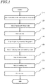
- FIG. 1 is a flowchart illustrating the method for producing a soldered product.
- the invention of the present application includes (1) a step of providing a solder and a temporary fixing agent, (2) a step of temporarily fixing the solder, (4) a step of vaporizing the temporary fixing agent, (5) a step of reducing the solder and soldering targets, and (6) a step of melting the solder.
- the method further includes (3) an inert gas step, (7) a vacuum breaking step, or (8) a cooling step.
- prepare means creating a state where a solder and a temporary fixing agent are present.
- a solder and a temporary fixing agent which already exist may be provided, or a temporary fixing agent may be provided by preparation.
- a temporary fixing agent is an agent that is used to fix the solder to the soldering target temporarily.
- the method for applying the temporary fixing agent is not particularly limited.
- an inert gas nitrogen or argon may be used.
- the temporary fixing agent starts to vaporize first.
- the solder and the soldering target which have a melting temperature higher than the vaporization temperature, do not melt and gaps are formed between the solder and the soldering target because of their surface irregularities.
- the reduction may take place either simultaneously with or after the vaporization of the temporary fixing agent.
- the reduction may take place under either normal pressure or reduced pressure (vacuum).
- the term “reduction” means a process of removing oxide films or the like on surfaces of the soldering target and the solder during soldering.
- the reducing gas include a formic acid gas, gases of carboxylic acids, gases of organic acids other than carboxylic acids, gases of organic compounds other than organic acids and reductive gases other than organic compounds (such as a hydrogen gas). From the viewpoint of lowering the reduction temperature to below the melting temperature of the solder and the viewpoint of availability, a formic acid gas is preferable as the reducing gas.
- the melting temperature of the solder is any temperature higher than the reduction temperature, and is preferably 10 to 50°C higher than the reduction temperature in this embodiment.
- voids formed in the solder by air entrained in the molten solder can be reduced in size or eliminated.
- the cooling may be either natural cooling or forced cooling.
- the soldered product is produced by the solidification of the molten solder. In the method of the present invention, the soldered product does not need washing because no residue remains.
- the vaporization temperature of the temporary fixing agent, the melting points of the solder and the soldering target and the reduction temperature of the reducing gas have the following relationship under a predetermined gas pressure (such as normal pressure or reduced pressure).
- the term "melting point” means the temperature at which the substance melts regardless of the gas pressure. Vaporization temperature of temporary agent ⁇ reduction temperature ⁇ melting points of solder and soldering target
- a preformed (molded) solder is used. Because a preformed solder is used, the amount of solder can be increased compared to soldering using a paste alone. In addition, when a preformed solder is used, the precise solder amount can be determined.
- solder refers to a preformed solder
- the alloy composition of the solder is not particularly limited.
- Various types of solder alloys presently used in bump formation or mounting on printed-circuit boards can be used. Examples include lead-free solder alloys used as lead-free solders, such as Sn-Ag solder, Sn-Ag-Cu solder, Sn-Ag-Cu-Bi solder, Sn-Ag-In-Bi solder, Sn-Cu solder, Sn-Zn solder and Sn-Bi solder.
- the solder may be in any form such as foil, sheet, washer, ring, pellet, disk, ribbon, ingot (rod), wire (cable), powder (grains), cube, cuboid, ball and tape as long as it can be fixed temporary with a temporary fixing agent.
- a foil or ball shape is preferred.
- the solder foil has a thickness of approximately 100 ⁇ m, for example.
- a temporary fixing agent is used to temporarily fix the solder to the soldering target.
- a temporary fixing agent may be a solvent.
- a viscosity modifier may be added to a solvent depending on the shape of the solder. The viscosity of the temporary fixing agent is adjusted to a level at which the solder can be temporarily fixed, and the amount of the viscosity modifier is adjusted as appropriate depending on the shape of the solder.
- the types and amounts of the solvent and viscosity modifier may be changed as appropriate based on the degree of viscosity adjustment.
- the solvent and the viscosity modifier may be mixed with stirring, or mixed with heating and stirring.
- the temporary fixing agent completely vaporizes at the gas pressure and temperature at which the solder melts and does not leave any residues after solder bonding.
- a commonly used liquid solvent or high-viscosity solvent may be used.
- examples include aniline, amyl alcohol, isobutyl alcohol, ethanol, ethylene glycol monomethyl ether, ethylene glycol monomethyl ether acetate, ethyl lactate, ethylene glycol ethyl ether, ethylene glycol ethyl ether acetate, ethylene glycol propyl ether, diethylene glycol dimethyl ether, dipropylene glycol dimethyl ether, diethylene glycol ethyl methyl ether, diethylene glycol isopropyl methyl ether, dipropylene glycol monomethyl ether, diethylene glycol diethyl ether, diethylene glycol monoethyl ether, dimethyl sulfoxide, propylene glycol, propylene glycol monomethyl ether, propylene glycol methyl ether acetate, propylene glycol diacetate, propanol, butyl alcohol, water, 2-phenoxy ethanol, 1,
- the solvent vaporizes at gas pressure and temperature equal to or lower than the gas pressure and temperature during reduction.
- the temperature at which the solvent vaporizes is any temperature equal to or lower than the reduction temperature, and is, for example, 0 to 100°C.
- a mechanism for adjusting the pressure of atmosphere enables a solvent that has a boiling point higher than the reduction temperature under normal pressure to vaporize at a temperature lower than the reduction temperature.
- the solvent needs to vaporize at a temperature equal to or lower than the reduction temperature under a predetermined gas pressure.
- the viscosity modifier adjusts the viscosity of the temporary fixing agent or promotes adherence of substances.
- the viscosity modifier vaporizes at gas pressure and temperature equal to or lower than those during reduction and is not an active material (non-ionic). Because the reduction temperature is determined according to the type of the reducing gas, the viscosity modifier is selected as appropriate depending on the reducing gas.
- Examples include urea, silica, polymers (such as acrylic acid-based polymers and carboxylic acid-based polymers), hardened castor oil, beeswax and carnauba wax. These viscosity modifiers may be used singly or in combination of two or more kinds.
- a viscosity modifier that can be vaporized at the gas pressure and temperature during reduction is preferred because the viscosity modifier does not remain in the solder as residues and because the viscosity modifier does not cause corrosion of the soldering targets (metals) and eliminates the need for washing since it not an active material.
- the temporary fixing agent when formic acid is used as the reducing gas and the reduction temperature is about 200°C, it is preferred that the temporary fixing agent vaporizes by the time of reduction.
- the temporary fixing agent may be vaporized during the temperature rise or a temperature-maintaining period for vaporizing the temporary fixing agent may be provided.
- the use of formic acid is preferred because formic acid enables reduction to be carried out at a lower temperature compared to other reducing gases.
- soldering apparatus 1 in FIG. 2 the steps relating to the apparatus in the method for producing a soldered product of the present application are described more specifically.
- the apparatus that can be used in the present invention is not limited to the soldering apparatus 1.
- FIG. 2 is a general configuration diagram of the soldering apparatus 1.
- the soldering apparatus 1 comprises: a treatment part 10 having a chamber 11 defining a treatment space 11s that is a space in which the members to be bonded are soldered to each other; a formic acid supply part 20 that supplies a formic acid gas F as a reducing gas to the chamber 11; a catalyst unit 33 that detoxifies the formic acid gas F in the soldering apparatus 1 before it is discharged; a controller 50 that controls the operation of the soldering apparatus 1; and a housing 100 that houses the treatment part 10, the formic acid supply part 20, the catalyst unit 33, and the controller 50.
- the soldering apparatus 1 is an apparatus in which a substrate W and an electronic component P as soldering targets are bonded with a solder S.
- the substrate W and the electronic component P both have a metal portion on a surface thereof, and bonded so that the metal portions can be electrically conductive with each other via the solder.
- a temporary fixing agent A is first applied to the substrate W and the solder S is placed on the temporary fixing agent A to fix it temporarily. Further, the temporary fixing agent A is applied to the solder S and the electronic component P is placed on the temporary fixing agent A to fix it temporarily.
- the substrate W and the electronic component P are transported into the chamber 11 with the temporary fixing agent A/solder S/temporary fixing agent A interposed therebetween, and the solder S is melted to bond the substrate W and the electronic component P after the temporary fixing agent A is vaporized in the chamber 11.
- the substrate W, the solder S and the electronic component P stacked on top of each other with the solder still unmelted are referred to as "to-be-bonded members B" (the substrate W, the solder S and the electronic component P), and the product obtained by melting the solder S and bonding the substrate W and the electronic component P is referred to as a "soldered product C.”
- the chamber 11 is configured to make the treatment space 11s airtight by closing a carry-in/out port 11a with a shutter 11d.
- the material and shape of the chamber 11 are selected so that it can endure even when the pressure in the treatment space 11s is reduced to approximately 10 Pa (absolute pressure).
- a carrier plate 12 on which the to-be-bonded members B are placed, and a heater 13 for heating the carrier plate 12 are provided.
- the heater 13 is configured to be able to heat the carrier plate 12 to a bonding temperature that is higher than the melting temperature of the solder.
- the formic acid supply part 20 directs the formic acid gas F into the chamber 11. While the formic acid gas F is used as the reducing gas in this description, any gas that can reduce metal oxides formed on the surfaces to be bonded of the substrate W and the electronic component P other than the formic acid gas F may be used. In this description, the formic acid gas F is used from the viewpoint of lowering the reduction temperature to below the melting temperature of the solder and the viewpoint of availability.
- the catalyst unit 33 is a device for detoxifying formic acid in the exhaust gas E discharged from the soldering apparatus 1 to such a level the environment is not affected.
- gas G is a collective term for the gases discharged from the chamber 11.
- a vacuum pump 31 is installed as a pressure reduction pump that discharges the gas G in the chamber 11 so that the pressure in the chamber 11 can be reduced to approximately 10 Pa (absolute pressure).
- the controller 50 is configured to be able to open and close the shutter 11d.
- the controller 50 is also configured to be able to heat the carrier plate 12 by switching between on and off of the heater 13 and varying the output of the heater 13.
- the controller 50 is also configured to be able to supply the formic acid gas F toward the chamber 11.
- the controller 50 is also configured to be able to control the start and stop of the vacuum pump 31. In the controller 50, a sequence of operation of the soldering apparatus 1 (which is described later) is stored.
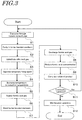
- FIG. 3 is a flowchart, illustrating a solder bonding procedure for the soldered product in a case where the soldering apparatus 1 is used.
- FIG. 2 is a flowchart, illustrating a solder bonding procedure for the soldered product in a case where the soldering apparatus 1 is used.
- the controller 50 activates the vacuum pump 31 to start discharge of the gas G in the chamber 11 (S1) before opening the shutter 11d. Then, the controller 50 moves the carrier plate 12 until most part of the carrier plate 12 is outside the chamber 11. By discharging the gas G in the chamber 11 from the chamber 11 before the shutter 11d is opened, the gas G in the chamber 11 can be prevented from flowing out of the soldering apparatus 1 through the carry-in/out port 11a when the shutter 11d is opened. After the shutter 11d is opened and most part of the carrier plate 12 is moved out of the chamber 11, the to-be-bonded members B are placed on the carrier plate 12. Then, as the carrier plate 12 is moved into the chamber 11, the to-be-bonded members B are carried into the chamber 11 (step of carrying in the to-be-bonded members: S2).
- the controller 50 closes the shutter 11d to make the chamber 11 airtight. Then, in order to remove the atmosphere that has entered the chamber 11 while the shutter 11d was open and create an inert gas atmosphere, the controller 50 discharges the gas G in the chamber 11 and then introduces an inert gas N. By repeating this procedure, the oxygen concentration in the chamber 11 is reduced (step of substituting with an inert gas: S3).
- the oxygen concentration is preferably 5 ppm or lower.
- the inert gas N is a nitrogen gas, for example.
- the controller 50 turns on the heater 13 to increase the temperature of the carrier plate 12 or, more specifically, the temperature of the to-be-bonded members B, to a temperature at which the temporary fixing agent A vaporizes (evaporates) (S4).
- the temporary fixing agent A evaporates and is removed from the to-be-bonded members B.
- the pressure inside the chamber 11 may be reduced to a vacuum (reduced pressure) in order to accelerate the evaporation of the temporary fixing agent A.
- the vaporization temperature may be equal to the following reduction temperature.
- the vaporization temperature is equal to the reduction temperature, evaporation of a portion of the temporary fixing agent A and reduction of the to-be-bonded members B occur simultaneously.
- step (S4) and steps (S5) and (S6) as subsequent steps occur concurrently.
- the controller 50 keeps the heater 13 on to increase the temperature of the carrier plate 12 or, more specifically, the temperature of the to-be-bonded members B, to the reduction temperature (S5).
- the reduction temperature is the temperature at which the oxides on the to-be-bonded members B are reduced by formic acid.
- the controller 50 supplies a formic acid gas F from the formic acid supply part 20 into the chamber 11 (S6).
- the reduction temperature is lower than the melting temperature of the solder S, the solder S does not melt, and the formic acid gas penetrates into the gaps formed as a result of vaporization of the temporary fixing agent A and favorably removes oxide film before the to-be-bonded members B are solder-bonded to each other.
- the formic acid gas F When the formic acid gas F is supplied after a vacuum is created inside the chamber 11, the formic acid gas F readily penetrates into the gaps.
- the step of increasing the temperature of the to-be-bonded members B to the reduction temperature (S5) and the step of supplying the formic acid gas F into the chamber 11 (S6) correspond to the reduction steps.
- the output of the heater 13 is increased, with the atmosphere of the formic acid gas F in the chamber 11 maintained to increase the temperature of the carrier plate 12 or, more specifically, the temperature of the to-be-bonded members B, to the bonding temperature in order to melt the solder and solder-bond the to-be-bonded members B (bonding step: S7).
- the bonding temperature is any temperature higher than the melting temperature of the solder S, and is 30 to 50°C higher than the melting temperature in this embodiment.
- the controller 50 turns off the heater 13.
- the temperature of the to-be-bonded members B decreases, and the solder solidifies when the temperature falls below its melting point.
- the carrier plate 12 may be forcibly cooled to accelerate solidification of the solder.
- the vacuum pump 31 is activated and a main exhaust valve 41v is opened to discharge the formic acid gas F from the chamber 11 (S8), and the inert gas N is introduced to return the pressure in the chamber 11 to normal pressure.
- the formic acid gas F discharged from the chamber 11 flows into the catalyst unit 33.
- the formic acid gas F is subjected to decomposition of the formic acid in the catalyst unit 33, and discharged from the soldering apparatus 1 as an exhaust gas E with a formic acid concentration reduced to a predetermined level or lower and detoxified (S9).
- the controller 50 determines whether continuous operation is performed (S11). When continuous operation is performed, the procedure returns to the step of discharging the gas G in the chamber 11 (S1). When continuous operation is not performed, maintenance operation is performed (S12).
- solder bonding using the formic acid gas F can be accomplished appropriately and completely within the soldering apparatus 1.
- appropriate soldering or vacuum soldering can be carried out using the solder S, the temporary fixing agent A, and the formic acid gas F.
- the to-be-bonded members may be members other than the substrate W and the electronic component P as long as they have a metal portion suitable for solder bonding on their surfaces.
- the to-be-bonded members B are heated to the bonding temperature and fusion-bonded to each other under an atmosphere of the formic acid gas F in the above description, the to-be-bonded members B are heated to the bonding temperature and fusion-bonded to each other in a vacuum (for example, about 100 Pa (absolute pressure)).
- a vacuum for example, about 100 Pa (absolute pressure)
- the vacuum in the chamber 11 may be broken by introducing an inert gas N after the heater 13 is turned off.
- the inert gas N is introduced after the solder is melted, cavities (voids) can be compressed and squashed.
- the reduction steps (S5, S6) and the bonding step (S7) may be carried out to solder-bond the to-be-bonded members B under normal pressure without creating a vacuum.
- the method for producing a soldered product of the present application may further comprise a coating step of coating the soldering targets that have undergone solder bonding. Because the solder bonding according to the present invention generates almost no residue, no problem arises about the adhesion with a coating agent. Thus, the soldered portions are appropriately protected when coated in the coating step.
- solder bonding is carried out after the to-be-bonded members as soldering targets are temporarily fixed using a temporary fixing agent.
- solder bonding can be accomplished very easily.
Landscapes
- Engineering & Computer Science (AREA)
- Mechanical Engineering (AREA)
- Manufacturing & Machinery (AREA)
- Microelectronics & Electronic Packaging (AREA)
- Physics & Mathematics (AREA)
- Optics & Photonics (AREA)
- Electric Connection Of Electric Components To Printed Circuits (AREA)
- Die Bonding (AREA)
Description
- The present invention relates to a method for producing a soldered product, and, more particularly, to a method for producing a soldered product by which soldering can be accomplished without using a jig when soldering is carried out in a soldering apparatus.
- In solder bonding, generally, a jig (also called pallet) is used to fix soldering targets and solder so that the soldering targets and solder can be held in a predetermined position and bonded to each other without misalignment.
-
Patent Document 1 discloses a positioning jig for a semiconductor chip that enables a semiconductor chip to be placed in a predetermined position without misalignment on an insulated circuit board and properly solder-bonded thereto (Patent Document 1, paragraphs 0001 and 0006 to 0010). - However, such a jig must be prepared for each shape of the soldering targets depending on its shape. In addition, attachment and detachment of a jig take time and place a burden on an operator. Another problem is that heat for solder welding is taken away by the jig.
-
EP2587900 relates to a soldering method capable of alleviating positional displacement between substrates even though a step of removing flux can be omitted is provided. A temporary bonding agent is applied onto multiple substrates and a heater heats the substrates while the substrates are temporarily bonded with the temporary bonding agent interposed therebetween, and before the solder is melted or while the solder is melted, the temporary bonding agent is evaporated, and the substrates are bonded with solder with the melted solder interposed therebetween. - Patent Document 1: Japanese patent application publication no.
2013-65662 JP-A-2013-65662 - In view of the above problems, an object of the present invention is to provide a method for producing a soldered product by which soldering can be accomplished without using a jig.
- For accomplishing the above object, a method for producing a soldered product according to a first aspect of the present invention comprises: a provision step of providing a solder and a temporary fixing agent for temporarily fixing the solder; a temporary fixing step of temporarily fixing the solder to a soldering target with the temporary fixing agent; a vaporization step of placing the soldering target with the solder temporarily fixed thereto in a vacuum or heating the soldering target with the solder temporarily fixed thereto to a predetermined temperature lower than the melting temperature of the solder, to vaporize the temporary fixing agent in order to form gaps between the solder and the soldering target; a reduction step, performed concurrently with or after the vaporization step, of reducing, with a reducing gas at a predetermined temperature lower than the melting temperature of the solder, the solder and the soldering target left in the vaporization step; and a solder melting step, performed after the reduction step, of heating the soldering target to a predetermined temperature equal to or higher than the melting temperature of the solder to melt the solder. The method further comprises an inert gas step, performed before the vaporization step, of placing the soldering target with the solder temporarily fixed thereto in an inert gas, wherein, in the solder melting step, the solder is melted by heating the soldering target to a temperature equal to or higher than the melting temperature of the solder while the soldering target is in the vacuum. The method further comprises a vacuum breaking step, performed after the solder melting step, of increasing pressure to break the vacuum in order to compress or eliminate cavities or voids in the solder, wherein the solder is in a molten state in the vacuum breaking step, and a cooling step, performed after the vacuum breaking step, of cooling the soldering target, wherein the molten solder is cooled and solidified
- A solder means an alloy utilized for soldering.
- The term "in a vacuum" means in a space having a pressure lower than that of atmosphere (so-called a reduced pressure).
- A surface of a material that apparently looks smooth and flat has countless irregularities in an atomic or molecular level. Thus, with the above configuration, gaps are formed between the solder and the soldering targets because of the above irregularities after the vaporization of the temporary fixing agent. In the present invention, effective reduction of the solder and the soldering targets can be achieved by introducing the reducing gas into the gaps.
- In addition, creating a vacuum accelerates vaporization of the temporary fixing agent. Further, a temporary fixing agent having a boiling point under normal pressure is higher than the reduction temperature can be used. Because the temporary fixing agent can be vaporized efficiently as described above, the types of usable solvents can be increased.
- As noted above, the method comprises an inert gas step, performed before the vaporization step, of placing the soldering target with the solder temporarily fixed thereto in an inert gas.
- With this configuration, it is possible to prevent the solder and the soldering targets from being oxidized and corroded by a trace amount of oxygen or other gases present in the atmosphere.
- A method for producing a soldered product according to an embodiment described herein is the method for producing a soldered product according to the above first aspect of the present invention, in which, in the vaporization step, the temporary fixing agent is vaporized by heating the soldering target in a vacuum.
- With this configuration, vaporization of the temporary fixing agent can be accelerated. Further, a temporary fixing agent having a boiling point under normal pressure is higher than the reduction temperature can be used. Because the temporary fixing agent can be vaporized efficiently as described above, the types of usable solvents can be increased.
- A method for producing a soldered product according to another embodiment is the method for producing a soldered product according to any one of the above aspects and embodiments, in which, in the reduction step, the soldering target is reduced by introducing the reducing gas into the gaps while the soldering target is in the vacuum.
- With this configuration, it is possible to facilitate penetration of the reducing gas into the gap between the solder and the soldering targets.
- As discussed above, in the solder melting step, the solder is melted by heating the soldering target to a temperature equal to or higher than the melting temperature of the solder while the soldering target is in the vacuum, and the method further comprises: a vacuum breaking step, performed after the solder melting step, of increasing pressure to break the vacuum in order to compress or eliminate cavities (voids) in the solder; and a cooling step, performed after the vacuum breaking step, of cooling the soldering target.
- With this configuration, the cavities (voids) can be squashed while the solder is in a molten state in the vacuum breaking step and the solder can be solidified after the cavities are squashed. Thus, the decrease of fatigue life caused by voids in the solder can be restrained.
- A method for producing a soldered product according to a further embodiment is the method for producing a soldered product according to any one of the above aspects and embodiments, in which the solder is a preformed solder, the temporary fixing agent contains a solvent and a viscosity modifier, and the temporary fixing agent has a boiling point lower than the melting temperature of the solder.
- With this configuration, because the boiling point of the temporary fixing agent is lower than the solder melting temperature, the temporary fixing agent completely vaporizes before the solder reaches its melting temperature and is prevented from being entrained into the solder after the solder melts.
- A method for producing a soldered product according to a further embodiment is the method for producing a soldered product according to any one of the above aspects and embodiments, in which the solder is a preformed solder, the temporary fixing agent is a solvent, and the solvent has a boiling point lower than the melting temperature of the solder.
- With this configuration, because the boiling point of the solvent is lower than the solder melting temperature, the solvent completely vaporizes before the solder reaches its melting temperature and is prevented from being entrained into the solder after the solder melts. In addition, the temporary fixing agent can be prepared very easily. Further, the temporary fixing agent can be formed without using harmful substances such as active materials.
- A method for producing a soldered product according to another embodiment is the method for producing a soldered product according to any one of the above aspects and embodiments, in which the reducing gas is a formic acid gas.
- With this configuration, the solder and the soldering target can be reduced at a temperature lower than 300°C.
- According to the present invention, because no jig is used in soldering, the burden on an operator can be reduced, and the time for the soldering step can be reduced with improved production efficiency. In addition, there is no possibility that heat for solder welding is taken away. Further, because the temporary fixing agent vaporizes, flux residues and so on that may remain after soldering can be reduced and the soldered product needs no washing.
-
-
FIG. 1 is a flowchart, illustrating a method for producing a soldered product of the present invention. -
FIG. 2 is a general configuration diagram of asoldering apparatus 1. -
FIG. 3 is a flowchart, illustrating in detail the steps relating to a soldering apparatus in the method for producing a soldered product of the present invention. A case where thesoldering apparatus 1 is used is taken for description. - Description will hereinafter be made of an embodiment of the present invention with reference to the drawings. The same or corresponding members are denoted with the same or similar reference numerals in all the drawings, and their descriptions are not repeated. Further, the present invention is not limited to the following embodiments.
- Referring to
FIG. 1 , a method for producing a soldered product according to a first embodiment of the present invention is described. The method for producing a soldered product of the present application is a production method in a case where a soldering apparatus is used to carry out soldering. -
FIG. 1 is a flowchart illustrating the method for producing a soldered product. The invention of the present application includes (1) a step of providing a solder and a temporary fixing agent, (2) a step of temporarily fixing the solder, (4) a step of vaporizing the temporary fixing agent, (5) a step of reducing the solder and soldering targets, and (6) a step of melting the solder. The method further includes (3) an inert gas step, (7) a vacuum breaking step, or (8) a cooling step. - In the following, each step is described in detail.
- This is a step of preparing a solder and a temporary fixing agent. The term "prepare" means creating a state where a solder and a temporary fixing agent are present. A solder and a temporary fixing agent which already exist may be provided, or a temporary fixing agent may be provided by preparation.
- A temporary fixing agent is an agent that is used to fix the solder to the soldering target temporarily.
- This is a step where the temporary fixing agent is applied to the soldering target and the solder is placed on the applied temporary fixing agent to fix the solder temporarily. The method for applying the temporary fixing agent is not particularly limited.
- This is a step where the solder and the soldering target are placed in an inert gas atmosphere. As the inert gas, nitrogen or argon may be used.
- This is a step where the temporary fixing agent is vaporized by heating or depressurizing (vacuuming).
- For example, when the soldering target, the temporary fixing agent and the solder are heated, the temporary fixing agent starts to vaporize first. When the temporary fixing agent vaporizes, the solder and the soldering target, which have a melting temperature higher than the vaporization temperature, do not melt and gaps are formed between the solder and the soldering target because of their surface irregularities.
- This is a step where heating is continued to the reduction temperature to vaporize the temporary fixing agent completely and, simultaneously, to reduce the solder and the soldering target with the reducing gas. The reduction may take place either simultaneously with or after the vaporization of the temporary fixing agent. The reduction may take place under either normal pressure or reduced pressure (vacuum).
- Here, the term "reduction" means a process of removing oxide films or the like on surfaces of the soldering target and the solder during soldering. Examples of the reducing gas include a formic acid gas, gases of carboxylic acids, gases of organic acids other than carboxylic acids, gases of organic compounds other than organic acids and reductive gases other than organic compounds (such as a hydrogen gas). From the viewpoint of lowering the reduction temperature to below the melting temperature of the solder and the viewpoint of availability, a formic acid gas is preferable as the reducing gas.
- This is a step where heating is further continued to the solder melting temperature to accomplish soldering.
- A solder that does not melt at the temperature for reduction with the reducing gas and under the gas pressure during reduction is preferred. In other words, the melting temperature of the solder is any temperature higher than the reduction temperature, and is preferably 10 to 50°C higher than the reduction temperature in this embodiment.
- This is a step where, when solder is melted under vacuum, the pressure is increased after the solder is melted to compress cavities (voids) in the solder. By this step, voids formed in the solder by air entrained in the molten solder can be reduced in size or eliminated.
- This is a step where the molten solder is cooled and solidified. The cooling may be either natural cooling or forced cooling. The soldered product is produced by the solidification of the molten solder. In the method of the present invention, the soldered product does not need washing because no residue remains.
- In the present invention, the vaporization temperature of the temporary fixing agent, the melting points of the solder and the soldering target and the reduction temperature of the reducing gas have the following relationship under a predetermined gas pressure (such as normal pressure or reduced pressure). The term "melting point" means the temperature at which the substance melts regardless of the gas pressure.

- In the invention of the present application, a preformed (molded) solder is used. Because a preformed solder is used, the amount of solder can be increased compared to soldering using a paste alone. In addition, when a preformed solder is used, the precise solder amount can be determined.
- In this specification, the term "solder" refers to a preformed solder.
- The alloy composition of the solder is not particularly limited. Various types of solder alloys presently used in bump formation or mounting on printed-circuit boards can be used. Examples include lead-free solder alloys used as lead-free solders, such as Sn-Ag solder, Sn-Ag-Cu solder, Sn-Ag-Cu-Bi solder, Sn-Ag-In-Bi solder, Sn-Cu solder, Sn-Zn solder and Sn-Bi solder.
- The solder may be in any form such as foil, sheet, washer, ring, pellet, disk, ribbon, ingot (rod), wire (cable), powder (grains), cube, cuboid, ball and tape as long as it can be fixed temporary with a temporary fixing agent. For reasons for easiness of temporary fixing, a foil or ball shape is preferred. The solder foil has a thickness of approximately 100 µm, for example.
- A temporary fixing agent is used to temporarily fix the solder to the soldering target. For example, by using only a solvent as a temporary fixing agent, a thin and light object such as solder foil can be temporarily fixed by the surface tension of the solvent. In other words, the temporary fixing agent may be a solvent. Alternatively, a viscosity modifier may be added to a solvent depending on the shape of the solder. The viscosity of the temporary fixing agent is adjusted to a level at which the solder can be temporarily fixed, and the amount of the viscosity modifier is adjusted as appropriate depending on the shape of the solder.
- As described above, the types and amounts of the solvent and viscosity modifier may be changed as appropriate based on the degree of viscosity adjustment. The solvent and the viscosity modifier may be mixed with stirring, or mixed with heating and stirring.
- Preferably, the temporary fixing agent completely vaporizes at the gas pressure and temperature at which the solder melts and does not leave any residues after solder bonding.
- As the solvent, a commonly used liquid solvent or high-viscosity solvent may be used. Examples include aniline, amyl alcohol, isobutyl alcohol, ethanol, ethylene glycol monomethyl ether, ethylene glycol monomethyl ether acetate, ethyl lactate, ethylene glycol ethyl ether, ethylene glycol ethyl ether acetate, ethylene glycol propyl ether, diethylene glycol dimethyl ether, dipropylene glycol dimethyl ether, diethylene glycol ethyl methyl ether, diethylene glycol isopropyl methyl ether, dipropylene glycol monomethyl ether, diethylene glycol diethyl ether, diethylene glycol monoethyl ether, dimethyl sulfoxide, propylene glycol, propylene glycol monomethyl ether, propylene glycol methyl ether acetate, propylene glycol diacetate, propanol, butyl alcohol, water, 2-phenoxy ethanol, 1,4-dioxane, and 3-methoxy-3-methyl-1-butanol. These solvents may be used singly or in combination of two or more kinds. The solvent is preferably ethanol, propanol or water for reasons of availability, environmental impact and low boiling point.
- Preferably, the solvent vaporizes at gas pressure and temperature equal to or lower than the gas pressure and temperature during reduction. The temperature at which the solvent vaporizes is any temperature equal to or lower than the reduction temperature, and is, for example, 0 to 100°C. A mechanism for adjusting the pressure of atmosphere enables a solvent that has a boiling point higher than the reduction temperature under normal pressure to vaporize at a temperature lower than the reduction temperature. As described above, the solvent needs to vaporize at a temperature equal to or lower than the reduction temperature under a predetermined gas pressure.
- The viscosity modifier adjusts the viscosity of the temporary fixing agent or promotes adherence of substances. Preferably, the viscosity modifier vaporizes at gas pressure and temperature equal to or lower than those during reduction and is not an active material (non-ionic). Because the reduction temperature is determined according to the type of the reducing gas, the viscosity modifier is selected as appropriate depending on the reducing gas.
- Examples include urea, silica, polymers (such as acrylic acid-based polymers and carboxylic acid-based polymers), hardened castor oil, beeswax and carnauba wax. These viscosity modifiers may be used singly or in combination of two or more kinds.
- A viscosity modifier that can be vaporized at the gas pressure and temperature during reduction is preferred because the viscosity modifier does not remain in the solder as residues and because the viscosity modifier does not cause corrosion of the soldering targets (metals) and eliminates the need for washing since it not an active material.
- As one example, when formic acid is used as the reducing gas and the reduction temperature is about 200°C, it is preferred that the temporary fixing agent vaporizes by the time of reduction. Thus, the temporary fixing agent may be vaporized during the temperature rise or a temperature-maintaining period for vaporizing the temporary fixing agent may be provided. The use of formic acid is preferred because formic acid enables reduction to be carried out at a lower temperature compared to other reducing gases.
- Using the
soldering apparatus 1 inFIG. 2 , the steps relating to the apparatus in the method for producing a soldered product of the present application are described more specifically. However, the apparatus that can be used in the present invention is not limited to thesoldering apparatus 1. -
FIG. 2 is a general configuration diagram of thesoldering apparatus 1. Thesoldering apparatus 1 comprises: atreatment part 10 having achamber 11 defining atreatment space 11s that is a space in which the members to be bonded are soldered to each other; a formicacid supply part 20 that supplies a formic acid gas F as a reducing gas to thechamber 11; acatalyst unit 33 that detoxifies the formic acid gas F in thesoldering apparatus 1 before it is discharged; acontroller 50 that controls the operation of thesoldering apparatus 1; and ahousing 100 that houses thetreatment part 10, the formicacid supply part 20, thecatalyst unit 33, and thecontroller 50. - The
soldering apparatus 1 is an apparatus in which a substrate W and an electronic component P as soldering targets are bonded with a solder S. The substrate W and the electronic component P both have a metal portion on a surface thereof, and bonded so that the metal portions can be electrically conductive with each other via the solder. Before transportation into thechamber 11, a temporary fixing agent A is first applied to the substrate W and the solder S is placed on the temporary fixing agent A to fix it temporarily. Further, the temporary fixing agent A is applied to the solder S and the electronic component P is placed on the temporary fixing agent A to fix it temporarily. As described above, the substrate W and the electronic component P are transported into thechamber 11 with the temporary fixing agent A/solder S/temporary fixing agent A interposed therebetween, and the solder S is melted to bond the substrate W and the electronic component P after the temporary fixing agent A is vaporized in thechamber 11. - In the following, the substrate W, the solder S and the electronic component P stacked on top of each other with the solder still unmelted are referred to as "to-be-bonded members B" (the substrate W, the solder S and the electronic component P), and the product obtained by melting the solder S and bonding the substrate W and the electronic component P is referred to as a "soldered product C."
- The
chamber 11 is configured to make thetreatment space 11s airtight by closing a carry-in/outport 11a with ashutter 11d. The material and shape of thechamber 11 are selected so that it can endure even when the pressure in thetreatment space 11s is reduced to approximately 10 Pa (absolute pressure). In thechamber 11, acarrier plate 12 on which the to-be-bonded members B are placed, and aheater 13 for heating thecarrier plate 12 are provided. - The
heater 13 is configured to be able to heat thecarrier plate 12 to a bonding temperature that is higher than the melting temperature of the solder. - The formic
acid supply part 20 directs the formic acid gas F into thechamber 11. While the formic acid gas F is used as the reducing gas in this description, any gas that can reduce metal oxides formed on the surfaces to be bonded of the substrate W and the electronic component P other than the formic acid gas F may be used. In this description, the formic acid gas F is used from the viewpoint of lowering the reduction temperature to below the melting temperature of the solder and the viewpoint of availability. - The
catalyst unit 33 is a device for detoxifying formic acid in the exhaust gas E discharged from thesoldering apparatus 1 to such a level the environment is not affected. The term "gas G" is a collective term for the gases discharged from thechamber 11. - A
vacuum pump 31 is installed as a pressure reduction pump that discharges the gas G in thechamber 11 so that the pressure in thechamber 11 can be reduced to approximately 10 Pa (absolute pressure). - The
controller 50 is configured to be able to open and close theshutter 11d. Thecontroller 50 is also configured to be able to heat thecarrier plate 12 by switching between on and off of theheater 13 and varying the output of theheater 13. Thecontroller 50 is also configured to be able to supply the formic acid gas F toward thechamber 11. Thecontroller 50 is also configured to be able to control the start and stop of thevacuum pump 31. In thecontroller 50, a sequence of operation of the soldering apparatus 1 (which is described later) is stored. - Referring continuously to
FIG. 3 , a method for producing a soldered product according to an embodiment of the present invention is described in detail in relation to the soldering apparatus.FIG. 3 is a flowchart, illustrating a solder bonding procedure for the soldered product in a case where thesoldering apparatus 1 is used. In the following description, when mention is made about the configuration of thesoldering apparatus 1, reference is made toFIG. 2 as appropriate. - When a button (not shown) for opening the
shutter 11d is pressed in order to carry the to-be-bonded members B into thesoldering apparatus 1, thecontroller 50 activates thevacuum pump 31 to start discharge of the gas G in the chamber 11 (S1) before opening theshutter 11d. Then, thecontroller 50 moves thecarrier plate 12 until most part of thecarrier plate 12 is outside thechamber 11. By discharging the gas G in thechamber 11 from thechamber 11 before theshutter 11d is opened, the gas G in thechamber 11 can be prevented from flowing out of thesoldering apparatus 1 through the carry-in/outport 11a when theshutter 11d is opened. After theshutter 11d is opened and most part of thecarrier plate 12 is moved out of thechamber 11, the to-be-bonded members B are placed on thecarrier plate 12. Then, as thecarrier plate 12 is moved into thechamber 11, the to-be-bonded members B are carried into the chamber 11 (step of carrying in the to-be-bonded members: S2). - After the to-be-bonded members B are carried into the
chamber 11, thecontroller 50 closes theshutter 11d to make thechamber 11 airtight. Then, in order to remove the atmosphere that has entered thechamber 11 while theshutter 11d was open and create an inert gas atmosphere, thecontroller 50 discharges the gas G in thechamber 11 and then introduces an inert gas N. By repeating this procedure, the oxygen concentration in thechamber 11 is reduced (step of substituting with an inert gas: S3). The oxygen concentration is preferably 5 ppm or lower. The inert gas N is a nitrogen gas, for example. - Next, the
controller 50 turns on theheater 13 to increase the temperature of thecarrier plate 12 or, more specifically, the temperature of the to-be-bonded members B, to a temperature at which the temporary fixing agent A vaporizes (evaporates) (S4). As the temperature increases to the vaporization temperature, the temporary fixing agent A evaporates and is removed from the to-be-bonded members B. In this embodiment, the pressure inside thechamber 11 may be reduced to a vacuum (reduced pressure) in order to accelerate the evaporation of the temporary fixing agent A. - While description is made of a case where the vaporization temperature is lower than the reduction temperature in this embodiment, the vaporization temperature may be equal to the following reduction temperature. When the vaporization temperature is equal to the reduction temperature, evaporation of a portion of the temporary fixing agent A and reduction of the to-be-bonded members B occur simultaneously. In other words, there is a case where step (S4) and steps (S5) and (S6) as subsequent steps occur concurrently.
- Next, the
controller 50 keeps theheater 13 on to increase the temperature of thecarrier plate 12 or, more specifically, the temperature of the to-be-bonded members B, to the reduction temperature (S5). The reduction temperature is the temperature at which the oxides on the to-be-bonded members B are reduced by formic acid. When the temperature rise to the reduction temperature is completed, thecontroller 50 supplies a formic acid gas F from the formicacid supply part 20 into the chamber 11 (S6). Here, in this embodiment, because the reduction temperature is lower than the melting temperature of the solder S, the solder S does not melt, and the formic acid gas penetrates into the gaps formed as a result of vaporization of the temporary fixing agent A and favorably removes oxide film before the to-be-bonded members B are solder-bonded to each other. When the formic acid gas F is supplied after a vacuum is created inside thechamber 11, the formic acid gas F readily penetrates into the gaps. The step of increasing the temperature of the to-be-bonded members B to the reduction temperature (S5) and the step of supplying the formic acid gas F into the chamber 11 (S6) correspond to the reduction steps. - After the reduction steps (S5, S6), the output of the
heater 13 is increased, with the atmosphere of the formic acid gas F in thechamber 11 maintained to increase the temperature of thecarrier plate 12 or, more specifically, the temperature of the to-be-bonded members B, to the bonding temperature in order to melt the solder and solder-bond the to-be-bonded members B (bonding step: S7). The bonding temperature is any temperature higher than the melting temperature of the solder S, and is 30 to 50°C higher than the melting temperature in this embodiment. - After the solder on the to-be-bonded members B is melted, the
controller 50 turns off theheater 13. By starting cooling, the temperature of the to-be-bonded members B decreases, and the solder solidifies when the temperature falls below its melting point. As a result, the soldered product C is obtained. At this time, thecarrier plate 12 may be forcibly cooled to accelerate solidification of the solder. Then, thevacuum pump 31 is activated and amain exhaust valve 41v is opened to discharge the formic acid gas F from the chamber 11 (S8), and the inert gas N is introduced to return the pressure in thechamber 11 to normal pressure. The formic acid gas F discharged from thechamber 11 flows into thecatalyst unit 33. The formic acid gas F is subjected to decomposition of the formic acid in thecatalyst unit 33, and discharged from thesoldering apparatus 1 as an exhaust gas E with a formic acid concentration reduced to a predetermined level or lower and detoxified (S9). - When the soldered product C is carried out of the chamber 11 (S10), the
controller 50 determines whether continuous operation is performed (S11). When continuous operation is performed, the procedure returns to the step of discharging the gas G in the chamber 11 (S1). When continuous operation is not performed, maintenance operation is performed (S12). - As described above, according to the
soldering apparatus 1, because the devices and units necessary to carry out solder bonding in a vacuum including thetreatment part 10, the formicacid supply part 20, thecatalyst unit 33 and thecontroller 50 are housed in thehousing 100, solder bonding using the formic acid gas F can be accomplished appropriately and completely within thesoldering apparatus 1. In addition, according to the method for producing a soldered product C according to this embodiment, appropriate soldering or vacuum soldering can be carried out using the solder S, the temporary fixing agent A, and the formic acid gas F. - While description is made using the substrate W and the electronic component P as to-be-bonded members B together with the solder S in the above description, the to-be-bonded members may be members other than the substrate W and the electronic component P as long as they have a metal portion suitable for solder bonding on their surfaces.
- While the to-be-bonded members B are heated to the bonding temperature and fusion-bonded to each other under an atmosphere of the formic acid gas F in the above description, the to-be-bonded members B are heated to the bonding temperature and fusion-bonded to each other in a vacuum (for example, about 100 Pa (absolute pressure)). When the to-be-bonded members B are solder-bonded to each other after a vacuum is created in the
chamber 11, the vacuum in thechamber 11 may be broken by introducing an inert gas N after theheater 13 is turned off. When the inert gas N is introduced after the solder is melted, cavities (voids) can be compressed and squashed. When the solder is solidified after the cavities are squashed, the decrease of fatigue life caused by voids in the solder can be further reduced. When the to-be-bonded members B are fusion-bonded to each other in a vacuum, the treatment and discharge steps (S8, S9) are carried out after the reduction steps (S5, S6). - While the to-be-bonded members B are heated to the bonding temperature and reduced in a vacuum (for example, about 100 Pa (absolute pressure)) in the above description, the reduction steps (S5, S6) and the bonding step (S7) may be carried out to solder-bond the to-be-bonded members B under normal pressure without creating a vacuum.
- The method for producing a soldered product of the present application may further comprise a coating step of coating the soldering targets that have undergone solder bonding. Because the solder bonding according to the present invention generates almost no residue, no problem arises about the adhesion with a coating agent. Thus, the soldered portions are appropriately protected when coated in the coating step.
- As described above, in the present invention, solder bonding is carried out after the to-be-bonded members as soldering targets are temporarily fixed using a temporary fixing agent. Thus, compared to a conventional method in which a jig is used to carry out solder bonding, solder bonding can be accomplished very easily.
- All references, including publications, patent applications, and patents, cited herein are hereby incorporated by reference to the same extent as if each reference were individually and specifically indicated to be incorporated by reference and were set forth in its entirety herein.
- The use of the terms "a" and "an" and "the" and similar referents in the context of describing the invention (especially in the context of the following claims) is to be construed to cover both the singular and the plural, unless otherwise indicated herein or clearly contradicted by context. The terms "comprising," "having," "including," and "containing" are to be construed as open-ended terms (i.e., meaning "including, but not limited to,") unless otherwise noted. Recitation of ranges of values herein are merely intended to serve as a shorthand method of referring individually to each separate value falling within the range, unless otherwise indicated herein, and each separate value is incorporated into the specification as if it were individually recited herein. All methods described herein can be performed in any suitable order unless otherwise indicated herein or otherwise clearly contradicted by context. The use of any and all examples, or exemplary language (e.g., "such as") provided herein, is intended merely to better illuminate the invention and does not pose a limitation on the scope of the invention unless otherwise claimed. No language in the specification should be construed as indicating any non-claimed element as essential to the practice of the invention.
-
- 1
- soldering apparatus
- 11
- chamber
- 11s
- treatment space
- 20
- formic acid supply part
- 31
- vacuum pump
- 33
- catalyst unit
- 41v
- main exhaust valve
- 50
- controller
- 100
- housing
- A
- temporary fixing agent
- B
- to-be-bonded members
- C
- soldered product
- F
- reducing gas, formic acid gas
- G
- gas
- N
- inert gas
- P
- electronic component
- S
- solder
- W
- substrate
Claims (6)
- A method for producing a soldered product, comprising:a provision step of providing a solder and a temporary fixing agent for temporarily fixing the solder;a temporary fixing step of temporarily fixing the solder to a soldering target with the temporary fixing agent;a vaporization step of placing the soldering target with the solder temporarily fixed thereto in a vacuum or heating the soldering target with the solder temporarily fixed thereto to a predetermined temperature lower than the melting temperature of the solder, to vaporize the temporary fixing agent in order to form gaps between the solder and the soldering target;a reduction step, performed concurrently with or after the vaporization step, of reducing, with a reducing gas at a predetermined temperature lower than the melting temperature of the solder, the solder and the soldering target left in the vaporization step; anda solder melting step, performed after the reduction step, of heating the soldering target to a predetermined temperature equal to or higher than the melting temperature of the solder to melt the solder; andfurther comprising:an inert gas step, performed before the vaporization step, of placing the soldering target with the solder temporarily fixed thereto in an inert gas; andwherein, in the solder melting step, the solder is melted by heating the soldering target to a temperature equal to or higher than the melting temperature of the solder while the soldering target is in the vacuum; andthe method further comprising:a vacuum breaking step, performed after the solder melting step, of increasing pressure to break the vacuum in order to compress or eliminate cavities or voids in the solder, wherein the solder is in a molten state in the vacuum breaking step; anda cooling step, performed after the vacuum breaking step, of cooling the soldering target, wherein the molten solder is cooled and solidified.
- A method for producing a soldered product according to Claim 1,
wherein, in the vaporization step, the temporary fixing agent is vaporized by heating the soldering target in a vacuum. - The method for producing a soldered product according to Claims 1 or 2,
wherein, in the reduction step, the reduction gas is introduced into the gaps to reduce the soldering target while the soldering target is in a vacuum. - The method for producing a soldered product according to any one of Claims 1 to 3, wherein
the solder is a preformed solder;
the temporary fixing agent contains a solvent and a viscosity modifier; and
the temporary fixing agent has a boiling point lower than the melting temperature of the solder. - The method for producing a soldered product according to any one of Claims 1 to 3, wherein
the solder is a preformed solder;
the temporary fixing agent is a solvent; and
the solvent has a boiling point lower than the melting temperature of the solder. - The method for producing a soldered product according to any one of Claims 1 to 5,
wherein the reducing gas is a formic acid gas.
Applications Claiming Priority (2)
| Application Number | Priority Date | Filing Date | Title |
|---|---|---|---|
| JP2015195198A JP6042956B1 (en) | 2015-09-30 | 2015-09-30 | Method for manufacturing soldered products |
| PCT/JP2016/078959 WO2017057649A1 (en) | 2015-09-30 | 2016-09-29 | Soldered product manufacturing method |
Publications (3)
| Publication Number | Publication Date |
|---|---|
| EP3358918A4 EP3358918A4 (en) | 2018-08-08 |
| EP3358918A1 EP3358918A1 (en) | 2018-08-08 |
| EP3358918B1 true EP3358918B1 (en) | 2019-11-13 |
Family
ID=57543812
Family Applications (1)
| Application Number | Title | Priority Date | Filing Date |
|---|---|---|---|
| EP16851820.7A Active EP3358918B1 (en) | 2015-09-30 | 2016-09-29 | Soldered product manufacturing method |
Country Status (6)
| Country | Link |
|---|---|
| US (1) | US10843300B2 (en) |
| EP (1) | EP3358918B1 (en) |
| JP (1) | JP6042956B1 (en) |
| CN (1) | CN108141965B (en) |
| TW (1) | TWI653116B (en) |
| WO (1) | WO2017057649A1 (en) |
Families Citing this family (17)
| Publication number | Priority date | Publication date | Assignee | Title |
|---|---|---|---|---|
| JP6042956B1 (en) * | 2015-09-30 | 2016-12-14 | オリジン電気株式会社 | Method for manufacturing soldered products |
| JP6627522B2 (en) | 2016-01-15 | 2020-01-08 | 富士電機株式会社 | Semiconductor device member, method of manufacturing semiconductor device, and semiconductor device member |
| WO2019163575A1 (en) * | 2018-02-23 | 2019-08-29 | 富士フイルム株式会社 | Method of manufacturing bonded body, temporary-fixing member, and stacked body |
| CN111757789A (en) * | 2018-03-05 | 2020-10-09 | 贺利氏德国有限两合公司 | Method for producing a sandwich arrangement |
| WO2019170211A1 (en) * | 2018-03-05 | 2019-09-12 | Heraeus Deutschland GmbH & Co. KG | Method for producing a sandwich arrangement |
| JP7356112B2 (en) * | 2018-03-09 | 2023-10-04 | 株式会社オリジン | Flux, solder paste, soldering process, soldering product manufacturing method, BGA package manufacturing method |
| JP6439893B1 (en) * | 2018-05-25 | 2018-12-19 | 千住金属工業株式会社 | Solder ball, solder joint and joining method |
| JP6476342B1 (en) * | 2018-10-15 | 2019-02-27 | オリジン電気株式会社 | Reducing gas supply device and method of manufacturing processed object |
| US11205633B2 (en) * | 2019-01-09 | 2021-12-21 | Kulicke And Soffa Industries, Inc. | Methods of bonding of semiconductor elements to substrates, and related bonding systems |
| US11515286B2 (en) | 2019-01-09 | 2022-11-29 | Kulicke And Soffa Industries, Inc. | Methods of bonding of semiconductor elements to substrates, and related bonding systems |
| JP6677844B1 (en) * | 2019-04-26 | 2020-04-08 | 株式会社オリジン | Heating device and method of manufacturing soldered object |
| US20220266367A1 (en) * | 2019-07-26 | 2022-08-25 | Origin Company, Limited | Soldered product manufacturing device and method for manufacturing soldered product |
| JP6860729B2 (en) * | 2019-07-26 | 2021-04-21 | 株式会社オリジン | Soldered product manufacturing equipment and soldered product manufacturing method |
| JP7145839B2 (en) * | 2019-12-18 | 2022-10-03 | 株式会社オリジン | Soldering substrate manufacturing method and soldering apparatus |
| JP7714291B2 (en) * | 2020-12-31 | 2025-07-29 | インターナショナル・ビジネス・マシーンズ・コーポレーション | Method and Apparatus (Assembling Chips to Substrates) |
| EP4064331A1 (en) * | 2021-03-25 | 2022-09-28 | Infineon Technologies AG | Method for attaching a first connection partner to a second connection partner |
| US12062636B2 (en) * | 2022-04-08 | 2024-08-13 | Kulicke And Soffa Industries, Inc. | Bonding systems, and methods of providing a reducing gas on a bonding system |
Family Cites Families (35)
| Publication number | Priority date | Publication date | Assignee | Title |
|---|---|---|---|---|
| JPS6042956B2 (en) * | 1978-03-18 | 1985-09-25 | カシオ計算機株式会社 | Musical sound waveform generator for electronic musical instruments |
| US4712721A (en) * | 1986-03-17 | 1987-12-15 | Raychem Corp. | Solder delivery systems |
| JP3294460B2 (en) * | 1995-03-06 | 2002-06-24 | 株式会社日立製作所 | Circuit board manufacturing method |
| JP3732639B2 (en) * | 1998-01-08 | 2006-01-05 | 株式会社日立製作所 | Soldering method and electronic device manufacturing method |
| JPH11224981A (en) * | 1998-02-06 | 1999-08-17 | Matsushita Electric Ind Co Ltd | Soldering method and solder bump forming method |
| JP2000216334A (en) * | 1999-01-25 | 2000-08-04 | Seiko Epson Corp | Semiconductor device |
| US6445589B2 (en) * | 1999-07-29 | 2002-09-03 | Delphi Technologies, Inc. | Method of extending life expectancy of surface mount components |
| JP4609617B2 (en) * | 2000-08-01 | 2011-01-12 | 日本電気株式会社 | Semiconductor device mounting method and mounting structure |
| JP3404021B2 (en) * | 2001-01-18 | 2003-05-06 | 富士通株式会社 | Soldering equipment |
| US7331502B2 (en) * | 2001-03-19 | 2008-02-19 | Sumitomo Bakelite Company, Ltd. | Method of manufacturing electronic part and electronic part obtained by the method |
| US6713318B2 (en) * | 2001-03-28 | 2004-03-30 | Intel Corporation | Flip chip interconnection using no-clean flux |
| US8274161B2 (en) * | 2002-07-01 | 2012-09-25 | Semigear Inc | Flux-free chip to substrate joint serial linear thermal processor arrangement |
| US20130175323A1 (en) * | 2002-07-01 | 2013-07-11 | Jian Zhang | Serial thermal linear processor arrangement |
| CN1477703A (en) * | 2002-08-02 | 2004-02-25 | ǧס������ҵ��ʽ���� | Solder ball assembly and production method thereof, method of forming solder bumps |
| US6841874B1 (en) * | 2002-11-01 | 2005-01-11 | Amkor Technology, Inc. | Wafer-level chip-scale package |
| JP4505783B2 (en) * | 2003-01-31 | 2010-07-21 | 日立金属株式会社 | Solder bump manufacturing method and manufacturing apparatus |
| JP4341036B2 (en) * | 2003-03-10 | 2009-10-07 | 日立金属株式会社 | Method and apparatus for mounting conductive ball |
| JP2005026579A (en) * | 2003-07-04 | 2005-01-27 | Fujitsu Ltd | Mounting method of electronic component with solder bump and flux fill used therefor |
| JP2006210761A (en) * | 2005-01-31 | 2006-08-10 | Fujitsu Ltd | Solder joining method and apparatus |
| JP2006222381A (en) * | 2005-02-14 | 2006-08-24 | Olympus Corp | Electronic component mounting method and manufacturing apparatus thereof |
| JP5215174B2 (en) * | 2005-05-26 | 2013-06-19 | アルファ ラヴァル コーポレイト アクチボラゲット | How to braze stainless steel articles |
| US20070007323A1 (en) * | 2005-07-06 | 2007-01-11 | International Business Machines Corporation | Standoff structures for surface mount components |
| JP2007180447A (en) * | 2005-12-28 | 2007-07-12 | Toyota Industries Corp | Soldering method, soldering apparatus, and semiconductor device manufacturing method |
| JP5210496B2 (en) * | 2006-03-27 | 2013-06-12 | 神港精機株式会社 | Manufacturing method of semiconductor device |
| CN101679837B (en) * | 2007-05-22 | 2013-10-30 | 六号元素有限公司 | Coated CBN |
| JP5807221B2 (en) * | 2010-06-28 | 2015-11-10 | アユミ工業株式会社 | Bonded structure manufacturing method, heat-melt treatment method, and system thereof |
| WO2012174384A1 (en) * | 2011-06-15 | 2012-12-20 | Promerus Llc | Thermally decomposable polymer compositions incorporating thermally activated base generators |
| JP5853525B2 (en) | 2011-09-16 | 2016-02-09 | 富士電機株式会社 | Semiconductor chip positioning jig and semiconductor device manufacturing method |
| TW201320207A (en) * | 2011-11-15 | 2013-05-16 | Ableprint Technology Co Ltd | Solder reflow method for suppressing solder-splash |
| US9293636B2 (en) * | 2012-08-01 | 2016-03-22 | Flextronics Ap, Llc | Solar cell pad dressing |
| WO2014099614A1 (en) * | 2012-12-17 | 2014-06-26 | Promerus, Llc | Thermally decomposable polymer composition for forming microelectric assemblies |
| JP6031059B2 (en) * | 2014-03-31 | 2016-11-24 | 信越化学工業株式会社 | Semiconductor device, stacked semiconductor device, post-sealing stacked semiconductor device, and manufacturing method thereof |
| WO2015174202A1 (en) * | 2014-05-13 | 2015-11-19 | 株式会社村田製作所 | Resin sealed module |
| JP6042956B1 (en) * | 2015-09-30 | 2016-12-14 | オリジン電気株式会社 | Method for manufacturing soldered products |
| US10668558B2 (en) * | 2016-03-29 | 2020-06-02 | Ngk Insulators, Ltd. | Metal wiring bonding structure and production method therefor |
-
2015
- 2015-09-30 JP JP2015195198A patent/JP6042956B1/en active Active
-
2016
- 2016-09-29 WO PCT/JP2016/078959 patent/WO2017057649A1/en not_active Ceased
- 2016-09-29 US US15/764,268 patent/US10843300B2/en not_active Expired - Fee Related
- 2016-09-29 CN CN201680052916.9A patent/CN108141965B/en active Active
- 2016-09-29 EP EP16851820.7A patent/EP3358918B1/en active Active
- 2016-09-30 TW TW105131585A patent/TWI653116B/en active
Non-Patent Citations (1)
| Title |
|---|
| None * |
Also Published As
| Publication number | Publication date |
|---|---|
| JP6042956B1 (en) | 2016-12-14 |
| TWI653116B (en) | 2019-03-11 |
| EP3358918A4 (en) | 2018-08-08 |
| US10843300B2 (en) | 2020-11-24 |
| CN108141965A (en) | 2018-06-08 |
| US20180326545A1 (en) | 2018-11-15 |
| JP2017069459A (en) | 2017-04-06 |
| EP3358918A1 (en) | 2018-08-08 |
| WO2017057649A1 (en) | 2017-04-06 |
| CN108141965B (en) | 2019-05-31 |
| TW201718161A (en) | 2017-06-01 |
Similar Documents
| Publication | Publication Date | Title |
|---|---|---|
| US10843300B2 (en) | Method for producing soldered product | |
| US12138714B2 (en) | Flux, solder paste, soldering process, method for producing soldered product, and method for producing BGA package | |
| US10610981B2 (en) | Solder paste for reduction gas, and method for producing soldered product | |
| JP3120695B2 (en) | Electronic circuit manufacturing method | |
| JP2010219158A (en) | Reflow soldering method | |
| EP2481511B1 (en) | Gold removal from electronic components | |
| WO2018096917A1 (en) | Soldering method | |
| WO2014020751A1 (en) | Component having electrode dissolution prevention layer, and manufacturing method therefor | |
| EP1313587A1 (en) | Rapid surface cooling of solder droplets by flash evaporation | |
| JP5885135B2 (en) | Heat-melt treatment method and heat-melt treatment apparatus | |
| JP2008263153A (en) | 4D soldering equipment | |
| JP3385925B2 (en) | Electronic circuit manufacturing method | |
| JP5821797B2 (en) | Electronic component manufacturing method and electronic component manufacturing apparatus | |
| JP2000049450A (en) | Electronic component soldering method | |
| JP2016140870A (en) | Method for forming a solder bump | |
| JP5962123B2 (en) | Component mounting method and component mounting apparatus | |
| JP2014157859A (en) | Solder spatter suppression reflow method | |
| JP2564152C (en) |
Legal Events
| Date | Code | Title | Description |
|---|---|---|---|
| STAA | Information on the status of an ep patent application or granted ep patent |
Free format text: STATUS: THE INTERNATIONAL PUBLICATION HAS BEEN MADE |
|
| PUAI | Public reference made under article 153(3) epc to a published international application that has entered the european phase |
Free format text: ORIGINAL CODE: 0009012 |
|
| STAA | Information on the status of an ep patent application or granted ep patent |
Free format text: STATUS: REQUEST FOR EXAMINATION WAS MADE |
|
| 17P | Request for examination filed |
Effective date: 20180423 |
|
| A4 | Supplementary search report drawn up and despatched |
Effective date: 20180709 |
|
| AK | Designated contracting states |
Kind code of ref document: A1 Designated state(s): AL AT BE BG CH CY CZ DE DK EE ES FI FR GB GR HR HU IE IS IT LI LT LU LV MC MK MT NL NO PL PT RO RS SE SI SK SM TR |
|
| AX | Request for extension of the european patent |
Extension state: BA ME |
|
| DAV | Request for validation of the european patent (deleted) | ||
| DAX | Request for extension of the european patent (deleted) | ||
| STAA | Information on the status of an ep patent application or granted ep patent |
Free format text: STATUS: EXAMINATION IS IN PROGRESS |
|
| 17Q | First examination report despatched |
Effective date: 20190326 |
|
| REG | Reference to a national code |
Ref country code: DE Ref legal event code: R079 Ref document number: 602016024475 Country of ref document: DE Free format text: PREVIOUS MAIN CLASS: H05K0003340000 Ipc: B23K0035220000 |
|
| GRAP | Despatch of communication of intention to grant a patent |
Free format text: ORIGINAL CODE: EPIDOSNIGR1 |
|
| STAA | Information on the status of an ep patent application or granted ep patent |
Free format text: STATUS: GRANT OF PATENT IS INTENDED |
|
| RIC1 | Information provided on ipc code assigned before grant |
Ipc: B23K 35/26 20060101ALI20190611BHEP Ipc: B23K 1/00 20060101ALI20190611BHEP Ipc: H01L 21/04 20060101ALI20190611BHEP Ipc: B23K 35/22 20060101AFI20190611BHEP Ipc: H01L 21/52 20060101ALI20190611BHEP Ipc: B23K 1/20 20060101ALI20190611BHEP Ipc: H01L 23/00 20060101ALI20190611BHEP Ipc: H01L 21/683 20060101ALI20190611BHEP Ipc: B23K 101/42 20060101ALI20190611BHEP Ipc: B23K 35/38 20060101ALI20190611BHEP Ipc: B23K 35/36 20060101ALI20190611BHEP |
|
| INTG | Intention to grant announced |
Effective date: 20190628 |
|
| RAP1 | Party data changed (applicant data changed or rights of an application transferred) |
Owner name: ORIGIN COMPANY, LIMITED |
|
| GRAS | Grant fee paid |
Free format text: ORIGINAL CODE: EPIDOSNIGR3 |
|
| GRAA | (expected) grant |
Free format text: ORIGINAL CODE: 0009210 |
|
| STAA | Information on the status of an ep patent application or granted ep patent |
Free format text: STATUS: THE PATENT HAS BEEN GRANTED |
|
| AK | Designated contracting states |
Kind code of ref document: B1 Designated state(s): AL AT BE BG CH CY CZ DE DK EE ES FI FR GB GR HR HU IE IS IT LI LT LU LV MC MK MT NL NO PL PT RO RS SE SI SK SM TR |
|
| REG | Reference to a national code |
Ref country code: CH Ref legal event code: EP Ref country code: AT Ref legal event code: REF Ref document number: 1201159 Country of ref document: AT Kind code of ref document: T Effective date: 20191115 |
|
| REG | Reference to a national code |
Ref country code: DE Ref legal event code: R096 Ref document number: 602016024475 Country of ref document: DE |
|
| REG | Reference to a national code |
Ref country code: IE Ref legal event code: FG4D |
|
| REG | Reference to a national code |
Ref country code: NL Ref legal event code: MP Effective date: 20191113 |
|
| REG | Reference to a national code |
Ref country code: LT Ref legal event code: MG4D |
|
| PG25 | Lapsed in a contracting state [announced via postgrant information from national office to epo] |
Ref country code: PT Free format text: LAPSE BECAUSE OF FAILURE TO SUBMIT A TRANSLATION OF THE DESCRIPTION OR TO PAY THE FEE WITHIN THE PRESCRIBED TIME-LIMIT Effective date: 20200313 Ref country code: SE Free format text: LAPSE BECAUSE OF FAILURE TO SUBMIT A TRANSLATION OF THE DESCRIPTION OR TO PAY THE FEE WITHIN THE PRESCRIBED TIME-LIMIT Effective date: 20191113 Ref country code: LV Free format text: LAPSE BECAUSE OF FAILURE TO SUBMIT A TRANSLATION OF THE DESCRIPTION OR TO PAY THE FEE WITHIN THE PRESCRIBED TIME-LIMIT Effective date: 20191113 Ref country code: FI Free format text: LAPSE BECAUSE OF FAILURE TO SUBMIT A TRANSLATION OF THE DESCRIPTION OR TO PAY THE FEE WITHIN THE PRESCRIBED TIME-LIMIT Effective date: 20191113 Ref country code: GR Free format text: LAPSE BECAUSE OF FAILURE TO SUBMIT A TRANSLATION OF THE DESCRIPTION OR TO PAY THE FEE WITHIN THE PRESCRIBED TIME-LIMIT Effective date: 20200214 Ref country code: NO Free format text: LAPSE BECAUSE OF FAILURE TO SUBMIT A TRANSLATION OF THE DESCRIPTION OR TO PAY THE FEE WITHIN THE PRESCRIBED TIME-LIMIT Effective date: 20200213 Ref country code: BG Free format text: LAPSE BECAUSE OF FAILURE TO SUBMIT A TRANSLATION OF THE DESCRIPTION OR TO PAY THE FEE WITHIN THE PRESCRIBED TIME-LIMIT Effective date: 20200213 Ref country code: LT Free format text: LAPSE BECAUSE OF FAILURE TO SUBMIT A TRANSLATION OF THE DESCRIPTION OR TO PAY THE FEE WITHIN THE PRESCRIBED TIME-LIMIT Effective date: 20191113 Ref country code: PL Free format text: LAPSE BECAUSE OF FAILURE TO SUBMIT A TRANSLATION OF THE DESCRIPTION OR TO PAY THE FEE WITHIN THE PRESCRIBED TIME-LIMIT Effective date: 20191113 Ref country code: NL Free format text: LAPSE BECAUSE OF FAILURE TO SUBMIT A TRANSLATION OF THE DESCRIPTION OR TO PAY THE FEE WITHIN THE PRESCRIBED TIME-LIMIT Effective date: 20191113 |
|
| PG25 | Lapsed in a contracting state [announced via postgrant information from national office to epo] |
Ref country code: HR Free format text: LAPSE BECAUSE OF FAILURE TO SUBMIT A TRANSLATION OF THE DESCRIPTION OR TO PAY THE FEE WITHIN THE PRESCRIBED TIME-LIMIT Effective date: 20191113 Ref country code: IS Free format text: LAPSE BECAUSE OF FAILURE TO SUBMIT A TRANSLATION OF THE DESCRIPTION OR TO PAY THE FEE WITHIN THE PRESCRIBED TIME-LIMIT Effective date: 20200313 Ref country code: RS Free format text: LAPSE BECAUSE OF FAILURE TO SUBMIT A TRANSLATION OF THE DESCRIPTION OR TO PAY THE FEE WITHIN THE PRESCRIBED TIME-LIMIT Effective date: 20191113 |
|
| PG25 | Lapsed in a contracting state [announced via postgrant information from national office to epo] |
Ref country code: AL Free format text: LAPSE BECAUSE OF FAILURE TO SUBMIT A TRANSLATION OF THE DESCRIPTION OR TO PAY THE FEE WITHIN THE PRESCRIBED TIME-LIMIT Effective date: 20191113 |
|
| PG25 | Lapsed in a contracting state [announced via postgrant information from national office to epo] |
Ref country code: CZ Free format text: LAPSE BECAUSE OF FAILURE TO SUBMIT A TRANSLATION OF THE DESCRIPTION OR TO PAY THE FEE WITHIN THE PRESCRIBED TIME-LIMIT Effective date: 20191113 Ref country code: DK Free format text: LAPSE BECAUSE OF FAILURE TO SUBMIT A TRANSLATION OF THE DESCRIPTION OR TO PAY THE FEE WITHIN THE PRESCRIBED TIME-LIMIT Effective date: 20191113 Ref country code: RO Free format text: LAPSE BECAUSE OF FAILURE TO SUBMIT A TRANSLATION OF THE DESCRIPTION OR TO PAY THE FEE WITHIN THE PRESCRIBED TIME-LIMIT Effective date: 20191113 Ref country code: EE Free format text: LAPSE BECAUSE OF FAILURE TO SUBMIT A TRANSLATION OF THE DESCRIPTION OR TO PAY THE FEE WITHIN THE PRESCRIBED TIME-LIMIT Effective date: 20191113 Ref country code: ES Free format text: LAPSE BECAUSE OF FAILURE TO SUBMIT A TRANSLATION OF THE DESCRIPTION OR TO PAY THE FEE WITHIN THE PRESCRIBED TIME-LIMIT Effective date: 20191113 |
|
| REG | Reference to a national code |
Ref country code: DE Ref legal event code: R097 Ref document number: 602016024475 Country of ref document: DE |
|
| REG | Reference to a national code |
Ref country code: AT Ref legal event code: MK05 Ref document number: 1201159 Country of ref document: AT Kind code of ref document: T Effective date: 20191113 |
|
| PG25 | Lapsed in a contracting state [announced via postgrant information from national office to epo] |
Ref country code: SM Free format text: LAPSE BECAUSE OF FAILURE TO SUBMIT A TRANSLATION OF THE DESCRIPTION OR TO PAY THE FEE WITHIN THE PRESCRIBED TIME-LIMIT Effective date: 20191113 Ref country code: SK Free format text: LAPSE BECAUSE OF FAILURE TO SUBMIT A TRANSLATION OF THE DESCRIPTION OR TO PAY THE FEE WITHIN THE PRESCRIBED TIME-LIMIT Effective date: 20191113 |
|
| PLBE | No opposition filed within time limit |
Free format text: ORIGINAL CODE: 0009261 |
|
| STAA | Information on the status of an ep patent application or granted ep patent |
Free format text: STATUS: NO OPPOSITION FILED WITHIN TIME LIMIT |
|
| 26N | No opposition filed |
Effective date: 20200814 |
|
| PG25 | Lapsed in a contracting state [announced via postgrant information from national office to epo] |
Ref country code: SI Free format text: LAPSE BECAUSE OF FAILURE TO SUBMIT A TRANSLATION OF THE DESCRIPTION OR TO PAY THE FEE WITHIN THE PRESCRIBED TIME-LIMIT Effective date: 20191113 Ref country code: AT Free format text: LAPSE BECAUSE OF FAILURE TO SUBMIT A TRANSLATION OF THE DESCRIPTION OR TO PAY THE FEE WITHIN THE PRESCRIBED TIME-LIMIT Effective date: 20191113 |
|
| PG25 | Lapsed in a contracting state [announced via postgrant information from national office to epo] |
Ref country code: IT Free format text: LAPSE BECAUSE OF FAILURE TO SUBMIT A TRANSLATION OF THE DESCRIPTION OR TO PAY THE FEE WITHIN THE PRESCRIBED TIME-LIMIT Effective date: 20191113 |
|
| REG | Reference to a national code |
Ref country code: CH Ref legal event code: PL |
|
| GBPC | Gb: european patent ceased through non-payment of renewal fee |
Effective date: 20200929 |
|
| REG | Reference to a national code |
Ref country code: BE Ref legal event code: MM Effective date: 20200930 |
|
| PG25 | Lapsed in a contracting state [announced via postgrant information from national office to epo] |
Ref country code: LU Free format text: LAPSE BECAUSE OF NON-PAYMENT OF DUE FEES Effective date: 20200929 |
|
| PG25 | Lapsed in a contracting state [announced via postgrant information from national office to epo] |
Ref country code: FR Free format text: LAPSE BECAUSE OF NON-PAYMENT OF DUE FEES Effective date: 20200930 |
|
| PG25 | Lapsed in a contracting state [announced via postgrant information from national office to epo] |
Ref country code: CH Free format text: LAPSE BECAUSE OF NON-PAYMENT OF DUE FEES Effective date: 20200930 Ref country code: BE Free format text: LAPSE BECAUSE OF NON-PAYMENT OF DUE FEES Effective date: 20200930 Ref country code: IE Free format text: LAPSE BECAUSE OF NON-PAYMENT OF DUE FEES Effective date: 20200929 Ref country code: GB Free format text: LAPSE BECAUSE OF NON-PAYMENT OF DUE FEES Effective date: 20200929 Ref country code: LI Free format text: LAPSE BECAUSE OF NON-PAYMENT OF DUE FEES Effective date: 20200930 |
|
| PG25 | Lapsed in a contracting state [announced via postgrant information from national office to epo] |
Ref country code: TR Free format text: LAPSE BECAUSE OF FAILURE TO SUBMIT A TRANSLATION OF THE DESCRIPTION OR TO PAY THE FEE WITHIN THE PRESCRIBED TIME-LIMIT Effective date: 20191113 Ref country code: MT Free format text: LAPSE BECAUSE OF FAILURE TO SUBMIT A TRANSLATION OF THE DESCRIPTION OR TO PAY THE FEE WITHIN THE PRESCRIBED TIME-LIMIT Effective date: 20191113 Ref country code: CY Free format text: LAPSE BECAUSE OF FAILURE TO SUBMIT A TRANSLATION OF THE DESCRIPTION OR TO PAY THE FEE WITHIN THE PRESCRIBED TIME-LIMIT Effective date: 20191113 |
|
| PG25 | Lapsed in a contracting state [announced via postgrant information from national office to epo] |
Ref country code: MK Free format text: LAPSE BECAUSE OF FAILURE TO SUBMIT A TRANSLATION OF THE DESCRIPTION OR TO PAY THE FEE WITHIN THE PRESCRIBED TIME-LIMIT Effective date: 20191113 Ref country code: MC Free format text: LAPSE BECAUSE OF FAILURE TO SUBMIT A TRANSLATION OF THE DESCRIPTION OR TO PAY THE FEE WITHIN THE PRESCRIBED TIME-LIMIT Effective date: 20191113 |
|
| PGFP | Annual fee paid to national office [announced via postgrant information from national office to epo] |
Ref country code: DE Payment date: 20250919 Year of fee payment: 10 |