EP3358711A1 - Wireless power transmission system - Google Patents
Wireless power transmission system Download PDFInfo
- Publication number
- EP3358711A1 EP3358711A1 EP16850539.4A EP16850539A EP3358711A1 EP 3358711 A1 EP3358711 A1 EP 3358711A1 EP 16850539 A EP16850539 A EP 16850539A EP 3358711 A1 EP3358711 A1 EP 3358711A1
- Authority
- EP
- European Patent Office
- Prior art keywords
- relay
- power
- amplitude
- power transmission
- transmission
- Prior art date
- Legal status (The legal status is an assumption and is not a legal conclusion. Google has not performed a legal analysis and makes no representation as to the accuracy of the status listed.)
- Granted
Links
Images










Classifications
-
- H—ELECTRICITY
- H02—GENERATION; CONVERSION OR DISTRIBUTION OF ELECTRIC POWER
- H02M—APPARATUS FOR CONVERSION BETWEEN AC AND AC, BETWEEN AC AND DC, OR BETWEEN DC AND DC, AND FOR USE WITH MAINS OR SIMILAR POWER SUPPLY SYSTEMS; CONVERSION OF DC OR AC INPUT POWER INTO SURGE OUTPUT POWER; CONTROL OR REGULATION THEREOF
- H02M3/00—Conversion of DC power input into DC power output
- H02M3/22—Conversion of DC power input into DC power output with intermediate conversion into AC
- H02M3/24—Conversion of DC power input into DC power output with intermediate conversion into AC by static converters
- H02M3/28—Conversion of DC power input into DC power output with intermediate conversion into AC by static converters using discharge tubes with control electrode or semiconductor devices with control electrode to produce the intermediate AC
- H02M3/325—Conversion of DC power input into DC power output with intermediate conversion into AC by static converters using discharge tubes with control electrode or semiconductor devices with control electrode to produce the intermediate AC using devices of a triode or a transistor type requiring continuous application of a control signal
- H02M3/335—Conversion of DC power input into DC power output with intermediate conversion into AC by static converters using discharge tubes with control electrode or semiconductor devices with control electrode to produce the intermediate AC using devices of a triode or a transistor type requiring continuous application of a control signal using semiconductor devices only
-
- H—ELECTRICITY
- H02—GENERATION; CONVERSION OR DISTRIBUTION OF ELECTRIC POWER
- H02J—ELECTRIC POWER NETWORKS; CIRCUIT ARRANGEMENTS OR SYSTEMS FOR SUPPLYING OR DISTRIBUTING ELECTRIC POWER; SYSTEMS FOR STORING ELECTRIC ENERGY
- H02J50/00—Circuit arrangements or systems for wireless supply or distribution of electric power
- H02J50/10—Circuit arrangements or systems for wireless supply or distribution of electric power using inductive coupling
- H02J50/12—Circuit arrangements or systems for wireless supply or distribution of electric power using inductive coupling of the resonant type
-
- H—ELECTRICITY
- H02—GENERATION; CONVERSION OR DISTRIBUTION OF ELECTRIC POWER
- H02J—ELECTRIC POWER NETWORKS; CIRCUIT ARRANGEMENTS OR SYSTEMS FOR SUPPLYING OR DISTRIBUTING ELECTRIC POWER; SYSTEMS FOR STORING ELECTRIC ENERGY
- H02J50/00—Circuit arrangements or systems for wireless supply or distribution of electric power
- H02J50/50—Circuit arrangements or systems for wireless supply or distribution of electric power using additional energy repeaters between transmitting devices and receiving devices
-
- H—ELECTRICITY
- H02—GENERATION; CONVERSION OR DISTRIBUTION OF ELECTRIC POWER
- H02J—ELECTRIC POWER NETWORKS; CIRCUIT ARRANGEMENTS OR SYSTEMS FOR SUPPLYING OR DISTRIBUTING ELECTRIC POWER; SYSTEMS FOR STORING ELECTRIC ENERGY
- H02J50/00—Circuit arrangements or systems for wireless supply or distribution of electric power
- H02J50/80—Circuit arrangements or systems for wireless supply or distribution of electric power involving the exchange of data, concerning supply or distribution of electric power, between transmitting devices and receiving devices
-
- H—ELECTRICITY
- H02—GENERATION; CONVERSION OR DISTRIBUTION OF ELECTRIC POWER
- H02M—APPARATUS FOR CONVERSION BETWEEN AC AND AC, BETWEEN AC AND DC, OR BETWEEN DC AND DC, AND FOR USE WITH MAINS OR SIMILAR POWER SUPPLY SYSTEMS; CONVERSION OF DC OR AC INPUT POWER INTO SURGE OUTPUT POWER; CONTROL OR REGULATION THEREOF
- H02M7/00—Conversion of AC power input into DC power output; Conversion of DC power input into AC power output
- H02M7/42—Conversion of DC power input into AC power output without possibility of reversal
- H02M7/44—Conversion of DC power input into AC power output without possibility of reversal by static converters
- H02M7/48—Conversion of DC power input into AC power output without possibility of reversal by static converters using discharge tubes with control electrode or semiconductor devices with control electrode
- H02M7/53—Conversion of DC power input into AC power output without possibility of reversal by static converters using discharge tubes with control electrode or semiconductor devices with control electrode using devices of a triode or transistor type requiring continuous application of a control signal
- H02M7/537—Conversion of DC power input into AC power output without possibility of reversal by static converters using discharge tubes with control electrode or semiconductor devices with control electrode using devices of a triode or transistor type requiring continuous application of a control signal using semiconductor devices only, e.g. single switched pulse inverters
- H02M7/5387—Conversion of DC power input into AC power output without possibility of reversal by static converters using discharge tubes with control electrode or semiconductor devices with control electrode using devices of a triode or transistor type requiring continuous application of a control signal using semiconductor devices only, e.g. single switched pulse inverters in a bridge configuration
- H02M7/53871—Conversion of DC power input into AC power output without possibility of reversal by static converters using discharge tubes with control electrode or semiconductor devices with control electrode using devices of a triode or transistor type requiring continuous application of a control signal using semiconductor devices only, e.g. single switched pulse inverters in a bridge configuration with automatic control of output voltage or current
-
- H—ELECTRICITY
- H04—ELECTRIC COMMUNICATION TECHNIQUE
- H04B—TRANSMISSION
- H04B5/00—Near-field transmission systems, e.g. inductive or capacitive transmission systems
- H04B5/20—Near-field transmission systems, e.g. inductive or capacitive transmission systems characterised by the transmission technique; characterised by the transmission medium
- H04B5/24—Inductive coupling
-
- H—ELECTRICITY
- H04—ELECTRIC COMMUNICATION TECHNIQUE
- H04B—TRANSMISSION
- H04B5/00—Near-field transmission systems, e.g. inductive or capacitive transmission systems
- H04B5/40—Near-field transmission systems, e.g. inductive or capacitive transmission systems characterised by components specially adapted for near-field transmission
- H04B5/48—Transceivers
-
- H—ELECTRICITY
- H02—GENERATION; CONVERSION OR DISTRIBUTION OF ELECTRIC POWER
- H02M—APPARATUS FOR CONVERSION BETWEEN AC AND AC, BETWEEN AC AND DC, OR BETWEEN DC AND DC, AND FOR USE WITH MAINS OR SIMILAR POWER SUPPLY SYSTEMS; CONVERSION OF DC OR AC INPUT POWER INTO SURGE OUTPUT POWER; CONTROL OR REGULATION THEREOF
- H02M1/00—Details of apparatus for conversion
- H02M1/0067—Converter structures employing plural converter units, other than for parallel operation of the units on a single load
- H02M1/007—Plural converter units in cascade
Definitions
- the present disclosure relates to a wireless power transmission system that wirelessly transmits power.
- PTL 1 discloses a noncontact power transmission system that transmits power through magnetic resonance. This system includes a power transmission apparatus and a plurality of power reception apparatuses. It is disclosed that power can be transmitted even to a power reception apparatus outside a reachable range of power from the power transmission apparatus through magnetic resonance between coils of the plurality of power reception apparatuses. PTL 1 also discloses that each power reception apparatus can transmit data to the power transmission apparatus using a method such as amplitude modulation.
- a power transmission apparatus is a wireless power transmission system comprising:
- a wireless power transmission system can be achieved that hardly propagates an effect of data communication to another apparatus during power transmission.
- the present inventors have examined a wireless power transmission system employing multistage connection (also referred to as "cascade connection"), in which one or more relay apparatuses are provided between a power transmission apparatus and a power reception apparatus and a plurality of loads are driven.
- a wireless power transmission system can be suitably used for a device including a plurality of loads (e.g., motors), such as a robot arm illustrated in Fig. 1 .
- loads e.g., motors
- a plurality of loads e.g., motors
- a plurality of parts are rotated or moved by motors. Power, therefore, needs to be individually supplied to each motor to control the robot arm.
- a power supply supplies, in the existing art, power to loads through a large number of cables.
- Fig. 2A is a block diagram schematically illustrating an example of such a wireless power transmission system.
- a power transmission apparatus 100 connected to a power supply 50 wirelessly transmits power to a power reception apparatus 300 through a plurality of relay apparatuses 200.
- Each of the plurality of relay apparatuses 200 and the power reception apparatus 300 is connected to a load 400 and supplies a part of the received power to the load 400.
- Each relay apparatus 200 supplies power to the connected load 400 and transmits power to an apparatus in a subsequent stage (an adjacent relay apparatus 200 or the power reception apparatus 300) in a noncontact manner.
- stage closer to a power transmission apparatus than a relay apparatus in question will be expressed as a "previous stage”
- a stage closer to a power reception apparatus than the relay apparatus in question will be expressed as a "next stage” herein.
- Power transmission between apparatuses is performed by a power transmission antenna and a power reception antenna.
- the power transmission apparatus 100 includes a power transmission antenna
- the power reception apparatus 300 includes a power reception antenna.
- Each relay apparatus 200 includes both a power reception antenna and a power transmission antenna.
- Each antenna can be achieved, for example, by a resonant circuit including a coil and a capacitor or a circuit including a pair of electrodes. The former is used for power transmission through magnetic field coupling, and the latter is used for power transmission through electric field coupling.
- Each load 400 is not limited to a motor and can be an arbitrary load such as a camera or a lighting device. Each load 400 is driven by power from the connected relay apparatus 200 or power reception apparatus 300.
- Fig. 2A includes a plurality of relay apparatus 200, the number of relay apparatuses 200 may be one.
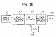
- Fig. 2B illustrates an example of a wireless power transmission system in which a relay apparatus 200 is provided between a power transmission apparatus 100 and a power reception apparatus 300.
- the power transmission apparatus 100 wirelessly transmits power to the power reception apparatus 300 through at least one relay apparatus 200.
- Power can be individually supplied to each load 400 without using cables connecting a power supply 50 and a plurality of loads 400.
- information is preferably transmitted between the power transmission apparatus 100, the relay apparatuses 200, and the power reception apparatus 300 in order to perform operations safely and stably.
- information indicating variation in a voltage or power supplied to each load 400, information specifying stopping of power transmission at a time of occurrence of an abnormality in each load 400, or the like can be transmitted from each of the relay apparatuses 200 and the power reception apparatus 300 to an apparatus in a previous stage.
- the apparatus in the previous stage can adjust a value of power to be transmitted or stop transmitting power.
- the transmission of information can be performed, for example, using a load modulation method in which a value of a load in a circuit is varied using a switch device.
- information (data) can be transmitted.
- An example of the transmission of data through amplitude modulation is disclosed, for example, in PTL 1.
- Fig. 3 is a block diagram illustrating an example (comparative example) of the configuration of relay apparatuses 200 having a function of communicating data through amplitude modulation.
- a wireless power transmission system including a plurality of relay apparatuses 200 is assumed here.
- the number of relay apparatuses 200 is denoted by N (N is an integer equal to or larger than 2), and the N relay apparatuses 200 sorted as first to N-th relay apparatuses in descending order of closeness to a power transmission apparatus 100 are assumed.
- the other relay apparatuses that are not illustrated have the same configuration.
- Each relay apparatus 200 includes a power reception antenna 210, a rectifier (rectifier circuit) 220, an inverter circuit 230, and a power transmission antenna 240.
- the power reception antenna 210 receives alternating current power transmitted from a power transmission antenna of an apparatus in a previous stage (the power transmission apparatus 100 or another relay apparatus 200).
- the rectifier 220 converts the alternating current power received by the power reception antenna 210 into direct current power and outputs the direct current power.
- a part of the direct current power output from the rectifier 220 is supplied to a load 400, and another part is supplied to the inverter circuit 230.
- the inverter circuit 230 converts the direct current power output from the rectifier 220 into alternating current power and supplies the alternating current power to the power transmission antenna 240.
- the power transmission antenna 240 transmits the alternating current power to an apparatus in a subsequent stage (an adjacent relay apparatus 200 or the power reception apparatus 300).
- the inverter circuit 230 is controlled by a control circuit 250 and a pulse
- Each relay apparatus 200 also includes, as components for transmitting data to the apparatus in the previous stage, an amplitude modulator 270 that modulates the amplitude of the voltage of the alternating current power received by the power reception antenna 210 in accordance with binary transmission data and a transmission data memory 290 storing binary transmission data.
- the amplitude modulator 270 modulates the amplitude of the voltage of the alternating current power output from the power reception antenna 210 by, for example, controlling a switch device in a load modulation circuit 275 connected to the rectifier 220. An effect of the modulation is propagated to the apparatus in the previous stage, and data is transmitted.
- each relay apparatus 200 also includes a demodulator 280 as a component for receiving data transmitted from the apparatus in the subsequent stage through the amplitude modulation described above.
- the demodulator 280 reads data transmitted from the apparatus in the subsequent stage by detecting changes in the amplitude of the voltage of the alternating current power output from the inverter circuit 230.
- the read data is stored in a received data memory 295 as received data.
- each relay apparatus 200 can transmit data to the apparatus in the previous stage and receive data from the apparatus in the subsequent stage. If the amplitude of the alternating current voltage input to the inverter circuit 230 is varied to transmit data to the apparatus in the previous stage, however, a problem arises that an effect of the variation propagates to the alternating current power output from the inverter circuit 230 to the power transmission antenna 240 and the demodulator 280 incorrectly receives the data.
- Fig. 4 is a diagram illustrating the problem.
- Fig. 4 illustrates an example of temporal changes in binary transmission data transmitted from a relay apparatus (e.g., an i-th relay apparatus) 200 to a previous stage, a voltage input to the inverter circuit 230, a voltage input to the power transmission antenna 240, and received data output from the demodulator 280.
- a relay apparatus e.g., an i-th relay apparatus
- switches illustrated in Fig. 8A which will be described later, are turned on, and when the value of the transmission data is 1, the switches illustrated in Fig. 8A , which will be described later, are turned off.
- the value of the transmission data is 1, the amplitude of the voltage of alternating current power input to the rectifier 220 becomes larger than when the value of the transmission data is 0.
- a value of the direct current voltage input to the inverter circuit 230 from the rectifier 220 therefore, is larger when the value of the transmission data is 1 than when the value of the transmission data is 0.
- an amplitude Va of the alternating current voltage input from the inverter circuit 230 to the power transmission antenna 240 when the value of the transmission data is 1 is larger than an amplitude Vb when the value of the transmission data is 0.
- the demodulator 280 detects changes in the amplitude although data is not being transmitted from the subsequent stage, and incorrectly receives data.
- An effect of the amplitude modulation performed by the amplitude modulator 270 propagates to a relay apparatus 200 and the power reception apparatus 300 in a subsequent stage.
- the above problem of interference therefore, can occur not only in a relay apparatus 200 that has transmitted data but also in another relay apparatus 200 or the power reception apparatus 300 in the subsequent stage. That is, while a relay apparatus 200 is transmitting data to an apparatus in a previous stage, not only data communication performed by the relay apparatus 200 but also data communication performed by an apparatus in a subsequent stage is affected.
- Fig. 5 is a diagram illustrating a problem at a time of data reception.
- Fig. 5 illustrates an example of temporal changes in received data transmitted to a certain relay apparatus (e.g., an i-th relay apparatus) 200 from a subsequent stage, a voltage input to the inverter circuit 230 of the relay apparatus 200, a voltage input to the power transmission antenna of an apparatus in a previous stage, and received data output from the demodulator of the apparatus in the previous stage.
- the relay apparatus 200 is only receiving data and is not transmitting data to the apparatus in the previous stage.
- the received data is 1, voltage in the relay apparatus 200 and a circuit of the apparatus in the previous stage is generally higher than when the received data is 0.
- the direct current voltage input to the inverter circuit 230 therefore, is higher when the received data is 1 than when the received data is 0.
- an amplitude Vd of the alternating current voltage input to the power transmission antenna of the apparatus in the previous stage is higher when the received data is 1 than an amplitude Vc when the received data is 0.
- the demodulator of the apparatus in the previous stage detects the variation between the amplitude Vd and the amplitude Vc and receives the same data.
- the reception of the same data can also occur in an apparatus in a yet earlier stage, and consequently interferes with data communication performed by the apparatus in the yet earlier stage.
- the present inventors have identified the above two problems that arise when data is transmitted and received and examined a configuration for solving these problems. As a result, the present inventors have found that at least one of the two problems can be solved by introducing, into a relay apparatus, control for eliminating variation in the amplitude of alternating current voltage caused by data communication. Aspects of the present disclosure will be described hereinafter.
- a wireless power transmission system is a wireless power transmission system comprising:
- the relay apparatus includes a relay amplitude modulator that, when the relay apparatus transmits binary relay transmission data to the power transmission apparatus through the electromagnetic coupling between the relay power reception antenna and the power transmission power transmission antenna, varies amplitude of voltage of the power transmission alternating current power received by the relay power reception antenna between a first amplitude (V1) and a second amplitude (V2), and a relay control circuit that performs, using the relay inverter circuit, control for eliminating a difference between a third amplitude (V3) of the relay alternating current power, which corresponds to the first amplitude (V1), and a fourth amplitude (V4) of the relay alternating current power, which corresponds to the second amplitude (V2).
- V3 third amplitude
- V4 fourth amplitude
- a wireless power transmission system is a wireless power transmission system comprising:
- V3 third amplitude
- V4 fourth amplitude
- a wireless power transmission system is a wireless power transmission system comprising:
- the relay apparatus includes a relay demodulator that is connected to the relay power transmission antenna and that receives binary relay received data by demodulating the binary power reception transmission data on the basis of a change in the voltage of the relay alternating current power input to the relay power transmission antenna, and a relay reverse control circuit that reverses a sign of the binary relay received data received by the relay demodulator and that performs, using the relay amplitude modulator, control for eliminating a difference between a first voltage (DC1) of the relay direct current power, which corresponds to the first amplitude (V1), and a second voltage (DC2) of the relay direct current power, which corresponds to the second amplitude (V2), on the basis of the reversed binary relay received data.
- DC1 first voltage
- DC2 second voltage
- a wireless power transmission system is a wireless power transmission system comprising:
- the difference between the first voltage (DC1) and the second voltage (DC2) of the relay direct current power when a certain relay apparatus is receiving data from an apparatus in a subsequent stage in the wireless power transmission system including the plurality of relay apparatuses can be almost perfectly eliminated.
- the unnecessary reception of data by an apparatus in a previous stage described with reference to Fig. 5 therefore, can be prevented.
- Fig. 6 is a block diagram illustrating the configuration of a wireless power transmission system according to a first embodiment of the present disclosure.
- the wireless power transmission system includes a power transmission apparatus 100, a relay apparatus 200, and a power reception apparatus 300.
- the present system corresponds to the configuration illustrated in Fig. 2B and includes one relay apparatus 200.
- the relay apparatus 200 has the same configuration as the relay apparatus 200 described with reference to Fig. 3 , but the operation of a relay control circuit 250 is different from that described above.
- the relay control circuit 250 controls a relay inverter circuit 230 such that the amplitude of the voltage of alternating current power output from the inverter circuit 230 does not vary.
- the relay apparatus 200 can correctly receive data from the power reception apparatus 300 even while the relay apparatus 200 is transmitting data.
- the power transmission apparatus 100 includes a power transmission inverter circuit 130 that converts direct current power input from an external direct current (DC) power supply 50 into alternating current power and that outputs the alternating current power and a power transmission power transmission antenna 140 that transmits the alternating current power output from the power transmission inverter circuit 130.
- the power transmission apparatus 100 also includes a pulse output circuit 160 that drives the power transmission inverter circuit 130, a power transmission control circuit 150 that controls the pulse output circuit 160, a power transmission demodulator 180 that demodulates data transmitted from the relay apparatus 200, and a received data memory 195.
- the relay apparatus 200 is electromagnetically coupled with the power transmission power transmission antenna 140 and includes a relay power reception antenna 240 that receives transmitted alternating current power (power transmission alternating current power), a relay rectifier 220 that converts the received power transmission alternating current power into direct current power (relay direct current power), the relay inverter circuit 230 that converts the relay direct current power into alternating current power (relay alternating current power), and a relay power transmission antenna 240 that wirelessly transmits the obtained relay alternating current power.
- a relay power reception antenna 240 that receives transmitted alternating current power (power transmission alternating current power)
- a relay rectifier 220 that converts the received power transmission alternating current power into direct current power (relay direct current power)
- the relay inverter circuit 230 that converts the relay direct current power into alternating current power (relay alternating current power)
- a relay power transmission antenna 240 that wirelessly transmits the obtained relay alternating current power.
- the relay apparatus 200 also includes a load modulation circuit 275 connected between the power reception antenna 210 and the rectifier 220, the relay amplitude modulator 270 that changes a value of a load of the load modulation circuit 275 in accordance with values of transmission data, and a transmission data memory 290 storing the transmission data.
- the relay apparatus 200 also includes a pulse output circuit 260 that supplies pulse signals to a plurality of switching elements included in the relay inverter circuit 230, the relay control circuit 250 that controls the pulse output circuit 260, a relay demodulator 280 that receives data by detecting changes in the amplitude of an alternating current voltage applied to the power transmission antenna 240, and a received data memory 295 storing the received data.
- the power reception apparatus 300 includes a power reception power reception antenna 310 that receives relay alternating current power transmitted from the relay power transmission antenna 240 and a power reception rectifier 320 that converts the alternating current power received by the power reception antenna 310 into direct current power (power reception direct current power) and that outputs the direct current power.
- the power reception apparatus 300 also includes a load modulation circuit 375 connected between the power reception antenna 310 and the rectifier 320, a power reception amplitude modulator 370 that controls the load modulation circuit 375 in such a way as to modulate the amplitude of the alternating current power received by the power reception antenna 310, and a transmission data memory 390 storing data to be transmitted to the relay apparatus 200.
- the power transmission power transmission antenna 140, the relay power reception antenna 210, the relay power transmission antenna 240, and the power reception power reception antenna 310 can each be achieved, for example, by a resonant circuit including a coil and a capacitor.
- Fig. 7 illustrates an example of an equivalent circuit of the antennas 140, 240, 210, and 310, which have the configuration of series resonant circuits.
- each antenna may have the configuration of a parallel resonant circuit.
- a coil in a power transmission antenna might be herein referred to as a power transmission coil
- a coil in a power reception antenna might be referred to as a power reception coil.
- each antenna may have a configuration for wirelessly transmitting power through electric field coupling instead of magnetic field coupling.
- each antenna can include two electrodes for transmitting or receiving power and a resonant circuit that includes an inductor and a capacitor.
- a power transmission antenna and a power reception antenna employing electric field coupling can be suitably used when power is wirelessly transmitted to a mobile device such as a carrier robot in a factory.
- the power reception apparatus 300 can be, for example, a tip of a robot arm, a rotation unit of a monitoring camera, or the like.
- the power transmission apparatus 100 is an apparatus that wirelessly supplies power to the relay apparatus 200 and can be mounted, for example, on a root of the robot arm or a fixing unit of the monitoring camera.
- the relay apparatus 200 can be, for example, a component connecting the root and the tip of the robot arm or a component connecting the fixing unit and the rotation unit of the monitoring camera.
- a load 400 can be, for example, a device including a motor, such as an actuator, mounted on the tip of the robot arm or an image capture device, such as a CCD camera, mounted on the rotation unit of the monitoring camera.
- the load 400 is connected to the relay rectifier 220 and the power reception rectifier 320 and driven by direct current power.
- the wireless power transmission system can communicate data between adjacent apparatuses while wirelessly transmitting power.
- a type of data to be transmitted can be, for example, information indicating a power value or a voltage in a circuit, a control signal or a signal indicating an abnormality from a connected load, or the like.
- the transmission data may be a response signal to an instruction or image (video) data.
- Fig. 8A is a diagram illustrating an example of the configuration of the load modulation circuit 275.
- the illustrated load modulation circuit 275 is connected between the power reception antenna 210 and the rectifier 220.
- the load modulation circuit 275 includes two switches and two capacitors connected parallel to the power reception antenna 210 and a resistor connected between a point between the two capacitors and the ground.
- the load modulation circuit 275 performs load modulation by switching open/close states of the two switches on the basis of controls signals from the amplitude modulator 270. More specifically, the load modulation circuit 275 changes a value of an overall load thereof by switching on/off states of the two switches and opening or closing a current route different from a route to the load 400. As a result, information can be transmitted to the power transmission apparatus 100.
- Fig. 8B is a diagram illustrating an example of the load modulation circuit 275 arranged in this manner.
- the load modulation circuit 275 is connected between the rectifier 220 and the load 400.
- the load modulation circuit 275 includes a resistor and a switch connected parallel to the rectifier 220.
- the load modulation circuit 275 can change an overall load of the power reception apparatus by switching an on/off state of the switch on the basis of a control signal from the amplitude modulator 270.
- FIGs. 8A and 8B illustrate an example the configuration of the relay amplitude modulator 270 and the relay load modulation circuit 275, the power reception amplitude modulator 370 and the power reception load modulation circuit 375 have the same configuration.
- the power transmission inverter circuit 130 and the relay inverter circuit 230 convert supplied direct current power into alternating current power using a plurality of switching elements.
- the pulse output circuits 160 and 260 and the control circuits 150 and 160 are used.
- the power transmission control circuit 150 and the relay control circuit 250 are each achieved, for example, by an integrated circuit including a processor such as a microcontroller (MCU).
- the pulse output circuits 160 and 260 are each achieved, for example, by a known gate driver.
- the control circuits 150 and 250 may be integrated with other circuit elements.
- the power transmission control circuit 150 and the relay control circuit 250 control pulse signals input to the switching elements from the pulse output circuits 160 and 260 by adjusting a power transmission parameter on the basis of the content of data received by the power transmission demodulator 180 and the relay demodulator 280, respectively. As a result, the frequency and amplitude of the alternating current power output from the inverter circuits 130 and 230 are adjusted to appropriate values.
- the power transmission parameter is a parameter for controlling timings at which the plurality of switching elements included in each inverter circuit are turned on (conductive state) and off (nonconductive state).
- the power transmission parameter can be the frequency of a pulse signal input to each switching element, a phase difference (also referred to as the "amount of phase shift") between two pulse signals input to two switching elements that are simultaneously turned on among the plurality of switching elements, a duty ratio of the pulse signal input to each switching element, or the like.
- Figs. 9A to 9D schematically illustrate the dependence of the amplitude of a voltage (also referred to as a coil end voltage) at both ends of the coil included in the relay power transmission antenna 240 upon the frequency, the amount of phase shift, the duty ratio, and a voltage supplied to the relay inverter circuit 230, respectively.
- a voltage also referred to as a coil end voltage
- the amplitude of the coil end voltage tends to decrease.
- Fig. 9B when the amount of phase shift is increased within a range of 0° to 180°, the amplitude of the coil end voltage decreases.
- Fig. 9C when the duty ratio is increased within a range of 0% to 50%, the amplitude of the coil end voltage increases.
- the relay control circuit 250 when the voltage supplied to the relay inverter circuit 230 is increased, the amplitude of the coil end voltage increases.
- the relay control circuit 250 therefore, can control the amplitude of the coil end voltage using at least any of the frequency, the amount of phase shift, the duty ratio, and the supplied voltage as a control parameter. It is to be noted that the voltage supplied to the inverter circuit 230 can be controlled when a DC-DC converter is provided between the relay rectifier 220 and the relay inverter circuit 230. With this configuration, the relay control circuit 250 can adjust a value of a voltage output from the DC-DC converter by changing the frequency of switching of switching elements included in the DC-DC converter.
- Fig. 10 is a diagram illustrating an example of the relay inverter circuit 230.
- the inverter circuit 230 includes a plurality of switching elements S1 to S4 whose conductive/nonconductive states change in accordance with pulse signals supplied from the pulse output circuit 260. By changing the conductive/nonconductive state of each switching element, input direct current power can be converted into alternating current power.
- a full-bridge inverter circuit including the four switching elements S1 to S4 is used.
- each switching element is an IGBT (Insulated-gate bipolar transistor), but a switching element of another type, such as a MOSFET (Metal Oxide Semiconductor Field-Effect Transistor) may be used, instead.
- IGBT Insulated-gate bipolar transistor
- MOSFET Metal Oxide Semiconductor Field-Effect Transistor
- the switching elements S1 and S4 (first switching element pair) output, when conductive, a voltage having the same polarity as a supplied direct current voltage.
- the switching elements S2 and S3 (second switching element pair) output, when conductive, a voltage having an opposite polarity to the supplied direct current voltage.
- the pulse output circuit 260 supplies pulse signals to gates of the switching elements S1 to S4 in accordance with an instruction from the control circuit 250.
- the pulse output circuit 260 can perform amplitude control by adjusting a phase difference between the two pulse signals supplied to the first switching element pair (S1 and S4) and a phase difference between the two pulse signals supplied to the second switching element pair (S2 and S3).
- Figs. 11A and 11B are diagrams illustrating the amplitude control based on the phase differences between the pulse signals.
- Fig. 11A schematically illustrates temporal changes in the four pulse signals and a voltage V output from the inverter circuit 230 at a time when an amount ⁇ of phase shift between the two pulse signals supplied to the switching elements S1 and S4 and the amount ⁇ of phase shift between the two pulse signals supplied to the switching elements S2 and S3 are 0 degree.
- Fig. 11B schematically illustrates temporal changes in the pulse signals and the voltage V at a time when the amount ⁇ of phase shift is 90 degrees.
- the amount ⁇ of phase shift is adjusted by temporally shifting rising and falling timings of the pulse signals input to the switching elements S3 and S4 relative to rising and falling timings of the pulse signals input to the switching elements S1 and S2. If the amount ⁇ of phase shift is changed, an output time ratio (a ratio of a period in which the voltage V is not zero to one cycle) changes.
- the output time ratio of the voltage Va becomes higher as the amount ⁇ of phase shift becomes closer to 0 degree, and becomes lower as the amount ⁇ of phase shift becomes closer to 180 degrees.
- the voltage V output from the inverter circuit 230 can be converted into a sine-wave voltage by a smoothing circuit that is not illustrated and supplied to the power transmission antenna 240.
- the amplitude of the sine-wave voltage changes in accordance with the output time ratio.
- Fig. 12 is a diagram illustrating another example of the configuration of the relay inverter circuit 230.
- the inverter circuit 230 in this example is a half-bridge inverter circuit.
- the half-bridge inverter circuit illustrated in Fig. 12 which will be described later, is a circuit that controls the duty ratio.
- the full-bridge inverter circuit illustrated in Fig. 10 is a circuit that controls the amount ⁇ of phase shift. Compared to a half-bridge inverter circuit, a full-bridge inverter circuit can reduce generation of noise in alternating current power input to the power transmission antenna 240.
- the inverter circuit 230 illustrated in Fig. 12 is a half-bridge inverter circuit including two switching elements S1 and S2 and two capacitors.
- the two switching elements S1 and S2 and two capacitors C1 and C2 are connected parallel to each other.
- One end of the power transmission antenna 240 is connected to a point between the two switching elements S1 and S2, and another end is connected to a point between the two capacitors C1 and C2.
- the control circuit 250 and the pulse output circuit 260 supply a pulse signal to each switching element such that the switching elements S1 and S2 alternately turn on. As a result, direct current power is converted into alternating current power.
- the output time ratio of the output voltage V can be adjusted by adjusting the duty ratio (that is, a ratio of a period in which the pulse signal is on to one cycle) of the pulse signals.
- the duty ratio that is, a ratio of a period in which the pulse signal is on to one cycle
- Figs. 13A and 13B are diagrams illustrating the duty control.
- Fig. 13A illustrates an example of waveforms of the pulse signals input to the switching elements S1 to S4 and the output voltage V at a time when the duty ratio of each pulse signal is 0.5 (50%).
- Fig. 13B illustrates an example of waveforms of the pulse signals input to the switching elements S1 to S4 and the output voltage V at a time when the duty ratio of each pulse signal is 0.25 (25%).
- the output time ratio that is, a period in which the voltage V is not zero to one cycle
- the amplitude of the smoothed voltage of transmission power too, can be changed.
- Such pulse signals whose duty ratios are different from each other are generated, for example, by the pulse output circuit 260 including a PWM control circuit.
- the duty ratio is adjusted within a range of 0% to 50%. When the duty ratio is 50%, the amplitude of the voltage of transmission power becomes largest, and when the duty ratio is 0%, the amplitude of the voltage of transmission power becomes smallest.
- the duty control can also be applied when the full-bridge inverter circuit illustrated in Fig. 10 is used.
- the relay control circuit 250 performs control for suppressing variation in the amplitude of the voltage output from the relay inverter circuit 230 caused when the relay amplitude modulator 270 modulates the amplitude to transmit data. More specifically, the relay control circuit 250 changes a value of a control parameter used in synchronization with timings at which the relay amplitude modulator 270 changes the amplitude of the voltage between two values (a first amplitude V1 and a second amplitude V2).
- the value of the control parameter is determined such that a difference between the amplitude (third amplitude V3) of relay alternating current power corresponding to the first amplitude V1 and the amplitude (fourth amplitude V4) of relay alternating current power corresponding to the second amplitude V2 becomes close to 0.
- a control parameter can be determined, for example, on the basis of a voltage detected by the relay demodulator 280.
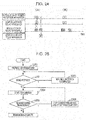
- Fig. 14 is a flowchart illustrating an example of operations performed when the relay apparatus 200 transmits binary data to the power transmission apparatus 100.
- the control parameter is the amount of phase shift in this example, but the following operations also apply when another control parameter is used.
- the relay control circuit 250 determines whether data is being transmitted (step S101). If data is being transmitted, the relay control circuit 250 determines whether the transmission data is 0 (step S102). If the transmission data is 0, the relay control circuit 250 measures the amplitude of the power transmission coil end voltage (step S103) and saves a result of the measurement to the memory (step S14). The measurement and the saving may be performed by the demodulator 280, instead. The relay control circuit 250 then returns to step S101 and performs the same process on next data.
- step S102 if the transmission data is not 0 but 1, the relay control circuit 250 changes the amount of phase shift by a certain value (step S105) and measures the amplitude of the power transmission coil end voltage (step S106). The relay control circuit 250 then determines whether the measured amplitude of the power transmission coil voltage is equal to one at a time when the transmission data is 0 (step S107). If the two amplitudes are not the same, the relay control circuit 250 changes the amount of phase shift in steps of the certain value until the amplitudes become the same. If the two amplitudes are the same, the relay control circuit 250 saves information indicating the amount of phase shift at this time to the memory. The relay control circuit 250 then returns to step S101 and performs the same process on next data.
- the amount of phase shift can enter, using the value saved in the memory, a state in which the amplitude immediately becomes constant when next and later data is transmitted.
- Fig. 15A is a diagram illustrating an example of data (e.g., a packet signal) to be transmitted.
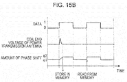
- Fig. 15B is a diagram illustrating temporal changes in the transmission data, the amplitude of the coil end voltage of the power transmission antenna, and the amount of phase shift in a period defined by two broken lines illustrated in Fig. 15A .
- the control circuit 250 adjusts the amount of phase shift through the operations illustrated in Fig. 14 so that the change becomes smaller.
- the amplitude when the transmission data is 1 becomes the same as the amplitude when the transmission data is 0.
- the amount of phase shift at this time is saved to the memory, and the amount of phase shift can be changed next time and later by referring to the value stored in the memory. As a result of these operations, time taken to complete control for making the amplitude of the voltage constant can be reduced.
- Fig. 16 is a diagram illustrating an example of temporal changes in various waveforms according to the present embodiment.
- Fig. 16 illustrates an example of temporal changes in binary transmission data transmitted to a previous stage from the relay apparatus 200, the voltage input to the inverter circuit 230, the amount of phase shift, the voltage input to the power transmission antenna 240, and received data output from the relay demodulator 280.
- the relay apparatus 200 in question is transmitting data to an apparatus in the previous stage, and an apparatus in a subsequent stage is not transmitting data to the relay apparatus 200 in question or the relay apparatus 200 in question is not transmitting data to the apparatus in the subsequent stage.
- the relay control circuit 250 When a value of the transmission data is 1, the amplitude of the voltage of alternating current power input to the rectifier 220 becomes larger than when the value of the transmission data is 0. A value of the direct current voltage input to the inverter circuit 230 from the rectifier 220, therefore, is larger when the value of the transmission data is 1 than when the value of the transmission data is 0.
- the relay control circuit 250 therefore, eliminates a change in the amplitude of the alternating current voltage input to the power transmission antenna 240 from the inverter circuit 230 by changing the amount of phase shift in synchronization with the change in the transmission data. As a result, it is possible to prevent the demodulator 280 from incorrectly receiving data. With the control according to the present embodiment, therefore, the problem of interference described with reference to Fig. 4 can be solved.
- relay apparatuses 200 may be provided between the power transmission apparatus 100 and the power reception apparatus 300, instead.
- Fig. 17 is a diagram illustrating an example of a wireless power transmission system including a plurality of relay apparatuses 200.
- Each relay apparatus 200 have the same configuration as the relay apparatus 200 illustrated in Fig. 3 .
- the power transmission apparatus 100 and the power reception apparatus 300 that are not illustrated in Fig. 17 have the same configurations as those illustrated in Fig. 3 .
- each relay apparatus 200 performs, as described above, control for eliminating variation in the amplitude of the voltage when data is transmitted. As a result, it becomes possible to avoid propagation, to another relay apparatus or the power reception apparatus 300, of an effect of transmission of data from a certain relay apparatus 200.
- Fig. 18 is a diagram illustrating the configuration of a wireless power transmission system according to a second embodiment.
- the wireless power transmission system according to the present embodiment includes, as with the configuration illustrated in Fig. 3 , the power transmission apparatus 100, the relay apparatus 200, and the power reception apparatus 300.
- the present embodiment is different from the first embodiment in that the relay apparatus 200 includes a reverse control circuit 298 that controls the relay amplitude modulator 270 on the basis of received data.
- the reverse control circuit 298 the problem at a time of data reception described with reference to Fig. 5 can be solved.
- the power reception amplitude modulator 370 varies the amplitude of the voltage of alternating current power (power reception alternating current power) received by the power reception power reception antenna 310 between the first amplitude (V1) and the second amplitude (V2).
- binary transmission data power reception transmission data
- the relay demodulator 280 demodulates the binary power reception transmission data on the basis of changes in the voltage of relay alternating current power input to the relay power transmission antenna 240.
- the received data is data generated by demodulating the transmission data and saved to the received data memory 295.
- the relay reverse control circuit 298 reverses a sign of the binary relay received data received by the relay demodulator 280 and causes the relay amplitude modulator 270 to modulate the amplitude of the voltage on the basis of the reversed binary relay received data. More specifically, the relay amplitude modulator 270 performs control for eliminating a difference between a first voltage (DC1) of relay direct current power, which corresponds to the first amplitude (V1), and a second voltage (DC2) of the relay direct current power, which corresponds to the second amplitude (V2). As a result, the variation in the voltage caused by the reception of data from the power reception apparatus 300 is eliminated.
- DC1 first voltage
- DC2 second voltage
- Fig. 19 is a diagram schematically illustrating the above-described operation according to the present embodiment.
- Fig. 19 illustrates an example of temporal changes in received data transmitted from the power reception apparatus 300 to the relay apparatus 200, a reverse modulation signal transmitted from the reverse control circuit 298 to the amplitude modulator 270, the voltage input to the inverter circuit 230 of the relay apparatus 200, a voltage input to the power transmission antenna 140 of the power transmission apparatus 100, and received data output from the demodulator 180 of the power transmission apparatus 100.
- the relay apparatus 200 is only receiving data and is not transmitting data. When the received data is 1, voltage in circuits of the relay apparatus 200 and the power transmission apparatus 100 becomes higher than when the received data is 0.
- the reverse control circuit 298, therefore, transmits a reverse modulation signal, which is obtained by reversing the received data, to the relay amplitude modulator 270.
- the relay amplitude modulator 270 controls the load modulation circuit 275.
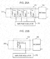
- Fig. 20A is a diagram illustrating an example of the configuration of the load modulation circuit 275 according to the present embodiment.
- the load modulation circuit 275 is connected between the relay power reception antenna 210 and the relay rectifier 220 and includes a plurality of capacitors and a plurality of switches.
- the amplitude modulator 270 determines, on the basis of a reverse modulation signal, a combination of switches for achieving an appropriate load modulation level in order to eliminate the amplitude.
- the reverse modulation signal is a control signal specifying turning on or off of the switches.
- Fig. 20B is a diagram illustrating another example of the configuration of the load modulation circuit 275.
- the load modulation circuit 275 can adjust the load modulation level using variable capacitors.
- the amplitude modulator 270 adjusts, on the basis of a reverse modulation signal, capacitances of the variable capacitors to appropriate values in order to eliminate the load.
- the reverse modulation signal is a signal specifying the capacitances of the variable capacitors and the switch(es) to be turned on.
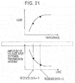
- Fig. 21 indicates a graph schematically illustrating a relationship between a capacitance and a value of a load in the load modulation circuit 275 and a graph schematically illustrating a relationship between the value of the load and the amplitude of an alternating current voltage input to the power transmission power transmission antenna 140.
- the value of the load increases as the capacitance increases, and the amplitude of the alternating current voltage input to the power transmission power transmission antenna 140 decreases as the value of the load increases.
- the reverse control circuit 298, therefore, instructs the amplitude modulator 270 to cancel changes in the amplitude of the voltage caused by load modulation performed in the power reception apparatus 300.
- a lower part of Fig. 21 is a diagram illustrating a state before the instruction is issued.
- the relay apparatus 200 can avoid propagation of an effect to the power transmission apparatus 100 in the previous stage. As a result, independence of data communication can be maintained.
- the reverse control circuit 298, the amplitude modulator 270, and the relay control circuit 250 are separate components in the present embodiment, these components may be achieved by a single circuit (e.g., an MCU), instead. Alternatively, at least a part of these components may be arranged in an apparatus outside the relay apparatus 200.
- a plurality of relay apparatuses 200 may be provided between the power transmission apparatus 100 and the power reception apparatus 300.
- Fig. 22 is a diagram illustrating an example of a wireless power transmission system including a plurality of relay apparatuses 200.
- Each relay apparatus 200 has the same configuration as the relay apparatus 200 illustrated in Fig. 18 .
- the power transmission apparatus 100 and the power reception apparatus 300 that are not illustrated in Fig. 22 have the same configurations as those illustrated in Fig. 18 .
- each relay apparatus 200 performs, as described above, control for eliminating variation in the amplitude of the voltage when data is received. As a result, it becomes possible to avoid propagation, to another relay apparatus or the power transmission apparatus 100, of an effect of transmission of data to a certain relay apparatus 200.
- Fig. 23 is a diagram illustrating a plurality of relay apparatuses 200 according to a third embodiment.
- the relay apparatuses 200 according to the present embodiment are different from those according to the first and second embodiments in that the relay apparatuses 200 according to the present embodiment perform both the control at the time of data transmission according to the first embodiment and the control at the time of data reception according to the second embodiment.
- the relay apparatuses 200 each include a reverse control circuit 298 and performs the reverse control based on received data described in the second embodiment. Furthermore, as described in the first embodiment, the relay control circuit 250 controls the relay inverter circuit 230 on the basis of transmission data. By performing both types of control, an effect upon another apparatus can be suppressed both when data is transmitted and when data is received. The two problems described with reference to Figs. 4 and 5 , therefore, can both be solved.
- Fig. 24 is a diagram illustrating this problem. As illustrated in Fig. 24(A) , when the power reception apparatus 300 transmits data A to a relay apparatus 200, the relay apparatus 200 performs the control employing the amplitude modulator 270 described in the second embodiment and cannot transmit data to a relay apparatus in a previous stage. On the other hand, when the relay apparatus 200 transmits data B to the relay apparatus in the previous stage, the relay apparatus 200 performs the control employing the inverter circuit 230 described in the first embodiment, and the power reception apparatus cannot transmit data to the relay apparatus 200.
- the relay control circuit 250 therefore, transmits a timing control signal instructing the relay amplitude modulator 270 to start to transmit binary transmission data and performs control for avoiding overlapping of a transmission period in which the relay amplitude modulator 270 transmits transmission data and a reception period in which the relay demodulator 280 receives received data.
- timing control in which reception of data from a subsequent stage takes priority over transmission of data to a previous stage is performed. This is because information from a power reception side is more important in terms of stable transmission of power.
- Fig. 24(B) for example, if data A is transmitted from an apparatus in a subsequent stage (the power reception apparatus 300 or another relay apparatus 200) while the relay apparatus 200 is transmitting data B, the transmission of data B stops.
- the transmission of data B is suspended until the transmission of data A is completed.
- Fig. 25 is a flowchart illustrating an example of operations according to the present embodiment.
- the relay control circuit 250 prepares for transmission of data to an apparatus in a previous stage (step S301). At this time, the relay control circuit 250 determines whether data is being received from an apparatus in a subsequent stage (step S302). If data is being received, the relay control circuit 250 waits until the reception is completed (step S303). If data is not being received, the relay control circuit 250 starts the transmission to the apparatus in the previous stage (step S304). The relay control circuit 250 determines as necessary whether data has been received from the apparatus in the subsequent stage during the transmission (step S305). If data has been received, the relay control circuit 250 stops the transmission and waits until the reception is completed (step S306). If data has not been received, the relay control circuit 250 continues and completes the transmission.
- the present disclosure includes wireless power transmission systems and power transmission apparatuses described in the following items.
- the techniques in the present disclosure can be used, for example, in devices necessary to transmit data while supplying power, such as monitoring cameras and robots.
Landscapes
- Engineering & Computer Science (AREA)
- Computer Networks & Wireless Communication (AREA)
- Power Engineering (AREA)
- Signal Processing (AREA)
- Near-Field Transmission Systems (AREA)
- Inverter Devices (AREA)
- Variable-Direction Aerials And Aerial Arrays (AREA)
Description
- The present disclosure relates to a wireless power transmission system that wirelessly transmits power.
- During these years, wireless (noncontact) power transmission techniques for wirelessly (in a noncontact manner) transmitting power to mobile devices such as mobile phones and electric vehicles are being developed.
PTL 1, for example, discloses a noncontact power transmission system that transmits power through magnetic resonance. This system includes a power transmission apparatus and a plurality of power reception apparatuses. It is disclosed that power can be transmitted even to a power reception apparatus outside a reachable range of power from the power transmission apparatus through magnetic resonance between coils of the plurality of power reception apparatuses.PTL 1 also discloses that each power reception apparatus can transmit data to the power transmission apparatus using a method such as amplitude modulation. - PTL 1: Japanese Unexamined Patent Application Publication No.
2010-154592 - There is, however, room for improvement in the existing art in terms of data communication during power transmission.
- In order to solve the above problem, a power transmission apparatus according to an aspect of the present disclosure is
a wireless power transmission system comprising: - a power transmission apparatus;
- a power reception apparatus; and
- a relay apparatus arranged between the power transmission apparatus and the power reception apparatus,
- wherein the power transmission apparatus includes
- a power transmission inverter circuit that converts power transmission direct current power supplied from an external power supply into power transmission alternating current power, and
- a power transmission power transmission antenna that wirelessly transmits the obtained power transmission alternating current power,
- wherein the relay apparatus includes
- a relay power reception antenna that is electromagnetically coupled with the power transmission power transmission antenna and that receives the transmitted power transmission alternating current power,
- a relay rectifier that converts the received power transmission alternating current power into relay direct current power,
- a relay inverter circuit that converts the relay direct current power into relay alternating current power, and
- a relay power transmission antenna that wirelessly transmits the obtained relay alternating current power,
- wherein the power reception apparatus includes
- a power reception power reception antenna that is electromagnetically coupled with the relay power transmission antenna and that receives the transmitted relay alternating current power, and
- wherein the relay apparatus includes
- a relay amplitude modulator that, when the relay apparatus transmits binary relay transmission data to the power transmission apparatus through the electromagnetic coupling between the relay power reception antenna and the power transmission power transmission antenna, varies amplitude of voltage of the power transmission alternating current power received by the relay power reception antenna between a first amplitude (V1) and a second amplitude (V2), and
- a relay control circuit that performs, using the relay inverter circuit, control for eliminating a difference between a third amplitude (V3) of the relay alternating current power, which corresponds to the first amplitude (V1), and a fourth amplitude (V4) of the relay alternating current power, which corresponds to the second amplitude (V2).
- These general or specific aspects may be implemented as a system, a method, an integrated circuit, a computer program, or a recording medium. Alternatively, these general or specific aspects may be implemented as an arbitrary combination of a system, an apparatus, a method, an integrated circuit, a computer program, and a recording medium.
- According to the aspect of the present disclosure, a wireless power transmission system can be achieved that hardly propagates an effect of data communication to another apparatus during power transmission.
-
- [
Fig. 1] Fig. 1 is a diagram illustrating an example of a wireless power transmission system including a plurality of loads. - [
Fig. 2A] Fig. 2A is a block diagram schematically illustrating an example of a wireless power transmission system. - [
Fig. 2B] Fig. 2B is a block diagram schematically illustrating another example of the wireless power transmission system. - [
Fig. 3] Fig. 3 is a block diagram illustrating an example (comparative example) of the configuration ofrelay apparatuses 200 having a function of communicating data through amplitude modulation. - [
Fig. 4] Fig. 4 is a diagram illustrating a problem at a time of data transmission. - [
Fig. 5] Fig. 5 is a diagram illustrating a problem at a time of data reception. - [
Fig. 6] Fig. 6 is a block diagram illustrating the configuration of a wireless power transmission system according to a first embodiment. - [
Fig. 7] Fig. 7 is a diagram illustrating an example of an equivalent circuit of antennas having the configuration of series resonant circuits. - [
Fig. 8A] Fig. 8A is a diagram illustrating an example of the configuration of aload modulation circuit 275. - [
Fig. 8B] Fig. 8B is a diagram illustrating another example of the configuration of theload modulation circuit 275. - [
Fig. 9A] Fig. 9A schematically illustrates the dependence of the amplitude of a voltage at both ends of a coil of a relaypower transmission antenna 240 upon frequency. - [
Fig. 9B] Fig. 9B schematically illustrates the dependence of the amplitude of the voltage at both ends of the coil of the relaypower transmission antenna 240 upon the amount of phase shift. - [
Fig. 9C] Fig. 9C schematically illustrates the dependence of the amplitude of the voltage at both ends of the coil of the relaypower transmission antenna 240 upon a duty ratio. - [
Fig. 9D] Fig. 9D schematically illustrates the dependence of the amplitude of the voltage at both ends of the coil of the relaypower transmission antenna 240 upon a voltage supplied to arelay inverter circuit 230. - [
Fig. 10] Fig. 10 is a diagram illustrating an example of the configuration of therelay inverter circuit 230. - [
Fig. 11A] Fig. 11A is a diagram illustrating amplitude control based on a phase difference between pulse signals. - [
Fig. 11B] Fig. 11B is a diagram illustrating the amplitude control based on the phase difference between the pulse signals. - [
Fig. 12] Fig. 12 is a diagram illustrating another example of the configuration of therelay inverter circuit 230. - [
Fig. 13A] Fig. 13A is a diagram illustrating duty control. - [
Fig. 13B] Fig. 13B is a diagram illustrating the duty control. - [
Fig. 14] Fig. 14 is a flowchart illustrating an example of operations performed when therelay apparatus 200 transmits binary data to apower transmission apparatus 100. - [
Fig. 15A] Fig. 15A is a diagram illustrating an example of data (e.g., a packet signal) to be transmitted. - [
Fig. 15B] Fig. 15B is a diagram illustrating temporal changes in transmission data, the amplitude of a coil end voltage of a power transmission antenna, and the amount of phase shift in a period defined by two broken lines illustrated inFig. 15A . - [
Fig. 16] Fig. 16 is a diagram illustrating an example of temporal changes in various waveforms according to the first embodiment. - [
Fig. 17] Fig. 17 is a diagram illustrating a modification of the first embodiment. - [
Fig. 18] Fig. 18 is a diagram illustrating the configuration of a wireless power transmission system according to a second embodiment. - [
Fig. 19] Fig. 19 is a diagram schematically illustrating an operation according to the second embodiment. - [
Fig. 20A] Fig. 20A is a diagram illustrating an example of the configuration of aload modulation circuit 275 according to the second embodiment. - [
Fig. 20B] Fig. 20B is a diagram illustrating another example of the configuration of theload modulation circuit 275. - [
Fig. 21] Fig. 21 is a diagram indicating a graph schematically illustrating a relationship between a capacitance and a value of a load in theload modulation circuit 275 and a graph schematically illustrating a relationship between the value of the load and the amplitude of an alternating current voltage input to a power transmissionpower transmission antenna 140. - [
Fig. 22] Fig. 22 is a diagram illustrating a modification of the second embodiment. - [
Fig. 23] Fig. 23 is a diagram illustrating a plurality ofrelay apparatuses 200 according to a third embodiment. - [
Fig. 24] Fig. 24 is a diagram illustrating a problem that control at the time of data transmission and control at the time of data reception cannot be performed at the same timing. - [
Fig. 25] Fig. 25 is a flowchart illustrating an example of operations according to the third embodiment. - Underlying knowledge forming the basis of the present disclosure will be described before describing embodiments of the present disclosure.
- The present inventors have examined a wireless power transmission system employing multistage connection (also referred to as "cascade connection"), in which one or more relay apparatuses are provided between a power transmission apparatus and a power reception apparatus and a plurality of loads are driven. Such a wireless power transmission system can be suitably used for a device including a plurality of loads (e.g., motors), such as a robot arm illustrated in
Fig. 1 . In the robot arm illustrated inFig. 1 , a plurality of parts are rotated or moved by motors. Power, therefore, needs to be individually supplied to each motor to control the robot arm. - In such a device including a plurality of movable parts, a power supply supplies, in the existing art, power to loads through a large number of cables. With this configuration, however, there are problems that an accident tends to happen due to cables tangled up together, that a movable range is limited, and that parts cannot be easily replaced. The present inventors, therefore, have attempted to supply power to loads from a power supply through wireless power transmission and eliminate cables extending from the power supply.
-
Fig. 2A is a block diagram schematically illustrating an example of such a wireless power transmission system. In this system, apower transmission apparatus 100 connected to apower supply 50 wirelessly transmits power to apower reception apparatus 300 through a plurality ofrelay apparatuses 200. Each of the plurality ofrelay apparatuses 200 and thepower reception apparatus 300 is connected to aload 400 and supplies a part of the received power to theload 400. Eachrelay apparatus 200 supplies power to theconnected load 400 and transmits power to an apparatus in a subsequent stage (anadjacent relay apparatus 200 or the power reception apparatus 300) in a noncontact manner. It is to be noted that a stage closer to a power transmission apparatus than a relay apparatus in question will be expressed as a "previous stage", and a stage closer to a power reception apparatus than the relay apparatus in question will be expressed as a "next stage" herein. - Power transmission between apparatuses is performed by a power transmission antenna and a power reception antenna. The
power transmission apparatus 100 includes a power transmission antenna, and thepower reception apparatus 300 includes a power reception antenna. Eachrelay apparatus 200 includes both a power reception antenna and a power transmission antenna. Each antenna can be achieved, for example, by a resonant circuit including a coil and a capacitor or a circuit including a pair of electrodes. The former is used for power transmission through magnetic field coupling, and the latter is used for power transmission through electric field coupling. - Each
load 400 is not limited to a motor and can be an arbitrary load such as a camera or a lighting device. Eachload 400 is driven by power from theconnected relay apparatus 200 orpower reception apparatus 300. - Although the system illustrated in
Fig. 2A includes a plurality ofrelay apparatus 200, the number ofrelay apparatuses 200 may be one.Fig. 2B illustrates an example of a wireless power transmission system in which arelay apparatus 200 is provided between apower transmission apparatus 100 and apower reception apparatus 300. - With this configuration, the
power transmission apparatus 100 wirelessly transmits power to thepower reception apparatus 300 through at least onerelay apparatus 200. Power can be individually supplied to eachload 400 without using cables connecting apower supply 50 and a plurality ofloads 400. - In such a wireless power transmission system, information is preferably transmitted between the
power transmission apparatus 100, therelay apparatuses 200, and thepower reception apparatus 300 in order to perform operations safely and stably. For example, information indicating variation in a voltage or power supplied to eachload 400, information specifying stopping of power transmission at a time of occurrence of an abnormality in eachload 400, or the like can be transmitted from each of therelay apparatuses 200 and thepower reception apparatus 300 to an apparatus in a previous stage. Upon receiving the information, the apparatus in the previous stage can adjust a value of power to be transmitted or stop transmitting power. The transmission of information can be performed, for example, using a load modulation method in which a value of a load in a circuit is varied using a switch device. By varying the load and changing the amplitude of voltage in a circuit of an apparatus in a previous stage, information (data) can be transmitted. An example of the transmission of data through amplitude modulation is disclosed, for example, inPTL 1. - The present inventors, however, have found that the following problem arises when data communication through amplitude modulation in the existing art is used in a wireless power transmission system including
relay apparatuses 200. In order to explain the problem, first, an example of the configuration and operation of therelay apparatus 200 will be described. -
Fig. 3 is a block diagram illustrating an example (comparative example) of the configuration ofrelay apparatuses 200 having a function of communicating data through amplitude modulation. As illustrated inFig. 2A , a wireless power transmission system including a plurality ofrelay apparatuses 200 is assumed here. The number ofrelay apparatuses 200 is denoted by N (N is an integer equal to or larger than 2), and theN relay apparatuses 200 sorted as first to N-th relay apparatuses in descending order of closeness to apower transmission apparatus 100 are assumed.Fig. 3 illustrates an (i - 1)th (i = 2 to N) relay apparatus and an i-th relay apparatus among theN relay apparatuses 200. The other relay apparatuses that are not illustrated have the same configuration. - Each
relay apparatus 200 includes apower reception antenna 210, a rectifier (rectifier circuit) 220, aninverter circuit 230, and apower transmission antenna 240. Thepower reception antenna 210 receives alternating current power transmitted from a power transmission antenna of an apparatus in a previous stage (thepower transmission apparatus 100 or another relay apparatus 200). Therectifier 220 converts the alternating current power received by thepower reception antenna 210 into direct current power and outputs the direct current power. A part of the direct current power output from therectifier 220 is supplied to aload 400, and another part is supplied to theinverter circuit 230. Theinverter circuit 230 converts the direct current power output from therectifier 220 into alternating current power and supplies the alternating current power to thepower transmission antenna 240. Thepower transmission antenna 240 transmits the alternating current power to an apparatus in a subsequent stage (anadjacent relay apparatus 200 or the power reception apparatus 300). Theinverter circuit 230 is controlled by acontrol circuit 250 and apulse output circuit 260. - Each
relay apparatus 200 also includes, as components for transmitting data to the apparatus in the previous stage, anamplitude modulator 270 that modulates the amplitude of the voltage of the alternating current power received by thepower reception antenna 210 in accordance with binary transmission data and atransmission data memory 290 storing binary transmission data. Theamplitude modulator 270 modulates the amplitude of the voltage of the alternating current power output from thepower reception antenna 210 by, for example, controlling a switch device in aload modulation circuit 275 connected to therectifier 220. An effect of the modulation is propagated to the apparatus in the previous stage, and data is transmitted. - On the other hand, each
relay apparatus 200 also includes ademodulator 280 as a component for receiving data transmitted from the apparatus in the subsequent stage through the amplitude modulation described above. Thedemodulator 280 reads data transmitted from the apparatus in the subsequent stage by detecting changes in the amplitude of the voltage of the alternating current power output from theinverter circuit 230. The read data is stored in a receiveddata memory 295 as received data. - With this configuration, each
relay apparatus 200 can transmit data to the apparatus in the previous stage and receive data from the apparatus in the subsequent stage. If the amplitude of the alternating current voltage input to theinverter circuit 230 is varied to transmit data to the apparatus in the previous stage, however, a problem arises that an effect of the variation propagates to the alternating current power output from theinverter circuit 230 to thepower transmission antenna 240 and thedemodulator 280 incorrectly receives the data. -
Fig. 4 is a diagram illustrating the problem.Fig. 4 illustrates an example of temporal changes in binary transmission data transmitted from a relay apparatus (e.g., an i-th relay apparatus) 200 to a previous stage, a voltage input to theinverter circuit 230, a voltage input to thepower transmission antenna 240, and received data output from thedemodulator 280. Here, only therelay apparatus 200 in question is transmitting data to an apparatus in the previous stage, and an apparatus in a subsequent stage is not transmitting data to therelay apparatus 200 in question or therelay apparatus 200 in question is not transmitting data to the apparatus in the subsequent stage. - When a value of the transmission data is 0, switches illustrated in
Fig. 8A , which will be described later, are turned on, and when the value of the transmission data is 1, the switches illustrated inFig. 8A , which will be described later, are turned off. When the value of the transmission data is 1, the amplitude of the voltage of alternating current power input to therectifier 220 becomes larger than when the value of the transmission data is 0. A value of the direct current voltage input to theinverter circuit 230 from therectifier 220, therefore, is larger when the value of the transmission data is 1 than when the value of the transmission data is 0. Similarly, an amplitude Va of the alternating current voltage input from theinverter circuit 230 to thepower transmission antenna 240 when the value of the transmission data is 1 is larger than an amplitude Vb when the value of the transmission data is 0. As a result, thedemodulator 280 detects changes in the amplitude although data is not being transmitted from the subsequent stage, and incorrectly receives data. - An effect of the amplitude modulation performed by the
amplitude modulator 270 propagates to arelay apparatus 200 and thepower reception apparatus 300 in a subsequent stage. The above problem of interference, therefore, can occur not only in arelay apparatus 200 that has transmitted data but also in anotherrelay apparatus 200 or thepower reception apparatus 300 in the subsequent stage. That is, while arelay apparatus 200 is transmitting data to an apparatus in a previous stage, not only data communication performed by therelay apparatus 200 but also data communication performed by an apparatus in a subsequent stage is affected. - A similar problem can arise not only when data is transmitted but also when data is received.
-
Fig. 5 is a diagram illustrating a problem at a time of data reception.Fig. 5 illustrates an example of temporal changes in received data transmitted to a certain relay apparatus (e.g., an i-th relay apparatus) 200 from a subsequent stage, a voltage input to theinverter circuit 230 of therelay apparatus 200, a voltage input to the power transmission antenna of an apparatus in a previous stage, and received data output from the demodulator of the apparatus in the previous stage. Here, it is assumed that therelay apparatus 200 is only receiving data and is not transmitting data to the apparatus in the previous stage. When the received data is 1, voltage in therelay apparatus 200 and a circuit of the apparatus in the previous stage is generally higher than when the received data is 0. The direct current voltage input to theinverter circuit 230, therefore, is higher when the received data is 1 than when the received data is 0. Similarly, an amplitude Vd of the alternating current voltage input to the power transmission antenna of the apparatus in the previous stage is higher when the received data is 1 than an amplitude Vc when the received data is 0. - As a result, the demodulator of the apparatus in the previous stage detects the variation between the amplitude Vd and the amplitude Vc and receives the same data. The reception of the same data can also occur in an apparatus in a yet earlier stage, and consequently interferes with data communication performed by the apparatus in the yet earlier stage.
- The present inventors have identified the above two problems that arise when data is transmitted and received and examined a configuration for solving these problems. As a result, the present inventors have found that at least one of the two problems can be solved by introducing, into a relay apparatus, control for eliminating variation in the amplitude of alternating current voltage caused by data communication. Aspects of the present disclosure will be described hereinafter.
- A wireless power transmission system according to an aspect of the present disclosure is
a wireless power transmission system comprising: - a power transmission apparatus;
- a power reception apparatus; and
- a relay apparatus arranged between the power transmission apparatus and the power reception apparatus,
- wherein the power transmission apparatus includes
- a power transmission inverter circuit that converts power transmission direct current power supplied from an external power supply into power transmission alternating current power, and
- a power transmission power transmission antenna that wirelessly transmits the obtained power transmission alternating current power,
- wherein the relay apparatus includes
- a relay power reception antenna that is electromagnetically coupled with the power transmission power transmission antenna and that receives the transmitted power transmission alternating current power,
- a relay rectifier that converts the received power transmission alternating current power into relay direct current power,
- a relay inverter circuit that converts the relay direct current power into relay alternating current power, and
- a relay power transmission antenna that wirelessly transmits the obtained relay alternating current power,
- wherein the power reception apparatus includes
- a power reception power reception antenna that is electromagnetically coupled with the relay power transmission antenna and that receives the transmitted relay alternating current power, and
- wherein the relay apparatus includes
- a relay amplitude modulator that, when the relay apparatus transmits binary relay transmission data to the power transmission apparatus through the electromagnetic coupling between the relay power reception antenna and the power transmission power transmission antenna, varies amplitude of voltage of the power transmission alternating current power received by the relay power reception antenna between a first amplitude (V1) and a second amplitude (V2), and
- a relay control circuit that performs, using the relay inverter circuit, control for eliminating a difference between a third amplitude (V3) of the relay alternating current power, which corresponds to the first amplitude (V1), and a fourth amplitude (V4) of the relay alternating current power, which corresponds to the second amplitude (V2).
- According to the above aspect,
the relay apparatus includes
a relay amplitude modulator that, when the relay apparatus transmits binary relay transmission data to the power transmission apparatus through the electromagnetic coupling between the relay power reception antenna and the power transmission power transmission antenna, varies amplitude of voltage of the power transmission alternating current power received by the relay power reception antenna between a first amplitude (V1) and a second amplitude (V2), and
a relay control circuit that performs, using the relay inverter circuit, control for eliminating a difference between a third amplitude (V3) of the relay alternating current power, which corresponds to the first amplitude (V1), and a fourth amplitude (V4) of the relay alternating current power, which corresponds to the second amplitude (V2). - As a result, even if the relay amplitude modulator is transmitting binary relay transmission data, the amplitude of the relay alternating current power output from the relay inverter circuit hardly varies. The problem of interference described with reference to
Fig. 4 , therefore, can be solved. It is to be noted that "eliminating a difference" does not mean that the difference becomes exactly zero (0), but there may be a slight difference. - A wireless power transmission system according to another aspect of the present disclosure is
a wireless power transmission system comprising: - a power transmission apparatus;
- a power reception apparatus; and
- N (N is an integer equal to or larger than 2) relay apparatuses that are arranged between the power transmission apparatus and the power reception apparatus and that are sorted as first to N-th relay apparatuses in descending order of closeness to the power transmission apparatus,
- wherein the power transmission apparatus includes
- a power transmission inverter circuit that converts power transmission direct current power supplied from an external power supply into power transmission alternating current power, and
- a power transmission power transmission antenna that wirelessly transmits the obtained power transmission alternating current power,
- wherein the first one of the N relay apparatuses includes
- a first relay power reception antenna that is electromagnetically coupled with the power transmission power transmission antenna and that receives the transmitted power transmission alternating current power,
- a first relay rectifier that converts the received power transmission alternating current power into first relay direct current power,
- a first relay inverter circuit that converts the first relay direct current power into first relay alternating current power, and
- a first relay power transmission antenna that wirelessly transmits the obtained first relay alternating current power,
- wherein an i-th (i = 2 to N) one of the N relay apparatuses includes
- an i-th relay power reception antenna that is electromagnetically coupled with an (i - 1)th relay power transmission antenna and that receives the (i - 1)th relay alternating current power,
- an i-th relay rectifier that converts the received (i - 1)th relay alternating current power into i-th relay direct current power,
- an i-th relay inverter circuit that converts the i-th relay direct current power into i-th relay alternating current power, and
- an i-th relay power transmission antenna that wirelessly transmits the obtained i-th relay alternating current power,
- wherein the power reception apparatus includes
- a power reception power reception antenna that is electromagnetically coupled with the N-th relay power transmission antenna and that receives the N-th relay alternating current power, and
- wherein the i-th (i = 2 to N) relay apparatus includes
- an i-th relay amplitude modulator that, when the i-th relay apparatus transmits binary i-th relay transmission data to the (i - 1)th relay apparatus through the electromagnetic coupling between the i-th relay power reception antenna and the (i - 1)th relay power transmission antenna, varies amplitude of voltage of the (i - 1)th relay alternating current power received by the i-th relay power reception antenna between a first amplitude (V1) and a second amplitude (V2), and
- an i-th relay control circuit that performs, using the i-th relay inverter circuit, control for eliminating a difference between a third amplitude (V3) of the i-th relay alternating current power, which corresponds to the first amplitude (V1), and a fourth amplitude (V4) of the i-th relay alternating current power, which corresponds to the second amplitude (V2),
- According to the above aspect,
the i-th (i = 2 to N) relay apparatus includes
an i-th relay amplitude modulator that, when the i-th relay apparatus transmits binary i-th relay transmission data to the (i - 1)th relay apparatus through the electromagnetic coupling between the i-th relay power reception antenna and the (i - 1)th relay power transmission antenna, varies amplitude of voltage of the (i - 1)th relay alternating current power received by the i-th relay power reception antenna between a first amplitude (V1) and a second amplitude (V2), and
an i-th relay control circuit that performs, using the i-th relay inverter circuit, control for eliminating a difference between a third amplitude (V3) of the i-th relay alternating current power, which corresponds to the first amplitude (V1), and a fourth amplitude (V4) of the i-th relay alternating current power, which corresponds to the second amplitude (V2). - As a result, even if the i-th relay amplitude modulator is transmitting the binary i-th relay transmission data in the wireless power transmission system including the plurality of relay apparatuses, the amplitude of the relay alternating current power output from the i-th relay inverter circuit hardly varies. The problem of interference described with reference to
Fig. 4 , therefore, can be solved. - A wireless power transmission system according to yet another aspect of the present disclosure is
a wireless power transmission system comprising: - a power transmission apparatus;
- a power reception apparatus; and
- a relay apparatus arranged between the power transmission apparatus and the power reception apparatus,
- wherein the power transmission apparatus includes
- a power transmission inverter circuit that converts power transmission direct current power supplied from an external power supply into power transmission alternating current power, and
- a power transmission power transmission antenna that wirelessly transmits the obtained power transmission alternating current power,
- wherein the relay apparatus includes
- a relay power reception antenna that is electromagnetically coupled with the power transmission power transmission antenna and that receives the transmitted power transmission alternating current power,
- a relay rectifier that converts the received power transmission alternating current power into relay direct current power,
- a relay inverter circuit that converts the relay direct current power into relay alternating current power, and
- a relay power transmission antenna that wirelessly transmits the obtained relay alternating current power,
- wherein the power reception apparatus includes
- a power reception power reception antenna that is electromagnetically coupled with the relay power transmission antenna and that receives the transmitted relay alternating current power,
- a power reception rectifier that converts the relay alternating current power received by the power reception power reception antenna into power reception direct current power, and
- a power reception amplitude modulator that transmits binary power reception transmission data to the relay apparatus through the electromagnetic coupling between the power reception power reception antenna and the relay power reception antenna by varying amplitude of voltage of the relay alternating current power received by the power reception power reception antenna between a first amplitude (V1) and a second amplitude (V2), and
- wherein the relay apparatus also includes
- a relay demodulator that is connected to the relay power transmission antenna and that receives binary relay received data by demodulating the binary power reception transmission data on the basis of a change in the voltage of the relay alternating current power input to the relay power transmission antenna, and
- a relay reverse control circuit that reverses a sign of the binary relay received data received by the relay demodulator and that performs, using the relay amplitude modulator, control for eliminating a difference between a first voltage (DC1) of the relay direct current power, which corresponds to the first amplitude (V1), and a second voltage (DC2) of the relay direct current power, which corresponds to the second amplitude (V2), on the basis of the reversed binary relay received data.
- According to the above aspect,
the relay apparatus includes
a relay demodulator that is connected to the relay power transmission antenna and that receives binary relay received data by demodulating the binary power reception transmission data on the basis of a change in the voltage of the relay alternating current power input to the relay power transmission antenna, and
a relay reverse control circuit that reverses a sign of the binary relay received data received by the relay demodulator and that performs, using the relay amplitude modulator, control for eliminating a difference between a first voltage (DC1) of the relay direct current power, which corresponds to the first amplitude (V1), and a second voltage (DC2) of the relay direct current power, which corresponds to the second amplitude (V2), on the basis of the reversed binary relay received data. - As a result, the difference between the first voltage (DC1) and the second voltage (DC2) of the relay direct current power when the power reception amplitude modulator is transmitting data the power reception transmission data can be almost perfectly eliminated. The unnecessary reception of data by an apparatus in a previous stage described with reference to
Fig. 5 , therefore, can be prevented. - A wireless power transmission system according to yet another aspect of the present disclosure is
a wireless power transmission system comprising: - a power transmission apparatus;
- a power reception apparatus; and
- N (N is an integer equal to or larger than 2) relay apparatuses that are arranged between the power transmission apparatus and the power reception apparatus and that are sorted as first to N-th relay apparatuses in descending order of closeness to the power transmission apparatus,
- wherein the power transmission apparatus includes
- a power transmission inverter circuit that converts power transmission direct current power supplied from an external power supply into power transmission alternating current power, and
- a power transmission power transmission antenna that wirelessly transmits the obtained power transmission alternating current power,
- wherein the first one of the N relay apparatuses includes
- a first relay power reception antenna that is electromagnetically coupled with the power transmission power transmission antenna and that receives the transmitted power transmission alternating current power,
- a first relay rectifier that converts the received power transmission alternating current power into first relay direct current power,
- a first relay inverter circuit that converts the first relay direct current power into first relay alternating current power, and
- a first relay power transmission antenna that wirelessly transmits the obtained first relay alternating current power,
- wherein an i-th (i = 2 to N) one of the N relay apparatuses includes
- an i-th relay power reception antenna that is electromagnetically coupled with an (i - 1)th relay power transmission antenna and that receives the (i - 1)th relay alternating current power,
- an i-th relay rectifier that converts the received (i - 1)th relay alternating current power into i-th relay direct current power,
- an i-th relay inverter circuit that converts the i-th relay direct current power into i-th relay alternating current power, and
- an i-th relay power transmission antenna that wirelessly transmits the obtained i-th relay alternating current power,
- wherein the power reception apparatus includes
- a power reception power reception antenna that is electromagnetically coupled with the N-th relay power transmission antenna and that receives the N-th relay alternating current power, and
- a power reception rectifier that converts the N-th relay alternating current power received by the power reception power reception antenna into power reception direct current power, and
- wherein the first relay apparatus also includes
- a first relay amplitude modulator that transmits binary first relay transmission data to the power transmission apparatus through electromagnetic coupling between the first relay power reception antenna and the power transmission power transmission antenna by varying amplitude of voltage of the power transmission alternating current power received by the first relay power reception antenna between a first first amplitude (V1) and a first second voltage (V2),
- wherein the i-th (i = 2 to N) relay apparatus also includes
- an i-th relay amplitude modulator that transmits binary i-th relay transmission data to the (i - 1)th relay apparatus through electromagnetic coupling between the i-th relay power reception antenna and the (i - 1)th relay power transmission antenna by varying amplitude of voltage of the (i - 1)th relay alternating current power received by the i-th relay power reception antenna between an i-th first amplitude (V1) and an i-th second amplitude (V2), and
- wherein the (i - 1)th (i = 2 to N) relay apparatus also includes
- an (i - 1)th relay demodulator that is connected to the (i - 1)th relay power transmission antenna and that receives binary (i - 1)th relay received data by demodulating the binary i-th relay transmission data on the basis of a change in the voltage of the (i - 1)th relay alternating current power input to the (i - 1)th relay power transmission antenna, and
- an (i - 1)th relay reverse control circuit that reverses a sign of the binary (i - 1)th relay received data received by the (i - 1)th relay demodulator and that performs, using the (i - 1)th relay amplitude modulator, control for eliminating a difference between a first voltage (DC1) of the (i - 1)th relay direct current power, which corresponds to the i-th first amplitude (V1), and a second voltage (DC2) of the (i - 1)th relay direct current power, which corresponds to the i-th second amplitude (V2), on the basis of the reversed binary (i - 1)th relay received data.
- According to the above aspect,
the (i - 1)th (i = 2 to N) relay apparatus includes
an (i - 1)th relay demodulator that is connected to the (i - 1)th relay power transmission antenna and that receives binary (i - 1)th relay received data by demodulating the binary i-th relay transmission data on the basis of a change in the voltage of the (i - 1)th relay alternating current power input to the (i - 1)th relay power transmission antenna, and
an (i - 1)th relay reverse control circuit that reverses a sign of the binary (i - 1)th relay received data received by the (i - 1)th relay demodulator and that performs, using the (i - 1)th relay amplitude modulator, control for eliminating a difference between a first voltage (DC1) of the (i - 1)th relay direct current power, which corresponds to the i-th first amplitude (V1), and a second voltage (DC2) of the (i - 1)th relay direct current power, which corresponds to the i-th second amplitude (V2), on the basis of the reversed binary (i - 1)th relay received data. - As a result, the difference between the first voltage (DC1) and the second voltage (DC2) of the relay direct current power when a certain relay apparatus is receiving data from an apparatus in a subsequent stage in the wireless power transmission system including the plurality of relay apparatuses can be almost perfectly eliminated. The unnecessary reception of data by an apparatus in a previous stage described with reference to
Fig. 5 , therefore, can be prevented. - More specific embodiments of the present disclosure will be described hereinafter. Unnecessarily detailed description, however, might be omitted. For example, detailed description of well-known matters and redundant description of substantially the same components might be omitted. This is in order to prevent the following description from becoming unnecessarily redundant and facilitate understanding by those skilled in the art. It is to be noted that the present inventors provide the accompanying drawings and the following description in order to help those skilled in the art fully understand the present disclosure and do not intend to limit the theme described in the claims. In the following description, the same or similar components are given the same reference numerals.
- It is to be noted that expressions "power transmission...", "relay...", and "power reception..." will be used herein for terms relating to a power transmission apparatus, a relay apparatus, and a power reception apparatus, respectively, to facilitate understanding. The terms "power transmission", "relay", and "power reception" might be omitted for the sake of simplicity.
-
Fig. 6 is a block diagram illustrating the configuration of a wireless power transmission system according to a first embodiment of the present disclosure. The wireless power transmission system includes apower transmission apparatus 100, arelay apparatus 200, and apower reception apparatus 300. The present system corresponds to the configuration illustrated inFig. 2B and includes onerelay apparatus 200. - The
relay apparatus 200 according to the present embodiment has the same configuration as therelay apparatus 200 described with reference toFig. 3 , but the operation of arelay control circuit 250 is different from that described above. When arelay amplitude modulator 270 transmits data to thepower transmission apparatus 100, therelay control circuit 250 according to the present embodiment controls arelay inverter circuit 230 such that the amplitude of the voltage of alternating current power output from theinverter circuit 230 does not vary. As a result, therelay apparatus 200 can correctly receive data from thepower reception apparatus 300 even while therelay apparatus 200 is transmitting data. - The
power transmission apparatus 100 includes a powertransmission inverter circuit 130 that converts direct current power input from an external direct current (DC)power supply 50 into alternating current power and that outputs the alternating current power and a power transmissionpower transmission antenna 140 that transmits the alternating current power output from the powertransmission inverter circuit 130. Thepower transmission apparatus 100 also includes apulse output circuit 160 that drives the powertransmission inverter circuit 130, a powertransmission control circuit 150 that controls thepulse output circuit 160, apower transmission demodulator 180 that demodulates data transmitted from therelay apparatus 200, and a receiveddata memory 195. - The
relay apparatus 200 is electromagnetically coupled with the power transmissionpower transmission antenna 140 and includes a relaypower reception antenna 240 that receives transmitted alternating current power (power transmission alternating current power), arelay rectifier 220 that converts the received power transmission alternating current power into direct current power (relay direct current power), therelay inverter circuit 230 that converts the relay direct current power into alternating current power (relay alternating current power), and a relaypower transmission antenna 240 that wirelessly transmits the obtained relay alternating current power. Therelay apparatus 200 also includes aload modulation circuit 275 connected between thepower reception antenna 210 and therectifier 220, therelay amplitude modulator 270 that changes a value of a load of theload modulation circuit 275 in accordance with values of transmission data, and atransmission data memory 290 storing the transmission data. Therelay apparatus 200 also includes apulse output circuit 260 that supplies pulse signals to a plurality of switching elements included in therelay inverter circuit 230, therelay control circuit 250 that controls thepulse output circuit 260, arelay demodulator 280 that receives data by detecting changes in the amplitude of an alternating current voltage applied to thepower transmission antenna 240, and a receiveddata memory 295 storing the received data. - The
power reception apparatus 300 includes a power receptionpower reception antenna 310 that receives relay alternating current power transmitted from the relaypower transmission antenna 240 and apower reception rectifier 320 that converts the alternating current power received by thepower reception antenna 310 into direct current power (power reception direct current power) and that outputs the direct current power. Thepower reception apparatus 300 also includes aload modulation circuit 375 connected between thepower reception antenna 310 and therectifier 320, a powerreception amplitude modulator 370 that controls theload modulation circuit 375 in such a way as to modulate the amplitude of the alternating current power received by thepower reception antenna 310, and atransmission data memory 390 storing data to be transmitted to therelay apparatus 200. - The power transmission
power transmission antenna 140, the relaypower reception antenna 210, the relaypower transmission antenna 240, and the power receptionpower reception antenna 310 can each be achieved, for example, by a resonant circuit including a coil and a capacitor.Fig. 7 illustrates an example of an equivalent circuit of theantennas - The
power reception apparatus 300 can be, for example, a tip of a robot arm, a rotation unit of a monitoring camera, or the like. Thepower transmission apparatus 100 is an apparatus that wirelessly supplies power to therelay apparatus 200 and can be mounted, for example, on a root of the robot arm or a fixing unit of the monitoring camera. Therelay apparatus 200 can be, for example, a component connecting the root and the tip of the robot arm or a component connecting the fixing unit and the rotation unit of the monitoring camera. Aload 400 can be, for example, a device including a motor, such as an actuator, mounted on the tip of the robot arm or an image capture device, such as a CCD camera, mounted on the rotation unit of the monitoring camera. Theload 400 is connected to therelay rectifier 220 and thepower reception rectifier 320 and driven by direct current power. - With this configuration, the wireless power transmission system according to the present embodiment can communicate data between adjacent apparatuses while wirelessly transmitting power. A type of data to be transmitted can be, for example, information indicating a power value or a voltage in a circuit, a control signal or a signal indicating an abnormality from a connected load, or the like. The transmission data may be a response signal to an instruction or image (video) data.
-
Fig. 8A is a diagram illustrating an example of the configuration of theload modulation circuit 275. The illustratedload modulation circuit 275 is connected between thepower reception antenna 210 and therectifier 220. Theload modulation circuit 275 includes two switches and two capacitors connected parallel to thepower reception antenna 210 and a resistor connected between a point between the two capacitors and the ground. Theload modulation circuit 275 performs load modulation by switching open/close states of the two switches on the basis of controls signals from theamplitude modulator 270. More specifically, theload modulation circuit 275 changes a value of an overall load thereof by switching on/off states of the two switches and opening or closing a current route different from a route to theload 400. As a result, information can be transmitted to thepower transmission apparatus 100. - Although the
load modulation circuit 275 is arranged in a previous stage of therectifier 220 in the example illustrated inFig. 6 , theload modulation circuit 275 may be arranged in a subsequent stage of therectifier 220, instead.Fig. 8B is a diagram illustrating an example of theload modulation circuit 275 arranged in this manner. Theload modulation circuit 275 is connected between therectifier 220 and theload 400. Theload modulation circuit 275 includes a resistor and a switch connected parallel to therectifier 220. Theload modulation circuit 275 can change an overall load of the power reception apparatus by switching an on/off state of the switch on the basis of a control signal from theamplitude modulator 270. - Although
Figs. 8A and 8B illustrate an example the configuration of therelay amplitude modulator 270 and the relayload modulation circuit 275, the powerreception amplitude modulator 370 and the power receptionload modulation circuit 375 have the same configuration. - The power
transmission inverter circuit 130 and therelay inverter circuit 230 convert supplied direct current power into alternating current power using a plurality of switching elements. In order to control theinverter circuits pulse output circuits control circuits transmission control circuit 150 and therelay control circuit 250 are each achieved, for example, by an integrated circuit including a processor such as a microcontroller (MCU). Thepulse output circuits control circuits - The power
transmission control circuit 150 and therelay control circuit 250 control pulse signals input to the switching elements from thepulse output circuits power transmission demodulator 180 and therelay demodulator 280, respectively. As a result, the frequency and amplitude of the alternating current power output from theinverter circuits - The power transmission parameter is a parameter for controlling timings at which the plurality of switching elements included in each inverter circuit are turned on (conductive state) and off (nonconductive state). The power transmission parameter can be the frequency of a pulse signal input to each switching element, a phase difference (also referred to as the "amount of phase shift") between two pulse signals input to two switching elements that are simultaneously turned on among the plurality of switching elements, a duty ratio of the pulse signal input to each switching element, or the like.
-
Figs. 9A to 9D schematically illustrate the dependence of the amplitude of a voltage (also referred to as a coil end voltage) at both ends of the coil included in the relaypower transmission antenna 240 upon the frequency, the amount of phase shift, the duty ratio, and a voltage supplied to therelay inverter circuit 230, respectively. As illustrated inFig. 9A , when the frequency is increased, the amplitude of the coil end voltage tends to decrease. As illustrated inFig. 9B , when the amount of phase shift is increased within a range of 0° to 180°, the amplitude of the coil end voltage decreases. As illustrated inFig. 9C , when the duty ratio is increased within a range of 0% to 50%, the amplitude of the coil end voltage increases. As illustrated inFig. 9D , when the voltage supplied to therelay inverter circuit 230 is increased, the amplitude of the coil end voltage increases. Therelay control circuit 250, therefore, can control the amplitude of the coil end voltage using at least any of the frequency, the amount of phase shift, the duty ratio, and the supplied voltage as a control parameter. It is to be noted that the voltage supplied to theinverter circuit 230 can be controlled when a DC-DC converter is provided between therelay rectifier 220 and therelay inverter circuit 230. With this configuration, therelay control circuit 250 can adjust a value of a voltage output from the DC-DC converter by changing the frequency of switching of switching elements included in the DC-DC converter. -
Fig. 10 is a diagram illustrating an example of therelay inverter circuit 230. Theinverter circuit 230 includes a plurality of switching elements S1 to S4 whose conductive/nonconductive states change in accordance with pulse signals supplied from thepulse output circuit 260. By changing the conductive/nonconductive state of each switching element, input direct current power can be converted into alternating current power. In the example illustrated inFig. 10 , a full-bridge inverter circuit including the four switching elements S1 to S4 is used. In this example, each switching element is an IGBT (Insulated-gate bipolar transistor), but a switching element of another type, such as a MOSFET (Metal Oxide Semiconductor Field-Effect Transistor) may be used, instead. - In the example illustrated in
Fig. 10 , among the four switching elements S1 to S4, the switching elements S1 and S4 (first switching element pair) output, when conductive, a voltage having the same polarity as a supplied direct current voltage. On the other hand, the switching elements S2 and S3 (second switching element pair) output, when conductive, a voltage having an opposite polarity to the supplied direct current voltage. Thepulse output circuit 260 supplies pulse signals to gates of the switching elements S1 to S4 in accordance with an instruction from thecontrol circuit 250. At this time, thepulse output circuit 260 can perform amplitude control by adjusting a phase difference between the two pulse signals supplied to the first switching element pair (S1 and S4) and a phase difference between the two pulse signals supplied to the second switching element pair (S2 and S3). -
Figs. 11A and 11B are diagrams illustrating the amplitude control based on the phase differences between the pulse signals.Fig. 11A schematically illustrates temporal changes in the four pulse signals and a voltage V output from theinverter circuit 230 at a time when an amount ϕ of phase shift between the two pulse signals supplied to the switching elements S1 and S4 and the amount ϕ of phase shift between the two pulse signals supplied to the switching elements S2 and S3 are 0 degree.Fig. 11B schematically illustrates temporal changes in the pulse signals and the voltage V at a time when the amount ϕ of phase shift is 90 degrees. The amount ϕ of phase shift is adjusted by temporally shifting rising and falling timings of the pulse signals input to the switching elements S3 and S4 relative to rising and falling timings of the pulse signals input to the switching elements S1 and S2. If the amount ϕ of phase shift is changed, an output time ratio (a ratio of a period in which the voltage V is not zero to one cycle) changes. The output time ratio of the voltage Va becomes higher as the amount ϕ of phase shift becomes closer to 0 degree, and becomes lower as the amount ϕ of phase shift becomes closer to 180 degrees. The voltage V output from theinverter circuit 230 can be converted into a sine-wave voltage by a smoothing circuit that is not illustrated and supplied to thepower transmission antenna 240. The amplitude of the sine-wave voltage changes in accordance with the output time ratio. By changing the amount ϕ of phase shift, therefore, the amplitude of the alternating current voltage input to thepower transmission antenna 240 can be changed. -
Fig. 12 is a diagram illustrating another example of the configuration of therelay inverter circuit 230. Theinverter circuit 230 in this example is a half-bridge inverter circuit. When a half-bridge inverter circuit is used, the above-described phase control cannot be applied. In this case, the amplitude of the voltage can be controlled by controlling the duty ratio of the pulse signal input to each switching element. The half-bridge inverter circuit illustrated inFig. 12 , which will be described later, is a circuit that controls the duty ratio. In contrast toFig. 12 , the full-bridge inverter circuit illustrated inFig. 10 is a circuit that controls the amount ϕ of phase shift. Compared to a half-bridge inverter circuit, a full-bridge inverter circuit can reduce generation of noise in alternating current power input to thepower transmission antenna 240. - The
inverter circuit 230 illustrated inFig. 12 is a half-bridge inverter circuit including two switching elements S1 and S2 and two capacitors. The two switching elements S1 and S2 and two capacitors C1 and C2 are connected parallel to each other. One end of thepower transmission antenna 240 is connected to a point between the two switching elements S1 and S2, and another end is connected to a point between the two capacitors C1 and C2. - The
control circuit 250 and thepulse output circuit 260 supply a pulse signal to each switching element such that the switching elements S1 and S2 alternately turn on. As a result, direct current power is converted into alternating current power. - In this example, the output time ratio of the output voltage V can be adjusted by adjusting the duty ratio (that is, a ratio of a period in which the pulse signal is on to one cycle) of the pulse signals. As a result, the amplitude of the voltage of the alternating current power input to the
power transmission antenna 240 can be adjusted. -
Figs. 13A and13B are diagrams illustrating the duty control.Fig. 13A illustrates an example of waveforms of the pulse signals input to the switching elements S1 to S4 and the output voltage V at a time when the duty ratio of each pulse signal is 0.5 (50%).Fig. 13B illustrates an example of waveforms of the pulse signals input to the switching elements S1 to S4 and the output voltage V at a time when the duty ratio of each pulse signal is 0.25 (25%). As illustrated in the figures, by changing the duty ratio, the output time ratio (that is, a period in which the voltage V is not zero to one cycle) of the voltage V can be changed. As a result, the amplitude of the smoothed voltage of transmission power, too, can be changed. Such pulse signals whose duty ratios are different from each other are generated, for example, by thepulse output circuit 260 including a PWM control circuit. The duty ratio is adjusted within a range of 0% to 50%. When the duty ratio is 50%, the amplitude of the voltage of transmission power becomes largest, and when the duty ratio is 0%, the amplitude of the voltage of transmission power becomes smallest. The duty control can also be applied when the full-bridge inverter circuit illustrated inFig. 10 is used. - It is to be noted that although a method for controlling the
relay inverter circuit 230 has been described in the above example, the same type of control can also be applied to the powertransmission inverter circuit 130. - Next, the control according to the present embodiment will be described more specifically.
- The
relay control circuit 250 according to the present embodiment performs control for suppressing variation in the amplitude of the voltage output from therelay inverter circuit 230 caused when therelay amplitude modulator 270 modulates the amplitude to transmit data. More specifically, therelay control circuit 250 changes a value of a control parameter used in synchronization with timings at which therelay amplitude modulator 270 changes the amplitude of the voltage between two values (a first amplitude V1 and a second amplitude V2). The value of the control parameter is determined such that a difference between the amplitude (third amplitude V3) of relay alternating current power corresponding to the first amplitude V1 and the amplitude (fourth amplitude V4) of relay alternating current power corresponding to the second amplitude V2 becomes close to 0. Such a control parameter can be determined, for example, on the basis of a voltage detected by therelay demodulator 280. -
Fig. 14 is a flowchart illustrating an example of operations performed when therelay apparatus 200 transmits binary data to thepower transmission apparatus 100. The control parameter is the amount of phase shift in this example, but the following operations also apply when another control parameter is used. - First, the
relay control circuit 250 determines whether data is being transmitted (step S101). If data is being transmitted, therelay control circuit 250 determines whether the transmission data is 0 (step S102). If the transmission data is 0, therelay control circuit 250 measures the amplitude of the power transmission coil end voltage (step S103) and saves a result of the measurement to the memory (step S14). The measurement and the saving may be performed by thedemodulator 280, instead. Therelay control circuit 250 then returns to step S101 and performs the same process on next data. - In step S102, if the transmission data is not 0 but 1, the
relay control circuit 250 changes the amount of phase shift by a certain value (step S105) and measures the amplitude of the power transmission coil end voltage (step S106). Therelay control circuit 250 then determines whether the measured amplitude of the power transmission coil voltage is equal to one at a time when the transmission data is 0 (step S107). If the two amplitudes are not the same, therelay control circuit 250 changes the amount of phase shift in steps of the certain value until the amplitudes become the same. If the two amplitudes are the same, therelay control circuit 250 saves information indicating the amount of phase shift at this time to the memory. Therelay control circuit 250 then returns to step S101 and performs the same process on next data. - As described above, by saving the control parameter to the memory, the amount of phase shift can enter, using the value saved in the memory, a state in which the amplitude immediately becomes constant when next and later data is transmitted.
-
Fig. 15A is a diagram illustrating an example of data (e.g., a packet signal) to be transmitted.Fig. 15B is a diagram illustrating temporal changes in the transmission data, the amplitude of the coil end voltage of the power transmission antenna, and the amount of phase shift in a period defined by two broken lines illustrated inFig. 15A . When the transmission data changes from 0 to 1, the amplitude of the voltage changes. Thecontrol circuit 250 adjusts the amount of phase shift through the operations illustrated inFig. 14 so that the change becomes smaller. As a result, the amplitude when the transmission data is 1 becomes the same as the amplitude when the transmission data is 0. The amount of phase shift at this time is saved to the memory, and the amount of phase shift can be changed next time and later by referring to the value stored in the memory. As a result of these operations, time taken to complete control for making the amplitude of the voltage constant can be reduced. -
Fig. 16 is a diagram illustrating an example of temporal changes in various waveforms according to the present embodiment.Fig. 16 illustrates an example of temporal changes in binary transmission data transmitted to a previous stage from therelay apparatus 200, the voltage input to theinverter circuit 230, the amount of phase shift, the voltage input to thepower transmission antenna 240, and received data output from therelay demodulator 280. Here, only therelay apparatus 200 in question is transmitting data to an apparatus in the previous stage, and an apparatus in a subsequent stage is not transmitting data to therelay apparatus 200 in question or therelay apparatus 200 in question is not transmitting data to the apparatus in the subsequent stage. When a value of the transmission data is 1, the amplitude of the voltage of alternating current power input to therectifier 220 becomes larger than when the value of the transmission data is 0. A value of the direct current voltage input to theinverter circuit 230 from therectifier 220, therefore, is larger when the value of the transmission data is 1 than when the value of the transmission data is 0. Therelay control circuit 250 according to the present embodiment, therefore, eliminates a change in the amplitude of the alternating current voltage input to thepower transmission antenna 240 from theinverter circuit 230 by changing the amount of phase shift in synchronization with the change in the transmission data. As a result, it is possible to prevent the demodulator 280 from incorrectly receiving data. With the control according to the present embodiment, therefore, the problem of interference described with reference toFig. 4 can be solved. - It is to be noted that although the number of
relay apparatuses 200 is one in the present embodiment, a plurality ofrelay apparatuses 200 may be provided between thepower transmission apparatus 100 and thepower reception apparatus 300, instead. -
Fig. 17 is a diagram illustrating an example of a wireless power transmission system including a plurality ofrelay apparatuses 200. InFig. 17 , an (i - 1)th (i = 2 to N) relay apparatus and an i-th relay apparatus among N (N is an integer equal to or larger than 2) are illustrated. Eachrelay apparatus 200 have the same configuration as therelay apparatus 200 illustrated inFig. 3 . In addition, thepower transmission apparatus 100 and thepower reception apparatus 300 that are not illustrated inFig. 17 have the same configurations as those illustrated inFig. 3 . - The
relay control circuit 250 of eachrelay apparatus 200 performs, as described above, control for eliminating variation in the amplitude of the voltage when data is transmitted. As a result, it becomes possible to avoid propagation, to another relay apparatus or thepower reception apparatus 300, of an effect of transmission of data from acertain relay apparatus 200. -
Fig. 18 is a diagram illustrating the configuration of a wireless power transmission system according to a second embodiment. The wireless power transmission system according to the present embodiment includes, as with the configuration illustrated inFig. 3 , thepower transmission apparatus 100, therelay apparatus 200, and thepower reception apparatus 300. The present embodiment is different from the first embodiment in that therelay apparatus 200 includes areverse control circuit 298 that controls therelay amplitude modulator 270 on the basis of received data. By providing thereverse control circuit 298, the problem at a time of data reception described with reference toFig. 5 can be solved. - In the present embodiment, the power
reception amplitude modulator 370 varies the amplitude of the voltage of alternating current power (power reception alternating current power) received by the power receptionpower reception antenna 310 between the first amplitude (V1) and the second amplitude (V2). As a result, binary transmission data (power reception transmission data) is transmitted to therelay apparatus 200 through electromagnetic coupling between the power receptionpower reception antenna 310 and the relaypower transmission antenna 240. Therelay demodulator 280 demodulates the binary power reception transmission data on the basis of changes in the voltage of relay alternating current power input to the relaypower transmission antenna 240. Here, the received data is data generated by demodulating the transmission data and saved to the receiveddata memory 295. - The relay
reverse control circuit 298 reverses a sign of the binary relay received data received by therelay demodulator 280 and causes therelay amplitude modulator 270 to modulate the amplitude of the voltage on the basis of the reversed binary relay received data. More specifically, therelay amplitude modulator 270 performs control for eliminating a difference between a first voltage (DC1) of relay direct current power, which corresponds to the first amplitude (V1), and a second voltage (DC2) of the relay direct current power, which corresponds to the second amplitude (V2). As a result, the variation in the voltage caused by the reception of data from thepower reception apparatus 300 is eliminated. -
Fig. 19 is a diagram schematically illustrating the above-described operation according to the present embodiment.Fig. 19 illustrates an example of temporal changes in received data transmitted from thepower reception apparatus 300 to therelay apparatus 200, a reverse modulation signal transmitted from thereverse control circuit 298 to theamplitude modulator 270, the voltage input to theinverter circuit 230 of therelay apparatus 200, a voltage input to thepower transmission antenna 140 of thepower transmission apparatus 100, and received data output from thedemodulator 180 of thepower transmission apparatus 100. Here, therelay apparatus 200 is only receiving data and is not transmitting data. When the received data is 1, voltage in circuits of therelay apparatus 200 and thepower transmission apparatus 100 becomes higher than when the received data is 0. Thereverse control circuit 298, therefore, transmits a reverse modulation signal, which is obtained by reversing the received data, to therelay amplitude modulator 270. Upon receiving the reverse modulation signal, therelay amplitude modulator 270 controls theload modulation circuit 275. As a result, variation in the direct current voltage input to therelay inverter circuit 230 is eliminated. Consequently, variation in the amplitude of the alternating current voltage input to thepower transmission antenna 140 of thepower transmission apparatus 100 is also eliminated. It is therefore possible to avoid reception, by thepower transmission demodulator 180, of the same data as relay received data. - The control performed by the
amplitude modulator 270 and theload modulation circuit 275 will be described more specifically hereinafter. -
Fig. 20A is a diagram illustrating an example of the configuration of theload modulation circuit 275 according to the present embodiment. Theload modulation circuit 275 is connected between the relaypower reception antenna 210 and therelay rectifier 220 and includes a plurality of capacitors and a plurality of switches. Theamplitude modulator 270 determines, on the basis of a reverse modulation signal, a combination of switches for achieving an appropriate load modulation level in order to eliminate the amplitude. The reverse modulation signal is a control signal specifying turning on or off of the switches. -
Fig. 20B is a diagram illustrating another example of the configuration of theload modulation circuit 275. Theload modulation circuit 275 can adjust the load modulation level using variable capacitors. Theamplitude modulator 270 adjusts, on the basis of a reverse modulation signal, capacitances of the variable capacitors to appropriate values in order to eliminate the load. In this example, the reverse modulation signal is a signal specifying the capacitances of the variable capacitors and the switch(es) to be turned on. -
Fig. 21 indicates a graph schematically illustrating a relationship between a capacitance and a value of a load in theload modulation circuit 275 and a graph schematically illustrating a relationship between the value of the load and the amplitude of an alternating current voltage input to the power transmissionpower transmission antenna 140. As illustrated in the figure, the value of the load increases as the capacitance increases, and the amplitude of the alternating current voltage input to the power transmissionpower transmission antenna 140 decreases as the value of the load increases. Thereverse control circuit 298, therefore, instructs theamplitude modulator 270 to cancel changes in the amplitude of the voltage caused by load modulation performed in thepower reception apparatus 300. Upon receiving the instruction, theamplitude modulator 270 cancels the changes in the amplitude of the voltage by relatively increasing the value of the load when the received data is 1, by relatively decreasing the value of the load when the received data is 0, or by performing both. It is to be noted that a lower part ofFig. 21 is a diagram illustrating a state before the instruction is issued. - As a result of the above operation, when the
power reception apparatus 300 transmits data to therelay apparatus 200 through amplitude modulation, therelay apparatus 200 can avoid propagation of an effect to thepower transmission apparatus 100 in the previous stage. As a result, independence of data communication can be maintained. - It is to be noted that although the
reverse control circuit 298, theamplitude modulator 270, and therelay control circuit 250 are separate components in the present embodiment, these components may be achieved by a single circuit (e.g., an MCU), instead. Alternatively, at least a part of these components may be arranged in an apparatus outside therelay apparatus 200. - In the present embodiment, too, a plurality of
relay apparatuses 200 may be provided between thepower transmission apparatus 100 and thepower reception apparatus 300.Fig. 22 is a diagram illustrating an example of a wireless power transmission system including a plurality ofrelay apparatuses 200. InFig. 22 , an (i - 1)th (i = 2 to N) relay apparatus and an i-th relay apparatus among N (N is an integer equal to or larger than 2) relay apparatuses are illustrated. Eachrelay apparatus 200 has the same configuration as therelay apparatus 200 illustrated inFig. 18 . In addition, thepower transmission apparatus 100 and thepower reception apparatus 300 that are not illustrated inFig. 22 have the same configurations as those illustrated inFig. 18 . - The
reverse control circuit 298 of eachrelay apparatus 200 performs, as described above, control for eliminating variation in the amplitude of the voltage when data is received. As a result, it becomes possible to avoid propagation, to another relay apparatus or thepower transmission apparatus 100, of an effect of transmission of data to acertain relay apparatus 200. -
Fig. 23 is a diagram illustrating a plurality ofrelay apparatuses 200 according to a third embodiment. The relay apparatuses 200 according to the present embodiment are different from those according to the first and second embodiments in that therelay apparatuses 200 according to the present embodiment perform both the control at the time of data transmission according to the first embodiment and the control at the time of data reception according to the second embodiment. - As illustrated in
Fig. 23 , therelay apparatuses 200 according to the present embodiment each include areverse control circuit 298 and performs the reverse control based on received data described in the second embodiment. Furthermore, as described in the first embodiment, therelay control circuit 250 controls therelay inverter circuit 230 on the basis of transmission data. By performing both types of control, an effect upon another apparatus can be suppressed both when data is transmitted and when data is received. The two problems described with reference toFigs. 4 and5 , therefore, can both be solved. - Although the
relay apparatuses 200 according to the present embodiment perform both the control at the time of data transmission and the control at the time of data reception, therelay apparatuses 200 cannot perform both types of control at the same timing.Fig. 24 is a diagram illustrating this problem. As illustrated inFig. 24(A) , when thepower reception apparatus 300 transmits data A to arelay apparatus 200, therelay apparatus 200 performs the control employing theamplitude modulator 270 described in the second embodiment and cannot transmit data to a relay apparatus in a previous stage. On the other hand, when therelay apparatus 200 transmits data B to the relay apparatus in the previous stage, therelay apparatus 200 performs the control employing theinverter circuit 230 described in the first embodiment, and the power reception apparatus cannot transmit data to therelay apparatus 200. - The
relay control circuit 250 according to the present embodiment, therefore, transmits a timing control signal instructing therelay amplitude modulator 270 to start to transmit binary transmission data and performs control for avoiding overlapping of a transmission period in which therelay amplitude modulator 270 transmits transmission data and a reception period in which therelay demodulator 280 receives received data. - In the present embodiment, timing control in which reception of data from a subsequent stage takes priority over transmission of data to a previous stage is performed. This is because information from a power reception side is more important in terms of stable transmission of power. As illustrated in
Fig. 24(B) , for example, if data A is transmitted from an apparatus in a subsequent stage (thepower reception apparatus 300 or another relay apparatus 200) while therelay apparatus 200 is transmitting data B, the transmission of data B stops. In addition, if data B is to be transmitted while data A is being transmitted from the apparatus in the subsequent stage, the transmission of data B is suspended until the transmission of data A is completed. -
Fig. 25 is a flowchart illustrating an example of operations according to the present embodiment. First, therelay control circuit 250 prepares for transmission of data to an apparatus in a previous stage (step S301). At this time, therelay control circuit 250 determines whether data is being received from an apparatus in a subsequent stage (step S302). If data is being received, therelay control circuit 250 waits until the reception is completed (step S303). If data is not being received, therelay control circuit 250 starts the transmission to the apparatus in the previous stage (step S304). Therelay control circuit 250 determines as necessary whether data has been received from the apparatus in the subsequent stage during the transmission (step S305). If data has been received, therelay control circuit 250 stops the transmission and waits until the reception is completed (step S306). If data has not been received, therelay control circuit 250 continues and completes the transmission. - As a result of the above operations, interference between data transmission and data reception is prevented, and preferable communication in which reception of data from a subsequent stage takes priority can be achieved.
- As described above, the present disclosure includes wireless power transmission systems and power transmission apparatuses described in the following items.
- [Item 1] A wireless power transmission system comprising:
- a power transmission apparatus;
- a power reception apparatus; and
- a relay apparatus arranged between the power transmission apparatus and the power reception apparatus,
- wherein the power transmission apparatus includes
- a power transmission inverter circuit that converts power transmission direct current power supplied from an external power supply into power transmission alternating current power, and
- a power transmission power transmission antenna that wirelessly transmits the obtained power transmission alternating current power,
- wherein the relay apparatus includes
- a relay power reception antenna that is electromagnetically coupled with the power transmission power transmission antenna and that receives the transmitted power transmission alternating current power,
- a relay rectifier that converts the received power transmission alternating current power into relay direct current power,
- a relay inverter circuit that converts the relay direct current power into relay alternating current power, and
- a relay power transmission antenna that wirelessly transmits the obtained relay alternating current power,
- wherein the power reception apparatus includes
- a power reception power reception antenna that is electromagnetically coupled with the relay power transmission antenna and that receives the transmitted relay alternating current power, and
- wherein the relay apparatus includes
- a relay amplitude modulator that, when the relay apparatus transmits binary relay transmission data to the power transmission apparatus through the electromagnetic coupling between the relay power reception antenna and the power transmission power transmission antenna, varies amplitude of voltage of the power transmission alternating current power received by the relay power reception antenna between a first amplitude (V1) and a second amplitude (V2), and
- a relay control circuit that performs, using the relay inverter circuit, control for eliminating a difference between a third amplitude (V3) of the relay alternating current power, which corresponds to the first amplitude (V1), and a fourth amplitude (V4) of the relay alternating current power, which corresponds to the second amplitude (V2).
- [Item 2] The wireless power transmission system according to
Item 1,
wherein the binary relay transmission data is transmission data representing a power value of the relay direct current power. - [Item 3] The wireless power transmission system according to
Item
wherein the power reception apparatus includes
a power reception rectifier that converts the relay alternating current power received by the power reception power reception antenna into power reception direct current power, and
a power reception amplitude modulator that transmits binary power reception transmission data to the relay apparatus through the electromagnetic coupling between the power reception power reception antenna and the relay power reception antenna, and
wherein the power transmission apparatus includes
a power transmission demodulator that is connected to the power transmission power transmission antenna and that demodulates the binary relay transmission data on the basis of a change in voltage of the power transmission alternating current power input to the power transmission power transmission antenna. - [Item 4] The wireless power transmission system according to
Item 3,
wherein the binary power reception transmission data is transmission data representing a power value of the power reception direct current power. - [Item 5] A wireless power transmission system comprising:
- a power transmission apparatus;
- a power reception apparatus; and
- N (N is an integer equal to or larger than 2) relay apparatuses that are arranged between the power transmission apparatus and the power reception apparatus and that are sorted as first to N-th relay apparatuses in descending order of closeness to the power transmission apparatus,
- wherein the power transmission apparatus includes
- a power transmission inverter circuit that converts power transmission direct current power supplied from an external power supply into power transmission alternating current power, and
- a power transmission power transmission antenna that wirelessly transmits the obtained power transmission alternating current power,
- wherein the first one of the N relay apparatuses includes
- a first relay power reception antenna that is electromagnetically coupled with the power transmission power transmission antenna and that receives the transmitted power transmission alternating current power,
- a first relay rectifier that converts the received power transmission alternating current power into first relay direct current power,
- a first relay inverter circuit that converts the first relay direct current power into first relay alternating current power, and
- a first relay power transmission antenna that wirelessly transmits the obtained first relay alternating current power,
- wherein an i-th (i = 2 to N) one of the N relay apparatuses includes
- an i-th relay power reception antenna that is electromagnetically coupled with an (i - 1)th relay power transmission antenna and that receives the (i - 1)th relay alternating current power,
- an i-th relay rectifier that converts the received (i - 1)th relay alternating current power into i-th relay direct current power,
- an i-th relay inverter circuit that converts the i-th relay direct current power into i-th relay alternating current power, and
- an i-th relay power transmission antenna that wirelessly transmits the obtained i-th relay alternating current power,
- wherein the power reception apparatus includes
- a power reception power reception antenna that is electromagnetically coupled with the N-th relay power transmission antenna and that receives the N-th relay alternating current power, and
- wherein the i-th (i = 2 to N) relay apparatus includes
- an i-th relay amplitude modulator that, when the i-th relay apparatus transmits binary i-th relay transmission data to the (i - 1)th relay apparatus through the electromagnetic coupling between the i-th relay power reception antenna and the (i - 1)th relay power transmission antenna, varies amplitude of voltage of the (i - 1)th relay alternating current power received by the i-th relay power reception antenna between a first amplitude (V1) and a second amplitude (V2), and
- an i-th relay control circuit that performs, using the i-th relay inverter circuit, control for eliminating a difference between a third amplitude (V3) of the i-th relay alternating current power, which corresponds to the first amplitude (V1), and a fourth amplitude (V4) of the i-th relay alternating current power, which corresponds to the second amplitude (V2).
- [Item 6] The wireless power transmission system according to
Item 5,
wherein the binary i-th (i = 2 to N) relay transmission data is transmission data representing a power value of the i-th relay direct current power. - [Item 7] The wireless power transmission system according to
Item 5 or 6,
wherein the power reception apparatus includes
a power reception rectifier that converts the N-th relay alternating current power received by the power reception power reception antenna into power reception direct current power, and
a power reception amplitude modulator that transmits binary power reception transmission data to the N-th relay apparatus through the electromagnetic coupling between the power reception power reception antenna and the N-th relay power transmission antenna,
wherein the N-th relay apparatus includes
an N-th relay demodulator that is connected to the N-th relay power transmission antenna and that demodulates the binary power reception transmission data on the basis of a change in voltage of the N-th relay alternating current power input to the N-th relay power transmission antenna, and
wherein the (i - 1)th (i = 2 to N) relay apparatus includes
an (i - 1)th relay demodulator that is connected to the (i - 1)th relay power transmission antenna and that demodulates the binary i-th relay transmission data on the basis of a change in the voltage of the (i - 1)th relay alternating current power input to the (i - 1)th relay power transmission antenna. - [Item 8] The wireless power transmission system according to Item 7,
wherein the binary power reception transmission data is transmission data representing a power value of the power reception direct current power. - [Item 9] The wireless power transmission system according to any of
Items 5 to 8,
wherein the first relay apparatus further includes
a first relay amplitude modulator that, when the first relay apparatus transmits binary first relay transmission data to the power transmission apparatus through the electromagnetic coupling between the first relay power reception antenna and the power transmission power transmission antenna, varies amplitude of voltage of the first relay direct current power received by the first relay power reception antenna between a fifth amplitude (V5) and a sixth amplitude (V6), and
a first relay control circuit that performs, using the first relay inverter circuit, control for eliminating a difference between a seventh amplitude (V7) of the first relay alternating current power, which corresponds to the fifth amplitude (V5), and an eighth amplitude (V8) of the first relay alternating current power, which corresponds to the sixth amplitude (V6), and
wherein the power transmission apparatus includes
a power transmission demodulator that is connected to the power transmission power transmission antenna and that demodulates the binary first relay transmission data on the basis of voltage of the power transmission alternating current power input to the power transmission power transmission antenna. - [Item 10] The wireless power transmission system according to Item 9,
wherein the binary first relay transmission data is transmission data representing a power value of the first relay direct current power. - [Item 11] The wireless power transmission system according to
Item 7 or 8,
wherein the i-th (i = 2 to N) relay amplitude modulator varies amplitude of the voltage of the (i - 1)th relay alternating current power received by the i-th relay power reception antenna between a ninth amplitude (W9) and a tenth amplitude (W10) by detecting the power value of the i-th relay direct current power output from the i-th relay rectifier and transmitting the binary i-th relay transmission data representing the power value of the i-th relay direct current power to the (i - 1)th relay apparatus through the electromagnetic coupling between the i-th relay power reception antenna and the (i - 1)th relay power transmission antenna,
wherein the (i - 1)th (i = 2 to N) relay demodulator demodulates the binary i-th relay transmission data transmitted from the i-th relay apparatus and receives binary (i - 1)th relay received data on the basis of the demodulated binary i-th relay transmission data,
wherein the (i - 1)th (i = 2 to N) relay apparatus includes
an (i - 1)th relay reverse control circuit that reverses a sign of the binary (i - 1)th relay received data received by the (i - 1)th relay demodulator and that performs, using the (i - 1)th relay amplitude modulator, control for eliminating a difference between a first voltage (DC1) of the (i - 1)th relay direct current power, which corresponds to the ninth amplitude (W9), and a second voltage (DC2) of the (i - 1)th relay direct current power, which corresponds to the tenth amplitude (W10), on the basis of the reversed binary (i - 1)th relay received data,
wherein the power reception amplitude modulator varies amplitude of the voltage of the N-th relay alternating current power received by the power reception power reception antenna between an eleventh amplitude (W11) and a twelfth amplitude (W12) by detecting the power value of the power reception direct current power output from the power reception rectifier and transmitting the binary power reception transmission data representing the power value of the power reception direct current power to the N-th relay apparatus through the electromagnetic coupling between the power reception power reception antenna and the N-th relay power transmission antenna,
wherein the N-th relay demodulator demodulates the binary power reception transmission data transmitted from the power reception apparatus and receives binary N-th relay received data on the basis of the demodulated binary power reception transmission data,
wherein the N-th relay apparatus includes
an N-th relay reverse control circuit that reverses a sign of the binary N-th relay received data received by the N-th relay demodulator and that performs, using the N-th relay amplitude modulator, control for eliminating a difference between a third voltage (DC3) of the N-th relay direct current power, which corresponds to the eleventh amplitude (W11), and a fourth voltage (DC4) of the N-th relay direct current power, which corresponds to the twelfth amplitude (W12), on the basis of the reversed binary N-th relay received data, and
wherein the i-th (i = 2 to N) relay control circuit transmits a first timing control signal for instructing the i-th relay amplitude modulator to start to transmit the binary i-th relay transmission data and performs control for avoiding overlapping of a transmission period in which the i-th relay amplitude modulator transmits the i-th relay transmission data and a reception period in which the i-th relay demodulator receives the binary i-th relay received data.
According to the above aspects, the problem of interference at the time of data transmission described with reference toFig. 4 and the problem of interference at the time of data reception described with reference toFig. 5 can both be solved. - [Item 12] The wireless power transmission system according to Item 11,
wherein, when the i-th relay demodulator receives the i-th relay received data while the i-th relay amplitude modulator is transmitting the binary i-th relay transmission data, the i-th (i = 2 to N) relay control circuit stops the transmission of the binary i-th relay transmission data performed by the i-th relay amplitude modulator and gives priority to generation of the i-th relay received data. - [Item 13] The wireless power transmission system according to Item 12,
wherein, when the reception of the binary i-th relay received data has been completed, the i-th relay control circuit causes the i-th power reception amplitude modulator to resume the transmission of the i-th relay transmission data. - [Item 14] The wireless power transmission system according to any of
Items 5 to 13, further comprising:- a memory,
- wherein the i-th (i = 2 to N) relay control circuit
- saves, after the control for eliminating the difference between the third amplitude (V3) of the i-th relay alternating current power and the fourth amplitude (V4) of the i-th relay alternating current power is performed using the i-th relay inverter circuit, a control parameter corresponding to the difference between the third amplitude (V3) and the fourth amplitude (V4) to the memory, and
- controls, when the control for eliminating the difference between the third amplitude (V3) and the fourth amplitude (V4) is to be performed next time, the i-th relay inverter circuit using the control parameter saved in the memory.
- [Item 15] The wireless power transmission system according to any of
Items 5 to 14,
wherein the i-th (i = 2 to N) relay inverter circuit includes four switching elements,
wherein the four switching elements include a first switching element pair that, when conductive, outputs a voltage having the same polarity as voltage of the supplied i-th relay direct current power and a second switching element pair that, when conductive, outputs a voltage having an opposite polarity to the voltage of the first direct current power, and
wherein the i-th relay control circuit
supplies a pulse signal for switching a conductive and nonconductive state to each of the four switching elements, and
performs the control for eliminating the difference between the third amplitude (V3) and the fourth amplitude (V4) by adjusting a phase difference between two pulse signals supplied to the first switching element pair and a phase difference between two pulse signals supplied to the second switching element pair. - [Item 16] The wireless power transmission system according to any of
Items 5 to 14,
wherein the i-th (i = 2 to N) relay control circuit performs the control for eliminating the difference between the third amplitude (V3) and the fourth amplitude (V4) by changing frequency of the i-th relay alternating current power output from the i-th relay inverter circuit. - [Item 17] The wireless power transmission system according to any of
Items 5 to 14,
wherein the i-th (i = 2 to N) relay inverter circuit includes a plurality of switching elements, and
wherein the i-th (i = 2 to N) relay control circuit
supplies a pulse signal for switching a conductive and nonconductive state to each of the plurality of switching elements, and
performs the control for eliminating the difference between the third amplitude (V3) and the fourth amplitude (V4) by adjusting a duty ratio of the pulse signal. - The techniques in the present disclosure can be used, for example, in devices necessary to transmit data while supplying power, such as monitoring cameras and robots.
-
- 50 direct current (DC) power supply
- 100 power transmission apparatus
- 130 power transmission inverter circuit
- 140 power transmission power transmission antenna
- 150 power transmission control circuit
- 160 pulse output circuit
- 180 power transmission demodulator
- 195 received data memory
- 200 relay apparatus
- 210 relay power reception antenna
- 220 relay rectifier
- 230 relay inverter circuit
- 240 relay power transmission antenna
- 250 relay control circuit
- 260
pulse output circuit 260 - 270 relay amplitude modulator
- 275 relay load modulation circuit
- 280 relay demodulator
- 290 transmission data memory
- 295 received data memory
- 298 reverse control circuit
- 300 power reception apparatus
- 310 power reception power reception antenna
- 320 power reception rectifier
- 370 power reception amplitude modulator
- 375 power reception load modulation circuit
- 390 transmission data memory
- 400 load
Claims (17)
- A wireless power transmission system comprising:a power transmission apparatus;a power reception apparatus; anda relay apparatus arranged between the power transmission apparatus and the power reception apparatus,wherein the power transmission apparatus includesa power transmission inverter circuit that converts power transmission direct current power supplied from an external power supply into power transmission alternating current power, anda power transmission power transmission antenna that wirelessly transmits the obtained power transmission alternating current power,wherein the relay apparatus includesa relay power reception antenna that is electromagnetically coupled with the power transmission power transmission antenna and that receives the transmitted power transmission alternating current power,a relay rectifier that converts the received power transmission alternating current power into relay direct current power,a relay inverter circuit that converts the relay direct current power into relay alternating current power, anda relay power transmission antenna that wirelessly transmits the obtained relay alternating current power,wherein the power reception apparatus includesa power reception power reception antenna that is electromagnetically coupled with the relay power transmission antenna and that receives the transmitted relay alternating current power, andwherein the relay apparatus includesa relay amplitude modulator that, when the relay apparatus transmits binary relay transmission data to the power transmission apparatus through the electromagnetic coupling between the relay power reception antenna and the power transmission power transmission antenna, varies amplitude of voltage of the power transmission alternating current power received by the relay power reception antenna between a first amplitude (V1) and a second amplitude (V2), anda relay control circuit that performs, using the relay inverter circuit, control for eliminating a difference between a third amplitude (V3) of the relay alternating current power, which corresponds to the first amplitude (V1), and a fourth amplitude (V4) of the relay alternating current power, which corresponds to the second amplitude (V2).
- The wireless power transmission system according to Claim 1,
wherein the binary relay transmission data is transmission data representing a power value of the relay direct current power. - The wireless power transmission system according to Claim 1 or 2,
wherein the power reception apparatus includes
a power reception rectifier that converts the relay alternating current power received by the power reception power reception antenna into power reception direct current power, and
a power reception amplitude modulator that transmits binary power reception transmission data to the relay apparatus through the electromagnetic coupling between the power reception power reception antenna and the relay power reception antenna, and
wherein the power transmission apparatus includes
a power transmission demodulator that is connected to the power transmission power transmission antenna and that demodulates the binary relay transmission data on the basis of a change in voltage of the power transmission alternating current power input to the power transmission power transmission antenna. - The wireless power transmission system according to Claim 3,
wherein the binary power reception transmission data is transmission data representing a power value of the power reception direct current power. - A wireless power transmission system comprising:a power transmission apparatus;a power reception apparatus; andN (N is an integer equal to or larger than 2) relay apparatuses that are arranged between the power transmission apparatus and the power reception apparatus and that are sorted as first to N-th relay apparatuses in descending order of closeness to the power transmission apparatus,wherein the power transmission apparatus includesa power transmission inverter circuit that converts power transmission direct current power supplied from an external power supply into power transmission alternating current power, anda power transmission power transmission antenna that wirelessly transmits the obtained power transmission alternating current power,wherein the first one of the N relay apparatuses includesa first relay power reception antenna that is electromagnetically coupled with the power transmission power transmission antenna and that receives the transmitted power transmission alternating current power,a first relay rectifier that converts the received power transmission alternating current power into first relay direct current power,a first relay inverter circuit that converts the first relay direct current power into first relay alternating current power, anda first relay power transmission antenna that wirelessly transmits the obtained first relay alternating current power,wherein an i-th (i = 2 to N) one of the N relay apparatuses includesan i-th relay power reception antenna that is electromagnetically coupled with an (i - 1)th relay power transmission antenna and that receives the (i - 1)th relay alternating current power,an i-th relay rectifier that converts the received (i - 1)th relay alternating current power into i-th relay direct current power,an i-th relay inverter circuit that converts the i-th relay direct current power into i-th relay alternating current power, andan i-th relay power transmission antenna that wirelessly transmits the obtained i-th relay alternating current power,wherein the power reception apparatus includesa power reception power reception antenna that is electromagnetically coupled with the N-th relay power transmission antenna and that receives the N-th relay alternating current power, andwherein the i-th (i = 2 to N) relay apparatus includesan i-th relay amplitude modulator that, when the i-th relay apparatus transmits binary i-th relay transmission data to the (i - 1)th relay apparatus through the electromagnetic coupling between the i-th relay power reception antenna and the (i - 1)th relay power transmission antenna, varies amplitude of voltage of the (i - 1)th relay alternating current power received by the i-th relay power reception antenna between a first amplitude (V1) and a second amplitude (V2), andan i-th relay control circuit that performs, using the i-th relay inverter circuit, control for eliminating a difference between a third amplitude (V3) of the i-th relay alternating current power, which corresponds to the first amplitude (V1), and a fourth amplitude (V4) of the i-th relay alternating current power, which corresponds to the second amplitude (V2).
- The wireless power transmission system according to Claim 5,
wherein the binary i-th (i = 2 to N) relay transmission data is transmission data representing a power value of the i-th relay direct current power. - The wireless power transmission system according to Claim 5 or 6,
wherein the power reception apparatus includes
a power reception rectifier that converts the N-th relay alternating current power received by the power reception power reception antenna into power reception direct current power, and
a power reception amplitude modulator that transmits binary power reception transmission data to the N-th relay apparatus through the electromagnetic coupling between the power reception power reception antenna and the N-th relay power transmission antenna,
wherein the N-th relay apparatus includes
an N-th relay demodulator that is connected to the N-th relay power transmission antenna and that demodulates the binary power reception transmission data on the basis of a change in voltage of the N-th relay alternating current power input to the N-th relay power transmission antenna, and
wherein the (i - 1)th (i = 2 to N) relay apparatus includes
an (i - 1)th relay demodulator that is connected to the (i - 1)th relay power transmission antenna and that demodulates the binary i-th relay transmission data on the basis of a change in the voltage of the (i - 1)th relay alternating current power input to the (i - 1)th relay power transmission antenna. - The wireless power transmission system according to Claim 7,
wherein the binary power reception transmission data is transmission data representing a power value of the power reception direct current power. - The wireless power transmission system according to any of Claims 5 to 8,
wherein the first relay apparatus further includes
a first relay amplitude modulator that, when the first relay apparatus transmits binary first relay transmission data to the power transmission apparatus through the electromagnetic coupling between the first relay power reception antenna and the power transmission power transmission antenna, varies amplitude of voltage of the first relay direct current power received by the first relay power reception antenna between a fifth amplitude (V5) and a sixth amplitude (V6), and
a first relay control circuit that performs, using the first relay inverter circuit, control for eliminating a difference between a seventh amplitude (V7) of the first relay alternating current power, which corresponds to the fifth amplitude (V5), and an eighth amplitude (V8) of the first relay alternating current power, which corresponds to the sixth amplitude (V6), and
wherein the power transmission apparatus includes
a power transmission demodulator that is connected to the power transmission power transmission antenna and that demodulates the binary first relay transmission data on the basis of voltage of the power transmission alternating current power input to the power transmission power transmission antenna. - The wireless power transmission system according to Claim 9,
wherein the binary first relay transmission data is transmission data representing a power value of the first relay direct current power. - The wireless power transmission system according to Claim 7 or 8,
wherein the i-th (i = 2 to N) relay amplitude modulator varies amplitude of the voltage of the (i - 1)th relay alternating current power received by the i-th relay power reception antenna between a ninth amplitude (W9) and a tenth amplitude (W10) by detecting the power value of the i-th relay direct current power output from the i-th relay rectifier and transmitting the binary i-th relay transmission data representing the power value of the i-th relay direct current power to the (i - 1)th relay apparatus through the electromagnetic coupling between the i-th relay power reception antenna and the (i - 1)th relay power transmission antenna,
wherein the (i - 1)th (i = 2 to N) relay demodulator demodulates the binary i-th relay transmission data transmitted from the i-th relay apparatus and receives binary (i - 1)th relay received data on the basis of the demodulated binary i-th relay transmission data,
wherein the (i - 1)th (i = 2 to N) relay apparatus includes
an (i - 1)th relay reverse control circuit that reverses a sign of the binary (i - 1)th relay received data received by the (i - 1)th relay demodulator and that performs, using the (i - 1)th relay amplitude modulator, control for eliminating a difference between a first voltage (DC1) of the (i - 1)th relay direct current power, which corresponds to the ninth amplitude (W9), and a second voltage (DC2) of the (i - 1)th relay direct current power, which corresponds to the tenth amplitude (W10), on the basis of the reversed binary (i - 1)th relay received data,
wherein the power reception amplitude modulator varies amplitude of the voltage of the N-th relay alternating current power received by the power reception power reception antenna between an eleventh amplitude (W11) and a twelfth amplitude (W12) by detecting the power value of the power reception direct current power output from the power reception rectifier and transmitting the binary power reception transmission data representing the power value of the power reception direct current power to the N-th relay apparatus through the electromagnetic coupling between the power reception power reception antenna and the N-th relay power transmission antenna,
wherein the N-th relay demodulator demodulates the binary power reception transmission data transmitted from the power reception apparatus and receives binary N-th relay received data on the basis of the demodulated binary power reception transmission data,
wherein the N-th relay apparatus includes
an N-th relay reverse control circuit that reverses a sign of the binary N-th relay received data received by the N-th relay demodulator and that performs, using the N-th relay amplitude modulator, control for eliminating a difference between a third voltage (DC3) of the N-th relay direct current power, which corresponds to the eleventh amplitude (W11), and a fourth voltage (DC4) of the N-th relay direct current power, which corresponds to the twelfth amplitude (W12), on the basis of the reversed binary N-th relay received data, and
wherein the i-th (i = 2 to N) relay control circuit transmits a first timing control signal for instructing the i-th relay amplitude modulator to start to transmit the binary i-th relay transmission data and performs control for avoiding overlapping of a transmission period in which the i-th relay amplitude modulator transmits the i-th relay transmission data and a reception period in which the i-th relay demodulator receives the binary i-th relay received data. - The wireless power transmission system according to Claim 11,
wherein, when the i-th relay demodulator receives the i-th relay received data while the i-th relay amplitude modulator is transmitting the binary i-th relay transmission data, the i-th (i = 2 to N) relay control circuit stops the transmission of the binary i-th relay transmission data performed by the i-th relay amplitude modulator and gives priority to generation of the i-th relay received data. - The wireless power transmission system according to Claim 12,
wherein, when the reception of the binary i-th relay received data has been completed, the i-th relay control circuit causes the i-th power reception amplitude modulator to resume the transmission of the i-th relay transmission data. - The wireless power transmission system according to any of Claims 5 to 13, further comprising:a memory,wherein the i-th (i = 2 to N) relay control circuitsaves, after the control for eliminating the difference between the third amplitude (V3) of the i-th relay alternating current power and the fourth amplitude (V4) of the i-th relay alternating current power is performed using the i-th relay inverter circuit, a control parameter corresponding to the difference between the third amplitude (V3) and the fourth amplitude (V4) to the memory, andcontrols, when the control for eliminating the difference between the third amplitude (V3) and the fourth amplitude (V4) is to be performed next time, the i-th relay inverter circuit using the control parameter saved in the memory.
- The wireless power transmission system according to any of Claims 5 to 14,
wherein the i-th (i = 2 to N) relay inverter circuit includes four switching elements,
wherein the four switching elements include a first switching element pair that, when conductive, outputs a voltage having the same polarity as voltage of the supplied i-th relay direct current power and a second switching element pair that, when conductive, outputs a voltage having an opposite polarity to the voltage of the first direct current power, and
wherein the i-th relay control circuit
supplies a pulse signal for switching a conductive and nonconductive state to each of the four switching elements, and
performs the control for eliminating the difference between the third amplitude (V3) and the fourth amplitude (V4) by adjusting a phase difference between two pulse signals supplied to the first switching element pair and a phase difference between two pulse signals supplied to the second switching element pair. - The wireless power transmission system according to any of Claims 5 to 14,
wherein the i-th (i = 2 to N) relay control circuit performs the control for eliminating the difference between the third amplitude (V3) and the fourth amplitude (V4) by changing frequency of the i-th relay alternating current power output from the i-th relay inverter circuit. - The wireless power transmission system according to any of Claims 5 to 14,
wherein the i-th (i = 2 to N) relay inverter circuit includes a plurality of switching elements, and
wherein the i-th (i = 2 to N) relay control circuit
supplies a pulse signal for switching a conductive and nonconductive state to each of the plurality of switching elements, and
performs the control for eliminating the difference between the third amplitude (V3) and the fourth amplitude (V4) by adjusting a duty ratio of the pulse signal.
Applications Claiming Priority (3)
| Application Number | Priority Date | Filing Date | Title |
|---|---|---|---|
| JP2015196731 | 2015-10-02 | ||
| JP2016125423A JP6120116B2 (en) | 2015-10-02 | 2016-06-24 | Wireless power transmission system |
| PCT/JP2016/003181 WO2017056352A1 (en) | 2015-10-02 | 2016-07-04 | Wireless power transmission system |
Publications (3)
| Publication Number | Publication Date |
|---|---|
| EP3358711A4 EP3358711A4 (en) | 2018-08-08 |
| EP3358711A1 true EP3358711A1 (en) | 2018-08-08 |
| EP3358711B1 EP3358711B1 (en) | 2019-09-04 |
Family
ID=58495506
Family Applications (1)
| Application Number | Title | Priority Date | Filing Date |
|---|---|---|---|
| EP16850539.4A Active EP3358711B1 (en) | 2015-10-02 | 2016-07-04 | Wireless power transmission system |
Country Status (4)
| Country | Link |
|---|---|
| US (2) | US10411521B2 (en) |
| EP (1) | EP3358711B1 (en) |
| JP (2) | JP6120116B2 (en) |
| CN (1) | CN107078559B (en) |
Families Citing this family (14)
| Publication number | Priority date | Publication date | Assignee | Title |
|---|---|---|---|---|
| JP6167395B2 (en) * | 2013-03-22 | 2017-07-26 | パナソニックIpマネジメント株式会社 | Power supply device |
| KR101847256B1 (en) * | 2016-01-11 | 2018-05-28 | 한국전자통신연구원 | Wireless power receiver, system having the same and method for controlling automatically load resistance transformation ratio |
| DE102016120254A1 (en) * | 2016-10-24 | 2018-04-26 | Endress+Hauser Conducta Gmbh+Co. Kg | Circuit for supplying energy to a consumer and for receiving user signals transmitted by the consumer |
| JP2019117993A (en) * | 2017-12-27 | 2019-07-18 | 日本無線株式会社 | Radio control device and radio control system |
| US10659036B2 (en) * | 2018-02-27 | 2020-05-19 | The Florida State University Research Foundation, Inc. | Radio-frequency isolated gate driver for power semiconductors |
| CN108539820B (en) * | 2018-04-26 | 2021-01-26 | 华东交通大学 | Charging system based on wireless charging |
| KR102608558B1 (en) * | 2018-11-15 | 2023-11-30 | 엘지전자 주식회사 | Power relay device and system |
| JP6705924B1 (en) | 2019-03-04 | 2020-06-03 | パナソニックi−PROセンシングソリューションズ株式会社 | Electronics |
| JP7414405B2 (en) * | 2019-05-23 | 2024-01-16 | キヤノン株式会社 | Control system and control method |
| CN111431297B (en) * | 2020-04-25 | 2023-09-08 | 哈尔滨工业大学 | Multi-relay multi-load bidirectional wireless power transmission system with strong anti-offset performance |
| CN111564908A (en) * | 2020-05-14 | 2020-08-21 | 浙江万安亿创电子科技有限公司 | Information bidirectional transmission implementation method in wireless power transmission system |
| JP7621613B2 (en) | 2021-03-03 | 2025-01-27 | 株式会社Ihi | Power supply device and power supply system |
| US12444988B2 (en) * | 2021-09-07 | 2025-10-14 | Lg Electronics Inc. | Mobility device and method for distributing power in wireless communication system |
| CN114784999A (en) * | 2022-03-02 | 2022-07-22 | 北京领创医谷科技发展有限责任公司 | Electric energy transmission system and flexible electric energy repeater, relay resonance coil, external energy controller and internal electric energy receiver thereof |
Family Cites Families (31)
| Publication number | Priority date | Publication date | Assignee | Title |
|---|---|---|---|---|
| JP2001077733A (en) * | 1999-09-03 | 2001-03-23 | Japan Science & Technology Corp | Transmitter and receiver for AC power and information signal |
| JP3650317B2 (en) * | 2000-08-23 | 2005-05-18 | 日本電信電話株式会社 | Electromagnetic field receiver |
| US7535737B2 (en) * | 2002-07-30 | 2009-05-19 | Daikin Industries, Ltd. | AC/AC multiple-phase power converter configured to be mounted on a substrate |
| KR100853889B1 (en) * | 2005-07-29 | 2008-08-25 | 엘에스전선 주식회사 | Contactless rechargeable batteries and chargers, battery charging sets comprising them, and charging control methods |
| US7511502B2 (en) * | 2007-01-05 | 2009-03-31 | Kabushiki Kaisha Toshiba | Magnetic resonance imaging apparatus |
| JP5244578B2 (en) | 2008-12-24 | 2013-07-24 | 株式会社日立製作所 | Non-contact power transmission system |
| EP2476182B1 (en) * | 2009-09-09 | 2025-01-22 | Auckland UniServices Limited | Power demand management in inductive power transfer systems |
| US8559873B2 (en) * | 2009-11-20 | 2013-10-15 | Qualcomm Incorporated | Forward link signaling within a wireless power system |
| US8537705B2 (en) * | 2010-01-04 | 2013-09-17 | Qualcomm Incorporated | Transmit power control |
| US20110164471A1 (en) * | 2010-01-05 | 2011-07-07 | Access Business Group International Llc | Integrated wireless power system |
| US8482250B2 (en) * | 2010-08-06 | 2013-07-09 | Cynetic Designs Ltd. | Inductive transmission of power and data through ceramic armor panels |
| KR101267076B1 (en) * | 2011-03-24 | 2013-05-24 | 주식회사 한림포스텍 | Power control method and wireless power transfer assembly in wireless power transfer assembly |
| US9391671B2 (en) * | 2011-05-06 | 2016-07-12 | Samsung Electronics Co., Ltd. | Wireless power transmission and charging system and method thereof |
| US20150326028A1 (en) * | 2011-09-21 | 2015-11-12 | Pioneer Corporation | Wireless power transmitting apparatus, wireless power receiving apparatus, and wireless power feeding system |
| CN104145402B (en) * | 2011-12-13 | 2017-05-03 | Lg电子株式会社 | Method of modulating wireless power transmission signal |
| KR101889868B1 (en) * | 2012-01-10 | 2018-08-20 | 삼성전자주식회사 | Apparatus and method for wireless energy transmission based on frame |
| WO2013105279A1 (en) * | 2012-01-12 | 2013-07-18 | 富士通株式会社 | Power transmission device and power reception system |
| JP2013169100A (en) * | 2012-02-16 | 2013-08-29 | Nakayo Telecommun Inc | Multi-hop information transmission unit corresponding to wireless power supply |
| EP2674950A1 (en) * | 2012-06-11 | 2013-12-18 | Tyco Electronics Nederland B.V. | Contactless connector, contactless connector system, and a manufacturing method for the contactless connector |
| US9899875B2 (en) * | 2012-06-26 | 2018-02-20 | Hitachi, Ltd. | Radio power transmission apparatus and radio power transmission system |
| US10193396B1 (en) * | 2014-05-07 | 2019-01-29 | Energous Corporation | Cluster management of transmitters in a wireless power transmission system |
| KR20140008020A (en) * | 2012-07-10 | 2014-01-21 | 삼성전자주식회사 | Wireless power transmitter, wireless power relay device and wireless power receiver |
| US9444270B2 (en) * | 2012-08-02 | 2016-09-13 | Sandisk Technologies Llc | Wireless power transfer |
| JP5643270B2 (en) * | 2012-09-13 | 2014-12-17 | トヨタ自動車株式会社 | Vehicle and contactless power supply system |
| US9997291B2 (en) * | 2012-09-28 | 2018-06-12 | Denso Wave Incorporated | Wireless power supply apparatus, filter unit and power supply apparatus for robot using the filter unit |
| US9362776B2 (en) * | 2012-11-27 | 2016-06-07 | Qualcomm Incorporated | Wireless charging systems and methods |
| GB201301189D0 (en) * | 2013-01-23 | 2013-03-06 | Eltek As | AC-AC converter device |
| CN103219807B (en) * | 2013-04-23 | 2015-07-15 | 重庆交通大学 | Self-adapting wireless electric energy transmission device |
| JP2016010284A (en) * | 2014-06-26 | 2016-01-18 | 株式会社豊田自動織機 | Power transmission apparatus and non-contact power transmission device |
| KR20160038410A (en) * | 2014-09-30 | 2016-04-07 | 엘지이노텍 주식회사 | Wireless Power Transfer System |
| WO2016151889A1 (en) * | 2015-03-23 | 2016-09-29 | 三菱電機株式会社 | Bidirectional non-contact power supply device and bidirectional non-contact power supply system |
-
2016
- 2016-06-24 JP JP2016125423A patent/JP6120116B2/en active Active
- 2016-07-04 EP EP16850539.4A patent/EP3358711B1/en active Active
- 2016-07-04 CN CN201680003362.3A patent/CN107078559B/en active Active
-
2017
- 2017-03-15 JP JP2017049582A patent/JP6685019B2/en active Active
- 2017-06-14 US US15/622,297 patent/US10411521B2/en active Active
-
2019
- 2019-07-26 US US16/522,895 patent/US10811912B2/en active Active
Also Published As
| Publication number | Publication date |
|---|---|
| US10811912B2 (en) | 2020-10-20 |
| EP3358711A4 (en) | 2018-08-08 |
| US20170279315A1 (en) | 2017-09-28 |
| EP3358711B1 (en) | 2019-09-04 |
| JP6120116B2 (en) | 2017-04-26 |
| JP6685019B2 (en) | 2020-04-22 |
| CN107078559B (en) | 2021-06-25 |
| US20190348871A1 (en) | 2019-11-14 |
| JP2017070184A (en) | 2017-04-06 |
| US10411521B2 (en) | 2019-09-10 |
| JP2017175903A (en) | 2017-09-28 |
| CN107078559A (en) | 2017-08-18 |
Similar Documents
| Publication | Publication Date | Title |
|---|---|---|
| EP3358711B1 (en) | Wireless power transmission system | |
| EP3358712B1 (en) | Wireless power transmission system | |
| US10298070B2 (en) | Wireless power transmission system and power transmission apparatus | |
| EP3151381B1 (en) | Wireless power transmission system | |
| CN106560981B (en) | Wireless Power Transmission System | |
| CN106560979B (en) | Wireless power transmission system | |
| US20190006843A1 (en) | Power transmission device and power reception device | |
| JP6583823B2 (en) | Wireless power transmission system | |
| WO2017056353A1 (en) | Wireless power transmission system | |
| JP6583824B2 (en) | Wireless power transmission system | |
| WO2017056352A1 (en) | Wireless power transmission system | |
| JP2017070177A (en) | Wireless power transmission system | |
| JP6604554B2 (en) | Wireless power transmission system and power transmission device |
Legal Events
| Date | Code | Title | Description |
|---|---|---|---|
| STAA | Information on the status of an ep patent application or granted ep patent |
Free format text: STATUS: THE INTERNATIONAL PUBLICATION HAS BEEN MADE |
|
| PUAI | Public reference made under article 153(3) epc to a published international application that has entered the european phase |
Free format text: ORIGINAL CODE: 0009012 |
|
| STAA | Information on the status of an ep patent application or granted ep patent |
Free format text: STATUS: REQUEST FOR EXAMINATION WAS MADE |
|
| 17P | Request for examination filed |
Effective date: 20180302 |
|
| A4 | Supplementary search report drawn up and despatched |
Effective date: 20180606 |
|
| AK | Designated contracting states |
Kind code of ref document: A1 Designated state(s): AL AT BE BG CH CY CZ DE DK EE ES FI FR GB GR HR HU IE IS IT LI LT LU LV MC MK MT NL NO PL PT RO RS SE SI SK SM TR |
|
| AX | Request for extension of the european patent |
Extension state: BA ME |
|
| DAV | Request for validation of the european patent (deleted) | ||
| DAX | Request for extension of the european patent (deleted) | ||
| GRAP | Despatch of communication of intention to grant a patent |
Free format text: ORIGINAL CODE: EPIDOSNIGR1 |
|
| STAA | Information on the status of an ep patent application or granted ep patent |
Free format text: STATUS: GRANT OF PATENT IS INTENDED |
|
| INTG | Intention to grant announced |
Effective date: 20190220 |
|
| GRAS | Grant fee paid |
Free format text: ORIGINAL CODE: EPIDOSNIGR3 |
|
| GRAA | (expected) grant |
Free format text: ORIGINAL CODE: 0009210 |
|
| STAA | Information on the status of an ep patent application or granted ep patent |
Free format text: STATUS: THE PATENT HAS BEEN GRANTED |
|
| AK | Designated contracting states |
Kind code of ref document: B1 Designated state(s): AL AT BE BG CH CY CZ DE DK EE ES FI FR GB GR HR HU IE IS IT LI LT LU LV MC MK MT NL NO PL PT RO RS SE SI SK SM TR |
|
| REG | Reference to a national code |
Ref country code: GB Ref legal event code: FG4D |
|
| REG | Reference to a national code |
Ref country code: CH Ref legal event code: EP |
|
| REG | Reference to a national code |
Ref country code: AT Ref legal event code: REF Ref document number: 1176746 Country of ref document: AT Kind code of ref document: T Effective date: 20190915 |
|
| REG | Reference to a national code |
Ref country code: DE Ref legal event code: R096 Ref document number: 602016020179 Country of ref document: DE |
|
| REG | Reference to a national code |
Ref country code: IE Ref legal event code: FG4D |
|
| REG | Reference to a national code |
Ref country code: NL Ref legal event code: MP Effective date: 20190904 |
|
| REG | Reference to a national code |
Ref country code: LT Ref legal event code: MG4D |
|
| PG25 | Lapsed in a contracting state [announced via postgrant information from national office to epo] |
Ref country code: NO Free format text: LAPSE BECAUSE OF FAILURE TO SUBMIT A TRANSLATION OF THE DESCRIPTION OR TO PAY THE FEE WITHIN THE PRESCRIBED TIME-LIMIT Effective date: 20191204 Ref country code: LT Free format text: LAPSE BECAUSE OF FAILURE TO SUBMIT A TRANSLATION OF THE DESCRIPTION OR TO PAY THE FEE WITHIN THE PRESCRIBED TIME-LIMIT Effective date: 20190904 Ref country code: BG Free format text: LAPSE BECAUSE OF FAILURE TO SUBMIT A TRANSLATION OF THE DESCRIPTION OR TO PAY THE FEE WITHIN THE PRESCRIBED TIME-LIMIT Effective date: 20191204 Ref country code: FI Free format text: LAPSE BECAUSE OF FAILURE TO SUBMIT A TRANSLATION OF THE DESCRIPTION OR TO PAY THE FEE WITHIN THE PRESCRIBED TIME-LIMIT Effective date: 20190904 Ref country code: HR Free format text: LAPSE BECAUSE OF FAILURE TO SUBMIT A TRANSLATION OF THE DESCRIPTION OR TO PAY THE FEE WITHIN THE PRESCRIBED TIME-LIMIT Effective date: 20190904 Ref country code: SE Free format text: LAPSE BECAUSE OF FAILURE TO SUBMIT A TRANSLATION OF THE DESCRIPTION OR TO PAY THE FEE WITHIN THE PRESCRIBED TIME-LIMIT Effective date: 20190904 |
|
| PG25 | Lapsed in a contracting state [announced via postgrant information from national office to epo] |
Ref country code: AL Free format text: LAPSE BECAUSE OF FAILURE TO SUBMIT A TRANSLATION OF THE DESCRIPTION OR TO PAY THE FEE WITHIN THE PRESCRIBED TIME-LIMIT Effective date: 20190904 Ref country code: GR Free format text: LAPSE BECAUSE OF FAILURE TO SUBMIT A TRANSLATION OF THE DESCRIPTION OR TO PAY THE FEE WITHIN THE PRESCRIBED TIME-LIMIT Effective date: 20191205 Ref country code: ES Free format text: LAPSE BECAUSE OF FAILURE TO SUBMIT A TRANSLATION OF THE DESCRIPTION OR TO PAY THE FEE WITHIN THE PRESCRIBED TIME-LIMIT Effective date: 20190904 Ref country code: RS Free format text: LAPSE BECAUSE OF FAILURE TO SUBMIT A TRANSLATION OF THE DESCRIPTION OR TO PAY THE FEE WITHIN THE PRESCRIBED TIME-LIMIT Effective date: 20190904 Ref country code: LV Free format text: LAPSE BECAUSE OF FAILURE TO SUBMIT A TRANSLATION OF THE DESCRIPTION OR TO PAY THE FEE WITHIN THE PRESCRIBED TIME-LIMIT Effective date: 20190904 |
|
| REG | Reference to a national code |
Ref country code: AT Ref legal event code: MK05 Ref document number: 1176746 Country of ref document: AT Kind code of ref document: T Effective date: 20190904 |
|
| PG25 | Lapsed in a contracting state [announced via postgrant information from national office to epo] |
Ref country code: PT Free format text: LAPSE BECAUSE OF FAILURE TO SUBMIT A TRANSLATION OF THE DESCRIPTION OR TO PAY THE FEE WITHIN THE PRESCRIBED TIME-LIMIT Effective date: 20200106 Ref country code: RO Free format text: LAPSE BECAUSE OF FAILURE TO SUBMIT A TRANSLATION OF THE DESCRIPTION OR TO PAY THE FEE WITHIN THE PRESCRIBED TIME-LIMIT Effective date: 20190904 Ref country code: AT Free format text: LAPSE BECAUSE OF FAILURE TO SUBMIT A TRANSLATION OF THE DESCRIPTION OR TO PAY THE FEE WITHIN THE PRESCRIBED TIME-LIMIT Effective date: 20190904 Ref country code: IT Free format text: LAPSE BECAUSE OF FAILURE TO SUBMIT A TRANSLATION OF THE DESCRIPTION OR TO PAY THE FEE WITHIN THE PRESCRIBED TIME-LIMIT Effective date: 20190904 Ref country code: PL Free format text: LAPSE BECAUSE OF FAILURE TO SUBMIT A TRANSLATION OF THE DESCRIPTION OR TO PAY THE FEE WITHIN THE PRESCRIBED TIME-LIMIT Effective date: 20190904 Ref country code: EE Free format text: LAPSE BECAUSE OF FAILURE TO SUBMIT A TRANSLATION OF THE DESCRIPTION OR TO PAY THE FEE WITHIN THE PRESCRIBED TIME-LIMIT Effective date: 20190904 Ref country code: NL Free format text: LAPSE BECAUSE OF FAILURE TO SUBMIT A TRANSLATION OF THE DESCRIPTION OR TO PAY THE FEE WITHIN THE PRESCRIBED TIME-LIMIT Effective date: 20190904 |
|
| PG25 | Lapsed in a contracting state [announced via postgrant information from national office to epo] |
Ref country code: IS Free format text: LAPSE BECAUSE OF FAILURE TO SUBMIT A TRANSLATION OF THE DESCRIPTION OR TO PAY THE FEE WITHIN THE PRESCRIBED TIME-LIMIT Effective date: 20200224 Ref country code: SK Free format text: LAPSE BECAUSE OF FAILURE TO SUBMIT A TRANSLATION OF THE DESCRIPTION OR TO PAY THE FEE WITHIN THE PRESCRIBED TIME-LIMIT Effective date: 20190904 Ref country code: CZ Free format text: LAPSE BECAUSE OF FAILURE TO SUBMIT A TRANSLATION OF THE DESCRIPTION OR TO PAY THE FEE WITHIN THE PRESCRIBED TIME-LIMIT Effective date: 20190904 Ref country code: SM Free format text: LAPSE BECAUSE OF FAILURE TO SUBMIT A TRANSLATION OF THE DESCRIPTION OR TO PAY THE FEE WITHIN THE PRESCRIBED TIME-LIMIT Effective date: 20190904 |
|
| REG | Reference to a national code |
Ref country code: DE Ref legal event code: R097 Ref document number: 602016020179 Country of ref document: DE |
|
| PLBE | No opposition filed within time limit |
Free format text: ORIGINAL CODE: 0009261 |
|
| STAA | Information on the status of an ep patent application or granted ep patent |
Free format text: STATUS: NO OPPOSITION FILED WITHIN TIME LIMIT |
|
| PG2D | Information on lapse in contracting state deleted |
Ref country code: IS |
|
| PG25 | Lapsed in a contracting state [announced via postgrant information from national office to epo] |
Ref country code: DK Free format text: LAPSE BECAUSE OF FAILURE TO SUBMIT A TRANSLATION OF THE DESCRIPTION OR TO PAY THE FEE WITHIN THE PRESCRIBED TIME-LIMIT Effective date: 20190904 Ref country code: IS Free format text: LAPSE BECAUSE OF FAILURE TO SUBMIT A TRANSLATION OF THE DESCRIPTION OR TO PAY THE FEE WITHIN THE PRESCRIBED TIME-LIMIT Effective date: 20200105 |
|
| 26N | No opposition filed |
Effective date: 20200605 |
|
| PG25 | Lapsed in a contracting state [announced via postgrant information from national office to epo] |
Ref country code: SI Free format text: LAPSE BECAUSE OF FAILURE TO SUBMIT A TRANSLATION OF THE DESCRIPTION OR TO PAY THE FEE WITHIN THE PRESCRIBED TIME-LIMIT Effective date: 20190904 |
|
| PG25 | Lapsed in a contracting state [announced via postgrant information from national office to epo] |
Ref country code: MC Free format text: LAPSE BECAUSE OF FAILURE TO SUBMIT A TRANSLATION OF THE DESCRIPTION OR TO PAY THE FEE WITHIN THE PRESCRIBED TIME-LIMIT Effective date: 20190904 |
|
| REG | Reference to a national code |
Ref country code: CH Ref legal event code: PL |
|
| GBPC | Gb: european patent ceased through non-payment of renewal fee |
Effective date: 20200704 |
|
| REG | Reference to a national code |
Ref country code: BE Ref legal event code: MM Effective date: 20200731 |
|
| PG25 | Lapsed in a contracting state [announced via postgrant information from national office to epo] |
Ref country code: FR Free format text: LAPSE BECAUSE OF NON-PAYMENT OF DUE FEES Effective date: 20200731 Ref country code: GB Free format text: LAPSE BECAUSE OF NON-PAYMENT OF DUE FEES Effective date: 20200704 Ref country code: IE Free format text: LAPSE BECAUSE OF NON-PAYMENT OF DUE FEES Effective date: 20200704 Ref country code: CH Free format text: LAPSE BECAUSE OF NON-PAYMENT OF DUE FEES Effective date: 20200731 Ref country code: LU Free format text: LAPSE BECAUSE OF NON-PAYMENT OF DUE FEES Effective date: 20200704 Ref country code: LI Free format text: LAPSE BECAUSE OF NON-PAYMENT OF DUE FEES Effective date: 20200731 |
|
| PG25 | Lapsed in a contracting state [announced via postgrant information from national office to epo] |
Ref country code: BE Free format text: LAPSE BECAUSE OF NON-PAYMENT OF DUE FEES Effective date: 20200731 |
|
| PG25 | Lapsed in a contracting state [announced via postgrant information from national office to epo] |
Ref country code: TR Free format text: LAPSE BECAUSE OF FAILURE TO SUBMIT A TRANSLATION OF THE DESCRIPTION OR TO PAY THE FEE WITHIN THE PRESCRIBED TIME-LIMIT Effective date: 20190904 Ref country code: MT Free format text: LAPSE BECAUSE OF FAILURE TO SUBMIT A TRANSLATION OF THE DESCRIPTION OR TO PAY THE FEE WITHIN THE PRESCRIBED TIME-LIMIT Effective date: 20190904 Ref country code: CY Free format text: LAPSE BECAUSE OF FAILURE TO SUBMIT A TRANSLATION OF THE DESCRIPTION OR TO PAY THE FEE WITHIN THE PRESCRIBED TIME-LIMIT Effective date: 20190904 |
|
| PG25 | Lapsed in a contracting state [announced via postgrant information from national office to epo] |
Ref country code: MK Free format text: LAPSE BECAUSE OF FAILURE TO SUBMIT A TRANSLATION OF THE DESCRIPTION OR TO PAY THE FEE WITHIN THE PRESCRIBED TIME-LIMIT Effective date: 20190904 |
|
| PGFP | Annual fee paid to national office [announced via postgrant information from national office to epo] |
Ref country code: DE Payment date: 20250722 Year of fee payment: 10 |