EP3358634A1 - Thermoelectric power generation device and thermoelectric power generation method - Google Patents
Thermoelectric power generation device and thermoelectric power generation method Download PDFInfo
- Publication number
- EP3358634A1 EP3358634A1 EP16850692.1A EP16850692A EP3358634A1 EP 3358634 A1 EP3358634 A1 EP 3358634A1 EP 16850692 A EP16850692 A EP 16850692A EP 3358634 A1 EP3358634 A1 EP 3358634A1
- Authority
- EP
- European Patent Office
- Prior art keywords
- plate
- thermoelectric
- power generation
- temperature fluid
- spacer
- Prior art date
- Legal status (The legal status is an assumption and is not a legal conclusion. Google has not performed a legal analysis and makes no representation as to the accuracy of the status listed.)
- Withdrawn
Links
- 238000010248 power generation Methods 0.000 title claims abstract description 34
- 238000000034 method Methods 0.000 title claims description 4
- 239000012530 fluid Substances 0.000 claims abstract description 98
- 125000006850 spacer group Chemical group 0.000 claims abstract description 48
- 229910052751 metal Inorganic materials 0.000 claims description 35
- 239000002184 metal Substances 0.000 claims description 35
- 239000004519 grease Substances 0.000 claims description 18
- RYGMFSIKBFXOCR-UHFFFAOYSA-N Copper Chemical compound [Cu] RYGMFSIKBFXOCR-UHFFFAOYSA-N 0.000 description 3
- 229910052782 aluminium Inorganic materials 0.000 description 3
- XAGFODPZIPBFFR-UHFFFAOYSA-N aluminium Chemical compound [Al] XAGFODPZIPBFFR-UHFFFAOYSA-N 0.000 description 3
- 239000011324 bead Substances 0.000 description 3
- 229910052802 copper Inorganic materials 0.000 description 3
- 239000010949 copper Substances 0.000 description 3
- 230000005678 Seebeck effect Effects 0.000 description 2
- 238000004049 embossing Methods 0.000 description 2
- 239000000463 material Substances 0.000 description 2
- 239000004065 semiconductor Substances 0.000 description 2
- 238000000926 separation method Methods 0.000 description 2
- LFQSCWFLJHTTHZ-UHFFFAOYSA-N Ethanol Chemical compound CCO LFQSCWFLJHTTHZ-UHFFFAOYSA-N 0.000 description 1
- 239000000853 adhesive Substances 0.000 description 1
- 230000001070 adhesive effect Effects 0.000 description 1
- 238000005452 bending Methods 0.000 description 1
- 230000000694 effects Effects 0.000 description 1
- 238000000265 homogenisation Methods 0.000 description 1
- 230000001771 impaired effect Effects 0.000 description 1
- 239000012212 insulator Substances 0.000 description 1
- CPLXHLVBOLITMK-UHFFFAOYSA-N magnesium oxide Inorganic materials [Mg]=O CPLXHLVBOLITMK-UHFFFAOYSA-N 0.000 description 1
- 239000000395 magnesium oxide Substances 0.000 description 1
- AXZKOIWUVFPNLO-UHFFFAOYSA-N magnesium;oxygen(2-) Chemical compound [O-2].[Mg+2] AXZKOIWUVFPNLO-UHFFFAOYSA-N 0.000 description 1
- 238000012423 maintenance Methods 0.000 description 1
- 229910044991 metal oxide Inorganic materials 0.000 description 1
- 150000004706 metal oxides Chemical class 0.000 description 1
- 239000002245 particle Substances 0.000 description 1
- 238000005192 partition Methods 0.000 description 1
- 229920001296 polysiloxane Polymers 0.000 description 1
- 238000003825 pressing Methods 0.000 description 1
- 230000000717 retained effect Effects 0.000 description 1
Images



Classifications
-
- H—ELECTRICITY
- H10—SEMICONDUCTOR DEVICES; ELECTRIC SOLID-STATE DEVICES NOT OTHERWISE PROVIDED FOR
- H10N—ELECTRIC SOLID-STATE DEVICES NOT OTHERWISE PROVIDED FOR
- H10N10/00—Thermoelectric devices comprising a junction of dissimilar materials, i.e. devices exhibiting Seebeck or Peltier effects
- H10N10/10—Thermoelectric devices comprising a junction of dissimilar materials, i.e. devices exhibiting Seebeck or Peltier effects operating with only the Peltier or Seebeck effects
- H10N10/17—Thermoelectric devices comprising a junction of dissimilar materials, i.e. devices exhibiting Seebeck or Peltier effects operating with only the Peltier or Seebeck effects characterised by the structure or configuration of the cell or thermocouple forming the device
-
- H—ELECTRICITY
- H02—GENERATION; CONVERSION OR DISTRIBUTION OF ELECTRIC POWER
- H02N—ELECTRIC MACHINES NOT OTHERWISE PROVIDED FOR
- H02N11/00—Generators or motors not provided for elsewhere; Alleged perpetua mobilia obtained by electric or magnetic means
- H02N11/002—Generators
-
- H—ELECTRICITY
- H10—SEMICONDUCTOR DEVICES; ELECTRIC SOLID-STATE DEVICES NOT OTHERWISE PROVIDED FOR
- H10N—ELECTRIC SOLID-STATE DEVICES NOT OTHERWISE PROVIDED FOR
- H10N10/00—Thermoelectric devices comprising a junction of dissimilar materials, i.e. devices exhibiting Seebeck or Peltier effects
- H10N10/01—Manufacture or treatment
-
- H—ELECTRICITY
- H10—SEMICONDUCTOR DEVICES; ELECTRIC SOLID-STATE DEVICES NOT OTHERWISE PROVIDED FOR
- H10N—ELECTRIC SOLID-STATE DEVICES NOT OTHERWISE PROVIDED FOR
- H10N10/00—Thermoelectric devices comprising a junction of dissimilar materials, i.e. devices exhibiting Seebeck or Peltier effects
- H10N10/10—Thermoelectric devices comprising a junction of dissimilar materials, i.e. devices exhibiting Seebeck or Peltier effects operating with only the Peltier or Seebeck effects
- H10N10/13—Thermoelectric devices comprising a junction of dissimilar materials, i.e. devices exhibiting Seebeck or Peltier effects operating with only the Peltier or Seebeck effects characterised by the heat-exchanging means at the junction
Definitions
- the present invention relates to a device and a method for thermoelectric power generation using a thermoelectric element utilizing a temperature difference between a high temperature fluid and a low temperature fluid supplied thereto.
- thermoelectric element that converts thermal energy into electric energy by Seebeck effect
- Patent Document 1 Power generation systems using a thermoelectric element that converts thermal energy into electric energy by Seebeck effect.
- a thermoelectric element is interposed between a pair of thermally conductive plates to form a plate-like thermoelectric power generation unit, and a plurality of plate-like thermoelectric power generation units are stacked so as to define high temperature fluid passages for conducting high temperature fluid and low temperature fluid passages for conducting low temperature fluid.
- Patent Document 1 JP2009-81970A
- the plates interposing a thermoelectric module comprising a plurality of thermoelectric elements are preferably provided with a large contact area with the thermoelectric module in order to promote heat exchange with the thermoelectric module. For this reason, it is preferable that the plates are planar so as to correspond to the flat planar shape of the thermoelectric module. However, when the plates are formed into a flat shape, the stiffness of the plate is reduced with the result that the plates may be deformed under the pressure of the high temperature fluid and the low temperature fluid, and this deformation may cause a damage to the thermoelectric module by applying pressure thereto.
- turbulent flow of the high temperature fluid and the low temperature fluid may not be created with the result that the high temperature fluid and the low temperature fluid may not be uniformly supplied to the surfaces of the plates, and the efficiency of heat exchange between the plates, and the high temperature fluid and the low temperature fluid may be impaired.
- a primary object of the present invention to shape such plates for a thermoelectric power generation device so as to conform to the thermoelectric module, and increase the stiffness of the plates.
- thermoelectric power generation device (1) comprising a plurality of units (7) that are stacked upon one another, each unit including a thermoelectric module (5) containing at least one thermoelectric element (15A, 15B), and a first plate (2) and a second plate (3) interposing the thermoelectric module therebetween, wherein a spacer (32) is interposed between a surface (2A) of one of the first plates facing away from the corresponding thermoelectric module and a surface (3B) of the opposing second plate facing away from the corresponding thermoelectric module, the spacer contacting the first plate and the second plate and defining a fluid passage (51, 52) jointly with the first plate and the second plate, and wherein the fluid passages defined between the adjacent units are configured to receive supply of high temperature fluid and low temperature fluid in an alternating manner in a stacking direction of the units.
- the first and second plates can be made of thin and planar members, further improving the heat exchange efficiency between the thermoelectric module, and the high temperature fluid and the low temperature fluid.
- each spacer may be attached to one of the corresponding first plate and second plate.
- the stiffness of the plate to which each spacer is attached can be further improved.
- each spacer may be a metal plate (33) bent so as to form a plurality of protrusions and depressions (33A, 33B).
- each spacer can be formed with a simple structure.
- each thermoelectric module may be bonded to one of the first plate and the second plate, and may be in contact with the other of the first plate and the second plate.
- the other of the first plate and the second plate and the thermoelectric module can be easily separated from each other so that breakage of the thermoelectric module is prevented.
- thermoelectric module is bonded to one of the first plate and the second plate and contacts a metal film (25) attached to the other of the first plate and the second plate.
- thermoelectric module the contact between the metal film and the thermoelectric module is enhanced by the deformation of the metal film so that the efficiency of heat transfer between the thermoelectric module and the associated plates can be improved.
- the metal film may be attached to the other of the first plate and the second plate via a thermally conductive grease (21).
- the thermally conductive grease further improves the contact between the metal film and the thermoelectric module.
- the contact between the metal film and the corresponding plate is improved.
- parts (2G, 3G) of the first plate and the second plate which face the thermoelectric module are formed as planar surfaces.
- thermoelectric module heat exchange between the plate like thermoelectric module, and the first and second plates is promoted owing to an increase in the contact area between the thermoelectric module, and the first and second plates.
- the temperature difference created between the two ends of the thermoelectric module is increased so that the power generation efficiency of the thermoelectric module improves.
- thermoelectric power generation method using the above defined thermoelectric power generation device, comprising the step of supplying the high temperature fluid of a comparatively high temperature and the low temperature fluid of a comparatively low temperature to the fluid passages defined in the spacers in an alternating manner in the stacking direction of the units.
- thermoelectric power generation a highly efficient thermoelectric power generation can be achieved.
- the plates in the thermoelectric power generation device, can be conformed to the shape of the thermoelectric module, and the stiffness of the plates can be increased.
- thermoelectric power generation device 1 has a plurality of plates 2 and 3 and thermoelectric modules 5 each interposed between predetermined plates 2 and 3.
- the plates 2 and 3 and the thermoelectric modules 5 are grouped into a plurality of identical minimum units 7 each consisting of the thermoelectric modules 5, and the first plate 2 and the second plate 3 interposing the thermoelectric modules 5 therebetween.
- the first plate 2 and the second plate 3 belonging to each unit 7 are each made of a metallic plate member having a substantially rectangular identical shape.
- the first plates 2 and the second plates 3 are provided with a shape of a rectangle elongated in the vertical direction.
- the first plates 2 and the second plates 3 are each provided with a front surface 2A, 3A and a rear surface 2B, 3B and are arranged such that the major planes thereof face in a fore and aft direction.
- the first plates 2 and the second plates 3 are stacked in the fore and aft direction so that the rear surface 2B of each first plate 2 faces the front surface 3A of the corresponding second plate 3 (belonging to the adjoining unit 7).
- the first plates 2 and the second plates 3 are each provided with a first hole 2C, 3C, a second hole 2D, 3D, a third hole 2E, 3E, and a fourth hole 2F, 3F passed though the plate at four corners of the rectangular shape.
- the first holes 2C and 3C of the first and second plates 2 and 3 oppose each other.
- the first holes 2C and 3C are located on the upper right corners
- the second holes 2D and 3D are located on the upper left corners
- the third holes 2E and 3E are located on the lower left corners
- the fourth holes 2F and 3F are located on the lower right corners of the plates 2 and 3, respectively.
- Each hole may be circular in shape, for example.
- the rear surface 2B of a central part 2G of each first plate 2 and the front surface 3A of a central part 3G of the second plate 3 are each formed as a smooth flat surface. More specifically, the central parts 2G and 3G as used herein mean central parts with respect to the vertical direction of the respective plates 2 and 3, excluding the left and right side edge parts 2K and 3K of the plates 2 and 3.
- Upper end parts 2H and 3H including the peripheries of the first holes 2C and 3C and the second holes 2D and 3D of the plates 2 and 3, and lower end parts 2J and 3J including the peripheries of the third holes 2E and 3E and the fourth holes 2F and 3F, and the left and right side edge parts 2K, 3K extending vertically on either side of the central parts 2G, 3G are embossed in such a manner that a plurality of beads 11 (irregularities) are formed on the front and rear surfaces. These beads 11 have a function of increasing the bending stiffness of the first plates 2 and the second plates 3.
- flow separation and vibrations of the fluid flowing along the front surfaces of the first plates 2 and the rear surfaces of the second plates 3 are induced so that turbulence is promoted in the flow.
- thermoelectric modules 5 are arranged in the central part 3G of the front surface of each second plate 3.
- Each thermoelectric module 5 consists of a plurality of thermoelectric elements 15A and 15B arranged in a plane, and generates electric power owing to a temperature difference existing between two sided thereof.
- each thermoelectric module 5 includes a pair of plates 13A and 13B, and the thermoelectric elements 15A and 15B are arranged between the two plates 13A and 13B.
- the thermoelectric elements 15A and 15B are configured to convert thermal energy into electric energy by the Seebeck effect, and include a plurality of p-type semiconductors 15A and a plurality of n-type semiconductors 15B.
- thermoelectric elements 15A and 15B are arranged in a planar fashion along the respective plates 13A and 13B between the two plates 13A and 13B.
- the end portion of each thermoelectric element 15A positioned on the side of one of the plates 13A is connected to the end portion of the adjacent thermoelectric element 15B on the side of the one plate 13A via an electrode 16.
- the end portion of each thermoelectric element 15A positioned on the side of the other plate 13B is connected to the end portion of the adjacent thermoelectric element 15B on the side of the other plate 13B via an electrode 16.
- An insulator 17 is interposed between the thermoelectric elements 15A and 15B and between each electrode 16 and the opposing plate 13A.
- the thermoelectric elements 15A and 15B form an electric circuit.
- thermoelectric elements 15A and 15B may be connected in series, in parallel or in any other way.
- the thermoelectric elements 15A and 15B contained in each thermoelectric module 5 are connected in series, and the electrodes forming the two ends of the electric circuit are connected to respective lead wires (See Figure 6 ).
- each thermoelectric module 5 is formed in a flat rectangular parallelepiped shape having a major plane defined by the plates 13A and 13B, or, in other words, in a plate shape.
- the thermoelectric modules 5 is positioned on the front surface 3A of the second plate 3 in such a manner that the major plane thereof is directed in the fore and aft direction.
- the front and rear surfaces of the thermoelectric modules 5 are formed as smooth flat surfaces.
- a shim plate 20 is interposed between the central part 3G of the front surface 3A of each second plate 3 and the corresponding thermoelectric modules 5.
- the shim plate 20 is provided with a prescribed thickness which is selected in dependence on the distance between the rear surface 2B of the first plate 2 and the front surface 3A of the second plate 3 in such a manner that the front surface of the plates 13A of the thermoelectric modules 5 can contact the rear surface 2B of the first plate 2 or a member attached to the rear surface 2B.
- the shim plate 20 is made of metal having a high thermal conductivity such as copper or aluminum, and is provided with a smooth and flat front surface and rear surface.
- a thermally conductive grease 21 is interposed between the shim plate 20 and the central part 3G of the front surface 3A of the second plate 3 and between the shim plate 20 and the rear surface of the thermoelectric modules 5.
- the thermally conductive grease 21 may consist of a per se known thermally conductive grease in which particles of metal or metal oxide having high thermal conductivity such as copper, aluminum, magnesium oxide or the like are dispersed in silicone grease or the like.
- the thermally conductive grease 21 fills the gap between the central part 3G of the front surface 3A of the second plate 3 and the shim plate 20, and the gap between the shim plate 20 and the thermoelectric modules 5 so that the thermal conductivity between the second plate 3 and the thermoelectric modules 5 may be improved.
- thermoelectric modules 5 are held attached to the front surface of the shim plate 20, owing to the viscosity of the thermally conductive grease 21 in each case.
- the lead wires 18 of the thermoelectric modules 5 may be connected in series, in parallel or in other way as required.
- the central part 2G of the rear surface 2B of each first plate 2 retains a metal film 25 with a thermally conductive grease 21.
- the metal film 25 is formed of copper, aluminum or the like.
- the metal film 25 may be divided into a plurality of pieces so as to correspond to the front surfaces of the individual thermoelectric modules 5, or may consist of a single piece as to correspond to the front surfaces (plates 13A) of the thermoelectric modules 5.
- the metal film 25 is preferably sized so as to come into contact with the whole area of the front surface of each individual thermoelectric module 5, and prevent a contact between the thermally conductive grease 21 and the thermoelectric modules 5.
- a first gasket 30 is interposed between the rear surface 2B of the first plate 2 and the front surface 3A of the second plate 3.
- the first gasket 30 includes a frame portion that surrounds the central parts 2G and 3G of the first and second plates 2 and 3, a frame portion that surrounds the first holes 2C and 3C, a frame portion that surrounds the second holes 2D and 3D, a frame portion that surrounds the third holes 2E and 3E, and a frame portion that surrounds the fourth holes 2F and 3F.
- the parts of the rear surface 2B of the first plate 2 and the front surface 3A of the second plate 3 which are in contact with the first gasket 30 are provided with planar surfaces.
- Parts of the frame portion surrounding the central parts 2G and 3G that do not overlap with any of the remaining frame portions are formed with lead out portions through which the lead wires 18 are passed.
- the lead out portions may be formed by reducing the thickness of the corresponding parts of the first gasket 30.
- the space defined between the rear surface 2B of the first plate 2 and the front surface 3A of the second plate 3 is divided into a space containing the central parts 2G and 3G, a space containing the first holes 2C and 3C, a space containing the second holes 2D and 3D, a space containing the third holes 2E and 3E, and a space containing the fourth holes 2F and 3F, and these spaces are individually sealed.
- the space containing the central parts 2G and 3G is communicated with the outside.
- the front surface of each thermoelectric module 5 is in surface contact with the metal film 25 provided on the rear surface 2B of the corresponding first plate 2.
- a spacer 32 is provided in the central part 2G of the front surface 2A of each first plate 2.
- the spacer 32 abuts against the central part 2G of the front surface 2A of the first plate 2 and the central part 3G of the rear surface 3B of the second plate 3 at a plurality of locations so that a distance between the front surface 2A of the first plate and the rear surface 3B of the second plate 3 is maintained, and, at the same time, affords a stiffness to the central parts 2G and 3G of the first plate 2 and the second plate 3 by supporting the central parts 2G and 3G of the first plate 2 and the second plate 3.
- the spacer 32 includes a plurality of metal strips 33 (metal plates) extending in the lateral direction and each bent in a wavy manner such that each metal strip 33 is provided with protrusions 33B projecting forward and recesses 33A recessed rearward at a regular interval and in an alternating manner.
- the metal strips 33 are vertically arranged in a mutually spaced apart relationship in such a manner that the protrusions 33B of each metal strip 33 is offset from the protrusions 33B of the adjoining metal strips 33 by one half of the width of each protrusion 33B.
- the passages (spaces) formed by the protrusions 33B and the recesses 33A are not aligned in the vertical direction (shifted laterally) with the result that the turbulence of the fluid flowing through the passages is further promoted.
- the metal strips 33 are offset laterally from the adjoining metal strips 33 by the width of each protrusion 33B.
- the parts of the metal strips 33 corresponding to the bottoms of the recesses 33A are in surface contact with the front surface 2A of the first plate 2, and are welded to the front surface 2A of the first plate 2.
- the front end surfaces of the protrusions 33B are located on a common hypothetical plane which is in parallel with the front surface 2A of the first plate 2. Therefore, when the units 7 are stacked upon one another, the front end surfaces of the protrusions 33B are in surface contact with the central parts 3G of the rear surfaces 3B of the second plate 3.
- a second gasket 35 or a third gasket 36 is interposed between the rear surface 3B of the second plate 3 and the front surface 2A of the first plate 2.
- the second gasket 35 includes a frame portion continuously surrounding the central parts 2G and 3G of the first and second plates 2 and 3, the first holes 2C and 3C, and the third holes 2E and 3E, a frame portion surrounding the holes 2D and 3D, and a frame portion surrounding the fourth holes 2F and 3F.
- the third gasket 36 includes a frame portion continuously surrounding the central parts 2G and 3G of the first and second plates 2 and 3, the fourth holes 2F and 3F, and the third holes 2E and 3E, a frame portion surrounding the holes 2C and 3C, and a frame portion surrounding the third holes 2E and 3E.
- the second gasket 35 and the third gasket 36 are alternately disposed between the rear surface 3B of the second plate 3 and the front surface 2A of the first plate 2 when the plurality of units 7 are stacked upon one another.
- the first plate 2, the first gasket 30, the second plate 3, the second gasket 35, the first plate 2, the first gasket 30, the second plate 3, and the third gasket 36 are stacked upon one another in this order in a repeated pattern.
- the space between the rear surface 3B of the second plate 3 and the front surface 2A of the first plate 2 is divided into a space containing the central parts 2G and 3G, the first holes 2C and 3C, and the third holes 2E and3E, a space containing the second holes 2D and 3D, and a space containing the fourth holes 2F and 3F, and these divided spaces are individually sealed.
- the tip end surfaces of the protrusions 33B of the spacer 32 are in surface contact with the central parts 3G of the rear surface 3B of the second plate 3.
- a front end plate 41 is positioned on the front side of the units 7 stacked upon one another in the fore and aft direction, and a rear end plate 42 is positioned on the rear side of the units 7.
- the front end plate 41 has a configuration similar to that of the first plate 2.
- the front end plate 41 is provided with a first to a fourth hole 41C to 41F corresponding to the first to fourth holes 2C to 2F, and a spacer 32 is positioned on the front surface of the front end plate 41.
- the rear end plate 42 has a configuration similar to that of the first plate 2 except for that the first to fourth holes 2C to 2F are absent in this case, and a spacer 32 is positioned on the front surface of the rear end plate 42.
- a front outer plate 44 is positioned on the front side of the front end plate 41, and a rear outer plate 45 is positioned on the rear side of the rear end plate 42.
- the front outer plate 44 is provided with a high temperature fluid inlet hole 44C opposing the first hole 41C of the front end plate 41, a low temperature fluid outlet hole 44D opposing the second hole 41D, a high temperature fluid outlet hole 44E opposing the third hole 41E, and a low temperature fluid inlet hole 44F opposing the fourth hole 41F.
- the high temperature fluid inlet hole 44C, the low temperature fluid outlet hole 44D, the high temperature fluid outlet hole 44E, and the low temperature fluid inlet hole 44F penetrate the front outer plate 44 in the thickness direction.
- the high temperature fluid inlet hole 44C is connected to a high temperature fluid source
- the high temperature fluid outlet hole 44E is connected to a high temperature fluid discharge drain
- the low temperature fluid inlet hole 44F is connected to a low temperature fluid source
- the low temperature fluid outlet hole 44D is connected to a low temperature fluid discharge drain.
- a first gasket 30 is interposed between the rear surface of the front outer plate 44 and the front surface of the front end plate 41.
- a second gasket 35 is interposed between the rear surface of the front end plate 41 and the front surface 2A of the first plate 2 of the unit 7 arranged at the frontmost end.
- a third gasket 36 is interposed between the rear surface 3B of the second plate 3 of the unit 7 arranged at the rearmost end and the front surface of the rear end plate 42.
- the front outer plate 44 and the rear outer plate 45 are joined by a plurality of tie rods (not shown in the drawings) extending in the fore and aft direction.
- the front end plate 41, the plurality of units 7, the rear end plate 42, and the various gaskets 30, 35 and 36 are clamped between the front outer plate 44 and the rear outer plate 45 in the fore and aft direction.
- the rear surface of the front outer plate 44, the first gasket 30, and the front surface of the front end plate 41 jointly define a passage connecting the high temperature fluid inlet hole 44C with the first hole 41C, a passage connecting the low temperature fluid outlet hole 44D with the second hole 41D, a passage connecting the high temperature fluid outlet hole 44E with the third hole 41E, and a passage connecting the low temperature fluid inlet hole 44F with the fourth hole 41F.
- the rear surface 2B of the first plate 2, the first gasket 30, and the front surface 3A of the second plate 3 jointly define a passage connecting the first holes 2C and 3C of the first and second plates 2 and 3 to each other, a passage connecting the second holes 2D and 3D to each other, a passage connecting the third holes 2E and 3E to each other, and a passage connecting the fourth holes 2F and 3F to each other, while separating the central parts 2G and 3G where the thermoelectric modules 5 are disposed from these passages.
- the rear surface 3B of the second plate 3 (or the rear surface of the front end plate 41), the second gasket 35, and the front surface 3A of the first plate 2 jointly define a high temperature fluid passage 51 that connects the first holes 2C and 3C (41C), the central parts 2G and 3G, and the third holes 2E and 3E (41E) of the respective plates 2 and 3 (41) to one another.
- the high temperature fluid passage 51 extends obliquely in a diagonal direction from the first holes 2C and 3C (41C) to the third holes 2E and 3E (41E) (Refer to white arrows in Figures 1 and 6 ) or from above to below.
- the high temperature fluid passage 51 is provided with a larger lateral width in the central parts 2G and 3G than in the upper end parts 2H and 3H and the lower end parts 2J and 3J.
- the rear surface 3B of the second plate 3, the second gasket 36, and the front surface 3A of the first plate 2 (or the front surface of the rear end plate 42) jointly define a low temperature fluid passage 52 that connects the second holes 2D and 3D (41D), the central parts 2G and 3G, and the fourth holes 2F and 3F (41F) of the respective plates 2 and 3 (41) to one another.
- the low temperature fluid passage 52 extends obliquely in a diagonal direction from the fourth holes 2F and 3F (41F) to the second holes 2D and 3D (41D) (Refer to black arrows in Figures 1 and 6 ) or from below to above.
- the low temperature fluid passage 52 is provided with a larger lateral width in the central parts 2G and 3G than in the upper end parts 2H and 3H and the lower end parts 2J and 3J.
- the high temperature fluid supplied to the high temperature fluid inlet hole 44C sequentially passes through the first holes 2C, 3C and 41C, the high temperature fluid passages 51, the third holes 2E, 3E and 41E, and is discharged from the high temperature fluid outlet hole 44E.
- the low temperature fluid supplied to the low temperature fluid inlet hole 44F sequentially passes through the fourth holes 41F, 2F and 3F, the low temperature fluid passages 52, the second holes 3D, 2D and 41D, and is discharged from the low temperature fluid outlet hole 44D.
- thermoelectric modules 5 therebetween.
- thermoelectric power generation device 1 of the embodiment configured as described above since the central parts 2G and 3G of the first plate 2 and the second plate 3 facing the thermoelectric modules 5 are formed as planar surfaces, the contact area between the first plate 2 and the thermoelectric modules 5 intervened by the metal film 25, and the contact area between the second plate 3 and the thermoelectric modules 5 intervened by the shim plate 20 are maximized so that heat exchange between the thermoelectric modules 5, and the first plate 2 and the second plate 3 can be promoted. As a result, the temperature difference created between the front surface and the rear surface of the thermoelectric modules 5 increases, and the power generation efficiency of the thermoelectric modules 5 is improved.
- first and second plates 2 and 3 are supported by the spacers 32 arranged between the first and second plates 2 and 3, the stiffness of the first and second plates 2 and 3 increases, and is prevented from deforming. In addition, since the stiffness of the first and second plates 2 and 3 is increased by the spacers 32, it is possible to reduce the thickness of the first and second plates 2 and 3, and this further improves the heat exchange efficiency between the thermoelectric modules 5, and the high temperature fluid and the low temperature fluid.
- each spacer 32 is attached to the first plate 2, the stiffness of the first plate 2 is further improved. Further, since each spacer 32 is attached to the first plate 2, the thermoelectric power generation device 1 can be easily assembled.
- Each spacer 32 crosses the high temperature fluid passage 51 and the low temperature fluid passage 52 so as to distribute the high temperature fluid passage 51 and the low temperature fluid passage 52 into a plurality of passages at discrete locations. Therefore, the turbulence of the flows of the high temperature fluid and the low temperature fluid can be enhanced. This also promotes homogenization of the high temperature fluid and the low temperature fluid flowing in the high temperature fluid passage 51 and the low temperature fluid passage 52. In addition, flow separation of the high temperature fluid and the low temperature fluid from the front surface 2A of the first plate 2 and the rear surface 3B of the second plate 3 is promoted by the spacer 32, and this also promotes the turbulent flow. As a result, heat exchange between the high temperature fluid and the low temperature fluid and the first and second plates 2 and 3 is promoted.
- thermoelectric modules 5 could be damaged.
- only the rear surface of the thermoelectric modules 5 is brought into close contact with the shim plate 20 provided on the second plate 3 by the thermally conductive grease 21 while the front surface of the thermoelectric modules 5 is simply brought into contact with the rear surface 2B of the first plate 2, the thermoelectric modules 5 are protected from excessive loading, and prevented from breaking when the rear surface 2B of the first plate 2 and the front surface 3A of the second plate 3 disassembled at the time of maintenance or the like, so that breakage of the thermoelectric modules 5 is avoided.
- the metal film 25 is adhered to the rear surface 2B of the first plate 2 by the thermally conductive grease 21. Therefore, the metal film 25 can be deformed together with the thermally conductive grease 21 so as to conform to the front surface of the thermoelectric modules 5 so that the contact between metal film 25 and the thermoelectric modules 5 is improved.
- the spacer 32 is attached to the front surface 2A of the first plate 2, but the spacer 32 may also be attached to the rear surface 3B of the second plate 3, instead of the front surface 2A of the first plate 2. Furthermore, the spacer 32 may also be attached to both the front surface 2A of the first plate 2 and the rear surface 3B of the second plate 3.
- first spacer 32 is attached to the front surface 2A of the first plate 2 while the second spacer 32 is attached to the rear surface 3B of the second plate 3, and the first spacer 32 and the second spacer 32 are in contact with each other.
- the spacer 32 may not be attached to either the first plate 2 or the second plate 3, and may be interposed between the front surface 2A of the first plate 2 and the rear surface 3B of the second plate 3.
- the spacer 32 is formed of a plurality of metal strips 33 (metal plates) independent from each other.
- the metal strips 33 may be connected to each other by a connecting member or the like extending vertically.
- a single plate having irregularities formed by embossing or the like may be connected to the first plate 2.
- the spacer 32 is interposed between the first plate 2 and the second plate 3 without being welded or bonded to either the first plate 2 or the second plate 3.
- the spacer 32 partitions the space between the first plate 2 and the second plate 3 into a plurality of continuous passages (spaces).
- the spacer 32 may be formed from a single member or a plurality of members. Each member constituting the spacer 32 may consist of a plate-like member which is provided with a plurality of protrusions and depressions formed by embossing or the like, or a plurality of through holes.
- the spacer 32 may be positioned relative to the first plate 2 and the second plate 3 by being engaged by protrusions formed on the first plate 2 and/or the second plate 3.
- the spacer 32 may be provided with engagement portions configured to be engaged by the edges of at least some of the first holes 2C and 3C, the second holes 2D and 3D, the third holes 2E and 3E, and the fourth holes 2F and 3F of the first plate 2 and the second plate 3 so that the spacer 32 may be positioned relative to the first plate 2 and the second plate 3 by the engagement portions thereof engaging at least some of the first to fourth holes 2C-2F, 3C-3F, of the first plate 2 of the second plate 3.
- the spacer 32 may be integrally formed with the second gasket 35 or the third gasket 36 interposed between the first plate 2 and the second plate 3.
- the spacer 32 may be formed of the same material as the gaskets 35, 36, or may be made of a different material from the gaskets 35, 36 and connected thereto.
- the shim plate 20 may be omitted depending on the thickness of the thermoelectric modules 5 and the distance between the rear surface 2B of the first plate 2 and the front surface 3A of the second plate 3. In such a case, the rear surface of the thermoelectric modules 5 may be retained on the front surface 3A of the second plate 3 by using the thermally conductive grease 21.
- thermoelectric modules 5 are connected by the lead wires 18.
- a plurality of thermoelectric modules 5 may be disposed on a printed board on which a circuit is formed, and thermoelectric modules 5 may be connected to the lead wires 18 via the printed circuit.
- the printed circuit board may be directly held on the shim plate 20 or the second plate 3 by using the thermally conductive grease 21. It is preferable that the printed circuit board consists of a flexible printed circuit board having a small thickness.
- the flow directions of the high temperature fluid passage 51 and the low temperature fluid passage 52 are inclined with respect to the vertical direction.
- the flow directions of the high temperature fluid passage 51 and the low temperature fluid passage 52 extend vertically and in parallel to each other.
- the high temperature fluid inlet hole 44C is disposed at the upper left corner part of the front outer plate 44 and connected to the second holes 2D and 3D
- the high temperature fluid outlet hole 44E is disposed at the lower left corner part of the front outer plate 44
- the low temperature fluid inlet hole 44F is disposed at the lower right corner part of the front outer plate 44 and connected to the fourth holes 2F and 3F
- the low temperature fluid outlet hole 44D is disposed at the upper right corner part of the front outer plate 44 and connected to the first holes 2C and 3C.
- the second gasket 35 includes a frame portion continuously surrounding the central parts 2G and 3G, the first holes 2C and 3C, and the fourth holes 2F and 3F of the first and second plates 2 and 3, a frame portion surrounding the second holes 2D and 3D, and a frame portion surrounding the third holes 2E and 3E.
- the third gasket 36 may include a frame portion continuously surrounding the central parts 2G and 3G of the first and second plates 2 and 3, the second holes 2D and 3D, and the third holes 2E and 3E, a frame portion surrounding the holes 2C and 3C, and a frame portion surrounding the fourth holes 2F and 3F.
- thermoelectric modules 5 shown in Figure 4 is an example, and various other per se known configurations can also be applied.
- thermoelectric power generation device 2 first plate 2A front surface 2B rear surface 2G central part 3 second plate 3A front surface 3B rear surface 3G central part 3H upper end part 3J lower end part 5 thermoelectric module 7 unit 11 beads 15A, 15B thermoelectric element 20 shim plate 21 thermally conductive grease 25 metal film 30 first gasket 32 spacer 33 metal plate 33A recess 33B protrusion 35 second gasket 36 third gasket 51 high temperature fluid passage 52 low temperature fluid passage
Landscapes
- Engineering & Computer Science (AREA)
- Manufacturing & Machinery (AREA)
- Cooling Or The Like Of Semiconductors Or Solid State Devices (AREA)
- Hybrid Cells (AREA)
Abstract
Description
- The present invention relates to a device and a method for thermoelectric power generation using a thermoelectric element utilizing a temperature difference between a high temperature fluid and a low temperature fluid supplied thereto.
- Power generation systems using a thermoelectric element that converts thermal energy into electric energy by Seebeck effect are known (Patent Document 1, for example). In the prior art disclosed in Patent Document 1, a thermoelectric element is interposed between a pair of thermally conductive plates to form a plate-like thermoelectric power generation unit, and a plurality of plate-like thermoelectric power generation units are stacked so as to define high temperature fluid passages for conducting high temperature fluid and low temperature fluid passages for conducting low temperature fluid.
- Patent Document 1:
JP2009-81970A - The plates interposing a thermoelectric module comprising a plurality of thermoelectric elements are preferably provided with a large contact area with the thermoelectric module in order to promote heat exchange with the thermoelectric module. For this reason, it is preferable that the plates are planar so as to correspond to the flat planar shape of the thermoelectric module. However, when the plates are formed into a flat shape, the stiffness of the plate is reduced with the result that the plates may be deformed under the pressure of the high temperature fluid and the low temperature fluid, and this deformation may cause a damage to the thermoelectric module by applying pressure thereto. Also, if the surfaces of the plates are planar, turbulent flow of the high temperature fluid and the low temperature fluid may not be created with the result that the high temperature fluid and the low temperature fluid may not be uniformly supplied to the surfaces of the plates, and the efficiency of heat exchange between the plates, and the high temperature fluid and the low temperature fluid may be impaired.
- In view of such a problem of the prior art, a primary object of the present invention to shape such plates for a thermoelectric power generation device so as to conform to the thermoelectric module, and increase the stiffness of the plates.
- To achieve such an object, a certain aspect of the present invention provides a thermoelectric power generation device (1), comprising a plurality of units (7) that are stacked upon one another, each unit including a thermoelectric module (5) containing at least one thermoelectric element (15A, 15B), and a first plate (2) and a second plate (3) interposing the thermoelectric module therebetween, wherein a spacer (32) is interposed between a surface (2A) of one of the first plates facing away from the corresponding thermoelectric module and a surface (3B) of the opposing second plate facing away from the corresponding thermoelectric module, the spacer contacting the first plate and the second plate and defining a fluid passage (51, 52) jointly with the first plate and the second plate, and wherein the fluid passages defined between the adjacent units are configured to receive supply of high temperature fluid and low temperature fluid in an alternating manner in a stacking direction of the units.
- According to this aspect of the present invention, since the one first plate and the opposing second plate are supported by the spacer interposed between the first plate and the second plate, a high stiffness can be achieved, and deformation can be avoided. In addition, since the stiffness of the first and second plates is increased by the spacer, the first and second plates can be made of thin and planar members, further improving the heat exchange efficiency between the thermoelectric module, and the high temperature fluid and the low temperature fluid.
- In this aspect of the present invention, each spacer may be attached to one of the corresponding first plate and second plate.
- According to this aspect of the present invention, the stiffness of the plate to which each spacer is attached can be further improved.
- In this aspect of the present invention, each spacer may be a metal plate (33) bent so as to form a plurality of protrusions and depressions (33A, 33B).
- According to this aspect of the present invention, each spacer can be formed with a simple structure.
- In this aspect of the present invention, each thermoelectric module may be bonded to one of the first plate and the second plate, and may be in contact with the other of the first plate and the second plate.
- According to this aspect of the present invention, at the time of servicing the thermoelectric power generation device, the other of the first plate and the second plate and the thermoelectric module can be easily separated from each other so that breakage of the thermoelectric module is prevented.
- In this aspect of the present invention, the thermoelectric module is bonded to one of the first plate and the second plate and contacts a metal film (25) attached to the other of the first plate and the second plate.
- Thereby, the contact between the metal film and the thermoelectric module is enhanced by the deformation of the metal film so that the efficiency of heat transfer between the thermoelectric module and the associated plates can be improved.
- In this aspect of the present invention, the metal film may be attached to the other of the first plate and the second plate via a thermally conductive grease (21).
- Thereby, the thermally conductive grease further improves the contact between the metal film and the thermoelectric module. In addition, the contact between the metal film and the corresponding plate is improved.
- In this aspect of the present invention, parts (2G, 3G) of the first plate and the second plate which face the thermoelectric module are formed as planar surfaces.
- Thereby, the heat exchange between the plate like thermoelectric module, and the first and second plates is promoted owing to an increase in the contact area between the thermoelectric module, and the first and second plates. As a result, the temperature difference created between the two ends of the thermoelectric module is increased so that the power generation efficiency of the thermoelectric module improves.
- Another aspect of the present invention provides a thermoelectric power generation method using the above defined thermoelectric power generation device, comprising the step of supplying the high temperature fluid of a comparatively high temperature and the low temperature fluid of a comparatively low temperature to the fluid passages defined in the spacers in an alternating manner in the stacking direction of the units.
- According to this aspect of the present invention, a highly efficient thermoelectric power generation can be achieved.
- According to these aspects of the present invention, in the thermoelectric power generation device, the plates can be conformed to the shape of the thermoelectric module, and the stiffness of the plates can be increased.
-
-
Figure 1 is an exploded perspective view of a thermoelectric power generation device according to an embodiment of the present invention; -
Figure 2 is an exploded perspective view of one of a plurality of units of the thermoelectric power generation device viewed from a side of a first plate; -
Figure 3 is an exploded perspective view of one of a plurality of units of the thermoelectric power generation device viewed from a side of a second plate; -
Figure 4 is a sectional view of a thermoelectric module; -
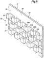
Figure 5 is an enlarged perspective view of a first surface of the first plate; and -
Figure 6 is a sectional view of the thermoelectric power generation device. - A preferred embodiment of the present invention is described in the following with reference to the appended drawings. As shown in
Figure 1 , the thermoelectric power generation device 1 has a plurality ofplates thermoelectric modules 5 each interposed betweenpredetermined plates plates thermoelectric modules 5 are grouped into a plurality of identicalminimum units 7 each consisting of thethermoelectric modules 5, and thefirst plate 2 and thesecond plate 3 interposing thethermoelectric modules 5 therebetween. - The
first plate 2 and thesecond plate 3 belonging to eachunit 7 are each made of a metallic plate member having a substantially rectangular identical shape. In the illustrated embodiment, thefirst plates 2 and thesecond plates 3 are provided with a shape of a rectangle elongated in the vertical direction. Thefirst plates 2 and thesecond plates 3 are each provided with afront surface rear surface first plates 2 and thesecond plates 3 are stacked in the fore and aft direction so that therear surface 2B of eachfirst plate 2 faces thefront surface 3A of the corresponding second plate 3 (belonging to the adjoining unit 7). - As shown in
Figures 2 and3 , thefirst plates 2 and thesecond plates 3 are each provided with afirst hole second hole third hole fourth hole first holes second plates second holes third holes fourth holes second plates first holes second holes third holes fourth holes plates - The
rear surface 2B of acentral part 2G of eachfirst plate 2 and thefront surface 3A of acentral part 3G of thesecond plate 3 are each formed as a smooth flat surface. More specifically, thecentral parts respective plates side edge parts plates Upper end parts first holes second holes plates lower end parts third holes fourth holes side edge parts central parts beads 11 have a function of increasing the bending stiffness of thefirst plates 2 and thesecond plates 3. In addition, as will be described later, flow separation and vibrations of the fluid flowing along the front surfaces of thefirst plates 2 and the rear surfaces of thesecond plates 3 are induced so that turbulence is promoted in the flow. - A plurality of
thermoelectric modules 5 are arranged in thecentral part 3G of the front surface of eachsecond plate 3. Eachthermoelectric module 5 consists of a plurality ofthermoelectric elements Figure 4 , for example, eachthermoelectric module 5 includes a pair ofplates thermoelectric elements plates thermoelectric elements type semiconductors 15A and a plurality of n-type semiconductors 15B. Thethermoelectric elements respective plates plates thermoelectric element 15A positioned on the side of one of theplates 13A is connected to the end portion of the adjacentthermoelectric element 15B on the side of the oneplate 13A via anelectrode 16. Similarly, the end portion of eachthermoelectric element 15A positioned on the side of theother plate 13B is connected to the end portion of the adjacentthermoelectric element 15B on the side of theother plate 13B via anelectrode 16. Aninsulator 17 is interposed between thethermoelectric elements electrode 16 and the opposingplate 13A. Thus, thethermoelectric elements thermoelectric elements thermoelectric elements thermoelectric module 5 are connected in series, and the electrodes forming the two ends of the electric circuit are connected to respective lead wires (SeeFigure 6 ). - The edges of the two
plates thermoelectric module 5 are connected to each other except for the parts from which thelead wires 18 are drawn out. Eachthermoelectric module 5 is formed in a flat rectangular parallelepiped shape having a major plane defined by theplates thermoelectric modules 5 is positioned on thefront surface 3A of thesecond plate 3 in such a manner that the major plane thereof is directed in the fore and aft direction. The front and rear surfaces of thethermoelectric modules 5 are formed as smooth flat surfaces. - As shown in
Figure 6 , ashim plate 20 is interposed between thecentral part 3G of thefront surface 3A of eachsecond plate 3 and the correspondingthermoelectric modules 5. Theshim plate 20 is provided with a prescribed thickness which is selected in dependence on the distance between therear surface 2B of thefirst plate 2 and thefront surface 3A of thesecond plate 3 in such a manner that the front surface of theplates 13A of thethermoelectric modules 5 can contact therear surface 2B of thefirst plate 2 or a member attached to therear surface 2B. Theshim plate 20 is made of metal having a high thermal conductivity such as copper or aluminum, and is provided with a smooth and flat front surface and rear surface. A thermallyconductive grease 21 is interposed between theshim plate 20 and thecentral part 3G of thefront surface 3A of thesecond plate 3 and between theshim plate 20 and the rear surface of thethermoelectric modules 5. The thermallyconductive grease 21 may consist of a per se known thermally conductive grease in which particles of metal or metal oxide having high thermal conductivity such as copper, aluminum, magnesium oxide or the like are dispersed in silicone grease or the like. The thermallyconductive grease 21 fills the gap between thecentral part 3G of thefront surface 3A of thesecond plate 3 and theshim plate 20, and the gap between theshim plate 20 and thethermoelectric modules 5 so that the thermal conductivity between thesecond plate 3 and thethermoelectric modules 5 may be improved. - The
shim plate 20 is held attached to thecentral part 3G of thefront surface 3A of thesecond plate 3, and thethermoelectric modules 5 are held attached to the front surface of theshim plate 20, owing to the viscosity of the thermallyconductive grease 21 in each case. Thelead wires 18 of thethermoelectric modules 5 may be connected in series, in parallel or in other way as required. - As shown in
Figures 3 and6 , thecentral part 2G of therear surface 2B of eachfirst plate 2 retains ametal film 25 with a thermallyconductive grease 21. Themetal film 25 is formed of copper, aluminum or the like. Themetal film 25 may be divided into a plurality of pieces so as to correspond to the front surfaces of the individualthermoelectric modules 5, or may consist of a single piece as to correspond to the front surfaces (plates 13A) of thethermoelectric modules 5. Themetal film 25 is preferably sized so as to come into contact with the whole area of the front surface of each individualthermoelectric module 5, and prevent a contact between the thermallyconductive grease 21 and thethermoelectric modules 5. - As shown in
Figures 1 and2 , afirst gasket 30 is interposed between therear surface 2B of thefirst plate 2 and thefront surface 3A of thesecond plate 3. Thefirst gasket 30 includes a frame portion that surrounds thecentral parts second plates first holes second holes third holes fourth holes rear surface 2B of thefirst plate 2 and thefront surface 3A of thesecond plate 3 which are in contact with thefirst gasket 30 are provided with planar surfaces. Parts of the frame portion surrounding thecentral parts lead wires 18 are passed. The lead out portions may be formed by reducing the thickness of the corresponding parts of thefirst gasket 30. - When the
first plate 2 and thesecond plate 3 are assembled to each other with thefirst gasket 30 interposed therebetween, the space defined between therear surface 2B of thefirst plate 2 and thefront surface 3A of thesecond plate 3 is divided into a space containing thecentral parts first holes second holes third holes fourth holes central parts thermoelectric module 5 is in surface contact with themetal film 25 provided on therear surface 2B of the correspondingfirst plate 2. - As shown in
Figure 2 , aspacer 32 is provided in thecentral part 2G of thefront surface 2A of eachfirst plate 2. When the plurality ofunits 7 are stacked in the fore and aft direction, thespacer 32 abuts against thecentral part 2G of thefront surface 2A of thefirst plate 2 and thecentral part 3G of therear surface 3B of thesecond plate 3 at a plurality of locations so that a distance between thefront surface 2A of the first plate and therear surface 3B of thesecond plate 3 is maintained, and, at the same time, affords a stiffness to thecentral parts first plate 2 and thesecond plate 3 by supporting thecentral parts first plate 2 and thesecond plate 3. - As shown in
Figure 5 , in the illustrated embodiment, thespacer 32 includes a plurality of metal strips 33 (metal plates) extending in the lateral direction and each bent in a wavy manner such that eachmetal strip 33 is provided withprotrusions 33B projecting forward and recesses 33A recessed rearward at a regular interval and in an alternating manner. The metal strips 33 are vertically arranged in a mutually spaced apart relationship in such a manner that theprotrusions 33B of eachmetal strip 33 is offset from theprotrusions 33B of the adjoining metal strips 33 by one half of the width of eachprotrusion 33B. As a result, the passages (spaces) formed by theprotrusions 33B and therecesses 33A are not aligned in the vertical direction (shifted laterally) with the result that the turbulence of the fluid flowing through the passages is further promoted. In another embodiment, the metal strips 33 are offset laterally from the adjoining metal strips 33 by the width of eachprotrusion 33B. The parts of the metal strips 33 corresponding to the bottoms of therecesses 33A are in surface contact with thefront surface 2A of thefirst plate 2, and are welded to thefront surface 2A of thefirst plate 2. The front end surfaces of theprotrusions 33B are located on a common hypothetical plane which is in parallel with thefront surface 2A of thefirst plate 2. Therefore, when theunits 7 are stacked upon one another, the front end surfaces of theprotrusions 33B are in surface contact with thecentral parts 3G of therear surfaces 3B of thesecond plate 3. - As shown in
Figure 1 , asecond gasket 35 or athird gasket 36 is interposed between therear surface 3B of thesecond plate 3 and thefront surface 2A of thefirst plate 2. Thesecond gasket 35 includes a frame portion continuously surrounding thecentral parts second plates first holes third holes holes fourth holes third gasket 36 includes a frame portion continuously surrounding thecentral parts second plates fourth holes third holes holes third holes second gasket 35 and thethird gasket 36 are alternately disposed between therear surface 3B of thesecond plate 3 and thefront surface 2A of thefirst plate 2 when the plurality ofunits 7 are stacked upon one another. In other words, thefirst plate 2, thefirst gasket 30, thesecond plate 3, thesecond gasket 35, thefirst plate 2, thefirst gasket 30, thesecond plate 3, and thethird gasket 36 are stacked upon one another in this order in a repeated pattern. - In the assembled state in which the
second gasket 35 is interposed between thefirst plate 2 and thesecond plate 3, the space between therear surface 3B of thesecond plate 3 and thefront surface 2A of thefirst plate 2 is divided into a space containing thecentral parts first holes third holes 2E and3E, a space containing thesecond holes fourth holes protrusions 33B of thespacer 32 are in surface contact with thecentral parts 3G of therear surface 3B of thesecond plate 3. - A
front end plate 41 is positioned on the front side of theunits 7 stacked upon one another in the fore and aft direction, and arear end plate 42 is positioned on the rear side of theunits 7. Thefront end plate 41 has a configuration similar to that of thefirst plate 2. Specifically, thefront end plate 41 is provided with a first to afourth hole 41C to 41F corresponding to the first tofourth holes 2C to 2F, and aspacer 32 is positioned on the front surface of thefront end plate 41. Therear end plate 42 has a configuration similar to that of thefirst plate 2 except for that the first tofourth holes 2C to 2F are absent in this case, and aspacer 32 is positioned on the front surface of therear end plate 42. A frontouter plate 44 is positioned on the front side of thefront end plate 41, and a rearouter plate 45 is positioned on the rear side of therear end plate 42. - The front
outer plate 44 is provided with a high temperaturefluid inlet hole 44C opposing thefirst hole 41C of thefront end plate 41, a low temperaturefluid outlet hole 44D opposing thesecond hole 41D, a high temperaturefluid outlet hole 44E opposing thethird hole 41E, and a low temperaturefluid inlet hole 44F opposing thefourth hole 41F. The high temperaturefluid inlet hole 44C, the low temperaturefluid outlet hole 44D, the high temperaturefluid outlet hole 44E, and the low temperaturefluid inlet hole 44F penetrate the frontouter plate 44 in the thickness direction. The high temperaturefluid inlet hole 44C is connected to a high temperature fluid source, the high temperaturefluid outlet hole 44E is connected to a high temperature fluid discharge drain, the low temperaturefluid inlet hole 44F is connected to a low temperature fluid source, and the low temperaturefluid outlet hole 44D is connected to a low temperature fluid discharge drain. - A
first gasket 30 is interposed between the rear surface of the frontouter plate 44 and the front surface of thefront end plate 41. Asecond gasket 35 is interposed between the rear surface of thefront end plate 41 and thefront surface 2A of thefirst plate 2 of theunit 7 arranged at the frontmost end. Athird gasket 36 is interposed between therear surface 3B of thesecond plate 3 of theunit 7 arranged at the rearmost end and the front surface of therear end plate 42. - The front
outer plate 44 and the rearouter plate 45 are joined by a plurality of tie rods (not shown in the drawings) extending in the fore and aft direction. Thefront end plate 41, the plurality ofunits 7, therear end plate 42, and thevarious gaskets outer plate 44 and the rearouter plate 45 in the fore and aft direction. - The rear surface of the front
outer plate 44, thefirst gasket 30, and the front surface of thefront end plate 41 jointly define a passage connecting the high temperaturefluid inlet hole 44C with thefirst hole 41C, a passage connecting the low temperaturefluid outlet hole 44D with thesecond hole 41D, a passage connecting the high temperaturefluid outlet hole 44E with thethird hole 41E, and a passage connecting the low temperaturefluid inlet hole 44F with thefourth hole 41F. - The
rear surface 2B of thefirst plate 2, thefirst gasket 30, and thefront surface 3A of thesecond plate 3 jointly define a passage connecting thefirst holes second plates second holes third holes fourth holes central parts thermoelectric modules 5 are disposed from these passages. - The
rear surface 3B of the second plate 3 (or the rear surface of the front end plate 41), thesecond gasket 35, and thefront surface 3A of thefirst plate 2 jointly define a hightemperature fluid passage 51 that connects thefirst holes central parts third holes respective plates 2 and 3 (41) to one another. The hightemperature fluid passage 51 extends obliquely in a diagonal direction from thefirst holes third holes Figures 1 and6 ) or from above to below. The hightemperature fluid passage 51 is provided with a larger lateral width in thecentral parts upper end parts lower end parts - The
rear surface 3B of thesecond plate 3, thesecond gasket 36, and thefront surface 3A of the first plate 2 (or the front surface of the rear end plate 42) jointly define a lowtemperature fluid passage 52 that connects thesecond holes central parts fourth holes respective plates 2 and 3 (41) to one another. The lowtemperature fluid passage 52 extends obliquely in a diagonal direction from thefourth holes second holes Figures 1 and6 ) or from below to above. The lowtemperature fluid passage 52 is provided with a larger lateral width in thecentral parts upper end parts lower end parts - Owing to such arrangements, the high temperature fluid supplied to the high temperature
fluid inlet hole 44C sequentially passes through thefirst holes temperature fluid passages 51, thethird holes fluid outlet hole 44E. Meanwhile, the low temperature fluid supplied to the low temperaturefluid inlet hole 44F sequentially passes through thefourth holes temperature fluid passages 52, thesecond holes fluid outlet hole 44D. As a result, the high temperature fluid and the low temperature fluid flow along thefront surface 2A of thefirst plate 2 and therear surface 3B of thesecond plate 3, respectively, as counterflows so that a temperature difference is created between thefront surface 2A and therear surface 3B of the twoplates thermoelectric modules 5 therebetween. - In the thermoelectric power generation device 1 of the embodiment configured as described above, since the
central parts first plate 2 and thesecond plate 3 facing thethermoelectric modules 5 are formed as planar surfaces, the contact area between thefirst plate 2 and thethermoelectric modules 5 intervened by themetal film 25, and the contact area between thesecond plate 3 and thethermoelectric modules 5 intervened by theshim plate 20 are maximized so that heat exchange between thethermoelectric modules 5, and thefirst plate 2 and thesecond plate 3 can be promoted. As a result, the temperature difference created between the front surface and the rear surface of thethermoelectric modules 5 increases, and the power generation efficiency of thethermoelectric modules 5 is improved. Since the first andsecond plates spacers 32 arranged between the first andsecond plates second plates second plates spacers 32, it is possible to reduce the thickness of the first andsecond plates thermoelectric modules 5, and the high temperature fluid and the low temperature fluid. - Since each
spacer 32 is attached to thefirst plate 2, the stiffness of thefirst plate 2 is further improved. Further, since eachspacer 32 is attached to thefirst plate 2, the thermoelectric power generation device 1 can be easily assembled. - Each
spacer 32 crosses the hightemperature fluid passage 51 and the lowtemperature fluid passage 52 so as to distribute the hightemperature fluid passage 51 and the lowtemperature fluid passage 52 into a plurality of passages at discrete locations. Therefore, the turbulence of the flows of the high temperature fluid and the low temperature fluid can be enhanced. This also promotes homogenization of the high temperature fluid and the low temperature fluid flowing in the hightemperature fluid passage 51 and the lowtemperature fluid passage 52. In addition, flow separation of the high temperature fluid and the low temperature fluid from thefront surface 2A of thefirst plate 2 and therear surface 3B of thesecond plate 3 is promoted by thespacer 32, and this also promotes the turbulent flow. As a result, heat exchange between the high temperature fluid and the low temperature fluid and the first andsecond plates - If both of the surfaces of the
thermoelectric modules 5 are in contact with thefirst plate 2 and thesecond plate 3 with an adhesive such as thermallyconductive grease 21 or the like, when thefirst plate 2 and thesecond plate 3 are removed, thethermoelectric modules 5 could be damaged. In the illustrated embodiment, only the rear surface of thethermoelectric modules 5 is brought into close contact with theshim plate 20 provided on thesecond plate 3 by the thermallyconductive grease 21 while the front surface of thethermoelectric modules 5 is simply brought into contact with therear surface 2B of thefirst plate 2, thethermoelectric modules 5 are protected from excessive loading, and prevented from breaking when therear surface 2B of thefirst plate 2 and thefront surface 3A of thesecond plate 3 disassembled at the time of maintenance or the like, so that breakage of thethermoelectric modules 5 is avoided. - The
metal film 25 is adhered to therear surface 2B of thefirst plate 2 by the thermallyconductive grease 21. Therefore, themetal film 25 can be deformed together with the thermallyconductive grease 21 so as to conform to the front surface of thethermoelectric modules 5 so that the contact betweenmetal film 25 and thethermoelectric modules 5 is improved. - The present invention has been described in terms of a specific embodiment, but is not limited by this embodiment, and can be modified without departing from the spirt of the present invention. For example, in the above embodiment, the
spacer 32 is attached to thefront surface 2A of thefirst plate 2, but thespacer 32 may also be attached to therear surface 3B of thesecond plate 3, instead of thefront surface 2A of thefirst plate 2. Furthermore, thespacer 32 may also be attached to both thefront surface 2A of thefirst plate 2 and therear surface 3B of thesecond plate 3. It can also be arranged such that thefirst spacer 32 is attached to thefront surface 2A of thefirst plate 2 while thesecond spacer 32 is attached to therear surface 3B of thesecond plate 3, and thefirst spacer 32 and thesecond spacer 32 are in contact with each other. Thespacer 32 may not be attached to either thefirst plate 2 or thesecond plate 3, and may be interposed between thefront surface 2A of thefirst plate 2 and therear surface 3B of thesecond plate 3. - Further, in the illustrated embodiment, the
spacer 32 is formed of a plurality of metal strips 33 (metal plates) independent from each other. However, the metal strips 33 may be connected to each other by a connecting member or the like extending vertically. Further, a single plate having irregularities formed by embossing or the like may be connected to thefirst plate 2. - In an alternate embodiment, the
spacer 32 is interposed between thefirst plate 2 and thesecond plate 3 without being welded or bonded to either thefirst plate 2 or thesecond plate 3. Thespacer 32 partitions the space between thefirst plate 2 and thesecond plate 3 into a plurality of continuous passages (spaces). Thespacer 32 may be formed from a single member or a plurality of members. Each member constituting thespacer 32 may consist of a plate-like member which is provided with a plurality of protrusions and depressions formed by embossing or the like, or a plurality of through holes. Thespacer 32 may be positioned relative to thefirst plate 2 and thesecond plate 3 by being engaged by protrusions formed on thefirst plate 2 and/or thesecond plate 3. Furthermore, thespacer 32 may be provided with engagement portions configured to be engaged by the edges of at least some of thefirst holes second holes third holes fourth holes first plate 2 and thesecond plate 3 so that thespacer 32 may be positioned relative to thefirst plate 2 and thesecond plate 3 by the engagement portions thereof engaging at least some of the first tofourth holes 2C-2F, 3C-3F, of thefirst plate 2 of thesecond plate 3. - Furthermore, the
spacer 32 may be integrally formed with thesecond gasket 35 or thethird gasket 36 interposed between thefirst plate 2 and thesecond plate 3. In such a case, thespacer 32 may be formed of the same material as thegaskets gaskets - The
shim plate 20 may be omitted depending on the thickness of thethermoelectric modules 5 and the distance between therear surface 2B of thefirst plate 2 and thefront surface 3A of thesecond plate 3. In such a case, the rear surface of thethermoelectric modules 5 may be retained on thefront surface 3A of thesecond plate 3 by using the thermallyconductive grease 21. - In the above embodiment, as shown in
Figure 6 , a plurality ofthermoelectric modules 5 are connected by thelead wires 18. Alternatively, a plurality ofthermoelectric modules 5 may be disposed on a printed board on which a circuit is formed, andthermoelectric modules 5 may be connected to thelead wires 18 via the printed circuit. The printed circuit board may be directly held on theshim plate 20 or thesecond plate 3 by using the thermallyconductive grease 21. It is preferable that the printed circuit board consists of a flexible printed circuit board having a small thickness. - In the above embodiment, the flow directions of the high
temperature fluid passage 51 and the lowtemperature fluid passage 52 are inclined with respect to the vertical direction. However, in an alternate embodiment, the flow directions of the hightemperature fluid passage 51 and the lowtemperature fluid passage 52 extend vertically and in parallel to each other. In such a case, the high temperaturefluid inlet hole 44C is disposed at the upper left corner part of the frontouter plate 44 and connected to thesecond holes fluid outlet hole 44E is disposed at the lower left corner part of the frontouter plate 44, the low temperaturefluid inlet hole 44F is disposed at the lower right corner part of the frontouter plate 44 and connected to thefourth holes fluid outlet hole 44D is disposed at the upper right corner part of the frontouter plate 44 and connected to thefirst holes second gasket 35 includes a frame portion continuously surrounding thecentral parts first holes fourth holes second plates second holes third holes third gasket 36 may include a frame portion continuously surrounding thecentral parts second plates second holes third holes holes fourth holes - The configuration of the
thermoelectric modules 5 shown inFigure 4 is an example, and various other per se known configurations can also be applied. - In the above embodiment, the
first plate 2, thesecond plate 3, and the like are formed with a substantially rectangular outer shape, but the shape may be freely selected such as a circle.GLOSSARY OF TERMS 1 thermoelectric power generation device 2 first plate 2A front surface 2B rear surface 2G central part 3 second plate 3A front surface 3B rear surface 3G central part 3H upper end part 3J lower end part 5 thermoelectric module 7 unit 11 beads 15A, 15B thermoelectric element 20 shim plate 21 thermally conductive grease 25 metal film 30 first gasket 32 spacer 33 metal plate 33A recess 33B protrusion 35 second gasket 36 third gasket 51 high temperature fluid passage 52 low temperature fluid passage
Claims (9)
- A thermoelectric power generation device, comprising
a plurality of units that are stacked upon one another, each unit including a thermoelectric module containing at least one thermoelectric element, and a first plate and a second plate interposing the thermoelectric module therebetween,
wherein a spacer is interposed between a surface of one of the first plates facing away from the corresponding thermoelectric module and a surface of the opposing second plate facing away from the corresponding thermoelectric module, the spacer contacting the first plate and the second plate and defining a fluid passage jointly with the first plate and the second plate, and
wherein the fluid passages defined between the adjacent units are configured to receive supply of high temperature fluid and low temperature fluid in an alternating manner in a stacking direction of the units. - The thermoelectric power generation device according to claim 1, wherein each spacer is interposed between the first plate and the second plate.
- The thermoelectric power generation device according to claim 1 or 2, wherein each spacer is attached to one of the corresponding first plate and second plate.
- The thermoelectric power generation device according to claim 2 or 3, wherein each spacer is a metal plate bent so as to form a plurality of protrusions and depressions.
- The thermoelectric power generation device according to any one of claims 1 to 4, wherein each thermoelectric module is bonded to one of the first plate and the second plate, and is in contact with the other of the first plate and the second plate.
- The thermoelectric power generation device according to any one of claims 1 to 4, wherein the thermoelectric module is bonded to one of the first plate and the second plate and contacts a metal film attached to the other of the first plate and the second plate.
- The thermoelectric power generation device according to claim 6, wherein the metal film is attached to the other of the first plate and the second plate via a thermally conductive grease.
- The thermoelectric power generation device according to any one of claims 1 to 7, wherein parts of the first plate and the second plate which face the thermoelectric module are formed as planar surfaces.
- A thermoelectric power generation method using the thermoelectric power generation device according to any one of claims 1 to 8, comprising the step of supplying the high temperature fluid of a comparatively high temperature and the low temperature fluid of a comparatively low temperature to the fluid passages defined in the spacers in an alternating manner in the stacking direction of the units.
Applications Claiming Priority (2)
| Application Number | Priority Date | Filing Date | Title |
|---|---|---|---|
| JP2015195986 | 2015-10-01 | ||
| PCT/JP2016/004456 WO2017056514A1 (en) | 2015-10-01 | 2016-10-03 | Thermoelectric power generation device and thermoelectric power generation method |
Publications (2)
| Publication Number | Publication Date |
|---|---|
| EP3358634A1 true EP3358634A1 (en) | 2018-08-08 |
| EP3358634A4 EP3358634A4 (en) | 2019-05-08 |
Family
ID=58422949
Family Applications (1)
| Application Number | Title | Priority Date | Filing Date |
|---|---|---|---|
| EP16850692.1A Withdrawn EP3358634A4 (en) | 2015-10-01 | 2016-10-03 | DEVICE FOR PRODUCING THERMOELECTRIC ENERGY AND METHOD FOR PRODUCING THERMOELECTRIC ENERGY |
Country Status (7)
| Country | Link |
|---|---|
| US (1) | US20180287036A1 (en) |
| EP (1) | EP3358634A4 (en) |
| JP (1) | JP6646859B2 (en) |
| KR (1) | KR102098362B1 (en) |
| CN (1) | CN108140712B (en) |
| PH (1) | PH12018500705A1 (en) |
| WO (1) | WO2017056514A1 (en) |
Cited By (1)
| Publication number | Priority date | Publication date | Assignee | Title |
|---|---|---|---|---|
| GB2622080A (en) * | 2022-09-02 | 2024-03-06 | Philip Duffy James | Plate heat exchanger |
Families Citing this family (6)
| Publication number | Priority date | Publication date | Assignee | Title |
|---|---|---|---|---|
| JP6851945B2 (en) * | 2017-09-19 | 2021-03-31 | 株式会社東芝 | Thermoelectric generation system |
| KR102794636B1 (en) * | 2020-01-13 | 2025-04-14 | 엘지이노텍 주식회사 | Heat conversion device |
| US20260020497A1 (en) * | 2022-07-13 | 2026-01-15 | National Thermovoltaics Inc. | Thermoelectric generator apparatuses and systems |
| KR102648693B1 (en) * | 2022-12-16 | 2024-03-19 | 최병규 | Appratus for testing semiconductor device |
| WO2025101005A1 (en) * | 2023-11-10 | 2025-05-15 | 엘지이노텍 주식회사 | Heat exchange device comprising thermoelectric element |
| WO2025101006A1 (en) * | 2023-11-10 | 2025-05-15 | 엘지이노텍 주식회사 | Heat exchange device including thermoelectric element |
Family Cites Families (15)
| Publication number | Priority date | Publication date | Assignee | Title |
|---|---|---|---|---|
| US5584183A (en) * | 1994-02-18 | 1996-12-17 | Solid State Cooling Systems | Thermoelectric heat exchanger |
| US7273981B2 (en) * | 2001-02-09 | 2007-09-25 | Bsst, Llc. | Thermoelectric power generation systems |
| US20040089336A1 (en) * | 2001-06-11 | 2004-05-13 | Hunt Robert D. | Thermoelectric vaporizers, generators and heaters/coolers |
| JP4829552B2 (en) * | 2004-07-06 | 2011-12-07 | 財団法人電力中央研究所 | Thermoelectric conversion module |
| US20060005873A1 (en) * | 2004-07-06 | 2006-01-12 | Mitsuru Kambe | Thermoelectric conversion module |
| US20060157102A1 (en) * | 2005-01-12 | 2006-07-20 | Showa Denko K.K. | Waste heat recovery system and thermoelectric conversion system |
| JP2009087955A (en) * | 2005-01-12 | 2009-04-23 | Showa Denko Kk | Waste heat recovery system with thermoelectric conversion system |
| WO2007026432A1 (en) * | 2005-08-31 | 2007-03-08 | Hitachi, Ltd. | Egr gas power generator |
| US20070095379A1 (en) * | 2005-10-31 | 2007-05-03 | Taher Mahmoud A | Thermoelectric generator |
| US7765811B2 (en) * | 2007-06-29 | 2010-08-03 | Laird Technologies, Inc. | Flexible assemblies with integrated thermoelectric modules suitable for use in extracting power from or dissipating heat from fluid conduits |
| JP2009081970A (en) | 2007-09-27 | 2009-04-16 | Ihi Marine United Inc | Thermoelectric power generator and power generation system using the thermoelectric power generator |
| JP5889584B2 (en) * | 2010-09-10 | 2016-03-22 | 株式会社東芝 | Temperature difference power generator and thermoelectric conversion element frame |
| US20130213449A1 (en) * | 2012-02-20 | 2013-08-22 | Marlow Industries, Inc. | Thermoelectric plate and frame exchanger |
| KR20140083335A (en) * | 2012-12-26 | 2014-07-04 | 현대자동차주식회사 | Heat exchanger with thermoelectric element |
| US20150243870A1 (en) * | 2013-04-23 | 2015-08-27 | Hi-Z Technology, Inc. | Compact high power density thermoelectric generator |
-
2016
- 2016-10-03 US US15/764,440 patent/US20180287036A1/en not_active Abandoned
- 2016-10-03 JP JP2017542760A patent/JP6646859B2/en not_active Expired - Fee Related
- 2016-10-03 EP EP16850692.1A patent/EP3358634A4/en not_active Withdrawn
- 2016-10-03 CN CN201680057633.3A patent/CN108140712B/en not_active Expired - Fee Related
- 2016-10-03 KR KR1020187012178A patent/KR102098362B1/en not_active Expired - Fee Related
- 2016-10-03 WO PCT/JP2016/004456 patent/WO2017056514A1/en not_active Ceased
-
2018
- 2018-03-28 PH PH12018500705A patent/PH12018500705A1/en unknown
Cited By (1)
| Publication number | Priority date | Publication date | Assignee | Title |
|---|---|---|---|---|
| GB2622080A (en) * | 2022-09-02 | 2024-03-06 | Philip Duffy James | Plate heat exchanger |
Also Published As
| Publication number | Publication date |
|---|---|
| US20180287036A1 (en) | 2018-10-04 |
| JP6646859B2 (en) | 2020-02-14 |
| KR102098362B1 (en) | 2020-04-07 |
| WO2017056514A1 (en) | 2017-04-06 |
| JPWO2017056514A1 (en) | 2018-07-05 |
| EP3358634A4 (en) | 2019-05-08 |
| CN108140712B (en) | 2021-08-27 |
| CN108140712A (en) | 2018-06-08 |
| KR20180063207A (en) | 2018-06-11 |
| PH12018500705A1 (en) | 2018-10-15 |
Similar Documents
| Publication | Publication Date | Title |
|---|---|---|
| US20180287036A1 (en) | Thermoelectric power generation device and thermoelectric power generation method | |
| US10274259B2 (en) | Multi-sided heat exchangers with compliant heat transfer surfaces | |
| US10215504B2 (en) | Flexible cold plate with enhanced flexibility | |
| CN204375726U (en) | Liquid-cooled-type cooling device and liquid-cooled-type cooling device radiator | |
| US6815814B2 (en) | Thermoelectric module | |
| KR102351954B1 (en) | heat exchanger for cooling electric element | |
| US8492019B2 (en) | Extruded thermal fin for temperature control of battery cells | |
| US7044198B2 (en) | Electronic apparatus | |
| US20220102812A1 (en) | Battery pack | |
| EP3327855B1 (en) | Battery system and method of assembling the battery system | |
| CN106787620B (en) | Power converter | |
| US20110240631A1 (en) | Electrical heating unit, particularly for cars | |
| US20220142009A1 (en) | Water-cooler heat dissipation device and electrical device | |
| JP6369403B2 (en) | Semiconductor device | |
| US6278611B1 (en) | Plenumless air cooled avionics rack | |
| US10629794B2 (en) | Thermoelectric power generation device and method for manufacturing same | |
| JP5163160B2 (en) | Semiconductor cooling structure | |
| JP6972990B2 (en) | Heat pump device | |
| CN120686956A (en) | Water cooling plate assembly | |
| CN107851642A (en) | Crimp type semiconductor devices stacks | |
| EP2216807A2 (en) | Heat-dissipation apparatus | |
| CN110120389B (en) | Semiconductor device | |
| JP2009152172A (en) | Electric heater | |
| KR200306641Y1 (en) | Structure of a heat dissipation device for computers | |
| CN117596730A (en) | Electric heating device |
Legal Events
| Date | Code | Title | Description |
|---|---|---|---|
| STAA | Information on the status of an ep patent application or granted ep patent |
Free format text: STATUS: THE INTERNATIONAL PUBLICATION HAS BEEN MADE |
|
| PUAI | Public reference made under article 153(3) epc to a published international application that has entered the european phase |
Free format text: ORIGINAL CODE: 0009012 |
|
| STAA | Information on the status of an ep patent application or granted ep patent |
Free format text: STATUS: REQUEST FOR EXAMINATION WAS MADE |
|
| 17P | Request for examination filed |
Effective date: 20180430 |
|
| AK | Designated contracting states |
Kind code of ref document: A1 Designated state(s): AL AT BE BG CH CY CZ DE DK EE ES FI FR GB GR HR HU IE IS IT LI LT LU LV MC MK MT NL NO PL PT RO RS SE SI SK SM TR |
|
| AX | Request for extension of the european patent |
Extension state: BA ME |
|
| DAV | Request for validation of the european patent (deleted) | ||
| DAX | Request for extension of the european patent (deleted) | ||
| A4 | Supplementary search report drawn up and despatched |
Effective date: 20190410 |
|
| RIC1 | Information provided on ipc code assigned before grant |
Ipc: H01L 35/30 20060101AFI20190404BHEP Ipc: H01L 35/32 20060101ALI20190404BHEP |
|
| GRAP | Despatch of communication of intention to grant a patent |
Free format text: ORIGINAL CODE: EPIDOSNIGR1 |
|
| STAA | Information on the status of an ep patent application or granted ep patent |
Free format text: STATUS: GRANT OF PATENT IS INTENDED |
|
| INTG | Intention to grant announced |
Effective date: 20200312 |
|
| STAA | Information on the status of an ep patent application or granted ep patent |
Free format text: STATUS: THE APPLICATION IS DEEMED TO BE WITHDRAWN |
|
| 18D | Application deemed to be withdrawn |
Effective date: 20200723 |