EP3358564A1 - Wind instrument - Google Patents
Wind instrument Download PDFInfo
- Publication number
- EP3358564A1 EP3358564A1 EP16851262.2A EP16851262A EP3358564A1 EP 3358564 A1 EP3358564 A1 EP 3358564A1 EP 16851262 A EP16851262 A EP 16851262A EP 3358564 A1 EP3358564 A1 EP 3358564A1
- Authority
- EP
- European Patent Office
- Prior art keywords
- tube
- tone hole
- wind instrument
- tube body
- finger
- Prior art date
- Legal status (The legal status is an assumption and is not a legal conclusion. Google has not performed a legal analysis and makes no representation as to the accuracy of the status listed.)
- Granted
Links
Images



Classifications
-
- G—PHYSICS
- G10—MUSICAL INSTRUMENTS; ACOUSTICS
- G10D—STRINGED MUSICAL INSTRUMENTS; WIND MUSICAL INSTRUMENTS; ACCORDIONS OR CONCERTINAS; PERCUSSION MUSICAL INSTRUMENTS; AEOLIAN HARPS; SINGING-FLAME MUSICAL INSTRUMENTS; MUSICAL INSTRUMENTS NOT OTHERWISE PROVIDED FOR
- G10D9/00—Details of, or accessories for, wind musical instruments
- G10D9/10—Resonating bodies, e.g. tubes
-
- G—PHYSICS
- G10—MUSICAL INSTRUMENTS; ACOUSTICS
- G10D—STRINGED MUSICAL INSTRUMENTS; WIND MUSICAL INSTRUMENTS; ACCORDIONS OR CONCERTINAS; PERCUSSION MUSICAL INSTRUMENTS; AEOLIAN HARPS; SINGING-FLAME MUSICAL INSTRUMENTS; MUSICAL INSTRUMENTS NOT OTHERWISE PROVIDED FOR
- G10D7/00—General design of wind musical instruments
-
- G—PHYSICS
- G10—MUSICAL INSTRUMENTS; ACOUSTICS
- G10D—STRINGED MUSICAL INSTRUMENTS; WIND MUSICAL INSTRUMENTS; ACCORDIONS OR CONCERTINAS; PERCUSSION MUSICAL INSTRUMENTS; AEOLIAN HARPS; SINGING-FLAME MUSICAL INSTRUMENTS; MUSICAL INSTRUMENTS NOT OTHERWISE PROVIDED FOR
- G10D7/00—General design of wind musical instruments
- G10D7/02—General design of wind musical instruments of the type wherein an air current is directed against a ramp edge
-
- G—PHYSICS
- G10—MUSICAL INSTRUMENTS; ACOUSTICS
- G10D—STRINGED MUSICAL INSTRUMENTS; WIND MUSICAL INSTRUMENTS; ACCORDIONS OR CONCERTINAS; PERCUSSION MUSICAL INSTRUMENTS; AEOLIAN HARPS; SINGING-FLAME MUSICAL INSTRUMENTS; MUSICAL INSTRUMENTS NOT OTHERWISE PROVIDED FOR
- G10D7/00—General design of wind musical instruments
- G10D7/06—Beating-reed wind instruments, e.g. single or double reed wind instruments
-
- G—PHYSICS
- G10—MUSICAL INSTRUMENTS; ACOUSTICS
- G10D—STRINGED MUSICAL INSTRUMENTS; WIND MUSICAL INSTRUMENTS; ACCORDIONS OR CONCERTINAS; PERCUSSION MUSICAL INSTRUMENTS; AEOLIAN HARPS; SINGING-FLAME MUSICAL INSTRUMENTS; MUSICAL INSTRUMENTS NOT OTHERWISE PROVIDED FOR
- G10D7/00—General design of wind musical instruments
- G10D7/06—Beating-reed wind instruments, e.g. single or double reed wind instruments
- G10D7/08—Saxophones
Definitions
- the present invention relates to a wind instrument.
- Non-patent Document 1 There is a type of wind instrument, such as a recorder shown for example in Non-patent Document 1, in which the tone holes are directly opened and closed mainly by the fingers of the performer.
- This type of wind instrument has the advantage of being easy to manufacture and inexpensive compared to wind instruments, such as saxophones, in which many tone holes are opened and closed by keys.
- adjustments are made to the pitch and sound production (for example, the volume, sound quality and the like), and adjustments are made to the arrangement of the plurality of tone holes with respect to the tube body in consideration of operability of the wind instrument. It is possible to adjust pitch by changing the positions of the tone holes in the axial direction of the tube body, the diameter size of the tone holes, and the length dimension of the tone holes (height dimension). It is also possible to adjust sound production by changing the diameter size of the tone holes.
- the present invention was achieved in view of the above circumstances, and has as its object to provide a wind instrument that can easily ensure both acoustic performance and operability.
- the present invention provides a wind instrument that is provided with a tube body and a plurality of tone hole tubes each having an outer open end formed at the outer periphery of the tube body and an inner open end formed through the outer opening end and opening to the inside of the tube body, in which at least one of the tube body and the tone hole tubes is curved such that the outer open ends of the plurality of tone hole tubes are in positions corresponding to fingers blocking the outer open ends.
- the present invention provides a wind instrument that is provided with a tube body and a plurality of tone hole tubes each having an inner open end formed extending from the outer periphery of the tube body and opening to the inside of the tube body and an outer open end opening to the outside of the tube body, in which the tone hole tube has an inclined tube portion in which the axial line of the tone hole tube is inclined with respect to the radial direction of the tube body such that the outer open ends of the plurality of tone hole tubes are in positions corresponding to fingers blocking the outer open ends.
- FIGS. 1 to 3 one embodiment of the present invention will be described referring to FIGS. 1 to 3 .
- the wind instrument 1 of the present embodiment is provided with a tube body 2, a tone hole tube 3, a mouth piece 4 (blow hole), a bell 5, and a finger pressing plate 6.
- the mouthpiece 4 and the bell 5 are disposed at both ends of the tube body 2 in the lengthwise direction (X-axis direction).
- the mouthpiece 4, which may for example be integrally formed with the tube body 2, in this embodiment is detachably mounted on the tube body 2.
- the mouthpiece 4, which may be a single reed provided with one sheet-like reed 4A as in the illustrated example, may also for example be an air reed, a lip reed, or a double reed.
- the lengthwise direction of the tube body 2 and the like corresponds to the direction, viewed from a performer playing the wind instrument 1, from the mouthpiece 4 to the bell 5.
- the lengthwise direction of the tube body 2 is called the X-axis direction
- the horizontal direction viewed from the performer is called the Y-axis direction of the tube body 2 and the like
- the vertical direction viewed from the performer is called the Z-axis direction of the tube body 2 and the like, as shown in FIGS. 1 to 3 .
- the tube body 2 may be formed by any one material of for example a wood material, a metal material, and a resin material, and may be formed by for example a material that suitably combines these materials.
- the tube body 2 of the present embodiment is provided with a main tube 11, in which at both ends in the lengthwise direction the mouthpiece 4 and the bell 5 are arranged, and an auxiliary tube 12 that is connected to the main tube 11 so as to branch off from the main tube 11.
- the main tube 11 and the auxiliary tube 12 are formed in a cylindrical shape with the inner diameter dimension of each being fixed.
- the auxiliary tube 12 is connected to a first end portion 13 on the mouthpiece 4 side of the main tube 11.
- the auxiliary tube 12 is disposed at a region on the upper side (the upper side in the Z-axis direction) of the main tube 11, and extends in the X-axis direction and Z-axis direction with respect to the main tube 11. That is, the auxiliary tube 12 does not extend in the Y-axis direction with respect to the main tube 11.
- the auxiliary tube 12 extends so as to follow the tube axis A1 that passes through the center of the main tube 11 (refer to FIG. 3A ), but is not limited thereto.
- the wind instrument 1 of the present embodiment has the same acoustic characteristics as the case of the tube body 2 being conical.
- the tone hole tube 3 constitutes the tone hole of the wind instrument 1 of the present embodiment.
- the tone hole tube 3 has an inner open end 21 that opens to the inside (inner periphery) of the main tube 11, and an outer open end 22 that opens to the outside of the main tube 11.
- the tone hole tube 3 is formed in a cylindrical shape with the inner diameter being fixed.
- a plurality of the tone hole tubes 3 are arrayed spaced apart in the X-axis direction of the main tube 11.
- the position of the inner open end 21 of each tone hole tube 3 along the tube axis A1 of the main tube 11 is set in consideration of the pitch of the wind instrument 1.
- the inner diameter and axial length of each tone hole tube 3 are individually set in consideration of the pitch and sound production (for example, volume, sound quality and the like) of the wind instrument 1. That is, the inner diameter and axial length of the tone hole tubes 3 mutually differ for the plurality of tone hole tubes 3.
- the inner diameter of some of the tone hole tubes 3 (3A to 3E) is set to a size that allows the outer open ends 22 of the tone hole tubes 3 to be blocked by the fingers of the performer.
- the plurality of tone hole tubes 3 are arranged in a row in the X-axis direction of the main tube 11. More specifically, the inner open ends 21 and outer open ends 22 of the plurality of tone hole tubes 3 are disposed at the same position mutually in the Y-axis direction of the main tube 11. Also, the lateral direction (Y-axis direction) of the main tube 11 is not included in the direction in which the plurality of tone hole tubes 3 extend from the main tube 1. In the present embodiment, the plurality of tone hole tubes 3 are all disposed on the upper side (in the Z-axis direction) of the main tube 11.
- the plurality of tone hole tubes 3 each have a portion that extends in the upward direction (Z-axis positive direction) of the main tube 11 with respect to the main tube 11. That is, the tone hole tubes 3A to 3C, 3E, 3F, 3H, and 31 wholly extend straight in the upward direction of the main tube 11.
- the remaining tone hole tubes 3D, 3G, although the tube axis curves as described below, has a part that extends in the upward direction of the main tube 11.
- tone hole tubes 3 constitute tone holes for pitch operation (pitch tone holes) in which, by being opened and closed, the pitch of the wind instrument 1 changes.
- the number of the aforementioned tone hole tubes 3 is nine, and it would be difficult to directly open and close all the tone hole tubes 3 with the performer's fingers. For that reason, the wind instrument 1 of the present embodiment is provided with a key mechanism 8 (key system).
- the first to fifth tone hole tubes 3A to 3E of the nine tone hole tubes 3, counting from the first end portion 13 side of the main tube 11, are directly opened by the fingers of the performer.
- the first to third tone hole tubes 3A, 3B, 3C respectively correspond to the index finger, middle finger, and ring finger of the performer's left hand, while the fourth and fifth tone hole tubes 3D and 3E respectively correspond to the index finger and middle finger of the right hand.
- the sixth to ninth tone hole tubes 3F to 31 are opened and closed by utilizing the key mechanism 8 (key system).
- the key mechanism 8 is operated by the ring finger and little finger of the performer's right hand.
- a thumbhole 14 that is opened and closed by the thumb of the left hand of the performer is also formed in the main tube 11.
- the thumbhole 14 is formed in the main tube 11 at a position more to the first end portion 13 side than the tone hole tube 3A in the X-axis direction of the main tube 11.
- the thumbhole 14 of the present embodiment opens to the downward direction of the main tube 11 (negative direction side on the Z axis).
- the thumbhole 14 changes the pitch of the wind instrument 1 by being opened and closed by a finger of the performer (left hand thumb) similarly to the tone hole tubes 3A to 3E described above.
- the main tube 11 and the tone hole tubes 3D and 3G are curved such that the plurality of outer open ends 22 are provided at positions corresponding to the fingers, and the inner open ends 21 are connected with the tube body 1 at a position that causes the tube body 1 to produce a predetermined pitch.
- this point is described in detail.
- the main tube 11 of the present embodiment is curved a plurality of times in the Z-X plane. That is, the main tube 11 meanders in the vertical direction (Z-axis direction) of the main tube 11. In the present embodiment, the main tube 11 does not meander in the lateral direction (Y-axis direction).
- the main tube 11 extending in the lengthwise direction (X-axis direction) while curving in the vertical direction (Z-axis direction) while curving in the vertical direction (Z-axis direction), the linear length of the main tube 11 in the lengthwise direction (X-axis direction) of the main tube 11 becomes shorter than the length of the main tube 11 along the tube axis A1 of the main tube 11.
- the meandering direction of the main tube 11 may also for example be the lateral direction (Y-axis direction) of the main tube 11.
- the linear distance of the interval between adjacent tone hole tubes 3 in the X-axis direction of the main tube 11 is smaller than the interval between adjacent tone hole tubes 3 in the tube axis A1 of the main tube 11.
- the main tube 11 curves at the portion positioned between the fourth tone hole tube 3D and the fifth tone hole tube 3E.
- the linear distance s 1 of the interval of the tone hole tube 3D and the tone hole tube 3E in the X-axis direction of the main tube 11 is smaller than the length d 1 of the interval of the tone hole tube 3D and the tone hole tube 3E along the tube axis A1 of the main tube 11.
- the inner open end 21 of the tone hole tube 3D and the inner open end 21 of the tone hole tube 3E are connected to the main tube 11 at positions at which the interval along the tube axis becomes the predetermined length d 1 , such that a predetermined pitch is produced.
- the main tube 11 is curved at the portion positioned between the first tone hole tube 3A that is opened and closed by the index finger of the left hand and the thumbhole 14 that is opened and closed by the thumb of the left hand.
- the linear distance s 2 of the interval between the tone hole tube 3A and the thumbhole 14 in the X-axis direction of the main tube 11 is smaller than the length d 2 of the interval of the tone hole tube 3A and the thumbhole 14 along the tube axis A1 of the main tube 11.
- the main tube 11 meanders in the Z-axis direction. For this reason, there are portions positioned relatively high (in the Z-axis positive direction) and portions positioned relatively low (in the Z-axis negative direction) in the main tube 11.
- the tone hole tubes 3D and 3G whose lengths in the tube axis direction arc comparatively long are connected to portions of the main tube 11 that are positioned relatively low.
- the outer open ends 22 of the plurality of tone hole tubes 3 are positioned in close proximity to each other in the Z-axis direction of the main tube 11.
- the outer open ends 22 of the plurality of tone hole tubes 3 are positioned at the same position in the vertical direction (on the same X-Y plane).
- a depression portion 15 is formed at a region on the lower side (Z-axis negative direction) of the main tube 11.
- the depression portion 15 is provided near the fourth and fifth tone hole tubes 3D and 3E that are opened and closed by the index finger and middle finger of the right hand in the X-axis direction of the main tube 11.
- the depression portion 15 may be positioned on the lower side of the fifth tone hole tube 3E as illustrated in FIG. 2 , and may for example be positioned between the fourth and fifth tone hole tubes 3D and 3E in the lengthwise direction of the main tube 11.
- the tone hole tubes 3D and 3G whose lengths along the tube axis are set to be long compared with the other tone hole tubes 3A to 3C, 3E, 3F, 3H, 31 curve to be connected to the main tube 11. That is, the tone hole tubes 3A to 3C, 3E, 3F, 3H, 31 with a comparatively short length along the tube axis extend straight in the upward direction from the main tube 11. Also, the tone hole tubes 3D and 3G with a comparatively long length along the tube axis (3D and 3G) extend in the upward direction while curving from the main tube 11.
- the tone hole tubes 3D and 3G that are curved have a curved tube portion 23 that changes the direction of the tube axial line of the tone hole tubes 3D and 3G midway along the tube axis of the tone hole tubes 3D and 3G.
- the curved tube portion 23 may be a portion of the tone hole tubes 3D and 3G as illustrated in FIG. 2 , and for example may be the entirety of the tone hole tubes 3D and 3G.
- the direction of curving of the tone hole tubes 3D and 3G is the X-axis direction of the main tube 11 in the present embodiment. That is, the tone hole tubes 3D and 3G of the present embodiment are not curved in the Y-axis direction of the main tube 11.
- tone hole tubes are for example distorted in the Y-axis direction of the main tube 11.
- the position and direction of each outer open end 22 of the plurality of tone hole tubes 3 is favorably set in consideration of the operability of the wind instrument 1.
- the outer open end 22 of the tone hole tube 3D and the outer open end 22 of the fifth tone hole tube 3E that is blocked by the middle finger of the right hand are positioned in mutual proximity in the X-axis direction and Z-axis direction of the main tube 11. That is, by the bending of the tone hole tube 3D, the outer open ends 22 of the plurality of tone hole tubes 3D and 3E that are blocked by fingers of the same hand are positioned in mutual proximity.
- the direction of the inner open end 21 of this tone hole tube 3D differs from the inner open ends 21 of the other tone hole tubes 3A, 3B, 3C, 3E and the like and is inclined in the X-axis and Z-axis directions of the main tube 11 with respect to the upper side in the height direction of the main tube 11.
- the direction of the outer open end 22 of the tone hole tube 3D is the Z-axis positive direction (upward direction) of the main tube 11, similarly to the outer open ends 22 of the other tone hole tubes 3.
- the tone hole tube 3D may for example be curved a plurality of times, in the present embodiment the fourth tone hole tube 3D is curved only once.
- the seventh tone hole tube 3G that is opened and closed by using the key mechanism 8 extends in the Z-axis positive direction by being curved from the inner open end 21 in the X-axis positive direction. Thereby, the intervals in the X-axis direction between the outer open end 22 of the tone hole tube 3G and the outer open ends 22 of the sixth and eighth tone hole tubes 3F and 3H is adjusted in consideration of the configuration of the key mechanism.
- the tone hole tube 3G may also meander by being curved a plurality of times.
- the vertical positions of the outer open ends 22 of the plurality of tone hole tubes 3A to 3E and the vertical positions of the outer open ends 22 of the plurality of tone hole tubes 3F to 31 mutually align in the Z-axis direction of the main tube 11.
- the positions in the Z-axis direction of the main tube 11 slightly differ between the outer open ends 22 of the tone hole tubes 3A to 3E that are directly opened and closed by fingers and the outer open ends 22 of the tone hole tubes 3F to 31 that are opened and closed by using the key mechanism 8, the positions may be made to align.
- the finger pressing plate 6 extends from the outer open end 22 of the tone hole tube 3 to the outside in the radial direction of the tone hole tubes 3. That is, the finger pressing plate 6 is a flange that is formed at the outer open end 22 of the tone hole tube 3.
- the finger pressing plate 6 is disposed spaced apart with respect to the outer periphery of the main tube 11.
- the outer open end 22 of the tone hole tube 3 faces the upper side (Z-axis positive direction) of the main tube 11. For this reason, the finger pressing plate 6 extends in the X-axis and Y-axis directions of the main tube 11, which are perpendicular to the vertical direction (Z-axis direction).
- a common finger pressing plate 6 is provided for the plurality of tone hole tubes 3. That is, the same finger pressing plate 6 is provided for the plurality of tone hole tubes 3.
- the finger pressing plate 6 is formed in a band plate shape extending in the X-axis direction of the main tube 11. Also, in the present embodiment, the dimension of the finger pressing plate 6 in the Y-axis direction of the main tube 11 (width dimension) is set so as not to protrude from both ends in the Y-axis direction (lateral direction) of the main tube 11, in consideration of the operability by the performer.
- the finger pressing plate 6 should be provided for at least the tone hole tubes 3A to 3E that are directly opened and closed by the fingers, but as shown in FIG. 2 , in the present embodiment the finger pressing plate 6 is also provided for the tone hole tubes 3F to 31 that are opened and closed by using the key mechanism 8.
- the finger pressing plate 6 has the surface to which the outer open end 22 of the tone hole tube 3 opens (opening surface 31).
- the key opening surface 32 the region where the outer open ends 22 of the tone hole tubes 3 opened and closed by the key mechanism 8 are disposed (hereinbelow called the key opening surface 32) is formed to be planar.
- the region where the outer open ends 22 of the tone hole tubes 3 directly opened and closed by fingers are disposed (hereinbelow called the finger opening surface 33) is formed to be curved, as shown in FIG. 3A .
- the finger opening surface 33 curves in a convex shape when viewed from the X-axis direction of the main tube 11 (refer to FIG. 3A ), and is formed to be a curved surface that does not curve when viewed from the Y-axis direction of the main tube 11 (refer to FIG. 3B ).
- a dent in which a finger enters is formed at the outer open end 22 of the tone hole tube 3.
- the pitch of the wind instrument 1 by changing the position (position along the tube axis A1) of the inner open end 21 of the tone hole tube 3 with respect to the main tube 11 and the length in the tube axis direction of the tone hole tube 3 (length dimension of the tone hole).
- the curving of the main tube 11 and the tone hole tubes 3 it is possible to suitably adjust the arrangement of the outer open ends 22 of the plurality of tone hole tubes 3 in consideration of operability of the wind instrument 1 so as not to hinder adjustment of pitch.
- the diameter of the tone holes as the aforementioned main adjustment of pitch, it is possible to effectively utilize the inner diameter of the tone hole tubes 3 (diameter dimension of the tone holes) for sound production of the wind instrument 1.
- the sound production of the wind instrument 1 is adjusted by changing the inner diameter dimension of the tone hole tubes 3, in the wind instrument 1 of the present embodiment, since it is not required to use changes of the internal diameter dimension of the tone hole tubes 3 for pitch adjustment, it is possible to suppress the influence of pitch adjustment on adjustment of sound production.
- the wind instrument 1 of the present embodiment it is possible to relax restrictions on pitch adjustment, sound production adjustment, and adjustment of the tone hole arrangement in consideration of operability. Accordingly, it is possible to easily ensure both the acoustic performance of the wind instrument 1 and the operability of the wind instrument 1.
- the plurality of tone hole tubes 3 each have a portion that extends in the vertical direction (Z-axis direction) of the main tube 11 with respect to the main tube 11, and the meandering direction of the main tube 11 is parallel with the vertical direction of the main tube 11.
- the meandering direction of the main tube 11 being parallel with the vertical direction of the main tube 11, it is possible to reduce the interval between the first tone hole tube 3A that is opened and closed by the index finger of the left hand and the thumbhole 14 that is opened and closed by the thumb of the left hand. For this reason, when blocking both the first tone hole tube 3A and the thumbhole 14, it is possible to grip the tube body 2 in a pinching manner with the left hand thumb and index finger. That is, it is possible for the performer to stably grip the wind instrument 1 and so it is possible to achieve an improvement in the operability of the wind instrument 1.
- the depression portion 15 is formed at a region on the lower side of the main tube 11.
- the performer can grip the wind instrument 1 in a stable manner.
- the state of the right hand thumb being placed at the depression portion since the right hand is stably positioned with respect to the main tube 11, it is also possible to perform a stable opening and closing operation of the tone hole tubes 3 with the performer's fingers excluding the right hand thumb.
- the tone hole tubes 3 that are curved each have a curved tube portion 23, it is possible to freely and suitably arrange the outer open ends 22 of the tone hole tubes 3 with respect to the inner open ends 21. That is, it is possible to easily ensure the operability of the wind instrument 1.
- the main tube 11 meanders only in the vertical direction, and the plurality of tone hole tubes 3 extend only in the vertical direction (Z-axis direction) and lengthwise direction (X-axis direction) from the main tube 11.
- the plurality of tone hole tubes 3 are arranged in a row in the lengthwise direction of the main tube 11.
- the shape of the structure including the main tube 11 and the plurality of tone hole tubes 3 a symmetrical shape based on the center of the main tube 11 in the lateral direction (Y-axis direction).
- a pair of separate structures formed in symmetrical shapes, after being molded, may be fixed so as to be bonded together. Accordingly, it is possible to easily manufacture the wind instrument 1.
- the tone hole being constituted by the tone hole tube 3
- the performer can easily judge by the sense of touch of a finger whether the outer open end 22 of the tone hole tube 3 is correctly blocked by the finger.
- this point is explained in detail.
- the finger pressing plate 6 when blocking the outer open end 22 of the tone hole tube 3 with a finger, the finger makes no contact with the outer edge of the outer open end 22. Thereby, the performer easily ascertains the inner edge of the outer open end 22 of the tone hole tube 3 by the feeling of the finger. That is, the performer can easily judge by the feeling of the finger whether the outer open end 22 of the tone hole tube 3 is correctly blocked by the finger.
- the performer when a finger of the performer is not blocking the outer open end 22 of the tone hole tube 3, it is also possible to place the finger on the opening surface 31 of the finger pressing plate 6 (in particular, the finger opening surface 33). For this reason, the performer can easily move his fingers from a position that does not block the outer open ends 22 of the tone hole tubes 3 to a position that does block the outer open ends 22 of the tone hole tubes 3.
- the performer can easily perform the operation that blocks the outer open ends 22 of the tone hole tubes 3 with his own fingers. Hereinbelow, this point is described in detail.
- the finger pressing plate 6 In contrast to this, in the case of the finger pressing plate 6 being present, even if a finger of the performer becomes separated from the outer open end 22 of the tone hole tube 3, since the finger abuts the finger opening surface 33 of the finger pressing plate 6, the finger need only be moved along the finger opening surface 33 to the outer open end 22. That is, since the need to lift the finger is eliminated, even if the finger of the performer becomes separated from the outer open end 22 of the tone hole tube 3, the performer can easily perform the operation of blocking the outer open end 22 of the tone hole tube 3 with his own finger.
- the wind instrument 1 of the present embodiment it is possible to ensure the operability of the wind instrument 1 by the performer with the presence of the finger pressing plate 6.
- the same finger pressing plate 6 is provided for the plurality of tone hole tubes 3.
- the edge portion at the distal end in the extending direction of the finger pressing plate 6 (the region corresponding to the edge of the finger opening surface 33) is not located between the outer open ends 22 of adjacent tone hole tubes 3.
- the performer can further easily ascertain whether the outer open end 22 of the tone hole tube 3 is correctly blocked by a finger with the feeling of the finger.
- the gap between adjacent tone hole tubes 3 is covered by the finger pressing plate 6. For that reason, when the performer tries to block the outer open end 22 of the tone hole tube 3 with that finger, even if the performer's finger becomes separated from the outer open end 22 of the tone hole tube 3, it is possible to prevent the performer's finger from entering the gap between adjacent tone hole tubes 3. Thereby, even if the performer's finger is separated from the outer open end 22 of the tone hole tube 3, the need to lift the finger is eliminated, and the performer can easily perform the operation of blocking the outer open end 22 of the tone hole tube 3 with his own finger.
- the tone hole tubes 3 and the finger pressing plate 6 by resin molding, compared to the case of the finger pressing plate 6 being provided for each tone hole tube 6, it is possible to achieve a simplification of the mold shape. Thereby, it is possible to easily manufacture the wind instrument 1. Also, it is possible to achieve a reduction in the manufacturing cost of the wind instrument 1.
- the performer can correctly and easily block the outer open end 22 of the tone hole tube 3 with a finger.
- the finger opening surface 33 of the finger pressing plate 6 being formed into a curved surface, a dent shape in which the finger enters is formed at the outer open end 22 of the tone hole tube 3.
- the performer can correctly and easily block the outer open end 22 of the tone hole tube 3 by causing the finger to enter the outer open end 22 made to have a dent shape.
- the wind instrument of the present invention is not limited to one that includes the key mechanism 8. and may be applied to a wind instrument of a type in which all of the tone hole tubes 3 are directly opened and closed by fingers, as shown for example in FIG. 4 and FIG. 5 .
- the finger pressing plate 6 may for example be individually provided for the plurality of tone hole tubes 3. That is, the wind instrument may be provided with a plurality of finger pressing plates 6. In addition, the wind instrument of the present invention may not be provided with the finger pressing plate 6 as shown for example in FIGS. 4 to 9 .
- At least one of the main tube 11 and the tone hole tubes 3 should be curved.
- the meandering direction of the main tube 11 is not limited to the vertical direction (Z-axis direction) of the main tube 11 as illustrated in FIGS. 2 and 4 , and should at least be a direction orthogonal to the lengthwise direction (X-axis direction) of the main tube 11. That is, the meandering direction of the main tube 11 may also for example be the lateral direction (Y-axis direction) of the main tube 11.
- the tone hole tube 3 may be curved so that the outer open end 22 of the tone hole tube 3 is shifted in position in the lateral direction (Y-axis direction) of the main tube 11 with respect to the inner open end 21. Also, the tone hole tube 3 may be curved so that the direction of the outer open end 22 differs from the direction of the inner open end 21.
- the inner open ends 21 of the plurality of tone hole tubes 3 may also mutually be disposed at mutually different positions in the circumferential direction of the main tube 11, as shown for example in FIGS. 5 to 8 .
- the outer open ends 22 of the plurality of tone hole tubes 3 may also be disposed at mutually different positions in the lateral direction (Y-axis direction) of the main tube 11, as shown for example in FIGS. 5 to 8 .
- the outer open ends 22 of the plurality of tone hole tubes 3 are positioned in a manner mutually shifted in the lateral direction of the main tube 11 in accordance with the lengths of the mutually different fmgers L1 to L3, R1 to R4.
- the first to third tone hole tubes 3J to 3L counting from the first end portion 13 side of the main tube 11, correspond to the index finger L1, the middle finger L2, and the ring finger L3, respectively, of the left hand of the performer.
- the second tone hole tube 3K is positioned in a manner shifted to the right side (the Y-axis negative direction side in FIG. 5 ) of the main tube 11 with respect to the first and third tone hole tubes 3J and 3L, so as to be positioned the furthest away from the base of the left hand fingers.
- the fourth to seventh tone hole tubes 3M to 3P counting from the first end portion side of the main tube 11, correspond to the index finger R1, the middle finger R2, the ring finger R3, and the little finger R4, respectively, of the right hand of the performer.
- the fifth tone hole tube 3N is positioned in a manner shifted to the left side (the Y-axis positive direction side in FIG. 5 ) of the main tube 11 with respect to the fourth, sixth, and seventh tone hole tubes 3M, 3O, and 3P, so as to be positioned the furthest away from the base of the right hand fingers.
- the seventh tone hole tube 3P is positioned in a manner shifted to the right side (the Y-axis negative direction side in FIG. 5 ) of the main tube 11 with respect to the fourth to sixth tone hole tubes 3M to 3O, so as to be positioned the nearest to the base of the finger R4 of the right hand.
- the outer open ends 22 of the plurality of tone hole tubes 3 may for example be disposed at mutually different positions in the vertical direction (Z-axis direction) of the main tube 11. Also, the directions of the outer open ends 22 of the plurality of tone hole tubes 3 may mutually differ.
- the tone hole tube 3 may as shown for example in FIG. 6A, FIG. 6B , and FIG. 8 have the curved tube portion 23 that changes the direction of the tube axis A2 of the tone hole tube 3 midway in the axial direction of the tone hole tube 3, as shown for example in FIG. 9 , the tube axis A2 of the tone hole tube 3 may also have an inclined tube portion 24 that is inclined with respect to the radial direction of the main tube 11. In this case, the tube axis A2 of each tone hole tube 3 should extend in a direction inclined to the radial direction of the main tube 11 so that the outer open ends 22 of the plurality of tone hole tubes 3 have positions corresponding to the fingers that block them.
- the inclined tube portion 24 may constitute the entirety of the tone hole tube 3 as illustrated in FIG. 9 , and may for example constitute a portion of the tone hole tube 3. Accordingly, the tone hole tube 3 may have for example both the curved tube portion 23 and the inclined tube portion 24.
- the direction in which the tone hole tube 3 is inclined by the inclined tube portion 24 may be arbitrary.
- the direction in which the tone hole tube 3 is inclined may be set so that, as shown for example in FIG. 9 , the outer open end 22 of the tone hole tube 3 is positioned in a manner shifted in the circumferential direction of the main tube 11 with respect to the inner open end 21.
- the direction in which the tone hole tube 3 is inclined may be set so that for example the outer open end 22 of the tone hole tube 3 is positioned in a manner shifted in the tube axis or lengthwise direction of the main tube 11 with respect to the inner open end 21.
- the thumbhole 14 may be constituted by a tone hole tube 30 extending from the outer circumference of the main tube 11 similarly to the pitch tone holes, as shown for example in FIG. 4 .
- the tube body 2 of the wind instrument may be arbitrarily constituted. That is, the tube body 2 may be constituted by only the main tube 11 without being provided with for example the auxiliary tube 12.
- the tube body 2 (main tube 11) is not limited to a cylindrical shape, and may for example be formed in for example a conical tube shape.
Landscapes
- Physics & Mathematics (AREA)
- Engineering & Computer Science (AREA)
- Acoustics & Sound (AREA)
- Multimedia (AREA)
- Auxiliary Devices For Music (AREA)
- Electrophonic Musical Instruments (AREA)
Abstract
Description
- The present invention relates to a wind instrument.
- Priority is claimed on Japanese Patent Application No.
2015-192843, filed September 30, 2015 - There is a type of wind instrument, such as a recorder shown for example in Non-patent Document 1, in which the tone holes are directly opened and closed mainly by the fingers of the performer. This type of wind instrument has the advantage of being easy to manufacture and inexpensive compared to wind instruments, such as saxophones, in which many tone holes are opened and closed by keys.
- [Non-patent Document 1] "Recorders", Yamaha Music Japan Co., December 2014
- When designing a wind instrument, adjustments are made to the pitch and sound production (for example, the volume, sound quality and the like), and adjustments are made to the arrangement of the plurality of tone holes with respect to the tube body in consideration of operability of the wind instrument. It is possible to adjust pitch by changing the positions of the tone holes in the axial direction of the tube body, the diameter size of the tone holes, and the length dimension of the tone holes (height dimension). It is also possible to adjust sound production by changing the diameter size of the tone holes.
- However, in a conventional wind instrument such as a recorder that is operated mainly by fingers, since the length dimension of the tone holes depends on the thickness of the tube wall of the tube body, there is a limit to pitch adjustment by the tone hole length dimension. In addition, in a conventional wind instrument, since the tone holes are formed linearly penetrating the tube body in the radial direction thereof, the degree of freedom in the arrangement of the tone holes in consideration of pitch and operability is low. Moreover, in a conventional wind instrument, with pitch adjustment and adjustment of the tone hole arrangement in consideration of operability being performed in a limited range as mentioned above, a limitation arises also in adjustment of sound production utilizing the diameter size of the tone holes.
- That is, in a conventional wind instrument that is operated mainly by fingers, since pitch adjustment, sound production adjustment, and adjustment of the tone hole arrangement in consideration of operability are severely restricted, there is the problem of ensuring both acoustic performance, such as pitch and sound production, and operability being difficult.
- The present invention was achieved in view of the above circumstances, and has as its object to provide a wind instrument that can easily ensure both acoustic performance and operability.
- The present invention provides a wind instrument that is provided with a tube body and a plurality of tone hole tubes each having an outer open end formed at the outer periphery of the tube body and an inner open end formed through the outer opening end and opening to the inside of the tube body, in which at least one of the tube body and the tone hole tubes is curved such that the outer open ends of the plurality of tone hole tubes are in positions corresponding to fingers blocking the outer open ends.
- Also, the present invention provides a wind instrument that is provided with a tube body and a plurality of tone hole tubes each having an inner open end formed extending from the outer periphery of the tube body and opening to the inside of the tube body and an outer open end opening to the outside of the tube body, in which the tone hole tube has an inclined tube portion in which the axial line of the tone hole tube is inclined with respect to the radial direction of the tube body such that the outer open ends of the plurality of tone hole tubes are in positions corresponding to fingers blocking the outer open ends.
- According to the present invention, it is possible to easily secure both the acoustic performance of the wind instrument and the operability of the wind instrument.
-
-
FIG 1 is a front view showing the wind instrument according to one embodiment of the present invention. -
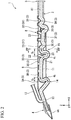
FIG. 2 is a cross-sectional view along arrows II-II ofFIG. 1 . -
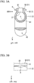
FIG. 3A is a cross-sectional view along arrows III-III ofFIG. 2 . -
FIG. 3B is a partial side view in the direction of arrow IIIb ofFIG. 3A . -
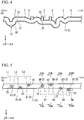
FIG. 4 is a cross-sectional view showing the wind instrument according to another embodiment of the present invention. -
FIG. 5 is a front view showing the wind instrument according to yet another embodiment of the present invention. -
FIG. 6A is a cross-sectional view along arrows VIa-VIa ofFIG. 5 . -
FIG. 6B is a cross-sectional view along arrows VIb-VIb ofFIG. 5 . -
FIG. 6C is a cross-sectional view along arrows VIc-VIc ofFIG. 5 . -
FIG. 7 is a perspective view showing a tone hole tube in the embodiment ofFIG. 5 . -
FIG. 8 is a cross-sectional view along arrows VIII-VIII ofFIG. 5 . -
FIG. 9 is a cross-sectional view showing the tone hole tube of the wind instrument according to another embodiment of the present invention. - Hereinbelow, one embodiment of the present invention will be described referring to
FIGS. 1 to 3 . - As shown in
FIGS. 1 and2 , the wind instrument 1 of the present embodiment is provided with atube body 2, atone hole tube 3, a mouth piece 4 (blow hole), abell 5, and afinger pressing plate 6. Themouthpiece 4 and thebell 5 are disposed at both ends of thetube body 2 in the lengthwise direction (X-axis direction). Themouthpiece 4, which may for example be integrally formed with thetube body 2, in this embodiment is detachably mounted on thetube body 2. Themouthpiece 4, which may be a single reed provided with one sheet-like reed 4A as in the illustrated example, may also for example be an air reed, a lip reed, or a double reed. - In the present embodiment, the lengthwise direction of the
tube body 2 and the like corresponds to the direction, viewed from a performer playing the wind instrument 1, from themouthpiece 4 to thebell 5. In the following description, the lengthwise direction of thetube body 2 is called the X-axis direction, the horizontal direction viewed from the performer is called the Y-axis direction of thetube body 2 and the like, and the vertical direction viewed from the performer is called the Z-axis direction of thetube body 2 and the like, as shown inFIGS. 1 to 3 . - The
tube body 2 may be formed by any one material of for example a wood material, a metal material, and a resin material, and may be formed by for example a material that suitably combines these materials. - The
tube body 2 of the present embodiment is provided with amain tube 11, in which at both ends in the lengthwise direction themouthpiece 4 and thebell 5 are arranged, and anauxiliary tube 12 that is connected to themain tube 11 so as to branch off from themain tube 11. - The
main tube 11 and theauxiliary tube 12 are formed in a cylindrical shape with the inner diameter dimension of each being fixed. Theauxiliary tube 12 is connected to afirst end portion 13 on themouthpiece 4 side of themain tube 11. In the present embodiment, theauxiliary tube 12 is disposed at a region on the upper side (the upper side in the Z-axis direction) of themain tube 11, and extends in the X-axis direction and Z-axis direction with respect to themain tube 11. That is, theauxiliary tube 12 does not extend in the Y-axis direction with respect to themain tube 11. In the present embodiment, theauxiliary tube 12 extends so as to follow the tube axis A1 that passes through the center of the main tube 11 (refer toFIG. 3A ), but is not limited thereto. - As a result of the
tube body 2 being provided with themain tube 11 and theauxiliary tube 12, the wind instrument 1 of the present embodiment has the same acoustic characteristics as the case of thetube body 2 being conical. - The
tone hole tube 3 constitutes the tone hole of the wind instrument 1 of the present embodiment. Thetone hole tube 3 has an inneropen end 21 that opens to the inside (inner periphery) of themain tube 11, and an outeropen end 22 that opens to the outside of themain tube 11. Thetone hole tube 3 is formed in a cylindrical shape with the inner diameter being fixed. - A plurality of the
tone hole tubes 3 are arrayed spaced apart in the X-axis direction of themain tube 11. - The position of the inner
open end 21 of eachtone hole tube 3 along the tube axis A1 of themain tube 11 is set in consideration of the pitch of the wind instrument 1. The inner diameter and axial length of eachtone hole tube 3 are individually set in consideration of the pitch and sound production (for example, volume, sound quality and the like) of the wind instrument 1. That is, the inner diameter and axial length of thetone hole tubes 3 mutually differ for the plurality oftone hole tubes 3. In addition, the inner diameter of some of the tone hole tubes 3 (3A to 3E) is set to a size that allows the outer open ends 22 of thetone hole tubes 3 to be blocked by the fingers of the performer. - In the present embodiment, the plurality of
tone hole tubes 3 are arranged in a row in the X-axis direction of themain tube 11. More specifically, the inner open ends 21 and outer open ends 22 of the plurality oftone hole tubes 3 are disposed at the same position mutually in the Y-axis direction of themain tube 11. Also, the lateral direction (Y-axis direction) of themain tube 11 is not included in the direction in which the plurality oftone hole tubes 3 extend from the main tube 1. In the present embodiment, the plurality oftone hole tubes 3 are all disposed on the upper side (in the Z-axis direction) of themain tube 11. - The plurality of
tone hole tubes 3 each have a portion that extends in the upward direction (Z-axis positive direction) of themain tube 11 with respect to themain tube 11. That is, thetone hole tubes 3A to 3C, 3E, 3F, 3H, and 31 wholly extend straight in the upward direction of themain tube 11. The remainingtone hole tubes main tube 11. - These
tone hole tubes 3 constitute tone holes for pitch operation (pitch tone holes) in which, by being opened and closed, the pitch of the wind instrument 1 changes. - In the present embodiment, the number of the aforementioned
tone hole tubes 3 is nine, and it would be difficult to directly open and close all thetone hole tubes 3 with the performer's fingers. For that reason, the wind instrument 1 of the present embodiment is provided with a key mechanism 8 (key system). - The first to fifth
tone hole tubes 3A to 3E of the ninetone hole tubes 3, counting from thefirst end portion 13 side of themain tube 11, are directly opened by the fingers of the performer. The first to thirdtone hole tubes tone hole tubes - The sixth to ninth
tone hole tubes 3F to 31 are opened and closed by utilizing the key mechanism 8 (key system). Thekey mechanism 8 is operated by the ring finger and little finger of the performer's right hand. - Referring to
FIG. 2 , athumbhole 14 that is opened and closed by the thumb of the left hand of the performer is also formed in themain tube 11. Thethumbhole 14 is formed in themain tube 11 at a position more to thefirst end portion 13 side than thetone hole tube 3A in the X-axis direction of themain tube 11. Thethumbhole 14 of the present embodiment opens to the downward direction of the main tube 11 (negative direction side on the Z axis). The thumbhole 14 changes the pitch of the wind instrument 1 by being opened and closed by a finger of the performer (left hand thumb) similarly to thetone hole tubes 3A to 3E described above. - In the wind instrument 1 of the present embodiment, the
main tube 11 and thetone hole tubes - As shown in
FIG. 2 , themain tube 11 of the present embodiment is curved a plurality of times in the Z-X plane. That is, themain tube 11 meanders in the vertical direction (Z-axis direction) of themain tube 11. In the present embodiment, themain tube 11 does not meander in the lateral direction (Y-axis direction). By themain tube 11 extending in the lengthwise direction (X-axis direction) while curving in the vertical direction (Z-axis direction), the linear length of themain tube 11 in the lengthwise direction (X-axis direction) of themain tube 11 becomes shorter than the length of themain tube 11 along the tube axis A1 of themain tube 11. - The meandering direction of the
main tube 11 may also for example be the lateral direction (Y-axis direction) of themain tube 11. - In the portions where the
main tube 11 bends, the linear distance of the interval between adjacenttone hole tubes 3 in the X-axis direction of themain tube 11 is smaller than the interval between adjacenttone hole tubes 3 in the tube axis A1 of themain tube 11. For example, themain tube 11 curves at the portion positioned between the fourthtone hole tube 3D and the fifthtone hole tube 3E. Thereby, the linear distance s1 of the interval of thetone hole tube 3D and thetone hole tube 3E in the X-axis direction of themain tube 11 is smaller than the length d1 of the interval of thetone hole tube 3D and thetone hole tube 3E along the tube axis A1 of themain tube 11. - The inner
open end 21 of thetone hole tube 3D and the inneropen end 21 of thetone hole tube 3E are connected to themain tube 11 at positions at which the interval along the tube axis becomes the predetermined length d1, such that a predetermined pitch is produced. - Similarly, the
main tube 11 is curved at the portion positioned between the firsttone hole tube 3A that is opened and closed by the index finger of the left hand and the thumbhole 14 that is opened and closed by the thumb of the left hand. Thereby, the linear distance s2 of the interval between thetone hole tube 3A and the thumbhole 14 in the X-axis direction of themain tube 11 is smaller than the length d2 of the interval of thetone hole tube 3A and thethumbhole 14 along the tube axis A1 of themain tube 11. - In the present embodiment, the
main tube 11 meanders in the Z-axis direction. For this reason, there are portions positioned relatively high (in the Z-axis positive direction) and portions positioned relatively low (in the Z-axis negative direction) in themain tube 11. - The
tone hole tubes 3A to 3C, 3E, 3F, 3H, 31 whose lengths in the tube axis direction are comparatively short, are connected to portions of themain tube 11 that are positioned relatively high. On the other hand, thetone hole tubes main tube 11 that are positioned relatively low. Thereby, the outer open ends 22 of the plurality oftone hole tubes 3 are positioned in close proximity to each other in the Z-axis direction of themain tube 11. In the present embodiment, by combining with the curving of sometone hole tubes 3 as described below, the outer open ends 22 of the plurality oftone hole tubes 3 are positioned at the same position in the vertical direction (on the same X-Y plane). - Also, in the present embodiment, by the meandering of the
main tube 11 in the Z-axis direction, adepression portion 15 is formed at a region on the lower side (Z-axis negative direction) of themain tube 11. Thedepression portion 15 is provided near the fourth and fifthtone hole tubes main tube 11. Thedepression portion 15 may be positioned on the lower side of the fifthtone hole tube 3E as illustrated inFIG. 2 , and may for example be positioned between the fourth and fifthtone hole tubes main tube 11. - By placing the right hand thumb of the performer at the
depression portion 15, it is possible to stably hold the wind instrument. - In the wind instrument 1 of the present embodiment, the
tone hole tubes tone hole tubes 3A to 3C, 3E, 3F, 3H, 31 curve to be connected to themain tube 11. That is, thetone hole tubes 3A to 3C, 3E, 3F, 3H, 31 with a comparatively short length along the tube axis extend straight in the upward direction from themain tube 11. Also, thetone hole tubes main tube 11. - In the present embodiment, the
tone hole tubes curved tube portion 23 that changes the direction of the tube axial line of thetone hole tubes tone hole tubes curved tube portion 23 may be a portion of thetone hole tubes FIG. 2 , and for example may be the entirety of thetone hole tubes - The direction of curving of the
tone hole tubes main tube 11 in the present embodiment. That is, thetone hole tubes main tube 11. - As another embodiment, an embodiment is also conceivable in which the tone hole tubes are for example distorted in the Y-axis direction of the
main tube 11. - In the present embodiment, by the curving of the
tone hole tubes open end 22 of the plurality oftone hole tubes 3 is favorably set in consideration of the operability of the wind instrument 1. - For example, by the curving of the fourth
tone hole tube 3D that is blocked by the index finger of the right hand, the outeropen end 22 of thetone hole tube 3D and the outeropen end 22 of the fifthtone hole tube 3E that is blocked by the middle finger of the right hand are positioned in mutual proximity in the X-axis direction and Z-axis direction of themain tube 11. That is, by the bending of thetone hole tube 3D, the outer open ends 22 of the plurality oftone hole tubes - The direction of the inner
open end 21 of thistone hole tube 3D differs from the inner open ends 21 of the othertone hole tubes main tube 11 with respect to the upper side in the height direction of themain tube 11. However, the direction of the outeropen end 22 of thetone hole tube 3D is the Z-axis positive direction (upward direction) of themain tube 11, similarly to the outer open ends 22 of the othertone hole tubes 3. While thetone hole tube 3D may for example be curved a plurality of times, in the present embodiment the fourthtone hole tube 3D is curved only once. - The seventh
tone hole tube 3G that is opened and closed by using thekey mechanism 8 extends in the Z-axis positive direction by being curved from the inneropen end 21 in the X-axis positive direction. Thereby, the intervals in the X-axis direction between the outeropen end 22 of thetone hole tube 3G and the outer open ends 22 of the sixth and eighthtone hole tubes tone hole tube 3G may also meander by being curved a plurality of times. - Also, in the present embodiment, although the
main tube 11 and thetone hole tubes 3 are curved, the vertical positions of the outer open ends 22 of the plurality oftone hole tubes 3A to 3E and the vertical positions of the outer open ends 22 of the plurality oftone hole tubes 3F to 31 mutually align in the Z-axis direction of themain tube 11. In the example shown inFIG. 2 , although the positions in the Z-axis direction of themain tube 11 slightly differ between the outer open ends 22 of thetone hole tubes 3A to 3E that are directly opened and closed by fingers and the outer open ends 22 of thetone hole tubes 3F to 31 that are opened and closed by using thekey mechanism 8, the positions may be made to align. - As shown in
FIGS. 1 to 3 , thefinger pressing plate 6 extends from the outeropen end 22 of thetone hole tube 3 to the outside in the radial direction of thetone hole tubes 3. That is, thefinger pressing plate 6 is a flange that is formed at the outeropen end 22 of thetone hole tube 3. Thefinger pressing plate 6 is disposed spaced apart with respect to the outer periphery of themain tube 11. In the present embodiment, the outeropen end 22 of thetone hole tube 3 faces the upper side (Z-axis positive direction) of themain tube 11. For this reason, thefinger pressing plate 6 extends in the X-axis and Y-axis directions of themain tube 11, which are perpendicular to the vertical direction (Z-axis direction). - In the present embodiment, a common finger
pressing plate 6 is provided for the plurality oftone hole tubes 3. That is, the samefinger pressing plate 6 is provided for the plurality oftone hole tubes 3. - In the present embodiment, since the outer open ends 22 of the plurality of
tone hole tubes 3 are arrayed in the X-axis direction, thefinger pressing plate 6 is formed in a band plate shape extending in the X-axis direction of themain tube 11. Also, in the present embodiment, the dimension of thefinger pressing plate 6 in the Y-axis direction of the main tube 11 (width dimension) is set so as not to protrude from both ends in the Y-axis direction (lateral direction) of themain tube 11, in consideration of the operability by the performer. - The
finger pressing plate 6 should be provided for at least thetone hole tubes 3A to 3E that are directly opened and closed by the fingers, but as shown inFIG. 2 , in the present embodiment thefinger pressing plate 6 is also provided for thetone hole tubes 3F to 31 that are opened and closed by using thekey mechanism 8. - The
finger pressing plate 6 has the surface to which the outeropen end 22 of thetone hole tube 3 opens (opening surface 31). - Among the opening
surface 31 of thefinger pressing plate 6, the region where the outer open ends 22 of thetone hole tubes 3 opened and closed by thekey mechanism 8 are disposed (hereinbelow called the key opening surface 32) is formed to be planar. On the other hand, among the openingsurface 31 of thefinger pressing plate 6, the region where the outer open ends 22 of thetone hole tubes 3 directly opened and closed by fingers are disposed (hereinbelow called the finger opening surface 33) is formed to be curved, as shown inFIG. 3A . - In the present embodiment, the
finger opening surface 33 curves in a convex shape when viewed from the X-axis direction of the main tube 11 (refer toFIG. 3A ), and is formed to be a curved surface that does not curve when viewed from the Y-axis direction of the main tube 11 (refer toFIG. 3B ). Thereby, as shown inFIG. 3B , a dent in which a finger enters is formed at the outeropen end 22 of thetone hole tube 3. - As described above, in the wind instrument 1 of the present embodiment, it is possible to adjust the pitch of the wind instrument 1 by changing the position (position along the tube axis A1) of the inner
open end 21 of thetone hole tube 3 with respect to themain tube 11 and the length in the tube axis direction of the tone hole tube 3 (length dimension of the tone hole). By the curving of themain tube 11 and thetone hole tubes 3, it is possible to suitably adjust the arrangement of the outer open ends 22 of the plurality oftone hole tubes 3 in consideration of operability of the wind instrument 1 so as not to hinder adjustment of pitch. Moreover, since there is no longer a need to use the diameter of the tone holes as the aforementioned main adjustment of pitch, it is possible to effectively utilize the inner diameter of the tone hole tubes 3 (diameter dimension of the tone holes) for sound production of the wind instrument 1. - Further describing these points, although it is possible to adjust the pitch of the wind instrument 1 by changing the inner diameter dimension of the
tone hole tubes 3, in the present embodiment, it is possible to freely change the length of thetone hole tubes 3 along the tube axis without impairing the operability of the wind instrument 1. For this reason, in the wind instrument 1 of the present embodiment, it is possible to sufficiently adjust the pitch of the wind instrument 1 by changing the length of thetone hole tube 3 instead of changing the inner dimeter dimension of thetone hole tube 3. On the other hand, although the sound production of the wind instrument 1 is adjusted by changing the inner diameter dimension of thetone hole tubes 3, in the wind instrument 1 of the present embodiment, since it is not required to use changes of the internal diameter dimension of thetone hole tubes 3 for pitch adjustment, it is possible to suppress the influence of pitch adjustment on adjustment of sound production. - That is, according to the wind instrument 1 of the present embodiment, it is possible to relax restrictions on pitch adjustment, sound production adjustment, and adjustment of the tone hole arrangement in consideration of operability. Accordingly, it is possible to easily ensure both the acoustic performance of the wind instrument 1 and the operability of the wind instrument 1.
- Also, according to the wind instrument 1 of the present embodiment, the plurality of
tone hole tubes 3 each have a portion that extends in the vertical direction (Z-axis direction) of themain tube 11 with respect to themain tube 11, and the meandering direction of themain tube 11 is parallel with the vertical direction of themain tube 11. - For this reason, it is possible to mutually space apart the positions of the inner open ends 21 of the plurality of
tone hole tubes 3 in the vertical direction of themain tube 11. Thereby, even if the lengths along the tube axis of the plurality oftone hole tubes 3 mutually differ, it is possible to mutually approximate the outer open ends 22 of the plurality oftone hole tubes 3 in the vertical direction of themain tube 11. As a result, it is possible to easily block the outer open ends 22 of the plurality oftone hole tubes 3 with a plurality of fingers. That is, it is possible to easily ensure the operability of the wind instrument 1. - In the wind instrument 1 of the present embodiment, by the meandering direction of the
main tube 11 being parallel with the vertical direction of themain tube 11, it is possible to reduce the interval between the firsttone hole tube 3A that is opened and closed by the index finger of the left hand and the thumbhole 14 that is opened and closed by the thumb of the left hand. For this reason, when blocking both the firsttone hole tube 3A and thethumbhole 14, it is possible to grip thetube body 2 in a pinching manner with the left hand thumb and index finger. That is, it is possible for the performer to stably grip the wind instrument 1 and so it is possible to achieve an improvement in the operability of the wind instrument 1. - In the wind instrument 1 of the present embodiment, by the reduction in the interval between the outer open ends 22 of the
tone hole tubes 3 due to the curving of themain tube 11 and thetone hole tubes 3, it is possible to configure thekey mechanism 8 in a compact manner. - Specifically, since it is possible to increase the number of the outer open ends 22 of the
tone hole tubes 3 that can be directly blocked by fingers, it is possible to reduce the number oftone hole tubes 3 that are opened and closed using thekey mechanism 8. That is, it is possible to reduce the number of operators 41 (keys) of thekey mechanism 8. Also, since it is possible to set short the length of theoperators 41 of thekey mechanism 8, it is also possible to achieve an improvement in reliability of the wind instrument 1. - In addition, according to the wind instrument 1 of the present embodiment, by the
main tube 11 meandering in the vertical direction (Z-axis direction), thedepression portion 15 is formed at a region on the lower side of themain tube 11. By the right hand thumb of the performer being placed at thisdepression portion 15, the performer can grip the wind instrument 1 in a stable manner. Also, in the state of the right hand thumb being placed at thedepression portion 15, since the right hand is stably positioned with respect to themain tube 11, it is also possible to perform a stable opening and closing operation of thetone hole tubes 3 with the performer's fingers excluding the right hand thumb. - Also, according to the wind instrument 1 of the present embodiment, since the
tone hole tubes 3 that are curved each have acurved tube portion 23, it is possible to freely and suitably arrange the outer open ends 22 of thetone hole tubes 3 with respect to the inner open ends 21. That is, it is possible to easily ensure the operability of the wind instrument 1. - In the wind instrument 1 of the present embodiment, the
main tube 11 meanders only in the vertical direction, and the plurality oftone hole tubes 3 extend only in the vertical direction (Z-axis direction) and lengthwise direction (X-axis direction) from themain tube 11. The plurality oftone hole tubes 3 are arranged in a row in the lengthwise direction of themain tube 11. - For this reason, it is possible to make the shape of the structure including the
main tube 11 and the plurality of tone hole tubes 3 a symmetrical shape based on the center of themain tube 11 in the lateral direction (Y-axis direction). Thereby, when manufacturing this structure, a pair of separate structures formed in symmetrical shapes, after being molded, may be fixed so as to be bonded together. Accordingly, it is possible to easily manufacture the wind instrument 1. - According to the wind instrument 1 of the present embodiment by the tone hole being constituted by the
tone hole tube 3, it is possible to set the thickness of the tube wall of thetube body 2 without consideration to the length of the tone hole. Thereby, it is possible to thinly form the tube wall of thetube body 2. Accordingly, it is possible to economize resources for constituting the wind instrument 1 and it is possible to achieve a reduction in weight of the wind instrument 1. - Since the wind instrument 1 of the present embodiment is provided with the
finger pressing plate 6, the performer can easily judge by the sense of touch of a finger whether the outeropen end 22 of thetone hole tube 3 is correctly blocked by the finger. Hereinbelow, this point is explained in detail. - In the case of no
finger pressing plate 6, when the performer blocks the outeropen end 22 of thetone hole tube 3 with his own finger, the finger of the performer may touch not only the inner edge of the outeropen end 22 but also the outer edge, with these feelings all being transmitted to the finger of the performer. For this reason, it is difficult for the performer to judge whether the outeropen end 22 of thetone hole tube 3 is correctly blocked. - In contrast to this, in the case of the
finger pressing plate 6 being present, when blocking the outeropen end 22 of thetone hole tube 3 with a finger, the finger makes no contact with the outer edge of the outeropen end 22. Thereby, the performer easily ascertains the inner edge of the outeropen end 22 of thetone hole tube 3 by the feeling of the finger. That is, the performer can easily judge by the feeling of the finger whether the outeropen end 22 of thetone hole tube 3 is correctly blocked by the finger. - In addition, in the wind instrument 1 of the present embodiment equipped with the
finger pressing plate 6, when a finger of the performer is not blocking the outeropen end 22 of thetone hole tube 3, it is also possible to place the finger on the openingsurface 31 of the finger pressing plate 6 (in particular, the finger opening surface 33). For this reason, the performer can easily move his fingers from a position that does not block the outer open ends 22 of thetone hole tubes 3 to a position that does block the outer open ends 22 of thetone hole tubes 3. - Also, since the wind instrument 1 of the present embodiment is provided with the
finger pressing plate 6, the performer can easily perform the operation that blocks the outer open ends 22 of thetone hole tubes 3 with his own fingers. Hereinbelow, this point is described in detail. - In the case of no
finger pressing plate 6, in the event of the performer attempting to block the outeropen end 22 of thetone hole tube 3 with his own finger, when the finger of the performer becomes separated from the outeropen end 22 of thetone hole tube 3, the finger becomes positioned on the outer periphery of thetone hole tube 3. In this case, it is necessary to lift the finger from the outer periphery of thetone hole tube 3 and move the finger to the position blocking the outeropen end 22 of thetone hole tube 3, and so the operability of the wind instrument 1 is not necessarily favorable. - In contrast to this, in the case of the
finger pressing plate 6 being present, even if a finger of the performer becomes separated from the outeropen end 22 of thetone hole tube 3, since the finger abuts thefinger opening surface 33 of thefinger pressing plate 6, the finger need only be moved along thefinger opening surface 33 to the outeropen end 22. That is, since the need to lift the finger is eliminated, even if the finger of the performer becomes separated from the outeropen end 22 of thetone hole tube 3, the performer can easily perform the operation of blocking the outeropen end 22 of thetone hole tube 3 with his own finger. - From the above, according to the wind instrument 1 of the present embodiment, it is possible to ensure the operability of the wind instrument 1 by the performer with the presence of the
finger pressing plate 6. - Also, according to the wind instrument 1 of the present embodiment, the same
finger pressing plate 6 is provided for the plurality oftone hole tubes 3. For this reason, the edge portion at the distal end in the extending direction of the finger pressing plate 6 (the region corresponding to the edge of the finger opening surface 33) is not located between the outer open ends 22 of adjacenttone hole tubes 3. For this reason, it is possible to lower the possibility of a finger of the performer touching the edge portion at the distal end in the extending direction of thefinger pressing plate 6. Thereby, the performer can further easily ascertain whether the outeropen end 22 of thetone hole tube 3 is correctly blocked by a finger with the feeling of the finger. - Also, according to the wind instrument 1 of the present embodiment, the gap between adjacent
tone hole tubes 3 is covered by thefinger pressing plate 6. For that reason, when the performer tries to block the outeropen end 22 of thetone hole tube 3 with that finger, even if the performer's finger becomes separated from the outeropen end 22 of thetone hole tube 3, it is possible to prevent the performer's finger from entering the gap between adjacenttone hole tubes 3. Thereby, even if the performer's finger is separated from the outeropen end 22 of thetone hole tube 3, the need to lift the finger is eliminated, and the performer can easily perform the operation of blocking the outeropen end 22 of thetone hole tube 3 with his own finger. - From the above, by the same
finger pressing plate 6 being provided for the plurality oftone hole tubes 3, it is possible to more favorably ensure the operability of the wind instrument 1 by the performer. - By the same
finger pressing plate 6 being provided for the plurality oftone hole tubes 3, in the case of fabricating thetube body 2 of the wind instrument 1, thetone hole tubes 3 and thefinger pressing plate 6 by resin molding, compared to the case of thefinger pressing plate 6 being provided for eachtone hole tube 6, it is possible to achieve a simplification of the mold shape. Thereby, it is possible to easily manufacture the wind instrument 1. Also, it is possible to achieve a reduction in the manufacturing cost of the wind instrument 1. - According to the wind instrument 1 of the present embodiment, since the
finger opening surface 33 of thefinger pressing plate 6 is formed into a curved surface, the performer can correctly and easily block the outeropen end 22 of thetone hole tube 3 with a finger. Specifically, by thefinger opening surface 33 of thefinger pressing plate 6 being formed into a curved surface, a dent shape in which the finger enters is formed at the outeropen end 22 of thetone hole tube 3. For this reason, the performer can correctly and easily block the outeropen end 22 of thetone hole tube 3 by causing the finger to enter the outeropen end 22 made to have a dent shape. - Although the present invention was described in detail above, the present invention is not limited to the aforementioned embodiments, and various modifications can be made within a scope that does not depart from the gist of the present invention.
- The wind instrument of the present invention is not limited to one that includes the
key mechanism 8. and may be applied to a wind instrument of a type in which all of thetone hole tubes 3 are directly opened and closed by fingers, as shown for example inFIG. 4 and FIG. 5 . - In the wind instrument of the present invention, the
finger pressing plate 6 may for example be individually provided for the plurality oftone hole tubes 3. That is, the wind instrument may be provided with a plurality of fingerpressing plates 6. In addition, the wind instrument of the present invention may not be provided with thefinger pressing plate 6 as shown for example inFIGS. 4 to 9 . - In the wind instrument of the present invention, at least one of the
main tube 11 and thetone hole tubes 3 should be curved. - In the constitution shown in
FIG. 4 , only themain tube 11 is curved, while thetone hole tubes 3 are not curved. As shown inFIG. 4 , even if only themain tube 11 is curved, it is possible to ensure the operability of the wind instrument by reducing the interval between the outer open ends 22 of thetone hole tubes 3. - On the other hand, in the constitution illustrated in
FIG. 5 ,FIG. 6A, FIG. 6B, FIG. 6C ,FIG. 7, and FIG. 8 , only thetone hole tube 3 is curved, while themain tube 11 is not curved. Even if only thetone hole tube 3 is curved, due to the curving of thetone hole tube 3 so as to extend in the lengthwise direction of themain tube 11, it is possible to ensure the operability of the wind instrument by reducing the interval between the outer open ends 22 of thetone hole tubes 3. - In the case of the
main tube 11 meandering by being curved a plurality of times, the meandering direction of themain tube 11 is not limited to the vertical direction (Z-axis direction) of themain tube 11 as illustrated inFIGS. 2 and4 , and should at least be a direction orthogonal to the lengthwise direction (X-axis direction) of themain tube 11. That is, the meandering direction of themain tube 11 may also for example be the lateral direction (Y-axis direction) of themain tube 11. - In the case of the
tone hole tube 3 being curved, as shown for example inFIG. 6A, FIG. 6B , andFIG. 8 , thetone hole tube 3 may be curved so that the outeropen end 22 of thetone hole tube 3 is shifted in position in the lateral direction (Y-axis direction) of themain tube 11 with respect to the inneropen end 21. Also, thetone hole tube 3 may be curved so that the direction of the outeropen end 22 differs from the direction of the inneropen end 21. - The inner open ends 21 of the plurality of
tone hole tubes 3 may also mutually be disposed at mutually different positions in the circumferential direction of themain tube 11, as shown for example inFIGS. 5 to 8 . - The outer open ends 22 of the plurality of
tone hole tubes 3 may also be disposed at mutually different positions in the lateral direction (Y-axis direction) of themain tube 11, as shown for example inFIGS. 5 to 8 . In the constitution illustrated inFIG. 5 , the outer open ends 22 of the plurality oftone hole tubes 3 are positioned in a manner mutually shifted in the lateral direction of themain tube 11 in accordance with the lengths of the mutually different fmgers L1 to L3, R1 to R4. - Described in detail, the first to third
tone hole tubes 3J to 3L, counting from thefirst end portion 13 side of themain tube 11, correspond to the index finger L1, the middle finger L2, and the ring finger L3, respectively, of the left hand of the performer. For that reason, the secondtone hole tube 3K is positioned in a manner shifted to the right side (the Y-axis negative direction side inFIG. 5 ) of themain tube 11 with respect to the first and thirdtone hole tubes - On the other hand, the fourth to seventh
tone hole tubes 3M to 3P, counting from the first end portion side of themain tube 11, correspond to the index finger R1, the middle finger R2, the ring finger R3, and the little finger R4, respectively, of the right hand of the performer. For that reason, the fifthtone hole tube 3N is positioned in a manner shifted to the left side (the Y-axis positive direction side inFIG. 5 ) of themain tube 11 with respect to the fourth, sixth, and seventhtone hole tubes tone hole tube 3P is positioned in a manner shifted to the right side (the Y-axis negative direction side inFIG. 5 ) of themain tube 11 with respect to the fourth to sixthtone hole tubes 3M to 3O, so as to be positioned the nearest to the base of the finger R4 of the right hand. - The outer open ends 22 of the plurality of
tone hole tubes 3 may for example be disposed at mutually different positions in the vertical direction (Z-axis direction) of themain tube 11. Also, the directions of the outer open ends 22 of the plurality oftone hole tubes 3 may mutually differ. - Although the
tone hole tube 3 may as shown for example inFIG. 6A, FIG. 6B , andFIG. 8 have thecurved tube portion 23 that changes the direction of the tube axis A2 of thetone hole tube 3 midway in the axial direction of thetone hole tube 3, as shown for example inFIG. 9 , the tube axis A2 of thetone hole tube 3 may also have aninclined tube portion 24 that is inclined with respect to the radial direction of themain tube 11. In this case, the tube axis A2 of eachtone hole tube 3 should extend in a direction inclined to the radial direction of themain tube 11 so that the outer open ends 22 of the plurality oftone hole tubes 3 have positions corresponding to the fingers that block them. - The
inclined tube portion 24 may constitute the entirety of thetone hole tube 3 as illustrated inFIG. 9 , and may for example constitute a portion of thetone hole tube 3. Accordingly, thetone hole tube 3 may have for example both thecurved tube portion 23 and theinclined tube portion 24. - The direction in which the
tone hole tube 3 is inclined by theinclined tube portion 24 may be arbitrary. The direction in which thetone hole tube 3 is inclined may be set so that, as shown for example inFIG. 9 , the outeropen end 22 of thetone hole tube 3 is positioned in a manner shifted in the circumferential direction of themain tube 11 with respect to the inneropen end 21. Also, the direction in which thetone hole tube 3 is inclined may be set so that for example the outeropen end 22 of thetone hole tube 3 is positioned in a manner shifted in the tube axis or lengthwise direction of themain tube 11 with respect to the inneropen end 21. - Even in the case of the
tone hole tube 3 having theinclined tube portion 24, it is possible to freely and suitably arrange the outer open ends 22 of thetone hole tubes 3 with respect to the inner open ends 21. That is, it is possible to easily ensure the operability of the wind instrument 1. - The
thumbhole 14 may be constituted by atone hole tube 30 extending from the outer circumference of themain tube 11 similarly to the pitch tone holes, as shown for example inFIG. 4 . - The
tube body 2 of the wind instrument may be arbitrarily constituted. That is, thetube body 2 may be constituted by only themain tube 11 without being provided with for example theauxiliary tube 12. In this case, the tube body 2 (main tube 11) is not limited to a cylindrical shape, and may for example be formed in for example a conical tube shape. -
- 1, 2: Wind instrument
- 2: Tube body
- 3, 3A, 3B, 3C, 3D, 3E, 3F, 3G, 3H, 31, 3J, 3K, 3L, 3M, 3N, 3O, 3P, 30: Tone hole tube
- 4: Mouthpiece
- 5: Bell
- 6: Finger pressing plate
- 8: Key mechanism
- 11: Main tube
- 12: Auxiliary tube
- 21: Inner open end
- 22: Outer open end
- 23: Curved tube portion
- 24: Inclined tube portion
- 31: Opening surface
- A1: Tube axis of main tube
- A2: Tube axis of tone hole tube
Claims (5)
- A wind instrument comprising:a tube body; anda plurality of tone hole tubes each having an outer open end formed at the outer periphery of the tube body and an inner open end formed through the outer opening end and opening to the inside of the tube body,wherein at least one of the tube body and the tone hole tubes is curved such that the plurality of outer open ends of the plurality of tone hole tubes are disposed so as to be in positions corresponding to respective fingers of the performer, and the plurality of inner open ends are connected at positions that cause the tube body to produce a predetermined pitch.
- The wind instrument according to claim 1, wherein the plurality of tone hole tubes have portions extending in the upward direction of the tube body with respect to the tube body and that are mutually parallel, and
the tube body extends in the lengthwise direction of the tube body while curving a plurality of times in the vertical direction of the tube body. - The wind instrument according to claim 1 or 2, wherein the tone hole tube has an inclined tube portion in which the tube axis of the tone hole tube is inclined with respect to the radial direction of the tube body.
- The wind instrument according to claim 1 or 2, wherein at least two outer open ends are in nearly the same position in the vertical direction of the tube body.
- A wind instrument comprising:a tube body; anda plurality of tone hole tubes each having an outer open end formed at the outer periphery of the tube body and an inner open end formed through the outer opening end and opening to the inside of the tube body,wherein the tone hole tube has an inclined tube portion in which the tube axis of the tone hole tube is inclined with respect to the radial direction of the tube body such that the plurality of outer open ends of the plurality of tone hole tubes are disposed so as to be in positions corresponding to respective fingers of the performer, and the plurality of inner open ends are connected at positions that cause the tube body to produce a predetermined pitch.
Applications Claiming Priority (2)
| Application Number | Priority Date | Filing Date | Title |
|---|---|---|---|
| JP2015192843A JP6679866B2 (en) | 2015-09-30 | 2015-09-30 | Wind instrument |
| PCT/JP2016/077660 WO2017057088A1 (en) | 2015-09-30 | 2016-09-20 | Wind instrument |
Publications (3)
| Publication Number | Publication Date |
|---|---|
| EP3358564A1 true EP3358564A1 (en) | 2018-08-08 |
| EP3358564A4 EP3358564A4 (en) | 2019-06-05 |
| EP3358564B1 EP3358564B1 (en) | 2021-12-15 |
Family
ID=58423688
Family Applications (1)
| Application Number | Title | Priority Date | Filing Date |
|---|---|---|---|
| EP16851262.2A Active EP3358564B1 (en) | 2015-09-30 | 2016-09-20 | Wind instrument |
Country Status (5)
| Country | Link |
|---|---|
| US (1) | US10199017B2 (en) |
| EP (1) | EP3358564B1 (en) |
| JP (1) | JP6679866B2 (en) |
| CN (1) | CN108140366B (en) |
| WO (1) | WO2017057088A1 (en) |
Cited By (1)
| Publication number | Priority date | Publication date | Assignee | Title |
|---|---|---|---|---|
| US12403356B2 (en) | 2020-08-06 | 2025-09-02 | Duke University | Voice therapy device and system |
Families Citing this family (7)
| Publication number | Priority date | Publication date | Assignee | Title |
|---|---|---|---|---|
| JP6679866B2 (en) * | 2015-09-30 | 2020-04-15 | ヤマハ株式会社 | Wind instrument |
| CN108140367B (en) * | 2015-09-30 | 2021-12-28 | 雅马哈株式会社 | Wind musical instrument |
| EP3428910B1 (en) * | 2016-03-07 | 2023-04-12 | Yamaha Corporation | Wind instrument |
| CN109036344B (en) * | 2018-08-21 | 2023-04-07 | 昆明理工大学 | Vertical blowing bamboo flute |
| US11127382B1 (en) | 2020-06-13 | 2021-09-21 | Richard Ruggles | Tone-altering apparatus and method for musical wind instruments |
| USD996517S1 (en) * | 2020-09-17 | 2023-08-22 | Wanne Inc. | Mouthpiece for instrument with aligned ligature holes |
| USD1030854S1 (en) * | 2021-11-02 | 2024-06-11 | Yamaha Corporation | Wind instrument |
Family Cites Families (44)
| Publication number | Priority date | Publication date | Assignee | Title |
|---|---|---|---|---|
| US968694A (en) | 1908-03-14 | 1910-08-30 | C G Conn Co | Tubing for wind instruments. |
| US1455440A (en) | 1922-02-16 | 1923-05-15 | Hofinger Florent | Process of manufacturing flutes |
| US1761329A (en) * | 1928-05-07 | 1930-06-03 | Frank Holton & Company | Wind musical instrument |
| US1809380A (en) * | 1928-10-12 | 1931-06-09 | Conn Ltd C G | Clarinet and the method of manufacture thereof |
| US1801690A (en) | 1930-02-06 | 1931-04-21 | Pruefer Gustav | Musical instrument |
| US3062084A (en) * | 1960-03-24 | 1962-11-06 | Thomas S Ogilvie | Bass flute |
| US3487742A (en) | 1968-03-01 | 1970-01-06 | Warren L Mills | Inner tone for a musical instrument |
| GB1182919A (en) * | 1969-01-22 | 1970-03-04 | George Raw Robinson | An Improvement in Wind Instruments of the Flute Family. |
| US3805665A (en) | 1971-06-21 | 1974-04-23 | Nippon Musical Instruments Mfg | Wind type musical instrument |
| US3722348A (en) | 1972-05-01 | 1973-03-27 | H Visser | Wind instrument |
| US3866507A (en) | 1973-07-26 | 1975-02-18 | Raoul J Eajardo | Noncircular head joint for a concert flute and method of manufacture |
| JPS50137025U (en) | 1974-04-26 | 1975-11-12 | ||
| JPS5839511Y2 (en) | 1975-10-20 | 1983-09-06 | ニシカワ ヒデトシ | plastic beetle |
| JPS6013199B2 (en) | 1978-03-01 | 1985-04-05 | 信男 外山 | wind instruments |
| JPS5533178A (en) | 1978-08-31 | 1980-03-08 | Takamura Toyama | Acoustic hole device for plastic flute |
| FI872561A7 (en) | 1987-06-08 | 1989-03-07 | Kaehoenen Matti | A wind instrument body structure and a method for manufacturing a wind instrument body having said structure. |
| JPH02107198U (en) | 1989-02-15 | 1990-08-27 | ||
| US5309806A (en) | 1991-10-28 | 1994-05-10 | Stavash John C | Woodwind musical instrument |
| JPH0583796U (en) * | 1992-04-10 | 1993-11-12 | 一己 遠藤 | Recorder |
| USD360904S (en) * | 1994-01-10 | 1995-08-01 | Schilling Samuel D | Toy musical instrument |
| JP3116845B2 (en) | 1996-12-06 | 2000-12-11 | ヤマハ株式会社 | bassoon |
| US6852917B2 (en) | 2001-10-16 | 2005-02-08 | Mcaleenan Michael | Construction and method of wind musical instrument |
| US20040111865A1 (en) | 2002-12-13 | 2004-06-17 | Jay Craig | Method and apparatus of forming a bagpipe chanter |
| US7459621B2 (en) | 2006-08-02 | 2008-12-02 | Straubinger David J | Pad assembly for woodwinds, particularly flutes |
| CN201035955Y (en) * | 2007-05-28 | 2008-03-12 | 李青山 | Bass xiao-flute |
| CN101409069B (en) * | 2007-10-12 | 2010-12-08 | 天津市津宝乐器有限公司 | Double bass saxophone |
| ATE525718T1 (en) | 2008-06-27 | 2011-10-15 | Ernst Reisner | HANDLE MECHANICS FOR WOODWIND INSTRUMENTS |
| CN101339761A (en) * | 2008-08-07 | 2009-01-07 | 云南聂耳音乐基金会 | Chimney flute |
| US9208758B2 (en) | 2008-12-12 | 2015-12-08 | University Of Washington | Unified octave/register key and vent for musical wind instruments |
| AT507799B1 (en) * | 2009-04-01 | 2010-08-15 | Werner Tomasi | FLUTE |
| CN201518217U (en) * | 2009-10-14 | 2010-06-30 | 黄朝庆 | Bend pipe vertical bamboo flute |
| JP2011186443A (en) * | 2010-02-12 | 2011-09-22 | Yamaha Corp | Pipe structure of wind instrument |
| EP2360674A2 (en) | 2010-02-12 | 2011-08-24 | Yamaha Corporation | Pipe structure of wind instrument |
| DE102011010124B4 (en) | 2010-07-17 | 2014-09-25 | Anton Braun | Conical C-foot piccolo with a thumb hole |
| JP5619166B2 (en) * | 2010-08-20 | 2014-11-05 | 株式会社Backs Verse | Saxophone |
| US8273975B2 (en) * | 2010-08-30 | 2012-09-25 | Barbara Gisler | Flute |
| JP4995956B2 (en) * | 2010-09-15 | 2012-08-08 | トマジ ヴェルナー | flute |
| NL2005597C2 (en) * | 2010-10-29 | 2012-05-02 | Eibert Johannes Kuijt | MUSIC INSTRUMENT. |
| JP2013213952A (en) | 2012-04-02 | 2013-10-17 | Kaori Isoguchi | Wind instrument, formation method of sound hole, and sound hole formation pad |
| JP6148998B2 (en) * | 2013-07-22 | 2017-06-14 | 道夫 高嶋 | Recorder and ring-shaped member used therefor |
| CN204102553U (en) * | 2014-07-30 | 2015-01-14 | 陈强岑 | A kind of bass bend pipe vertical bamboo flute |
| HK1204430A2 (en) | 2014-09-25 | 2015-11-13 | Nuvo Instrumental (Asia) Limited | A key member for a musical instrument |
| WO2016129063A1 (en) | 2015-02-10 | 2016-08-18 | 株式会社オフィス樹エージェンシー | Breath pressure adjustment damper for ocarina and two-stage attachment adapter |
| JP6679866B2 (en) * | 2015-09-30 | 2020-04-15 | ヤマハ株式会社 | Wind instrument |
-
2015
- 2015-09-30 JP JP2015192843A patent/JP6679866B2/en active Active
-
2016
- 2016-09-20 WO PCT/JP2016/077660 patent/WO2017057088A1/en not_active Ceased
- 2016-09-20 US US15/754,369 patent/US10199017B2/en active Active
- 2016-09-20 EP EP16851262.2A patent/EP3358564B1/en active Active
- 2016-09-20 CN CN201680056474.5A patent/CN108140366B/en active Active
Cited By (1)
| Publication number | Priority date | Publication date | Assignee | Title |
|---|---|---|---|---|
| US12403356B2 (en) | 2020-08-06 | 2025-09-02 | Duke University | Voice therapy device and system |
Also Published As
| Publication number | Publication date |
|---|---|
| WO2017057088A1 (en) | 2017-04-06 |
| EP3358564A4 (en) | 2019-06-05 |
| CN108140366B (en) | 2021-12-31 |
| EP3358564B1 (en) | 2021-12-15 |
| JP6679866B2 (en) | 2020-04-15 |
| US20180254026A1 (en) | 2018-09-06 |
| US10199017B2 (en) | 2019-02-05 |
| JP2017067994A (en) | 2017-04-06 |
| CN108140366A (en) | 2018-06-08 |
Similar Documents
| Publication | Publication Date | Title |
|---|---|---|
| EP3358564B1 (en) | Wind instrument | |
| EP3971884B1 (en) | Wind instrument | |
| US10497343B2 (en) | Reed for a musical instrument | |
| US8395038B2 (en) | Pick for an instrument | |
| JP2016505892A (en) | Fluid flow control valve | |
| JP2012118386A (en) | Wind instrument | |
| US20240428764A1 (en) | Keyboard device and method for guiding key | |
| US11295711B2 (en) | Percussion instrument with at least two tone bars | |
| CN108701442B (en) | wind instrument | |
| CN223857856U (en) | Multifunctional nine-tone hole wind instrument | |
| TWI753638B (en) | Brass instrument | |
| US20240428765A1 (en) | Keyboard device and method for guiding key | |
| US9413865B2 (en) | Handheld electronic device | |
| US1103555A (en) | Wood wind instrument. | |
| KR102081000B1 (en) | Ocarina | |
| JP6657793B2 (en) | Wind instrument | |
| CN114937445A (en) | Double-reed wind instrument | |
| CN104704553A (en) | Keyboard harmonica and hose with mouthpiece | |
| KR20130006960U (en) | Saxophone's Tube Protector |
Legal Events
| Date | Code | Title | Description |
|---|---|---|---|
| STAA | Information on the status of an ep patent application or granted ep patent |
Free format text: STATUS: THE INTERNATIONAL PUBLICATION HAS BEEN MADE |
|
| PUAI | Public reference made under article 153(3) epc to a published international application that has entered the european phase |
Free format text: ORIGINAL CODE: 0009012 |
|
| STAA | Information on the status of an ep patent application or granted ep patent |
Free format text: STATUS: REQUEST FOR EXAMINATION WAS MADE |
|
| 17P | Request for examination filed |
Effective date: 20180313 |
|
| AK | Designated contracting states |
Kind code of ref document: A1 Designated state(s): AL AT BE BG CH CY CZ DE DK EE ES FI FR GB GR HR HU IE IS IT LI LT LU LV MC MK MT NL NO PL PT RO RS SE SI SK SM TR |
|
| AX | Request for extension of the european patent |
Extension state: BA ME |
|
| DAV | Request for validation of the european patent (deleted) | ||
| DAX | Request for extension of the european patent (deleted) | ||
| A4 | Supplementary search report drawn up and despatched |
Effective date: 20190508 |
|
| RIC1 | Information provided on ipc code assigned before grant |
Ipc: G10D 7/02 20060101ALI20190502BHEP Ipc: G10D 7/00 20060101ALI20190502BHEP Ipc: G10D 9/00 20060101AFI20190502BHEP Ipc: G10D 7/06 20060101ALI20190502BHEP |
|
| STAA | Information on the status of an ep patent application or granted ep patent |
Free format text: STATUS: EXAMINATION IS IN PROGRESS |
|
| 17Q | First examination report despatched |
Effective date: 20210409 |
|
| GRAP | Despatch of communication of intention to grant a patent |
Free format text: ORIGINAL CODE: EPIDOSNIGR1 |
|
| STAA | Information on the status of an ep patent application or granted ep patent |
Free format text: STATUS: GRANT OF PATENT IS INTENDED |
|
| INTG | Intention to grant announced |
Effective date: 20210712 |
|
| GRAS | Grant fee paid |
Free format text: ORIGINAL CODE: EPIDOSNIGR3 |
|
| GRAA | (expected) grant |
Free format text: ORIGINAL CODE: 0009210 |
|
| STAA | Information on the status of an ep patent application or granted ep patent |
Free format text: STATUS: THE PATENT HAS BEEN GRANTED |
|
| AK | Designated contracting states |
Kind code of ref document: B1 Designated state(s): AL AT BE BG CH CY CZ DE DK EE ES FI FR GB GR HR HU IE IS IT LI LT LU LV MC MK MT NL NO PL PT RO RS SE SI SK SM TR |
|
| REG | Reference to a national code |
Ref country code: GB Ref legal event code: FG4D Ref country code: CH Ref legal event code: EP |
|
| REG | Reference to a national code |
Ref country code: IE Ref legal event code: FG4D Ref country code: DE Ref legal event code: R096 Ref document number: 602016067485 Country of ref document: DE |
|
| REG | Reference to a national code |
Ref country code: AT Ref legal event code: REF Ref document number: 1456084 Country of ref document: AT Kind code of ref document: T Effective date: 20220115 |
|
| REG | Reference to a national code |
Ref country code: LT Ref legal event code: MG9D |
|
| REG | Reference to a national code |
Ref country code: NL Ref legal event code: MP Effective date: 20211215 |
|
| PG25 | Lapsed in a contracting state [announced via postgrant information from national office to epo] |
Ref country code: RS Free format text: LAPSE BECAUSE OF FAILURE TO SUBMIT A TRANSLATION OF THE DESCRIPTION OR TO PAY THE FEE WITHIN THE PRESCRIBED TIME-LIMIT Effective date: 20211215 Ref country code: LT Free format text: LAPSE BECAUSE OF FAILURE TO SUBMIT A TRANSLATION OF THE DESCRIPTION OR TO PAY THE FEE WITHIN THE PRESCRIBED TIME-LIMIT Effective date: 20211215 Ref country code: FI Free format text: LAPSE BECAUSE OF FAILURE TO SUBMIT A TRANSLATION OF THE DESCRIPTION OR TO PAY THE FEE WITHIN THE PRESCRIBED TIME-LIMIT Effective date: 20211215 Ref country code: BG Free format text: LAPSE BECAUSE OF FAILURE TO SUBMIT A TRANSLATION OF THE DESCRIPTION OR TO PAY THE FEE WITHIN THE PRESCRIBED TIME-LIMIT Effective date: 20220315 |
|
| REG | Reference to a national code |
Ref country code: AT Ref legal event code: MK05 Ref document number: 1456084 Country of ref document: AT Kind code of ref document: T Effective date: 20211215 |
|
| PG25 | Lapsed in a contracting state [announced via postgrant information from national office to epo] |
Ref country code: SE Free format text: LAPSE BECAUSE OF FAILURE TO SUBMIT A TRANSLATION OF THE DESCRIPTION OR TO PAY THE FEE WITHIN THE PRESCRIBED TIME-LIMIT Effective date: 20211215 Ref country code: NO Free format text: LAPSE BECAUSE OF FAILURE TO SUBMIT A TRANSLATION OF THE DESCRIPTION OR TO PAY THE FEE WITHIN THE PRESCRIBED TIME-LIMIT Effective date: 20220315 Ref country code: LV Free format text: LAPSE BECAUSE OF FAILURE TO SUBMIT A TRANSLATION OF THE DESCRIPTION OR TO PAY THE FEE WITHIN THE PRESCRIBED TIME-LIMIT Effective date: 20211215 Ref country code: HR Free format text: LAPSE BECAUSE OF FAILURE TO SUBMIT A TRANSLATION OF THE DESCRIPTION OR TO PAY THE FEE WITHIN THE PRESCRIBED TIME-LIMIT Effective date: 20211215 Ref country code: GR Free format text: LAPSE BECAUSE OF FAILURE TO SUBMIT A TRANSLATION OF THE DESCRIPTION OR TO PAY THE FEE WITHIN THE PRESCRIBED TIME-LIMIT Effective date: 20220316 |
|
| PG25 | Lapsed in a contracting state [announced via postgrant information from national office to epo] |
Ref country code: NL Free format text: LAPSE BECAUSE OF FAILURE TO SUBMIT A TRANSLATION OF THE DESCRIPTION OR TO PAY THE FEE WITHIN THE PRESCRIBED TIME-LIMIT Effective date: 20211215 |
|
| PG25 | Lapsed in a contracting state [announced via postgrant information from national office to epo] |
Ref country code: SM Free format text: LAPSE BECAUSE OF FAILURE TO SUBMIT A TRANSLATION OF THE DESCRIPTION OR TO PAY THE FEE WITHIN THE PRESCRIBED TIME-LIMIT Effective date: 20211215 Ref country code: SK Free format text: LAPSE BECAUSE OF FAILURE TO SUBMIT A TRANSLATION OF THE DESCRIPTION OR TO PAY THE FEE WITHIN THE PRESCRIBED TIME-LIMIT Effective date: 20211215 Ref country code: RO Free format text: LAPSE BECAUSE OF FAILURE TO SUBMIT A TRANSLATION OF THE DESCRIPTION OR TO PAY THE FEE WITHIN THE PRESCRIBED TIME-LIMIT Effective date: 20211215 Ref country code: PT Free format text: LAPSE BECAUSE OF FAILURE TO SUBMIT A TRANSLATION OF THE DESCRIPTION OR TO PAY THE FEE WITHIN THE PRESCRIBED TIME-LIMIT Effective date: 20220418 Ref country code: ES Free format text: LAPSE BECAUSE OF FAILURE TO SUBMIT A TRANSLATION OF THE DESCRIPTION OR TO PAY THE FEE WITHIN THE PRESCRIBED TIME-LIMIT Effective date: 20211215 Ref country code: EE Free format text: LAPSE BECAUSE OF FAILURE TO SUBMIT A TRANSLATION OF THE DESCRIPTION OR TO PAY THE FEE WITHIN THE PRESCRIBED TIME-LIMIT Effective date: 20211215 Ref country code: CZ Free format text: LAPSE BECAUSE OF FAILURE TO SUBMIT A TRANSLATION OF THE DESCRIPTION OR TO PAY THE FEE WITHIN THE PRESCRIBED TIME-LIMIT Effective date: 20211215 |
|
| PG25 | Lapsed in a contracting state [announced via postgrant information from national office to epo] |
Ref country code: PL Free format text: LAPSE BECAUSE OF FAILURE TO SUBMIT A TRANSLATION OF THE DESCRIPTION OR TO PAY THE FEE WITHIN THE PRESCRIBED TIME-LIMIT Effective date: 20211215 Ref country code: AT Free format text: LAPSE BECAUSE OF FAILURE TO SUBMIT A TRANSLATION OF THE DESCRIPTION OR TO PAY THE FEE WITHIN THE PRESCRIBED TIME-LIMIT Effective date: 20211215 |
|
| REG | Reference to a national code |
Ref country code: DE Ref legal event code: R097 Ref document number: 602016067485 Country of ref document: DE |
|
| PG25 | Lapsed in a contracting state [announced via postgrant information from national office to epo] |
Ref country code: IS Free format text: LAPSE BECAUSE OF FAILURE TO SUBMIT A TRANSLATION OF THE DESCRIPTION OR TO PAY THE FEE WITHIN THE PRESCRIBED TIME-LIMIT Effective date: 20220415 |
|
| PLBE | No opposition filed within time limit |
Free format text: ORIGINAL CODE: 0009261 |
|
| STAA | Information on the status of an ep patent application or granted ep patent |
Free format text: STATUS: NO OPPOSITION FILED WITHIN TIME LIMIT |
|
| PG25 | Lapsed in a contracting state [announced via postgrant information from national office to epo] |
Ref country code: DK Free format text: LAPSE BECAUSE OF FAILURE TO SUBMIT A TRANSLATION OF THE DESCRIPTION OR TO PAY THE FEE WITHIN THE PRESCRIBED TIME-LIMIT Effective date: 20211215 Ref country code: AL Free format text: LAPSE BECAUSE OF FAILURE TO SUBMIT A TRANSLATION OF THE DESCRIPTION OR TO PAY THE FEE WITHIN THE PRESCRIBED TIME-LIMIT Effective date: 20211215 |
|
| 26N | No opposition filed |
Effective date: 20220916 |
|
| PG25 | Lapsed in a contracting state [announced via postgrant information from national office to epo] |
Ref country code: SI Free format text: LAPSE BECAUSE OF FAILURE TO SUBMIT A TRANSLATION OF THE DESCRIPTION OR TO PAY THE FEE WITHIN THE PRESCRIBED TIME-LIMIT Effective date: 20211215 |
|
| PG25 | Lapsed in a contracting state [announced via postgrant information from national office to epo] |
Ref country code: MC Free format text: LAPSE BECAUSE OF FAILURE TO SUBMIT A TRANSLATION OF THE DESCRIPTION OR TO PAY THE FEE WITHIN THE PRESCRIBED TIME-LIMIT Effective date: 20211215 |
|
| REG | Reference to a national code |
Ref country code: CH Ref legal event code: PL |
|
| REG | Reference to a national code |
Ref country code: BE Ref legal event code: MM Effective date: 20220930 |
|
| PG25 | Lapsed in a contracting state [announced via postgrant information from national office to epo] |
Ref country code: LU Free format text: LAPSE BECAUSE OF NON-PAYMENT OF DUE FEES Effective date: 20220920 |
|
| PG25 | Lapsed in a contracting state [announced via postgrant information from national office to epo] |
Ref country code: LI Free format text: LAPSE BECAUSE OF NON-PAYMENT OF DUE FEES Effective date: 20220930 Ref country code: IE Free format text: LAPSE BECAUSE OF NON-PAYMENT OF DUE FEES Effective date: 20220920 Ref country code: CH Free format text: LAPSE BECAUSE OF NON-PAYMENT OF DUE FEES Effective date: 20220930 |
|
| PG25 | Lapsed in a contracting state [announced via postgrant information from national office to epo] |
Ref country code: BE Free format text: LAPSE BECAUSE OF NON-PAYMENT OF DUE FEES Effective date: 20220930 |
|
| PG25 | Lapsed in a contracting state [announced via postgrant information from national office to epo] |
Ref country code: HU Free format text: LAPSE BECAUSE OF FAILURE TO SUBMIT A TRANSLATION OF THE DESCRIPTION OR TO PAY THE FEE WITHIN THE PRESCRIBED TIME-LIMIT; INVALID AB INITIO Effective date: 20160920 |
|
| PG25 | Lapsed in a contracting state [announced via postgrant information from national office to epo] |
Ref country code: CY Free format text: LAPSE BECAUSE OF FAILURE TO SUBMIT A TRANSLATION OF THE DESCRIPTION OR TO PAY THE FEE WITHIN THE PRESCRIBED TIME-LIMIT Effective date: 20211215 |
|
| PG25 | Lapsed in a contracting state [announced via postgrant information from national office to epo] |
Ref country code: MK Free format text: LAPSE BECAUSE OF FAILURE TO SUBMIT A TRANSLATION OF THE DESCRIPTION OR TO PAY THE FEE WITHIN THE PRESCRIBED TIME-LIMIT Effective date: 20211215 |
|
| PG25 | Lapsed in a contracting state [announced via postgrant information from national office to epo] |
Ref country code: MT Free format text: LAPSE BECAUSE OF FAILURE TO SUBMIT A TRANSLATION OF THE DESCRIPTION OR TO PAY THE FEE WITHIN THE PRESCRIBED TIME-LIMIT Effective date: 20211215 |
|
| PGFP | Annual fee paid to national office [announced via postgrant information from national office to epo] |
Ref country code: DE Payment date: 20240918 Year of fee payment: 9 |
|
| PGFP | Annual fee paid to national office [announced via postgrant information from national office to epo] |
Ref country code: GB Payment date: 20240920 Year of fee payment: 9 |
|
| PGFP | Annual fee paid to national office [announced via postgrant information from national office to epo] |
Ref country code: FR Payment date: 20240925 Year of fee payment: 9 |
|
| PGFP | Annual fee paid to national office [announced via postgrant information from national office to epo] |
Ref country code: IT Payment date: 20240924 Year of fee payment: 9 |
|
| PG25 | Lapsed in a contracting state [announced via postgrant information from national office to epo] |
Ref country code: TR Free format text: LAPSE BECAUSE OF FAILURE TO SUBMIT A TRANSLATION OF THE DESCRIPTION OR TO PAY THE FEE WITHIN THE PRESCRIBED TIME-LIMIT Effective date: 20211215 |