EP3358342A1 - Analysis device - Google Patents
Analysis device Download PDFInfo
- Publication number
- EP3358342A1 EP3358342A1 EP15905329.7A EP15905329A EP3358342A1 EP 3358342 A1 EP3358342 A1 EP 3358342A1 EP 15905329 A EP15905329 A EP 15905329A EP 3358342 A1 EP3358342 A1 EP 3358342A1
- Authority
- EP
- European Patent Office
- Prior art keywords
- actuator
- analysis device
- door part
- housing
- main body
- Prior art date
- Legal status (The legal status is an assumption and is not a legal conclusion. Google has not performed a legal analysis and makes no representation as to the accuracy of the status listed.)
- Granted
Links
Images




Classifications
-
- G—PHYSICS
- G01—MEASURING; TESTING
- G01N—INVESTIGATING OR ANALYSING MATERIALS BY DETERMINING THEIR CHEMICAL OR PHYSICAL PROPERTIES
- G01N23/00—Investigating or analysing materials by the use of wave or particle radiation, e.g. X-rays or neutrons, not covered by groups G01N3/00 – G01N17/00, G01N21/00 or G01N22/00
- G01N23/22—Investigating or analysing materials by the use of wave or particle radiation, e.g. X-rays or neutrons, not covered by groups G01N3/00 – G01N17/00, G01N21/00 or G01N22/00 by measuring secondary emission from the material
- G01N23/223—Investigating or analysing materials by the use of wave or particle radiation, e.g. X-rays or neutrons, not covered by groups G01N3/00 – G01N17/00, G01N21/00 or G01N22/00 by measuring secondary emission from the material by irradiating the sample with X-rays or gamma-rays and by measuring X-ray fluorescence
-
- E—FIXED CONSTRUCTIONS
- E05—LOCKS; KEYS; WINDOW OR DOOR FITTINGS; SAFES
- E05B—LOCKS; ACCESSORIES THEREFOR; HANDCUFFS
- E05B53/00—Operation or control of locks by mechanical transmissions, e.g. from a distance
- E05B53/003—Operation or control of locks by mechanical transmissions, e.g. from a distance flexible
-
- E—FIXED CONSTRUCTIONS
- E05—LOCKS; KEYS; WINDOW OR DOOR FITTINGS; SAFES
- E05B—LOCKS; ACCESSORIES THEREFOR; HANDCUFFS
- E05B47/00—Operating or controlling locks or other fastening devices by electric or magnetic means
- E05B2047/0048—Circuits, feeding, monitoring
- E05B2047/0067—Monitoring
- E05B2047/0068—Door closed
Definitions
- the present invention relates to an analysis device, and in particular to a fluorescent X-ray analysis device for acquiring information on an element included in a sample.
- Fluorescent X-ray analysis devices are used for qualitative or quantitative analysis of an element that is included in a solid sample, a powder sample or a liquid sample by detecting fluorescent X-rays that are emitted from the sample, which is irradiated with primary X-rays for excitation (see Patent Document 1).
- FIGS. 7 and 8 are side diagrams schematically showing the configuration of a conventional fluorescent X-ray analysis device.
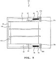
- FIG. 9 is a plan diagram showing a fluorescent X-ray analysis device.
- FIGS. 10 and 11 are cross-sectional diagrams showing a fluorescent X-ray analysis device as viewed from the side.
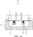
- FIG. 12 is a cross-sectional diagram showing a fluorescent X-ray analysis device as viewed from the front.
- a fluorescent X-ray analysis device 101 is provided with a device main body 50, a housing on the upper side of a sample chamber (door part) 20, an opening/closing mechanism 40 for moving the housing on the upper side of the sample chamber 20, and a computer (not shown) for controlling the entirety of the fluorescent X-ray analysis device 101.
- the device main body 50 has a housing 54 in rectangular parallelepiped form, and an X-ray tube 51 and a detector 52 are installed inside the housing 54.
- an opening 53 in circular form is created in the housing 54 so that the surface of a sample S to be analyzed covers the opening 53 when the sample S is arranged at a predetermined place.
- the X-ray tube 51 has a target, which is an anode, and a filament, which is a cathode, so that primary X-rays generated on the end surface of the target can be emitted.
- the X-ray tube 51 is installed so that the emitted primary X-rays enter through the opening 53. Accordingly, the surface of the sample S to be analyzed is irradiated with primary X-rays when the surface of the sample S to be analyzed covers the opening 53.
- the detector 52 has an X-ray detecting element for detecting the intensity of the fluorescent X-rays .
- the detector 52 is installed so that the fluorescent X-rays generated on the surface of the sample S to be analyzed enter into the detector 52.
- fluorescent X-rays are generated on the surface of the sample S to be analyzed, and the X-ray detecting element detects the intensity of the fluorescent X-rays.
- the opening/closing mechanism 40 is provided with a right side support 41 formed in the right rear portion of the device main body 50 on the upper surface and a left side support 42 formed in the left rear portion of the device main body 50 on the upper surface.
- the housing on the upper side of the sample chamber 20 is provided with a housing 21 in cylindrical form having an upper surface, a right sidewall, a front sidewall, a left sidewall and a rear sidewall.
- an O ring for airtight sealing is attached to the lower surface of the housing 21 so that the housing 21 is placed on the upper surface of the device main body 50 through the O ring so as to form an airtight space between the housing 21 and the device main body 50, in which a sample S is to be arranged.
- the housing on the upper side of the sample chamber 20 needs to have such an intensity as to bear being vacuumed and needs to be made of a material that shields primary X-rays, and therefore is heavy (10 kg, for example).
- a right side pin 22 in cylindrical form is formed so as to protrude to the right from the center portion of the right sidewall of the housing 21 of the housing on the upper side of the sample chamber 20, and thus is attached to the right side connection part 31 that extends in the direction to the front and rear.
- a left side pin 23 in cylindrical form is formed so as to protrude to the left from the center portion of the left sidewall of the housing 21 of the housing on the upper side of the sample chamber 20, and thus is attached to the left side connection part 32 that extends in the front to rear direction.
- a front side connection part 33 that extends in the left to right direction is formed so as to connect one end of the right side connection part 31 to one end of the left side connection part 32.
- a rotational member 31c is formed on the other end of the right side connection part 31 on the upper surface, and the rotational member 31c is attached to the right side support 41 through a rotational axis 31d so as to be rotatable.
- an expandable and contractible spring 43 is attached to the rotational member 31c and the right side support 41 so that a rotational force is applied to hold the right side connection part 31 at a set angle.
- a rotational member 32c is formed on the other end of the left side connection part 32 on the upper surface, and the rotational member 32c is attached to the left side support 42 through a rotational axis 32d so as to be rotatable.
- an expandable and contractible spring 44 is attached to the rotational member 32c and the left side support 42 so that a rotational force is applied to hold the left side connection part 32 at a set angle.
- a user of the fluorescent X-ray analysis device 101 can grasp the front side connection part 33 in order to rotate the housing on the upper side of the sample chamber 20 with the right side connection part 31 and the left side connection part 32 rotating in the forward direction (clockwise) as viewed in the left side diagram of FIGS. 8 and 10 .
- the extending force of the left and right springs 43 and 44 is applied, and therefore, it is not necessary for the user to apply force in order to open or close the housing on the upper side of the sample chamber 20.
- the springs 43 and 44 extend or contract in such a direction that the right side connection part 31 and the left side connection part 32 are held at a set angle.
- the housing on the upper side of the sample chamber 20 can be held in an open position so that the user can place a sample S at a predetermined place or remove the sample S from the predetermined place.
- the user can grasp the front side connection part 33 in order to rotate the housing on the upper side of the sample chamber 20 with the right side connection part 31 and the left side connection part 32 rotating in the backward direction (counter-clockwise) as viewed in the left side diagram of FIGS. 7 and 9 , and then, the housing on the upper side of the sample chamber 20 comes to a closed position.
- the X-ray tube 51 emits primary X-rays, and therefore, a left side lock switch 170 and a right side lock switch 180 are provided in order to prevent the user from opening the housing on the upper side of the sample chamber 20 by mistake during the measurement process (see FIG. 12 ) .
- the left side lock switch 170 is provided with a left side actuator insertion part 71 and a left side actuator 172.
- the left side actuator 172 has a rod 172a made of a metal and is provided on the left of the front sidewall of the housing on the upper side of the sample chamber 20. In addition, the rod 172a protrudes towards the bottom by a predetermined distance from the lower surface of the front sidewall.
- the left side actuator insertion part 71 has a housing 71a in rectangular parallelepiped form and is provided in the upper left portion of the front sidewall of the device main body 50. An insertion hole is created through the upper surface of the housing 71a, and a switch (not shown) is provided inside the housing 71a.
- the rod 172a is inserted through the insertion hole when the housing on the upper side of the sample chamber 20 comes to the closed position so that the switch is electrically connected so as to output a signal to the computer. Consequently, the computer makes it impossible for the housing on the upper side of the sample chamber 20 to move to the open position. Meanwhile, the rod 172a is pulled out of the insertion hole when the housing on the upper side of the sample chamber 20 comes to the open position so that the switch is electrically disconnected so as to not output a signal to the computer.
- the left side lock switch 180 has the same structure as the right side lock switch 170.
- Patent Literature 1 Utility Model Registration No. 3187413
- a user of the fluorescent X-ray analysis device 101 arranges a sample S at a predetermined place or removes the sample S from the predetermined place after holding the housing on the upper side of the sample chamber 20 in the open position. At this time, the user's hand or the sample S may hit the rod 172a, which may damage the rod 172a.
- an object of the present invention is to provide an analysis device where the actuators can be accommodated in order to prevent them from being an obstacle to the user or to prevent them from being damaged when the housing on the upper side of the sample chamber is opened.
- the present invention provides an analysis device with: a device main body in which a sample is to be arranged; a door part that is movable between an open position for opening the device main body and a closed position for closing the device main body; and a lock switch having an actuator insertion part that is provided in the device main body and an actuator that is provided in the door part, wherein it becomes impossible for the door part to move to the open position when the actuator is inserted into the actuator insertion part, characterized in that the actuator is movable between a protruding position where the actuator protrudes from the door part and an accommodated position where the actuator is accommodated in the door part, and the actuator is placed in the protruding position when the door part is in the closed position, whereas the actuator is placed in the accommodated position when the door part is in the open position.
- the actuators are accommodated (not protruding), which do not hamper the user's work and prevent the actuators from being damaged when the door part is opened, and thus, operability and safety are increased.
- the appearance is better, which gives an impression of safety.
- the analysis device may further include a wire rope in such a manner that an end of the actuator is attached to one end of the wire rope, and a link mechanism that slides as the door part moves is attached to the other end of the wire rope.
- a compressed spring that applies a force so that the actuator moves to the protruding position may be attached to the actuator in the analysis device according to the present invention.
- the door part may have an upper surface, a right sidewall, a front sidewall, a left sidewall, a rear sidewall, a right side connection part that is attached to the right sidewall and a left side connection part that is attached to the left sidewall so as to be rotatable between an open position and a closed position with one end of the right side connection part and one end of the left side connection part as a rotational axis in the analysis device according to the present invention.
- an X-ray tube and a detector may be installed inside the device main body in the analysis device according to the present invention.
- FIGS. 1 and 2 are side diagrams schematically showing an example of the structure of the fluorescent X-ray analysis device according to an embodiment of the present invention.
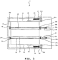
- FIG. 3 is a plan diagram showing the fluorescent X-ray analysis device.
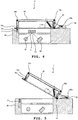
- FIGS. 4 and 5 are cross-sectional diagrams showing the fluorescent X-ray analysis device from the side.
- FIG. 6 is a cross-sectional diagram showing the fluorescent X-ray analysis device from the front.
- the same symbols are attached to the same components as in the fluorescent X-ray analysis device 101.
- the fluorescent X-ray analysis device 1 is provided with a device main body 50, a housing on the upper side of a sample chamber (door part) 20, an opening/closing mechanism 40 for moving the housing on the upper side of the sample chamber 20, two lock switches 70 and 80, and a computer (not shown) for controlling the entirety of the fluorescent X-ray analysis device 1.
- the device main body 50 has a housing 54 in rectangular parallelepiped form, and an X-ray tube 51 and a detector 52 are installed inside the housing 54.
- a circular opening 53 is created in a wall of the housing 54, and a sample S can be mounted in a predetermined place so that the surface of the sample S to be analyzed covers the opening 53.
- a left side slide rail 56 and a left side pulley 57 with a first cover are formed in order to move a plate 55 in the front to rear directions.
- left side pins 55a and 55b in columnar form are formed so as to protrude to the left.
- a right side slide rail 58 and a right side pulley with the first cover are formed in order to move a plate 59 in the front to rear directions.
- right side pins 59a and 59b in columnar form are formed so as to protrude to the right.
- the housing on the upper side of the sample chamber 20 is provided with a cylindrical housing portion 21 having an upper surface, a right sidewall, a front sidewall, a left sidewall and a rear sidewall.
- an O-ring for airtight sealing is attached to the lower surface of the housing portion 21, and the housing portion 21 and the device main body 50 form an airtight space within which a sample S is to be arranged when the housing portion 21 is mounted on the upper surface of the device main body 50 with the O-ring in-between.
- a left side plate 24 is formed so as to protrude.
- a left side pin 24a in columnar form that protrudes to the left and a left side pulley 24b with a second cover are formed.
- a left side pulley 24c with a third cover is formed.
- a right side plate 25 is formed so as to protrude.
- a right side pin in columnar form that protrudes to the right and a right side pulley 25b with a second cover are formed.
- a right side pulley 25c with a third cover is formed.
- a first opening is created at a first end of a left side linking member 91, and a second opening is created at a second end that is away from the first end by a predetermined distance.
- the left side pin 24a is inserted into the first opening, and the left side pin 55a is inserted into the second opening.
- the plate 55 automatically moves to the rear within the left side slide rail 56 when the housing on the upper side of the sample chamber 20 is opened. Meanwhile, the plate 55 automatically moves to the front within the left side slide rail 56 when the housing on the upper side of the sample chamber 20 is closed.
- a left side lock switch 70 is provided with a left side actuator insertion part 71 and a left side actuator 72.
- the left side actuator 72 has a rod 72a made of a metal, a cylindrical slide bearing 72c for moving the rod 72a in the upward and downward directions, and a compressed spring 72b arranged within the slide bearing 72c, and is provided in the left portion of the front sidewall of the housing on the upper side of the sample chamber 20.
- the rod 72a is movable between the protruding position where the rod 72a protrudes downward from the lower surface of the front sidewall by a predetermined distance (lower position within the slide bearing 72c) and the accommodated position where the rod 72a is accommodated within the housing on the upper side of the sample chamber 20 (upper position within the slide bearing 72c).
- the compressed spring 72b applies a force so that the rod 72a moves to the protruding position.
- a first end of a left side wire rope 92 is attached to an end of the rod 72a and passes through the space between the pulley and the cover (wire guard for preventing the wire from being disengaged) of the left side pulley 24c with the third cover, the space between the pulley and the cover (wire guard for preventing the wire from being disengaged) of the left side pulley 24b with the second cover, and the space between the pulley and the cover (wire guard for preventing the wire from being disengaged) of the left side pulley 57 with the first cover.
- a second end of the left side wire rope 92 that is away from the first end by a predetermined distance is attached to the left side pin 55b on the plate 55.
- the rod 72a automatically moves upward within the slide bearing 72c when the plate 55 moves to the rear within the left side slide rail 56. Meanwhile, the rod 72a automatically moves downward within the slide bearing 72c when the plate 55 moves to the front within the left side slide rail 56.
- the right side lock switch 80 has the same configuration as the left side lock switch 70.
- the user grasps the front side connection part 33 and rotates the right side connection part 31 and the left side connection part 32 in the forward direction (clockwise) as viewed in the left side diagrams in FIGS. 2 and 4 in order to rotate the housing on the upper side of the sample chamber 20.
- the plate 55 automatically moves to the rear within the left side slide rail 56, and the rod 72a automatically moves upward within the slide bearing 72c. That is to say, the rod 72a is automatically placed in the accommodated position.
- the user can place a sample S in a predetermined place or can remove the sample S from the predetermined place without the rod 72a being an obstacle or without damaging the rod 72a.
- the user grasps the front side connection part 33 and rotates the right side connection part 31 and the left side connection part 32 in the backward direction (counterclockwise) as viewed in the left side diagram in FIGS. 1 and 3 in order to rotate the housing on the upper side of the sample chamber 20 to the closed position.
- the plate 55 automatically moves to the front within the left side slide rail 56, and the rod 72a automatically moves downward within the slide bearing 72c. That is to say, the rod 72a is automatically placed in the protruding position, and thus, the rod 72a is inserted into the insertion hole.
- a switch is turned on for electrical connection so as to output a signal to the computer, and the computer makes it impossible for the housing on the upper side of the sample chamber 20 to move to the open position.
- the present invention can be applied in the same manner to analysis devices where it is necessary to open or close the sample chamber when a sample to be analyzed is installed in the sample chamber (or measurement place).
- the present invention can be applied to fluorescent X-ray analysis devices for acquiring information on an element that is included in a sample.
Landscapes
- Physics & Mathematics (AREA)
- Health & Medical Sciences (AREA)
- Life Sciences & Earth Sciences (AREA)
- Chemical & Material Sciences (AREA)
- Analytical Chemistry (AREA)
- Biochemistry (AREA)
- General Health & Medical Sciences (AREA)
- General Physics & Mathematics (AREA)
- Immunology (AREA)
- Pathology (AREA)
- Analysing Materials By The Use Of Radiation (AREA)
Abstract
Description
- The present invention relates to an analysis device, and in particular to a fluorescent X-ray analysis device for acquiring information on an element included in a sample.
- Fluorescent X-ray analysis devices are used for qualitative or quantitative analysis of an element that is included in a solid sample, a powder sample or a liquid sample by detecting fluorescent X-rays that are emitted from the sample, which is irradiated with primary X-rays for excitation (see Patent Document 1).
-
FIGS. 7 and 8 are side diagrams schematically showing the configuration of a conventional fluorescent X-ray analysis device.FIG. 9 is a plan diagram showing a fluorescent X-ray analysis device.FIGS. 10 and 11 are cross-sectional diagrams showing a fluorescent X-ray analysis device as viewed from the side.FIG. 12 is a cross-sectional diagram showing a fluorescent X-ray analysis device as viewed from the front. A fluorescentX-ray analysis device 101 is provided with a devicemain body 50, a housing on the upper side of a sample chamber (door part) 20, an opening/closing mechanism 40 for moving the housing on the upper side of thesample chamber 20, and a computer (not shown) for controlling the entirety of the fluorescentX-ray analysis device 101. - The device
main body 50 has ahousing 54 in rectangular parallelepiped form, and anX-ray tube 51 and adetector 52 are installed inside thehousing 54. In addition, anopening 53 in circular form is created in thehousing 54 so that the surface of a sample S to be analyzed covers theopening 53 when the sample S is arranged at a predetermined place. - The
X-ray tube 51 has a target, which is an anode, and a filament, which is a cathode, so that primary X-rays generated on the end surface of the target can be emitted. TheX-ray tube 51 is installed so that the emitted primary X-rays enter through theopening 53. Accordingly, the surface of the sample S to be analyzed is irradiated with primary X-rays when the surface of the sample S to be analyzed covers theopening 53. - The
detector 52 has an X-ray detecting element for detecting the intensity of the fluorescent X-rays . Thedetector 52 is installed so that the fluorescent X-rays generated on the surface of the sample S to be analyzed enter into thedetector 52. When the surface of the sample S to be analyzed is irradiated with primary X-rays, fluorescent X-rays are generated on the surface of the sample S to be analyzed, and the X-ray detecting element detects the intensity of the fluorescent X-rays. - The opening/
closing mechanism 40 is provided with aright side support 41 formed in the right rear portion of the devicemain body 50 on the upper surface and aleft side support 42 formed in the left rear portion of the devicemain body 50 on the upper surface. - The housing on the upper side of the
sample chamber 20 is provided with ahousing 21 in cylindrical form having an upper surface, a right sidewall, a front sidewall, a left sidewall and a rear sidewall. In addition, an O ring for airtight sealing is attached to the lower surface of thehousing 21 so that thehousing 21 is placed on the upper surface of the devicemain body 50 through the O ring so as to form an airtight space between thehousing 21 and the devicemain body 50, in which a sample S is to be arranged. Here, the housing on the upper side of thesample chamber 20 needs to have such an intensity as to bear being vacuumed and needs to be made of a material that shields primary X-rays, and therefore is heavy (10 kg, for example). - A
right side pin 22 in cylindrical form is formed so as to protrude to the right from the center portion of the right sidewall of thehousing 21 of the housing on the upper side of thesample chamber 20, and thus is attached to the rightside connection part 31 that extends in the direction to the front and rear. In addition, aleft side pin 23 in cylindrical form is formed so as to protrude to the left from the center portion of the left sidewall of thehousing 21 of the housing on the upper side of thesample chamber 20, and thus is attached to the leftside connection part 32 that extends in the front to rear direction. Furthermore, a frontside connection part 33 that extends in the left to right direction is formed so as to connect one end of the rightside connection part 31 to one end of the leftside connection part 32. - A
rotational member 31c is formed on the other end of the rightside connection part 31 on the upper surface, and therotational member 31c is attached to theright side support 41 through arotational axis 31d so as to be rotatable. In addition, an expandable andcontractible spring 43 is attached to therotational member 31c and theright side support 41 so that a rotational force is applied to hold the rightside connection part 31 at a set angle. - A
rotational member 32c is formed on the other end of the leftside connection part 32 on the upper surface, and therotational member 32c is attached to theleft side support 42 through arotational axis 32d so as to be rotatable. In addition, an expandable andcontractible spring 44 is attached to therotational member 32c and theleft side support 42 so that a rotational force is applied to hold the leftside connection part 32 at a set angle. - A user of the fluorescent
X-ray analysis device 101 can grasp the frontside connection part 33 in order to rotate the housing on the upper side of thesample chamber 20 with the rightside connection part 31 and the leftside connection part 32 rotating in the forward direction (clockwise) as viewed in the left side diagram ofFIGS. 8 and10 . At this time, the extending force of the left andright springs sample chamber 20. In addition, thesprings side connection part 31 and the leftside connection part 32 are held at a set angle. As a result, the housing on the upper side of thesample chamber 20 can be held in an open position so that the user can place a sample S at a predetermined place or remove the sample S from the predetermined place. - After that, the user can grasp the front
side connection part 33 in order to rotate the housing on the upper side of thesample chamber 20 with the rightside connection part 31 and the leftside connection part 32 rotating in the backward direction (counter-clockwise) as viewed in the left side diagram ofFIGS. 7 and9 , and then, the housing on the upper side of thesample chamber 20 comes to a closed position. - In the fluorescent
X-ray analysis device 101, theX-ray tube 51 emits primary X-rays, and therefore, a leftside lock switch 170 and a rightside lock switch 180 are provided in order to prevent the user from opening the housing on the upper side of thesample chamber 20 by mistake during the measurement process (seeFIG. 12 ) . - The left
side lock switch 170 is provided with a left sideactuator insertion part 71 and a left side actuator 172. The left side actuator 172 has arod 172a made of a metal and is provided on the left of the front sidewall of the housing on the upper side of thesample chamber 20. In addition, therod 172a protrudes towards the bottom by a predetermined distance from the lower surface of the front sidewall. The left sideactuator insertion part 71 has ahousing 71a in rectangular parallelepiped form and is provided in the upper left portion of the front sidewall of the devicemain body 50. An insertion hole is created through the upper surface of thehousing 71a, and a switch (not shown) is provided inside thehousing 71a. - As a result, the
rod 172a is inserted through the insertion hole when the housing on the upper side of thesample chamber 20 comes to the closed position so that the switch is electrically connected so as to output a signal to the computer. Consequently, the computer makes it impossible for the housing on the upper side of thesample chamber 20 to move to the open position. Meanwhile, therod 172a is pulled out of the insertion hole when the housing on the upper side of thesample chamber 20 comes to the open position so that the switch is electrically disconnected so as to not output a signal to the computer. - Here, the left
side lock switch 180 has the same structure as the rightside lock switch 170. - Patent Literature 1: Utility Model Registration No.
3187413 - As described above, a user of the fluorescent
X-ray analysis device 101 arranges a sample S at a predetermined place or removes the sample S from the predetermined place after holding the housing on the upper side of thesample chamber 20 in the open position. At this time, the user's hand or the sample S may hit therod 172a, which may damage therod 172a. - Therefore, an object of the present invention is to provide an analysis device where the actuators can be accommodated in order to prevent them from being an obstacle to the user or to prevent them from being damaged when the housing on the upper side of the sample chamber is opened.
- In order to achieve the above-described object, the present invention provides an analysis device with: a device main body in which a sample is to be arranged; a door part that is movable between an open position for opening the device main body and a closed position for closing the device main body; and a lock switch having an actuator insertion part that is provided in the device main body and an actuator that is provided in the door part, wherein it becomes impossible for the door part to move to the open position when the actuator is inserted into the actuator insertion part, characterized in that the actuator is movable between a protruding position where the actuator protrudes from the door part and an accommodated position where the actuator is accommodated in the door part, and the actuator is placed in the protruding position when the door part is in the closed position, whereas the actuator is placed in the accommodated position when the door part is in the open position.
- As described above, in the analysis device according to the present invention, the actuators are accommodated (not protruding), which do not hamper the user's work and prevent the actuators from being damaged when the door part is opened, and thus, operability and safety are increased. In addition, the appearance is better, which gives an impression of safety.
- The analysis device according to the present invention may further include a wire rope in such a manner that an end of the actuator is attached to one end of the wire rope, and a link mechanism that slides as the door part moves is attached to the other end of the wire rope.
- In addition, a compressed spring that applies a force so that the actuator moves to the protruding position may be attached to the actuator in the analysis device according to the present invention.
- Furthermore, the door part may have an upper surface, a right sidewall, a front sidewall, a left sidewall, a rear sidewall, a right side connection part that is attached to the right sidewall and a left side connection part that is attached to the left sidewall so as to be rotatable between an open position and a closed position with one end of the right side connection part and one end of the left side connection part as a rotational axis in the analysis device according to the present invention.
- Moreover, an X-ray tube and a detector may be installed inside the device main body in the analysis device according to the present invention.
-
-
FIG. 1 is a side diagram schematically showing an example of the structure of the fluorescent X-ray analysis device according to an embodiment of the present invention; -
FIG. 2 is a side diagram schematically showing an example of the structure of the fluorescent X-ray analysis device according to the embodiment of the present example; -
FIG. 3 is a plan diagram showing a fluorescent X-ray analysis device; -
FIG. 4 is a cross-sectional diagram showing the fluorescent X-ray analysis device; -
FIG. 5 is a cross-sectional diagram showing the fluorescent X-ray analysis device; -
FIG. 6 is a cross-sectional diagram showing the fluorescent X-ray analysis device; -
FIG. 7 is a side diagram schematically showing the structure of a conventional fluorescent X-ray analysis device; -
FIG. 8 is a side diagram schematically showing the structure of the conventional fluorescent X-ray analysis device; -
FIG. 9 is a plan diagram showing a fluorescent X-ray analysis device; -
FIG. 10 is a cross-sectional diagram showing the fluorescent X-ray analysis device; -
FIG. 11 is a cross-sectional diagram showing the fluorescent X-ray analysis device; and -
FIG. 12 is a cross-sectional diagram showing the fluorescent X-ray analysis device. - In the following, an embodiment of the present invention is described in reference to the drawings. Here, the present invention is not limited to the below-described embodiment, but needless to say, various modifications are included as long as the gist of the present invention is not deviated from.
-
FIGS. 1 and 2 are side diagrams schematically showing an example of the structure of the fluorescent X-ray analysis device according to an embodiment of the present invention.FIG. 3 is a plan diagram showing the fluorescent X-ray analysis device.FIGS. 4 and 5 are cross-sectional diagrams showing the fluorescent X-ray analysis device from the side.FIG. 6 is a cross-sectional diagram showing the fluorescent X-ray analysis device from the front. Here, the same symbols are attached to the same components as in the fluorescentX-ray analysis device 101. - The fluorescent
X-ray analysis device 1 is provided with a devicemain body 50, a housing on the upper side of a sample chamber (door part) 20, an opening/closing mechanism 40 for moving the housing on the upper side of thesample chamber 20, twolock switches X-ray analysis device 1. - The device
main body 50 has ahousing 54 in rectangular parallelepiped form, and anX-ray tube 51 and adetector 52 are installed inside thehousing 54. In addition, acircular opening 53 is created in a wall of thehousing 54, and a sample S can be mounted in a predetermined place so that the surface of the sample S to be analyzed covers theopening 53. - In the rear left portion on the upper surface of the
housing 54, a leftside slide rail 56 and aleft side pulley 57 with a first cover are formed in order to move aplate 55 in the front to rear directions. In theplate 55, left side pins 55a and 55b in columnar form are formed so as to protrude to the left. In the rear right portion on the upper surface of thehousing 54, a rightside slide rail 58 and a right side pulley with the first cover are formed in order to move a plate 59 in the front to rear directions. In the plate 59, right side pins 59a and 59b in columnar form are formed so as to protrude to the right. - The housing on the upper side of the
sample chamber 20 is provided with acylindrical housing portion 21 having an upper surface, a right sidewall, a front sidewall, a left sidewall and a rear sidewall. In addition, an O-ring for airtight sealing is attached to the lower surface of thehousing portion 21, and thehousing portion 21 and the devicemain body 50 form an airtight space within which a sample S is to be arranged when thehousing portion 21 is mounted on the upper surface of the devicemain body 50 with the O-ring in-between. - In the left portion of the outer surface of the
housing portion 21 in the housing on the upper side of thesample chamber 20, aleft side plate 24 is formed so as to protrude. At one end of theleft side plate 24, aleft side pin 24a in columnar form that protrudes to the left and aleft side pulley 24b with a second cover are formed. At the other end of theleft side plate 24, aleft side pulley 24c with a third cover is formed. - In the right portion of the outer surface of the
housing portion 21 in the housing on the upper side of thesample chamber 20, aright side plate 25 is formed so as to protrude. At one end of theright side plate 25, a right side pin in columnar form that protrudes to the right and aright side pulley 25b with a second cover are formed. At the other end of theright side plate 25, aright side pulley 25c with a third cover is formed. - A first opening is created at a first end of a left
side linking member 91, and a second opening is created at a second end that is away from the first end by a predetermined distance. Theleft side pin 24a is inserted into the first opening, and theleft side pin 55a is inserted into the second opening. As a result, theplate 55 automatically moves to the rear within the leftside slide rail 56 when the housing on the upper side of thesample chamber 20 is opened. Meanwhile, theplate 55 automatically moves to the front within the leftside slide rail 56 when the housing on the upper side of thesample chamber 20 is closed. - A left
side lock switch 70 is provided with a left sideactuator insertion part 71 and a left side actuator 72. The left side actuator 72 has arod 72a made of a metal, acylindrical slide bearing 72c for moving therod 72a in the upward and downward directions, and acompressed spring 72b arranged within theslide bearing 72c, and is provided in the left portion of the front sidewall of the housing on the upper side of thesample chamber 20. In addition, therod 72a is movable between the protruding position where therod 72a protrudes downward from the lower surface of the front sidewall by a predetermined distance (lower position within theslide bearing 72c) and the accommodated position where therod 72a is accommodated within the housing on the upper side of the sample chamber 20 (upper position within theslide bearing 72c). Thecompressed spring 72b applies a force so that therod 72a moves to the protruding position. - A first end of a left
side wire rope 92 is attached to an end of therod 72a and passes through the space between the pulley and the cover (wire guard for preventing the wire from being disengaged) of theleft side pulley 24c with the third cover, the space between the pulley and the cover (wire guard for preventing the wire from being disengaged) of theleft side pulley 24b with the second cover, and the space between the pulley and the cover (wire guard for preventing the wire from being disengaged) of theleft side pulley 57 with the first cover. A second end of the leftside wire rope 92 that is away from the first end by a predetermined distance is attached to theleft side pin 55b on theplate 55. As a result, therod 72a automatically moves upward within theslide bearing 72c when theplate 55 moves to the rear within the leftside slide rail 56. Meanwhile, therod 72a automatically moves downward within theslide bearing 72c when theplate 55 moves to the front within the leftside slide rail 56. - Here, the right
side lock switch 80 has the same configuration as the leftside lock switch 70. - In the fluorescent
X-ray analysis device 1 having such a configuration, the user grasps the frontside connection part 33 and rotates the rightside connection part 31 and the leftside connection part 32 in the forward direction (clockwise) as viewed in the left side diagrams inFIGS. 2 and4 in order to rotate the housing on the upper side of thesample chamber 20. At this time, theplate 55 automatically moves to the rear within the leftside slide rail 56, and therod 72a automatically moves upward within theslide bearing 72c. That is to say, therod 72a is automatically placed in the accommodated position. As a result, the user can place a sample S in a predetermined place or can remove the sample S from the predetermined place without therod 72a being an obstacle or without damaging therod 72a. - After that, the user grasps the front
side connection part 33 and rotates the rightside connection part 31 and the leftside connection part 32 in the backward direction (counterclockwise) as viewed in the left side diagram inFIGS. 1 and3 in order to rotate the housing on the upper side of thesample chamber 20 to the closed position. At this time, theplate 55 automatically moves to the front within the leftside slide rail 56, and therod 72a automatically moves downward within theslide bearing 72c. That is to say, therod 72a is automatically placed in the protruding position, and thus, therod 72a is inserted into the insertion hole. As a result, a switch is turned on for electrical connection so as to output a signal to the computer, and the computer makes it impossible for the housing on the upper side of thesample chamber 20 to move to the open position. - Though an embodiment is described by citing the fluorescent
X-ray analysis device 1 as an example, the present invention can be applied in the same manner to analysis devices where it is necessary to open or close the sample chamber when a sample to be analyzed is installed in the sample chamber (or measurement place). - The present invention can be applied to fluorescent X-ray analysis devices for acquiring information on an element that is included in a sample.
-
- 1
- fluorescent X-ray analysis device
- 20
- housing on the upper side of a sample chamber (door part)
- 50
- device main body
- 70
- lock switch
- 71
- actuator insertion part
- 72
- actuator
Claims (5)
- An analysis device, comprising:a device main body in which a sample is to be arranged;a door part that is movable between an open position for opening the device main body and a closed position for closing the device main body; anda lock switch having an actuator insertion part that is provided in the device main body and an actuator that is provided in the door part, whereinit becomes impossible for the door part to move to the open position when the actuator is inserted into the actuator insertion part, characterized in thatthe actuator is movable between a protruding position where the actuator protrudes from the door part and an accommodated position where the actuator is accommodated in the door part, andthe actuator is placed in the protruding position when the door part is in the closed position, whereas the actuator is placed in the accommodated position when the door part is in the open position.
- The analysis device according to claim 1, characterized in thatthe analysis device further comprises a wire rope,an end of the actuator is attached to one end of the wire rope, anda link mechanism that slides as the door part moves is attached to the other end of the wire rope.
- The analysis device according to claim 1 or 2, characterized in that a compressed spring that applies a force so that the actuator moves to the protruding position is attached to the actuator.
- The analysis device according to any of claims 1 through 3, characterized in thatthe door part comprises an upper surface, a right sidewall, a front sidewall, a left sidewall and a rear sidewall,the door part has a right side connection part that is attached to the right sidewall and a left side connection part that is attached to the left sidewall, andthe door is rotatable between an open position and a closed position with one end of the right side connection part and one end of the left side connection part as a rotational axis.
- The analysis device according to any of claims 1 through 4, characterized in that an X-ray tube and a detector are installed inside the device main body.
Applications Claiming Priority (1)
| Application Number | Priority Date | Filing Date | Title |
|---|---|---|---|
| PCT/JP2015/077417 WO2017056174A1 (en) | 2015-09-29 | 2015-09-29 | Analysis device |
Publications (3)
| Publication Number | Publication Date |
|---|---|
| EP3358342A1 true EP3358342A1 (en) | 2018-08-08 |
| EP3358342A4 EP3358342A4 (en) | 2019-05-29 |
| EP3358342B1 EP3358342B1 (en) | 2023-08-09 |
Family
ID=58423034
Family Applications (1)
| Application Number | Title | Priority Date | Filing Date |
|---|---|---|---|
| EP15905329.7A Active EP3358342B1 (en) | 2015-09-29 | 2015-09-29 | Xrf analysis device |
Country Status (3)
| Country | Link |
|---|---|
| EP (1) | EP3358342B1 (en) |
| JP (1) | JP6493544B2 (en) |
| WO (1) | WO2017056174A1 (en) |
Families Citing this family (2)
| Publication number | Priority date | Publication date | Assignee | Title |
|---|---|---|---|---|
| JP7605021B2 (en) | 2021-05-27 | 2024-12-24 | 株式会社島津製作所 | X-ray analysis equipment |
| CN117110207B (en) * | 2023-06-27 | 2024-09-10 | 安徽通利预应力科技有限公司 | Online elemental analysis device for steel strand production |
Family Cites Families (9)
| Publication number | Priority date | Publication date | Assignee | Title |
|---|---|---|---|---|
| US3018127A (en) * | 1958-10-30 | 1962-01-23 | Westinghouse Electric Corp | Enclosed device with cover-mounting means |
| US3465803A (en) * | 1967-07-26 | 1969-09-09 | Penn Eng & Mfg Corp | Captive screw device and a method for securing together the parts thereof |
| US5059075A (en) * | 1989-03-31 | 1991-10-22 | Cooper Industries, Inc. | Retracting screw assembly |
| JP2000162161A (en) * | 1998-11-26 | 2000-06-16 | Shimadzu Corp | X-ray fluorescence analyzer |
| JP5009684B2 (en) * | 2006-06-30 | 2012-08-22 | シスメックス株式会社 | Sample analyzer |
| JP5509604B2 (en) * | 2009-02-02 | 2014-06-04 | 株式会社島津製作所 | X-ray analyzer |
| JP5838623B2 (en) * | 2011-07-06 | 2016-01-06 | 沖電気工業株式会社 | Locking device |
| JP5907375B2 (en) * | 2011-12-28 | 2016-04-26 | 株式会社テクノエックス | X-ray fluorescence analyzer and X-ray fluorescence analysis method |
| JP3187413U (en) * | 2013-07-19 | 2013-11-28 | 株式会社島津製作所 | X-ray fluorescence analyzer |
-
2015
- 2015-09-29 JP JP2017542545A patent/JP6493544B2/en active Active
- 2015-09-29 WO PCT/JP2015/077417 patent/WO2017056174A1/en not_active Ceased
- 2015-09-29 EP EP15905329.7A patent/EP3358342B1/en active Active
Also Published As
| Publication number | Publication date |
|---|---|
| EP3358342B1 (en) | 2023-08-09 |
| JP6493544B2 (en) | 2019-04-03 |
| JPWO2017056174A1 (en) | 2018-05-31 |
| EP3358342A4 (en) | 2019-05-29 |
| WO2017056174A1 (en) | 2017-04-06 |
Similar Documents
| Publication | Publication Date | Title |
|---|---|---|
| JP6130843B2 (en) | A high safety control mechanism for a device for hermetic transfer between two enclosed spaces. | |
| US10916386B2 (en) | Handle assembly with defeater and related methods | |
| EP3037825B1 (en) | Automatic analyzer | |
| CN105675640B (en) | Fluorescent X-ray analyzer | |
| EP3358342A1 (en) | Analysis device | |
| US20180337469A1 (en) | Terminal detachable device | |
| KR102422687B1 (en) | Method and apparatus for demolding and analyzing a direct analysis sample | |
| CN110261364B (en) | Handheld Raman spectrometer and detection method | |
| JP5948371B2 (en) | Electric padlock | |
| JP3187413U (en) | X-ray fluorescence analyzer | |
| JP5863859B2 (en) | X-ray equipment | |
| NL2020694B1 (en) | Analysis equipment with wireless connection | |
| KR102390721B1 (en) | X-ray inspection device | |
| JP5240258B2 (en) | X-ray analyzer | |
| US10651635B2 (en) | Panel for accommodating a draw-out device | |
| JP3138602U (en) | X-ray analyzer | |
| JP6221719B2 (en) | Light measuring device and safety device used therefor | |
| CN202930366U (en) | Wafer cassette base | |
| KR20160051710A (en) | X-ray Tube Module Having Improved Shielding Capability and Method Using the Same | |
| JP4111336B2 (en) | Device for inspecting samples with X-rays | |
| JP2016050827A (en) | Radiation analyzer | |
| JP3195191U (en) | Security device | |
| US10060160B2 (en) | Latch assembly | |
| EP2058710A3 (en) | Developing unit | |
| JP6058098B2 (en) | X-ray equipment |
Legal Events
| Date | Code | Title | Description |
|---|---|---|---|
| STAA | Information on the status of an ep patent application or granted ep patent |
Free format text: STATUS: THE INTERNATIONAL PUBLICATION HAS BEEN MADE |
|
| PUAI | Public reference made under article 153(3) epc to a published international application that has entered the european phase |
Free format text: ORIGINAL CODE: 0009012 |
|
| STAA | Information on the status of an ep patent application or granted ep patent |
Free format text: STATUS: REQUEST FOR EXAMINATION WAS MADE |
|
| 17P | Request for examination filed |
Effective date: 20180319 |
|
| AK | Designated contracting states |
Kind code of ref document: A1 Designated state(s): AL AT BE BG CH CY CZ DE DK EE ES FI FR GB GR HR HU IE IS IT LI LT LU LV MC MK MT NL NO PL PT RO RS SE SI SK SM TR |
|
| AX | Request for extension of the european patent |
Extension state: BA ME |
|
| DAV | Request for validation of the european patent (deleted) | ||
| DAX | Request for extension of the european patent (deleted) | ||
| A4 | Supplementary search report drawn up and despatched |
Effective date: 20190502 |
|
| RIC1 | Information provided on ipc code assigned before grant |
Ipc: G01N 23/223 20060101AFI20190425BHEP Ipc: E05B 63/18 20060101ALI20190425BHEP Ipc: B65D 43/16 20060101ALI20190425BHEP |
|
| STAA | Information on the status of an ep patent application or granted ep patent |
Free format text: STATUS: EXAMINATION IS IN PROGRESS |
|
| 17Q | First examination report despatched |
Effective date: 20201120 |
|
| GRAP | Despatch of communication of intention to grant a patent |
Free format text: ORIGINAL CODE: EPIDOSNIGR1 |
|
| STAA | Information on the status of an ep patent application or granted ep patent |
Free format text: STATUS: GRANT OF PATENT IS INTENDED |
|
| RIC1 | Information provided on ipc code assigned before grant |
Ipc: E05B 47/00 20060101ALN20230303BHEP Ipc: E05B 53/00 20060101ALI20230303BHEP Ipc: G01N 23/223 20060101AFI20230303BHEP |
|
| RIC1 | Information provided on ipc code assigned before grant |
Ipc: E05B 47/00 20060101ALN20230313BHEP Ipc: E05B 53/00 20060101ALI20230313BHEP Ipc: G01N 23/223 20060101AFI20230313BHEP |
|
| INTG | Intention to grant announced |
Effective date: 20230404 |
|
| GRAS | Grant fee paid |
Free format text: ORIGINAL CODE: EPIDOSNIGR3 |
|
| GRAA | (expected) grant |
Free format text: ORIGINAL CODE: 0009210 |
|
| STAA | Information on the status of an ep patent application or granted ep patent |
Free format text: STATUS: THE PATENT HAS BEEN GRANTED |
|
| AK | Designated contracting states |
Kind code of ref document: B1 Designated state(s): AL AT BE BG CH CY CZ DE DK EE ES FI FR GB GR HR HU IE IS IT LI LT LU LV MC MK MT NL NO PL PT RO RS SE SI SK SM TR |
|
| REG | Reference to a national code |
Ref country code: GB Ref legal event code: FG4D |
|
| REG | Reference to a national code |
Ref country code: CH Ref legal event code: EP |
|
| REG | Reference to a national code |
Ref country code: IE Ref legal event code: FG4D |
|
| REG | Reference to a national code |
Ref country code: DE Ref legal event code: R096 Ref document number: 602015085095 Country of ref document: DE |
|
| REG | Reference to a national code |
Ref country code: LT Ref legal event code: MG9D |
|
| REG | Reference to a national code |
Ref country code: NL Ref legal event code: MP Effective date: 20230809 |
|
| REG | Reference to a national code |
Ref country code: AT Ref legal event code: MK05 Ref document number: 1598094 Country of ref document: AT Kind code of ref document: T Effective date: 20230809 |
|
| PG25 | Lapsed in a contracting state [announced via postgrant information from national office to epo] |
Ref country code: GR Free format text: LAPSE BECAUSE OF FAILURE TO SUBMIT A TRANSLATION OF THE DESCRIPTION OR TO PAY THE FEE WITHIN THE PRESCRIBED TIME-LIMIT Effective date: 20231110 |
|
| PG25 | Lapsed in a contracting state [announced via postgrant information from national office to epo] |
Ref country code: IS Free format text: LAPSE BECAUSE OF FAILURE TO SUBMIT A TRANSLATION OF THE DESCRIPTION OR TO PAY THE FEE WITHIN THE PRESCRIBED TIME-LIMIT Effective date: 20231209 |
|
| PG25 | Lapsed in a contracting state [announced via postgrant information from national office to epo] |
Ref country code: SE Free format text: LAPSE BECAUSE OF FAILURE TO SUBMIT A TRANSLATION OF THE DESCRIPTION OR TO PAY THE FEE WITHIN THE PRESCRIBED TIME-LIMIT Effective date: 20230809 Ref country code: RS Free format text: LAPSE BECAUSE OF FAILURE TO SUBMIT A TRANSLATION OF THE DESCRIPTION OR TO PAY THE FEE WITHIN THE PRESCRIBED TIME-LIMIT Effective date: 20230809 Ref country code: PT Free format text: LAPSE BECAUSE OF FAILURE TO SUBMIT A TRANSLATION OF THE DESCRIPTION OR TO PAY THE FEE WITHIN THE PRESCRIBED TIME-LIMIT Effective date: 20231211 Ref country code: NO Free format text: LAPSE BECAUSE OF FAILURE TO SUBMIT A TRANSLATION OF THE DESCRIPTION OR TO PAY THE FEE WITHIN THE PRESCRIBED TIME-LIMIT Effective date: 20231109 Ref country code: NL Free format text: LAPSE BECAUSE OF FAILURE TO SUBMIT A TRANSLATION OF THE DESCRIPTION OR TO PAY THE FEE WITHIN THE PRESCRIBED TIME-LIMIT Effective date: 20230809 Ref country code: LV Free format text: LAPSE BECAUSE OF FAILURE TO SUBMIT A TRANSLATION OF THE DESCRIPTION OR TO PAY THE FEE WITHIN THE PRESCRIBED TIME-LIMIT Effective date: 20230809 Ref country code: LT Free format text: LAPSE BECAUSE OF FAILURE TO SUBMIT A TRANSLATION OF THE DESCRIPTION OR TO PAY THE FEE WITHIN THE PRESCRIBED TIME-LIMIT Effective date: 20230809 Ref country code: IS Free format text: LAPSE BECAUSE OF FAILURE TO SUBMIT A TRANSLATION OF THE DESCRIPTION OR TO PAY THE FEE WITHIN THE PRESCRIBED TIME-LIMIT Effective date: 20231209 Ref country code: HR Free format text: LAPSE BECAUSE OF FAILURE TO SUBMIT A TRANSLATION OF THE DESCRIPTION OR TO PAY THE FEE WITHIN THE PRESCRIBED TIME-LIMIT Effective date: 20230809 Ref country code: GR Free format text: LAPSE BECAUSE OF FAILURE TO SUBMIT A TRANSLATION OF THE DESCRIPTION OR TO PAY THE FEE WITHIN THE PRESCRIBED TIME-LIMIT Effective date: 20231110 Ref country code: FI Free format text: LAPSE BECAUSE OF FAILURE TO SUBMIT A TRANSLATION OF THE DESCRIPTION OR TO PAY THE FEE WITHIN THE PRESCRIBED TIME-LIMIT Effective date: 20230809 Ref country code: AT Free format text: LAPSE BECAUSE OF FAILURE TO SUBMIT A TRANSLATION OF THE DESCRIPTION OR TO PAY THE FEE WITHIN THE PRESCRIBED TIME-LIMIT Effective date: 20230809 |
|
| PG25 | Lapsed in a contracting state [announced via postgrant information from national office to epo] |
Ref country code: PL Free format text: LAPSE BECAUSE OF FAILURE TO SUBMIT A TRANSLATION OF THE DESCRIPTION OR TO PAY THE FEE WITHIN THE PRESCRIBED TIME-LIMIT Effective date: 20230809 |
|
| PG25 | Lapsed in a contracting state [announced via postgrant information from national office to epo] |
Ref country code: ES Free format text: LAPSE BECAUSE OF FAILURE TO SUBMIT A TRANSLATION OF THE DESCRIPTION OR TO PAY THE FEE WITHIN THE PRESCRIBED TIME-LIMIT Effective date: 20230809 |
|
| PG25 | Lapsed in a contracting state [announced via postgrant information from national office to epo] |
Ref country code: SM Free format text: LAPSE BECAUSE OF FAILURE TO SUBMIT A TRANSLATION OF THE DESCRIPTION OR TO PAY THE FEE WITHIN THE PRESCRIBED TIME-LIMIT Effective date: 20230809 Ref country code: RO Free format text: LAPSE BECAUSE OF FAILURE TO SUBMIT A TRANSLATION OF THE DESCRIPTION OR TO PAY THE FEE WITHIN THE PRESCRIBED TIME-LIMIT Effective date: 20230809 Ref country code: ES Free format text: LAPSE BECAUSE OF FAILURE TO SUBMIT A TRANSLATION OF THE DESCRIPTION OR TO PAY THE FEE WITHIN THE PRESCRIBED TIME-LIMIT Effective date: 20230809 Ref country code: EE Free format text: LAPSE BECAUSE OF FAILURE TO SUBMIT A TRANSLATION OF THE DESCRIPTION OR TO PAY THE FEE WITHIN THE PRESCRIBED TIME-LIMIT Effective date: 20230809 Ref country code: DK Free format text: LAPSE BECAUSE OF FAILURE TO SUBMIT A TRANSLATION OF THE DESCRIPTION OR TO PAY THE FEE WITHIN THE PRESCRIBED TIME-LIMIT Effective date: 20230809 Ref country code: CZ Free format text: LAPSE BECAUSE OF FAILURE TO SUBMIT A TRANSLATION OF THE DESCRIPTION OR TO PAY THE FEE WITHIN THE PRESCRIBED TIME-LIMIT Effective date: 20230809 Ref country code: SK Free format text: LAPSE BECAUSE OF FAILURE TO SUBMIT A TRANSLATION OF THE DESCRIPTION OR TO PAY THE FEE WITHIN THE PRESCRIBED TIME-LIMIT Effective date: 20230809 |
|
| REG | Reference to a national code |
Ref country code: CH Ref legal event code: PL |
|
| REG | Reference to a national code |
Ref country code: DE Ref legal event code: R097 Ref document number: 602015085095 Country of ref document: DE |
|
| PG25 | Lapsed in a contracting state [announced via postgrant information from national office to epo] |
Ref country code: LU Free format text: LAPSE BECAUSE OF NON-PAYMENT OF DUE FEES Effective date: 20230929 |
|
| REG | Reference to a national code |
Ref country code: BE Ref legal event code: MM Effective date: 20230930 |
|
| PG25 | Lapsed in a contracting state [announced via postgrant information from national office to epo] |
Ref country code: LU Free format text: LAPSE BECAUSE OF NON-PAYMENT OF DUE FEES Effective date: 20230929 Ref country code: IT Free format text: LAPSE BECAUSE OF FAILURE TO SUBMIT A TRANSLATION OF THE DESCRIPTION OR TO PAY THE FEE WITHIN THE PRESCRIBED TIME-LIMIT Effective date: 20230809 Ref country code: MC Free format text: LAPSE BECAUSE OF FAILURE TO SUBMIT A TRANSLATION OF THE DESCRIPTION OR TO PAY THE FEE WITHIN THE PRESCRIBED TIME-LIMIT Effective date: 20230809 |
|
| PLBE | No opposition filed within time limit |
Free format text: ORIGINAL CODE: 0009261 |
|
| STAA | Information on the status of an ep patent application or granted ep patent |
Free format text: STATUS: NO OPPOSITION FILED WITHIN TIME LIMIT |
|
| REG | Reference to a national code |
Ref country code: IE Ref legal event code: MM4A |
|
| PG25 | Lapsed in a contracting state [announced via postgrant information from national office to epo] |
Ref country code: IE Free format text: LAPSE BECAUSE OF NON-PAYMENT OF DUE FEES Effective date: 20230929 |
|
| 26N | No opposition filed |
Effective date: 20240513 |
|
| PG25 | Lapsed in a contracting state [announced via postgrant information from national office to epo] |
Ref country code: CH Free format text: LAPSE BECAUSE OF NON-PAYMENT OF DUE FEES Effective date: 20230930 |
|
| PG25 | Lapsed in a contracting state [announced via postgrant information from national office to epo] |
Ref country code: IE Free format text: LAPSE BECAUSE OF NON-PAYMENT OF DUE FEES Effective date: 20230929 Ref country code: CH Free format text: LAPSE BECAUSE OF NON-PAYMENT OF DUE FEES Effective date: 20230930 Ref country code: SI Free format text: LAPSE BECAUSE OF FAILURE TO SUBMIT A TRANSLATION OF THE DESCRIPTION OR TO PAY THE FEE WITHIN THE PRESCRIBED TIME-LIMIT Effective date: 20230809 |
|
| PG25 | Lapsed in a contracting state [announced via postgrant information from national office to epo] |
Ref country code: BE Free format text: LAPSE BECAUSE OF NON-PAYMENT OF DUE FEES Effective date: 20230930 |
|
| PG25 | Lapsed in a contracting state [announced via postgrant information from national office to epo] |
Ref country code: BG Free format text: LAPSE BECAUSE OF FAILURE TO SUBMIT A TRANSLATION OF THE DESCRIPTION OR TO PAY THE FEE WITHIN THE PRESCRIBED TIME-LIMIT Effective date: 20230809 |
|
| PG25 | Lapsed in a contracting state [announced via postgrant information from national office to epo] |
Ref country code: BG Free format text: LAPSE BECAUSE OF FAILURE TO SUBMIT A TRANSLATION OF THE DESCRIPTION OR TO PAY THE FEE WITHIN THE PRESCRIBED TIME-LIMIT Effective date: 20230809 |
|
| PG25 | Lapsed in a contracting state [announced via postgrant information from national office to epo] |
Ref country code: CY Free format text: LAPSE BECAUSE OF FAILURE TO SUBMIT A TRANSLATION OF THE DESCRIPTION OR TO PAY THE FEE WITHIN THE PRESCRIBED TIME-LIMIT; INVALID AB INITIO Effective date: 20150929 |
|
| PG25 | Lapsed in a contracting state [announced via postgrant information from national office to epo] |
Ref country code: HU Free format text: LAPSE BECAUSE OF FAILURE TO SUBMIT A TRANSLATION OF THE DESCRIPTION OR TO PAY THE FEE WITHIN THE PRESCRIBED TIME-LIMIT; INVALID AB INITIO Effective date: 20150929 |
|
| PGFP | Annual fee paid to national office [announced via postgrant information from national office to epo] |
Ref country code: DE Payment date: 20250805 Year of fee payment: 11 |
|
| PGFP | Annual fee paid to national office [announced via postgrant information from national office to epo] |
Ref country code: GB Payment date: 20250807 Year of fee payment: 11 |
|
| PGFP | Annual fee paid to national office [announced via postgrant information from national office to epo] |
Ref country code: FR Payment date: 20250808 Year of fee payment: 11 |
|
| PG25 | Lapsed in a contracting state [announced via postgrant information from national office to epo] |
Ref country code: TR Free format text: LAPSE BECAUSE OF FAILURE TO SUBMIT A TRANSLATION OF THE DESCRIPTION OR TO PAY THE FEE WITHIN THE PRESCRIBED TIME-LIMIT Effective date: 20230809 |