EP3358336B1 - Method and device for evaluating the acoustic properties of a fluid - Google Patents
Method and device for evaluating the acoustic properties of a fluid Download PDFInfo
- Publication number
- EP3358336B1 EP3358336B1 EP17154522.1A EP17154522A EP3358336B1 EP 3358336 B1 EP3358336 B1 EP 3358336B1 EP 17154522 A EP17154522 A EP 17154522A EP 3358336 B1 EP3358336 B1 EP 3358336B1
- Authority
- EP
- European Patent Office
- Prior art keywords
- friction
- fluctuation
- main body
- friction coefficient
- fluid
- Prior art date
- Legal status (The legal status is an assumption and is not a legal conclusion. Google has not performed a legal analysis and makes no representation as to the accuracy of the status listed.)
- Active
Links
- 239000012530 fluid Substances 0.000 title claims description 74
- 238000000034 method Methods 0.000 title claims description 32
- 229920001971 elastomer Polymers 0.000 claims description 6
- 239000000806 elastomer Substances 0.000 claims description 6
- 239000002184 metal Substances 0.000 claims description 4
- 238000012360 testing method Methods 0.000 description 21
- 238000011161 development Methods 0.000 description 6
- 230000018109 developmental process Effects 0.000 description 6
- 239000000463 material Substances 0.000 description 6
- 230000008878 coupling Effects 0.000 description 5
- 238000010168 coupling process Methods 0.000 description 5
- 238000005859 coupling reaction Methods 0.000 description 5
- 239000000314 lubricant Substances 0.000 description 4
- 238000007789 sealing Methods 0.000 description 3
- LYCAIKOWRPUZTN-UHFFFAOYSA-N Ethylene glycol Chemical compound OCCO LYCAIKOWRPUZTN-UHFFFAOYSA-N 0.000 description 2
- 230000001419 dependent effect Effects 0.000 description 2
- 230000000694 effects Effects 0.000 description 2
- 239000007788 liquid Substances 0.000 description 2
- 239000010687 lubricating oil Substances 0.000 description 2
- 238000012935 Averaging Methods 0.000 description 1
- 229910000831 Steel Inorganic materials 0.000 description 1
- 230000005856 abnormality Effects 0.000 description 1
- 230000009471 action Effects 0.000 description 1
- 239000000654 additive Substances 0.000 description 1
- 238000004458 analytical method Methods 0.000 description 1
- 238000004364 calculation method Methods 0.000 description 1
- 230000004069 differentiation Effects 0.000 description 1
- 230000005520 electrodynamics Effects 0.000 description 1
- 238000005516 engineering process Methods 0.000 description 1
- 238000011156 evaluation Methods 0.000 description 1
- 238000009472 formulation Methods 0.000 description 1
- WGCNASOHLSPBMP-UHFFFAOYSA-N hydroxyacetaldehyde Natural products OCC=O WGCNASOHLSPBMP-UHFFFAOYSA-N 0.000 description 1
- 238000005461 lubrication Methods 0.000 description 1
- 238000004519 manufacturing process Methods 0.000 description 1
- 239000007769 metal material Substances 0.000 description 1
- 239000002480 mineral oil Substances 0.000 description 1
- 235000010446 mineral oil Nutrition 0.000 description 1
- 239000000203 mixture Substances 0.000 description 1
- 238000012986 modification Methods 0.000 description 1
- 230000004048 modification Effects 0.000 description 1
- 230000008569 process Effects 0.000 description 1
- 238000011158 quantitative evaluation Methods 0.000 description 1
- 230000002040 relaxant effect Effects 0.000 description 1
- 230000035945 sensitivity Effects 0.000 description 1
- 239000007787 solid Substances 0.000 description 1
- 239000010959 steel Substances 0.000 description 1
- 230000001360 synchronised effect Effects 0.000 description 1
- 238000010998 test method Methods 0.000 description 1
- 238000012876 topography Methods 0.000 description 1
- 230000000007 visual effect Effects 0.000 description 1
- 238000009736 wetting Methods 0.000 description 1
Images


Classifications
-
- G—PHYSICS
- G01—MEASURING; TESTING
- G01N—INVESTIGATING OR ANALYSING MATERIALS BY DETERMINING THEIR CHEMICAL OR PHYSICAL PROPERTIES
- G01N19/00—Investigating materials by mechanical methods
- G01N19/02—Measuring coefficient of friction between materials
-
- B—PERFORMING OPERATIONS; TRANSPORTING
- B60—VEHICLES IN GENERAL
- B60T—VEHICLE BRAKE CONTROL SYSTEMS OR PARTS THEREOF; BRAKE CONTROL SYSTEMS OR PARTS THEREOF, IN GENERAL; ARRANGEMENT OF BRAKING ELEMENTS ON VEHICLES IN GENERAL; PORTABLE DEVICES FOR PREVENTING UNWANTED MOVEMENT OF VEHICLES; VEHICLE MODIFICATIONS TO FACILITATE COOLING OF BRAKES
- B60T17/00—Component parts, details, or accessories of power brake systems not covered by groups B60T8/00, B60T13/00 or B60T15/00, or presenting other characteristic features
- B60T17/18—Safety devices; Monitoring
- B60T17/22—Devices for monitoring or checking brake systems; Signal devices
Definitions
- the invention relates to a method for evaluating the noise behavior of a fluid according to claim 1, in particular a brake fluid.
- the invention also relates to a device for evaluating the noise behavior of a fluid according to claim 12, in particular a brake fluid.
- Fluids for example viscous liquids such as lubricating oils or brake fluids, often cause disturbing noises when used in a technical system, for example in a pump or a compressor.
- a simple quantifying test of the noise behavior of fluids is not available in previous test chains for testing manually or electric motor-driven pumps, which provide pressure and flow rate in a vehicle brake system. Anomalies with noises caused by a fluid are usually only detected at a late stage of development or in practical use.
- the device comprises a counter body which can be moved relative to a base body while the fluid is located between the counter body and the base body.
- the device allows parameterizable translatory oscillating movement as well as application of force and temperature control as boundary conditions. This device can be used to carry out tribological tests, in particular to determine friction and wear parameters for lubricating oils.
- the counter body has the shape of a cylindrical roller and the base body has the shape of a flat disk.
- the properties and behavior of the base body and counter body are dependent on their materials as well as on their shape.
- Base bodies made of a metal material essentially have a surface topography which can be described at least with methods according to ISO standards [ISO 4287 (see 2010) and DIN EN ISO 13565-2].
- ISO standards ISO 4287 (see 2010) and DIN EN ISO 13565-2.
- the technical manual “Hydraulic Components”, Freudenberg Sealing Technologies GmbH & Co. KG, 2015 the surface values for counter bodies made of steel can be found.
- U.S. 5,679,883 A discloses a method for evaluating noise performance, as well as US 6,752,001 B1 .
- US 2001/020391 A1 deals with the frictional behavior between counter-rotating components that can form a "lubricated frictional system".
- the determination of the tribological properties of fluids, in particular of brake fluids, in a technical system requires a detailed analysis of the system elements. These are the base body and the counter body, the fluid to be examined for its noise behavior and the ambient conditions.
- the ambient conditions can include, among other things, different temperatures and / or atmospheric conditions.
- test chain especially for brake fluids in vehicle brake systems, causes a great deal of effort when testing new brake fluids or new formulations of glycol-based fluids with additives, there is a need for a simplified test system, in particular for a device for evaluating noise behavior .
- the effort within the test chain is mainly caused by testing the liquids in complete pump units.
- the testing effort increases with the complexity of a unit and its required properties. These properties result in a variety of parameters that must be mapped in order to simulate real operation, for example of pump units in motor vehicles.
- the focus of the present invention is on an abstraction of the individual system with a sealing element of the pump assembly. It is an object of the present invention to provide a method and a device for evaluating the noise behavior of a fluid, which map the conditions for a brake fluid in the sealing elements of a master cylinder. In particular, the method and the device are intended to quantify the noise behavior of brake fluids.
- this object is achieved by a method for evaluating the noise behavior of a fluid, in particular a brake fluid, having the features of claim 1.
- Advantageous refinements and developments of the invention are also the subject matter of the subclaims.
- a counter body is moved relative to a base body while the fluid is located between the counter body and the base body.
- the counter body is moved along a surface of the base body and the fluid is used as a lubricant.
- a frictional force and / or a coefficient of friction between the counter body and the base body is recorded as a function of a positioning of the counter body relative to the base body.
- a course of the frictional force and / or the coefficient of friction is recorded.
- the frictional force and the coefficient of friction are usually not constant but are subject to fluctuations. It was found that the fluctuations in the frictional force and the coefficient of friction correlate with the noise behavior of the fluid and are in particular the cause of noise generation. Therefore, a friction force fluctuation is determined from the recorded friction force and / or a friction value fluctuation is determined from the recorded friction value.
- a mean fluctuation value is then calculated from the previously determined friction force fluctuation and / or from the previously determined friction coefficient fluctuation.
- the mean fluctuation value calculated in this way is a measure of an amplitude of a noise generated by the fluid, that is to say for the volume of the noise.
- An evaluation, in particular a quantitative evaluation, of the noise behavior of the fluid can thus be carried out by means of the mean fluctuation value.
- the method according to the invention makes it considerably easier to test fluids, in particular fluids such as brake fluids, for evaluating the noise behavior. In particular, it is not absolutely necessary to record and evaluate sound waves of the noise generated by the fluid.
- the process is technically simple and inexpensive to carry out.
- the test chain of an application can advantageously be supplemented and simplified by the method according to the invention.
- the testing effort required for essential influencing variables to find a noise-inconspicuous combination of fluid and materials can be significantly reduced by the method according to the invention.
- a normal force is applied to the counter body which is directed towards the base body.
- the normal force thus acts at right angles to the direction of movement of the counter body relative to the base body.
- a defined load can be applied between the base body and the counter body.
- this load can be changed dynamically during a test in order to compare noise generation and seal load.
- the normal force can be increased by 5 N up to 20 N in steps, for example starting at 5 N and at intervals of 2 minutes.
- the load can be adjusted for a more precise differentiation.
- the coefficient of friction is advantageously calculated from the frictional force and the normal force.
- the coefficient of friction is calculated as the quotient of the frictional force and the normal force. If a constant normal force is applied during the movement of the counter body relative to the base body, the coefficient of friction is proportional to the friction force and is therefore relatively easy to calculate.
- the relative movement and load between the base body and the counter body which is mandatory in a tribological system, must be adapted to the respective application in particular when evaluating the noise behavior.
- the application in a master brake cylinder of a vehicle requires an oscillating movement with a defined stroke and a defined frequency.
- the counter body is therefore moved in an oscillating manner relative to the base body.
- the counter body is moved in a translatory manner.
- the frictional force and / or the coefficient of friction between the counter body and the base body are recorded during a complete cycle of this oscillating movement.
- the counter body is in the same position relative to the base body as at the end of the cycle.
- the frictional force and / or the coefficient of friction between the counter body and the base body are recorded during several cycles of this oscillating movement.
- the counter body is preferably in the same position relative to the base body as at the end of the cycles.
- an upper envelope and a lower envelope are calculated for the frictional force and / or for the coefficient of friction.
- the upper envelope and the lower envelope are curves which, in a graphic representation, envelop the course of the frictional force and / or the coefficient of friction.
- the friction force fluctuation and / or the friction coefficient fluctuation is then determined from a difference between the upper envelope and the lower envelope.
- the upper envelope is always larger than the lower envelope.
- the difference between the upper envelope and the lower envelope is always positive.
- a sliding mean value is calculated for the frictional force and / or for the coefficient of friction.
- the moving average is a curve around which the course of the frictional force and / or the coefficient of friction oscillates in a graphic representation.
- the moving average designated as y (n) corresponds in the present case to an average value in a window with a defined width, for example 50 measured values, which is designated as windowSize.
- the index n runs over the number of measured values in the measured value vector x.
- y n 1 windowSize x n + x n - 1 + ... + x n + windowSize - 1 .
- the friction force fluctuation and / or the friction coefficient fluctuation are then determined from a distance between the frictional force and / or the coefficient of friction and the moving average.
- the distance between the frictional force and / or the coefficient of friction and the moving average can be calculated, for example, as the amount of the difference between the frictional force and / or the coefficient of friction and the moving average.
- the distance between the frictional force and / or the coefficient of friction and the moving average can also be calculated, for example, as the square of the difference between the frictional force and / or the coefficient of friction and the moving average.
- the difference between the frictional force and / or the coefficient of friction to the moving average is always positive.
- the counter body is preferably designed as a circular cylinder and has a central axis about which the counter body is rotationally symmetrical.
- the base body preferably has a flat surface.
- the counter body is moved at right angles to the central axis and parallel to the flat surface of the base body, the central axis of the counter body running parallel to the flat surface of the base body.
- the counter body is moved in a translatory manner, with no rotation occurring about the central axis.
- an acoustic sound recording is carried out during the movement of the counter body relative to the base body in the vicinity of the contact between the base body and the counter body.
- the sound is recorded over several cycles of movement or over a certain period of time.
- the method according to the invention described here is advantageously used for evaluating the noise behavior of a (highly) viscous fluid, in particular a brake fluid.
- a brake fluid in particular a brake fluid.
- the noise behavior of the brake fluid in a brake cylinder of a vehicle, especially a motor vehicle can be assessed.
- the object is also achieved by a device for evaluating the noise behavior of a fluid, in particular a brake fluid, having the features of the claims.
- the device according to the invention comprises a base body and a counter body which can be moved relative to the base body while the fluid is located between the counter body and the base body.
- the counter body can be moved along a surface of the base body and the fluid serves as a lubricant during such a movement.
- the device comprises a drive system with which, in particular, a translatory oscillating movement is possible.
- the drive system also serves to simulate the elastic flexibility of the system of practical application, for example in a brake cylinder, as far as possible.
- the drive system can have a voice coil drive for this purpose to simulate the drive movement.
- the device according to the invention further comprises (at least) one receiving unit for receiving a frictional force and / or a coefficient of friction between the counter body and the base body as a function of a positioning of the counter body relative to the base body.
- a profile of the frictional force and / or the coefficient of friction can be recorded by means of the recording unit.
- the recording unit allows high-resolution data recording of the movement amplitude and the frictional force between the base body and the counter body.
- the device according to the invention preferably further comprises a computing unit for determining a friction force fluctuation from the friction force and / or a friction value fluctuation from the friction value.
- the arithmetic unit also serves to calculate a mean fluctuation value from the fluctuation in the frictional force and / or from the fluctuation in the coefficient of friction.
- the device according to the invention is simple and inexpensive to manufacture and can be used on at least every testing machine that is described in DIN 51384.
- a counter body In general, a counter body should be used which has a cylindrical shape and is moved transversely to its cylinder axis. The reasons for this are in the textbook " Contact Mechanics, "Cambridge University Press, 1985 described.
- the counter-body can be designed as an O-ring cord or a segment of an O-ring and each have a diameter that is meaningful in terms of contact mechanics. With these easily producible geometries, the counter body material from an application can be used easily in the test system.
- the counter body is preferably designed as a circular cylinder and has a central axis about which the counter body is rotationally symmetrical.
- the base body preferably has a flat surface.
- the counter body can be moved at right angles to the central axis and parallel to the flat surface of the base body, the central axis of the counter body running parallel to the flat surface of the base body. In particular, the counter body is moved in a translatory manner and without rotation about the central axis.
- the counter body is preferably made from an elastomer and the base body is made from a metal.
- the sensitivity of the device can be adjusted, among other things, by the nature of the metal surface of the base body.
- the surface of the base body should be adapted for a reliable correlation with the system of the practical application, for example a brake cylinder.
- the device according to the invention described here is advantageously used for evaluating the noise behavior of a viscous fluid, in particular brake fluid.
- the noise behavior of the brake fluid in a brake cylinder of a vehicle, especially a motor vehicle can be evaluated.
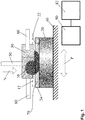
- a device for evaluating a noise behavior of a fluid 70 is shown schematically.
- the device comprises a base body 20 which is fastened on a platform 40.
- the base body 20 is shown in section.
- the device also comprises a counter body 10 which can be moved relative to a base body 20.
- a sufficient quantity of the fluid 70 to be assessed is located in a space between the base body 20 and the counter body 10.
- the fluid is a brake fluid.
- the platform 40 can be temperature controlled in order to simulate practical applications at higher or lower temperatures.
- the base body 20 is made of a metal and has approximately the shape of a circular disk. On a side facing away from the platform 40, the base body 20 has a flat surface 22. In the present case, the flat surface 22 is surrounded by a circumferential elevation 24. The elevation 24, together with the flat surface 22, forms a trough-like depression in the base body 20, which is used to receive the fluid 70 to be assessed. The elevation 24 of the base body 20 can also be omitted, in particular if droplet wetting of the flat surface 22 with the fluid 70 to be assessed is sufficient.
- the counter body 10 is made of an elastomer and designed as a piece from a cord material.
- the counter body 10 is designed to be circular-cylindrical and has a central axis 12.
- the central axis 12 of the counter body 10 runs parallel to the flat surface 22 of the base body 20.
- the counter body 10 protrudes into the tub-like Recess of the base body 20 and is in contact with the fluid 70 located there.
- the counter body 10 is firmly clamped in a holder 30.
- the holder 30 prevents the counter body 10 from rotating about its central axis 12.
- a coupling strut 50 is attached to the holder 30.
- the coupling strut 50 is a cylindrical rod and protrudes away from the holder 30 on a side facing away from the base body 20.
- the coupling strut 50 is used to apply a normal force N to the counter body 10.
- the normal force N is directed towards the base body 20 and is at right angles on the flat surface 22 of the base body 20.
- the normal force N is thus perpendicular to the central axis 12 of the counter body 10 .
- a force measuring system measures the normal force N and allows feedback for a control loop.
- the normal force N can be reproduced and tracked.
- the tracking is necessary in particular in the case of relaxing elastomer materials of the counter body 10.
- the holder 30 is also connected to a drive system 60.
- the drive system 60 comprises two cylindrical rods which are each connected to the holder 30 by means of a coupling (not shown here).
- the drive system 60 enables the holder 30 to be moved in a direction perpendicular to the central axis 12 of the counter body 10 and parallel to the flat surface 22 of the base body 20.
- the counter body 10 is also perpendicular to its central axis M and parallel to the flat surface 22 of the Base body 20 movable.
- the drive system 60 also includes an electrodynamic voice coil, not shown here, and in particular enables a translatory oscillating movement of the counter body 10 relative to the base body 20.
- An eccentric drive and a crank drive are also conceivable.
- the drive system 60 further comprises a position measuring system, not shown here, by means of which a positioning P of the counter body 10 relative to the base body 20 can be recorded. In the present case, the drive system 60 executes a stroke of 3 mm at a frequency of 2 Hz.
- the platform 40 includes sensors, not shown here, for measuring the frictional force RK.
- the sensors for measuring the frictional force RK are connected to a recording unit 80.
- the receiving unit 80 is also with the Distance measuring system of the drive system 60 and connected to the force measuring system for the normal force N.
- Measured values of the frictional force RK, measured values of the positioning P and measured values of the normal force N are transmitted to the recording unit 60 in a time-synchronous manner.
- the measured values of the frictional force RK are direction-dependent and, depending on the direction of the frictional force RK, positive or negative.
- the recording unit 80 serves to record the frictional force RK and / or the coefficient of friction RW between the counter body 10 and the base body 20 as a function of the positioning P of the counter body 10 relative to the base body 20.
- the recording unit 80 in particular takes synchronous measured values of the friction force RK, the Normal force N and the positioning P.
- the recording unit 80 is connected to a computing unit 82.
- the computing unit 82 is used to determine a friction force fluctuation RKS from the friction force RK and to determine a friction coefficient fluctuation RWS from the friction coefficient RW. Furthermore, the computing unit 82 serves to calculate a fluctuation mean value SM from the friction force fluctuation RKS and from the friction value fluctuation RWS.
- the counter body 10 When carrying out the method, the counter body 10 is moved relative to the base body, while the fluid 70 is located between the counter body 10 and the base body 20.
- the counter body is moved in a translatory oscillating manner at right angles to its central axis 12 and parallel to the flat surface 22 of the base body 20, with its central axis 12 running parallel to the flat surface 22.
- a normal force N is applied to the counter body 10, which is directed in the direction of the base body 20 and is at right angles on the flat surface 22.
- a frictional force RK between the counter body 10 and the base body 20 is recorded synchronously as a function of the positioning P of the counter body 10 relative to the base body 20.
- the frictional force RK between the counter body 10 and the base body 20 is presently recorded during a complete cycle of the oscillating movement.
- the coefficient of friction RW is calculated as a quotient from the frictional force RK and the normal force N. With a constant normal force N, the coefficient of friction RW is directly proportional to the friction force RK.
- Figure 2 shows a graphic representation of the coefficient of friction RK of the fluid 70 as a function of the positioning P during a complete cycle. Depending on the direction of the frictional force RK, the coefficient of friction RW is plotted positively or negatively.
- an upper envelope OE and a lower envelope UE are calculated for the coefficient of friction RW.
- Figure 3 shows a graphic representation of the coefficient of friction RK from Figure 2 with the upper envelope OE and the lower envelope UE.
- an upper envelope OE and a lower envelope UE can also be calculated for the frictional force RK.
- a friction coefficient fluctuation RWS is then determined from a difference between the upper envelope OE and the lower envelope UE of the coefficient of friction RW.
- Figure 4 shows a graphic representation of the coefficient of friction fluctuation RW as the difference between that of the upper envelope OE and the lower envelope UE Figure 3 .
- a friction force fluctuation RKS can also be determined from a difference between the upper envelope OE and the lower envelope UE of the frictional force RK.
- a mean fluctuation value (SM) is then calculated from the fluctuation in the coefficient of friction RWS and / or from the fluctuation in the friction force RKS.
- the fluctuation mean value SM calculated from the fluctuation in the coefficient of friction RWS is in Figure 4 also shown.
- the fluctuation mean value SM calculated according to the first variant for the fluid 70 has a numerical value of approximately 0.07 in the present case.
- a sliding mean value GM is calculated for the coefficient of friction RW.
- Figure 5 shows a graphic representation of the coefficient of friction RK from Figure 2 with moving average GM.
- a sliding mean value GM for the frictional force RK can also be calculated.
- a friction coefficient fluctuation RWS is then determined from a distance between the coefficient of friction RW and the sliding mean value GM.
- Figure 6 shows a graphic representation of the coefficient of friction fluctuation RW as a distance from the moving average value GM Figure 5 .
- a friction force fluctuation RKS can also be determined from a distance between the frictional force RK and the sliding mean value GM.
- a mean fluctuation value SM is then calculated from the fluctuation in the coefficient of friction RWS and / or from the fluctuation in the friction force RKS.
- the fluctuation mean value SM calculated from the fluctuation in the coefficient of friction RWS is in Figure 6 also shown.
- the fluctuation mean value SM calculated according to the second variant for the fluid 70 has a numerical value of approximately 0.03 in the present case.
- the frictional force RK can also be absorbed during several cycles of the oscillating movement.
- a temporary average fluctuation value SM is calculated for each cycle, and an overall average fluctuation value SM is calculated from the temporary average fluctuation values SM, in particular by averaging.
- Figure 7 shows a graphic representation of the coefficient of friction RK of another fluid 70 as a function of the positioning P during a complete cycle. From a visual comparison between Figure 2 and Figure 7 it can already be seen that the other fluid 70 has a lower mean fluctuation value SM.
- An acoustic sound recording can be carried out parallel to the recording of the frictional force RK, the determination of the friction coefficient fluctuation RWS and the calculation of the fluctuation mean value SM. It is found that the acoustic sound recording of the noise behavior of the fluid 70 correlates with the calculated mean fluctuation value SM.
- the calculated mean fluctuation value SM is therefore a measure of an amplitude of the noise generated by the fluid 70. The greater the mean fluctuation value SM, the higher the volume of this noise.
Description
Die Erfindung betrifft ein Verfahren zur Bewertung eines Geräuschverhaltens eines Fluids nach Anspruch 1, insbesondere einer Bremsflüssigkeit. Die Erfindung betrifft ferner eine Vorrichtung zur Bewertung eines Geräuschverhaltens eines Fluids nach Anspruch 12, insbesondere einer Bremsflüssigkeit.The invention relates to a method for evaluating the noise behavior of a fluid according to claim 1, in particular a brake fluid. The invention also relates to a device for evaluating the noise behavior of a fluid according to
Fluide, beispielsweise viskose Flüssigkeiten wie Schmieröle oder Bremsflüssigkeiten, verursachen oftmals störende Geräusche beim Einsatz in einem technischen System, beispielsweise in einer Pumpe oder einem Kompressor. Eine einfache quantifizierende Prüfung des Geräuschverhaltens von Fluiden ist in bisherigen Prüfketten zur Prüfung von manuell oder elektromotorisch angetriebenen Pumpen, welche Druck und Durchflussmenge in einem Fahrzeugbremssystem bereitstellen, nicht vorhanden. Auffälligkeiten mit Geräuschen durch ein Fluidum werden meist erst in einem späten Entwicklungsstadium oder im Praxiseinsatz festgestellt.Fluids, for example viscous liquids such as lubricating oils or brake fluids, often cause disturbing noises when used in a technical system, for example in a pump or a compressor. A simple quantifying test of the noise behavior of fluids is not available in previous test chains for testing manually or electric motor-driven pumps, which provide pressure and flow rate in a vehicle brake system. Anomalies with noises caused by a fluid are usually only detected at a late stage of development or in practical use.
Aus der DIN 51384 ("
In der Druckschrift "
Die Eigenschaften und das Verhalten der Grundkörper und Gegenkörper sind von deren Materialien ebenso wie von deren Gestalt dieser abhängig.The properties and behavior of the base body and counter body are dependent on their materials as well as on their shape.
Grundkörper aus einem Metallwerkstoff besitzen in ihrer Eigenschaft im Wesentlichen eine Oberflächentopographie, welche sich zumindest mit Verfahren nach ISO-Standards [ISO 4287 (s. 2010) und die DIN EN ISO 13565-2] beschreiben lässt.
In dem Lehrbuch "
In dem Lehrbuch "
In der
Die Bestimmung der tribologischen Eigenschaften von Fluiden, insbesondere von Bremsflüssigkeiten, in einem technischen System benötigt eine detaillierte Analyse der Systemelemente. Diese sind der Grundkörper und der Gegenkörper, das auf sein Geräuschverhalten zu untersuchende Fluid sowie die Umgebungsbedingungen. Die Umgebungsbedingungen können unter anderem unterschiedliche Temperaturen und/oder atmosphärische Bedingungen umfassen.The determination of the tribological properties of fluids, in particular of brake fluids, in a technical system requires a detailed analysis of the system elements. These are the base body and the counter body, the fluid to be examined for its noise behavior and the ambient conditions. The ambient conditions can include, among other things, different temperatures and / or atmospheric conditions.
Da die Prüfkette, insbesondere für Bremsflüssigkeiten in Fahrzeugbremssystemen, hohen Aufwand bei der Prüfung von neuen Bremsflüssigkeiten bzw. von neuen Formulierungen von Glykol-basierten Flüssigkeiten mit Additiven verursacht, ergibt sich ein Bedarf für ein vereinfachtes Prüfsystem, im Besonderen für eine Vorrichtung zur Bewertung des Geräuschverhaltens. Der Aufwand innerhalb der Prüfkette wird vor allem durch das Testen der Flüssigkeiten in kompletten Pumpen-Aggregaten verursacht.Since the test chain, especially for brake fluids in vehicle brake systems, causes a great deal of effort when testing new brake fluids or new formulations of glycol-based fluids with additives, there is a need for a simplified test system, in particular for a device for evaluating noise behavior . The effort within the test chain is mainly caused by testing the liquids in complete pump units.
Der Prüfaufwand steigt mit der Komplexität eines Aggregats und dessen geforderten Eigenschaften. Über diese Eigenschaften ergibt sich eine Parametervielfalt, die abzubilden ist, um den Realbetrieb, beispielsweise von Pumpenaggregaten in Kraftfahrzeugen, nachzustellen.The testing effort increases with the complexity of a unit and its required properties. These properties result in a variety of parameters that must be mapped in order to simulate real operation, for example of pump units in motor vehicles.
Der Fokus der vorliegenden Erfindung liegt auf einer Abstraktion des Einzelsystems mit einem Dichtelement des Pumpenaggregats. Eine Aufgabe der vorliegenden Erfindung ist es, ein Verfahren und eine Vorrichtung zur Bewertung eines Geräuschverhaltens eines Fluids bereitzustellen, welche die Bedingungen für eine Bremsflüssigkeit in den Dichtelementen eines Hauptbremszylinders abbilden. Im Besonderen sollen das Verfahren und die Vorrichtung der Quantifizierung des Geräuschverhaltens von Bremsflüssigkeiten dienen.The focus of the present invention is on an abstraction of the individual system with a sealing element of the pump assembly. It is an object of the present invention to provide a method and a device for evaluating the noise behavior of a fluid, which map the conditions for a brake fluid in the sealing elements of a master cylinder. In particular, the method and the device are intended to quantify the noise behavior of brake fluids.
Diese Aufgabe wird erfindungsgemäß durch ein Verfahren zur Bewertung eines Geräuschverhaltens eines Fluids, insbesondere einer Bremsflüssigkeit, mit den Merkmalen des Anspruchs 1 gelöst. Vorteilhafte Ausgestaltungen und Weiterbildungen der Erfindung sind auch Gegenstand der Unteransprüche.According to the invention, this object is achieved by a method for evaluating the noise behavior of a fluid, in particular a brake fluid, having the features of claim 1. Advantageous refinements and developments of the invention are also the subject matter of the subclaims.
Entsprechend dem erfindungsgemäßen Verfahren wird ein Gegenkörper relativ zu einem Grundkörper bewegt, während sich das Fluid zwischen dem Gegenkörper und dem Grundkörper befindet. Der Gegenkörper wird dabei entlang einer Oberfläche des Grundkörpers bewegt und das Fluid dient als Schmiermittel.According to the method according to the invention, a counter body is moved relative to a base body while the fluid is located between the counter body and the base body. The counter body is moved along a surface of the base body and the fluid is used as a lubricant.
Während der Bewegung des Gegenkörpers relativ zu dem Grundkörper wird eine Reibungskraft und/oder ein Reibwert zwischen dem Gegenkörper und dem Grundkörper in Abhängigkeit von einer Positionierung des Gegenkörpers relativ zu dem Grundkörper aufgenommen. Insbesondere wird dabei ein Verlauf der Reibungskraft und/oder des Reibwerts aufgenommen.During the movement of the counter body relative to the base body, a frictional force and / or a coefficient of friction between the counter body and the base body is recorded as a function of a positioning of the counter body relative to the base body. In particular, a course of the frictional force and / or the coefficient of friction is recorded.
Die Reibungskraft sowie der Reibwert sind dabei in der Regel nicht konstant sondern unterliegen Schwankungen. Es wurde herausgefunden, dass die Schwankungen der Reibungskraft sowie des Reibwerts mit dem Geräuschverhalten des Fluids korrelieren und insbesondere ursächlich für eine Geräuschentwicklung sind. Daher wird aus der aufgenommenen Reibungskraft eine Reibungskraftschwankung und/oder aus dem aufgenommenen Reibwert eine Reibwertschwankung bestimmt.The frictional force and the coefficient of friction are usually not constant but are subject to fluctuations. It was found that the fluctuations in the frictional force and the coefficient of friction correlate with the noise behavior of the fluid and are in particular the cause of noise generation. Therefore, a friction force fluctuation is determined from the recorded friction force and / or a friction value fluctuation is determined from the recorded friction value.
Anschließend wird aus der zuvor bestimmten Reibungskraftschwankung und/oder aus der zuvor bestimmten Reibwertschwankung ein Schwankungsmittelwert berechnet.A mean fluctuation value is then calculated from the previously determined friction force fluctuation and / or from the previously determined friction coefficient fluctuation.
Der so berechnete Schwankungsmittelwert ist ein Maß für eine Amplitude eines von dem Fluid erzeugten Geräuschs, also für die Lautstärke des Geräuschs. Mittels des Schwankungsmittelwerts kann somit eine Bewertung, insbesondere eine quantitative Bewertung, des Geräuschverhaltens des Fluids, durchgeführt werden.The mean fluctuation value calculated in this way is a measure of an amplitude of a noise generated by the fluid, that is to say for the volume of the noise. An evaluation, in particular a quantitative evaluation, of the noise behavior of the fluid can thus be carried out by means of the mean fluctuation value.
Durch das erfindungsgemäße Verfahren ist die Prüfung von Fluiden, insbesondere von Flüssigkeiten wie Bremsflüssigkeiten, zur Bewertung des Geräuschverhaltens wesentlich erleichtert. Insbesondere ist eine Aufnahme und Auswertung von Schallwellen des durch das Fluid erzeugten Geräuschs nicht zwangsläufig erforderlich. Das Verfahren ist technisch einfach und kostengünstig durchführbar. Die Prüfkette einer Anwendung kann durch das erfindungsgemäße Verfahren vorteilhaft ergänzt und vereinfacht werden. Der erforderliche Prüfaufwand bei wesentlichen Einflussgrößen zum Auffinden einer geräuschunauffälligen Kombination aus Fluid und Werkstoffen kann durch das erfindungsgemäße Verfahren deutlich verringert werden.The method according to the invention makes it considerably easier to test fluids, in particular fluids such as brake fluids, for evaluating the noise behavior. In particular, it is not absolutely necessary to record and evaluate sound waves of the noise generated by the fluid. The process is technically simple and inexpensive to carry out. The test chain of an application can advantageously be supplemented and simplified by the method according to the invention. The testing effort required for essential influencing variables to find a noise-inconspicuous combination of fluid and materials can be significantly reduced by the method according to the invention.
Bei der Bewertung des Geräuschverhaltens von Flüssigkeiten wie Bremsflüssigkeiten mit dem erfindungsgemäßen Verfahren wurde eine annähernd eindeutige Übereinstimmung mit bekannten Praxisfällen erzielt. Bremsflüssigkeiten, welche mit dem erfindungsgemäßen Verfahren als auffällig und laut bewertet wurden, zeigten sich auch beim Einsatz in einem Serienfahrzeug messbar laut und auffällig.When evaluating the noise behavior of fluids such as brake fluids using the method according to the invention, an approximately unambiguous correspondence with known practical cases was achieved. Brake fluids which were evaluated as conspicuous and loud using the method according to the invention were also found to be measurably loud and conspicuous when used in a series vehicle.
Gemäß einer vorteilhaften Weiterbildung der Erfindung wird während der Bewegung des Gegenkörpers relativ zu dem Grundkörper eine Normalkraft auf den Gegenkörper aufgebracht, welche in Richtung auf den Grundkörper zu gerichtet ist. Die Normalkraft wirkt somit rechtwinklig zu der Richtung der Bewegung des Gegenkörpers relativ zu dem Grundkörper. Mittels der Normalkraft kann eine definierte Belastung zwischen Grundkörper und Gegenkörper aufgebracht werden. Idealerweise lässt sich dies Belastung dynamisch während eines Tests verändern um Geräuschentstehung und Dichtungsbelastung zu vergleichen. Dabei kann die Normalkraft in Stufen, beispielsweise beginnend bei 5 N und Intervallen von 2 Minuten um jeweils 5 N bis zu 20 N gesteigert werden. Für eine genauere Differenzierung kann die Belastung angepasst werden.According to an advantageous development of the invention, during the movement of the counter body relative to the base body, a normal force is applied to the counter body which is directed towards the base body. The normal force thus acts at right angles to the direction of movement of the counter body relative to the base body. By means of the normal force, a defined load can be applied between the base body and the counter body. Ideally, this load can be changed dynamically during a test in order to compare noise generation and seal load. The normal force can be increased by 5 N up to 20 N in steps, for example starting at 5 N and at intervals of 2 minutes. The load can be adjusted for a more precise differentiation.
Vorteilhaft wird der Reibwert aus der Reibungskraft und der Normalkraft berechnet. Insbesondere wird der Reibwert als Quotient aus der Reibungskraft und der Normalkraft berechnet. Wenn während der Bewegung des Gegenkörpers relativ zu dem Grundkörper eine konstante Normalkraft aufgebracht wird, so ist der Reibwert proportional zu der Reibungskraft und damit verhältnismäßig einfach zu berechnen.The coefficient of friction is advantageously calculated from the frictional force and the normal force. In particular, the coefficient of friction is calculated as the quotient of the frictional force and the normal force. If a constant normal force is applied during the movement of the counter body relative to the base body, the coefficient of friction is proportional to the friction force and is therefore relatively easy to calculate.
Die in einem tribologischen System obligatorische Relativbewegung und Belastung zwischen Grundkörper und Gegenkörper ist im Besonderen bei der Bewertung des Geräuschverhaltens der jeweiligen Anwendung anzupassen. Die Anwendung in einem Hauptbremszylinder eines Fahrzeugs setzt eine oszillierende Bewegung mit einem definiertem Hub und einer definierter Frequenz voraus.The relative movement and load between the base body and the counter body, which is mandatory in a tribological system, must be adapted to the respective application in particular when evaluating the noise behavior. The application in a master brake cylinder of a vehicle requires an oscillating movement with a defined stroke and a defined frequency.
Gemäß einer bevorzugten Weiterbildung der Erfindung wird daher der Gegenkörper relativ zu dem Grundkörper oszillierend bewegt. Insbesondere wird der Gegenkörper dabei translatorisch bewegt.According to a preferred development of the invention, the counter body is therefore moved in an oscillating manner relative to the base body. In particular, the counter body is moved in a translatory manner.
Gemäß einer vorteilhaften Ausgestaltung der Erfindung werden die Reibungskraft und/oder der Reibwert zwischen dem Gegenkörper und dem Grundkörper während eines vollständigen Zyklus dieser oszillierenden Bewegung aufgenommen. Der Gegenkörper befindet sich dabei am Anfang des Zyklus in der gleichen Positionierung relativ zu dem Grundkörper wie am Ende des Zyklus. Dadurch kann das Geräuschverhalten des Fluids verhältnismäßig genau bewertet werden, wobei die Menge der aufgenommenen Daten und der erforderlich Aufwand zur Berechnung des Schwankungsmittelwerts verhältnismäßig gering sind.According to an advantageous embodiment of the invention, the frictional force and / or the coefficient of friction between the counter body and the base body are recorded during a complete cycle of this oscillating movement. At the beginning of the cycle, the counter body is in the same position relative to the base body as at the end of the cycle. As a result, the noise behavior of the fluid can be assessed relatively precisely, the amount of data recorded and the effort required to calculate the mean fluctuation value being relatively low.
Gemäß einer anderen vorteilhaften Ausgestaltung der Erfindung werden die Reibungskraft und/oder der Reibwert zwischen dem Gegenkörper und dem Grundkörper während mehrerer Zyklen dieser oszillierenden Bewegung aufgenommen. Der Gegenkörper befindet sich dabei am Anfang der Zyklen bevorzugt in der gleichen Positionierung relativ zu dem Grundkörper wie am Ende der Zyklen. Durch die Aufnahme einer größeren Menge von Daten und Erhöhung des Aufwands zur Berechnung des Schwankungsmittelwerts kann das Geräuschverhalten des Fluids noch genauer bewertet werden.According to another advantageous embodiment of the invention, the frictional force and / or the coefficient of friction between the counter body and the base body are recorded during several cycles of this oscillating movement. At the beginning of the cycles, the counter body is preferably in the same position relative to the base body as at the end of the cycles. By recording a larger amount of data and increasing the effort required to calculate the mean fluctuation value, the noise behavior of the fluid can be assessed even more precisely.
Gemäß einer Ausführungsform der Erfindung werden zu der Reibungskraft und/oder zu dem Reibwert eine obere Einhüllende und eine untere Einhüllende berechnet. Die obere Einhüllende und die untere Einhüllende sind Kurven, welche bei einer graphischen Darstellung den Verlauf der Reibungskraft und/oder des Reibwerts einhüllen.According to one embodiment of the invention, an upper envelope and a lower envelope are calculated for the frictional force and / or for the coefficient of friction. The upper envelope and the lower envelope are curves which, in a graphic representation, envelop the course of the frictional force and / or the coefficient of friction.
Aus einer Differenz zwischen der oberen Einhüllenden und der unteren Einhüllenden wird dann die Reibungskraftschwankung und/oder die Reibwertschwankung bestimmt. Die obere Einhüllende ist dabei stets größer als die untere Einhüllende. Somit ist die Differenz zwischen der oberen Einhüllenden und der unteren Einhüllenden stets positiv.The friction force fluctuation and / or the friction coefficient fluctuation is then determined from a difference between the upper envelope and the lower envelope. The upper envelope is always larger than the lower envelope. Thus the difference between the upper envelope and the lower envelope is always positive.
Gemäß einer anderen möglichen Ausführungsform der Erfindung wird zu der Reibungskraft und/oder zu dem Reibwert ein gleitender Mittelwert berechnet.According to another possible embodiment of the invention, a sliding mean value is calculated for the frictional force and / or for the coefficient of friction.
Der gleitende Mittelwert ist eine Kurve, um welche bei einer graphischen Darstellung der Verlauf der Reibungskraft und/oder des Reibwerts oszilliert. Der als y(n) bezeichnete gleitende Mittelwert entspricht vorliegend einem Mittelwert in einem Fenster mit einer definierten Breite, beispielsweise 50 Messwerte, welche als windowSize bezeichnet wird. Der Index n läuft über die Anzahl der Messwerte in dem Messwertevektor x. ![]()
![]()
Aus einem Abstand der Reibungskraft und/oder des Reibwerts zu dem gleitenden Mittelwert werden dann die Reibungskraftschwankung und/oder die Reibwertschwankung bestimmt. Der Abstand der Reibungskraft und/oder des Reibwerts zu dem gleitenden Mittelwert kann beispielsweise als Betrag der Differenz zwischen der Reibungskraft und/oder dem Reibwert zu dem gleitenden Mittelwert berechnet werden. Der Abstand der Reibungskraft und/oder des Reibwerts zu dem gleitenden Mittelwert kann beispielsweise auch als Quadrat der Differenz zwischen der Reibungskraft und/oder dem Reibwert zu dem gleitenden Mittelwert berechnet werden. Somit ist die Differenz zwischen der Reibungskraft und/oder dem Reibwert zu dem gleitenden Mittelwert stets positiv.The friction force fluctuation and / or the friction coefficient fluctuation are then determined from a distance between the frictional force and / or the coefficient of friction and the moving average. The distance between the frictional force and / or the coefficient of friction and the moving average can be calculated, for example, as the amount of the difference between the frictional force and / or the coefficient of friction and the moving average. The distance between the frictional force and / or the coefficient of friction and the moving average can also be calculated, for example, as the square of the difference between the frictional force and / or the coefficient of friction and the moving average. Thus, the difference between the frictional force and / or the coefficient of friction to the moving average is always positive.
Vorzugsweise ist der Gegenkörper kreiszylindrisch ausgestaltet und weist eine Mittelachse auf, um welche der Gegenkörper rotationssymmetrisch ist. Vorzugsweise weist der Grundkörper eine ebene Fläche auf. Dabei wird der Gegenkörper rechtwinklig zu der Mittelachse und parallel zu der ebenen Fläche des Grundkörpers bewegt, wobei die Mittelachse des Gegenkörpers parallel zu der ebenen Fläche des Grundkörpers verläuft. Insbesondere wird der Gegenkörper dabei translatorisch bewegt, wobei keine Rotation um die Mittelachse erfolgt.The counter body is preferably designed as a circular cylinder and has a central axis about which the counter body is rotationally symmetrical. The base body preferably has a flat surface. The counter body is moved at right angles to the central axis and parallel to the flat surface of the base body, the central axis of the counter body running parallel to the flat surface of the base body. In particular, the counter body is moved in a translatory manner, with no rotation occurring about the central axis.
Zusätzlich wird eine akustische Tonaufnahme während der Bewegung des Gegenkörpers relativ zu dem Grundkörper in der Nähe des Kontaktes zwischen Grundkörper und Gegenkörper durchgeführt. Insbesondere wird durch die Tonaufnahme das entstehende Geräusch über mehrere Zyklen der Bewegung, beziehungsweise über einen bestimmten Zeitraum, aufgenommen.In addition, an acoustic sound recording is carried out during the movement of the counter body relative to the base body in the vicinity of the contact between the base body and the counter body. In particular, the sound is recorded over several cycles of movement or over a certain period of time.
Das hier beschriebene erfindungsgemäße Verfahren findet vorteilhaft Verwendung zur Bewertung des Geräuschverhaltens einer (hoch)viskosen Flüssigkeit, insbesondere einer Bremsflüssigkeit. Insbesondere kann das Geräuschverhalten der Bremsflüssigkeit in einem Bremszylinder eines Fahrzeugs, speziell eines Kraftfahrzeugs, bewertet werden.The method according to the invention described here is advantageously used for evaluating the noise behavior of a (highly) viscous fluid, in particular a brake fluid. In particular, the noise behavior of the brake fluid in a brake cylinder of a vehicle, especially a motor vehicle, can be assessed.
Die Aufgabe wird erfindungsgemäß auch durch eine Vorrichtung zur Bewertung eines Geräuschverhaltens eines Fluids, insbesondere einer Bremsflüssigkeit, mit den Merkmalen der Ansprüche gelöst. Vorteilhafte Ausgestaltungen und Weiterbildungen der Erfindung sind Gegenstand der Unteransprüche.According to the invention, the object is also achieved by a device for evaluating the noise behavior of a fluid, in particular a brake fluid, having the features of the claims. Advantageous refinements and developments of the invention are the subject matter of the subclaims.
Die erfindungsgemäße Vorrichtung umfasst einen Grundkörper und einen Gegenkörper, welcher relativ zu dem Grundkörper bewegbar ist, während sich das Fluid zwischen dem Gegenkörper und dem Grundkörper befindet. Der Gegenkörper ist dabei entlang einer Oberfläche des Grundkörpers bewegbar und das Fluid dient bei einer solchen Bewegung als Schmiermittel.The device according to the invention comprises a base body and a counter body which can be moved relative to the base body while the fluid is located between the counter body and the base body. The counter body can be moved along a surface of the base body and the fluid serves as a lubricant during such a movement.
Zum Ausführen der Bewegung des Gegenkörpers relativ zu dem Grundkörper umfasst die Vorrichtung ein Antriebssystem, mit welchem insbesondere eine translatorisch oszillierende Bewegung möglich ist. Das Antriebssystem dient auch dazu, die elastische Nachgiebigkeit des Systems der praktischen Anwendung, beispielsweise in einen Bremszylinder, möglichst nachzubilden. Im Besonderen kann das Antriebssystem hierzu ein Schwingspulenantrieb zur Nachbildung der Antriebsbewegung aufweisen.In order to execute the movement of the counter body relative to the base body, the device comprises a drive system with which, in particular, a translatory oscillating movement is possible. The drive system also serves to simulate the elastic flexibility of the system of practical application, for example in a brake cylinder, as far as possible. In particular, the drive system can have a voice coil drive for this purpose to simulate the drive movement.
Die erfindungsgemäße Vorrichtung umfasst ferner (mindestens) eine Aufnahmeeinheit zur Aufnahme einer Reibungskraft und/oder eines Reibwerts zwischen dem Gegenkörper und dem Grundkörper in Abhängigkeit von einer Positionierung des Gegenkörpers relativ zu dem Grundkörper. Mittels der Aufnahmeeinheit kann insbesondere ein Verlauf der Reibungskraft und/oder des Reibwerts aufgenommen werden. Die Aufnahmeeinheit gestattet eine hochaufgelöste Datenaufzeichnung der Bewegungsamplitude und der Reibungskraft zwischen dem Grundkörper und dem Gegenkörper.The device according to the invention further comprises (at least) one receiving unit for receiving a frictional force and / or a coefficient of friction between the counter body and the base body as a function of a positioning of the counter body relative to the base body. In particular, a profile of the frictional force and / or the coefficient of friction can be recorded by means of the recording unit. The recording unit allows high-resolution data recording of the movement amplitude and the frictional force between the base body and the counter body.
Die erfindungsgemäße Vorrichtung umfasst vorzugsweise ferner eine Recheneinheit zur Bestimmung einer Reibungskraftschwankung aus der Reibungskraft und/oder einer Reibwertschwankung aus dem Reibwert. Die Recheneinheit dient auch zur Berechnung eines Schwankungsmittelwerts aus der Reibungskraftschwankung und/oder aus der Reibwertschwankung.The device according to the invention preferably further comprises a computing unit for determining a friction force fluctuation from the friction force and / or a friction value fluctuation from the friction value. The arithmetic unit also serves to calculate a mean fluctuation value from the fluctuation in the frictional force and / or from the fluctuation in the coefficient of friction.
Mit Hilfe der erfindungsgemäßen Vorrichtung kann für die Fluidentwicklung vorab eine Geräuschauffälligkeit mit einfachen Mitteln identifiziert werden. Die erfindungsgemäße Vorrichtung ist einfach und kostengünstig herzustellen und auf mindestens jeder Prüfmaschine nutzbar, welche in der DIN 51384 beschrieben ist.With the aid of the device according to the invention, an abnormality in noise can be identified in advance with simple means for the fluid development. The device according to the invention is simple and inexpensive to manufacture and can be used on at least every testing machine that is described in DIN 51384.
Generell soll ein Gegenkörper zur Anwendung kommen, welcher eine zylindrische Form hat und quer zu seiner Zylinderachse bewegt wird. Die Gründe hierfür sind in dem Lehrbuch "
Vorzugsweise ist der Gegenkörper kreiszylindrisch ausgestaltet und weist eine Mittelachse auf, um welche der Gegenkörper rotationssymmetrisch ist. Vorzugsweise weist der Grundkörper eine ebene Fläche auf. Dabei ist der Gegenkörper rechtwinklig zu der Mittelachse und parallel zu der ebenen Fläche des Grundkörpers bewegbar, wobei die Mittelachse des Gegenkörpers parallel zu der ebenen Fläche des Grundkörpers verläuft. Insbesondere erfolgt die Bewegung des Gegenkörpers dabei translatorisch und ohne Rotation um die Mittelachse.The counter body is preferably designed as a circular cylinder and has a central axis about which the counter body is rotationally symmetrical. The base body preferably has a flat surface. The counter body can be moved at right angles to the central axis and parallel to the flat surface of the base body, the central axis of the counter body running parallel to the flat surface of the base body. In particular, the counter body is moved in a translatory manner and without rotation about the central axis.
Bevorzugt ist der Gegenkörper aus einem Elastomer gefertigt, und der Grundkörper ist aus einem Metall gefertigt. Die Empfindlichkeit der Vorrichtung kann unter anderem durch die Beschaffenheit der Metalloberfläche des Grundkörpers eingestellt werden. Die Oberfläche des Grundkörpers sollte für eine sichere Korrelation mit dem System der praktischen Anwendung, beispielsweise einen Bremszylinder, angepasst werden.The counter body is preferably made from an elastomer and the base body is made from a metal. The sensitivity of the device can be adjusted, among other things, by the nature of the metal surface of the base body. The surface of the base body should be adapted for a reliable correlation with the system of the practical application, for example a brake cylinder.
Die hier beschriebene erfindungsgemäße Vorrichtung findet vorteilhaft Verwendung zur Bewertung des Geräuschverhaltens einer viskosen Flüssigkeit, insbesondere Bremsflüssigkeit. Insbesondere kann das Geräuschverhalten der Bremsflüssigkeit in einem Bremszylinder eines Fahrzeugs, speziell eines Kraftfahrzeugs, bewertet werden.The device according to the invention described here is advantageously used for evaluating the noise behavior of a viscous fluid, in particular brake fluid. In particular, the noise behavior of the brake fluid in a brake cylinder of a vehicle, especially a motor vehicle, can be evaluated.
Im Folgenden ist die Erfindung anhand eines in den Figuren dargestellten vorteilhaften Ausführungsbeispiels näher erläutert. Die Erfindung wird ferner in den Ansprüchen präzisiert.The invention is explained in more detail below using an advantageous exemplary embodiment shown in the figures. The invention is further specified in the claims.
Es zeigen:
- Figur 1:
- eine schematische teilgeschnittene Darstellung einer Vorrichtung zur Bewertung eines Geräuschverhaltens eines Fluids;
- Figur 2:
- eine graphische Darstellung eines Reibwerts eines Fluids in Abhängigkeit von der Positionierung;
- Figur 3:
- eine graphische Darstellung des Reibwerts aus
Figur 2 mit Einhüllenden; - Figur 4:
- eine graphische Darstellung einer Reibwertschwankung als Differenz zwischen den Einhüllenden aus
Figur 3 ; - Figur 5:
- eine graphische Darstellung des Reibwerts aus
Figur 2 mit gleitendem Mittelwert; - Figur 6:
- eine graphische Darstellung einer Reibwertschwankung als Abstand zu dem gleitendem Mittelwert aus
Figur 5 und - Figur 7:
- eine graphische Darstellung eines Reibwerts eines anderen Fluids in Abhängigkeit von der Positionierung;
- Figure 1:
- a schematic partially sectioned representation of a device for evaluating a noise behavior of a fluid;
- Figure 2:
- a graphical representation of a coefficient of friction of a fluid as a function of the positioning;
- Figure 3:
- a graphic representation of the coefficient of friction
Figure 2 with envelopes; - Figure 4:
- a graphical representation of a coefficient of friction fluctuation as the difference between the envelopes
Figure 3 ; - Figure 5:
- a graphic representation of the coefficient of friction
Figure 2 with moving average; - Figure 6:
- a graphical representation of a fluctuation in the coefficient of friction as a distance to the moving average
Figure 5 and - Figure 7:
- a graphic representation of a coefficient of friction of another fluid as a function of the positioning;
In
Der Grundkörper 20 ist aus einem Metall gefertigt und weist annähernd die Form einer Kreisscheibe auf. Auf einer der Plattform 40 abgewandten Seite weist der Grundkörper 20 eine ebene Fläche 22 auf. Die ebene Fläche 22 ist vorliegend von einer umlaufenden Erhöhung 24 umgeben. Die Erhöhung 24 bildet zusammen mit der ebenen Fläche 22 eine wannenähnliche Vertiefung des Grundkörpers 20, welche zur Aufnahme des zu bewertenden Fluids 70 dient. Die Erhöhung 24 des Grundkörpers 20 kann auch entfallen, insbesondere wenn eine Tropfenbenetzung der ebenen Fläche 22 mit dem zu bewertenden Fluid 70 ausreichend ist.The
Der Gegenkörper 10 ist aus einem Elastomer gefertigt und als Stück aus einem Schnurmaterial ausgeführt. Der Gegenkörper 10 ist kreiszylindrisch ausgestaltet und weist eine Mittelachse 12 auf. Die Mittelachse 12 des Gegenkörpers 10 verläuft parallel zu der ebenen Fläche 22 des Grundkörpers 20. Der Gegenkörper 10 ragt in die wannenähnliche Vertiefung des Grundkörpers 20 hinein und steht dabei in Kontakt mit dem dort befindlichen Fluid 70.The
Der Gegenkörper 10 ist in eine Halterung 30 fest eingespannt. Unter anderem verhindert die Halterung 30 eine Rotation des Gegenkörpers 10 um seine Mittelachse 12. An der Halterung 30 ist eine Kopplungsstrebe 50 angebracht. Die Kopplungsstrebe 50 ist vorliegend ein zylindrischer Stab und ragt auf einer dem Grundkörper 20 abgewandten Seite von der Halterung 30 weg. Die Kopplungsstrebe 50 dient zum Aufbringen einer Normalkraft N auf den Gegenkörper 10. Die Normalkraft N ist dabei auf den Grundkörper 20 zu gerichtet und steht rechtwinklig auf der ebenen Fläche 22 des Grundkörpers 20. Die Normalkraft N steht somit rechtwinklig zu der Mittelachse 12 des Gegenkörpers 10.The
Ein hier nicht dargestelltes Kraftmesssystem misst die Normalkraft N und erlaubt dabei eine Rückkopplung für einen Regelkreis. Somit kann die Normalkraft N wiederholbar abgebildet und nachgeführt werden. Die Nachführung ist insbesondere bei relaxierenden Elastomermaterialien des Gegenkörpers 10 erforderlich.A force measuring system, not shown here, measures the normal force N and allows feedback for a control loop. Thus, the normal force N can be reproduced and tracked. The tracking is necessary in particular in the case of relaxing elastomer materials of the
Die Halterung 30 ist ferner mit einem Antriebssystem 60 verbunden. Das Antriebssystem 60 umfasst vorliegend zwei zylindrische Stäbe, welche mittels je einer hier nicht dargestellten Kupplung mit der Halterung 30 verbunden sind. Das Antriebssystem 60 ermöglicht eine Bewegung der Halterung 30 in eine Richtung rechtwinklig zu der Mittelachse 12 des Gegenkörpers 10 und parallel zu der ebenen Fläche 22 des Grundkörpers 20. Somit ist auch der Gegenkörper 10 rechtwinklig zu seiner Mittelachse M und parallel zu der ebenen Fläche 22 des Grundkörpers 20 bewegbar.The
Das Antriebssystem 60 umfasst auch eine hier nicht dargestellte elektrodynamische Schwingspule und ermöglicht insbesondere eine translatorische oszillierende Bewegung des Gegenkörpers 10 relativ zu dem Grundkörper 20. Auch ein Exzenterantrieb sowie ein Kurbelantrieb sind denkbar. Das Antriebssystem 60 umfasst ferner ein hier nicht dargestelltes Wegmesssystem, mittels welchem eine Positionierung P des Gegenkörpers 10 relativ zu dem Grundkörper 20 aufgenommen werden kann. Dabei führt das Antriebssystem 60 vorliegend einen Hub von 3 mm bei einer Frequenz von 2 Hz aus.The
Bei einer Bewegung des Gegenkörpers 10 relativ zu dem Grundkörper 20 entsteht eine Reibungskraft RK. Die Plattform 40 umfasst hier nicht dargestellte Sensoren zur Messung der Reibungskraft RK. Die Sensoren zur Messung der Reibungskraft RK sind an eine Aufnahmeeinheit 80 angeschlossen. Die Aufnahmeeinheit 80 ist ferner mit dem Wegmesssystem des Antriebssystems 60 und mit dem Kraftmesssystem für die Normalkraft N verbunden.When the
Messwerte der Reibungskraft RK, Messwerte der Positionierung P und Messwerte der Normalkraft N werden zeitsynchron zu der Aufnahmeeinheit 60 übertragen. Die Messwerte der Reibungskraft RK sind dabei richtungsabhängig und je nach Richtung der Reibungskraft RK positiv oder negativ.Measured values of the frictional force RK, measured values of the positioning P and measured values of the normal force N are transmitted to the
Aus Messwerten der Reibungskraft RK und Messwerten der Normalkraft N kann ein Reibwert RW als Quotient berechnet werden. Es gilt: ![]()
![]()
Die Aufnahmeeinheit 80 dient zur Aufnahme der Reibungskraft RK und/oder des Reibwerts RW zwischen dem Gegenkörper 10 und dem Grundkörper 20 in Abhängigkeit von der Positionierung P des Gegenkörpers 10 relativ zu dem Grundkörper 20. Die Aufnahmeeinheit 80 nimmt insbesondere synchrone Messwerte der Reibungskraft RK, der Normalkraft N und der Positionierung P auf.The
Die Aufnahmeeinheit 80 ist mit einer Recheneinheit 82 verbunden. Die Recheneinheit 82 dient zur Bestimmung einer Reibungskraftschwankung RKS aus der Reibungskraft RK sowie zur Bestimmung einer Reibwertschwankung RWS aus dem Reibwert RW. Ferner dient die Recheneinheit 82 zur Berechnung eines Schwankungsmittelwerts SM aus der Reibungskraftschwankung RKS sowie aus der Reibwertschwankung RWS.The
Bei der Ausführung des Verfahrens wird der Gegenkörper 10 relativ zu dem Grundkörper bewegt, während sich das Fluid 70 zwischen dem Gegenkörper 10 und dem Grundkörper 20 befindet. Der Gegenkörper wird dabei 10 translatorisch oszillierend rechtwinklig zu seiner Mittelachse 12 und parallel zu der ebenen Fläche 22 des Grundkörpers 20 bewegt, wobei seine Mittelachse 12 parallel zu der ebenen Fläche 22 verläuft. Während dieser Bewegung des Gegenkörpers 10 relativ zu dem Grundkörper 20 wird eine Normalkraft N auf den Gegenkörper 10 aufgebracht, welche in Richtung auf den Grundkörper 20 zu gerichtet ist und rechtwinklig auf der ebenen Fläche 22 steht.When carrying out the method, the
Während der Bewegung des Gegenkörpers 10 relativ zu dem Grundkörper wird eine Reibungskraft RK zwischen dem Gegenkörper 10 und dem Grundkörper 20 in Abhängigkeit von der Positionierung P des Gegenkörpers 10 relativ zu dem Grundkörper 20 zeitsynchron aufgenommen. Die Reibungskraft RK zwischen dem Gegenkörper 10 und dem Grundkörper 20 wird vorliegend während eines vollständigen Zyklus der oszillierenden Bewegung aufgenommen.During the movement of the
Aus der Reibungskraft RK und der Normalkraft N wird der Reibwert RW als Quotient berechnet. Bei einer konstanten Normalkraft N ist der Reibwert RW direkt proportional zu der Reibungskraft RK.
Gemäß einer ersten Variante des Verfahrens werden zu dem Reibwert RW eine obere Einhüllende OE und eine untere Einhüllende UE berechnet.
Aus einer Differenz zwischen der oberen Einhüllenden OE und der unteren Einhüllenden UE des Reibwert RW wird anschließend eine Reibwertschwankung RWS bestimmt.
Alternativ oder zusätzlich kann aus einer Differenz zwischen der oberen Einhüllenden OE und der unteren Einhüllenden UE der Reibungskraft RK auch eine Reibungskraftschwankung RKS bestimmt werden.Alternatively or additionally, a friction force fluctuation RKS can also be determined from a difference between the upper envelope OE and the lower envelope UE of the frictional force RK.
Anschließend wird aus der Reibwertschwankung RWS und/oder aus der Reibungskraftschwankung RKS ein Schwankungsmittelwert (SM) berechnet. Der aus der Reibwertschwankung RWS berechnete Schwankungsmittelwert SM ist in
Gemäß einer zweiten Variante des Verfahrens wird zu dem Reibwert RW ein gleitender Mittelwert GM berechnet.
Aus einem Abstand des Reibwerts RW zu dem gleitenden Mittelwert GM wird anschließend eine Reibwertschwankung RWS bestimmt.
Anschließend wird aus der Reibwertschwankung RWS und/oder aus der Reibungskraftschwankung RKS ein Schwankungsmittelwert SM berechnet. Der aus der Reibwertschwankung RWS berechnete Schwankungsmittelwert SM ist in
Die Reibungskraft RK kann auch während mehrerer Zyklen der oszillierenden Bewegung aufgenommen werden. Dabei wird für jeden Zyklus ein temporärer Schwankungsmittelwert SM berechnet, und aus den temporären Schwankungsmittelwerten SM wird, insbesondere durch Mittelung, ein gesamter Schwankungsmittelwert SM berechnet.The frictional force RK can also be absorbed during several cycles of the oscillating movement. A temporary average fluctuation value SM is calculated for each cycle, and an overall average fluctuation value SM is calculated from the temporary average fluctuation values SM, in particular by averaging.
Parallel zu der Aufnahme der Reibungskraft RK, der Bestimmung der Reibwertschwankung RWS und der Berechnung des Schwankungsmittelwerts SM kann eine akustische Tonaufnahme durchgeführt werden. Es zeigt sich, dass die akustische Tonaufnahme des Geräuschverhaltens des Fluids 70 mit dem berechneten Schwankungsmittelwert SM korreliert. Der berechnete Schwankungsmittelwert SM ist also ein Maß für eine Amplitude des von dem Fluid 70 erzeugten Geräuschs. Je größer der Schwankungsmittelwert SM ist, umso höher ist die Lautstärke dieses Geräuschs.An acoustic sound recording can be carried out parallel to the recording of the frictional force RK, the determination of the friction coefficient fluctuation RWS and the calculation of the fluctuation mean value SM. It is found that the acoustic sound recording of the noise behavior of the fluid 70 correlates with the calculated mean fluctuation value SM. The calculated mean fluctuation value SM is therefore a measure of an amplitude of the noise generated by the
Die Erfindung ist nicht auf die hier beschriebenen Ausführungsbeispiele und die darin hervorgehobenen Aspekte beschränkt. Vielmehr ist innerhalb des durch die Ansprüche angegebenen Bereichs eine Vielzahl von Abwandlungen möglich, die im Rahmen fachmännischen Handelns liegen.The invention is not restricted to the exemplary embodiments described here and the aspects emphasized therein. Rather, a large number of modifications are possible within the range specified by the claims, which are within the scope of expert action.
- 1010
- GegenkörperCounter body
- 1212th
- MittelachseCentral axis
- 2020th
- GrundkörperBase body
- 2222nd
- ebene Flächeflat surface
- 2424
- Erhöhungincrease
- 3030th
- Halterungbracket
- 4040
- Plattformplatform
- 5050
- KopplungsstrebeCoupling strut
- 6060
- AntriebssystemDrive system
- 7070
- FluidFluid
- 8080
- AufnahmeeinheitRecording unit
- 8282
- RecheneinheitArithmetic unit
- PP.
- Positionierungpositioning
- RKRK
- ReibungskraftFrictional force
- RWRW
- ReibwertCoefficient of friction
- RKSRKS
- ReibungskraftschwankungFrictional force fluctuation
- RWSRWS
- ReibwertschwankungFriction coefficient fluctuation
- SMSM
- SchwankungsmittelwertFluctuation mean
- NN
- NormalkraftNormal force
- OEOE
- obere Einhüllendeupper envelope
- UEUE
- untere Einhüllendelower envelope
- GMGM
- gleitender Mittelwertmoving average
Claims (14)
- Method for evaluating acoustic properties of a fluid (70), wherein an opposing body (10) is moved in relation to a main body (20) while the fluid (70) is between the opposing body (10) and the main body (20); and during the movement a friction force (RK) and/or a friction coefficient (RW) between the opposing body (10) and the main body (20) is recorded in dependence on a positioning (P) of the opposing body (10) in relation to the main body (20); characterized in that a friction force fluctuation (RKS) is determined from the friction force (RK) and/or a friction coefficient fluctuation (RWS) is determined from the friction coefficient (RW); and a mean fluctuation value (SM) is calculated from the friction force fluctuation (RKS) and/or from the friction coefficient fluctuation (RWS).
- Method according to Claim 1, wherein during the movement of the opposing body (10) in relation to the main body (20) a normal force (N), which is directed in the direction towards the main body (20), is applied to the opposing body (10).
- Method according to Claim 2, wherein the friction coefficient (RW) is calculated from the friction force (RK) and the normal force (N).
- Method according to one of the preceding claims, wherein the opposing body (10) is moved in an oscillating manner in relation to the main body (20).
- Method according to Claim 4, wherein the friction force (RK) and/or the friction coefficient (RW) between the opposing body (10) and the main body (20) is recorded during one complete cycle of the oscillating movement.
- Method according to Claim 4, wherein the friction force (RK) and/or the friction coefficient (RW) between the opposing body (10) and the main body (20) is recorded during a number of cycles of the oscillating movement.
- Method according to one of the preceding claims, wherein an upper envelope (OE) and a lower envelope (UE) are calculated in relation to the friction force (RK) and/or in relation to the friction coefficient (RW), and the friction force fluctuation (RKS) and/or the friction coefficient fluctuation (RWS) is determined from the difference between the upper envelope (OE) and the lower envelope (UE).
- Method according to one of Claims 1 to 6, wherein a floating mean value (GM) is calculated in relation to the friction force (RK) and/or in relation to the friction coefficient (RW), and the friction force fluctuation (RKS) and/or the friction coefficient fluctuation (RWS) is determined from the difference between the friction force (RK) and/or the friction coefficient (RW) and the floating mean value (GM).
- Method according to one of the preceding claims, wherein the opposing body (10) is of a circular-cylindrical design and has a centre axis (12), and the main body (20) has a planar surface (22), wherein the opposing body (10) is moved at right angles to the centre axis (12) and parallel to the planar surface (22) of the main body (20), wherein the centre axis (12) runs parallel to the planar surface (22).
- Method according to one of the preceding claims, wherein during the movement of the opposing body (10) in relation to the main body (20) a sound recording is additionally carried out.
- Method according to one of the preceding claims for evaluating the acoustic properties of a brake fluid.
- Device for evaluating acoustic properties of a fluid (70), comprising an opposing body (10), which is movable in relation to a main body (20) while the fluid (70) is between the opposing body (10) and the main body (20); a drive system (60) for performing the movement of the opposing body (10) in relation to the main body (20); and a recording unit (80) for recording a friction force (RK) and/or a friction coefficient (RW) between the opposing body (10) and the main body (20) in dependence on a positioning (P) of the opposing body (10) in relation to the main body (20), characterized in that the device comprises a computing unit (82) for determining a friction force fluctuation (RKS) from the friction force (RK) and/or a friction coefficient fluctuation (RWS) from the friction coefficient (RW), and also for calculating a mean fluctuation value (SM) from the friction force fluctuation (RKS) and/or on the friction coefficient fluctuation (RWS).
- Device according to Claim 12, wherein the opposing body (10) is of a circular-cylindrical design and has a centre axis (12), and the main body (20) has a planar surface (22), wherein the opposing body (10) is movable at right angles to the centre axis (M) and parallel to the planar surface (22) of the main body (20), wherein the centre axis (12) runs parallel to the planar surface (22) .
- Device according to either of Claims 12 and 13, wherein the opposing body (10) is produced from an elastomer, and the main body (20) is produced from a metal.
Priority Applications (1)
| Application Number | Priority Date | Filing Date | Title |
|---|---|---|---|
| EP17154522.1A EP3358336B1 (en) | 2017-02-03 | 2017-02-03 | Method and device for evaluating the acoustic properties of a fluid |
Applications Claiming Priority (1)
| Application Number | Priority Date | Filing Date | Title |
|---|---|---|---|
| EP17154522.1A EP3358336B1 (en) | 2017-02-03 | 2017-02-03 | Method and device for evaluating the acoustic properties of a fluid |
Publications (2)
| Publication Number | Publication Date |
|---|---|
| EP3358336A1 EP3358336A1 (en) | 2018-08-08 |
| EP3358336B1 true EP3358336B1 (en) | 2021-10-13 |
Family
ID=58056962
Family Applications (1)
| Application Number | Title | Priority Date | Filing Date |
|---|---|---|---|
| EP17154522.1A Active EP3358336B1 (en) | 2017-02-03 | 2017-02-03 | Method and device for evaluating the acoustic properties of a fluid |
Country Status (1)
| Country | Link |
|---|---|
| EP (1) | EP3358336B1 (en) |
Family Cites Families (7)
| Publication number | Priority date | Publication date | Assignee | Title |
|---|---|---|---|---|
| JPS59206740A (en) * | 1983-05-10 | 1984-11-22 | Hino Motors Ltd | Device for measuring frictional force of piston |
| US5679883A (en) * | 1992-10-19 | 1997-10-21 | Wedeven; Lavern D. | Method and apparatus for comprehensive evaluation of tribological materials |
| ATE237128T1 (en) * | 2000-03-07 | 2003-04-15 | Sulzer Markets & Technology Ag | METHOD AND ARRANGEMENT FOR ASSESSING THE FRICTION BEHAVIOR BETWEEN TWO OPPOSING PARTNERS |
| US6752001B1 (en) * | 2002-11-07 | 2004-06-22 | Lapointe Lou | Lubricant tester |
| WO2008148538A1 (en) * | 2007-06-05 | 2008-12-11 | Cargill, Incorporated | Methods for assessing mouthfeel attributes of foods using a tribology device |
| DE102008063891A1 (en) | 2008-12-19 | 2010-07-01 | Knorr-Bremse Systeme für Schienenfahrzeuge GmbH | Brake system of a rail vehicle reduced stick-slip effect |
| WO2014179537A1 (en) * | 2013-05-03 | 2014-11-06 | Shell Oil Company | Methods of friction testing lubricants |
-
2017
- 2017-02-03 EP EP17154522.1A patent/EP3358336B1/en active Active
Also Published As
| Publication number | Publication date |
|---|---|
| EP3358336A1 (en) | 2018-08-08 |
Similar Documents
| Publication | Publication Date | Title |
|---|---|---|
| EP1703268B1 (en) | Method and device for assessing the adhesive strength of sliding layers of plain bearing bushes | |
| WO2013156068A1 (en) | Method and measuring arrangement for monitoring operational states of a slide bearing | |
| EP3447469A1 (en) | Method and device for monitoring a slide bearing | |
| EP3358336B1 (en) | Method and device for evaluating the acoustic properties of a fluid | |
| EP4003646A1 (en) | Abrasive flow machining tool for determining material removal from a workpiece and method for determining the cutting power of a grinding medium | |
| DE102006021937A1 (en) | Vibration damper`s wear condition testing method for use in motor vehicle, involves using operating temperature of vibration damper as parameter for wear condition based on excitation of damper | |
| DE102015105729A1 (en) | Brake tester with a rotary tribometer | |
| WO2014124848A1 (en) | Monitoring of coupling elements of a vehicle | |
| CN108645785A (en) | Nano diamond lubricating oil reciprocating friction abrasion test device and test method | |
| DE102017212666A1 (en) | Device for determining the state of a mechanical component, use of a measuring device, system, method for determining the state of a mechanical component | |
| DE102017121263A1 (en) | VEHICLE IMPACT TEST | |
| DE102004038801B4 (en) | Method and device for detecting gas inclusions in a viscous medium | |
| DE102018100911A1 (en) | Method for the early detection of damage to a machine tool; Apparatus for carrying out the method; as well as machine tool | |
| DE3933973A1 (en) | Measuring lubrication capability of lubricant, esp. for vehicle - by measuring pressure on two surfaces moved w.r.t. each other with test substance between them | |
| DE102008012811A1 (en) | Sample holder for tribometer of measuring arrangement, has support element for directly forming support with fastening section and counter body segment, such that counter body segment is tiltable relative to fastening section | |
| DE102013108840A1 (en) | Apparatus and method for tribological testing of a test specimen | |
| DE102006047024A1 (en) | Testing method for determining oil separation gradient of greases, involves detecting temporal process of changes of sample volume, which represents oil separation, over test period | |
| DE102010044056B4 (en) | Test method for determining the dirt compatibility of plain bearings and plain bearing materials | |
| DE102016201642A1 (en) | Device, method and their use for wear measurement and machine arrangement | |
| DE102005044505A1 (en) | Static and dynamic testing of bonding within layered composite, lined, vapor-deposited, vulcanized or laminated materials, applies pneumatic or hydraulic pressures to interface between layers | |
| DE102014204543B4 (en) | Method and device for determining the pure lubricant content of a lubricant taken from a bearing arrangement | |
| DE102016004521A1 (en) | Method for operating an internal combustion engine and corresponding internal combustion engine | |
| DE3310508A1 (en) | HYDRAULIC CYLINDER PISTON UNIT WITH CHANGEABLE DIAMETER FOR VIBRATION STRENGTH EXAMINATION OF TEST PIECES | |
| EP3115763B1 (en) | Monitoring the condition of an electromechanical actuator | |
| DE19858500A1 (en) | Old oil testing detector for objective measurement of lubricating ability of used engine oil still existing |
Legal Events
| Date | Code | Title | Description |
|---|---|---|---|
| PUAI | Public reference made under article 153(3) epc to a published international application that has entered the european phase |
Free format text: ORIGINAL CODE: 0009012 |
|
| STAA | Information on the status of an ep patent application or granted ep patent |
Free format text: STATUS: THE APPLICATION HAS BEEN PUBLISHED |
|
| AK | Designated contracting states |
Kind code of ref document: A1 Designated state(s): AL AT BE BG CH CY CZ DE DK EE ES FI FR GB GR HR HU IE IS IT LI LT LU LV MC MK MT NL NO PL PT RO RS SE SI SK SM TR |
|
| AX | Request for extension of the european patent |
Extension state: BA ME |
|
| STAA | Information on the status of an ep patent application or granted ep patent |
Free format text: STATUS: REQUEST FOR EXAMINATION WAS MADE |
|
| 17P | Request for examination filed |
Effective date: 20180824 |
|
| RBV | Designated contracting states (corrected) |
Designated state(s): AL AT BE BG CH CY CZ DE DK EE ES FI FR GB GR HR HU IE IS IT LI LT LU LV MC MK MT NL NO PL PT RO RS SE SI SK SM TR |
|
| GRAP | Despatch of communication of intention to grant a patent |
Free format text: ORIGINAL CODE: EPIDOSNIGR1 |
|
| STAA | Information on the status of an ep patent application or granted ep patent |
Free format text: STATUS: GRANT OF PATENT IS INTENDED |
|
| RIN1 | Information on inventor provided before grant (corrected) |
Inventor name: MOGCK, OLIVER Inventor name: HARDER, JOHANNES Inventor name: WEIDE, TIMO Inventor name: GREBE, MARKUS Inventor name: BUSE, HENDRIK |
|
| RIC1 | Information provided on ipc code assigned before grant |
Ipc: G01N 19/02 20060101AFI20210614BHEP Ipc: B60T 17/22 20060101ALI20210614BHEP |
|
| INTG | Intention to grant announced |
Effective date: 20210630 |
|
| GRAS | Grant fee paid |
Free format text: ORIGINAL CODE: EPIDOSNIGR3 |
|
| GRAA | (expected) grant |
Free format text: ORIGINAL CODE: 0009210 |
|
| STAA | Information on the status of an ep patent application or granted ep patent |
Free format text: STATUS: THE PATENT HAS BEEN GRANTED |
|
| AK | Designated contracting states |
Kind code of ref document: B1 Designated state(s): AL AT BE BG CH CY CZ DE DK EE ES FI FR GB GR HR HU IE IS IT LI LT LU LV MC MK MT NL NO PL PT RO RS SE SI SK SM TR |
|
| REG | Reference to a national code |
Ref country code: GB Ref legal event code: FG4D Free format text: NOT ENGLISH |
|
| REG | Reference to a national code |
Ref country code: CH Ref legal event code: EP |
|
| REG | Reference to a national code |
Ref country code: DE Ref legal event code: R096 Ref document number: 502017011695 Country of ref document: DE |
|
| REG | Reference to a national code |
Ref country code: IE Ref legal event code: FG4D Free format text: LANGUAGE OF EP DOCUMENT: GERMAN |
|
| REG | Reference to a national code |
Ref country code: AT Ref legal event code: REF Ref document number: 1438518 Country of ref document: AT Kind code of ref document: T Effective date: 20211115 |
|
| REG | Reference to a national code |
Ref country code: LT Ref legal event code: MG9D |
|
| REG | Reference to a national code |
Ref country code: NL Ref legal event code: MP Effective date: 20211013 |
|
| PG25 | Lapsed in a contracting state [announced via postgrant information from national office to epo] |
Ref country code: RS Free format text: LAPSE BECAUSE OF FAILURE TO SUBMIT A TRANSLATION OF THE DESCRIPTION OR TO PAY THE FEE WITHIN THE PRESCRIBED TIME-LIMIT Effective date: 20211013 Ref country code: LT Free format text: LAPSE BECAUSE OF FAILURE TO SUBMIT A TRANSLATION OF THE DESCRIPTION OR TO PAY THE FEE WITHIN THE PRESCRIBED TIME-LIMIT Effective date: 20211013 Ref country code: FI Free format text: LAPSE BECAUSE OF FAILURE TO SUBMIT A TRANSLATION OF THE DESCRIPTION OR TO PAY THE FEE WITHIN THE PRESCRIBED TIME-LIMIT Effective date: 20211013 Ref country code: BG Free format text: LAPSE BECAUSE OF FAILURE TO SUBMIT A TRANSLATION OF THE DESCRIPTION OR TO PAY THE FEE WITHIN THE PRESCRIBED TIME-LIMIT Effective date: 20220113 |
|
| PG25 | Lapsed in a contracting state [announced via postgrant information from national office to epo] |
Ref country code: IS Free format text: LAPSE BECAUSE OF FAILURE TO SUBMIT A TRANSLATION OF THE DESCRIPTION OR TO PAY THE FEE WITHIN THE PRESCRIBED TIME-LIMIT Effective date: 20220213 Ref country code: SE Free format text: LAPSE BECAUSE OF FAILURE TO SUBMIT A TRANSLATION OF THE DESCRIPTION OR TO PAY THE FEE WITHIN THE PRESCRIBED TIME-LIMIT Effective date: 20211013 Ref country code: PT Free format text: LAPSE BECAUSE OF FAILURE TO SUBMIT A TRANSLATION OF THE DESCRIPTION OR TO PAY THE FEE WITHIN THE PRESCRIBED TIME-LIMIT Effective date: 20220214 Ref country code: PL Free format text: LAPSE BECAUSE OF FAILURE TO SUBMIT A TRANSLATION OF THE DESCRIPTION OR TO PAY THE FEE WITHIN THE PRESCRIBED TIME-LIMIT Effective date: 20211013 Ref country code: NO Free format text: LAPSE BECAUSE OF FAILURE TO SUBMIT A TRANSLATION OF THE DESCRIPTION OR TO PAY THE FEE WITHIN THE PRESCRIBED TIME-LIMIT Effective date: 20220113 Ref country code: NL Free format text: LAPSE BECAUSE OF FAILURE TO SUBMIT A TRANSLATION OF THE DESCRIPTION OR TO PAY THE FEE WITHIN THE PRESCRIBED TIME-LIMIT Effective date: 20211013 Ref country code: LV Free format text: LAPSE BECAUSE OF FAILURE TO SUBMIT A TRANSLATION OF THE DESCRIPTION OR TO PAY THE FEE WITHIN THE PRESCRIBED TIME-LIMIT Effective date: 20211013 Ref country code: HR Free format text: LAPSE BECAUSE OF FAILURE TO SUBMIT A TRANSLATION OF THE DESCRIPTION OR TO PAY THE FEE WITHIN THE PRESCRIBED TIME-LIMIT Effective date: 20211013 Ref country code: GR Free format text: LAPSE BECAUSE OF FAILURE TO SUBMIT A TRANSLATION OF THE DESCRIPTION OR TO PAY THE FEE WITHIN THE PRESCRIBED TIME-LIMIT Effective date: 20220114 Ref country code: ES Free format text: LAPSE BECAUSE OF FAILURE TO SUBMIT A TRANSLATION OF THE DESCRIPTION OR TO PAY THE FEE WITHIN THE PRESCRIBED TIME-LIMIT Effective date: 20211013 |
|
| REG | Reference to a national code |
Ref country code: DE Ref legal event code: R097 Ref document number: 502017011695 Country of ref document: DE |
|
| PG25 | Lapsed in a contracting state [announced via postgrant information from national office to epo] |
Ref country code: SM Free format text: LAPSE BECAUSE OF FAILURE TO SUBMIT A TRANSLATION OF THE DESCRIPTION OR TO PAY THE FEE WITHIN THE PRESCRIBED TIME-LIMIT Effective date: 20211013 Ref country code: SK Free format text: LAPSE BECAUSE OF FAILURE TO SUBMIT A TRANSLATION OF THE DESCRIPTION OR TO PAY THE FEE WITHIN THE PRESCRIBED TIME-LIMIT Effective date: 20211013 Ref country code: RO Free format text: LAPSE BECAUSE OF FAILURE TO SUBMIT A TRANSLATION OF THE DESCRIPTION OR TO PAY THE FEE WITHIN THE PRESCRIBED TIME-LIMIT Effective date: 20211013 Ref country code: EE Free format text: LAPSE BECAUSE OF FAILURE TO SUBMIT A TRANSLATION OF THE DESCRIPTION OR TO PAY THE FEE WITHIN THE PRESCRIBED TIME-LIMIT Effective date: 20211013 Ref country code: DK Free format text: LAPSE BECAUSE OF FAILURE TO SUBMIT A TRANSLATION OF THE DESCRIPTION OR TO PAY THE FEE WITHIN THE PRESCRIBED TIME-LIMIT Effective date: 20211013 Ref country code: CZ Free format text: LAPSE BECAUSE OF FAILURE TO SUBMIT A TRANSLATION OF THE DESCRIPTION OR TO PAY THE FEE WITHIN THE PRESCRIBED TIME-LIMIT Effective date: 20211013 |
|
| PLBE | No opposition filed within time limit |
Free format text: ORIGINAL CODE: 0009261 |
|
| STAA | Information on the status of an ep patent application or granted ep patent |
Free format text: STATUS: NO OPPOSITION FILED WITHIN TIME LIMIT |
|
| REG | Reference to a national code |
Ref country code: DE Ref legal event code: R119 Ref document number: 502017011695 Country of ref document: DE |
|
| 26N | No opposition filed |
Effective date: 20220714 |
|
| PG25 | Lapsed in a contracting state [announced via postgrant information from national office to epo] |
Ref country code: MC Free format text: LAPSE BECAUSE OF FAILURE TO SUBMIT A TRANSLATION OF THE DESCRIPTION OR TO PAY THE FEE WITHIN THE PRESCRIBED TIME-LIMIT Effective date: 20211013 |
|
| REG | Reference to a national code |
Ref country code: CH Ref legal event code: PL |
|
| REG | Reference to a national code |
Ref country code: BE Ref legal event code: MM Effective date: 20220228 |
|
| GBPC | Gb: european patent ceased through non-payment of renewal fee |
Effective date: 20220203 |
|
| PG25 | Lapsed in a contracting state [announced via postgrant information from national office to epo] |
Ref country code: LU Free format text: LAPSE BECAUSE OF NON-PAYMENT OF DUE FEES Effective date: 20220203 Ref country code: AL Free format text: LAPSE BECAUSE OF FAILURE TO SUBMIT A TRANSLATION OF THE DESCRIPTION OR TO PAY THE FEE WITHIN THE PRESCRIBED TIME-LIMIT Effective date: 20211013 |
|
| PG25 | Lapsed in a contracting state [announced via postgrant information from national office to epo] |
Ref country code: SI Free format text: LAPSE BECAUSE OF FAILURE TO SUBMIT A TRANSLATION OF THE DESCRIPTION OR TO PAY THE FEE WITHIN THE PRESCRIBED TIME-LIMIT Effective date: 20211013 |
|
| PG25 | Lapsed in a contracting state [announced via postgrant information from national office to epo] |
Ref country code: FR Free format text: LAPSE BECAUSE OF NON-PAYMENT OF DUE FEES Effective date: 20220228 |
|
| PG25 | Lapsed in a contracting state [announced via postgrant information from national office to epo] |
Ref country code: LI Free format text: LAPSE BECAUSE OF NON-PAYMENT OF DUE FEES Effective date: 20220228 Ref country code: IE Free format text: LAPSE BECAUSE OF NON-PAYMENT OF DUE FEES Effective date: 20220203 Ref country code: GB Free format text: LAPSE BECAUSE OF NON-PAYMENT OF DUE FEES Effective date: 20220203 Ref country code: DE Free format text: LAPSE BECAUSE OF NON-PAYMENT OF DUE FEES Effective date: 20220901 Ref country code: CH Free format text: LAPSE BECAUSE OF NON-PAYMENT OF DUE FEES Effective date: 20220228 |
|
| PG25 | Lapsed in a contracting state [announced via postgrant information from national office to epo] |
Ref country code: BE Free format text: LAPSE BECAUSE OF NON-PAYMENT OF DUE FEES Effective date: 20220228 |
|
| REG | Reference to a national code |
Ref country code: AT Ref legal event code: MM01 Ref document number: 1438518 Country of ref document: AT Kind code of ref document: T Effective date: 20220203 |
|
| PG25 | Lapsed in a contracting state [announced via postgrant information from national office to epo] |
Ref country code: AT Free format text: LAPSE BECAUSE OF NON-PAYMENT OF DUE FEES Effective date: 20220203 |
|
| PG25 | Lapsed in a contracting state [announced via postgrant information from national office to epo] |
Ref country code: IT Free format text: LAPSE BECAUSE OF FAILURE TO SUBMIT A TRANSLATION OF THE DESCRIPTION OR TO PAY THE FEE WITHIN THE PRESCRIBED TIME-LIMIT Effective date: 20211013 |
|
| PG25 | Lapsed in a contracting state [announced via postgrant information from national office to epo] |
Ref country code: HU Free format text: LAPSE BECAUSE OF FAILURE TO SUBMIT A TRANSLATION OF THE DESCRIPTION OR TO PAY THE FEE WITHIN THE PRESCRIBED TIME-LIMIT; INVALID AB INITIO Effective date: 20170203 |