EP3358335B1 - Urine sampling container - Google Patents
Urine sampling container Download PDFInfo
- Publication number
- EP3358335B1 EP3358335B1 EP16859224.4A EP16859224A EP3358335B1 EP 3358335 B1 EP3358335 B1 EP 3358335B1 EP 16859224 A EP16859224 A EP 16859224A EP 3358335 B1 EP3358335 B1 EP 3358335B1
- Authority
- EP
- European Patent Office
- Prior art keywords
- tube
- urine collection
- urine
- collection tube
- cover
- Prior art date
- Legal status (The legal status is an assumption and is not a legal conclusion. Google has not performed a legal analysis and makes no representation as to the accuracy of the status listed.)
- Active
Links
- 0 C*CC(C)(C)N* Chemical compound C*CC(C)(C)N* 0.000 description 1
Images







Classifications
-
- A—HUMAN NECESSITIES
- A61—MEDICAL OR VETERINARY SCIENCE; HYGIENE
- A61B—DIAGNOSIS; SURGERY; IDENTIFICATION
- A61B10/00—Instruments for taking body samples for diagnostic purposes; Other methods or instruments for diagnosis, e.g. for vaccination diagnosis, sex determination or ovulation-period determination; Throat striking implements
- A61B10/0045—Devices for taking samples of body liquids
- A61B10/007—Devices for taking samples of body liquids for taking urine samples
-
- B—PERFORMING OPERATIONS; TRANSPORTING
- B01—PHYSICAL OR CHEMICAL PROCESSES OR APPARATUS IN GENERAL
- B01L—CHEMICAL OR PHYSICAL LABORATORY APPARATUS FOR GENERAL USE
- B01L3/00—Containers or dishes for laboratory use, e.g. laboratory glassware; Droppers
- B01L3/50—Containers for the purpose of retaining a material to be analysed, e.g. test tubes
- B01L3/508—Rigid containers without fluid transport within
- B01L3/5082—Test tubes per se
- B01L3/50825—Closing or opening means, corks, bungs
-
- G—PHYSICS
- G01—MEASURING; TESTING
- G01N—INVESTIGATING OR ANALYSING MATERIALS BY DETERMINING THEIR CHEMICAL OR PHYSICAL PROPERTIES
- G01N1/00—Sampling; Preparing specimens for investigation
- G01N1/02—Devices for withdrawing samples
- G01N1/10—Devices for withdrawing samples in the liquid or fluent state
-
- G—PHYSICS
- G01—MEASURING; TESTING
- G01N—INVESTIGATING OR ANALYSING MATERIALS BY DETERMINING THEIR CHEMICAL OR PHYSICAL PROPERTIES
- G01N33/00—Investigating or analysing materials by specific methods not covered by groups G01N1/00 - G01N31/00
- G01N33/48—Biological material, e.g. blood, urine; Haemocytometers
-
- B—PERFORMING OPERATIONS; TRANSPORTING
- B01—PHYSICAL OR CHEMICAL PROCESSES OR APPARATUS IN GENERAL
- B01L—CHEMICAL OR PHYSICAL LABORATORY APPARATUS FOR GENERAL USE
- B01L2300/00—Additional constructional details
- B01L2300/08—Geometry, shape and general structure
- B01L2300/0832—Geometry, shape and general structure cylindrical, tube shaped
Definitions
- the present invention relates to a urine sampling container used for urinalysis performed in a hospital, a test center or the like.
- a typical urine sampling container used for that urinalysis includes a storage tube storing urine, a urine collection tube attached on an opening end of the storage tube and including a side surface having a urine collection port, and a cover tube covering the urine collection port so that the urine collection tube can be inserted freely.
- the urine sampling container is in an assembled state in which the urine collection tube is attached to the storage tube. Then, the examinee grips the storage tube with the urine collection tube oriented downward. When the examinee applies urine to the urine collection port, the urine accumulates in the storage tube. Then, the collection of urine is completed.
- the urine collection tube oriented downward is inserted into the cover tube.
- the urine collection tube which is a dirty part, is covered.
- the urine sampling container is, for example, inverted upside down and transferred to the laboratory or the like while the storage tube oriented downward is inserted in the container stand or the like.
- Patent Document 1 Japanese Unexamined Patent Publication No. 2013-040788
- the storage tube and the urine collection tube are configured to be screwed together. Specifically, a male screw formed on an outer peripheral surface of the opening side end of the storage tube and a female screw formed on an inner peripheral surface of the opening side end of the urine collection tube are screwed so that the storage tube and the urine collection tube are integrated to collect urine.
- the storage tube and the urine collection tube are screwed together, and thus, at the time of urine collection, the urine collection tube is unlikely to be removed from the storage tube by accident.
- the typical urine sampling container the storage tube and the urine collection tube are screwed together.
- the storage tube and the urine collection tube are screwed together.
- the operation at the examination was complicated.
- the storage tube is easily removed from the urine collection tube at the time of examination, it is conversely difficult to firmly join the urine collection tube and the storage tube at the time of urine collection.
- a urine sampling container in a first aspect of the present disclosure, includes a storage tube formed as an elongated tube and storing urine, where one end of the storage tube is a closed end and the other end of the storage tube is an opening end; a urine collection tube formed as an elongated tube and including a side surface having a urine collection port, where one end of the urine collection tube is a closed end and the other end of the urine collection tube is an opening end freely attachable to and detachable from the opening end of the storage tube; and a cover tube formed as an elongated tube, formed so that the urine collection tube can be inserted to and removed from the cover tube, and covering the urine collection port, where one end of the cover tube is a closed end and the other end of the cover tube is an opening end.
- the urine sampling container includes a retaining mechanism provided near the opening ends of the urine collection tube and the cover tube to prevent the cover tube from being removed from the urine collection tube in a state in which the urine collection tube is inserted and fitted in the cover tube.
- the cover tube is not attached on the urine sampling container, and the storage tube and the urine collection tube are joined.
- the difference in the wall thickness between the storage tube and the urine collection tube is small (or there is no difference in the wall thickness), and thus the difference in the rigidity between the storage tube and the urine collection tube is small, such that the portion coupled by the storage tube and the urine collection tube is less likely to be deformed.
- the retaining mechanism integrates the opening ends of the urine collection tube and the cover tube.
- the rigidity of the integrated portion between the urine collection tube and the cover tube is larger than that of the storage tube, and the storage tube is easily deformed with respect to the urine collection tube and the cover tube.
- the retaining mechanism includes a flange section formed on the urine collection tube, and a stopper tube formed on the cover tube allowing an insertion of the flange section of the urine collection tube, and on an inner peripheral surface of the stopper tube, a stopper protrusion to be engaged with the flange section is formed.
- the cover tube is not removed from the urine collection tube by inserting the flange section into the stopper tube and engaging the flange section with the stopper protrusion.
- an inner peripheral surface of the stopper protrusion is formed as an inclined surface of which the amount of protrusion increases from the opening end of the stopper tube toward the back thereof.
- the flange section when the flange section is inserted into the stopper tube, the flange section passes over the inclined surface and engages with the stopper protrusion, so that the cover tube is not removed from the urine collection tube.
- the stopper tube has a slit positioned radially outward of the flange section.
- the flange section when the flange section is inserted into the stopper tube and engages with the stopper protrusion, the flange section is positioned in the slit.
- the urine collection tube and the cover tube are configured to be screwed together
- the retaining mechanism includes a first stopper raised section formed on the urine collection tube, and a second stopper raised section formed on the cover tube, and the first stopper raised section and the second stopper raised section are configured to prohibit a rotation in a direction of loosening a screw in a state in which the urine collection tube is screwed into the cover tube.
- a holding mechanism for keeping the storage tube inserted in the urine collection tube is formed on an outer peripheral surface of the storage tube and an inner peripheral surface of the urine collection tube, at a position displaced from a joint section at which the urine collection tube and the cover tube overlap to be integrated together, and the holding mechanism includes a circumferential raised section formed on the outer peripheral surface of the storage tube, and a circumferential recessed section formed on the inner peripheral surface of the urine collection tube and fitted with the circumferential raised section.
- the circumferential raised section of the holding mechanism includes a first circumferential raised section located closer to the opening end of the storage tube, and a second circumferential raised section located closer to the closed end than the first circumferential raised section
- the circumferential recessed section of the holding mechanism includes a first shoulder coming into contact with the first circumferential raised section from the opening end of the storage tube, and a second shoulder coming into contact with the second circumferential raised section from the closed end of the storage tube.
- the first shoulder comes into contact with the first circumferential raised section from the opening end of the storage tube
- the second shoulder comes into contact with the second circumferential raised section from the closed end of the storage tube. Then, the storage tube is kept inserted in the urine collection tube.
- the urine collection tube is made of a discoloration material exhibiting a respective different color at a first temperature corresponding to a human body temperature and at a second temperature lower than the first temperature.
- the urine collection tube when urine is applied to the urine collection tube at the time of urine collection, the urine collection tube is discolored due to the influence of a urine temperature which is substantially corresponding to the human body temperature. In some conventional cases, it was difficult to determine a completion of urine collection in an environment such as dark surroundings. In this eighth aspect, the urine collection tube is discolored so that the examinee can recognize a completion of urine collection.
- the urine collection tube is made of a material that is in a non-coloring state at the second temperature and changes from the non-coloring state to a coloring state when the temperature changes from the second temperature to the first temperature at the time of urine collection.
- the urine collection tube when urine is applied to the urine collection tube at the time of urine collection, the urine collection tube is discolored from the non-coloring state to the coloring state due to the influence of a urine temperature. In some conventional cases, it was difficult to determine a completion of urine collection in an environment such as dark surroundings. In this ninth aspect, the urine collection tube is changed to the coloring state so that the examinee can recognize a completion of urine collection.
- the urine collection tube is made of a material that is in a coloring state at the second temperature and changes from the coloring state to a non-coloring state when the temperature changes from the second temperature to the first temperature at the time of urine collection.
- the urine collection tube when urine is applied to the urine collection tube at the time of urine collection, the urine collection tube having had a lower temperature is discolored from the coloring state to the non-coloring state due to the influence of a urine temperature. In some conventional cases, it was difficult to determine a completion of urine collection in an environment such as dark surroundings. In this tenth aspect, the urine collection tube is changed to the non-coloring state so that the examinee can recognize a completion of urine collection.
- the first aspect of the present disclosure at the time of urine collection, the difference in the rigidity between the storage tube and the urine collection tube is small, and the coupling portion between the storage tube and the urine collection tube is less likely to be deformed. Thus, the storage tube and the urine collection tube are reliably joined and not easily disengaged.
- the rigidity of the urine collection tube and the cover tube integrated together is larger than that of the storage tube, and the storage tube is easily deformed at the coupling portion between the urine collection tube and the cover tube.
- the examiner can easily bend and disengage the storage tube into the "L" shape at the coupling portion with respect to the urine collection tube and the cover tube integrated together.
- the first aspect of the present disclosure provides the configuration in which the urine collection tube and the storage tube are securely coupled at the time of urine collection, and the storage tube is easily disengaged from the urine collection tube at the time of examination.
- the cover tube is not removed from the urine collection tube by inserting the flange section into the stopper tube and engaging the flange section with the stopper protrusion.
- the retaining mechanism can be achieved with a simple configuration.
- the retaining mechanism can be achieved with a simple configuration.
- the storage tube when the circumferential raised section formed on the outer peripheral surface of the storage tube and the circumferential recessed section formed on the inner peripheral surface of the urine collection tube are fitted with each other, the storage tube is kept inserted in the urine collection tube.
- the retaining mechanism can be achieved with a simple configuration.
- the first shoulder comes into contact with the first circumferential raised section, located closer to the opening end of the storage tube, from the opening end of the storage tube, and the second shoulder comes into contact with the second circumferential raised section, located closer to the closed end than the first circumferential raised section from the closed end of the storage tube. Then, the storage tube is kept inserted in the urine collection tube.
- the set of the first circumferential raised section and the first shoulder is located closer to the opening end of the storage tube, and the set of the second circumferential raised section and the second shoulder is located closer to the closed end of the storage tube so that these set are located apart from each other.
- the storage tube is inserted in and stably held in the urine collection tube.
- the urine collection tube when urine is applied to the urine collection tube at the time of urine collection, the urine collection tube having had a low temperature is discolored due to the influence of a urine temperature (approximately a body temperature). In some conventional cases, it was difficult to determine a completion of urine collection in an environment such as dark surroundings. In these eighth to tenth aspect, the urine collection tube is discolored so that the examinee can surely recognize a completion of urine collection.
- a urine sampling container 1 illustrated in FIGS. 1 and 2 is a container for collecting urine at the time of a urinalysis conducted at a hospital or the like.
- the urine sampling container 1 includes a storage tube 2 for storing collected urine, a urine collection tube 3 for urine collection and measurement, and a cover tube 4 detachably attached to the urine collection tube 3.
- the storage tube 2 is formed as an elongated tubular body where one end thereof is closed and the other end is opened.
- the storage tube 2 is formed from a transparent material such as a synthetic resin. Note that the material of the storage tube 2 is not limited to a transparent material, and may be formed from various materials such as a colored translucent material.
- the storage tube 2 includes a main body 21, occupying substantially a half of the entirety, in the lower side of FIG. 3 , and a tapered section 22, occupying substantially a half of the entirety, in the upper side of FIG. 3 .
- the storage tube 2 is configured as a Spitz tube having an outer diameter and a length applicable to a urinalysis device.
- the main body 21 of the storage tube 2 is formed in a tapered shape slightly thinner toward the tapered section 22, and includes an opening end having an outer peripheral surface having a circumferential raised section 23 constituting a holding mechanism 11 for keeping the storage tube 2 attached to the urine collection tube 3.
- the circumferential raised section 23 includes a first circumferential raised section 23a and a second circumferential raised section 23b.
- the tapered section 22 of the storage tube 2 is continuous with the main body 21 and formed in a tapered shape narrower toward the closed end.
- the tapered section 22 of the storage tube 2 has a larger taper angle than the main body 21.
- the tapered section 22 of the storage tube 2 includes a tip end having a first marked line 2a and a second marked line 2a.
- the first marked line 2a and the second marked line 2a indicates the amount of residual urine; are used to centrifuge collected urine, discard a supernatant, and collect a sample for a urine sediment test (15 ⁇ l; microliter); and are set to display the storage amounts of 0.1 ml (milliliter) and 0.2 ml (milliliter), respectively.
- the storage tube 2 is labeled with urine collection scales 2b indicating the urine collection amount.
- the urine collection scales 2b are attached in the longitudinal direction of the storage tube 2 so that the urine collection amount can be specified.
- the urine sampling container 1 includes a cap 25 for the storage tube 2.
- the cap 25 is fitted into the main body 21 of the storage tube 2 and completely closes the storage tube 2.
- the urine collection tube 3 is formed as an elongated tubular body where one end thereof is closed and the other end is opened.
- the urine collection tube 3 is made of a synthetic resin thermochromism material.
- a thermochromism material is, for example, a material that reversibly changes between a color developing (colored) state and a non-color developing (non-colored) state. Examples of the color developing state include a pink color, a red color, an orange color, a blue color, a green color, and a black color.
- An example of the non-color developing state includes a light white color.
- the discoloration temperature range of the thermochromism material can be selected within the range of, for example, -5°C to +55°C in an appropriate manner.
- a first temperature close to a human body temperature approximately 35°C
- the state turns to the non-color developing state.
- a second temperature approximately 25°C
- the state turns to the color developing state.
- the mark " ⁇ " represents discoloration appearing when the temperature increases from 20°C to 40°C.
- the mark " ⁇ " represents discoloration appearing when the temperature decreases from 40°C to 20°C.
- the urine collection tube 3 is made of a discoloration material that is in a colored state at an ordinary temperature (the second temperature) and changes to a non-color developing state when the temperature increase from the second temperature to the first temperature due to the temperature of the collected urine.
- the urine collection tube 3 may be made of a discoloration material that is in a non-coloring state at the second temperature and changes from the non-coloring state to a coloring state when the temperature changes from the second temperature to the first temperature.
- thermochromism material can be, for example, a transparent synthetic resin kneaded with a thermochromism ink powder (microcapsule).
- This thermochromism ink powder does not contain harmful substances such as heavy metals (arsenic, lead, cadmium, mercury, selenium, antimony, chromium, barium, etc.).
- the urine collection tube 3 includes a main body 3a and a large diameter section 3b formed at the opening end.
- the main body 3a includes a measurement section 31, occupying substantially a half of the entirety, in the lower half of FIG. 4 , and a urine collection section 32, occupying substantially a half of the entirety, in the upper half of FIG. 4 .
- the measurement section 31 includes one end blocked, and measures urine necessary for the urinalysis.
- the measurement section 31 of the urine collection tube 3 has a storage volume of 10ml (milliliter).
- the storage volume of the measurement section 31 may be 15 ml (milliliter) or 20 ml (milliliter).
- the storage volume of the measurement section 31 may be 10 ml (milliliter) or more depending on a requirement for inspection or the like.
- the storage volume of the measurement section 31 may be less than 10 ml (milliliter).
- the urine collection section 32 of the urine collection tube 3 is formed as a tubular body where one end is continuous with the measurement section 31 and the other end is opened.
- the urine collection section 32 includes a urine collection port 33 and an auxiliary port 34.
- the urine collection port 33 is an opening into which the urine is injected at the time of collecting the urine, and penetrates from the outer peripheral surface to the inner peripheral surface of the urine collection tube 3.
- the urine collection port 33 is formed by cutting out an over-half part of the urine collection tube 3 in the circumferential direction.
- One end of the urine collecting port 33 closer to the measurement section 31 is formed on an orthogonal surface 33a that coincides with the radial direction of the urine collection tube 3, and the other end is formed on an inclined surface 33b that is inclined toward the opening end. Then, the measurement section 31 is from the orthogonal surface 33a of the urine collection port 33 to the closed end of the urine collection tube 3.
- the auxiliary port 34 penetrates from the outer peripheral surface opposite to the urine collection port 33 to the inner peripheral surface of the urine collection tube 3. Note the number of the auxiliary ports 34 may be two or more.
- the auxiliary port 34 is formed to operate an air ventilation at the time of urine collection to facilitate the urine collection, and to prevent deformation at the time of molding.
- the large diameter section 3b is continuous with the opening end of the urine collection section 32, and is larger than the outer diameter of the urine collection section 32, such that the opening end of the storage tube 2 is freely inserted thereto.
- the large diameter section 3b has the inner peripheral surface provided with a circumferential groove 35 engaged with the first circumferential raised section 23a and the second circumferential raised section 23b of the circumferential raised section 23 of the storage tube 2.
- the circumferential groove 35 includes a first shoulder 35a abutting and engaging with the first circumferential raised section 23a, located on the open end side of the storage tube 2, from the open end side of the storage tube 2; and a second shoulder 35b abutting and engaging with the second circumferential raised section 23b, located closer to the closed end side of the storage tube 2 than the first circumferential raised section 23a, from the closed end side of the storage tube 2, and constitutes the holding mechanism 11 together with the circumferential raised section 23.
- the holding mechanism 11 is formed at a position displaced from a joint section 14 at which the urine collection tube 3 and the cover tube 4 overlap to be integrated together.
- the circumferential raised section 23 of the storage tube 2 and the circumferential groove 35 of the urine collection tube 3 make the storage tube 2 and the urine collection tube 3 attachable and detachable.
- the circumferential raised section 23 of the storage tube 2 and the circumferential groove 35 of the urine collection tube 3 enables insertion and removal between the storage tube 2 and the urine collection tube 3 without a relative rotation to allow the storage tube 2 and the urine collection tube 3 to be attachable and detachable.
- An end surface of the large diameter section 3b closer the urine collection section 32 is formed as a step surface 3d next to the main body 3a, and the step surface 3d is formed in an orthogonal plane coincident with the radial direction of the urine collection tube 3.
- the large diameter section 3b has an outer peripheral end portion integrated with a flange section 36 constituting a retaining mechanism 15.
- the flange section 36 is formed so as to be inserted into the end portion of the cover tube 4, and the flange section 36 includes a lower surface, which is the step surface 3d.
- a fixing screw 37 fixing the cover tube 4 is formed between the opening end and the urine collection port 33 which is a part of the outer peripheral surface of the main body 3a of the urine collection tube 3.
- the fixing screw 37 is configured so that the cover tube 4 is mounted in a state in which the urine collection tube 3 is inserted into the cover tube 4.
- the cover tube 4 is formed as an elongated tubular body where one end thereof is closed and the other end is opened.
- the cover tube 4 is formed from a colored material such as a synthetic resin. Note that the material of the cover tube 4 is not limited to a colored material, and may be formed from other various materials.
- the cover tube 4 is formed slightly larger in diameter than the urine collection tube 3 so as to enable collection tube 3 to engage therewith and be inserted and removed therefrom.
- the cover tube 4 has a length that allows the entirety of the body portion 3a of the urine collection tube 3 to be inserted thereto when the urine collecting port 33 is closed.
- the cover tube 4 includes a main body 41 closed at one end and opened at the other end and closing the urine collecting port 33 and a large diameter section 42 formed at the opening end of the main body 41.
- the large diameter section 42 is formed so as to be engaged with the urine collection tube 3 at the joint section 14.
- a fixing screw 43 screwed into the fixing screw 37 of the urine collection tube 3 is formed.
- an end surface sealing unit 12 is provided between the urine collection tube 3 and the cover tube 4, provided are the retaining mechanism 15, an end surface sealing unit 12 and a side surface sealing unit 13.
- the retaining mechanism 15 is provided near the opening ends of the urine collection tube 3 and the cover tube 4 to prevent the cover tube 4 from being disengaged from the urine collection tube 3 in a state in which the urine collection tube 3 is inserted into and fitted with the cover tube 4.
- the retaining mechanism 15 includes the flange section 36 formed on the entire periphery of the outer peripheral surface of the urine collection tube 3, and a stopper tube 44 formed on the cover tube 4 allowing an insertion of the flange section 36 of the urine collection tube 3.
- a stopper protrusion (undercut section) 45 protruding inward in the radial direction so as to be engaged with the flange section 36 is formed at each two positions opposed to each other.
- the inner peripheral surface of the stopper protrusion 45 is formed as an inclined surface 45a of which the amount of protrusion increases from the opening end of the stopper tube 44 toward the back thereof. Further, the stopper tube 44 has a slit 44a positioned radially outward of the flange section 36, and the flange section 36 is positioned within the slit 44a.
- the end surface sealing unit 12 seals a portion between the opening of the cover tube 4 and the urine collection tube 3, and includes an end surface 4a on the lower side of the slit of the cover tube 4 and an end surface 3d of the flange section 36 of the urine collection tube 3. That is, as illustrated in FIG. 6 , the end surface sealing unit 12 is configured so that, when the cover tube 4 is fastened to the urine collection tube 3, the end surface 4a of the slit of the cover tube 4 comes into close contact with the end surface 3d of the flange section of the urine collection tube 3.
- the side surface sealing unit 13 seals a portion between the opening end of the cover tube 4 and the opening end of the urine collection tube 3 at the side surface, and includes a sliding surface 4b formed on the cover tube 4, and a sliding surface 3e formed on the urine collection tube 3.
- the sliding surface 4b of the cover tube 4 is a part of the inner peripheral surface of the main body 41 of the cover tube 4, and is formed at the peripheral edge of the opening end.
- the sliding surface 3e of the urine collection tube 3 is a part of the outer peripheral surface of the main body 3a in the urine collection tube 3, and is formed between the opening end and the fixing screw 37. As illustrated in FIG.
- the sliding surface 4b of the cover tube 4 and the sliding surface 3e of the urine collection tube 3 are configured to be in close contact with each other when the urine collection tube 3 is inserted into the cover tube 4.
- the portion at which the cover tube 4 and the urine collection tube 3 overlap one another and the portion including the fixing screws 37, 43 constitute the joint section 14.
- the storage tube 2 includes a fixing raised section 27 for fixing the cap 25.
- the fixing raised section 27 is annularly formed on the inner peripheral surface of the opening end of the main body 21 of the storage tube 2.
- the cap 25 includes a fitting section 2e to be fitted into the main body 21 of the storage tube 2, and a ring-shaped raised section 2f is formed on the outer peripheral face of the fitting section 2e.
- the urine sampling container 1 is placed in a packaging bag.
- the opening end of the storage tube 2 is inserted into the opening end of the urine collection tube 3 so that the storage tube 2 and the urine collection tube 3 are coupled together.
- the urine collection tube 3 is merely lightly inserted into the cover tube 4 so that the cover tube 4 is easily disengaged from the urine collection tube 3.
- the examinee takes out the urine sampling container 1 from the packaging bag, and removes the cover tube 4 from the urine collection tube 3.
- the urine collection tube 3 is lightly inserted in the cover tube 4, and thus the cover tube 4 is easily removed from the urine collection tube 3.
- the examinee grips the storage tube 2 with the urine collection tube 3 oriented downward.
- the urine flows from the urine collection port 33 into the urine collection tube 3, and accumulates in the measurement section 31. Then, the collection of urine is completed.
- the urine sampling container 1 Upon completion of this urine collection, the urine sampling container 1 is transferred to an laboratory or the like.
- the urine collection tube 3 oriented downward is inserted into the cover tube 4 so that the urine collection tube 3, which is a dirty part, is covered.
- the urine collection port 33 is closed by the cover tube 4.
- the urine collection tube 3 is turned with respect to the cover tube 4 to tighten the fixing screws 37, 43 to allow the flange section 36 to pass over and engage with the stopper protrusion 45.
- the fixing screws 37, 43 join and fix the cover tube 4 and the urine collection tube 3, and, as illustrated in FIGS. 2 and 6 , the flange section 36 and the stopper protrusion 45 prevent the fixing screws 37, 43 from turning in the reverse direction.
- the cover tube 4 and the urine collection tube 3 cannot be disengaged from each other even if the cover tube is turned in the reverse direction.
- the opening end surface 4a of the cover tube 4 comes into close contact with the step surface 3d of the large diameter section 3b of the urine collection tube 3, and the portion between the cover tube 4 and the urine collection tube 3 is sealed (the end surface sealing unit 12). Further, when the urine collection tube 3 is inserted into the cover tube 4, the sliding surface 4b of the cover tube 4 and the sliding surface 3e of the urine collection tube 3 come into close contact with each other, and the portion between the cover tube 4 and the urine collection tube 3 is sealed (the side surface sealing unit 13). Thus, the leakage of urine is prevented.
- the urine sampling container 1 inverted upside down is transferred to the laboratory or the like while the storage tube 2 oriented downward is inserted in the container stand or the like. At this time, when the urine collection tube 3 is turned upside down, the urine flows into the storage tube 2, and the urine is stored in the storage tube 2.
- the holding mechanism 11 is disengaged. Unlike the time of urine collection, the rigidity of the urine collection tube 3 and the cover tube 4 integrated together is larger than that of the storage tube 2, and the storage tube 2 is easily deformed. Thus, the storage tube 2 is disengaged from the urine collection tube 3 and the cover tube 4. Then, only the storage tube 2 storing the urine is set in the examination device.
- This embodiment may be as follows. After urine collection is finished, the urine collection tube 3 oriented downward may be inserted into the cover tube 4. Then, after the urine collection port 33 is closed by the cover tube 4, the urine sampling container 1 is inverted upside down, and then the urine is stored in the storage tube 2. Further, after the storage tube 2 is removed from the urine collection tube 3 and the cover tube 4, the cap 25 is fitted into the opening end of the storage tube 2. Then, the storage tube 2 is transferred to the laboratory or the like and set in the examination device.
- the storage tube 2 In the urinalysis, the storage tube 2 is installed in a centrifugal separator, and a liquid component and a solid component are separated. Then, decantation is performed to discard the liquid component of a supernatant. Then, the storage tube 2 is inverted to remove the liquid component, and a precipitate remaining in the storage tube is used for an examination.
- the cover tube 4 is not attached on the urine sampling container 1, and the storage tube 2 and the urine collection tube 3 are joined by the holding mechanism 11 including the circumferential raised section 23 and the circumferential groove 35.
- the difference in the wall thickness between the storage tube 2 and the urine collection tube 3 is small (or there is no difference in the wall thickness), and thus the difference in the rigidity between the storage tube 2 and the urine collection tube 3 is small, such that the portion coupled by the holding mechanism 11 is less likely to be deformed.
- the cover tube 4 when the cover tube 4 is attached to the urine collection tube 3 after the urine collection, the urine collection tube 3 and the cover tube 4 overlap and are integrated with each other through the fixing screws 37, 43 so that the wall thickness of the joint section 14 is larger than that of the storage tube 2.
- the rigidity of the urine collection tube 3 and the cover tube 4 integrated together is larger than that of the storage tube 2, and the storage tube 2 is easily deformed at the portion coupled by the holding mechanism 11.
- the difference in the rigidity between the storage tube 2 and the urine collection tube 3 is small, and the coupling portion between the storage tube 2 and the urine collection tube 3 is less likely to be deformed.
- the rigidity of the urine collection tube 3 and the cover tube 4 integrated together is larger than that of the storage tube 2, and the storage tube 2 is easily deformed at the coupling portion.
- the examiner can easily bend and disengage the storage tube 2 into the "L" shape at the coupling portion with respect to the urine collection tube 3 and the cover tube 4 integrated together.
- this embodiment provides the structure in which the urine collection tube and the storage tube are securely coupled at the time of urine collection, and the storage tube is easily disengaged from the urine collection tube at the time of examination.
- the cover tube 4 is not removed from the urine collection tube 3 only by inserting the flange section 36 into the stopper tube 44 and engaging the flange section 36 with the stopper protrusion 45.
- the retaining mechanism 15 having a simple configuration can be achieved.
- the holding mechanism including the circumferential raised section 23 and the circumferential recessed section 35 can be achieved with a simple configuration.
- the set of the first circumferential raised section 23a and the first shoulder 35a is located closer to the opening end of the storage tube 2
- the set of the second circumferential raised section 23b and the second shoulder 35b is located closer to the closed end of the storage tube 2 so that these set are located apart from each other.
- the urine collection tube 3 when urine is applied to the urine collection tube 3 at the time of urine collection, the urine collection tube 3 having had a low temperature (a room temperature) is discolored due to the influence of a urine temperature (approximately a body temperature). In some conventional cases, it was difficult to determine a completion of urine collection in an environment such as dark surroundings. In contrast, in this embodiment, the urine collection tube 3 is discolored so that the examinee can surely recognize a completion of urine collection.
- FIGS. 10 to 18 The second embodiment of the present invention illustrated in FIGS. 10 to 18 will be described.
- the second embodiment of the present invention is different from the first embodiment in the configuration of the retaining mechanism 15.
- a first anti-rotation ring 38 is formed at the position of the step surface 3d in the large diameter section 3b of the urine collection tube 3, and a second anti-rotation ring 46 is formed on the large diameter section 42 of the cover tube 4.
- the first anti-rotation ring 38 and the second anti-rotation ring 46 are formed to engage with each other.
- a first stopper raised section 38a is formed on the outer peripheral surface of the first anti-rotation ring 38 of the urine collection tube 3, and a second stopper raised section 46a is formed on the inner peripheral surface of the second anti-rotation ring 46 of the cover tube 4.
- the first stopper raised section 38a and the second stopper raised section 46a are engaged with each other in a state in which the urine collection tube 3 is screwed into the cover tube 4, and prohibit a rotation in the direction of loosening the fixing screws 37 and 43.
- the first stopper raised section 38a and the second stopper raised section 46a constitute the retaining mechanism 15.
- the retaining mechanism 15 has the configuration in which the urine collection tube 3 is screwed into the cover tube 4 for joint. In this configuration, when the first stopper raised section 38a and the second stopper raised section 46a are engaged with each other as illustrated in FIG. 15 , the cover tube 4 is not removed from the urine collection tube 3 even if the cover tube 4 is turned in the reverse direction.
- the end surface sealing unit 12 includes the opening end surface 4a of the cover tube 4 and the step surface 3d of the urine collection tube 3 to seal the portion between the opening end of the cover tube 4 and the urine collection tube 3.
- the configuration is substantially the same as that of the first embodiment. That is, as illustrated in the enlarged view of FIG. 15 , the end surface sealing unit 12 is formed such that, when the cover tube 4 is screwed into the urine collection tube 3, the opening end surface 4a of the large diameter section 42 of the cover tube 4 comes into close contact with the step surface 3d of the diameter section 3b.
- the difference in the rigidity between the storage tube 2 and the urine collection tube 3 is small, and the coupling portion between the storage tube 2 and the urine collection tube 3 is less likely to be deformed.
- the rigidity of the urine collection tube 3 and the cover tube 4 integrated together is larger than that of the storage tube 2, and the storage tube 2 is easily deformed at the coupling portion.
- the examiner can easily bend and disengage the storage tube 2 into the "L" shape at the coupling portion with respect to the urine collection tube 3 and the cover tube 4 integrated together.
- this embodiment provides the structure in which the urine collection tube and the storage tube are securely coupled at the time of urine collection, and the storage tube is easily disengaged from the urine collection tube at the time of examination.
- the retaining mechanism 15 can be achieved with a simple structure.
- the urine collection tube 3 is made of a discoloration material, but in the present invention, the urine collection tube 3 does not necessarily have discoloration properties.
- the retaining mechanism described in each of the above embodiments is an example of the configuration in which the cover tube 4 is not removed from the urine collection tube 3, but any other configurations may be adopted.
- the holding mechanism 11 described in the above embodiments is not limited to the configuration in which the circumferential raised section 23 and the circumferential recessed section 35 are engaged with each other, and may adopt other configurations such as a screw connection. Still in that case, the rigidity is large when the urine collection tube 3 and the cover tube 4 are integrated together to increase, and thus the storage tube 2 can be easily removed.
- the other specific configurations of the storage tube 2, the urine collection tube 3, and the cover tube 4 are not limited to those of the above embodiment, and can be changed if necessary.
- the present invention is useful for a urine sampling container for urinalysis.
Landscapes
- Health & Medical Sciences (AREA)
- Life Sciences & Earth Sciences (AREA)
- Chemical & Material Sciences (AREA)
- General Health & Medical Sciences (AREA)
- Pathology (AREA)
- Engineering & Computer Science (AREA)
- Analytical Chemistry (AREA)
- Hematology (AREA)
- Physics & Mathematics (AREA)
- Biochemistry (AREA)
- General Physics & Mathematics (AREA)
- Immunology (AREA)
- Molecular Biology (AREA)
- Biomedical Technology (AREA)
- Hydrology & Water Resources (AREA)
- Surgery (AREA)
- Food Science & Technology (AREA)
- Medicinal Chemistry (AREA)
- Heart & Thoracic Surgery (AREA)
- Medical Informatics (AREA)
- Urology & Nephrology (AREA)
- Animal Behavior & Ethology (AREA)
- Public Health (AREA)
- Veterinary Medicine (AREA)
- Clinical Laboratory Science (AREA)
- Chemical Kinetics & Catalysis (AREA)
- Sampling And Sample Adjustment (AREA)
- Investigating Or Analysing Biological Materials (AREA)
Description
- The present invention relates to a urine sampling container used for urinalysis performed in a hospital, a test center or the like.
- In general, a large number of urinalysis are conducted at hospitals, test centers, or the like.
- As disclosed in
Patent Document 1, a typical urine sampling container used for that urinalysis includes a storage tube storing urine, a urine collection tube attached on an opening end of the storage tube and including a side surface having a urine collection port, and a cover tube covering the urine collection port so that the urine collection tube can be inserted freely. - The urine sampling container is in an assembled state in which the urine collection tube is attached to the storage tube. Then, the examinee grips the storage tube with the urine collection tube oriented downward. When the examinee applies urine to the urine collection port, the urine accumulates in the storage tube. Then, the collection of urine is completed.
- Next, the urine collection tube oriented downward is inserted into the cover tube. As a result, the urine collection tube, which is a dirty part, is covered. Then, the urine sampling container is, for example, inverted upside down and transferred to the laboratory or the like while the storage tube oriented downward is inserted in the container stand or the like.
- Patent Document 1: Japanese Unexamined Patent Publication No.
2013-040788 - In the typical urine sampling container, the storage tube and the urine collection tube are configured to be screwed together. Specifically, a male screw formed on an outer peripheral surface of the opening side end of the storage tube and a female screw formed on an inner peripheral surface of the opening side end of the urine collection tube are screwed so that the storage tube and the urine collection tube are integrated to collect urine.
- As such, in the typical urine sampling container, the storage tube and the urine collection tube are screwed together, and thus, at the time of urine collection, the urine collection tube is unlikely to be removed from the storage tube by accident. On the other hand, in the typical urine sampling container, the storage tube and the urine collection tube are screwed together. Thus, at the time of examination after urine collection, it is necessary to loosen the male thread of the storage tube with respect to the female thread of the urine collection tube to remove the storage tube from the urine collection tube. Thus, the operation at the examination was complicated. In contrast, if the storage tube is easily removed from the urine collection tube at the time of examination, it is conversely difficult to firmly join the urine collection tube and the storage tube at the time of urine collection. In other words, in the typical urine sampling container, it is difficult to firmly join the urine collection tube and the storage tube at the time of urine collection whereas to easily remove the storage tube from the urine collection tube at the time of examination.
- In view of the foregoing, it is an object of the present invention to provide a urine sampling container as defined in
claim 1. - In a first aspect of the present disclosure, a urine sampling container includes a storage tube formed as an elongated tube and storing urine, where one end of the storage tube is a closed end and the other end of the storage tube is an opening end; a urine collection tube formed as an elongated tube and including a side surface having a urine collection port, where one end of the urine collection tube is a closed end and the other end of the urine collection tube is an opening end freely attachable to and detachable from the opening end of the storage tube; and a cover tube formed as an elongated tube, formed so that the urine collection tube can be inserted to and removed from the cover tube, and covering the urine collection port, where one end of the cover tube is a closed end and the other end of the cover tube is an opening end.
- The urine sampling container includes a retaining mechanism provided near the opening ends of the urine collection tube and the cover tube to prevent the cover tube from being removed from the urine collection tube in a state in which the urine collection tube is inserted and fitted in the cover tube.
- In this first aspect, at the time of urine collection, the cover tube is not attached on the urine sampling container, and the storage tube and the urine collection tube are joined. At this time, the difference in the wall thickness between the storage tube and the urine collection tube is small (or there is no difference in the wall thickness), and thus the difference in the rigidity between the storage tube and the urine collection tube is small, such that the portion coupled by the storage tube and the urine collection tube is less likely to be deformed. On the other hand, when the cover tube is attached to the urine collection tube after the urine collection, the retaining mechanism integrates the opening ends of the urine collection tube and the cover tube. Thus, the rigidity of the integrated portion between the urine collection tube and the cover tube is larger than that of the storage tube, and the storage tube is easily deformed with respect to the urine collection tube and the cover tube.
- In a second aspect according to the first aspect of the present disclosure, the retaining mechanism includes a flange section formed on the urine collection tube, and a stopper tube formed on the cover tube allowing an insertion of the flange section of the urine collection tube, and on an inner peripheral surface of the stopper tube, a stopper protrusion to be engaged with the flange section is formed.
- In this second aspect, the cover tube is not removed from the urine collection tube by inserting the flange section into the stopper tube and engaging the flange section with the stopper protrusion.
- In a third aspect according to the second aspect of the present disclosure, an inner peripheral surface of the stopper protrusion is formed as an inclined surface of which the amount of protrusion increases from the opening end of the stopper tube toward the back thereof.
- In this third aspect, when the flange section is inserted into the stopper tube, the flange section passes over the inclined surface and engages with the stopper protrusion, so that the cover tube is not removed from the urine collection tube.
- In a fourth aspect according to the third aspect of the present disclosure, the stopper tube has a slit positioned radially outward of the flange section.
- In this fourth aspect, when the flange section is inserted into the stopper tube and engages with the stopper protrusion, the flange section is positioned in the slit.
- In a fifth aspect according to the first aspect of the present disclosure, the urine collection tube and the cover tube are configured to be screwed together, the retaining mechanism includes a first stopper raised section formed on the urine collection tube, and a second stopper raised section formed on the cover tube, and the first stopper raised section and the second stopper raised section are configured to prohibit a rotation in a direction of loosening a screw in a state in which the urine collection tube is screwed into the cover tube.
- In this fifth aspect, when the urine collection tube is screwed to the cover tube, the first stopper raised section and the second stopper raised section are engaged and prohibited from turning in the reverse direction, and the cover tube is not removed from the urine collection tube.
- In a sixth aspect according to any one of the first to fifth aspects of the present disclosure, a holding mechanism for keeping the storage tube inserted in the urine collection tube is formed on an outer peripheral surface of the storage tube and an inner peripheral surface of the urine collection tube, at a position displaced from a joint section at which the urine collection tube and the cover tube overlap to be integrated together, and the holding mechanism includes a circumferential raised section formed on the outer peripheral surface of the storage tube, and a circumferential recessed section formed on the inner peripheral surface of the urine collection tube and fitted with the circumferential raised section.
- In this sixth aspect, when the circumferential raised section formed on the outer peripheral surface of the storage tube and the circumferential recessed section formed on the inner peripheral surface of the urine collection tube are fitted with each other, the storage tube is kept inserted in the urine collection tube.
- In a seventh aspect according to the sixth aspect of the present disclosure, the circumferential raised section of the holding mechanism includes a first circumferential raised section located closer to the opening end of the storage tube, and a second circumferential raised section located closer to the closed end than the first circumferential raised section, and the circumferential recessed section of the holding mechanism includes a first shoulder coming into contact with the first circumferential raised section from the opening end of the storage tube, and a second shoulder coming into contact with the second circumferential raised section from the closed end of the storage tube.
- In this seventh aspect, when the circumferential raised section formed on the outer peripheral surface of the storage tube and the circumferential recessed section formed on the inner peripheral surface of the urine collection tube are fitted with each other, the first shoulder comes into contact with the first circumferential raised section from the opening end of the storage tube, and the second shoulder comes into contact with the second circumferential raised section from the closed end of the storage tube. Then, the storage tube is kept inserted in the urine collection tube.
- In an eighth aspect according to any one of the first to seventh aspects of the present disclosure, the urine collection tube is made of a discoloration material exhibiting a respective different color at a first temperature corresponding to a human body temperature and at a second temperature lower than the first temperature.
- In this eighth aspect, when urine is applied to the urine collection tube at the time of urine collection, the urine collection tube is discolored due to the influence of a urine temperature which is substantially corresponding to the human body temperature. In some conventional cases, it was difficult to determine a completion of urine collection in an environment such as dark surroundings. In this eighth aspect, the urine collection tube is discolored so that the examinee can recognize a completion of urine collection.
- In a ninth aspect according to the eighth aspect of the present disclosure, the urine collection tube is made of a material that is in a non-coloring state at the second temperature and changes from the non-coloring state to a coloring state when the temperature changes from the second temperature to the first temperature at the time of urine collection.
- In this ninth aspect, when urine is applied to the urine collection tube at the time of urine collection, the urine collection tube is discolored from the non-coloring state to the coloring state due to the influence of a urine temperature. In some conventional cases, it was difficult to determine a completion of urine collection in an environment such as dark surroundings. In this ninth aspect, the urine collection tube is changed to the coloring state so that the examinee can recognize a completion of urine collection.
- In a tenth aspect according to the eighth aspect of the present disclosure, the urine collection tube is made of a material that is in a coloring state at the second temperature and changes from the coloring state to a non-coloring state when the temperature changes from the second temperature to the first temperature at the time of urine collection.
- In this tenth aspect, when urine is applied to the urine collection tube at the time of urine collection, the urine collection tube having had a lower temperature is discolored from the coloring state to the non-coloring state due to the influence of a urine temperature. In some conventional cases, it was difficult to determine a completion of urine collection in an environment such as dark surroundings. In this tenth aspect, the urine collection tube is changed to the non-coloring state so that the examinee can recognize a completion of urine collection.
- According to the first aspect of the present disclosure, at the time of urine collection, the difference in the rigidity between the storage tube and the urine collection tube is small, and the coupling portion between the storage tube and the urine collection tube is less likely to be deformed. Thus, the storage tube and the urine collection tube are reliably joined and not easily disengaged. On the other hand, at the time of examination, the rigidity of the urine collection tube and the cover tube integrated together is larger than that of the storage tube, and the storage tube is easily deformed at the coupling portion between the urine collection tube and the cover tube. Thus, the examiner can easily bend and disengage the storage tube into the "L" shape at the coupling portion with respect to the urine collection tube and the cover tube integrated together. As such, the first aspect of the present disclosure provides the configuration in which the urine collection tube and the storage tube are securely coupled at the time of urine collection, and the storage tube is easily disengaged from the urine collection tube at the time of examination.
- According to the second to fourth aspects of the present disclosure, the cover tube is not removed from the urine collection tube by inserting the flange section into the stopper tube and engaging the flange section with the stopper protrusion. Thus, the retaining mechanism can be achieved with a simple configuration.
- According to the fifth aspect of the present disclosure, when the urine collection tube is screwed to the cover tube, the first stopper raised section and the second stopper raised section are engaged and prohibited from turning in the reverse direction, and the cover tube is not removed from the urine collection tube. Thus, the retaining mechanism can be achieved with a simple configuration.
- According to the sixth aspect of the present disclosure, when the circumferential raised section formed on the outer peripheral surface of the storage tube and the circumferential recessed section formed on the inner peripheral surface of the urine collection tube are fitted with each other, the storage tube is kept inserted in the urine collection tube. Thus, without a screw junction or the like, the retaining mechanism can be achieved with a simple configuration.
- According to the seventh aspect of the present disclosure, when the circumferential raised section formed on the outer peripheral surface of the storage tube and the circumferential recessed section formed on the inner peripheral surface of the urine collection tube are fitted with each other, the first shoulder comes into contact with the first circumferential raised section, located closer to the opening end of the storage tube, from the opening end of the storage tube, and the second shoulder comes into contact with the second circumferential raised section, located closer to the closed end than the first circumferential raised section from the closed end of the storage tube. Then, the storage tube is kept inserted in the urine collection tube. The set of the first circumferential raised section and the first shoulder is located closer to the opening end of the storage tube, and the set of the second circumferential raised section and the second shoulder is located closer to the closed end of the storage tube so that these set are located apart from each other. Thus, the storage tube is inserted in and stably held in the urine collection tube.
- According to the eighth to tenth aspects of the present disclosure, when urine is applied to the urine collection tube at the time of urine collection, the urine collection tube having had a low temperature is discolored due to the influence of a urine temperature (approximately a body temperature). In some conventional cases, it was difficult to determine a completion of urine collection in an environment such as dark surroundings. In these eighth to tenth aspect, the urine collection tube is discolored so that the examinee can surely recognize a completion of urine collection.
-
-
FIG. 1 is a front view of a urine sampling container according to a first embodiment of the present invention, a cover tube being indicated by virtual lines. -
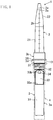
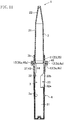
FIG. 2 is a longitudinal sectional view of the urine sampling container with the cover tube. -
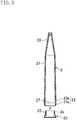
FIG. 3 is a longitudinal sectional view of a storage tube. -
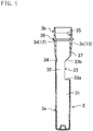
FIG. 4 is a longitudinal sectional view of a urine collection tube. -
FIG. 5 is a longitudinal sectional view of the cover tube. -
FIG. 6 is an enlarged sectional view of a main part of the urine sampling container. -
FIG. 7 is a plan view of the cover tube. -
FIG. 8 is a front view of the cover tube. -
FIG. 9 is a graph showing a temperature change range of a thermochromism material. -
FIG. 10 is a front view of the urine sampling container without the cover tube according to the second embodiment of the present invention. -
FIG. 11 is a longitudinal sectional view of the urine sampling container with the cover tube. -
FIG. 12 is a longitudinal sectional view of the storage tube. -
FIG. 13 is a longitudinal sectional view of the urine collection tube. -
FIG. 14 is a longitudinal sectional view of the cover tube. -
FIG. 15 is an enlarged sectional view of a main part of the urine sampling container. -
FIG. 16 is a plan view of the cover tube. -
FIG. 17 is a front view of the cover tube. -
FIG. 18 is a partially enlarged view ofFIG. 16 . - Embodiments of the present invention will be described in detail below with reference to the drawings.
- The first embodiment of the present invention will be described.
- A
urine sampling container 1 illustrated inFIGS. 1 and2 is a container for collecting urine at the time of a urinalysis conducted at a hospital or the like. - The
urine sampling container 1 includes astorage tube 2 for storing collected urine, aurine collection tube 3 for urine collection and measurement, and acover tube 4 detachably attached to theurine collection tube 3. - As illustrated in
FIG. 3 , thestorage tube 2 is formed as an elongated tubular body where one end thereof is closed and the other end is opened. Thestorage tube 2 is formed from a transparent material such as a synthetic resin. Note that the material of thestorage tube 2 is not limited to a transparent material, and may be formed from various materials such as a colored translucent material. - The
storage tube 2 includes amain body 21, occupying substantially a half of the entirety, in the lower side ofFIG. 3 , and a taperedsection 22, occupying substantially a half of the entirety, in the upper side ofFIG. 3 . Thestorage tube 2 is configured as a Spitz tube having an outer diameter and a length applicable to a urinalysis device. - The
main body 21 of thestorage tube 2 is formed in a tapered shape slightly thinner toward the taperedsection 22, and includes an opening end having an outer peripheral surface having a circumferential raisedsection 23 constituting aholding mechanism 11 for keeping thestorage tube 2 attached to theurine collection tube 3. The circumferential raisedsection 23 includes a first circumferential raisedsection 23a and a second circumferential raisedsection 23b. The taperedsection 22 of thestorage tube 2 is continuous with themain body 21 and formed in a tapered shape narrower toward the closed end. The taperedsection 22 of thestorage tube 2 has a larger taper angle than themain body 21. - The tapered
section 22 of thestorage tube 2 includes a tip end having a firstmarked line 2a and a secondmarked line 2a. The firstmarked line 2a and the secondmarked line 2a indicates the amount of residual urine; are used to centrifuge collected urine, discard a supernatant, and collect a sample for a urine sediment test (15 µl; microliter); and are set to display the storage amounts of 0.1 ml (milliliter) and 0.2 ml (milliliter), respectively. - The
storage tube 2 is labeled withurine collection scales 2b indicating the urine collection amount. The urine collection scales 2b are attached in the longitudinal direction of thestorage tube 2 so that the urine collection amount can be specified. - Note that the
urine sampling container 1 includes acap 25 for thestorage tube 2. Thecap 25 is fitted into themain body 21 of thestorage tube 2 and completely closes thestorage tube 2. - As illustrated in
FIG. 4 , theurine collection tube 3 is formed as an elongated tubular body where one end thereof is closed and the other end is opened. Theurine collection tube 3 is made of a synthetic resin thermochromism material. A thermochromism material is, for example, a material that reversibly changes between a color developing (colored) state and a non-color developing (non-colored) state. Examples of the color developing state include a pink color, a red color, an orange color, a blue color, a green color, and a black color. An example of the non-color developing state includes a light white color. - The discoloration temperature range of the thermochromism material can be selected within the range of, for example, -5°C to +55°C in an appropriate manner. In this embodiment, as illustrated in
FIG. 9 , when the temperature approaches a first temperature close to a human body temperature (approximately 35°C), the state turns to the non-color developing state. When the temperature approaches a second temperature (approximately 25°C) lower than the first temperature, the state turns to the color developing state. Note that inFIG. 9 , the mark "◆" represents discoloration appearing when the temperature increases from 20°C to 40°C. The mark "□" represents discoloration appearing when the temperature decreases from 40°C to 20°C. - As described above, the
urine collection tube 3 is made of a discoloration material that is in a colored state at an ordinary temperature (the second temperature) and changes to a non-color developing state when the temperature increase from the second temperature to the first temperature due to the temperature of the collected urine. Note that, in contrast, theurine collection tube 3 may be made of a discoloration material that is in a non-coloring state at the second temperature and changes from the non-coloring state to a coloring state when the temperature changes from the second temperature to the first temperature. - The thermochromism material can be, for example, a transparent synthetic resin kneaded with a thermochromism ink powder (microcapsule). This thermochromism ink powder does not contain harmful substances such as heavy metals (arsenic, lead, cadmium, mercury, selenium, antimony, chromium, barium, etc.).
- The
urine collection tube 3 includes amain body 3a and alarge diameter section 3b formed at the opening end. Themain body 3a includes ameasurement section 31, occupying substantially a half of the entirety, in the lower half ofFIG. 4 , and aurine collection section 32, occupying substantially a half of the entirety, in the upper half ofFIG. 4 . Themeasurement section 31 includes one end blocked, and measures urine necessary for the urinalysis. For example, themeasurement section 31 of theurine collection tube 3 has a storage volume of 10ml (milliliter). Note that the storage volume of themeasurement section 31 may be 15 ml (milliliter) or 20 ml (milliliter). In short, the storage volume of themeasurement section 31 may be 10 ml (milliliter) or more depending on a requirement for inspection or the like. Conversely, the storage volume of themeasurement section 31 may be less than 10 ml (milliliter). - The
urine collection section 32 of theurine collection tube 3 is formed as a tubular body where one end is continuous with themeasurement section 31 and the other end is opened. Theurine collection section 32 includes aurine collection port 33 and anauxiliary port 34. Theurine collection port 33 is an opening into which the urine is injected at the time of collecting the urine, and penetrates from the outer peripheral surface to the inner peripheral surface of theurine collection tube 3. Theurine collection port 33 is formed by cutting out an over-half part of theurine collection tube 3 in the circumferential direction. - One end of the
urine collecting port 33 closer to themeasurement section 31 is formed on anorthogonal surface 33a that coincides with the radial direction of theurine collection tube 3, and the other end is formed on aninclined surface 33b that is inclined toward the opening end. Then, themeasurement section 31 is from theorthogonal surface 33a of theurine collection port 33 to the closed end of theurine collection tube 3. - The
auxiliary port 34 penetrates from the outer peripheral surface opposite to theurine collection port 33 to the inner peripheral surface of theurine collection tube 3. Note the number of theauxiliary ports 34 may be two or more. Theauxiliary port 34 is formed to operate an air ventilation at the time of urine collection to facilitate the urine collection, and to prevent deformation at the time of molding. - The
large diameter section 3b is continuous with the opening end of theurine collection section 32, and is larger than the outer diameter of theurine collection section 32, such that the opening end of thestorage tube 2 is freely inserted thereto. - As illustrated in
FIG. 6 which is an enlarged sectional view of a main part of theurine sampling container 1, thelarge diameter section 3b has the inner peripheral surface provided with acircumferential groove 35 engaged with the first circumferential raisedsection 23a and the second circumferential raisedsection 23b of the circumferential raisedsection 23 of thestorage tube 2. Thecircumferential groove 35 includes afirst shoulder 35a abutting and engaging with the first circumferential raisedsection 23a, located on the open end side of thestorage tube 2, from the open end side of thestorage tube 2; and asecond shoulder 35b abutting and engaging with the second circumferential raisedsection 23b, located closer to the closed end side of thestorage tube 2 than the first circumferential raisedsection 23a, from the closed end side of thestorage tube 2, and constitutes the holdingmechanism 11 together with the circumferential raisedsection 23. The holdingmechanism 11 is formed at a position displaced from ajoint section 14 at which theurine collection tube 3 and thecover tube 4 overlap to be integrated together. - The circumferential raised
section 23 of thestorage tube 2 and thecircumferential groove 35 of theurine collection tube 3 make thestorage tube 2 and theurine collection tube 3 attachable and detachable. The circumferential raisedsection 23 of thestorage tube 2 and thecircumferential groove 35 of theurine collection tube 3 enables insertion and removal between thestorage tube 2 and theurine collection tube 3 without a relative rotation to allow thestorage tube 2 and theurine collection tube 3 to be attachable and detachable. - An end surface of the
large diameter section 3b closer theurine collection section 32 is formed as astep surface 3d next to themain body 3a, and thestep surface 3d is formed in an orthogonal plane coincident with the radial direction of theurine collection tube 3. Thelarge diameter section 3b has an outer peripheral end portion integrated with aflange section 36 constituting aretaining mechanism 15. Theflange section 36 is formed so as to be inserted into the end portion of thecover tube 4, and theflange section 36 includes a lower surface, which is thestep surface 3d. - A fixing
screw 37 fixing thecover tube 4 is formed between the opening end and theurine collection port 33 which is a part of the outer peripheral surface of themain body 3a of theurine collection tube 3. The fixingscrew 37 is configured so that thecover tube 4 is mounted in a state in which theurine collection tube 3 is inserted into thecover tube 4. - As illustrated in
FIG. 5 , thecover tube 4 is formed as an elongated tubular body where one end thereof is closed and the other end is opened. Thecover tube 4 is formed from a colored material such as a synthetic resin. Note that the material of thecover tube 4 is not limited to a colored material, and may be formed from other various materials. - The
cover tube 4 is formed slightly larger in diameter than theurine collection tube 3 so as to enablecollection tube 3 to engage therewith and be inserted and removed therefrom. - The
cover tube 4 has a length that allows the entirety of thebody portion 3a of theurine collection tube 3 to be inserted thereto when theurine collecting port 33 is closed. Thecover tube 4 includes amain body 41 closed at one end and opened at the other end and closing theurine collecting port 33 and alarge diameter section 42 formed at the opening end of themain body 41. Thelarge diameter section 42 is formed so as to be engaged with theurine collection tube 3 at thejoint section 14. On the inner peripheral surface of thelarge diameter section 42, a fixingscrew 43 screwed into the fixingscrew 37 of theurine collection tube 3 is formed. - Between the
urine collection tube 3 and thecover tube 4, provided are the retainingmechanism 15, an endsurface sealing unit 12 and a sidesurface sealing unit 13. - The retaining
mechanism 15 is provided near the opening ends of theurine collection tube 3 and thecover tube 4 to prevent thecover tube 4 from being disengaged from theurine collection tube 3 in a state in which theurine collection tube 3 is inserted into and fitted with thecover tube 4. The retainingmechanism 15 includes theflange section 36 formed on the entire periphery of the outer peripheral surface of theurine collection tube 3, and astopper tube 44 formed on thecover tube 4 allowing an insertion of theflange section 36 of theurine collection tube 3. On the inner peripheral surface of thestopper tube 44, a stopper protrusion (undercut section) 45 protruding inward in the radial direction so as to be engaged with theflange section 36 is formed at each two positions opposed to each other. The inner peripheral surface of thestopper protrusion 45 is formed as aninclined surface 45a of which the amount of protrusion increases from the opening end of thestopper tube 44 toward the back thereof. Further, thestopper tube 44 has aslit 44a positioned radially outward of theflange section 36, and theflange section 36 is positioned within theslit 44a. - In the
retaining mechanism 15, as thecover tube 4 of the imaginary line inFIG. 1 is fastened to theurine collection tube 3 with the fixing screws 37, 43, theflange section 36 moves into thestopper tube 44. When theflange 36 passes over and engages with thestopper protrusion 45, thecover tube 4 is not removed from theurine collection tube 3 even if thecover tube 4 is turned in the reverse direction. - The end
surface sealing unit 12 seals a portion between the opening of thecover tube 4 and theurine collection tube 3, and includes anend surface 4a on the lower side of the slit of thecover tube 4 and anend surface 3d of theflange section 36 of theurine collection tube 3. That is, as illustrated inFIG. 6 , the endsurface sealing unit 12 is configured so that, when thecover tube 4 is fastened to theurine collection tube 3, theend surface 4a of the slit of thecover tube 4 comes into close contact with theend surface 3d of the flange section of theurine collection tube 3. - The side
surface sealing unit 13 seals a portion between the opening end of thecover tube 4 and the opening end of theurine collection tube 3 at the side surface, and includes a slidingsurface 4b formed on thecover tube 4, and a slidingsurface 3e formed on theurine collection tube 3. The slidingsurface 4b of thecover tube 4 is a part of the inner peripheral surface of themain body 41 of thecover tube 4, and is formed at the peripheral edge of the opening end. The slidingsurface 3e of theurine collection tube 3 is a part of the outer peripheral surface of themain body 3a in theurine collection tube 3, and is formed between the opening end and the fixingscrew 37. As illustrated inFIG. 6 , the slidingsurface 4b of thecover tube 4 and the slidingsurface 3e of theurine collection tube 3 are configured to be in close contact with each other when theurine collection tube 3 is inserted into thecover tube 4. The portion at which thecover tube 4 and theurine collection tube 3 overlap one another and the portion including the fixing screws 37, 43 constitute thejoint section 14. - The
storage tube 2 includes a fixing raisedsection 27 for fixing thecap 25. The fixing raisedsection 27 is annularly formed on the inner peripheral surface of the opening end of themain body 21 of thestorage tube 2. On the other hand, thecap 25 includes afitting section 2e to be fitted into themain body 21 of thestorage tube 2, and a ring-shaped raised section 2f is formed on the outer peripheral face of thefitting section 2e. When thecap 25 is fitted into thestorage tube 2, and the raised section 2f of thecap 25 passes over the fixing raisedsection 27, the fixing raisedsection 27 generates a "clink" sound that indicates a completion of the fitting. - Next, a procedure for using the
urine sampling container 1 will be described. - First, in an unused state before urine collection, the
urine sampling container 1 is placed in a packaging bag. At this time, the opening end of thestorage tube 2 is inserted into the opening end of theurine collection tube 3 so that thestorage tube 2 and theurine collection tube 3 are coupled together. In addition, as shown by the imaginary lines inFIG. 1 , theurine collection tube 3 is merely lightly inserted into thecover tube 4 so that thecover tube 4 is easily disengaged from theurine collection tube 3. - Next, at the time of urine collection, the examinee takes out the
urine sampling container 1 from the packaging bag, and removes thecover tube 4 from theurine collection tube 3. Theurine collection tube 3 is lightly inserted in thecover tube 4, and thus thecover tube 4 is easily removed from theurine collection tube 3. Then, in a state in which theurine collection tube 3 is attached to thestorage tube 2, the examinee grips thestorage tube 2 with theurine collection tube 3 oriented downward. Next, when the examinee applies urine to theurine collection port 33, the urine flows from theurine collection port 33 into theurine collection tube 3, and accumulates in themeasurement section 31. Then, the collection of urine is completed. When a predetermined amount (for example, 10 ml) of urine is injected into themeasurement section 31 in this urine collection, the urine leaks from theurine collection port 33 to the outside of theurine collection tube 3. Thus, an necessary amount for urinalysis is reliably collected, and no redundant urine is collected. At the time of urine collection, the difference in the wall thickness between thestorage tube 2 and theurine collection tube 3 is small, and the difference in the rigidity therebetween is also small, such that thestorage tube 2 and theurine collection tube 3 are not easily separated. - Upon completion of this urine collection, the
urine sampling container 1 is transferred to an laboratory or the like. - During the transportation, as illustrated in
FIG. 2 , theurine collection tube 3 oriented downward is inserted into thecover tube 4 so that theurine collection tube 3, which is a dirty part, is covered. At this time, when theurine collection tube 3 is inserted into thecover tube 4, theurine collection port 33 is closed by thecover tube 4. Next, theurine collection tube 3 is turned with respect to thecover tube 4 to tighten the fixing screws 37, 43 to allow theflange section 36 to pass over and engage with thestopper protrusion 45. At this time, the fixing screws 37, 43 join and fix thecover tube 4 and theurine collection tube 3, and, as illustrated inFIGS. 2 and6 , theflange section 36 and thestopper protrusion 45 prevent the fixing screws 37, 43 from turning in the reverse direction. Thus, thecover tube 4 and theurine collection tube 3 cannot be disengaged from each other even if the cover tube is turned in the reverse direction. - When the
cover tube 4 and theurine collection tube 3 are joined together as illustrated inFIGS. 2 and6 , the openingend surface 4a of thecover tube 4 comes into close contact with thestep surface 3d of thelarge diameter section 3b of theurine collection tube 3, and the portion between thecover tube 4 and theurine collection tube 3 is sealed (the end surface sealing unit 12). Further, when theurine collection tube 3 is inserted into thecover tube 4, the slidingsurface 4b of thecover tube 4 and the slidingsurface 3e of theurine collection tube 3 come into close contact with each other, and the portion between thecover tube 4 and theurine collection tube 3 is sealed (the side surface sealing unit 13). Thus, the leakage of urine is prevented. - Next, the
urine sampling container 1 inverted upside down is transferred to the laboratory or the like while thestorage tube 2 oriented downward is inserted in the container stand or the like. At this time, when theurine collection tube 3 is turned upside down, the urine flows into thestorage tube 2, and the urine is stored in thestorage tube 2. - Then, in the laboratory or the like, when the examiner bends the
storage tube 2 in an "L" shape at the joint section with respect to theurine collection tube 3 and thecover tube 4 integrated together, the holdingmechanism 11 is disengaged. Unlike the time of urine collection, the rigidity of theurine collection tube 3 and thecover tube 4 integrated together is larger than that of thestorage tube 2, and thestorage tube 2 is easily deformed. Thus, thestorage tube 2 is disengaged from theurine collection tube 3 and thecover tube 4. Then, only thestorage tube 2 storing the urine is set in the examination device. - This embodiment may be as follows. After urine collection is finished, the
urine collection tube 3 oriented downward may be inserted into thecover tube 4. Then, after theurine collection port 33 is closed by thecover tube 4, theurine sampling container 1 is inverted upside down, and then the urine is stored in thestorage tube 2. Further, after thestorage tube 2 is removed from theurine collection tube 3 and thecover tube 4, thecap 25 is fitted into the opening end of thestorage tube 2. Then, thestorage tube 2 is transferred to the laboratory or the like and set in the examination device. - In the urinalysis, the
storage tube 2 is installed in a centrifugal separator, and a liquid component and a solid component are separated. Then, decantation is performed to discard the liquid component of a supernatant. Then, thestorage tube 2 is inverted to remove the liquid component, and a precipitate remaining in the storage tube is used for an examination. - In this embodiment, at the time of urine collection, the
cover tube 4 is not attached on theurine sampling container 1, and thestorage tube 2 and theurine collection tube 3 are joined by the holdingmechanism 11 including the circumferential raisedsection 23 and thecircumferential groove 35. At this time, the difference in the wall thickness between thestorage tube 2 and theurine collection tube 3 is small (or there is no difference in the wall thickness), and thus the difference in the rigidity between thestorage tube 2 and theurine collection tube 3 is small, such that the portion coupled by the holdingmechanism 11 is less likely to be deformed. On the other hand, when thecover tube 4 is attached to theurine collection tube 3 after the urine collection, theurine collection tube 3 and thecover tube 4 overlap and are integrated with each other through the fixing screws 37, 43 so that the wall thickness of thejoint section 14 is larger than that of thestorage tube 2. Thus, the rigidity of theurine collection tube 3 and thecover tube 4 integrated together is larger than that of thestorage tube 2, and thestorage tube 2 is easily deformed at the portion coupled by the holdingmechanism 11. - According to this embodiment, at the time of urine collection, the difference in the rigidity between the
storage tube 2 and theurine collection tube 3 is small, and the coupling portion between thestorage tube 2 and theurine collection tube 3 is less likely to be deformed. Thus, thestorage tube 2 and theurine collection tube 3 are reliably joined and not easily disengaged. On the other hand, at the time of examination, the rigidity of theurine collection tube 3 and thecover tube 4 integrated together is larger than that of thestorage tube 2, and thestorage tube 2 is easily deformed at the coupling portion. Thus, the examiner can easily bend and disengage thestorage tube 2 into the "L" shape at the coupling portion with respect to theurine collection tube 3 and thecover tube 4 integrated together. As such, this embodiment provides the structure in which the urine collection tube and the storage tube are securely coupled at the time of urine collection, and the storage tube is easily disengaged from the urine collection tube at the time of examination. - According to this embodiment, the
cover tube 4 is not removed from theurine collection tube 3 only by inserting theflange section 36 into thestopper tube 44 and engaging theflange section 36 with thestopper protrusion 45. Thus, the retainingmechanism 15 having a simple configuration can be achieved. - According to this embodiment, when the circumferential raised
section 23 formed on the outer peripheral surface of thestorage tube 2 and the circumferential recessedsection 35 formed on the inner peripheral surface of theurine collection tube 3 are fitted with each other, thefirst shoulder 35a comes into contact with the first circumferential raisedsection 23a from the opening end of thestorage tube 2, and thesecond shoulder 35b comes into contact with the second circumferential raisedsection 23b from the closed end of thestorage tube 2, so that thestorage tube 2 is kept inserted in theurine collection tube 3. Thus, the holding mechanism including the circumferential raisedsection 23 and the circumferential recessedsection 35 can be achieved with a simple configuration. In addition, the set of the first circumferential raisedsection 23a and thefirst shoulder 35a is located closer to the opening end of thestorage tube 2, and the set of the second circumferential raisedsection 23b and thesecond shoulder 35b is located closer to the closed end of thestorage tube 2 so that these set are located apart from each other. Thus, thestorage tube 2 is inserted in and stably held in theurine collection tube 3. - According to this embodiment, when urine is applied to the
urine collection tube 3 at the time of urine collection, theurine collection tube 3 having had a low temperature (a room temperature) is discolored due to the influence of a urine temperature (approximately a body temperature). In some conventional cases, it was difficult to determine a completion of urine collection in an environment such as dark surroundings. In contrast, in this embodiment, theurine collection tube 3 is discolored so that the examinee can surely recognize a completion of urine collection. - The second embodiment of the present invention illustrated in
FIGS. 10 to 18 will be described. - The second embodiment of the present invention is different from the first embodiment in the configuration of the
retaining mechanism 15. - In this embodiment, as illustrated in
FIGS. 13 to 15 , a firstanti-rotation ring 38 is formed at the position of thestep surface 3d in thelarge diameter section 3b of theurine collection tube 3, and a secondanti-rotation ring 46 is formed on thelarge diameter section 42 of thecover tube 4. The firstanti-rotation ring 38 and the secondanti-rotation ring 46 are formed to engage with each other. - As illustrated in
FIGS. 15 to 18 , a first stopper raisedsection 38a is formed on the outer peripheral surface of the firstanti-rotation ring 38 of theurine collection tube 3, and a second stopper raisedsection 46a is formed on the inner peripheral surface of the secondanti-rotation ring 46 of thecover tube 4. The first stopper raisedsection 38a and the second stopper raisedsection 46a are engaged with each other in a state in which theurine collection tube 3 is screwed into thecover tube 4, and prohibit a rotation in the direction of loosening the fixing screws 37 and 43. The first stopper raisedsection 38a and the second stopper raisedsection 46a constitute theretaining mechanism 15. - As a precondition, the retaining
mechanism 15 has the configuration in which theurine collection tube 3 is screwed into thecover tube 4 for joint. In this configuration, when the first stopper raisedsection 38a and the second stopper raisedsection 46a are engaged with each other as illustrated inFIG. 15 , thecover tube 4 is not removed from theurine collection tube 3 even if thecover tube 4 is turned in the reverse direction. - The end
surface sealing unit 12 includes the openingend surface 4a of thecover tube 4 and thestep surface 3d of theurine collection tube 3 to seal the portion between the opening end of thecover tube 4 and theurine collection tube 3. The configuration is substantially the same as that of the first embodiment. That is, as illustrated in the enlarged view ofFIG. 15 , the endsurface sealing unit 12 is formed such that, when thecover tube 4 is screwed into theurine collection tube 3, the openingend surface 4a of thelarge diameter section 42 of thecover tube 4 comes into close contact with thestep surface 3d of thediameter section 3b. - The other configurations are the same as those in the first embodiment.
- Also in this embodiment, at the time of urine collection, the difference in the rigidity between the
storage tube 2 and theurine collection tube 3 is small, and the coupling portion between thestorage tube 2 and theurine collection tube 3 is less likely to be deformed. Thus, thestorage tube 2 and theurine collection tube 3 are reliably joined and not easily disengaged. On the other hand, at the time of examination, the rigidity of theurine collection tube 3 and thecover tube 4 integrated together is larger than that of thestorage tube 2, and thestorage tube 2 is easily deformed at the coupling portion. Thus, the examiner can easily bend and disengage thestorage tube 2 into the "L" shape at the coupling portion with respect to theurine collection tube 3 and thecover tube 4 integrated together. As such, this embodiment provides the structure in which the urine collection tube and the storage tube are securely coupled at the time of urine collection, and the storage tube is easily disengaged from the urine collection tube at the time of examination. - According to this embodiment, when the
urine collection tube 3 is screwed to thecover tube 4, the first stopper raisedsection 38a and the second stopper raisedsection 46a are engaged and prohibited from turning in the reverse direction, and thestorage tube 2 is not removed from theurine collection tube 3. Thus, the retainingmechanism 15 can be achieved with a simple structure. - The other same advantages as those of the first embodiment can be achieved.
- The above embodiments may be configured as follows.
- In the above embodiments, the
urine collection tube 3 is made of a discoloration material, but in the present invention, theurine collection tube 3 does not necessarily have discoloration properties. - The retaining mechanism described in each of the above embodiments is an example of the configuration in which the
cover tube 4 is not removed from theurine collection tube 3, but any other configurations may be adopted. - The holding
mechanism 11 described in the above embodiments is not limited to the configuration in which the circumferential raisedsection 23 and the circumferential recessedsection 35 are engaged with each other, and may adopt other configurations such as a screw connection. Still in that case, the rigidity is large when theurine collection tube 3 and thecover tube 4 are integrated together to increase, and thus thestorage tube 2 can be easily removed. - In the present invention, as long as the
retaining mechanism 15 is provided, the other specific configurations of thestorage tube 2, theurine collection tube 3, and thecover tube 4 are not limited to those of the above embodiment, and can be changed if necessary. - Note that the above embodiments are essentially preferred examples, and not intended to limit the scope application, or usage of the present invention.
- As described above, the present invention is useful for a urine sampling container for urinalysis.
-
- 1
- Urine Sampling Container
- 2
- Storage Tube
- 3
- Urine Collection Tube
- 4
- Cover
- 11
- Holding Mechanism
- 15
- Retaining Mechanism
- 23
- Circumferential Raised Section
- 23a
- First Circumferential Raised Section
- 23b
- Second Circumferential Raised Section
- 33
- Urine Collection Port
- 35
- Circumferential Recessed Section
- 35a
- First Shoulder
- 35b
- Second Shoulder
- 36
- Flange Section
- 38a
- First Stopper Raised Section
- 44
- Stopper Tube
- 44a
- Slit
- 45
- Stopper Protrusion
- 45a
- Inclined Surface
- 46a
- Second Stopper Raised Section
Claims (10)
- A urine sampling container (1), comprising:a storage tube (2) formed as an elongated tube and storing urine, where one end of the storage tube (2) is a closed end and the other end of the storage tube (2) is an opening end;a urine collection tube (3) formed as an elongated tube and including a side surface having a urine collection port (33), where one end of the urine collection tube (3) is a closed end and the other end of the urine collection tube (3) is an opening end freely attachable to and detachable from the opening end of the storage tube (2);a cover tube (4) formed as an elongated tube, formed so that the urine collection tube (3) can be inserted to and removed from the cover tube (4), and covering the urine collection port (33), where one end of the cover tube (4) is a closed end and the other end of the cover tube (4) is an opening end;wherein the urine collection tube (3) is screwed in the cover tube (4) in a state in which the urine collection tube (3) is inserted in the cover tube (4);characterized in thata retaining mechanism (15) provided near the opening ends of the urine collection tube (3) and the cover tube (4) to prevent the cover tube (4) from being removed from the urine collection tube (3) in a state in which the urine collection tube (3) is inserted, screwed and fitted in the cover tube (4).
- The urine sampling container (1) of claim 1, wherein
the retaining mechanism (15) includesa flange section (36) formed on the urine collection tube (3) anda stopper tube (44) formed on the cover tube (4) allowing an insertion of the flange section (36) of the urine collection tube (3), andon an inner peripheral surface of the stopper tube (44), a stopper protrusion (45) to be engaged with the flange section (36) is formed. - The urine sampling container (1) of claim 2, wherein
an inner peripheral surface of the stopper protrusion (45) is formed as an inclined surface of which the amount of protrusion increases from the opening end of the stopper tube (44) toward the back thereof. - The urine sampling container (1) of claim 3, wherein
the stopper tube (44) has a slit positioned radially outward of the flange section (36). - The urine sampling container (1) of claim 1, wherein
the retaining mechanism (15) includesa first stopper raised section (38a) formed on the urine collection tube (3) anda second stopper raised section (46a) formed on the cover tube (4), andthe first stopper raised section (38a) and the second stopper raised section (46a) are configured to prohibit a rotation in a direction of loosening a screw in a state in which the urine collection tube (3) is screwed into the cover tube (4). - The urine sampling container (1) of any one of claims 1 to 5, wherein
a holding mechanism (11) for keeping the storage tube (2) inserted in the urine collection tube (3) is formed on an outer peripheral surface of the storage tube (2) and an inner peripheral surface of the urine collection tube (3), at a position displaced from a joint section at which the urine collection tube (3) and the cover tube (4) overlap to be integrated together, and
the holding mechanism (11) includesa circumferential raised section (23) formed on the outer peripheral surface of the storage tube (2) anda circumferential recessed section (35) formed on the inner peripheral surface of the urine collection tube (3) and fitted with the circumferential raised section (23). - The urine sampling container (1) of claim 6, wherein
the circumferential raised section (23) of the holding mechanism (11) includesa first circumferential raised section (23a) located closer to the opening end of the storage tube (2) anda second circumferential raised section (23b) located closer to the closed end than the first circumferential raised section (23a), andthe circumferential recessed section (35) of the holding mechanism (11) includesa first shoulder (35a) coming into contact with the first circumferential raised section (23a) from the opening end of the storage tube (2) anda second shoulder (35b) coming into contact with the second circumferential raised section (23b) from the closed end of the storage tube (2). - The urine sampling container (1) of any one of claims 1 to 7, wherein
the urine collection tube (3) is made of a discoloration material exhibiting a respective different color at a first temperature corresponding to a human body temperature and at a second temperature lower than the first temperature. - The urine sampling container (1) of claim 8, wherein
the urine collection tube (3) is made of a material that is in a non-coloring state at the second temperature and changes from the non-coloring state to a coloring state when the temperature changes from the second temperature to the first temperature. - The urine sampling container (1) of claim 8, wherein
the urine collection tube (3) is made of a material that is in a coloring state at the second temperature and changes from the coloring state to a non-coloring state when the temperature changes from the second temperature to the first temperature.
Applications Claiming Priority (2)
| Application Number | Priority Date | Filing Date | Title |
|---|---|---|---|
| JP2015210139A JP6708390B2 (en) | 2015-10-26 | 2015-10-26 | Urine collection container |
| PCT/JP2016/002232 WO2017072983A1 (en) | 2015-10-26 | 2016-04-28 | Urine sampling container |
Publications (3)
| Publication Number | Publication Date |
|---|---|
| EP3358335A1 EP3358335A1 (en) | 2018-08-08 |
| EP3358335A4 EP3358335A4 (en) | 2018-11-14 |
| EP3358335B1 true EP3358335B1 (en) | 2019-11-06 |
Family
ID=58631490
Family Applications (1)
| Application Number | Title | Priority Date | Filing Date |
|---|---|---|---|
| EP16859224.4A Active EP3358335B1 (en) | 2015-10-26 | 2016-04-28 | Urine sampling container |
Country Status (4)
| Country | Link |
|---|---|
| US (1) | US10882043B2 (en) |
| EP (1) | EP3358335B1 (en) |
| JP (1) | JP6708390B2 (en) |
| WO (1) | WO2017072983A1 (en) |
Families Citing this family (1)
| Publication number | Priority date | Publication date | Assignee | Title |
|---|---|---|---|---|
| JP7435081B2 (en) * | 2020-03-16 | 2024-02-21 | 住友ベークライト株式会社 | Storage containers for physics and chemistry |
Family Cites Families (8)
| Publication number | Priority date | Publication date | Assignee | Title |
|---|---|---|---|---|
| US4832046A (en) | 1987-06-24 | 1989-05-23 | Medical Implements, Inc. | Urine specimen collectors and method of detecting spurious urine specimens |
| WO1999032871A1 (en) * | 1997-12-19 | 1999-07-01 | Itochu Corporation | Container for urine test |
| JP4158094B2 (en) * | 2003-01-15 | 2008-10-01 | 株式会社クニムネ | Urine sample collection and storage equipment |
| EP1681547A1 (en) * | 2003-11-07 | 2006-07-19 | Universal Bio Research Co., Ltd. | Container for packing reagent |
| US8597593B2 (en) * | 2006-12-07 | 2013-12-03 | Brand Gmbh + Co Kg | Bottle top dispenser for handling liquids |
| JP4953980B2 (en) * | 2007-08-20 | 2012-06-13 | 株式会社アトレータ | Urine collection container |
| JP5802899B2 (en) * | 2011-08-11 | 2015-11-04 | 株式会社アトレータ | Urine collection container |
| JP2015049202A (en) * | 2013-09-04 | 2015-03-16 | 禮子 辻 | Container for urine collection |
-
2015
- 2015-10-26 JP JP2015210139A patent/JP6708390B2/en active Active
-
2016
- 2016-04-28 EP EP16859224.4A patent/EP3358335B1/en active Active
- 2016-04-28 WO PCT/JP2016/002232 patent/WO2017072983A1/en not_active Ceased
- 2016-04-28 US US15/770,259 patent/US10882043B2/en active Active
Non-Patent Citations (1)
| Title |
|---|
| None * |
Also Published As
| Publication number | Publication date |
|---|---|
| EP3358335A4 (en) | 2018-11-14 |
| WO2017072983A1 (en) | 2017-05-04 |
| EP3358335A1 (en) | 2018-08-08 |
| JP6708390B2 (en) | 2020-06-10 |
| JP2017083238A (en) | 2017-05-18 |
| US10882043B2 (en) | 2021-01-05 |
| US20180311667A1 (en) | 2018-11-01 |
Similar Documents
| Publication | Publication Date | Title |
|---|---|---|
| US9149258B2 (en) | Collection device with double outputs and method of using the same | |
| ES2641501T3 (en) | Extraction module, especially for blood samples | |
| EP0820812A2 (en) | A specimen collection assembly | |
| AU8319998A (en) | Ball and socket closure for specimen collection container incorporating a resilient elastomeric seal | |
| EP0901827B1 (en) | Ball and socket closure for specimen collection container | |
| US11338088B2 (en) | Venting safety closure | |
| AU8320298A (en) | Ball and socket closure for specimen collection container incorporating a dimple locking mechanism | |
| US5224632A (en) | Measuring cap | |
| AU8317698A (en) | Ball and socket closure for specimen collection container incorporating a septum | |
| KR102111659B1 (en) | specimen container | |
| CN105324315B (en) | Lidded container | |
| CA2888947A1 (en) | Vessel | |
| US6955099B2 (en) | Spill proof liquid sample cup | |
| CN110946624B (en) | A container system and method for releasably storing a substance | |
| CN208607048U (en) | Saliva collection device | |
| US10882043B2 (en) | Urine sampling container | |
| ITUB20154921A1 (en) | Closing by device for the processing of biological samples | |
| JP4953980B2 (en) | Urine collection container | |
| JP5802899B2 (en) | Urine collection container | |
| US20060142669A1 (en) | Urine sampling container | |
| JP6643042B2 (en) | Urine collection container | |
| US9067203B2 (en) | Integrated specimen cup system for tamperproof sample testing and secure retention | |
| EP1063508A1 (en) | Container for urine test | |
| US10399743B1 (en) | Container with silicone insert compartment and segregated storage region | |
| CA1058566A (en) | Specimen container |
Legal Events
| Date | Code | Title | Description |
|---|---|---|---|
| STAA | Information on the status of an ep patent application or granted ep patent |
Free format text: STATUS: THE INTERNATIONAL PUBLICATION HAS BEEN MADE |
|
| PUAI | Public reference made under article 153(3) epc to a published international application that has entered the european phase |
Free format text: ORIGINAL CODE: 0009012 |
|
| STAA | Information on the status of an ep patent application or granted ep patent |
Free format text: STATUS: REQUEST FOR EXAMINATION WAS MADE |
|
| 17P | Request for examination filed |
Effective date: 20180504 |
|
| AK | Designated contracting states |
Kind code of ref document: A1 Designated state(s): AL AT BE BG CH CY CZ DE DK EE ES FI FR GB GR HR HU IE IS IT LI LT LU LV MC MK MT NL NO PL PT RO RS SE SI SK SM TR |
|
| AX | Request for extension of the european patent |
Extension state: BA ME |
|
| A4 | Supplementary search report drawn up and despatched |
Effective date: 20181017 |
|
| RIC1 | Information provided on ipc code assigned before grant |
Ipc: G01N 33/48 20060101ALI20181011BHEP Ipc: A61B 10/00 20060101ALI20181011BHEP Ipc: G01N 1/10 20060101AFI20181011BHEP |
|
| DAV | Request for validation of the european patent (deleted) | ||
| DAX | Request for extension of the european patent (deleted) | ||
| GRAP | Despatch of communication of intention to grant a patent |
Free format text: ORIGINAL CODE: EPIDOSNIGR1 |
|
| STAA | Information on the status of an ep patent application or granted ep patent |
Free format text: STATUS: GRANT OF PATENT IS INTENDED |
|
| INTG | Intention to grant announced |
Effective date: 20190711 |
|
| GRAS | Grant fee paid |
Free format text: ORIGINAL CODE: EPIDOSNIGR3 |
|
| GRAA | (expected) grant |
Free format text: ORIGINAL CODE: 0009210 |
|
| STAA | Information on the status of an ep patent application or granted ep patent |
Free format text: STATUS: THE PATENT HAS BEEN GRANTED |
|
| AK | Designated contracting states |
Kind code of ref document: B1 Designated state(s): AL AT BE BG CH CY CZ DE DK EE ES FI FR GB GR HR HU IE IS IT LI LT LU LV MC MK MT NL NO PL PT RO RS SE SI SK SM TR |
|
| REG | Reference to a national code |
Ref country code: GB Ref legal event code: FG4D |
|
| REG | Reference to a national code |
Ref country code: CH Ref legal event code: EP Ref country code: AT Ref legal event code: REF Ref document number: 1199406 Country of ref document: AT Kind code of ref document: T Effective date: 20191115 |
|
| REG | Reference to a national code |
Ref country code: IE Ref legal event code: FG4D |
|
| REG | Reference to a national code |
Ref country code: DE Ref legal event code: R096 Ref document number: 602016024068 Country of ref document: DE |
|
| REG | Reference to a national code |
Ref country code: NL Ref legal event code: MP Effective date: 20191106 |
|
| REG | Reference to a national code |
Ref country code: LT Ref legal event code: MG4D |
|
| PG25 | Lapsed in a contracting state [announced via postgrant information from national office to epo] |
Ref country code: LT Free format text: LAPSE BECAUSE OF FAILURE TO SUBMIT A TRANSLATION OF THE DESCRIPTION OR TO PAY THE FEE WITHIN THE PRESCRIBED TIME-LIMIT Effective date: 20191106 Ref country code: LV Free format text: LAPSE BECAUSE OF FAILURE TO SUBMIT A TRANSLATION OF THE DESCRIPTION OR TO PAY THE FEE WITHIN THE PRESCRIBED TIME-LIMIT Effective date: 20191106 Ref country code: SE Free format text: LAPSE BECAUSE OF FAILURE TO SUBMIT A TRANSLATION OF THE DESCRIPTION OR TO PAY THE FEE WITHIN THE PRESCRIBED TIME-LIMIT Effective date: 20191106 Ref country code: NL Free format text: LAPSE BECAUSE OF FAILURE TO SUBMIT A TRANSLATION OF THE DESCRIPTION OR TO PAY THE FEE WITHIN THE PRESCRIBED TIME-LIMIT Effective date: 20191106 Ref country code: PT Free format text: LAPSE BECAUSE OF FAILURE TO SUBMIT A TRANSLATION OF THE DESCRIPTION OR TO PAY THE FEE WITHIN THE PRESCRIBED TIME-LIMIT Effective date: 20200306 Ref country code: NO Free format text: LAPSE BECAUSE OF FAILURE TO SUBMIT A TRANSLATION OF THE DESCRIPTION OR TO PAY THE FEE WITHIN THE PRESCRIBED TIME-LIMIT Effective date: 20200206 Ref country code: PL Free format text: LAPSE BECAUSE OF FAILURE TO SUBMIT A TRANSLATION OF THE DESCRIPTION OR TO PAY THE FEE WITHIN THE PRESCRIBED TIME-LIMIT Effective date: 20191106 Ref country code: GR Free format text: LAPSE BECAUSE OF FAILURE TO SUBMIT A TRANSLATION OF THE DESCRIPTION OR TO PAY THE FEE WITHIN THE PRESCRIBED TIME-LIMIT Effective date: 20200207 Ref country code: FI Free format text: LAPSE BECAUSE OF FAILURE TO SUBMIT A TRANSLATION OF THE DESCRIPTION OR TO PAY THE FEE WITHIN THE PRESCRIBED TIME-LIMIT Effective date: 20191106 Ref country code: BG Free format text: LAPSE BECAUSE OF FAILURE TO SUBMIT A TRANSLATION OF THE DESCRIPTION OR TO PAY THE FEE WITHIN THE PRESCRIBED TIME-LIMIT Effective date: 20200206 |
|
| PG25 | Lapsed in a contracting state [announced via postgrant information from national office to epo] |
Ref country code: RS Free format text: LAPSE BECAUSE OF FAILURE TO SUBMIT A TRANSLATION OF THE DESCRIPTION OR TO PAY THE FEE WITHIN THE PRESCRIBED TIME-LIMIT Effective date: 20191106 Ref country code: HR Free format text: LAPSE BECAUSE OF FAILURE TO SUBMIT A TRANSLATION OF THE DESCRIPTION OR TO PAY THE FEE WITHIN THE PRESCRIBED TIME-LIMIT Effective date: 20191106 Ref country code: IS Free format text: LAPSE BECAUSE OF FAILURE TO SUBMIT A TRANSLATION OF THE DESCRIPTION OR TO PAY THE FEE WITHIN THE PRESCRIBED TIME-LIMIT Effective date: 20200306 |
|
| PG25 | Lapsed in a contracting state [announced via postgrant information from national office to epo] |
Ref country code: AL Free format text: LAPSE BECAUSE OF FAILURE TO SUBMIT A TRANSLATION OF THE DESCRIPTION OR TO PAY THE FEE WITHIN THE PRESCRIBED TIME-LIMIT Effective date: 20191106 |
|
| PG25 | Lapsed in a contracting state [announced via postgrant information from national office to epo] |
Ref country code: DK Free format text: LAPSE BECAUSE OF FAILURE TO SUBMIT A TRANSLATION OF THE DESCRIPTION OR TO PAY THE FEE WITHIN THE PRESCRIBED TIME-LIMIT Effective date: 20191106 Ref country code: EE Free format text: LAPSE BECAUSE OF FAILURE TO SUBMIT A TRANSLATION OF THE DESCRIPTION OR TO PAY THE FEE WITHIN THE PRESCRIBED TIME-LIMIT Effective date: 20191106 Ref country code: RO Free format text: LAPSE BECAUSE OF FAILURE TO SUBMIT A TRANSLATION OF THE DESCRIPTION OR TO PAY THE FEE WITHIN THE PRESCRIBED TIME-LIMIT Effective date: 20191106 Ref country code: CZ Free format text: LAPSE BECAUSE OF FAILURE TO SUBMIT A TRANSLATION OF THE DESCRIPTION OR TO PAY THE FEE WITHIN THE PRESCRIBED TIME-LIMIT Effective date: 20191106 Ref country code: ES Free format text: LAPSE BECAUSE OF FAILURE TO SUBMIT A TRANSLATION OF THE DESCRIPTION OR TO PAY THE FEE WITHIN THE PRESCRIBED TIME-LIMIT Effective date: 20191106 |
|
| REG | Reference to a national code |
Ref country code: DE Ref legal event code: R097 Ref document number: 602016024068 Country of ref document: DE |
|
| REG | Reference to a national code |
Ref country code: AT Ref legal event code: MK05 Ref document number: 1199406 Country of ref document: AT Kind code of ref document: T Effective date: 20191106 |
|
| PG25 | Lapsed in a contracting state [announced via postgrant information from national office to epo] |
Ref country code: SK Free format text: LAPSE BECAUSE OF FAILURE TO SUBMIT A TRANSLATION OF THE DESCRIPTION OR TO PAY THE FEE WITHIN THE PRESCRIBED TIME-LIMIT Effective date: 20191106 Ref country code: SM Free format text: LAPSE BECAUSE OF FAILURE TO SUBMIT A TRANSLATION OF THE DESCRIPTION OR TO PAY THE FEE WITHIN THE PRESCRIBED TIME-LIMIT Effective date: 20191106 |
|
| PLBE | No opposition filed within time limit |
Free format text: ORIGINAL CODE: 0009261 |
|
| STAA | Information on the status of an ep patent application or granted ep patent |
Free format text: STATUS: NO OPPOSITION FILED WITHIN TIME LIMIT |
|
| 26N | No opposition filed |
Effective date: 20200807 |
|
| PG25 | Lapsed in a contracting state [announced via postgrant information from national office to epo] |
Ref country code: MC Free format text: LAPSE BECAUSE OF FAILURE TO SUBMIT A TRANSLATION OF THE DESCRIPTION OR TO PAY THE FEE WITHIN THE PRESCRIBED TIME-LIMIT Effective date: 20191106 Ref country code: SI Free format text: LAPSE BECAUSE OF FAILURE TO SUBMIT A TRANSLATION OF THE DESCRIPTION OR TO PAY THE FEE WITHIN THE PRESCRIBED TIME-LIMIT Effective date: 20191106 Ref country code: AT Free format text: LAPSE BECAUSE OF FAILURE TO SUBMIT A TRANSLATION OF THE DESCRIPTION OR TO PAY THE FEE WITHIN THE PRESCRIBED TIME-LIMIT Effective date: 20191106 |
|
| REG | Reference to a national code |
Ref country code: CH Ref legal event code: PL |
|
| PG25 | Lapsed in a contracting state [announced via postgrant information from national office to epo] |
Ref country code: LU Free format text: LAPSE BECAUSE OF NON-PAYMENT OF DUE FEES Effective date: 20200428 Ref country code: CH Free format text: LAPSE BECAUSE OF NON-PAYMENT OF DUE FEES Effective date: 20200430 Ref country code: IT Free format text: LAPSE BECAUSE OF FAILURE TO SUBMIT A TRANSLATION OF THE DESCRIPTION OR TO PAY THE FEE WITHIN THE PRESCRIBED TIME-LIMIT Effective date: 20191106 Ref country code: LI Free format text: LAPSE BECAUSE OF NON-PAYMENT OF DUE FEES Effective date: 20200430 |
|
| REG | Reference to a national code |
Ref country code: BE Ref legal event code: MM Effective date: 20200430 |
|
| PG25 | Lapsed in a contracting state [announced via postgrant information from national office to epo] |
Ref country code: BE Free format text: LAPSE BECAUSE OF NON-PAYMENT OF DUE FEES Effective date: 20200430 |
|
| PG25 | Lapsed in a contracting state [announced via postgrant information from national office to epo] |
Ref country code: IE Free format text: LAPSE BECAUSE OF NON-PAYMENT OF DUE FEES Effective date: 20200428 |
|
| PG25 | Lapsed in a contracting state [announced via postgrant information from national office to epo] |
Ref country code: TR Free format text: LAPSE BECAUSE OF FAILURE TO SUBMIT A TRANSLATION OF THE DESCRIPTION OR TO PAY THE FEE WITHIN THE PRESCRIBED TIME-LIMIT Effective date: 20191106 Ref country code: MT Free format text: LAPSE BECAUSE OF FAILURE TO SUBMIT A TRANSLATION OF THE DESCRIPTION OR TO PAY THE FEE WITHIN THE PRESCRIBED TIME-LIMIT Effective date: 20191106 Ref country code: CY Free format text: LAPSE BECAUSE OF FAILURE TO SUBMIT A TRANSLATION OF THE DESCRIPTION OR TO PAY THE FEE WITHIN THE PRESCRIBED TIME-LIMIT Effective date: 20191106 |
|
| PG25 | Lapsed in a contracting state [announced via postgrant information from national office to epo] |
Ref country code: MK Free format text: LAPSE BECAUSE OF FAILURE TO SUBMIT A TRANSLATION OF THE DESCRIPTION OR TO PAY THE FEE WITHIN THE PRESCRIBED TIME-LIMIT Effective date: 20191106 |
|
| PGFP | Annual fee paid to national office [announced via postgrant information from national office to epo] |
Ref country code: GB Payment date: 20260423 Year of fee payment: 11 |
|
| PGFP | Annual fee paid to national office [announced via postgrant information from national office to epo] |
Ref country code: DE Payment date: 20260422 Year of fee payment: 11 |
|
| PGFP | Annual fee paid to national office [announced via postgrant information from national office to epo] |
Ref country code: FR Payment date: 20260420 Year of fee payment: 11 |