EP3358285A1 - Boil-off gas recovery system - Google Patents
Boil-off gas recovery system Download PDFInfo
- Publication number
- EP3358285A1 EP3358285A1 EP17210805.2A EP17210805A EP3358285A1 EP 3358285 A1 EP3358285 A1 EP 3358285A1 EP 17210805 A EP17210805 A EP 17210805A EP 3358285 A1 EP3358285 A1 EP 3358285A1
- Authority
- EP
- European Patent Office
- Prior art keywords
- gas
- boil
- oil
- lubricating oil
- compressor
- Prior art date
- Legal status (The legal status is an assumption and is not a legal conclusion. Google has not performed a legal analysis and makes no representation as to the accuracy of the status listed.)
- Granted
Links
Images


Classifications
-
- F—MECHANICAL ENGINEERING; LIGHTING; HEATING; WEAPONS; BLASTING
- F25—REFRIGERATION OR COOLING; COMBINED HEATING AND REFRIGERATION SYSTEMS; HEAT PUMP SYSTEMS; MANUFACTURE OR STORAGE OF ICE; LIQUEFACTION SOLIDIFICATION OF GASES
- F25J—LIQUEFACTION, SOLIDIFICATION OR SEPARATION OF GASES OR GASEOUS OR LIQUEFIED GASEOUS MIXTURES BY PRESSURE AND COLD TREATMENT OR BY BRINGING THEM INTO THE SUPERCRITICAL STATE
- F25J1/00—Processes or apparatus for liquefying or solidifying gases or gaseous mixtures
- F25J1/02—Processes or apparatus for liquefying or solidifying gases or gaseous mixtures requiring the use of refrigeration, e.g. of helium or hydrogen ; Details and kind of the refrigeration system used; Integration with other units or processes; Controlling aspects of the process
- F25J1/0201—Processes or apparatus for liquefying or solidifying gases or gaseous mixtures requiring the use of refrigeration, e.g. of helium or hydrogen ; Details and kind of the refrigeration system used; Integration with other units or processes; Controlling aspects of the process using only internal refrigeration means, i.e. without external refrigeration
- F25J1/0202—Processes or apparatus for liquefying or solidifying gases or gaseous mixtures requiring the use of refrigeration, e.g. of helium or hydrogen ; Details and kind of the refrigeration system used; Integration with other units or processes; Controlling aspects of the process using only internal refrigeration means, i.e. without external refrigeration in a quasi-closed internal refrigeration loop
-
- F—MECHANICAL ENGINEERING; LIGHTING; HEATING; WEAPONS; BLASTING
- F25—REFRIGERATION OR COOLING; COMBINED HEATING AND REFRIGERATION SYSTEMS; HEAT PUMP SYSTEMS; MANUFACTURE OR STORAGE OF ICE; LIQUEFACTION SOLIDIFICATION OF GASES
- F25J—LIQUEFACTION, SOLIDIFICATION OR SEPARATION OF GASES OR GASEOUS OR LIQUEFIED GASEOUS MIXTURES BY PRESSURE AND COLD TREATMENT OR BY BRINGING THEM INTO THE SUPERCRITICAL STATE
- F25J1/00—Processes or apparatus for liquefying or solidifying gases or gaseous mixtures
- F25J1/0002—Processes or apparatus for liquefying or solidifying gases or gaseous mixtures characterised by the fluid to be liquefied
- F25J1/0022—Hydrocarbons, e.g. natural gas
- F25J1/0025—Boil-off gases "BOG" from storages
-
- F—MECHANICAL ENGINEERING; LIGHTING; HEATING; WEAPONS; BLASTING
- F04—POSITIVE - DISPLACEMENT MACHINES FOR LIQUIDS; PUMPS FOR LIQUIDS OR ELASTIC FLUIDS
- F04B—POSITIVE-DISPLACEMENT MACHINES FOR LIQUIDS; PUMPS
- F04B39/00—Component parts, details, or accessories, of pumps or pumping systems specially adapted for elastic fluids, not otherwise provided for in, or of interest apart from, groups F04B25/00 - F04B37/00
- F04B39/02—Lubrication
- F04B39/0223—Lubrication characterised by the compressor type
- F04B39/0276—Lubrication characterised by the compressor type the pump being of the reciprocating piston type, e.g. oscillating, free-piston compressors
-
- F—MECHANICAL ENGINEERING; LIGHTING; HEATING; WEAPONS; BLASTING
- F04—POSITIVE - DISPLACEMENT MACHINES FOR LIQUIDS; PUMPS FOR LIQUIDS OR ELASTIC FLUIDS
- F04B—POSITIVE-DISPLACEMENT MACHINES FOR LIQUIDS; PUMPS
- F04B39/00—Component parts, details, or accessories, of pumps or pumping systems specially adapted for elastic fluids, not otherwise provided for in, or of interest apart from, groups F04B25/00 - F04B37/00
- F04B39/16—Filtration; Moisture separation
-
- F—MECHANICAL ENGINEERING; LIGHTING; HEATING; WEAPONS; BLASTING
- F25—REFRIGERATION OR COOLING; COMBINED HEATING AND REFRIGERATION SYSTEMS; HEAT PUMP SYSTEMS; MANUFACTURE OR STORAGE OF ICE; LIQUEFACTION SOLIDIFICATION OF GASES
- F25B—REFRIGERATION MACHINES, PLANTS OR SYSTEMS; COMBINED HEATING AND REFRIGERATION SYSTEMS; HEAT PUMP SYSTEMS
- F25B43/00—Arrangements for separating or purifying gases or liquids; Arrangements for vaporising the residuum of liquid refrigerant, e.g. by heat
- F25B43/02—Arrangements for separating or purifying gases or liquids; Arrangements for vaporising the residuum of liquid refrigerant, e.g. by heat for separating lubricants from the refrigerant
-
- F—MECHANICAL ENGINEERING; LIGHTING; HEATING; WEAPONS; BLASTING
- F25—REFRIGERATION OR COOLING; COMBINED HEATING AND REFRIGERATION SYSTEMS; HEAT PUMP SYSTEMS; MANUFACTURE OR STORAGE OF ICE; LIQUEFACTION SOLIDIFICATION OF GASES
- F25J—LIQUEFACTION, SOLIDIFICATION OR SEPARATION OF GASES OR GASEOUS OR LIQUEFIED GASEOUS MIXTURES BY PRESSURE AND COLD TREATMENT OR BY BRINGING THEM INTO THE SUPERCRITICAL STATE
- F25J1/00—Processes or apparatus for liquefying or solidifying gases or gaseous mixtures
- F25J1/003—Processes or apparatus for liquefying or solidifying gases or gaseous mixtures characterised by the kind of cold generation within the liquefaction unit for compensating heat leaks and liquid production
- F25J1/0032—Processes or apparatus for liquefying or solidifying gases or gaseous mixtures characterised by the kind of cold generation within the liquefaction unit for compensating heat leaks and liquid production using the feed stream itself or separated fractions from it, i.e. "internal refrigeration"
- F25J1/004—Processes or apparatus for liquefying or solidifying gases or gaseous mixtures characterised by the kind of cold generation within the liquefaction unit for compensating heat leaks and liquid production using the feed stream itself or separated fractions from it, i.e. "internal refrigeration" by flash gas recovery
-
- F—MECHANICAL ENGINEERING; LIGHTING; HEATING; WEAPONS; BLASTING
- F25—REFRIGERATION OR COOLING; COMBINED HEATING AND REFRIGERATION SYSTEMS; HEAT PUMP SYSTEMS; MANUFACTURE OR STORAGE OF ICE; LIQUEFACTION SOLIDIFICATION OF GASES
- F25J—LIQUEFACTION, SOLIDIFICATION OR SEPARATION OF GASES OR GASEOUS OR LIQUEFIED GASEOUS MIXTURES BY PRESSURE AND COLD TREATMENT OR BY BRINGING THEM INTO THE SUPERCRITICAL STATE
- F25J1/00—Processes or apparatus for liquefying or solidifying gases or gaseous mixtures
- F25J1/02—Processes or apparatus for liquefying or solidifying gases or gaseous mixtures requiring the use of refrigeration, e.g. of helium or hydrogen ; Details and kind of the refrigeration system used; Integration with other units or processes; Controlling aspects of the process
- F25J1/0228—Coupling of the liquefaction unit to other units or processes, so-called integrated processes
- F25J1/0229—Integration with a unit for using hydrocarbons, e.g. consuming hydrocarbons as feed stock
- F25J1/023—Integration with a unit for using hydrocarbons, e.g. consuming hydrocarbons as feed stock for the combustion as fuels, i.e. integration with the fuel gas system
-
- F—MECHANICAL ENGINEERING; LIGHTING; HEATING; WEAPONS; BLASTING
- F25—REFRIGERATION OR COOLING; COMBINED HEATING AND REFRIGERATION SYSTEMS; HEAT PUMP SYSTEMS; MANUFACTURE OR STORAGE OF ICE; LIQUEFACTION SOLIDIFICATION OF GASES
- F25J—LIQUEFACTION, SOLIDIFICATION OR SEPARATION OF GASES OR GASEOUS OR LIQUEFIED GASEOUS MIXTURES BY PRESSURE AND COLD TREATMENT OR BY BRINGING THEM INTO THE SUPERCRITICAL STATE
- F25J1/00—Processes or apparatus for liquefying or solidifying gases or gaseous mixtures
- F25J1/02—Processes or apparatus for liquefying or solidifying gases or gaseous mixtures requiring the use of refrigeration, e.g. of helium or hydrogen ; Details and kind of the refrigeration system used; Integration with other units or processes; Controlling aspects of the process
- F25J1/0243—Start-up or control of the process; Details of the apparatus used; Details of the refrigerant compression system used
- F25J1/0257—Construction and layout of liquefaction equipments, e.g. valves, machines
- F25J1/0275—Construction and layout of liquefaction equipments, e.g. valves, machines adapted for special use of the liquefaction unit, e.g. portable or transportable devices
- F25J1/0277—Offshore use, e.g. during shipping
-
- F—MECHANICAL ENGINEERING; LIGHTING; HEATING; WEAPONS; BLASTING
- F25—REFRIGERATION OR COOLING; COMBINED HEATING AND REFRIGERATION SYSTEMS; HEAT PUMP SYSTEMS; MANUFACTURE OR STORAGE OF ICE; LIQUEFACTION SOLIDIFICATION OF GASES
- F25J—LIQUEFACTION, SOLIDIFICATION OR SEPARATION OF GASES OR GASEOUS OR LIQUEFIED GASEOUS MIXTURES BY PRESSURE AND COLD TREATMENT OR BY BRINGING THEM INTO THE SUPERCRITICAL STATE
- F25J1/00—Processes or apparatus for liquefying or solidifying gases or gaseous mixtures
- F25J1/02—Processes or apparatus for liquefying or solidifying gases or gaseous mixtures requiring the use of refrigeration, e.g. of helium or hydrogen ; Details and kind of the refrigeration system used; Integration with other units or processes; Controlling aspects of the process
- F25J1/0243—Start-up or control of the process; Details of the apparatus used; Details of the refrigerant compression system used
- F25J1/0279—Compression of refrigerant or internal recycle fluid, e.g. kind of compressor, accumulator, suction drum etc.
-
- F—MECHANICAL ENGINEERING; LIGHTING; HEATING; WEAPONS; BLASTING
- F25—REFRIGERATION OR COOLING; COMBINED HEATING AND REFRIGERATION SYSTEMS; HEAT PUMP SYSTEMS; MANUFACTURE OR STORAGE OF ICE; LIQUEFACTION SOLIDIFICATION OF GASES
- F25J—LIQUEFACTION, SOLIDIFICATION OR SEPARATION OF GASES OR GASEOUS OR LIQUEFIED GASEOUS MIXTURES BY PRESSURE AND COLD TREATMENT OR BY BRINGING THEM INTO THE SUPERCRITICAL STATE
- F25J2210/00—Processes characterised by the type or other details of the feed stream
- F25J2210/62—Liquefied natural gas [LNG]; Natural gas liquids [NGL]; Liquefied petroleum gas [LPG]
-
- F—MECHANICAL ENGINEERING; LIGHTING; HEATING; WEAPONS; BLASTING
- F25—REFRIGERATION OR COOLING; COMBINED HEATING AND REFRIGERATION SYSTEMS; HEAT PUMP SYSTEMS; MANUFACTURE OR STORAGE OF ICE; LIQUEFACTION SOLIDIFICATION OF GASES
- F25J—LIQUEFACTION, SOLIDIFICATION OR SEPARATION OF GASES OR GASEOUS OR LIQUEFIED GASEOUS MIXTURES BY PRESSURE AND COLD TREATMENT OR BY BRINGING THEM INTO THE SUPERCRITICAL STATE
- F25J2210/00—Processes characterised by the type or other details of the feed stream
- F25J2210/90—Boil-off gas from storage
Definitions
- the present invention relates to a boil-off gas recovery system.
- a boil-off gas generated in a tank 11 is compressed by an oil supply type compressor 15, and part of the compressed boil-off gas is re-liquefied through cooling by a heat exchanger 14 and expansion by an expansion valve 17 and then returned to the tank 11.
- Lubricating oil used in the compressor 15 can be mixed into the boil-off gas discharged from the compressor 15. Therefore, in the boil-off gas recovery system of JP 2015-158263 A , a filter for removing oil content contained in the boil-off gas is arranged in a second pipe 16.
- the present invention is achieved in consideration with the above problem, and an object of the present invention is to provide a boil-off gas recovery system capable of suppressing performance deterioration of a heat exchanger in a boil-off gas re-liquefying system.
- a boil-off gas recovery system includes a tank where a liquefied gas is stored, a reciprocating compressor to which poly- ⁇ -olefin lubricating oil is supplied, the compressor that compresses a boil-off gas generated by vaporization of part of the liquefied gas in the tank, an oil separation unit that separates the poly- ⁇ -olefin lubricating oil contained in the boil-off gas which is discharged from the compressor, and a re-liquefying system having a heat exchanger that cools the boil-off gas from which the poly- ⁇ -olefin lubricating oil is already separated by the oil separation unit by heat exchange with the boil-off gas supplied to the compressor from the tank, the re-liquefying system where the liquefied boil-off gas is returned to the tank.
- the above boil-off gas recovery system includes the compressor to which the poly- ⁇ -olefin lubricating oil is supplied.
- the poly- ⁇ -olefin lubricating oil has much less vapor pressure than mineral lubricating oil generally used in a reciprocating compressor. Therefore, in comparison to a boil-off gas recovery system including the reciprocating compressor in which the mineral lubricating oil is used, an amount of oil content in a vaporous state contained in the boil-off gas which is discharged from the compressor can be reduced to a great extent.
- the above boil-off gas recovery system may further include a reuse system where the poly- ⁇ -olefin lubricating oil separated by the oil separation unit is returned to the compressor.
- the boil-off gas recovery system capable of suppressing the performance deterioration of the heat exchanger in the boil-off gas re-liquefying system can be provided.
- FIG. 1 is a schematic configuration diagram showing the boil-off gas recovery system 1 according to the first embodiment.
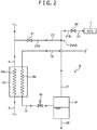
- FIG. 2 is a schematic configuration diagram showing a re-liquefying system 9 in the boil-off gas recovery system 1 according to the first embodiment.
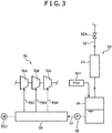
- FIG. 3 is a schematic configuration diagram showing a reuse system 50 in the boil-off gas recovery system 1 according to the first embodiment.
- the boil-off gas recovery system 1 is installed in a ship that transports a liquefied gas such as a liquefied natural gas.
- the boil-off gas recovery system 1 mainly includes a tank 2, a compressor group 3, a cooler 51, a separator 14 (oil separation unit), the re-liquefying system 9, the reuse system 50, pipes connecting these constituent elements to each other, and various control valves provided in the pipes.
- the tank 2 is to store a liquefied gas 100 such as a liquefied natural gas.
- the liquefied natural gas is stored in the tank 2 in a temperature state of about -160°C.
- a boil-off gas 100A is generated.
- the tank 2 is not limited to the one to store the liquefied natural gas but may be the one to store other types of the liquefied gas 100 such as a liquefied petroleum gas.
- the compressor group 3 is connected to the tank 2 via a first pipe 4.
- the boil-off gas 100A generated in the tank 2 passes through the inside of the first pipe 4 and is supplied to the compressor group 3.
- the compressor group 3 includes a non-oil supply type compressor 3a that does not require lubricating oil, and an oil supply type compressor 3b that requires the lubricating oil.
- the non-oil supply type and oil supply type compressors 3a, 3b compress the boil-off gas 100A generated due to vaporization of part of the liquefied gas 100 in the tank 2.
- the oil supply type compressor 3b is arranged in a subsequent part of the non-oil supply type compressor 3a.
- the non-oil supply type compressor 3a may be omitted.
- the non-oil supply type compressor 3a has two compression stages 3aa.
- the oil supply type compressor 3b has three compression stages 3bb.
- the number of the compression stages can be set in accordance with the types of the liquefied gas 100 so that pressure of the boil-off gas can be boosted to be pressure required for re-liquefaction. Therefore, the number of the compression stages is not limited to five of the present embodiment but may be four or less or may be six or more.
- Each of the non-oil supply type and oil supply type compressors 3a, 3b is a reciprocating compressor. That is, the compressors 3a, 3b boost the pressure of the boil-off gas suctioned into a cylinder via a suction port by reciprocating motion of a piston and discharge the boil-off gas whose pressure is boosted from a discharge port.
- a cylinder valve is provided in each of the suction port and the discharge port.
- Poly- ⁇ -olefin (PAO) lubricating oil is supplied to the oil supply type compressor 3b.
- the poly- ⁇ -olefin lubricating oil has a narrower molecular mass distribution and much less vapor pressure than mineral lubricating oil generally used in a reciprocating compressor. That is, the poly- ⁇ -olefin lubricating oil has a much less vaporous component than the mineral lubricating oil.
- the lubricating oil used in the compressor 3b can be mixed into the boil-off gas discharged from the oil supply type compressor 3b.
- the poly- ⁇ -olefin lubricating oil contains base oil made of poly- ⁇ -olefin or the hydrogenated product of poly- ⁇ -olefin, and various additive agents.
- Poly- ⁇ -olefin is an oligomer or a polymer obtained by polymerizing a straight-chain alpha-olefin having a double bond at a terminal (alpha position) as a material.
- the poly- ⁇ -olefin lubricating oil is synthesized lubricating oil characterized in a high viscosity index and a low pour point.
- ⁇ -olefin of 3 to 20 carbons can be used, and ⁇ -olefin of 8 to 12 carbons is preferably used.
- the ⁇ -olefin includes propylene, 1-butene, 1-pentene, 1-hexene, 1-octene, 1-nonene, 1-decene, 1-dodecene, 1-tridecene, 1-tetradecene, 1-pentadecene, 1-hexadecene, 1-heptadecene, 1-octadecene, 1-nonadecene, and 1-eicosene.
- ⁇ -olefin selected from the group consisting of 1-octene, 1-decene, and 1-dodecene is preferable, and 1-decene is more preferable.
- the cooler 51 is to cool the boil-off gas compressed by the compressors 3a, 3b, and is arranged in a subsequent part of the compressors 3a, 3b.
- the cooler 51 cools the boil-off gas by heat exchange with using sea water, for example.
- a temperature of the boil-off gas supplied to an engine 6 and the like can be adjusted to be a predetermined temperature.
- the oil content in a vaporous state contained in the boil-off gas can also be condensed.
- the separator 14 is to separate poly- ⁇ -olefin lubricating oil in a liquid state (mist state) contained in the boil-off gas which is discharged from the compressor 3b, and is arranged in a subsequent part of the cooler 51.
- the separator 14 is connected to the compressor 3b via a second pipe 5.
- the cooler 51 is provided in the middle of the second pipe 5.
- the separator 14 has a main body portion 25 having a cylindrical shape, and a small diameter portion 26 having a cylindrical shape whose diameter is smaller than that of the main body portion 25, the small diameter portion being arranged in the main body portion 25. An outer surface of this small diameter portion 26 is formed in a mesh shape.
- the boil-off gas cooled by the cooler 51 passes through the inside of the second pipe 5 and flows into the small diameter portion 26 from the upper end side of the small diameter portion 26 of the separator 14. As shown by a broken line in FIG. 1 , the boil-off gas flows from an upper end toward a lower end in the small diameter portion 26 and then passes through the mesh on the outer surface of the small diameter portion 26. At this time, the lubricating oil in a mist state contained in the boil-off gas does not pass through the mesh but is accumulated on a bottom of the small diameter portion 26. The boil-off gas passes through the mesh of the small diameter portion 26 and then flows out of the separator 14 from a gas outlet provided on a side surface of the main body portion 25.
- the lubricating oil contained in the boil-off gas can be separated.
- the oil content accumulated on the bottom of the small diameter portion 26 passes through mesh holes and drips down to a bottom of the main body portion 25 (reference numeral 101 in FIG. 1 ).
- a level sensor 24 that detects whether or not a liquid level of the oil content 101 accumulated on the bottom of the main body portion 25 exceeds a predetermined reference level is provided in the separator 14.
- a gas outlet pipe 5A is connected to a gas outlet of the separator 14. As shown in FIG. 1 , the gas outlet pipe 5A branches into three at a first part 5AA.
- the branching pipes are connected to the engine 6, a gas combustion unit 7, and a generator 8, respectively.
- the boil-off gas from which the oil content in a liquid state is already removed by the separator 14 can be respectively supplied to the engine 6, the gas combustion unit 7, and the generator 8.
- Control valves may be respectively provided in the branching pipes. By controlling open/close of these control valves, supply amounts of the boil-off gas to the engine 6, the gas combustion unit 7, and the generator 8 can be adjusted.
- the engine 6 generates propulsion force for a ship by combusting the supplied boil-off gas.
- the generator 8 generates electric power required for driving various devices of the ship by performing power generation with the supplied boil-off gas as fuel.
- the gas combustion unit 7 combusts and safely processes an extra boil-off gas in a case where a generation amount of the boil-off gas exceeds an amount required as fuel for the engine 6 and the generator 8.
- the re-liquefying system 9 cools and expands to re-liquefy the boil-off gas whose pressure is boosted by the compressors 3a, 3b.
- the re-liquefying system 9 mainly has a third pipe 10, a heat exchanger 16, a fourth pipe 17, an expansion valve 18, a gas-liquid separation unit 19, a fifth pipe 21, and a sixth pipe 20.
- the third pipe 10 has one end connected to a second part 5AB of the gas outlet pipe 5A placed on the upstream side of the first part 5AA, and the other end connected to the heat exchanger 16.
- the boil-off gas from which the oil content in a liquid state is already separated by the separator 14 passes through the gas outlet pipe 5A, flows into the third pipe 10 from the second part 5AB, and is supplied to the heat exchanger 16.
- a first control valve 29 is provided in the third pipe 10. By controlling open/close of this valve, an amount of the boil-off gas flowing into the third pipe 10 from the gas outlet pipe 5A can be adjusted.
- the heat exchanger 16 cools the boil-off gas to a liquefiable temperature (for example, -100°C). As shown in FIG. 2 , the heat exchanger 16 has a low-temperature side passage 16a through which the boil-off gas fed to the compressors 3a, 3b from the tank 2 passes, and a high-temperature side passage 16b through which the boil-off gas from which the oil content (poly- ⁇ -olefin lubricating oil) in a liquid state is already separated by the separator 14 passes.
- a liquefiable temperature for example, -100°C.
- the heat exchanger 16 performs heat exchange between the boil-off gas supplied to the compressors 3a, 3b from the tank 2 (boil-off gas passing through the low-temperature side passage 16a) and the boil-off gas from which the oil content in a liquid state is already separated by the separator 14 (boil-off gas passing through the high-temperature side passage 16b).
- the boil-off gas passing through the high-temperature side passage 16b is cooled.
- part of the boil-off gas may be liquefied.
- the boil-off gas passing through the low-temperature side passage 16a is heated, for example, from -160°C to -50°C.
- the first pipe 4 is connected to an inlet and an outlet of the low-temperature side passage 16a.
- the other end of the third pipe 10 is connected to an inlet of the high-temperature side passage 16b.
- One end of the fourth pipe 17 is connected to an outlet of the high-temperature side passage 16b.
- the fourth pipe 17 has the one end connected to the heat exchanger 16, and the other end connected to the gas-liquid separation unit 19.
- the expansion valve 18 is to expand the boil-off gas cooled in the heat exchanger 16 to reduce the pressure, and is provided in the middle of the fourth pipe 17. By this expansion valve 18, part of the boil-off gas is liquefied.
- the gas-liquid separation unit 19 is to separate the boil-off gas partly liquefied by the heat exchanger 16 and the expansion valve 18 into a liquid component and a gas component.
- One end of the fifth pipe 21 and one end of the sixth pipe 20 are respectively connected to the gas-liquid separation unit 19.
- the sixth pipe 20 has the one end connected to a bottom portion of the gas-liquid separation unit 19, and the other end connected to the tank 2. Thereby, the liquid component of the boil-off gas separated in the gas-liquid separation unit 19 can be returned to the tank 2 via the sixth pipe 20.
- the fifth pipe 21 connects the gas-liquid separation unit 19 and the first pipe 4 to each other, and also connects the gas-liquid separation unit 19 and the gas combustion unit 7 to each other. More specifically, the fifth pipe 21 branches into two branching pipes 21A, 21B at a first part 21AA. One branching pipe 21A is connected to the first pipe 4 on the outlet side of the heat exchanger 16, and the other branching pipe 21B is connected to the gas combustion unit 7. Thereby, the gas component of the boil-off gas separated in the gas-liquid separation unit 19 can respectively flow into the first pipe 4 and the gas combustion unit 7 via the fifth pipe 21.
- a second control valve 31 and a third control valve 30 are respectively provided in the branching pipes 21A, 21B.
- opening degrees of flow passages of the boil-off gas in the branching pipes 21A, 21B can be adjusted.
- an amount of the boil-off gas flowing into the side of the first pipe 4 and an amount of the boil-off gas flowing into the side of the gas combustion unit 7 can be respectively adjusted.
- the reuse system 50 is to return the lubricating oil (poly- ⁇ -olefin lubricating oil) in a liquid state separated from the boil-off gas by the separator 14 to the oil supply type compressor 3b.
- the reuse system 50 mainly has a first oil pipe 52, a fourth control valve 52A, a strainer 53, an oil tank 54, an oil supplementation source 551, a second oil pipe 57, an oil pump 56, an oil charging unit 55, and plural (three in the present embodiment) third oil pipes 55A, 55B, 55C.
- the first oil pipe 52 has one end connected to a bottom portion of the main body portion 25 in the separator 14, and the other end connected to an upper portion of the oil tank 54.
- the fourth control valve 52A and the strainer 53 are provided in the first oil pipe 52. As shown in FIG. 3 , the strainer 53 is provided on the downstream side of the fourth control valve 52A.
- the fourth control valve 52A By opening the fourth control valve 52A, the lubricating oil accumulated on the bottom of the separator 14 (main body portion 25) can flow into the first oil pipe 52.
- the fourth control valve 52A may be opened when the level sensor 24 detects the fact that the liquid level of the oil content 101 exceeds the predetermined reference level. By the lubricating oil passing through the strainer 53, foreign substances and the like contained in the lubricating oil can be removed.
- the oil tank 54 stores the lubricating oil from which foreign substances are removed by the strainer 53.
- the oil supplementation source 551 for supplementing unused poly- ⁇ -olefin lubricating oil is connected to the oil tank 54. Thereby, by adding the unused lubricating oil to the lubricating oil recovered by the separator 14 from the oil supplementation source 551, an amount of the lubricating oil in the oil tank 54 can be adjusted.
- the second oil pipe 57 has one end connected to a lower portion of the oil tank 54, and the other end connected to an inlet of the oil charging unit 55.
- the oil pump 56 is provided in the middle of the second oil pipe 57. By activating this oil pump 56, the lubricating oil stored in the oil tank 54 can be supplied to the oil charging unit 55 via the second oil pipe 57.
- the oil charging unit 55 is to supply the lubricating oil to the oil supply type compressor 3b.
- the oil charging unit 55 is activated by a motor 55D.
- the oil charging unit 55 has plural (three in the present embodiment) outlets, and one ends of the third oil pipes 55A, 55B, 55C are respectively connected to the outlets.
- the other ends of the third oil pipes 55A, 55B, 55C are respectively connected to the compression stages 3bb.
- the number of the outlets in the oil charging unit 55 and the number of the third oil pipes are the same as the number of the compression stages in the oil supply type compressor 3b.
- the lubricating oil can be supplied to the oil supply type compressor 3b from the oil charging unit 55 via the third oil pipes 55A, 55B, 55C.
- the poly- ⁇ -olefin lubricating oil recovered by the separator 14 can be returned to the oil supply type compressor 3b and reused as lubricating oil for the piston.
- the above boil-off gas recovery system 1 includes the tank 2 where the liquefied gas 100 is stored, the reciprocating compressor 3b to which the poly- ⁇ -olefin lubricating oil is supplied, the compressor that compresses the boil-off gas 100A generated by vaporization of part of the liquefied gas 100 in the tank 2, the separator 14 (oil separation unit) that separates the poly- ⁇ -olefin lubricating oil in a mist state contained in the boil-off gas which is discharged from the compressor 3b, and the re-liquefying system 9 having the heat exchanger 16 that cools the boil-off gas from which the poly- ⁇ -olefin lubricating oil in a mist state is already separated by the separator 14 by heat exchange with the boil-off gas supplied to the compressor 3b from the tank 2, the re-liquefying system where the liquefied boil-off gas is returned to the tank 2.
- the above boil-off gas recovery system 1 includes the compressor 3b to which the poly- ⁇ -olefin lubricating oil is supplied.
- the poly- ⁇ -olefin lubricating oil has much less vapor pressure than the mineral lubricating oil generally used in the reciprocating compressor. Therefore, in comparison to the boil-off gas recovery system including the reciprocating compressor in which the mineral lubricating oil is used, the amount of the oil content in a vaporous state contained in the boil-off gas which is discharged from the compressor 3b can be reduced to a great extent.
- the separator 14 by separating the oil content in a mist state or a liquid state contained in the boil-off gas after compression by the separator 14, the amount of the oil content flowing into the heat exchanger 16 of the re-liquefying system 9 can be reduced to a great extent. Therefore, since precipitation of the oil content in a flow passage of the heat exchanger 16 is suppressed, performance deterioration of the heat exchanger 16 can be suppressed.
- the above boil-off gas recovery system 1 includes the reuse system 50 where the poly- ⁇ -olefin lubricating oil separated by the separator 14 is returned to the compressor 3b.
- the reuse system 50 By reusing the poly- ⁇ -olefin lubricating oil by this reuse system 50, cost can be reduced.
- the poly- ⁇ -olefin lubricating oil is expensive, a cost reduction effect by including the reuse system 50 is remarkable.
- the boil-off gas recovery system 1 includes the lubricating oil reuse system 50 .
- the present invention is not limited to this.
- a boil-off gas recovery system 1A where a lubricating oil reuse system is omitted may be provided.
- the cooler 51 may be omitted.
- the lubricating oil is separated from the boil-off gas by using the separator 14 having the small diameter portion 26 whose outer surface is formed in a mesh shape is described as one example of the oil separation unit.
- the lubricating oil can also be separated by other oil separation units.
- an oil separation unit using a baffle plate or an oil separation unit of centrifugal separation may be used.
- the configuration in which the boil-off gas after passing through the last compression stage 3bb is guided to the re-liquefying system 9 is described.
- the present invention is not limited to this.
- the third pipe 10 in the re-liquefying system 9 may be connected to a portion between the compression stages 3bb in the oil supply type compressor 3b.
- the cooler 51 and the separator 14 are also arranged in the portion between the compression stages 3bb. Thereby, the boil-off gas extracted from a middle part of the compressor 3b can be guided to the re-liquefying system 9.
- each of the third oil pipes 55A, 55B, 55C may be connected to a portion between the compression stages 3aa, 3bb.
- the present invention is not limited to the configuration in which the lubricating oil recovered by the separator 14 and the unused lubricating oil are mixed and then supplied to the oil supply type compressor 3b as in the reuse system 50 in the above first embodiment.
- the lubricating oil recovered by the separator 14 and the unused lubricating oil may be separately supplied to the compressor 3b.
- the oil charging unit 55 may be omitted and the lubricating oil may be supplied to the oil supply type compressor 3b directly from the oil tank 54 by the oil pump 56.
- a boil-off gas recovery system capable of suppressing performance deterioration of a heat exchanger in a boil-off gas re-liquefying system is provided.
- a boil-off gas recovery system includes a tank where a liquefied gas is stored, a reciprocating compressor to which poly- ⁇ -olefin lubricating oil is supplied, the compressor that compresses a boil-off gas generated by vaporization of part of the liquefied gas in the tank, a separator that separates the poly- ⁇ -olefin lubricating oil contained in the boil-off gas which is discharged from the compressor, and a re-liquefying system having a heat exchanger that cools the boil-off gas from which the poly- ⁇ -olefin lubricating oil is already separated by the separator by heat exchange with the boil-off gas supplied to the compressor from the tank, the re-liquefying system where the liquefied boil-off gas is returned to the tank.
Landscapes
- Engineering & Computer Science (AREA)
- Mechanical Engineering (AREA)
- General Engineering & Computer Science (AREA)
- Physics & Mathematics (AREA)
- Thermal Sciences (AREA)
- Chemical & Material Sciences (AREA)
- Chemical Kinetics & Catalysis (AREA)
- General Chemical & Material Sciences (AREA)
- Oil, Petroleum & Natural Gas (AREA)
- Combustion & Propulsion (AREA)
- Analytical Chemistry (AREA)
- Power Engineering (AREA)
- Ocean & Marine Engineering (AREA)
- Filling Or Discharging Of Gas Storage Vessels (AREA)
Abstract
Description
- The present invention relates to a boil-off gas recovery system.
- In a liquefied natural gas transportation ship, since a liquefied natural gas stored in a tank is gasified by heat coming from the outside when transferred at sea, a boil-off gas is generated. This boil-off gas is effectively utilized as fuel for an engine, a steam boiler, or a generator in the ship, and an extra gas is re-liquefied and then returned to the tank. As a technique to re-liquefy the boil-off gas generated in the tank and to return the boil-off gas to the tank in such a way, a boil-off gas recovery system described in
JP 2015-158263 A - In the boil-off gas recovery system of
JP 2015-158263 A FIG. 7 , a boil-off gas generated in atank 11 is compressed by an oilsupply type compressor 15, and part of the compressed boil-off gas is re-liquefied through cooling by aheat exchanger 14 and expansion by anexpansion valve 17 and then returned to thetank 11. Lubricating oil used in thecompressor 15 can be mixed into the boil-off gas discharged from thecompressor 15. Therefore, in the boil-off gas recovery system ofJP 2015-158263 A second pipe 16. - In the boil-off gas recovery system of
JP 2015-158263 A heat exchanger 14, the flow passage is narrowed down. As a result, there is a problem that a heat exchange performance is remarkably deteriorated. - The present invention is achieved in consideration with the above problem, and an object of the present invention is to provide a boil-off gas recovery system capable of suppressing performance deterioration of a heat exchanger in a boil-off gas re-liquefying system.
- A boil-off gas recovery system according to one aspect of the present invention includes a tank where a liquefied gas is stored, a reciprocating compressor to which poly-α-olefin lubricating oil is supplied, the compressor that compresses a boil-off gas generated by vaporization of part of the liquefied gas in the tank, an oil separation unit that separates the poly-α-olefin lubricating oil contained in the boil-off gas which is discharged from the compressor, and a re-liquefying system having a heat exchanger that cools the boil-off gas from which the poly-α-olefin lubricating oil is already separated by the oil separation unit by heat exchange with the boil-off gas supplied to the compressor from the tank, the re-liquefying system where the liquefied boil-off gas is returned to the tank.
- The above boil-off gas recovery system includes the compressor to which the poly-α-olefin lubricating oil is supplied. The poly-α-olefin lubricating oil has much less vapor pressure than mineral lubricating oil generally used in a reciprocating compressor. Therefore, in comparison to a boil-off gas recovery system including the reciprocating compressor in which the mineral lubricating oil is used, an amount of oil content in a vaporous state contained in the boil-off gas which is discharged from the compressor can be reduced to a great extent. Thus, by separating the oil content in a mist state or a liquid state contained in the boil-off gas after compression by the oil separation unit, an amount of the oil content flowing into the heat exchanger in the re-liquefying system can be reduced to a great extent. Therefore, since precipitation of the oil content in a flow passage of the heat exchanger is suppressed, performance deterioration of the heat exchanger can be suppressed.
- The above boil-off gas recovery system may further include a reuse system where the poly-α-olefin lubricating oil separated by the oil separation unit is returned to the compressor.
- With this configuration, by reusing the poly-α-olefin lubricating oil, cost can be reduced. In particular, since the poly-α-olefin lubricating oil is expensive, a cost reduction effect by including the reuse system is remarkable.
- As clear from the above description, according to the present invention, the boil-off gas recovery system capable of suppressing the performance deterioration of the heat exchanger in the boil-off gas re-liquefying system can be provided.
-
-
FIG. 1 is a diagram schematically showing a configuration of a boil-off gas recovery system according to a first embodiment of the present invention. -
FIG. 2 is a diagram schematically showing a configuration of a re-liquefying system provided in the above boil-off gas recovery system. -
FIG. 3 is a diagram schematically showing a configuration of a reuse system provided in the above boil-off gas recovery system. -
FIG. 4 is a diagram schematically showing a configuration of a boil-off gas recovery system according to one of other embodiments of the present invention. -
FIG. 5 is a diagram schematically showing a configuration of a boil-off gas recovery system according to one of other embodiments of the present invention. -
FIG. 6 is a diagram schematically showing a configuration of a boil-off gas recovery system according to one of other embodiments of the present invention. -
FIG. 7 is a diagram schematically showing a configuration of a boil-off gas recovery system according to the conventional example. - Hereinafter, a boil-off gas recovery system according to embodiments of the present invention will be described in detail on the basis of the drawings.
- Firstly, a boil-off
gas recovery system 1 according to a first embodiment of the present invention will be described with reference toFIGS. 1 to 3 .FIG. 1 is a schematic configuration diagram showing the boil-offgas recovery system 1 according to the first embodiment.FIG. 2 is a schematic configuration diagram showing a re-liquefyingsystem 9 in the boil-offgas recovery system 1 according to the first embodiment.FIG. 3 is a schematic configuration diagram showing areuse system 50 in the boil-offgas recovery system 1 according to the first embodiment. - The boil-off
gas recovery system 1 is installed in a ship that transports a liquefied gas such as a liquefied natural gas. As shown inFIG. 1 , the boil-offgas recovery system 1 mainly includes atank 2, acompressor group 3, acooler 51, a separator 14 (oil separation unit), the re-liquefyingsystem 9, thereuse system 50, pipes connecting these constituent elements to each other, and various control valves provided in the pipes. - The
tank 2 is to store a liquefiedgas 100 such as a liquefied natural gas. The liquefied natural gas is stored in thetank 2 in a temperature state of about -160°C. In thetank 2, by vaporization of part of the liquefiedgas 100 due to in-coming of heat from the outside, a boil-offgas 100A is generated. Thetank 2 is not limited to the one to store the liquefied natural gas but may be the one to store other types of the liquefiedgas 100 such as a liquefied petroleum gas. - The
compressor group 3 is connected to thetank 2 via afirst pipe 4. The boil-offgas 100A generated in thetank 2 passes through the inside of thefirst pipe 4 and is supplied to thecompressor group 3. Thecompressor group 3 includes a non-oilsupply type compressor 3a that does not require lubricating oil, and an oilsupply type compressor 3b that requires the lubricating oil. The non-oil supply type and oilsupply type compressors gas 100A generated due to vaporization of part of the liquefiedgas 100 in thetank 2. The oilsupply type compressor 3b is arranged in a subsequent part of the non-oilsupply type compressor 3a. The non-oilsupply type compressor 3a may be omitted. - The non-oil
supply type compressor 3a has two compression stages 3aa. The oilsupply type compressor 3b has three compression stages 3bb. The number of the compression stages can be set in accordance with the types of the liquefiedgas 100 so that pressure of the boil-off gas can be boosted to be pressure required for re-liquefaction. Therefore, the number of the compression stages is not limited to five of the present embodiment but may be four or less or may be six or more. - Each of the non-oil supply type and oil
supply type compressors compressors - Poly-α-olefin (PAO) lubricating oil is supplied to the oil
supply type compressor 3b. The poly-α-olefin lubricating oil has a narrower molecular mass distribution and much less vapor pressure than mineral lubricating oil generally used in a reciprocating compressor. That is, the poly-α-olefin lubricating oil has a much less vaporous component than the mineral lubricating oil. The lubricating oil used in thecompressor 3b can be mixed into the boil-off gas discharged from the oilsupply type compressor 3b. However, by using the poly-α-olefin lubricating oil having a less vaporous component, an amount of oil content in a vaporous state contained in the boil-off gas which is discharged from the oilsupply type compressor 3b can be reduced to a great extent. - The poly-α-olefin lubricating oil contains base oil made of poly-α-olefin or the hydrogenated product of poly-α-olefin, and various additive agents. Poly-α-olefin is an oligomer or a polymer obtained by polymerizing a straight-chain alpha-olefin having a double bond at a terminal (alpha position) as a material. The poly-α-olefin lubricating oil is synthesized lubricating oil characterized in a high viscosity index and a low pour point.
- As a monomer used for polymerization of poly-α-olefin, for example, α-olefin of 3 to 20 carbons can be used, and α-olefin of 8 to 12 carbons is preferably used. Specifically, the α-olefin includes propylene, 1-butene, 1-pentene, 1-hexene, 1-octene, 1-nonene, 1-decene, 1-dodecene, 1-tridecene, 1-tetradecene, 1-pentadecene, 1-hexadecene, 1-heptadecene, 1-octadecene, 1-nonadecene, and 1-eicosene. In particular, α-olefin selected from the group consisting of 1-octene, 1-decene, and 1-dodecene is preferable, and 1-decene is more preferable.
- The cooler 51 is to cool the boil-off gas compressed by the
compressors compressors engine 6 and the like can be adjusted to be a predetermined temperature. At this time, the oil content in a vaporous state contained in the boil-off gas can also be condensed. - The
separator 14 is to separate poly-α-olefin lubricating oil in a liquid state (mist state) contained in the boil-off gas which is discharged from thecompressor 3b, and is arranged in a subsequent part of the cooler 51. Theseparator 14 is connected to thecompressor 3b via asecond pipe 5. The cooler 51 is provided in the middle of thesecond pipe 5. As shown inFIG. 1 , theseparator 14 has amain body portion 25 having a cylindrical shape, and asmall diameter portion 26 having a cylindrical shape whose diameter is smaller than that of themain body portion 25, the small diameter portion being arranged in themain body portion 25. An outer surface of thissmall diameter portion 26 is formed in a mesh shape. - The boil-off gas cooled by the cooler 51 passes through the inside of the
second pipe 5 and flows into thesmall diameter portion 26 from the upper end side of thesmall diameter portion 26 of theseparator 14. As shown by a broken line inFIG. 1 , the boil-off gas flows from an upper end toward a lower end in thesmall diameter portion 26 and then passes through the mesh on the outer surface of thesmall diameter portion 26. At this time, the lubricating oil in a mist state contained in the boil-off gas does not pass through the mesh but is accumulated on a bottom of thesmall diameter portion 26. The boil-off gas passes through the mesh of thesmall diameter portion 26 and then flows out of theseparator 14 from a gas outlet provided on a side surface of themain body portion 25. In such a way, by using a mesh structure of thesmall diameter portion 26, the lubricating oil contained in the boil-off gas can be separated. The oil content accumulated on the bottom of thesmall diameter portion 26 passes through mesh holes and drips down to a bottom of the main body portion 25 (reference numeral 101 inFIG. 1 ). Alevel sensor 24 that detects whether or not a liquid level of theoil content 101 accumulated on the bottom of themain body portion 25 exceeds a predetermined reference level is provided in theseparator 14. - One end of a
gas outlet pipe 5A is connected to a gas outlet of theseparator 14. As shown inFIG. 1 , thegas outlet pipe 5A branches into three at a first part 5AA. The branching pipes are connected to theengine 6, agas combustion unit 7, and agenerator 8, respectively. Thereby, the boil-off gas from which the oil content in a liquid state is already removed by theseparator 14 can be respectively supplied to theengine 6, thegas combustion unit 7, and thegenerator 8. Control valves (not shown) may be respectively provided in the branching pipes. By controlling open/close of these control valves, supply amounts of the boil-off gas to theengine 6, thegas combustion unit 7, and thegenerator 8 can be adjusted. - The
engine 6 generates propulsion force for a ship by combusting the supplied boil-off gas. Thegenerator 8 generates electric power required for driving various devices of the ship by performing power generation with the supplied boil-off gas as fuel. Thegas combustion unit 7 combusts and safely processes an extra boil-off gas in a case where a generation amount of the boil-off gas exceeds an amount required as fuel for theengine 6 and thegenerator 8. - Next, the
re-liquefying system 9 provided in the above boil-offgas recovery system 1 will be described mainly with reference toFIGS. 1 and2 . There-liquefying system 9 cools and expands to re-liquefy the boil-off gas whose pressure is boosted by thecompressors re-liquefying system 9 mainly has athird pipe 10, aheat exchanger 16, afourth pipe 17, anexpansion valve 18, a gas-liquid separation unit 19, afifth pipe 21, and asixth pipe 20. - The
third pipe 10 has one end connected to a second part 5AB of thegas outlet pipe 5A placed on the upstream side of the first part 5AA, and the other end connected to theheat exchanger 16. Thereby, the boil-off gas from which the oil content in a liquid state is already separated by theseparator 14 passes through thegas outlet pipe 5A, flows into thethird pipe 10 from the second part 5AB, and is supplied to theheat exchanger 16. As shown inFIG. 1 , afirst control valve 29 is provided in thethird pipe 10. By controlling open/close of this valve, an amount of the boil-off gas flowing into thethird pipe 10 from thegas outlet pipe 5A can be adjusted. - The
heat exchanger 16 cools the boil-off gas to a liquefiable temperature (for example, -100°C). As shown inFIG. 2 , theheat exchanger 16 has a low-temperature side passage 16a through which the boil-off gas fed to thecompressors tank 2 passes, and a high-temperature side passage 16b through which the boil-off gas from which the oil content (poly-α-olefin lubricating oil) in a liquid state is already separated by theseparator 14 passes. - The
heat exchanger 16 performs heat exchange between the boil-off gas supplied to thecompressors temperature side passage 16a) and the boil-off gas from which the oil content in a liquid state is already separated by the separator 14 (boil-off gas passing through the high-temperature side passage 16b). By this heat exchange, the boil-off gas passing through the high-temperature side passage 16b is cooled. At this time, part of the boil-off gas may be liquefied. The boil-off gas passing through the low-temperature side passage 16a is heated, for example, from -160°C to -50°C. - As shown in
FIG. 2 , thefirst pipe 4 is connected to an inlet and an outlet of the low-temperature side passage 16a. The other end of thethird pipe 10 is connected to an inlet of the high-temperature side passage 16b. One end of thefourth pipe 17 is connected to an outlet of the high-temperature side passage 16b. - The
fourth pipe 17 has the one end connected to theheat exchanger 16, and the other end connected to the gas-liquid separation unit 19. Theexpansion valve 18 is to expand the boil-off gas cooled in theheat exchanger 16 to reduce the pressure, and is provided in the middle of thefourth pipe 17. By thisexpansion valve 18, part of the boil-off gas is liquefied. - The gas-
liquid separation unit 19 is to separate the boil-off gas partly liquefied by theheat exchanger 16 and theexpansion valve 18 into a liquid component and a gas component. One end of thefifth pipe 21 and one end of thesixth pipe 20 are respectively connected to the gas-liquid separation unit 19. - The
sixth pipe 20 has the one end connected to a bottom portion of the gas-liquid separation unit 19, and the other end connected to thetank 2. Thereby, the liquid component of the boil-off gas separated in the gas-liquid separation unit 19 can be returned to thetank 2 via thesixth pipe 20. - The
fifth pipe 21 connects the gas-liquid separation unit 19 and thefirst pipe 4 to each other, and also connects the gas-liquid separation unit 19 and thegas combustion unit 7 to each other. More specifically, thefifth pipe 21 branches into two branchingpipes pipe 21A is connected to thefirst pipe 4 on the outlet side of theheat exchanger 16, and the other branchingpipe 21B is connected to thegas combustion unit 7. Thereby, the gas component of the boil-off gas separated in the gas-liquid separation unit 19 can respectively flow into thefirst pipe 4 and thegas combustion unit 7 via thefifth pipe 21. - As shown in
FIG. 2 , asecond control valve 31 and athird control valve 30 are respectively provided in the branchingpipes pipes first pipe 4 and an amount of the boil-off gas flowing into the side of thegas combustion unit 7 can be respectively adjusted. - Next, the
reuse system 50 provided in the above boil-offgas recovery system 1 will be described mainly with reference toFIGS. 1 and3 . Thereuse system 50 is to return the lubricating oil (poly-α-olefin lubricating oil) in a liquid state separated from the boil-off gas by theseparator 14 to the oilsupply type compressor 3b. As shown inFIG. 3 , thereuse system 50 mainly has afirst oil pipe 52, afourth control valve 52A, astrainer 53, anoil tank 54, anoil supplementation source 551, asecond oil pipe 57, anoil pump 56, anoil charging unit 55, and plural (three in the present embodiment)third oil pipes - The
first oil pipe 52 has one end connected to a bottom portion of themain body portion 25 in theseparator 14, and the other end connected to an upper portion of theoil tank 54. Thefourth control valve 52A and thestrainer 53 are provided in thefirst oil pipe 52. As shown inFIG. 3 , thestrainer 53 is provided on the downstream side of thefourth control valve 52A. - By opening the
fourth control valve 52A, the lubricating oil accumulated on the bottom of the separator 14 (main body portion 25) can flow into thefirst oil pipe 52. Thefourth control valve 52A may be opened when thelevel sensor 24 detects the fact that the liquid level of theoil content 101 exceeds the predetermined reference level. By the lubricating oil passing through thestrainer 53, foreign substances and the like contained in the lubricating oil can be removed. - The
oil tank 54 stores the lubricating oil from which foreign substances are removed by thestrainer 53. Theoil supplementation source 551 for supplementing unused poly-α-olefin lubricating oil is connected to theoil tank 54. Thereby, by adding the unused lubricating oil to the lubricating oil recovered by theseparator 14 from theoil supplementation source 551, an amount of the lubricating oil in theoil tank 54 can be adjusted. - The
second oil pipe 57 has one end connected to a lower portion of theoil tank 54, and the other end connected to an inlet of theoil charging unit 55. Theoil pump 56 is provided in the middle of thesecond oil pipe 57. By activating thisoil pump 56, the lubricating oil stored in theoil tank 54 can be supplied to theoil charging unit 55 via thesecond oil pipe 57. - The
oil charging unit 55 is to supply the lubricating oil to the oilsupply type compressor 3b. Theoil charging unit 55 is activated by amotor 55D. Theoil charging unit 55 has plural (three in the present embodiment) outlets, and one ends of thethird oil pipes third oil pipes oil charging unit 55 and the number of the third oil pipes are the same as the number of the compression stages in the oilsupply type compressor 3b. Thereby, the lubricating oil can be supplied to the oilsupply type compressor 3b from theoil charging unit 55 via thethird oil pipes separator 14 can be returned to the oilsupply type compressor 3b and reused as lubricating oil for the piston. - Next, characteristic configurations and operations and effects of the boil-off
gas recovery system 1 according to the above first embodiment will be described. - The above boil-off
gas recovery system 1 includes thetank 2 where the liquefiedgas 100 is stored, thereciprocating compressor 3b to which the poly-α-olefin lubricating oil is supplied, the compressor that compresses the boil-offgas 100A generated by vaporization of part of the liquefiedgas 100 in thetank 2, the separator 14 (oil separation unit) that separates the poly-α-olefin lubricating oil in a mist state contained in the boil-off gas which is discharged from thecompressor 3b, and there-liquefying system 9 having theheat exchanger 16 that cools the boil-off gas from which the poly-α-olefin lubricating oil in a mist state is already separated by theseparator 14 by heat exchange with the boil-off gas supplied to thecompressor 3b from thetank 2, the re-liquefying system where the liquefied boil-off gas is returned to thetank 2. - The above boil-off
gas recovery system 1 includes thecompressor 3b to which the poly-α-olefin lubricating oil is supplied. The poly-α-olefin lubricating oil has much less vapor pressure than the mineral lubricating oil generally used in the reciprocating compressor. Therefore, in comparison to the boil-off gas recovery system including the reciprocating compressor in which the mineral lubricating oil is used, the amount of the oil content in a vaporous state contained in the boil-off gas which is discharged from thecompressor 3b can be reduced to a great extent. Thus, by separating the oil content in a mist state or a liquid state contained in the boil-off gas after compression by theseparator 14, the amount of the oil content flowing into theheat exchanger 16 of there-liquefying system 9 can be reduced to a great extent. Therefore, since precipitation of the oil content in a flow passage of theheat exchanger 16 is suppressed, performance deterioration of theheat exchanger 16 can be suppressed. - With the above boil-off
gas recovery system 1, precipitation of the oil content in thefourth pipe 17 placed on the downstream side of theheat exchanger 16 can also be suppressed. When the oil content is condensed and precipitated in thefourth pipe 17, at the time of re-start of the system or the like, there is a possibility that the oil content brought into a liquid state under a normal temperature is brought to the downstream side together with the boil-off gas and mixed into thetank 2. For this, with the above boil-offgas recovery system 1, the precipitation of the oil content in thefourth pipe 17 can also be suppressed. Thus, mixture of the oil content into thetank 2 can also be prevented. - The above boil-off
gas recovery system 1 includes thereuse system 50 where the poly-α-olefin lubricating oil separated by theseparator 14 is returned to thecompressor 3b. By reusing the poly-α-olefin lubricating oil by thisreuse system 50, cost can be reduced. In particular, since the poly-α-olefin lubricating oil is expensive, a cost reduction effect by including thereuse system 50 is remarkable. - Finally, other embodiments of the present invention will be described.
- In the above first embodiment, the case where the boil-off
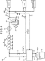
gas recovery system 1 includes the lubricatingoil reuse system 50 is described. However, the present invention is not limited to this. As shown inFIG. 4 , a boil-offgas recovery system 1A where a lubricating oil reuse system is omitted may be provided. - In the boil-off
gas recovery system 1 according to the above first embodiment, the cooler 51 may be omitted. - In the above first embodiment, the case where the lubricating oil is separated from the boil-off gas by using the
separator 14 having thesmall diameter portion 26 whose outer surface is formed in a mesh shape is described as one example of the oil separation unit. However, the lubricating oil can also be separated by other oil separation units. For example, an oil separation unit using a baffle plate or an oil separation unit of centrifugal separation may be used. - In the above first embodiment, the configuration in which the boil-off gas after passing through the last compression stage 3bb is guided to the
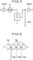
re-liquefying system 9 is described. However, the present invention is not limited to this. As shown inFIG. 5 , thethird pipe 10 in there-liquefying system 9 may be connected to a portion between the compression stages 3bb in the oilsupply type compressor 3b. In this case, the cooler 51 and theseparator 14 are also arranged in the portion between the compression stages 3bb. Thereby, the boil-off gas extracted from a middle part of thecompressor 3b can be guided to there-liquefying system 9. - In the above first embodiment, the case where the
third oil pipes supply type compressor 3b is described. However, the present invention is not limited to this. As shown inFIG. 6 , each of thethird oil pipes third oil pipes supply type compressor 3b, power required for pressure-feeding the lubricating oil can be less required. - The present invention is not limited to the configuration in which the lubricating oil recovered by the
separator 14 and the unused lubricating oil are mixed and then supplied to the oilsupply type compressor 3b as in thereuse system 50 in the above first embodiment. The lubricating oil recovered by theseparator 14 and the unused lubricating oil may be separately supplied to thecompressor 3b. Theoil charging unit 55 may be omitted and the lubricating oil may be supplied to the oilsupply type compressor 3b directly from theoil tank 54 by theoil pump 56. - The embodiments disclosed herein should be understood as not restriction but only examples in all aspects. The scope of the present invention is indicated not by the above description but by the claims, and is intended to include equivalent meanings to the claims and all modifications within the scope.
- A boil-off gas recovery system capable of suppressing performance deterioration of a heat exchanger in a boil-off gas re-liquefying system is provided.
- A boil-off gas recovery system includes a tank where a liquefied gas is stored, a reciprocating compressor to which poly-α-olefin lubricating oil is supplied, the compressor that compresses a boil-off gas generated by vaporization of part of the liquefied gas in the tank, a separator that separates the poly-α-olefin lubricating oil contained in the boil-off gas which is discharged from the compressor, and a re-liquefying system having a heat exchanger that cools the boil-off gas from which the poly-α-olefin lubricating oil is already separated by the separator by heat exchange with the boil-off gas supplied to the compressor from the tank, the re-liquefying system where the liquefied boil-off gas is returned to the tank.
Claims (2)
- A boil-off gas recovery system comprising:a tank where a liquefied gas is stored;a reciprocating compressor to which poly-α-olefin lubricating oil is supplied, the compressor that compresses a boil-off gas generated by vaporization of part of the liquefied gas in the tank;an oil separation unit that separates the poly-α-olefin lubricating oil contained in the boil-off gas which is discharged from the compressor; anda re-liquefying system having a heat exchanger that cools the boil-off gas from which the poly-α-olefin lubricating oil is already separated by the oil separation unit by heat exchange with the boil-off gas supplied to the compressor from the tank, the re-liquefying system where the liquefied boil-off gas is returned to the tank.
- The boil-off gas recovery system according to claim 1, further comprising:a reuse system where the poly-α-olefin lubricating oil separated by the oil separation unit is returned to the compressor.
Applications Claiming Priority (1)
| Application Number | Priority Date | Filing Date | Title |
|---|---|---|---|
| JP2017019761A JP7057065B2 (en) | 2017-02-06 | 2017-02-06 | Boil-off gas recovery system |
Publications (2)
| Publication Number | Publication Date |
|---|---|
| EP3358285A1 true EP3358285A1 (en) | 2018-08-08 |
| EP3358285B1 EP3358285B1 (en) | 2020-09-23 |
Family
ID=60915368
Family Applications (1)
| Application Number | Title | Priority Date | Filing Date |
|---|---|---|---|
| EP17210805.2A Active EP3358285B1 (en) | 2017-02-06 | 2017-12-28 | Boil-off gas recovery system |
Country Status (4)
| Country | Link |
|---|---|
| EP (1) | EP3358285B1 (en) |
| JP (1) | JP7057065B2 (en) |
| KR (1) | KR102057250B1 (en) |
| CN (1) | CN108397975B (en) |
Cited By (1)
| Publication number | Priority date | Publication date | Assignee | Title |
|---|---|---|---|---|
| US12535268B2 (en) | 2021-04-09 | 2026-01-27 | Honda Motor Co., Ltd. | Fuel cell power-supply management device and fuel cell power-supply management method |
Families Citing this family (8)
| Publication number | Priority date | Publication date | Assignee | Title |
|---|---|---|---|---|
| KR102514084B1 (en) * | 2018-09-18 | 2023-03-24 | 대우조선해양 주식회사 | Lubricating oil separator of boil-off gas reliquefaction system |
| JP7036702B2 (en) * | 2018-10-30 | 2022-03-15 | 株式会社神戸製鋼所 | Compressor |
| KR20220043277A (en) | 2020-09-29 | 2022-04-05 | (주)테크니컬코리아 | Boil-off gas reliquefaction apparatus |
| JPWO2022215307A1 (en) | 2021-04-09 | 2022-10-13 | ||
| CN117120763A (en) | 2021-04-09 | 2023-11-24 | 本田技研工业株式会社 | Fuel cell power supply management device and fuel cell power supply management method |
| JP6922113B1 (en) * | 2021-05-27 | 2021-08-18 | 株式会社神戸製鋼所 | Compressor unit, compressor unit control program and control method |
| KR102499137B1 (en) | 2021-08-11 | 2023-02-13 | (주)테크니컬코리아 | Boil-off gas reliquefaction system |
| JP7623981B2 (en) * | 2022-06-02 | 2025-01-29 | 株式会社神戸製鋼所 | Compressor Unit |
Citations (4)
| Publication number | Priority date | Publication date | Assignee | Title |
|---|---|---|---|---|
| WO2011084813A1 (en) * | 2009-12-21 | 2011-07-14 | E. I. Du Pont De Nemours And Company | Compositions comprising tetrafluoropropene and difluoromethane and uses thereof |
| JP2015158263A (en) | 2014-02-25 | 2015-09-03 | 三井造船株式会社 | boil-off gas recovery system |
| US20160114876A1 (en) * | 2013-06-26 | 2016-04-28 | Daewoo Shipbuilding & Marine Engineering Co., Ltd. | System and method for treating boil-off gas in ship |
| KR20160126955A (en) * | 2016-10-24 | 2016-11-02 | 대우조선해양 주식회사 | Reliquefaction System And Method For Boil Off Gas |
Family Cites Families (5)
| Publication number | Priority date | Publication date | Assignee | Title |
|---|---|---|---|---|
| JP3670528B2 (en) * | 1999-08-31 | 2005-07-13 | 株式会社神戸製鋼所 | Boil-off gas processing method and apparatus for low-temperature liquefied gas |
| US6330811B1 (en) * | 2000-06-29 | 2001-12-18 | Praxair Technology, Inc. | Compression system for cryogenic refrigeration with multicomponent refrigerant |
| CN202012731U (en) * | 2011-03-26 | 2011-10-19 | 宁波鲍斯能源装备股份有限公司 | Device for recovering LNG (liquefied natural gas) evaporated gas and liquefying again |
| JP2014202133A (en) * | 2013-04-05 | 2014-10-27 | 日立アプライアンス株式会社 | Compressor |
| JPWO2016174973A1 (en) * | 2015-04-28 | 2018-03-01 | Kyb株式会社 | Hydraulic oil for hydraulic shock absorber and hydraulic shock absorber |
-
2017
- 2017-02-06 JP JP2017019761A patent/JP7057065B2/en active Active
- 2017-12-28 EP EP17210805.2A patent/EP3358285B1/en active Active
-
2018
- 2018-02-01 KR KR1020180012642A patent/KR102057250B1/en active Active
- 2018-02-06 CN CN201810117672.9A patent/CN108397975B/en active Active
Patent Citations (4)
| Publication number | Priority date | Publication date | Assignee | Title |
|---|---|---|---|---|
| WO2011084813A1 (en) * | 2009-12-21 | 2011-07-14 | E. I. Du Pont De Nemours And Company | Compositions comprising tetrafluoropropene and difluoromethane and uses thereof |
| US20160114876A1 (en) * | 2013-06-26 | 2016-04-28 | Daewoo Shipbuilding & Marine Engineering Co., Ltd. | System and method for treating boil-off gas in ship |
| JP2015158263A (en) | 2014-02-25 | 2015-09-03 | 三井造船株式会社 | boil-off gas recovery system |
| KR20160126955A (en) * | 2016-10-24 | 2016-11-02 | 대우조선해양 주식회사 | Reliquefaction System And Method For Boil Off Gas |
Cited By (1)
| Publication number | Priority date | Publication date | Assignee | Title |
|---|---|---|---|---|
| US12535268B2 (en) | 2021-04-09 | 2026-01-27 | Honda Motor Co., Ltd. | Fuel cell power-supply management device and fuel cell power-supply management method |
Also Published As
| Publication number | Publication date |
|---|---|
| JP2018128038A (en) | 2018-08-16 |
| CN108397975A (en) | 2018-08-14 |
| EP3358285B1 (en) | 2020-09-23 |
| KR20180091722A (en) | 2018-08-16 |
| CN108397975B (en) | 2020-10-23 |
| KR102057250B1 (en) | 2019-12-18 |
| JP7057065B2 (en) | 2022-04-19 |
Similar Documents
| Publication | Publication Date | Title |
|---|---|---|
| EP3358285B1 (en) | Boil-off gas recovery system | |
| KR102534533B1 (en) | Mixed refrigerant liquefaction system and method | |
| CN110914546B (en) | Compression device | |
| RU2533044C2 (en) | Method and device for cooling flow of gaseous hydrocarbons | |
| JP6524485B2 (en) | Boil off gas utilization system | |
| JP6250519B2 (en) | Boil-off gas recovery system | |
| KR102075977B1 (en) | Boil-Off Gas Reliquefaction System and Method of Discharging Lubrication Oil in the Same | |
| JP6371930B1 (en) | Lubricating oil discharge method in evaporative gas reliquefaction system | |
| RU2719258C2 (en) | System and method of treating gas obtained during cryogenic liquid evaporation | |
| WO2015069138A2 (en) | Natural gas liquefaction method and unit | |
| RU2735343C1 (en) | System for repeated liquefaction of boil-off gas and method of removal of lubricating oil from system of repeated liquefaction of boil-off gas | |
| KR102003408B1 (en) | BOG Reliquefaction System for Vessels and Method of Discharging Lubrication Oil in the Same | |
| US20070187340A1 (en) | Process for the treatment of fluids originating from submarine oil fields | |
| RU2738946C1 (en) | System and method of repeated liquefaction of stripping gas for ship | |
| KR102088565B1 (en) | Reliquefaction system for boil-off gas and ship having the same | |
| KR102276354B1 (en) | Boil-Off Gas Re-liquefaction System for Vessels and Method for Operation of the Same | |
| KR101996284B1 (en) | Boil-Off Gas Re-liquefaction System | |
| KR102514081B1 (en) | Lubricating oil separator and boil-off gas reliquefaction system having the lubricating oil separator | |
| JP2018044763A (en) | Boil-off gas recovery system | |
| KR102020967B1 (en) | Boil-Off Gas Reliquefaction System and Method of Discharging lubrication Oil in the Same | |
| CN110678386A (en) | Boil off gas reliquefaction system | |
| KR101818526B1 (en) | Fuel Supply Method and System of Engine for Vessel | |
| KR20200050372A (en) | Compression device | |
| KR101908571B1 (en) | System of Boil-Off Gas Reliquefaction for Vessel | |
| KR102044271B1 (en) | Boil-Off Gas Reliquefaction System and Method for Vessel |
Legal Events
| Date | Code | Title | Description |
|---|---|---|---|
| PUAI | Public reference made under article 153(3) epc to a published international application that has entered the european phase |
Free format text: ORIGINAL CODE: 0009012 |
|
| STAA | Information on the status of an ep patent application or granted ep patent |
Free format text: STATUS: REQUEST FOR EXAMINATION WAS MADE |
|
| 17P | Request for examination filed |
Effective date: 20171228 |
|
| AK | Designated contracting states |
Kind code of ref document: A1 Designated state(s): AL AT BE BG CH CY CZ DE DK EE ES FI FR GB GR HR HU IE IS IT LI LT LU LV MC MK MT NL NO PL PT RO RS SE SI SK SM TR |
|
| AX | Request for extension of the european patent |
Extension state: BA ME |
|
| STAA | Information on the status of an ep patent application or granted ep patent |
Free format text: STATUS: EXAMINATION IS IN PROGRESS |
|
| 17Q | First examination report despatched |
Effective date: 20190130 |
|
| GRAP | Despatch of communication of intention to grant a patent |
Free format text: ORIGINAL CODE: EPIDOSNIGR1 |
|
| STAA | Information on the status of an ep patent application or granted ep patent |
Free format text: STATUS: GRANT OF PATENT IS INTENDED |
|
| INTG | Intention to grant announced |
Effective date: 20200506 |
|
| GRAS | Grant fee paid |
Free format text: ORIGINAL CODE: EPIDOSNIGR3 |
|
| GRAA | (expected) grant |
Free format text: ORIGINAL CODE: 0009210 |
|
| STAA | Information on the status of an ep patent application or granted ep patent |
Free format text: STATUS: THE PATENT HAS BEEN GRANTED |
|
| AK | Designated contracting states |
Kind code of ref document: B1 Designated state(s): AL AT BE BG CH CY CZ DE DK EE ES FI FR GB GR HR HU IE IS IT LI LT LU LV MC MK MT NL NO PL PT RO RS SE SI SK SM TR |
|
| REG | Reference to a national code |
Ref country code: GB Ref legal event code: FG4D |
|
| REG | Reference to a national code |
Ref country code: CH Ref legal event code: EP |
|
| REG | Reference to a national code |
Ref country code: DE Ref legal event code: R096 Ref document number: 602017024082 Country of ref document: DE |
|
| REG | Reference to a national code |
Ref country code: IE Ref legal event code: FG4D |
|
| REG | Reference to a national code |
Ref country code: AT Ref legal event code: REF Ref document number: 1316809 Country of ref document: AT Kind code of ref document: T Effective date: 20201015 |
|
| REG | Reference to a national code |
Ref country code: NO Ref legal event code: T2 Effective date: 20200923 |
|
| PG25 | Lapsed in a contracting state [announced via postgrant information from national office to epo] |
Ref country code: BG Free format text: LAPSE BECAUSE OF FAILURE TO SUBMIT A TRANSLATION OF THE DESCRIPTION OR TO PAY THE FEE WITHIN THE PRESCRIBED TIME-LIMIT Effective date: 20201223 Ref country code: FI Free format text: LAPSE BECAUSE OF FAILURE TO SUBMIT A TRANSLATION OF THE DESCRIPTION OR TO PAY THE FEE WITHIN THE PRESCRIBED TIME-LIMIT Effective date: 20200923 Ref country code: SE Free format text: LAPSE BECAUSE OF FAILURE TO SUBMIT A TRANSLATION OF THE DESCRIPTION OR TO PAY THE FEE WITHIN THE PRESCRIBED TIME-LIMIT Effective date: 20200923 Ref country code: HR Free format text: LAPSE BECAUSE OF FAILURE TO SUBMIT A TRANSLATION OF THE DESCRIPTION OR TO PAY THE FEE WITHIN THE PRESCRIBED TIME-LIMIT Effective date: 20200923 |
|
| REG | Reference to a national code |
Ref country code: AT Ref legal event code: MK05 Ref document number: 1316809 Country of ref document: AT Kind code of ref document: T Effective date: 20200923 |
|
| PG25 | Lapsed in a contracting state [announced via postgrant information from national office to epo] |
Ref country code: LV Free format text: LAPSE BECAUSE OF FAILURE TO SUBMIT A TRANSLATION OF THE DESCRIPTION OR TO PAY THE FEE WITHIN THE PRESCRIBED TIME-LIMIT Effective date: 20200923 Ref country code: RS Free format text: LAPSE BECAUSE OF FAILURE TO SUBMIT A TRANSLATION OF THE DESCRIPTION OR TO PAY THE FEE WITHIN THE PRESCRIBED TIME-LIMIT Effective date: 20200923 |
|
| REG | Reference to a national code |
Ref country code: NL Ref legal event code: MP Effective date: 20200923 |
|
| REG | Reference to a national code |
Ref country code: LT Ref legal event code: MG4D |
|
| PG25 | Lapsed in a contracting state [announced via postgrant information from national office to epo] |
Ref country code: SM Free format text: LAPSE BECAUSE OF FAILURE TO SUBMIT A TRANSLATION OF THE DESCRIPTION OR TO PAY THE FEE WITHIN THE PRESCRIBED TIME-LIMIT Effective date: 20200923 Ref country code: EE Free format text: LAPSE BECAUSE OF FAILURE TO SUBMIT A TRANSLATION OF THE DESCRIPTION OR TO PAY THE FEE WITHIN THE PRESCRIBED TIME-LIMIT Effective date: 20200923 Ref country code: LT Free format text: LAPSE BECAUSE OF FAILURE TO SUBMIT A TRANSLATION OF THE DESCRIPTION OR TO PAY THE FEE WITHIN THE PRESCRIBED TIME-LIMIT Effective date: 20200923 Ref country code: CZ Free format text: LAPSE BECAUSE OF FAILURE TO SUBMIT A TRANSLATION OF THE DESCRIPTION OR TO PAY THE FEE WITHIN THE PRESCRIBED TIME-LIMIT Effective date: 20200923 Ref country code: PT Free format text: LAPSE BECAUSE OF FAILURE TO SUBMIT A TRANSLATION OF THE DESCRIPTION OR TO PAY THE FEE WITHIN THE PRESCRIBED TIME-LIMIT Effective date: 20210125 Ref country code: RO Free format text: LAPSE BECAUSE OF FAILURE TO SUBMIT A TRANSLATION OF THE DESCRIPTION OR TO PAY THE FEE WITHIN THE PRESCRIBED TIME-LIMIT Effective date: 20200923 |
|
| PG25 | Lapsed in a contracting state [announced via postgrant information from national office to epo] |
Ref country code: AT Free format text: LAPSE BECAUSE OF FAILURE TO SUBMIT A TRANSLATION OF THE DESCRIPTION OR TO PAY THE FEE WITHIN THE PRESCRIBED TIME-LIMIT Effective date: 20200923 Ref country code: AL Free format text: LAPSE BECAUSE OF FAILURE TO SUBMIT A TRANSLATION OF THE DESCRIPTION OR TO PAY THE FEE WITHIN THE PRESCRIBED TIME-LIMIT Effective date: 20200923 Ref country code: ES Free format text: LAPSE BECAUSE OF FAILURE TO SUBMIT A TRANSLATION OF THE DESCRIPTION OR TO PAY THE FEE WITHIN THE PRESCRIBED TIME-LIMIT Effective date: 20200923 Ref country code: IS Free format text: LAPSE BECAUSE OF FAILURE TO SUBMIT A TRANSLATION OF THE DESCRIPTION OR TO PAY THE FEE WITHIN THE PRESCRIBED TIME-LIMIT Effective date: 20210123 Ref country code: PL Free format text: LAPSE BECAUSE OF FAILURE TO SUBMIT A TRANSLATION OF THE DESCRIPTION OR TO PAY THE FEE WITHIN THE PRESCRIBED TIME-LIMIT Effective date: 20200923 |
|
| REG | Reference to a national code |
Ref country code: DE Ref legal event code: R097 Ref document number: 602017024082 Country of ref document: DE |
|
| PG25 | Lapsed in a contracting state [announced via postgrant information from national office to epo] |
Ref country code: SK Free format text: LAPSE BECAUSE OF FAILURE TO SUBMIT A TRANSLATION OF THE DESCRIPTION OR TO PAY THE FEE WITHIN THE PRESCRIBED TIME-LIMIT Effective date: 20200923 |
|
| REG | Reference to a national code |
Ref country code: DE Ref legal event code: R119 Ref document number: 602017024082 Country of ref document: DE |
|
| PLBE | No opposition filed within time limit |
Free format text: ORIGINAL CODE: 0009261 |
|
| REG | Reference to a national code |
Ref country code: CH Ref legal event code: PL |
|
| STAA | Information on the status of an ep patent application or granted ep patent |
Free format text: STATUS: NO OPPOSITION FILED WITHIN TIME LIMIT |
|
| PG25 | Lapsed in a contracting state [announced via postgrant information from national office to epo] |
Ref country code: MC Free format text: LAPSE BECAUSE OF FAILURE TO SUBMIT A TRANSLATION OF THE DESCRIPTION OR TO PAY THE FEE WITHIN THE PRESCRIBED TIME-LIMIT Effective date: 20200923 Ref country code: DK Free format text: LAPSE BECAUSE OF FAILURE TO SUBMIT A TRANSLATION OF THE DESCRIPTION OR TO PAY THE FEE WITHIN THE PRESCRIBED TIME-LIMIT Effective date: 20200923 Ref country code: SI Free format text: LAPSE BECAUSE OF FAILURE TO SUBMIT A TRANSLATION OF THE DESCRIPTION OR TO PAY THE FEE WITHIN THE PRESCRIBED TIME-LIMIT Effective date: 20200923 |
|
| 26N | No opposition filed |
Effective date: 20210624 |
|
| REG | Reference to a national code |
Ref country code: BE Ref legal event code: MM Effective date: 20201231 |
|
| PG25 | Lapsed in a contracting state [announced via postgrant information from national office to epo] |
Ref country code: IE Free format text: LAPSE BECAUSE OF NON-PAYMENT OF DUE FEES Effective date: 20201228 Ref country code: FR Free format text: LAPSE BECAUSE OF NON-PAYMENT OF DUE FEES Effective date: 20201231 Ref country code: LU Free format text: LAPSE BECAUSE OF NON-PAYMENT OF DUE FEES Effective date: 20201228 Ref country code: IT Free format text: LAPSE BECAUSE OF FAILURE TO SUBMIT A TRANSLATION OF THE DESCRIPTION OR TO PAY THE FEE WITHIN THE PRESCRIBED TIME-LIMIT Effective date: 20200923 |
|
| PG25 | Lapsed in a contracting state [announced via postgrant information from national office to epo] |
Ref country code: LI Free format text: LAPSE BECAUSE OF NON-PAYMENT OF DUE FEES Effective date: 20201231 Ref country code: DE Free format text: LAPSE BECAUSE OF NON-PAYMENT OF DUE FEES Effective date: 20210701 Ref country code: CH Free format text: LAPSE BECAUSE OF NON-PAYMENT OF DUE FEES Effective date: 20201231 |
|
| PG25 | Lapsed in a contracting state [announced via postgrant information from national office to epo] |
Ref country code: TR Free format text: LAPSE BECAUSE OF FAILURE TO SUBMIT A TRANSLATION OF THE DESCRIPTION OR TO PAY THE FEE WITHIN THE PRESCRIBED TIME-LIMIT Effective date: 20200923 Ref country code: MT Free format text: LAPSE BECAUSE OF FAILURE TO SUBMIT A TRANSLATION OF THE DESCRIPTION OR TO PAY THE FEE WITHIN THE PRESCRIBED TIME-LIMIT Effective date: 20200923 Ref country code: CY Free format text: LAPSE BECAUSE OF FAILURE TO SUBMIT A TRANSLATION OF THE DESCRIPTION OR TO PAY THE FEE WITHIN THE PRESCRIBED TIME-LIMIT Effective date: 20200923 |
|
| PG25 | Lapsed in a contracting state [announced via postgrant information from national office to epo] |
Ref country code: MK Free format text: LAPSE BECAUSE OF FAILURE TO SUBMIT A TRANSLATION OF THE DESCRIPTION OR TO PAY THE FEE WITHIN THE PRESCRIBED TIME-LIMIT Effective date: 20200923 |
|
| PG25 | Lapsed in a contracting state [announced via postgrant information from national office to epo] |
Ref country code: BE Free format text: LAPSE BECAUSE OF NON-PAYMENT OF DUE FEES Effective date: 20201231 |
|
| GBPC | Gb: european patent ceased through non-payment of renewal fee |
Effective date: 20211228 |
|
| PG25 | Lapsed in a contracting state [announced via postgrant information from national office to epo] |
Ref country code: GB Free format text: LAPSE BECAUSE OF NON-PAYMENT OF DUE FEES Effective date: 20211228 |
|
| P01 | Opt-out of the competence of the unified patent court (upc) registered |
Effective date: 20230523 |
|
| PG25 | Lapsed in a contracting state [announced via postgrant information from national office to epo] |
Ref country code: NL Free format text: LAPSE BECAUSE OF NON-PAYMENT OF DUE FEES Effective date: 20200923 |
|
| PGFP | Annual fee paid to national office [announced via postgrant information from national office to epo] |
Ref country code: NO Payment date: 20231212 Year of fee payment: 7 |
|
| PGFP | Annual fee paid to national office [announced via postgrant information from national office to epo] |
Ref country code: GR Payment date: 20241114 Year of fee payment: 8 |
|
| PG25 | Lapsed in a contracting state [announced via postgrant information from national office to epo] |
Ref country code: NO Free format text: LAPSE BECAUSE OF NON-PAYMENT OF DUE FEES Effective date: 20241231 |