EP3358262A1 - Cover device, oven system and method - Google Patents
Cover device, oven system and method Download PDFInfo
- Publication number
- EP3358262A1 EP3358262A1 EP17154243.4A EP17154243A EP3358262A1 EP 3358262 A1 EP3358262 A1 EP 3358262A1 EP 17154243 A EP17154243 A EP 17154243A EP 3358262 A1 EP3358262 A1 EP 3358262A1
- Authority
- EP
- European Patent Office
- Prior art keywords
- oven
- active element
- cover device
- operative connection
- intermediate connecting
- Prior art date
- Legal status (The legal status is an assumption and is not a legal conclusion. Google has not performed a legal analysis and makes no representation as to the accuracy of the status listed.)
- Granted
Links
Images


Classifications
-
- F—MECHANICAL ENGINEERING; LIGHTING; HEATING; WEAPONS; BLASTING
- F24—HEATING; RANGES; VENTILATING
- F24C—DOMESTIC STOVES OR RANGES ; DETAILS OF DOMESTIC STOVES OR RANGES, OF GENERAL APPLICATION
- F24C15/00—Details
- F24C15/36—Protective guards, e.g. for preventing access to heated parts
-
- F—MECHANICAL ENGINEERING; LIGHTING; HEATING; WEAPONS; BLASTING
- F24—HEATING; RANGES; VENTILATING
- F24C—DOMESTIC STOVES OR RANGES ; DETAILS OF DOMESTIC STOVES OR RANGES, OF GENERAL APPLICATION
- F24C15/00—Details
- F24C15/02—Doors specially adapted for stoves or ranges
Definitions
- the invention relates to a cover device, an oven system for protecting a user against hot air or hot steam and a corresponding method.
- oven produces hot air or hot steam during a cooking process.
- the hot air or the hot steam mainly remains in the oven as long as the oven door is closed. Opening the oven door, in particular during the cooking process leads to a sudden escape of the hot air or hot steam in a substantially vertical direction.
- the temperature of the hot air or hot steam can comprise a temperature range of around 150°C to 250°C.
- Document US 7357131 B2 relates to an air curtain door system for inhibiting heat and exhaust exiting from an access opening of an oven.
- the present invention provides a cover device with the features of claim 1, an oven system with the features of claim 8 and a method with the features of claim 12.
- the cover device for an oven comprises an intermediate connecting member with a front side, a back side and side surfaces, wherein the side surfaces are configured to connect the front side with the back side of the intermediate connecting member.
- the cover device further comprises a first active element arranged on the front side, wherein the first active element is configured to interact with a second active element such, that the first active element executes a releasable operative connection with the second active element.
- the cover device further comprises and a fixing element arranged on the back side of the intermediate connecting element, wherein the fixing element is configured to execute an elastic operative connection, and wherein a holding force of the releasable operative connection is weaker than a spring force of the elastic operative connection. Alternatively also a maximal spring force of the elastic operative connection can be meant.
- the oven system for protecting a user against hot air or hot steam comprises an oven with an oven door configured to close or open the oven, wherein the oven door comprises a bottom side and a top side. To open and close the oven door, the oven door is pivotally mounted with its bottom side at a front wall of the oven. Further the oven system comprises the cover device according to the present invention or any of the here described embodiments, wherein the second active element is arranged on the top side of the oven door. Alternatively, the second active element can be mounted on or integrated in the top side of the oven door but is not limited thereof.
- the second active element can be an integral component of the oven door, wherein a surface of the second active element can be flush with a main surface of the oven door.
- the here described main surface faces a front wall of the oven.
- the oven system comprises the fixing element of the cover device and the fixing element is connected with a rear wall of the oven such, that the cover device connects the top side of the oven door with the rear wall of the oven.
- the cover device can in particular extend parallel to a lateral extent of the oven and the cover device can be arranged in direction of a hotplate of the oven.
- the cover device can be arranged, mounted or adjusted such that a sudden heat flow of hot air or hot steam can be prevented, when opening the oven door by a user.
- the method for protecting a user against hot air or hot steam with the oven system comprises the step of pulling out the cover device, when the oven door is lifted up or opened by the user.
- the method further comprises detaching of the first active element from the second active element, when the oven door is substantially fully lifted up or opened by the user.
- the method comprises pulling in the cover device inside the oven by the spring force of the elastic operative connection and of the fixing element, respectively.
- the present invention uses the finding that it is difficult to prevent sudden heat flow of hot air or hot steam in particular in a vertical direction or upon the user who desires access to the oven or an oven interior via air circulation, air fan or an air curtain.
- the present invention therefore provides in particular an improved cover device which can be easily integrated or arranged in the oven and efficiently diverts or redirects the hot air or the hot steam in transverse, sideways or lateral direction, when opening the oven door.
- a comprises also a plurality of corresponding elements or components, for example, at least one or a plurality of the corresponding elements or components.
- the lateral extent of the intermediate connecting member can be substantially the same as a size of an opening of the oven interior. Therefore, the hot air or the hot steam can be efficiently diverted or redirected in the transverse, sideways or lateral direction, when opening the oven door.
- a size of first active element and a size of the second active element can be the same or can be different from each other.
- the fixing element can be mechanically connected with the back side of the intermediate connecting element.
- the elastic operative connection can be a reversible operative connection, wherein the elastic operative connection cannot be released.
- the releasable operative connection can also be a further reversible operative connection, wherein corresponding elements - the first active element and the second active element - can be separated or detached from each other after opening the oven door by lifting up, for example.
- the first active element can be detached from the second active element when the holding force of the releasable operative connection between the first active element and the second active element exceeds a predetermined value of the spring force of the elastic operative connection. Therefore a safe and fast diversion or redirection can be realized.
- an access to an interior space of the oven can be easily realized since the spring force can pull in the cover device in the oven.
- the spring force is bigger than the holding force when the oven door substantially reaches its final open state or alternatively when an angle between a front wall of the oven and the tilted or lifted up oven door is bigger than 45° or 60°, for example.
- the predetermined value of the spring force can be determined by the Hooke's law.
- the intermediate connecting member can comprise a foil, tray, sheet or shield with a heat resistant material or a combination of heat resistant materials. Therefore, the cover device can ensure high process reliability.
- the resistant material can be an aluminum alloy, wherein aluminum can be the predominant metal. Typical alloying elements can be copper, magnesium, manganese, silicon, tin and zinc.
- the heat resistant material can comprise silicone.
- the intermediate connecting member can comprise a foil, tray, sheet or shield with a flexible material or a combination of flexible materials. Therefore, the cover device can ensure high process reliability. Further, the cover device can be manufactured in space-saving manner. The intermediate connecting member can be therefore at least partially rolled up within a predetermined area of the oven for convenient storage.
- the flexible material can be the aluminum alloy, wherein aluminum can be the predominant metal. Typical alloying elements can be copper, magnesium, manganese, silicon, tin and zinc. Alternatively, the flexible material can comprise silicone.
- each of the first active element and the second active element can comprise corresponding magnetic elements. Therefore, the releasable operative connection can be easily and cost-efficiently realized.
- the second active element can be arranged on a further first device, wherein the first active element and the second active element can be hold by the holding force, here magnetic holding force.
- each of the first active element and the second active element can comprise corresponding ferromagnetic material. Therefore, the releasable operative connection can be permanent and sustainable and the holding force of the releasable operative connection can be constant, wherein the holding force of the releasable operative connection is weaker than the spring force of the elastic operative connection. That is, that the first active element and the second active element can be retained by magnetic attraction.
- the fixing element can comprise a helical or coil spring. Therefore, the elastic operative connection can be sustainable, wherein the spring force can be increased by pulling out the cover device, in particular the intermediate connecting member. The spring force can increase until the spring force or rather the maximal spring force is stronger than the holding force. Consequently, the first active element can be detached from the second active element.
- the helical or the coil spring can be designed to operate with a tension load, so the said spring stretches as a load is applied to it.
- the fixing element can be any kind of tension/extension spring.
- the cover device can be arranged in a receiving device of the oven and wherein the receiving device can be configured to be arranged adjacent to the top side of the oven door. Therefore, the cover device can be arranged or mounted in the oven in space-saving and cost-saving manner.
- the receiving device comprises the cover device such, that the first active element of the cover device and the second active element of the oven door can be disposed facing one another in a closed state of the oven, for example. That is, the first active element and the second active element can also be a latching means and a counter-latching means.
- the releasable operative connection can be also based on a mechanical linkage, wherein the holding force can be generated between the latching means and the counter-latching means.
- the receiving device can comprise receiving rails for the cover device, wherein the receiving rails are arranged on side walls of the oven.
- the receiving rails can be anchored on the side walls of the oven.
- the receiving rails of the receiving device can extend in a parallel direction of the longest extent of the intermediate connecting member. Therefore, friction between the cover device and the oven can be reduced.
- a sliding function can be provided based on the receiving rails, wherein pulling in the cover device can be efficiently supported.
- the receiving device can be configured to roll in a part of the intermediate connecting member of the cover device. Therefore a required space of the receiving device can be easily reduced.
- the intermediate connecting member comprises the flexible material.
- the spring force of the elastic operative connection increases and exceeds the holding force of the releasable operative connection. Therefore, an access to the oven interior can be easily provided in the open state of the oven.
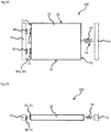
- Fig. 1A shows a schematic top view of the cover device and Fig. 1B shows a cross-sectional view of the cover device of Fig. 1A according to the present invention.
- the cover device 100 for an oven 2 comprises an intermediate connecting member 10 with a front side 11, a back side 12 and side surfaces 13, 14, wherein the side surfaces 13, 14 are configured to connect the front side 11 with the back side 12 of the intermediate connecting member 10.
- the cover device 100 further comprises a first active element 20, 21 arranged on the front side 11, wherein the first active element 20, 21 is configured to interact with a second active element 30, 31 such, that the first active element 20, 21 executes a releasable operative connection M1, M2 with the second active element 30, 31.
- the cover device 100 further comprises and a fixing element 40, 41 arranged on the back side 12 of the intermediate connecting element 10, wherein the fixing element 40, 41 is configured to execute an elastic operative connection S1, S2, and wherein a holding force of the releasable operative connection M1, M2 is weaker than a spring force of the elastic operative connection S1.
- the second active element 30, 31 can be arranged in a further first device 71.
- the first active element 20, 21 are disposed facing the second active element 30, 31.
- the fixing element 40 can be arranged in the middle of the back side 12 of the intermediate connecting member 10 and the fixing element 40 can be further connected with a further second device 72.
- the further first element 71 as well as the further second element 72 are illustrated for a better understanding of a functionality of the cover device 100.
- the further first element 71 can be an oven door 3 and the further second element 72 can be a rear wall 60 of the oven 2 (see Fig. 3A ).
- the first active element 20, 21 detaches from the second active element 30, 31 of the further second device 72 when the holding force of the releasable operative connection M1, M2 between the first active element 20, 21 and the second active element 30, 31 exceeds a predetermined value of the spring force of the elastic operative connection S1.
- the intermediate connecting member 10 of the present invention can comprise a foil, tray, sheet or shield with a heat resistant material or a combination of heat resistant materials.
- the intermediate connecting member 10 can preferably comprise the said foil, tray, sheet or shield with a flexible material or a combination of flexible materials.
- a material which can comprise both properties, namely heat resistance and flexibility can be silicone.
- each of the first active element 20, 21 and the second active element 30, 31 can comprise corresponding ferromagnetic material.
- the first active element 20, 21 can comprise a latching means and the second active element 30, 31 can comprise a counter-latching means.
- the releasable operative connection M1, M2 can be also based on a mechanical linkage, wherein the holding force can be generated between the latching means and the counter-latching means.
- the fixing element 40 can comprise a helical or coil spring.
- Fig. 1B is a cross-sectional view of the cover device 100 of Fig. 1A according to the present invention.
- Fig. 2 shows a top view of another embodiment of the cover device 100.
- Fig. 2 is based in Fig. 1A with the difference that the cover device 100 of Fig. 2 comprises two fixing elements 40, 41.
- the fixing elements 40, 41 are disposed on the back side 12 of the intermediate connecting member 10, wherein the fixing elements 40, 41 are arranged opposite to the first active elements 20, 21 and the second active elements 30, 31, respectively.
- the intermediate connecting member 10 is disposed between the first active element 20, 21 and the fixing element 40, 41, wherein the first active element 20, 21 and the fixing element 40, 41 are arranged, mounted or integrated on or with the intermediate connecting member 10.
- Figs. 3A to 3B show cross-sectional views of a oven system 300 for protecting a user against hot air and/or hot steam according to the present invention.
- Fig.3A shows a closed state of the oven system 300.
- Fig. 3B shows an intermediate state during opening the oven door 3 of the oven 2 of the oven system 300.
- Fig. 3C shows an open state of the oven system 300. That is, when the oven door 3 is fully opened or lifted-up.
- the oven system 300 for protecting a user against hot air or hot steam comprises an oven 2 with an oven door 3 configured to close or open the oven 2, wherein the oven door 3 comprises a bottom side B1 and a top side T1.
- the oven door 3 is pivotally mounted with its bottom side B1 at a front wall 63 of the oven 2 (indicated by a circle in the bottom side B1 of the oven door 3).
- the oven system 300 comprises the cover device 100 according to the present invention, wherein the second active element 30, 31 is arranged on the top side T1 of the oven door 3.
- the fixing element 40, 41 is further connected with the rear wall 60 of the oven 2 such, that the cover device 100 connects the top side T1 of the oven door 3 with the rear wall 60 of the oven 2.
- the cover device can be arranged in a receiving device 5 of the oven 2, wherein the receiving device 5 can be configured to be arranged adjacent to the top side T1 of the oven door 3. Therefore, the cover device 100 can be arranged or mounted in the oven 2 in space-saving and cost-saving manner.
- the receiving device 5 comprises the cover device 100 such, that the first active element 20, 21 of the cover device 100 and the second active element 30, 31 of the oven door 3 can be disposed facing one another in a closed state of the oven 2, for example. That is, the first active element 20, 21 and the second active element 30, 31 can also be the latching means and the counter-latching means as described above.
- the releasable operative connection M1, M2 can be also based on a mechanical linkage, wherein the holding force can be generated between the latching means and the counter-latching means.
- the receiving device 5 can comprise receiving rails 6, 7 for the cover device 100, wherein the receiving rails 6, 7 are arranged on side walls 61, 62 of the oven 2.
- the receiving rails 6, 7 can be anchored on the side walls 61, 62 of the oven.
- the receiving rails 6, 7 of the receiving device 5 can extend in a parallel direction of the longest extent of the intermediate connecting member 10. Therefore, friction between the cover device 100 and the oven 2 can be reduced.
- a sliding function can be provided based on the receiving rails 6, 7, wherein pulling out and/or pulling in the cover device can be efficiently supported.
- Fig. 3B shows the intermediate state during opening the oven door 3 of the oven 2 of the oven system 300.
- Fig 3B is based on Fig. 3A with the difference that the oven door 3 is at least partially opened of lifted-up. Therefore the cover device 100 can be at least partially pulled out of the oven 2 and oven interior, respectively, due to the holding force of the releasable operative connection M1, M2.
- the holding force of the releasable operative connection M1, M2 does not exceeds the predetermined value of the spring force of the elastic operative connection S1, S2 and the maximal spring force of the elastic operative connection S1, S2, respectively.
- the hot air or the hot steam is redirected in lateral or transversal direction due to the intermediate connecting member 10 which covers an area between the top side T1 of the oven door 3 and the front wall 63 of the oven 2.
- Fig. 3C shows an open state of the oven system 300, wherein the oven door 3 is fully opened or lifted-up.
- Fig. 3C is based on Fig. 3B with the difference that now the oven door 3 of the oven system 300 is fully opened or lifted-up.
- the cover device 100 can be pulled in inside the oven 2 and therefore in the receiving device 5 of the oven 2, respectively.
- This is based on the spring force of the elastic operative connection S1, S2, wherein the spring force is stronger than the holding force of the releasable operative connection M1, M2. Therefore, an access to the oven 2 can be in particular automatically provided and the user can be protected against burn injury caused by the hot air or the hot steam which is escaped or released when opening the oven door as illustrated in Fig. 3B .
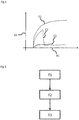
- Fig. 4 shows a graph for describing an effect of the cover device according to the present invention.
- reference sign A1 indicates the horizontal X-axis, wherein on the X-axis a time is applied.
- Reference sign A2 indicates the vertical Y-axis, wherein on the Y-axis a temperature is applied.
- Fig. 4 comprises three temperature curves C1-C3, wherein C1 illustrates a oven system without a cover device, C2 an oven system with an prior art air curtain or air curtain apparatus and C3 illustrates the oven system 300 with the cover device 100 of the present invention.
- the prior art air curtain or air curtain apparatus is not able to prevent sudden heat flow of hot air or hot steam in particular in a vertical direction or upon the user who desires access to the oven or an oven interior.
- the oven system 300 with the cover device 100 of the present invention is able to prevent sudden heat flow of hot air or hot steam in particular in a vertical direction or upon the user who desires access to the oven or an oven interior. Therefore, burn injury caused by the hot air or the hot steam released when opening the oven door can be efficiently prevented.
- Fig. 5 shows a flow diagram of an embodiment of a method for protecting the user against hot air or hot steam with the oven system according to the present invention.
- the method starts with pulling out T1 the cover device 100, when the oven door 3 is lifted up by the user.
- the method further comprises the step of detaching T2 the first active element 20, 21 from the second active element 30, 31, when the oven door 3 is substantially fully lifted up by the user.
- the method comprises pulling in T3 the cover device 100 inside the oven 2 by the spring force of the elastic operative connection S1, S2 and the fixing element 40, 41, respectively.
- the method can be based on the phenomenon, that during lifting up the oven door 3 the spring force of the elastic operative connection S1, S2 can increase and exceed the holding force of the releasable operative connection M1, M2. Consequently, the first active element 20, 21 detaches from the second active element 30, 31.
- the present invention thus provides a cover device 100 for an oven 2, in particular an electric oven.
- the cover device 100 comprises an intermediate connecting member 10 with a front side 11, a back side 12 and side surfaces 13, 14, wherein the side surfaces 13, 14 are configured to connect the front side 11 with the back side 12 of the intermediate connecting member 10.
- the cover device 100 further comprises a first active element 20, 21 arranged on the front side 11, wherein the first active element 20, 21 is configured to interact with a second active element 30, 31 such, that the first active element 20, 21 executes a releasable operative connection M1, M2 with the second active element 30, 31.
- the cover device 100 further comprises and a fixing element 40, 41 arranged on the back side 12 of the intermediate connecting element 10, wherein the fixing element 40, 41 is configured to execute an elastic operative connection S1, S2, and wherein a holding force of the releasable operative connection M1, M2 is weaker than a spring force of the elastic operative connection S1, S2.
- the present invention further provides a corresponding system and a corresponding method.
Landscapes
- Engineering & Computer Science (AREA)
- Chemical & Material Sciences (AREA)
- Combustion & Propulsion (AREA)
- Mechanical Engineering (AREA)
- General Engineering & Computer Science (AREA)
- Electric Stoves And Ranges (AREA)
Abstract
Description
- The invention relates to a cover device, an oven system for protecting a user against hot air or hot steam and a corresponding method.
- Although applicable to any system that needs a cover device to redirect hot air or hot steam produced in particular during generation of heat in an oven or cooker the present invention will mainly be described in conjunction with so called electric oven.
- Usually oven produces hot air or hot steam during a cooking process. The hot air or the hot steam mainly remains in the oven as long as the oven door is closed. Opening the oven door, in particular during the cooking process leads to a sudden escape of the hot air or hot steam in a substantially vertical direction. The temperature of the hot air or hot steam can comprise a temperature range of around 150°C to 250°C. Thus, a user has to pay attention during opening the oven door since otherwise he or she can be injured by the hot air or the hot steam.
- Document
US 7357131 B2 relates to an air curtain door system for inhibiting heat and exhaust exiting from an access opening of an oven. - Document
US 3387600 A relates to an oven with automatic air curtain means. - Accordingly, there is a need for an improved cover device for an oven, in particular an electric oven, to avoid injuries for the user.
- The present invention provides a cover device with the features of
claim 1, an oven system with the features of claim 8 and a method with the features of claim 12. - The cover device for an oven, in particular an electric oven, comprises an intermediate connecting member with a front side, a back side and side surfaces, wherein the side surfaces are configured to connect the front side with the back side of the intermediate connecting member. The cover device further comprises a first active element arranged on the front side, wherein the first active element is configured to interact with a second active element such, that the first active element executes a releasable operative connection with the second active element. The cover device further comprises and a fixing element arranged on the back side of the intermediate connecting element, wherein the fixing element is configured to execute an elastic operative connection, and wherein a holding force of the releasable operative connection is weaker than a spring force of the elastic operative connection. Alternatively also a maximal spring force of the elastic operative connection can be meant.
- The oven system for protecting a user against hot air or hot steam comprises an oven with an oven door configured to close or open the oven, wherein the oven door comprises a bottom side and a top side. To open and close the oven door, the oven door is pivotally mounted with its bottom side at a front wall of the oven. Further the oven system comprises the cover device according to the present invention or any of the here described embodiments, wherein the second active element is arranged on the top side of the oven door. Alternatively, the second active element can be mounted on or integrated in the top side of the oven door but is not limited thereof. For example, the second active element can be an integral component of the oven door, wherein a surface of the second active element can be flush with a main surface of the oven door. The here described main surface faces a front wall of the oven. The oven system comprises the fixing element of the cover device and the fixing element is connected with a rear wall of the oven such, that the cover device connects the top side of the oven door with the rear wall of the oven. For example the cover device can in particular extend parallel to a lateral extent of the oven and the cover device can be arranged in direction of a hotplate of the oven. In other words the cover device can be arranged, mounted or adjusted such that a sudden heat flow of hot air or hot steam can be prevented, when opening the oven door by a user.
- The method for protecting a user against hot air or hot steam with the oven system according to the present invention comprises the step of pulling out the cover device, when the oven door is lifted up or opened by the user. The method further comprises detaching of the first active element from the second active element, when the oven door is substantially fully lifted up or opened by the user. In Addition, the method comprises pulling in the cover device inside the oven by the spring force of the elastic operative connection and of the fixing element, respectively.
- The present invention uses the finding that it is difficult to prevent sudden heat flow of hot air or hot steam in particular in a vertical direction or upon the user who desires access to the oven or an oven interior via air circulation, air fan or an air curtain.
- The present invention therefore provides in particular an improved cover device which can be easily integrated or arranged in the oven and efficiently diverts or redirects the hot air or the hot steam in transverse, sideways or lateral direction, when opening the oven door.
- It is understood, that the term "a" comprises also a plurality of corresponding elements or components, for example, at least one or a plurality of the corresponding elements or components.
- The here and in the following described features with respect to the cover device are also disclosed for the oven system as well as the method and vice versa.
- The lateral extent of the intermediate connecting member can be substantially the same as a size of an opening of the oven interior. Therefore, the hot air or the hot steam can be efficiently diverted or redirected in the transverse, sideways or lateral direction, when opening the oven door.
- Further, a size of first active element and a size of the second active element can be the same or can be different from each other.
- The fixing element can be mechanically connected with the back side of the intermediate connecting element. The elastic operative connection can be a reversible operative connection, wherein the elastic operative connection cannot be released.
- The releasable operative connection can also be a further reversible operative connection, wherein corresponding elements - the first active element and the second active element - can be separated or detached from each other after opening the oven door by lifting up, for example.
- Further embodiments of the present invention are subject of the further subclaims and of the following description, referring to the drawings.
- In one embodiment, the first active element can be detached from the second active element when the holding force of the releasable operative connection between the first active element and the second active element exceeds a predetermined value of the spring force of the elastic operative connection. Therefore a safe and fast diversion or redirection can be realized. In addition, an access to an interior space of the oven can be easily realized since the spring force can pull in the cover device in the oven. For example the spring force is bigger than the holding force when the oven door substantially reaches its final open state or alternatively when an angle between a front wall of the oven and the tilted or lifted up oven door is bigger than 45° or 60°, for example. The predetermined value of the spring force can be determined by the Hooke's law.
- In another embodiment, the intermediate connecting member can comprise a foil, tray, sheet or shield with a heat resistant material or a combination of heat resistant materials. Therefore, the cover device can ensure high process reliability. For example, the resistant material can be an aluminum alloy, wherein aluminum can be the predominant metal. Typical alloying elements can be copper, magnesium, manganese, silicon, tin and zinc. Alternatively, the heat resistant material can comprise silicone.
- In one embodiment, the intermediate connecting member can comprise a foil, tray, sheet or shield with a flexible material or a combination of flexible materials. Therefore, the cover device can ensure high process reliability. Further, the cover device can be manufactured in space-saving manner. The intermediate connecting member can be therefore at least partially rolled up within a predetermined area of the oven for convenient storage. For example, the flexible material can be the aluminum alloy, wherein aluminum can be the predominant metal. Typical alloying elements can be copper, magnesium, manganese, silicon, tin and zinc. Alternatively, the flexible material can comprise silicone.
- In a further embodiment, each of the first active element and the second active element can comprise corresponding magnetic elements. Therefore, the releasable operative connection can be easily and cost-efficiently realized. The second active element can be arranged on a further first device, wherein the first active element and the second active element can be hold by the holding force, here magnetic holding force.
- In one embodiment, each of the first active element and the second active element can comprise corresponding ferromagnetic material. Therefore, the releasable operative connection can be permanent and sustainable and the holding force of the releasable operative connection can be constant, wherein the holding force of the releasable operative connection is weaker than the spring force of the elastic operative connection. That is, that the first active element and the second active element can be retained by magnetic attraction.
- In another embodiment, the fixing element can comprise a helical or coil spring. Therefore, the elastic operative connection can be sustainable, wherein the spring force can be increased by pulling out the cover device, in particular the intermediate connecting member. The spring force can increase until the spring force or rather the maximal spring force is stronger than the holding force. Consequently, the first active element can be detached from the second active element. The helical or the coil spring can be designed to operate with a tension load, so the said spring stretches as a load is applied to it. In other words the fixing element can be any kind of tension/extension spring.
- In one embodiment, the cover device can be arranged in a receiving device of the oven and wherein the receiving device can be configured to be arranged adjacent to the top side of the oven door. Therefore, the cover device can be arranged or mounted in the oven in space-saving and cost-saving manner. In other words the receiving device comprises the cover device such, that the first active element of the cover device and the second active element of the oven door can be disposed facing one another in a closed state of the oven, for example. That is, the first active element and the second active element can also be a latching means and a counter-latching means. Thus, the releasable operative connection can be also based on a mechanical linkage, wherein the holding force can be generated between the latching means and the counter-latching means.
- In one embodiment, the receiving device can comprise receiving rails for the cover device, wherein the receiving rails are arranged on side walls of the oven. For example, the receiving rails can be anchored on the side walls of the oven. The receiving rails of the receiving device can extend in a parallel direction of the longest extent of the intermediate connecting member. Therefore, friction between the cover device and the oven can be reduced. For example, a sliding function can be provided based on the receiving rails, wherein pulling in the cover device can be efficiently supported.
- In one embodiment, the receiving device can be configured to roll in a part of the intermediate connecting member of the cover device. Therefore a required space of the receiving device can be easily reduced. Preferably the intermediate connecting member comprises the flexible material.
- In one embodiment, during lifting up the oven door the spring force of the elastic operative connection increases and exceeds the holding force of the releasable operative connection. Therefore, an access to the oven interior can be easily provided in the open state of the oven.
- The here and in the following described features with respect to the cover device are also disclosed for the oven system as well as the method and vice versa.
- For a more complete understanding of the present invention and advantages thereof, reference is now made to the following description taken in conjunction with the accompanying drawings. The invention is explained in more detail below using exemplary embodiments, which are specified in the schematic figures of the drawings, in which:
- Figs. 1A, 1B
- show a schematic top view and a cross-sectional view of an embodiment of a cover device according to the present patent application;
- Fig. 2
- shows a top view of another embodiment of a cover device according to the present patent application;
- Figs. 3A-3C
- show cross-sectional views of an embodiment of an oven system according to the present patent application;
- Fig. 4
- shows a graph for describing an effect of the cover device according to the present patent application; and
- Fig. 5
- shows a flow diagram of an embodiment of a method according to the present patent application.
- In the figures like reference signs denote like elements unless stated otherwise.
-
Fig. 1A shows a schematic top view of the cover device andFig. 1B shows a cross-sectional view of the cover device ofFig. 1A according to the present invention. - The
cover device 100 for anoven 2, in particular an electric oven, comprises an intermediate connectingmember 10 with afront side 11, a back side 12 and side surfaces 13, 14, wherein the side surfaces 13, 14 are configured to connect thefront side 11 with the back side 12 of the intermediate connectingmember 10. Thecover device 100 further comprises a firstactive element front side 11, wherein the firstactive element active element active element active element cover device 100 further comprises and a fixingelement 40, 41 arranged on the back side 12 of the intermediate connectingelement 10, wherein the fixingelement 40, 41 is configured to execute an elastic operative connection S1, S2, and wherein a holding force of the releasable operative connection M1, M2 is weaker than a spring force of the elastic operative connection S1. - As shown in
Fig. 1A the secondactive element first device 71. The firstactive element active element - The fixing
element 40 can be arranged in the middle of the back side 12 of the intermediate connectingmember 10 and the fixingelement 40 can be further connected with a furthersecond device 72. The furtherfirst element 71 as well as the furthersecond element 72 are illustrated for a better understanding of a functionality of thecover device 100. The furtherfirst element 71 can be anoven door 3 and the furthersecond element 72 can be arear wall 60 of the oven 2 (seeFig. 3A ). - The first
active element active element second device 72 when the holding force of the releasable operative connection M1, M2 between the firstactive element active element - The intermediate connecting
member 10 of the present invention can comprise a foil, tray, sheet or shield with a heat resistant material or a combination of heat resistant materials. The intermediate connectingmember 10 can preferably comprise the said foil, tray, sheet or shield with a flexible material or a combination of flexible materials. A material which can comprise both properties, namely heat resistance and flexibility can be silicone. - For example, each of the first
active element active element active element active element - As illustrated in
Fig. 1A the fixingelement 40 can comprise a helical or coil spring. -
Fig. 1B is a cross-sectional view of thecover device 100 ofFig. 1A according to the present invention. -
Fig. 2 shows a top view of another embodiment of thecover device 100.Fig. 2 is based inFig. 1A with the difference that thecover device 100 ofFig. 2 comprises two fixingelements 40, 41. The fixingelements 40, 41 are disposed on the back side 12 of the intermediate connectingmember 10, wherein the fixingelements 40, 41 are arranged opposite to the firstactive elements active elements member 10 is disposed between the firstactive element element 40, 41, wherein the firstactive element element 40, 41 are arranged, mounted or integrated on or with the intermediate connectingmember 10. -
Figs. 3A to 3B show cross-sectional views of aoven system 300 for protecting a user against hot air and/or hot steam according to the present invention.Fig.3A shows a closed state of theoven system 300.Fig. 3B shows an intermediate state during opening theoven door 3 of theoven 2 of theoven system 300.Fig. 3C shows an open state of theoven system 300. That is, when theoven door 3 is fully opened or lifted-up. - In
Fig. 3A theoven system 300 for protecting a user against hot air or hot steam comprises anoven 2 with anoven door 3 configured to close or open theoven 2, wherein theoven door 3 comprises a bottom side B1 and a top side T1. Theoven door 3 is pivotally mounted with its bottom side B1 at afront wall 63 of the oven 2 (indicated by a circle in the bottom side B1 of the oven door 3). Further theoven system 300 comprises thecover device 100 according to the present invention, wherein the secondactive element oven door 3. The fixingelement 40, 41 is further connected with therear wall 60 of theoven 2 such, that thecover device 100 connects the top side T1 of theoven door 3 with therear wall 60 of theoven 2. - As illustrated in
Fig. 3A the cover device can be arranged in areceiving device 5 of theoven 2, wherein the receivingdevice 5 can be configured to be arranged adjacent to the top side T1 of theoven door 3. Therefore, thecover device 100 can be arranged or mounted in theoven 2 in space-saving and cost-saving manner. In other words the receivingdevice 5 comprises thecover device 100 such, that the firstactive element cover device 100 and the secondactive element oven door 3 can be disposed facing one another in a closed state of theoven 2, for example. That is, the firstactive element active element - The receiving
device 5 can comprise receiving rails 6, 7 for thecover device 100, wherein the receiving rails 6, 7 are arranged on side walls 61, 62 of theoven 2. For example, the receiving rails 6, 7 can be anchored on the side walls 61, 62 of the oven. The receiving rails 6, 7 of the receivingdevice 5 can extend in a parallel direction of the longest extent of the intermediate connectingmember 10. Therefore, friction between thecover device 100 and theoven 2 can be reduced. For example, a sliding function can be provided based on the receiving rails 6, 7, wherein pulling out and/or pulling in the cover device can be efficiently supported. -
Fig. 3B shows the intermediate state during opening theoven door 3 of theoven 2 of theoven system 300. -
Fig 3B is based onFig. 3A with the difference that theoven door 3 is at least partially opened of lifted-up. Therefore thecover device 100 can be at least partially pulled out of theoven 2 and oven interior, respectively, due to the holding force of the releasable operative connection M1, M2. In this state the holding force of the releasable operative connection M1, M2 does not exceeds the predetermined value of the spring force of the elastic operative connection S1, S2 and the maximal spring force of the elastic operative connection S1, S2, respectively. In other words, the hot air or the hot steam is redirected in lateral or transversal direction due to the intermediate connectingmember 10 which covers an area between the top side T1 of theoven door 3 and thefront wall 63 of theoven 2. -
Fig. 3C shows an open state of theoven system 300, wherein theoven door 3 is fully opened or lifted-up. -
Fig. 3C is based onFig. 3B with the difference that now theoven door 3 of theoven system 300 is fully opened or lifted-up. As illustrated inFig. 3C thecover device 100 can be pulled in inside theoven 2 and therefore in the receivingdevice 5 of theoven 2, respectively. This is based on the spring force of the elastic operative connection S1, S2, wherein the spring force is stronger than the holding force of the releasable operative connection M1, M2. Therefore, an access to theoven 2 can be in particular automatically provided and the user can be protected against burn injury caused by the hot air or the hot steam which is escaped or released when opening the oven door as illustrated inFig. 3B . -
Fig. 4 shows a graph for describing an effect of the cover device according to the present invention.
InFig. 4 reference sign A1 indicates the horizontal X-axis, wherein on the X-axis a time is applied. Reference sign A2 indicates the vertical Y-axis, wherein on the Y-axis a temperature is applied. -
Fig. 4 comprises three temperature curves C1-C3, wherein C1 illustrates a oven system without a cover device, C2 an oven system with an prior art air curtain or air curtain apparatus and C3 illustrates theoven system 300 with thecover device 100 of the present invention. - As can be seen in
Fig. 4 , the prior art air curtain or air curtain apparatus is not able to prevent sudden heat flow of hot air or hot steam in particular in a vertical direction or upon the user who desires access to the oven or an oven interior.
In contrast, theoven system 300 with thecover device 100 of the present invention is able to prevent sudden heat flow of hot air or hot steam in particular in a vertical direction or upon the user who desires access to the oven or an oven interior. Therefore, burn injury caused by the hot air or the hot steam released when opening the oven door can be efficiently prevented. -
Fig. 5 shows a flow diagram of an embodiment of a method for protecting the user against hot air or hot steam with the oven system according to the present invention. - The method starts with pulling out T1 the
cover device 100, when theoven door 3 is lifted up by the user. The method further comprises the step of detaching T2 the firstactive element active element oven door 3 is substantially fully lifted up by the user. In Addition, the method comprises pulling in T3 thecover device 100 inside theoven 2 by the spring force of the elastic operative connection S1, S2 and the fixingelement 40, 41, respectively. - The method can be based on the phenomenon, that during lifting up the
oven door 3 the spring force of the elastic operative connection S1, S2 can increase and exceed the holding force of the releasable operative connection M1, M2. Consequently, the firstactive element active element - Although specific embodiments have been illustrated and described herein, it will be appreciated by those of ordinary skill in the art that a variety of alternate and/or equivalent implementations exist. It should be appreciated that the exemplary embodiment or exemplary embodiments are only examples, and are not intended to limit the scope, applicability, or configuration in any way. Rather, the foregoing summary and detailed description will provide those skilled in the art with a convenient road map for implementing at least one exemplary embodiment, it being understood that various changes may be made in the function and arrangement of elements described in an exemplary embodiment without departing from the scope as set forth in the appended claims and their legal equivalents. Generally, this application is intended to cover any adaptations or variations of the specific embodiments discussed herein.
- The present invention thus provides a
cover device 100 for anoven 2, in particular an electric oven. Thecover device 100 comprises an intermediate connectingmember 10 with afront side 11, a back side 12 and side surfaces 13, 14, wherein the side surfaces 13, 14 are configured to connect thefront side 11 with the back side 12 of the intermediate connectingmember 10. Thecover device 100 further comprises a firstactive element front side 11, wherein the firstactive element active element active element active element cover device 100 further comprises and a fixingelement 40, 41 arranged on the back side 12 of the intermediate connectingelement 10, wherein the fixingelement 40, 41 is configured to execute an elastic operative connection S1, S2, and wherein a holding force of the releasable operative connection M1, M2 is weaker than a spring force of the elastic operative connection S1, S2. The present invention further provides a corresponding system and a corresponding method. -
- 100
- cover device
- 300
- oven system
- 2
- oven
- 3
- oven door
- 5
- receiving device of the oven
- 6, 7
- receiving rails
- 10
- intermediate connecting member
- 11
- front side of the intermediate connecting member
- 12
- back side of the intermediate connecting member
- 13, 14
- side surfaces of the intermediate connecting member
- 20, 21
- first active element
- 30, 31
- second active element
- 40, 41
- fixing element
- 60
- rear wall of the oven
- 61, 62
- side walls of the oven
- 63
- front wall of the oven
- 71
- further first device
- 72
- further second device
- B1
- bottom side of the oven door
- T1
- top side of the oven door
- M1, M2
- releasable operative connection
- S1, S2
- elastic operative connection
- C1, C2, C3
- temperature curves
- A1
- X axis
- A2
- Y axis
- T1, T2, T3
- method steps
Claims (13)
- Cover device (100) for an oven (2), in particular an electric oven, the cover device (100) comprising;
an intermediate connecting member (10) with a front side (11), a back side (12) and side surfaces (13, 14), wherein the side surfaces (13, 14) are configured to connect the front side (11) with the back side (12) of the intermediate connecting member (10),
a first active element (20, 21) arranged on the front side (11), wherein the first active element (20, 21) is configured to interact with a second active element (30, 31) such, that the first active element (20, 21) executes a releasable operative connection (M1, M2) with the second active element (30, 31), and
a fixing element (40, 41) arranged on the back side (12) of the intermediate connecting element (10), wherein the fixing element (40, 41) is configured to execute an elastic operative connection (S1, S2),
wherein a holding force of the releasable operative connection (M1, M2) is weaker than a spring force of the elastic operative connection (S1, S2). - Cover device (100) according to claim 1, wherein the first active element (20, 21) detaches from the second active element (30, 31) when the holding force of the releasable operative connection (M1, M2) between the first active element (20, 21) and the second active element (30, 31) exceeds a predetermined value of the spring force of the elastic operative connection (S1, S2).
- Cover device (100) according to any one of the preceding claims, wherein the intermediate connecting member (10) comprises a foil, tray, sheet or shield with a heat resistant material or a combination of heat resistant materials.
- Cover device (100) according to any one of the preceding claims, wherein the intermediate connecting member (10) comprises a foil, tray, sheet or shield with a flexible material or a combination of flexible materials.
- Cover device (100) according to any one of the preceding claims, wherein each of the first active element (20, 21) and the second active element (30, 31) comprises corresponding magnetic elements.
- Cover device (100) according to any one of the preceding claims, wherein each of the first active element (20, 21) and the second active element (30, 31) comprises corresponding ferromagnetic material.
- Cover device (100) according to any one of the preceding claims, wherein the fixing element (40, 41) comprises a helical or coil spring.
- Oven system (300) for protecting a user against hot air or hot steam comprising:an oven (2) with an oven door (3) configured to close or open the oven (2), wherein the oven door (3) comprises a bottom side (B1) and a top side (T1),wherein the oven door (3) is pivotally mounted with its bottom side (B1) at a front wall (63) of the oven (2), andthe cover device (100) according to any one of claims 1 to 7, wherein the second active element (30, 31) is arranged on the top side (T1) of the oven door (3), and whereinthe fixing element (40, 41) is connected with a rear wall (60) of the oven (2) such, that the cover device (100) connects the top side (T1) of the oven door (3) with the rear wall (60) of the oven (2).
- Oven system (300) according to claim 8, wherein the cover device (100) is arranged in a receiving device (5) of the oven (2) and wherein the receiving device (5) is configured to be arranged adjacent to the top side (T1) of the oven door (3).
- Oven system (300) according to claim 9, wherein the receiving device (5) comprises receiving rails (6, 7) for the cover device (100), wherein the receiving rails (6, 7) are arranged on side walls (61, 62) of the oven (2).
- Oven system (300) according to claim 9, wherein the receiving device (5) is configured to roll in a part of the intermediate connecting member (10) of the cover device (100).
- Method for protecting a user against hot air or hot steam with the oven system (300) according to any one of claims 8 to 11, the method comprising:pulling out (T1) the cover device (100) when the oven door (3) is lifted up by the user,detaching (T2) of the first active element (20, 21) from the second active element (30, 31), when the oven door (3) is substantially fully lifted up by the user, andpulling in (T3) the cover device (100) inside the oven (2) by the spring force of the elastic operative connection (S1, S2).
- Method according to claim 12, wherein during lifting up the oven door (3) the spring force of the elastic operative connection (S1, S2) increases and exceeds the holding force of the releasable operative connection (M1, M2).
Priority Applications (2)
| Application Number | Priority Date | Filing Date | Title |
|---|---|---|---|
| EP17154243.4A EP3358262B1 (en) | 2017-02-01 | 2017-02-01 | Oven system with a cover device and method |
| TR2017/02887A TR201702887A2 (en) | 2017-02-01 | 2017-02-24 | Cover device, oven system and method. |
Applications Claiming Priority (1)
| Application Number | Priority Date | Filing Date | Title |
|---|---|---|---|
| EP17154243.4A EP3358262B1 (en) | 2017-02-01 | 2017-02-01 | Oven system with a cover device and method |
Publications (2)
| Publication Number | Publication Date |
|---|---|
| EP3358262A1 true EP3358262A1 (en) | 2018-08-08 |
| EP3358262B1 EP3358262B1 (en) | 2019-12-18 |
Family
ID=57956208
Family Applications (1)
| Application Number | Title | Priority Date | Filing Date |
|---|---|---|---|
| EP17154243.4A Active EP3358262B1 (en) | 2017-02-01 | 2017-02-01 | Oven system with a cover device and method |
Country Status (2)
| Country | Link |
|---|---|
| EP (1) | EP3358262B1 (en) |
| TR (1) | TR201702887A2 (en) |
Cited By (1)
| Publication number | Priority date | Publication date | Assignee | Title |
|---|---|---|---|---|
| CN114652174A (en) * | 2020-12-22 | 2022-06-24 | 皇家飞利浦有限公司 | Cooking apparatus |
Citations (8)
| Publication number | Priority date | Publication date | Assignee | Title |
|---|---|---|---|---|
| US2526890A (en) * | 1946-01-12 | 1950-10-24 | Cribben And Sexton Company | Circulating air passage structure for ranges |
| US3132638A (en) * | 1961-07-28 | 1964-05-12 | Mullins Mfg Corp | Heat shield for built-t-in ovens |
| FR1430981A (en) * | 1965-01-15 | 1966-03-11 | Ancienne Maison Godin Soc Du F | Cooking appliance with mobile screen above an oven or broiler to protect a dashboard |
| US3387600A (en) | 1966-04-13 | 1968-06-11 | Berj A. Terzian | Oven with automatic air curtain means |
| EP0337962A1 (en) * | 1988-04-11 | 1989-10-18 | SMEG S.p.A. | Heat-guard for the control on the front panel of a cooking oven |
| EP0346306A2 (en) * | 1988-06-08 | 1989-12-13 | SMEG S.p.A. | Baffle for an automatic heat protection of the controls on the front panel of a household cooking oven |
| KR20070005427A (en) * | 2005-07-06 | 2007-01-10 | 주식회사 대우일렉트로닉스 | Cookware Adjustable Microwave |
| US7357131B2 (en) | 2004-02-19 | 2008-04-15 | Moreth Iii R Edward | Air curtain door system for an oven |
-
2017
- 2017-02-01 EP EP17154243.4A patent/EP3358262B1/en active Active
- 2017-02-24 TR TR2017/02887A patent/TR201702887A2/en unknown
Patent Citations (8)
| Publication number | Priority date | Publication date | Assignee | Title |
|---|---|---|---|---|
| US2526890A (en) * | 1946-01-12 | 1950-10-24 | Cribben And Sexton Company | Circulating air passage structure for ranges |
| US3132638A (en) * | 1961-07-28 | 1964-05-12 | Mullins Mfg Corp | Heat shield for built-t-in ovens |
| FR1430981A (en) * | 1965-01-15 | 1966-03-11 | Ancienne Maison Godin Soc Du F | Cooking appliance with mobile screen above an oven or broiler to protect a dashboard |
| US3387600A (en) | 1966-04-13 | 1968-06-11 | Berj A. Terzian | Oven with automatic air curtain means |
| EP0337962A1 (en) * | 1988-04-11 | 1989-10-18 | SMEG S.p.A. | Heat-guard for the control on the front panel of a cooking oven |
| EP0346306A2 (en) * | 1988-06-08 | 1989-12-13 | SMEG S.p.A. | Baffle for an automatic heat protection of the controls on the front panel of a household cooking oven |
| US7357131B2 (en) | 2004-02-19 | 2008-04-15 | Moreth Iii R Edward | Air curtain door system for an oven |
| KR20070005427A (en) * | 2005-07-06 | 2007-01-10 | 주식회사 대우일렉트로닉스 | Cookware Adjustable Microwave |
Cited By (1)
| Publication number | Priority date | Publication date | Assignee | Title |
|---|---|---|---|---|
| CN114652174A (en) * | 2020-12-22 | 2022-06-24 | 皇家飞利浦有限公司 | Cooking apparatus |
Also Published As
| Publication number | Publication date |
|---|---|
| EP3358262B1 (en) | 2019-12-18 |
| TR201702887A2 (en) | 2018-08-27 |
Similar Documents
| Publication | Publication Date | Title |
|---|---|---|
| EP3126561B1 (en) | Locking device for a door of a domestic appliance | |
| EP3358262B1 (en) | Oven system with a cover device and method | |
| JP5493701B2 (en) | Cooker | |
| JP6644517B2 (en) | Fuel door structure | |
| US20080024963A1 (en) | Arrangements for averting flat panel display damage | |
| CN106163330A (en) | Furniture or home appliances and for furniture or the engagement unit of home appliances | |
| US10641500B2 (en) | Shelf supporting apparatus and cooking appliance including a shelf supporting apparatus | |
| EP2359067B1 (en) | Household appliance, in particular oven | |
| JP2014045614A (en) | Pressure discharge device of enclosed type metal switch gear | |
| EP2746671B1 (en) | Cooking oven comprising a heating element fastened with fastening means | |
| JP4329728B2 (en) | Cooker | |
| EP2877785B1 (en) | A cooking device comprising a cooling fan | |
| EP1647775B1 (en) | Oven with glass supporting structure | |
| JP6751847B2 (en) | Cooker | |
| US10077906B2 (en) | Home cooking appliance with a side swing oven door having a friction hinge | |
| JP4225311B2 (en) | Induction heating cooker | |
| JP7076407B2 (en) | Cooker | |
| US20130327311A1 (en) | Stovetop cover guard | |
| US20240410594A1 (en) | Oven Vent Heat Diverter Device | |
| JP6214591B2 (en) | Cooker | |
| EP0337962A1 (en) | Heat-guard for the control on the front panel of a cooking oven | |
| KR200445166Y1 (en) | Electric Pressure Thermostat Rice Cooker | |
| CN212130238U (en) | Cooking apparatus | |
| JP6576877B2 (en) | Cooker | |
| JP2015197285A (en) | grill door |
Legal Events
| Date | Code | Title | Description |
|---|---|---|---|
| PUAI | Public reference made under article 153(3) epc to a published international application that has entered the european phase |
Free format text: ORIGINAL CODE: 0009012 |
|
| STAA | Information on the status of an ep patent application or granted ep patent |
Free format text: STATUS: THE APPLICATION HAS BEEN PUBLISHED |
|
| AK | Designated contracting states |
Kind code of ref document: A1 Designated state(s): AL AT BE BG CH CY CZ DE DK EE ES FI FR GB GR HR HU IE IS IT LI LT LU LV MC MK MT NL NO PL PT RO RS SE SI SK SM TR |
|
| AX | Request for extension of the european patent |
Extension state: BA ME |
|
| STAA | Information on the status of an ep patent application or granted ep patent |
Free format text: STATUS: REQUEST FOR EXAMINATION WAS MADE |
|
| 17P | Request for examination filed |
Effective date: 20190124 |
|
| RBV | Designated contracting states (corrected) |
Designated state(s): AL AT BE BG CH CY CZ DE DK EE ES FI FR GB GR HR HU IE IS IT LI LT LU LV MC MK MT NL NO PL PT RO RS SE SI SK SM TR |
|
| GRAP | Despatch of communication of intention to grant a patent |
Free format text: ORIGINAL CODE: EPIDOSNIGR1 |
|
| STAA | Information on the status of an ep patent application or granted ep patent |
Free format text: STATUS: GRANT OF PATENT IS INTENDED |
|
| INTG | Intention to grant announced |
Effective date: 20190711 |
|
| GRAS | Grant fee paid |
Free format text: ORIGINAL CODE: EPIDOSNIGR3 |
|
| GRAA | (expected) grant |
Free format text: ORIGINAL CODE: 0009210 |
|
| STAA | Information on the status of an ep patent application or granted ep patent |
Free format text: STATUS: THE PATENT HAS BEEN GRANTED |
|
| AK | Designated contracting states |
Kind code of ref document: B1 Designated state(s): AL AT BE BG CH CY CZ DE DK EE ES FI FR GB GR HR HU IE IS IT LI LT LU LV MC MK MT NL NO PL PT RO RS SE SI SK SM TR |
|
| REG | Reference to a national code |
Ref country code: CH Ref legal event code: EP |
|
| REG | Reference to a national code |
Ref country code: IE Ref legal event code: FG4D |
|
| REG | Reference to a national code |
Ref country code: DE Ref legal event code: R096 Ref document number: 602017009710 Country of ref document: DE |
|
| REG | Reference to a national code |
Ref country code: AT Ref legal event code: REF Ref document number: 1215034 Country of ref document: AT Kind code of ref document: T Effective date: 20200115 |
|
| REG | Reference to a national code |
Ref country code: NL Ref legal event code: MP Effective date: 20191218 |
|
| PG25 | Lapsed in a contracting state [announced via postgrant information from national office to epo] |
Ref country code: GR Free format text: LAPSE BECAUSE OF FAILURE TO SUBMIT A TRANSLATION OF THE DESCRIPTION OR TO PAY THE FEE WITHIN THE PRESCRIBED TIME-LIMIT Effective date: 20200319 Ref country code: LT Free format text: LAPSE BECAUSE OF FAILURE TO SUBMIT A TRANSLATION OF THE DESCRIPTION OR TO PAY THE FEE WITHIN THE PRESCRIBED TIME-LIMIT Effective date: 20191218 Ref country code: NO Free format text: LAPSE BECAUSE OF FAILURE TO SUBMIT A TRANSLATION OF THE DESCRIPTION OR TO PAY THE FEE WITHIN THE PRESCRIBED TIME-LIMIT Effective date: 20200318 Ref country code: LV Free format text: LAPSE BECAUSE OF FAILURE TO SUBMIT A TRANSLATION OF THE DESCRIPTION OR TO PAY THE FEE WITHIN THE PRESCRIBED TIME-LIMIT Effective date: 20191218 Ref country code: SE Free format text: LAPSE BECAUSE OF FAILURE TO SUBMIT A TRANSLATION OF THE DESCRIPTION OR TO PAY THE FEE WITHIN THE PRESCRIBED TIME-LIMIT Effective date: 20191218 Ref country code: BG Free format text: LAPSE BECAUSE OF FAILURE TO SUBMIT A TRANSLATION OF THE DESCRIPTION OR TO PAY THE FEE WITHIN THE PRESCRIBED TIME-LIMIT Effective date: 20200318 Ref country code: FI Free format text: LAPSE BECAUSE OF FAILURE TO SUBMIT A TRANSLATION OF THE DESCRIPTION OR TO PAY THE FEE WITHIN THE PRESCRIBED TIME-LIMIT Effective date: 20191218 |
|
| REG | Reference to a national code |
Ref country code: LT Ref legal event code: MG4D |
|
| PG25 | Lapsed in a contracting state [announced via postgrant information from national office to epo] |
Ref country code: RS Free format text: LAPSE BECAUSE OF FAILURE TO SUBMIT A TRANSLATION OF THE DESCRIPTION OR TO PAY THE FEE WITHIN THE PRESCRIBED TIME-LIMIT Effective date: 20191218 Ref country code: HR Free format text: LAPSE BECAUSE OF FAILURE TO SUBMIT A TRANSLATION OF THE DESCRIPTION OR TO PAY THE FEE WITHIN THE PRESCRIBED TIME-LIMIT Effective date: 20191218 |
|
| PG25 | Lapsed in a contracting state [announced via postgrant information from national office to epo] |
Ref country code: AL Free format text: LAPSE BECAUSE OF FAILURE TO SUBMIT A TRANSLATION OF THE DESCRIPTION OR TO PAY THE FEE WITHIN THE PRESCRIBED TIME-LIMIT Effective date: 20191218 |
|
| PG25 | Lapsed in a contracting state [announced via postgrant information from national office to epo] |
Ref country code: EE Free format text: LAPSE BECAUSE OF FAILURE TO SUBMIT A TRANSLATION OF THE DESCRIPTION OR TO PAY THE FEE WITHIN THE PRESCRIBED TIME-LIMIT Effective date: 20191218 Ref country code: PT Free format text: LAPSE BECAUSE OF FAILURE TO SUBMIT A TRANSLATION OF THE DESCRIPTION OR TO PAY THE FEE WITHIN THE PRESCRIBED TIME-LIMIT Effective date: 20200513 Ref country code: RO Free format text: LAPSE BECAUSE OF FAILURE TO SUBMIT A TRANSLATION OF THE DESCRIPTION OR TO PAY THE FEE WITHIN THE PRESCRIBED TIME-LIMIT Effective date: 20191218 Ref country code: CZ Free format text: LAPSE BECAUSE OF FAILURE TO SUBMIT A TRANSLATION OF THE DESCRIPTION OR TO PAY THE FEE WITHIN THE PRESCRIBED TIME-LIMIT Effective date: 20191218 Ref country code: NL Free format text: LAPSE BECAUSE OF FAILURE TO SUBMIT A TRANSLATION OF THE DESCRIPTION OR TO PAY THE FEE WITHIN THE PRESCRIBED TIME-LIMIT Effective date: 20191218 |
|
| PGFP | Annual fee paid to national office [announced via postgrant information from national office to epo] |
Ref country code: DE Payment date: 20200423 Year of fee payment: 4 |
|
| PG25 | Lapsed in a contracting state [announced via postgrant information from national office to epo] |
Ref country code: SM Free format text: LAPSE BECAUSE OF FAILURE TO SUBMIT A TRANSLATION OF THE DESCRIPTION OR TO PAY THE FEE WITHIN THE PRESCRIBED TIME-LIMIT Effective date: 20191218 Ref country code: SK Free format text: LAPSE BECAUSE OF FAILURE TO SUBMIT A TRANSLATION OF THE DESCRIPTION OR TO PAY THE FEE WITHIN THE PRESCRIBED TIME-LIMIT Effective date: 20191218 Ref country code: IS Free format text: LAPSE BECAUSE OF FAILURE TO SUBMIT A TRANSLATION OF THE DESCRIPTION OR TO PAY THE FEE WITHIN THE PRESCRIBED TIME-LIMIT Effective date: 20200418 |
|
| REG | Reference to a national code |
Ref country code: DE Ref legal event code: R097 Ref document number: 602017009710 Country of ref document: DE |
|
| REG | Reference to a national code |
Ref country code: CH Ref legal event code: PL |
|
| REG | Reference to a national code |
Ref country code: AT Ref legal event code: MK05 Ref document number: 1215034 Country of ref document: AT Kind code of ref document: T Effective date: 20191218 |
|
| PLBE | No opposition filed within time limit |
Free format text: ORIGINAL CODE: 0009261 |
|
| STAA | Information on the status of an ep patent application or granted ep patent |
Free format text: STATUS: NO OPPOSITION FILED WITHIN TIME LIMIT |
|
| REG | Reference to a national code |
Ref country code: BE Ref legal event code: MM Effective date: 20200229 |
|
| PG25 | Lapsed in a contracting state [announced via postgrant information from national office to epo] |
Ref country code: MC Free format text: LAPSE BECAUSE OF FAILURE TO SUBMIT A TRANSLATION OF THE DESCRIPTION OR TO PAY THE FEE WITHIN THE PRESCRIBED TIME-LIMIT Effective date: 20191218 Ref country code: DK Free format text: LAPSE BECAUSE OF FAILURE TO SUBMIT A TRANSLATION OF THE DESCRIPTION OR TO PAY THE FEE WITHIN THE PRESCRIBED TIME-LIMIT Effective date: 20191218 Ref country code: ES Free format text: LAPSE BECAUSE OF FAILURE TO SUBMIT A TRANSLATION OF THE DESCRIPTION OR TO PAY THE FEE WITHIN THE PRESCRIBED TIME-LIMIT Effective date: 20191218 Ref country code: LU Free format text: LAPSE BECAUSE OF NON-PAYMENT OF DUE FEES Effective date: 20200201 |
|
| 26N | No opposition filed |
Effective date: 20200921 |
|
| PG25 | Lapsed in a contracting state [announced via postgrant information from national office to epo] |
Ref country code: SI Free format text: LAPSE BECAUSE OF FAILURE TO SUBMIT A TRANSLATION OF THE DESCRIPTION OR TO PAY THE FEE WITHIN THE PRESCRIBED TIME-LIMIT Effective date: 20191218 Ref country code: LI Free format text: LAPSE BECAUSE OF NON-PAYMENT OF DUE FEES Effective date: 20200229 Ref country code: CH Free format text: LAPSE BECAUSE OF NON-PAYMENT OF DUE FEES Effective date: 20200229 Ref country code: AT Free format text: LAPSE BECAUSE OF FAILURE TO SUBMIT A TRANSLATION OF THE DESCRIPTION OR TO PAY THE FEE WITHIN THE PRESCRIBED TIME-LIMIT Effective date: 20191218 |
|
| PG25 | Lapsed in a contracting state [announced via postgrant information from national office to epo] |
Ref country code: FR Free format text: LAPSE BECAUSE OF NON-PAYMENT OF DUE FEES Effective date: 20200218 Ref country code: IE Free format text: LAPSE BECAUSE OF NON-PAYMENT OF DUE FEES Effective date: 20200201 Ref country code: IT Free format text: LAPSE BECAUSE OF FAILURE TO SUBMIT A TRANSLATION OF THE DESCRIPTION OR TO PAY THE FEE WITHIN THE PRESCRIBED TIME-LIMIT Effective date: 20191218 |
|
| PG25 | Lapsed in a contracting state [announced via postgrant information from national office to epo] |
Ref country code: PL Free format text: LAPSE BECAUSE OF FAILURE TO SUBMIT A TRANSLATION OF THE DESCRIPTION OR TO PAY THE FEE WITHIN THE PRESCRIBED TIME-LIMIT Effective date: 20191218 Ref country code: BE Free format text: LAPSE BECAUSE OF NON-PAYMENT OF DUE FEES Effective date: 20200229 |
|
| REG | Reference to a national code |
Ref country code: DE Ref legal event code: R119 Ref document number: 602017009710 Country of ref document: DE |
|
| GBPC | Gb: european patent ceased through non-payment of renewal fee |
Effective date: 20210201 |
|
| PG25 | Lapsed in a contracting state [announced via postgrant information from national office to epo] |
Ref country code: DE Free format text: LAPSE BECAUSE OF NON-PAYMENT OF DUE FEES Effective date: 20210901 Ref country code: GB Free format text: LAPSE BECAUSE OF NON-PAYMENT OF DUE FEES Effective date: 20210201 |
|
| PG25 | Lapsed in a contracting state [announced via postgrant information from national office to epo] |
Ref country code: MT Free format text: LAPSE BECAUSE OF FAILURE TO SUBMIT A TRANSLATION OF THE DESCRIPTION OR TO PAY THE FEE WITHIN THE PRESCRIBED TIME-LIMIT Effective date: 20191218 Ref country code: CY Free format text: LAPSE BECAUSE OF FAILURE TO SUBMIT A TRANSLATION OF THE DESCRIPTION OR TO PAY THE FEE WITHIN THE PRESCRIBED TIME-LIMIT Effective date: 20191218 |
|
| PG25 | Lapsed in a contracting state [announced via postgrant information from national office to epo] |
Ref country code: MK Free format text: LAPSE BECAUSE OF FAILURE TO SUBMIT A TRANSLATION OF THE DESCRIPTION OR TO PAY THE FEE WITHIN THE PRESCRIBED TIME-LIMIT Effective date: 20191218 |
|
| PGFP | Annual fee paid to national office [announced via postgrant information from national office to epo] |
Ref country code: TR Payment date: 20260130 Year of fee payment: 10 |