EP3358209A1 - Bush bearing and bearing mechanism provided therewith - Google Patents
Bush bearing and bearing mechanism provided therewith Download PDFInfo
- Publication number
- EP3358209A1 EP3358209A1 EP16851536.9A EP16851536A EP3358209A1 EP 3358209 A1 EP3358209 A1 EP 3358209A1 EP 16851536 A EP16851536 A EP 16851536A EP 3358209 A1 EP3358209 A1 EP 3358209A1
- Authority
- EP
- European Patent Office
- Prior art keywords
- axial direction
- section
- bush
- housing
- plate
- Prior art date
- Legal status (The legal status is an assumption and is not a legal conclusion. Google has not performed a legal analysis and makes no representation as to the accuracy of the status listed.)
- Granted
Links
Images



Classifications
-
- F—MECHANICAL ENGINEERING; LIGHTING; HEATING; WEAPONS; BLASTING
- F16—ENGINEERING ELEMENTS AND UNITS; GENERAL MEASURES FOR PRODUCING AND MAINTAINING EFFECTIVE FUNCTIONING OF MACHINES OR INSTALLATIONS; THERMAL INSULATION IN GENERAL
- F16C—SHAFTS; FLEXIBLE SHAFTS; ELEMENTS OR CRANKSHAFT MECHANISMS; ROTARY BODIES OTHER THAN GEARING ELEMENTS; BEARINGS
- F16C33/00—Parts of bearings; Special methods for making bearings or parts thereof
- F16C33/02—Parts of sliding-contact bearings
- F16C33/04—Brasses; Bushes; Linings
- F16C33/20—Sliding surface consisting mainly of plastics
-
- F—MECHANICAL ENGINEERING; LIGHTING; HEATING; WEAPONS; BLASTING
- F16—ENGINEERING ELEMENTS AND UNITS; GENERAL MEASURES FOR PRODUCING AND MAINTAINING EFFECTIVE FUNCTIONING OF MACHINES OR INSTALLATIONS; THERMAL INSULATION IN GENERAL
- F16C—SHAFTS; FLEXIBLE SHAFTS; ELEMENTS OR CRANKSHAFT MECHANISMS; ROTARY BODIES OTHER THAN GEARING ELEMENTS; BEARINGS
- F16C27/00—Elastic or yielding bearings or bearing supports, for exclusively rotary movement
- F16C27/06—Elastic or yielding bearings or bearing supports, for exclusively rotary movement by means of parts of rubber or like materials
- F16C27/063—Sliding contact bearings
-
- B—PERFORMING OPERATIONS; TRANSPORTING
- B62—LAND VEHICLES FOR TRAVELLING OTHERWISE THAN ON RAILS
- B62D—MOTOR VEHICLES; TRAILERS
- B62D3/00—Steering gears
- B62D3/02—Steering gears mechanical
- B62D3/12—Steering gears mechanical of rack-and-pinion type
-
- F—MECHANICAL ENGINEERING; LIGHTING; HEATING; WEAPONS; BLASTING
- F16—ENGINEERING ELEMENTS AND UNITS; GENERAL MEASURES FOR PRODUCING AND MAINTAINING EFFECTIVE FUNCTIONING OF MACHINES OR INSTALLATIONS; THERMAL INSULATION IN GENERAL
- F16C—SHAFTS; FLEXIBLE SHAFTS; ELEMENTS OR CRANKSHAFT MECHANISMS; ROTARY BODIES OTHER THAN GEARING ELEMENTS; BEARINGS
- F16C17/00—Sliding-contact bearings for exclusively rotary movement
- F16C17/02—Sliding-contact bearings for exclusively rotary movement for radial load only
-
- F—MECHANICAL ENGINEERING; LIGHTING; HEATING; WEAPONS; BLASTING
- F16—ENGINEERING ELEMENTS AND UNITS; GENERAL MEASURES FOR PRODUCING AND MAINTAINING EFFECTIVE FUNCTIONING OF MACHINES OR INSTALLATIONS; THERMAL INSULATION IN GENERAL
- F16C—SHAFTS; FLEXIBLE SHAFTS; ELEMENTS OR CRANKSHAFT MECHANISMS; ROTARY BODIES OTHER THAN GEARING ELEMENTS; BEARINGS
- F16C27/00—Elastic or yielding bearings or bearing supports, for exclusively rotary movement
- F16C27/06—Elastic or yielding bearings or bearing supports, for exclusively rotary movement by means of parts of rubber or like materials
-
- F—MECHANICAL ENGINEERING; LIGHTING; HEATING; WEAPONS; BLASTING
- F16—ENGINEERING ELEMENTS AND UNITS; GENERAL MEASURES FOR PRODUCING AND MAINTAINING EFFECTIVE FUNCTIONING OF MACHINES OR INSTALLATIONS; THERMAL INSULATION IN GENERAL
- F16C—SHAFTS; FLEXIBLE SHAFTS; ELEMENTS OR CRANKSHAFT MECHANISMS; ROTARY BODIES OTHER THAN GEARING ELEMENTS; BEARINGS
- F16C29/00—Bearings for parts moving only linearly
- F16C29/002—Elastic or yielding linear bearings or bearing supports
-
- F—MECHANICAL ENGINEERING; LIGHTING; HEATING; WEAPONS; BLASTING
- F16—ENGINEERING ELEMENTS AND UNITS; GENERAL MEASURES FOR PRODUCING AND MAINTAINING EFFECTIVE FUNCTIONING OF MACHINES OR INSTALLATIONS; THERMAL INSULATION IN GENERAL
- F16C—SHAFTS; FLEXIBLE SHAFTS; ELEMENTS OR CRANKSHAFT MECHANISMS; ROTARY BODIES OTHER THAN GEARING ELEMENTS; BEARINGS
- F16C29/00—Bearings for parts moving only linearly
- F16C29/02—Sliding-contact bearings
-
- F—MECHANICAL ENGINEERING; LIGHTING; HEATING; WEAPONS; BLASTING
- F16—ENGINEERING ELEMENTS AND UNITS; GENERAL MEASURES FOR PRODUCING AND MAINTAINING EFFECTIVE FUNCTIONING OF MACHINES OR INSTALLATIONS; THERMAL INSULATION IN GENERAL
- F16C—SHAFTS; FLEXIBLE SHAFTS; ELEMENTS OR CRANKSHAFT MECHANISMS; ROTARY BODIES OTHER THAN GEARING ELEMENTS; BEARINGS
- F16C35/00—Rigid support of bearing units; Housings, e.g. caps, covers
- F16C35/02—Rigid support of bearing units; Housings, e.g. caps, covers in the case of sliding-contact bearings
-
- F—MECHANICAL ENGINEERING; LIGHTING; HEATING; WEAPONS; BLASTING
- F16—ENGINEERING ELEMENTS AND UNITS; GENERAL MEASURES FOR PRODUCING AND MAINTAINING EFFECTIVE FUNCTIONING OF MACHINES OR INSTALLATIONS; THERMAL INSULATION IN GENERAL
- F16C—SHAFTS; FLEXIBLE SHAFTS; ELEMENTS OR CRANKSHAFT MECHANISMS; ROTARY BODIES OTHER THAN GEARING ELEMENTS; BEARINGS
- F16C2226/00—Joining parts; Fastening; Assembling or mounting parts
- F16C2226/50—Positive connections
- F16C2226/70—Positive connections with complementary interlocking parts
-
- F—MECHANICAL ENGINEERING; LIGHTING; HEATING; WEAPONS; BLASTING
- F16—ENGINEERING ELEMENTS AND UNITS; GENERAL MEASURES FOR PRODUCING AND MAINTAINING EFFECTIVE FUNCTIONING OF MACHINES OR INSTALLATIONS; THERMAL INSULATION IN GENERAL
- F16C—SHAFTS; FLEXIBLE SHAFTS; ELEMENTS OR CRANKSHAFT MECHANISMS; ROTARY BODIES OTHER THAN GEARING ELEMENTS; BEARINGS
- F16C2326/00—Articles relating to transporting
- F16C2326/20—Land vehicles
- F16C2326/24—Steering systems, e.g. steering rods or columns
-
- F—MECHANICAL ENGINEERING; LIGHTING; HEATING; WEAPONS; BLASTING
- F16—ENGINEERING ELEMENTS AND UNITS; GENERAL MEASURES FOR PRODUCING AND MAINTAINING EFFECTIVE FUNCTIONING OF MACHINES OR INSTALLATIONS; THERMAL INSULATION IN GENERAL
- F16H—GEARING
- F16H19/00—Gearings comprising essentially only toothed gears or friction members and not capable of conveying indefinitely-continuing rotary motion
- F16H19/02—Gearings comprising essentially only toothed gears or friction members and not capable of conveying indefinitely-continuing rotary motion for interconverting rotary or oscillating motion and reciprocating motion
- F16H19/04—Gearings comprising essentially only toothed gears or friction members and not capable of conveying indefinitely-continuing rotary motion for interconverting rotary or oscillating motion and reciprocating motion comprising a rack
-
- F—MECHANICAL ENGINEERING; LIGHTING; HEATING; WEAPONS; BLASTING
- F16—ENGINEERING ELEMENTS AND UNITS; GENERAL MEASURES FOR PRODUCING AND MAINTAINING EFFECTIVE FUNCTIONING OF MACHINES OR INSTALLATIONS; THERMAL INSULATION IN GENERAL
- F16H—GEARING
- F16H55/00—Elements with teeth or friction surfaces for conveying motion; Worms, pulleys or sheaves for gearing mechanisms
- F16H55/02—Toothed members; Worms
- F16H55/26—Racks
- F16H55/28—Special devices for taking up backlash
- F16H2055/281—Cylindrical or half-cylindrical bushings around the rack, e.g. using special wedges to reduce play
Definitions
- the present invention relates to a bush bearing and a bearing mechanism provided therewith.
- a bush bearing which movably supports a shaft in an axial direction thereof and a bearing mechanism provided with the bush bearing are known.
- a bush bearing which is provided between a housing and a rack shaft in a steering apparatus and which slidably supports the rack shaft is proposed (for example, refer to PTL 1).
- the bush bearing described in PTL 1 has a flange section and the bush bearing is mounted to a housing by inserting the flange section into a groove formed in the housing.
- the present invention has been made in consideration of the circumstances described above and an object thereof is to provide a bush bearing capable of suppressing the generation of abnormal noise and a bearing mechanism provided with the bush bearing.
- the present invention is provided with: a housing which has a cylindrical shape and has a fitted groove formed on an inner circumferential surface thereof; a bush bearing mounted to the inner circumferential surface of the housing; and a shaft supported by the bush bearing, wherein the bush bearing has a cylindrical bush main body, and a flange section configured to project outward from the bush main body in a radial direction thereof and to be fitted into the fitted groove, the flange section is provided with a plate-shaped section, and a protruding section configured to protrude from the plate-shaped section to one side in an axial direction of the bush main body, and has a fitting margin in the axial direction with respect to the fitted groove in the housing, a part of the flange section is configured to come into contact with a surface that forms the fitted groove in the housing and is positioned at another side in the axial direction, and the protruding section is configured to, in a state in which the plate-shaped section has elastically deformed, come into contact with
- the plate-shaped section may protrude toward an outer side of the bush main body at one end of the flange section in the axial direction, and the protruding section may protrude to the one side in the axial direction at a tip of the plate-shaped section.
- the plate-shaped section may extend along a circumferential direction of the bush main body at one end of the flange section in the axial direction, and the protruding section may protrude to the one side in the axial direction at a tip of the plate-shaped section.
- the shaft supported by the bush bearing may be a rack shaft of a steering apparatus.
- the present invention is a bush bearing provided between a housing which has a cylindrical shape and has a fitted groove formed on an inner circumferential surface thereof, and a shaft, the bush bearing including a cylindrical bush main body, and a flange section configured to project outward from the bush main body in a radial direction thereof and to be fitted into the fitted groove, wherein the flange section is provided with a plate-shaped section, and a protruding section configured to protrude from the plate-shaped section to one side in an axial direction of the bush main body, and has a fitting margin in the axial direction with respect to the fitted groove in the housing, a part of the flange section is configured to come into contact with a surface that forms the fitted groove in the housing and is positioned at another side in the axial direction, and the protruding section is configured to, in a state in which the plate-shaped section has elastically deformed, come into contact with a surface which forms the fitted groove in the housing and is positioned at the one side in the axial direction
- the plate-shaped section may protrude toward an outer side of the bush main body at one end of the flange section in the axial direction, and the protruding section may protrude to the one side in the axial direction at a tip of the plate-shaped section.
- the plate-shaped section may extend along a circumferential direction of the bush main body at one end of the flange section in the axial direction, and the protruding section may protrude to the one side in the axial direction at a tip of the plate-shaped section.
- the shaft may be a rack shaft of a steering apparatus and the bush bearing may support the rack shaft.
- a bush bearing capable of suppressing the generation of abnormal noise and a bearing mechanism provided with the bush bearing can be provided.
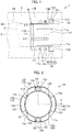
- Fig. 1 shows a sectional view taken along line I-I shown in Fig. 2 of a bush bearing 10 according to the first embodiment.
- Fig. 2 shows the bush bearing 10 as viewed from a side of a flange section 13.
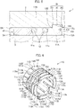
- Fig. 3 shows a perspective view of the bush bearing 10.
- Fig. 4 shows a side view of the bush bearing 10.
- Fig. 5 shows a partial enlarged view of a bearing mechanism 1 representing a state where the bush bearing 10 is mounted to a housing 2.
- the bearing mechanism 1 constitutes a part of a rack-and-pinion steering apparatus mounted to a vehicle and includes the housing 2, a rack shaft 3, and the bush bearing 10.
- the housing 2 is made of metal such as aluminum, has a cylindrical shape, and is fixed to a vehicle body (not shown).
- An annular fitted groove 2b is formed on an inner circumferential surface 2A of the housing 2 along a circumferential direction of the housing 2.
- the fitted groove 2b is constituted by a pair of annular wall surfaces 2C and 2D which are perpendicular to an axial direction X of the housing 2 and an annular circumferential wall surface 2E which extends along the circumferential direction of the housing 2.
- the rack shaft 3 has an approximately columnar shape and is provided so as to be movable along the axial direction X in the housing 2.
- a rack is provided in a part of the rack shaft 3.
- the rack is configured so as to mesh with a pinion of a pinion shaft of the steering apparatus.
- the pinion shaft is coupled to a steering wheel.
- both ends of the rack shaft 3 are coupled to wheels via a coupling mechanism (not shown).
- the bush bearing 10 includes a bush main body 11 and a plurality of (in the present embodiment, two) O rings 12.
- the bush bearing 10 is interposed between the inner circumferential surface 2A of the housing 2 and an outer circumferential surface 3A of the rack shaft 3.
- the O rings 12 have an annular shape and are constituted by an elastic material such as rubber. A section of the O rings 12 cut along a plane perpendicular to a circumferential direction of the O rings 12 has a circular shape. Each O ring 12 is inserted into an insertion groove 11c (to be described later) in a tensioned state. In addition, an outer diameter of each O ring 12 is configured to be slightly larger than the inner circumferential surface 2A of the housing 2.
- the bush main body 11 is made of resin and has a cylindrical shape. In a state where the bush bearing 10 is built into the housing 2, an axial direction of the bush main body 11 matches the axial direction X of the housing 2. An inner circumferential surface 11A of the bush main body 11 slidably supports the rack shaft 3. In addition, an inner diameter of the bush main body 11 is configured to be slightly larger than an outer diameter of the rack shaft 3, and an outer diameter of the bush main body 11 is configured to be smaller than an inner diameter of the housing 2 (refer to Fig. 1 ).
- Two insertion grooves 11c extending in a circumferential direction are formed with an interval in an axial direction on an outer circumferential surface 11B of the bush main body 11.
- Each insertion groove 11c is formed across an entire circumferential region of the outer circumferential surface 11B of the bush main body 11 and has an annular shape.
- a section of each insertion groove 11c when cut along a plane including the axial direction X of the housing 2 has a rectangular concave shape. While the number of insertion grooves 11c and the number of O rings 12 are the same, there may be more insertion grooves than O rings.
- a flange section 13 which projects toward an outer side in a radial direction of the bush main body 11 is integrally provided at one end (a right end in Fig. 1 ) of the bush main body 11 in the axial direction X.
- the flange section 13 is configured in an annular shape which is coaxial with the bush main body 11 as a whole.
- An outer diameter of the flange section 13 is configured to be larger than an inner diameter of the inner circumferential surface 2A of the housing 2 but smaller than an inner diameter of the circumferential wall surface 2D of the fitted groove 2b formed on the inner circumferential surface 2A (refer to Fig. 1 ).
- the flange section 13 is constituted by a pair of end surfaces 13A and 13B which are perpendicular to the axial direction X of the housing 2 and an outer circumferential surface 13C which extends along the circumferential direction of the housing 2.
- a plurality of (in the present embodiment, four) first slits 11e which extend toward an end surface 11D of the bush main body 11 from the end surface 13A of the flange section 13 are formed in the bush main body 11.
- the flange section 13 is divided into four sections (first to fourth flange sections 13D to 13G) by the first slits 11e. Therefore, the pair of end surfaces 13A and 13B and the outer circumferential surface 13C of the flange section 13 are also divided into four sections.
- the first slits 11e intersect each insertion groove 11c.
- a plurality of second slits 11f which extend toward the flange section 13 from the end surface 11D are formed in the bush main body 11.
- Two second slits 11f are formed at positions corresponding to the first and third flange sections 13D and 13F, and one second slit 11f is formed at positions corresponding to the second and fourth flange sections 13E and 13G.
- Each of the second slits 11f intersects each insertion groove 11c.
- Notches 13h are respectively formed in central sections of the first and third flange sections 13D and 13F in the circumferential direction. Each notch 13h is formed so as to notch the end surfaces 13A and 13B and the outer circumferential surface 13C of the flange section 13.
- a plate-shaped section 131 which protrudes outward in the radial direction from an end on the side of the end surface 13A (the one side in the axial direction X) is provided inside each notch 13h.
- a thickness of the plate-shaped section 13I in the axial direction X is configured to be extremely small with respect to a thickness (a distance between the end surface 13A and the end surface 13B) of the flange section 13 in the axial direction X.
- a protruding section 13J that protrudes to the one side in the axial direction X is provided at a tip of the plate-shaped section 13I.
- widths of the first and third flange sections 13D and 13F in the axial direction X are configured so as to be larger than a width (a distance between the wall surfaces 2C and 2D) of the fitted groove 2b of the housing 2.
- the flange section 13 has a fitting margin in the axial direction X with respect to the fitted groove 2b in the housing 2.
- the end surface 13B abuts the wall surface 2D of the fitted groove 2b
- the protruding section 13J abuts the wall surface 2C in a state where the plate-shaped section 13I has bendingly deformed (elastically deformed).
- the flange section 13 is fitted into the fitted groove 2b in the housing 2 in a state of having an elastic force in the axial direction X by the plate-shaped section 131 and the protruding section 13J.
- the O rings 12 abut the inner circumferential surface 2A of the housing 2 in a state where the bush bearing 10 is mounted to the housing 2. Furthermore, the bush main body 11 is expanded under pressure as the rack shaft 3 is inserted into the bush bearing 10, and the O rings 12 are configured so as to be compressed by the bush main body 11 and the housing 2.
- the flange section 13 is provided with: the plate-shaped section 131; and the protruding section 13J that protrudes from the plate-shaped section 131 to one side in an axial direction X, the flange section 13 has a fitting margin in the axial direction X with respect to the fitted groove 2b in the housing 2, the end surface 13B of the flange section 13 comes into contact with the wall surface 2D that forms the fitted groove 2b in the housing 2 and is positioned at another side in the axial direction X, and in a state in which the plate-shaped section 13I has elastically deformed, the protruding section 13J comes into contact with the wall surface 2C that forms the fitted groove 2b in the housing 2 and is positioned at the one side in the axial direction.
- the plate-shaped section 13I protrudes toward an outer side of the bush main body 11 (outward in a radial direction) at one end of the flange section 13 in the axial direction X, and the protruding section 13J protrudes to one side in the axial direction X at a tip of the plate-shaped section 13I.
- the flange section 13 is fitted into the fitted groove 2b in the housing 2 in a state of having an elastic force in the axial direction X by the plate-shaped section 13I and the protruding section 13J without a gap being formed between the flange section 13 and the housing 2 in the axial direction X.
- the plate-shaped section 13I and the protruding section 13J without a gap being formed between the flange section 13 and the housing 2 in the axial direction X.
- the bush bearing 10 can be readily assembled to the housing 2.
- Fig. 6 shows a perspective view of the bush bearing 110.
- Fig. 7 shows a side view of the bush bearing 110.
- Fig. 8 shows the bush bearing 10 as viewed from a side of a flange section 113.
- shapes of the first flange section 113D and the third flange section 113G differ from the shapes of the first and third flange sections 13D and 13G according to the first embodiment.
- Notches 113h are respectively formed at both ends on a side of the end surface 13A of the first and third flange sections 113D and 113F in the circumferential direction of the bush main body 11.
- Each notch 113h is formed so as to notch the end surfaces 13A and 13B and the outer circumferential surface 13C of the flange section 13 as well as the inner circumferential surface 11A of the bush main body 11.
- Each notch 113h is constituted by a first notched surface 113K which is parallel to the end surface 13A and a second notched surface 113L which is perpendicular to the first notched surface 113K.
- a plate-shaped section 113I which extends along the circumferential direction of the bush main body 11 is provided inside each notch 113h at an end on the side of the end surface 13A (the one side in the axial direction X) of the second notched surface 113L.
- a gap is formed between the plate-shaped section 113I and the first notched surface 113K.
- a protruding section 113J that protrudes to the one side in the axial direction X is provided at a tip of the plate-shaped section 113I.
- widths of the first and third flange sections 113D and 113F in the axial direction X are configured so as to be larger than a width (a distance between the wall surfaces 2C and 2D) of the fitted groove 2b in the housing 2 ( Fig. 1 ).
- the flange section 113 has a fitting margin in the axial direction X with respect to the fitted groove 2b in the housing 2.
- the end surface 13B abuts the wall surface 2D of the fitted groove 2b
- the protruding section 113J abuts the wall surface 2C in a state where the plate-shaped section 113I has bendingly deformed (elastically deformed).
- the flange section 113 is fitted into the fitted groove 2b in the housing 2 in a state of having an elastic force in the axial direction X by the plate-shaped section 113I and the protruding section 113J.
- the plate-shaped section 113I extends along a radial direction of the bush main body 11 at one end of the flange section 113 in the axial direction X, and the protruding section 113J protrudes to one side in the axial direction X at a tip of the plate-shaped section 113I.
- the flange section 113 has a fitting margin in the axial direction X with respect to the fitted groove 2b in the housing 2, and the flange section 113 is fitted into the fitted groove 2b in the housing 2 in a state of having an elastic force in the axial direction X by the plate-shaped section 113I and the protruding section 113J.
- the flange section 113 is fitted into the fitted groove 2b in the housing 2 in a state of having an elastic force in the axial direction X by the plate-shaped section 113I and the protruding section 113J without a gap being formed between the flange section 113 and the housing 2 in the axial direction X in a similar manner to the bush bearing 10 according to the first embodiment and the bearing mechanism 1 provided with the bush bearing 10.
- the bush bearing 110 is subjected to vibration, movement of the bush bearing 110 in the axial direction X can be absorbed by the elastic force. Accordingly, the generation of abnormal noise due to the flange section 113 moving in the axial direction X and colliding with the housing 2 can be suppressed.
- the bush bearing 10 can be readily assembled to the housing 2.
- the plate-shaped section 13I and the protruding section 13J are provided on the side of the end surface 13A of the flange section 13 (one side in the axial direction X) in the embodiment described above, the plate-shaped section 13I and the protruding section 13J may be provided on the side of the end surface 13B of the flange section 13 (the other side in the axial direction X) or, as shown in Fig. 9 , provided at both sides of the end surfaces 13A and 13B of the flange section 13.
- the flange section 13 is fitted into the fitted groove 2b in the housing 2 in a state of having an elastic force in the axial direction X by two plate-shaped sections 13I and two protruding sections 13J without a gap being formed between the flange section 13 and the housing 2 in the axial direction X.
- the plate-shaped section 113I and the protruding section 113J may be provided on the side of the end surface 13B of the flange section 113 (the other side in the axial direction X) or provided at both sides of the end surfaces 13A and 13B of the flange section 113.
- the directions in which the plate-shaped sections 13I and 1131 protrude or extend are not limited to the directions shown in the embodiments described above.
- the bearing mechanism 1 may be applied to an apparatus other than a steering apparatus and the bush bearings 10 and 100 may support a shaft so as to be movable in an axial direction thereof.
Landscapes
- Engineering & Computer Science (AREA)
- General Engineering & Computer Science (AREA)
- Mechanical Engineering (AREA)
- Chemical & Material Sciences (AREA)
- Combustion & Propulsion (AREA)
- Transportation (AREA)
- Support Of The Bearing (AREA)
- Mounting Of Bearings Or Others (AREA)
- Sliding-Contact Bearings (AREA)
Abstract
Description
- The present invention relates to a bush bearing and a bearing mechanism provided therewith.
- Conventionally, a bush bearing which movably supports a shaft in an axial direction thereof and a bearing mechanism provided with the bush bearing are known. For example, a bush bearing which is provided between a housing and a rack shaft in a steering apparatus and which slidably supports the rack shaft is proposed (for example, refer to PTL 1).
- The bush bearing described in
PTL 1 has a flange section and the bush bearing is mounted to a housing by inserting the flange section into a groove formed in the housing. - [PTL 1]
Japanese Patent Application Publication No.2004-347105 - However, with the configuration of the bush bearing and the housing described in
PTL 1, a gap exists between the flange section and the housing in an axial direction of the housing. Due to the gap, the bush bearing moves along the axial direction due to vibration during travel of an automobile and causes the flange section to collide with the housing, thereby generating abnormal noise. - The present invention has been made in consideration of the circumstances described above and an object thereof is to provide a bush bearing capable of suppressing the generation of abnormal noise and a bearing mechanism provided with the bush bearing.
- In order to solve the problem described above, the present invention is provided with: a housing which has a cylindrical shape and has a fitted groove formed on an inner circumferential surface thereof; a bush bearing mounted to the inner circumferential surface of the housing; and a shaft supported by the bush bearing, wherein the bush bearing has a cylindrical bush main body, and a flange section configured to project outward from the bush main body in a radial direction thereof and to be fitted into the fitted groove, the flange section is provided with a plate-shaped section, and a protruding section configured to protrude from the plate-shaped section to one side in an axial direction of the bush main body, and has a fitting margin in the axial direction with respect to the fitted groove in the housing, a part of the flange section is configured to come into contact with a surface that forms the fitted groove in the housing and is positioned at another side in the axial direction, and the protruding section is configured to, in a state in which the plate-shaped section has elastically deformed, come into contact with a surface which forms the fitted groove in the housing and is positioned at the one side in the axial direction.
- The plate-shaped section may protrude toward an outer side of the bush main body at one end of the flange section in the axial direction, and the protruding section may protrude to the one side in the axial direction at a tip of the plate-shaped section.
- In addition, the plate-shaped section may extend along a circumferential direction of the bush main body at one end of the flange section in the axial direction, and the protruding section may protrude to the one side in the axial direction at a tip of the plate-shaped section.
- Furthermore, the shaft supported by the bush bearing may be a rack shaft of a steering apparatus.
- In addition, the present invention is a bush bearing provided between a housing which has a cylindrical shape and has a fitted groove formed on an inner circumferential surface thereof, and a shaft, the bush bearing including a cylindrical bush main body, and a flange section configured to project outward from the bush main body in a radial direction thereof and to be fitted into the fitted groove, wherein the flange section is provided with a plate-shaped section, and a protruding section configured to protrude from the plate-shaped section to one side in an axial direction of the bush main body, and has a fitting margin in the axial direction with respect to the fitted groove in the housing, a part of the flange section is configured to come into contact with a surface that forms the fitted groove in the housing and is positioned at another side in the axial direction, and the protruding section is configured to, in a state in which the plate-shaped section has elastically deformed, come into contact with a surface which forms the fitted groove in the housing and is positioned at the one side in the axial direction.
- The plate-shaped section may protrude toward an outer side of the bush main body at one end of the flange section in the axial direction, and the protruding section may protrude to the one side in the axial direction at a tip of the plate-shaped section.
- In addition, the plate-shaped section may extend along a circumferential direction of the bush main body at one end of the flange section in the axial direction, and the protruding section may protrude to the one side in the axial direction at a tip of the plate-shaped section.
- Furthermore, the shaft may be a rack shaft of a steering apparatus and the bush bearing may support the rack shaft.
- According to the present invention, a bush bearing capable of suppressing the generation of abnormal noise and a bearing mechanism provided with the bush bearing can be provided.
-
- [
Fig. 1 ]
Fig. 1 shows a sectional view taken along line I-I shown inFig. 2 of a bush bearing according to a first embodiment. - [
Fig. 2 ]
Fig. 2 shows a diagram of the bush bearing according to the first embodiment as viewed from a side of a flange section. - [
Fig. 3 ]
Fig. 3 shows a perspective view of the bush bearing according to the first embodiment. - [
Fig. 4 ]
Fig. 4 shows a side view of the bush bearing according to the first embodiment. - [
Fig. 5 ]
Fig. 5 shows a partial enlarged view of a bearing mechanism representing a state where the bush bearing according to the first embodiment is mounted to a housing. - [
Fig. 6 ]
Fig. 6 shows a perspective view of a bush bearing according to a second embodiment. - [
Fig. 7 ]
Fig. 7 shows a side view of the bush bearing according to the second embodiment. - [
Fig. 8 ]
Fig. 8 shows a diagram of the bush bearing according to the second embodiment as viewed from a side of a flange section. - [
Fig. 9 ]
Fig. 9 shows an explanatory diagram of a bush bearing according to a modification. - Next, a bush bearing and a bearing mechanism provided with the bush bearing according to a first embodiment will be described with reference to the drawings. Moreover, in the present embodiment, a case where a bush bearing and a bearing mechanism provided with the bush bearing are applied to a steering apparatus will be described.
-
Fig. 1 shows a sectional view taken along line I-I shown inFig. 2 of a bush bearing 10 according to the first embodiment.Fig. 2 shows the bush bearing 10 as viewed from a side of aflange section 13.Fig. 3 shows a perspective view of the bush bearing 10.Fig. 4 shows a side view of the bush bearing 10.Fig. 5 shows a partial enlarged view of abearing mechanism 1 representing a state where the bush bearing 10 is mounted to ahousing 2. - As shown in
Fig. 1 , thebearing mechanism 1 according to the present embodiment constitutes a part of a rack-and-pinion steering apparatus mounted to a vehicle and includes thehousing 2, arack shaft 3, and the bush bearing 10. - The
housing 2 is made of metal such as aluminum, has a cylindrical shape, and is fixed to a vehicle body (not shown). An annular fittedgroove 2b is formed on an innercircumferential surface 2A of thehousing 2 along a circumferential direction of thehousing 2. The fittedgroove 2b is constituted by a pair ofannular wall surfaces housing 2 and an annularcircumferential wall surface 2E which extends along the circumferential direction of thehousing 2. - The
rack shaft 3 has an approximately columnar shape and is provided so as to be movable along the axial direction X in thehousing 2. A rack is provided in a part of therack shaft 3. The rack is configured so as to mesh with a pinion of a pinion shaft of the steering apparatus. The pinion shaft is coupled to a steering wheel. In addition, both ends of therack shaft 3 are coupled to wheels via a coupling mechanism (not shown). - As shown in
Figs. 1 to 5 , the bush bearing 10 includes a bush main body 11 and a plurality of (in the present embodiment, two)O rings 12. Thebush bearing 10 is interposed between the innercircumferential surface 2A of thehousing 2 and an outercircumferential surface 3A of therack shaft 3. - The O rings 12 have an annular shape and are constituted by an elastic material such as rubber. A section of the O rings 12 cut along a plane perpendicular to a circumferential direction of the O rings 12 has a circular shape. Each
O ring 12 is inserted into aninsertion groove 11c (to be described later) in a tensioned state. In addition, an outer diameter of eachO ring 12 is configured to be slightly larger than the innercircumferential surface 2A of thehousing 2. - The bush main body 11 is made of resin and has a cylindrical shape. In a state where the
bush bearing 10 is built into thehousing 2, an axial direction of the bush main body 11 matches the axial direction X of thehousing 2. An innercircumferential surface 11A of the bush main body 11 slidably supports therack shaft 3. In addition, an inner diameter of the bush main body 11 is configured to be slightly larger than an outer diameter of therack shaft 3, and an outer diameter of the bush main body 11 is configured to be smaller than an inner diameter of the housing 2 (refer toFig. 1 ). - Two
insertion grooves 11c extending in a circumferential direction are formed with an interval in an axial direction on an outercircumferential surface 11B of the bush main body 11. Eachinsertion groove 11c is formed across an entire circumferential region of the outercircumferential surface 11B of the bush main body 11 and has an annular shape. A section of eachinsertion groove 11c when cut along a plane including the axial direction X of thehousing 2 has a rectangular concave shape. While the number ofinsertion grooves 11c and the number of O rings 12 are the same, there may be more insertion grooves than O rings. - A
flange section 13 which projects toward an outer side in a radial direction of the bush main body 11 is integrally provided at one end (a right end inFig. 1 ) of the bush main body 11 in the axial direction X. Theflange section 13 is configured in an annular shape which is coaxial with the bush main body 11 as a whole. An outer diameter of theflange section 13 is configured to be larger than an inner diameter of the innercircumferential surface 2A of thehousing 2 but smaller than an inner diameter of thecircumferential wall surface 2D of the fittedgroove 2b formed on the innercircumferential surface 2A (refer toFig. 1 ). - The
flange section 13 is constituted by a pair ofend surfaces housing 2 and an outercircumferential surface 13C which extends along the circumferential direction of thehousing 2. - A plurality of (in the present embodiment, four)
first slits 11e which extend toward anend surface 11D of the bush main body 11 from theend surface 13A of theflange section 13 are formed in the bush main body 11. Theflange section 13 is divided into four sections (first tofourth flange sections 13D to 13G) by thefirst slits 11e. Therefore, the pair ofend surfaces circumferential surface 13C of theflange section 13 are also divided into four sections. Moreover, thefirst slits 11e intersect eachinsertion groove 11c. - A plurality of
second slits 11f which extend toward theflange section 13 from theend surface 11D are formed in the bush main body 11. Twosecond slits 11f are formed at positions corresponding to the first andthird flange sections second slit 11f is formed at positions corresponding to the second andfourth flange sections second slits 11f intersects eachinsertion groove 11c. -
Notches 13h are respectively formed in central sections of the first andthird flange sections notch 13h is formed so as to notch the end surfaces 13A and 13B and the outercircumferential surface 13C of theflange section 13. A plate-shapedsection 131 which protrudes outward in the radial direction from an end on the side of theend surface 13A (the one side in the axial direction X) is provided inside eachnotch 13h. A thickness of the plate-shapedsection 13I in the axial direction X is configured to be extremely small with respect to a thickness (a distance between theend surface 13A and theend surface 13B) of theflange section 13 in the axial direction X. A protrudingsection 13J that protrudes to the one side in the axial direction X is provided at a tip of the plate-shapedsection 13I. - Due to the protruding
section 13J, widths of the first andthird flange sections groove 2b of thehousing 2. In other words, theflange section 13 has a fitting margin in the axial direction X with respect to the fittedgroove 2b in thehousing 2. - In addition, as shown in
Fig. 5 , in a state where theflange section 13 is fitted into the fittedgroove 2b in thehousing 2, theend surface 13B abuts thewall surface 2D of the fittedgroove 2b, and the protrudingsection 13J abuts thewall surface 2C in a state where the plate-shapedsection 13I has bendingly deformed (elastically deformed). In this manner, theflange section 13 is fitted into the fittedgroove 2b in thehousing 2 in a state of having an elastic force in the axial direction X by the plate-shapedsection 131 and the protrudingsection 13J. - In addition, the O rings 12 abut the inner
circumferential surface 2A of thehousing 2 in a state where thebush bearing 10 is mounted to thehousing 2. Furthermore, the bush main body 11 is expanded under pressure as therack shaft 3 is inserted into thebush bearing 10, and the O rings 12 are configured so as to be compressed by the bush main body 11 and thehousing 2. - As described above, with the
bearing mechanism 1 according to the present embodiment, theflange section 13 is provided with: the plate-shapedsection 131; and the protrudingsection 13J that protrudes from the plate-shapedsection 131 to one side in an axial direction X, theflange section 13 has a fitting margin in the axial direction X with respect to the fittedgroove 2b in thehousing 2, theend surface 13B of theflange section 13 comes into contact with thewall surface 2D that forms the fittedgroove 2b in thehousing 2 and is positioned at another side in the axial direction X, and in a state in which the plate-shapedsection 13I has elastically deformed, the protrudingsection 13J comes into contact with thewall surface 2C that forms the fittedgroove 2b in thehousing 2 and is positioned at the one side in the axial direction. - More specifically, the plate-shaped
section 13I protrudes toward an outer side of the bush main body 11 (outward in a radial direction) at one end of theflange section 13 in the axial direction X, and the protrudingsection 13J protrudes to one side in the axial direction X at a tip of the plate-shapedsection 13I. - According to this configuration, the
flange section 13 is fitted into the fittedgroove 2b in thehousing 2 in a state of having an elastic force in the axial direction X by the plate-shapedsection 13I and the protrudingsection 13J without a gap being formed between theflange section 13 and thehousing 2 in the axial direction X. As a result, even when thebush bearing 10 is subjected to vibration, movement of the bush bearing 10 in the axial direction X can be fixed by the elastic force. Accordingly, the generation of abnormal noise due to theflange section 13 moving in the axial direction X and colliding with thehousing 2 can be suppressed. - In addition, since the
flange section 13 is fitted into the fittedgroove 2b in thehousing 2 as the plate-shapedsection 13I of theflange section 13 elastically deforms (bendingly deforms), the bush bearing 10 can be readily assembled to thehousing 2. - Next, a
bush bearing 110 according to a second embodiment and a bearing mechanism provided with thebush bearing 110 will be described with reference to the drawings. Moreover, same members as those of the bush bearing 10 according to the first embodiment will be denoted by same reference numerals and descriptions thereof will be omitted, and only different portions will be described. -
Fig. 6 shows a perspective view of thebush bearing 110.Fig. 7 shows a side view of thebush bearing 110.Fig. 8 shows the bush bearing 10 as viewed from a side of aflange section 113. - As shown in
Figs. 6 to 8 , in theflange section 113 of thebush bearing 110, among first tofourth flange sections 113D to 113G obtained by dividing theflange section 113 into four sections, shapes of thefirst flange section 113D and thethird flange section 113G differ from the shapes of the first andthird flange sections -
Notches 113h are respectively formed at both ends on a side of theend surface 13A of the first andthird flange sections notch 113h is formed so as to notch the end surfaces 13A and 13B and the outercircumferential surface 13C of theflange section 13 as well as the innercircumferential surface 11A of the bush main body 11. Eachnotch 113h is constituted by a first notchedsurface 113K which is parallel to theend surface 13A and a second notchedsurface 113L which is perpendicular to the first notchedsurface 113K. - A plate-shaped
section 113I which extends along the circumferential direction of the bush main body 11 is provided inside eachnotch 113h at an end on the side of theend surface 13A (the one side in the axial direction X) of the second notchedsurface 113L. A gap is formed between the plate-shapedsection 113I and the first notchedsurface 113K. A protrudingsection 113J that protrudes to the one side in the axial direction X is provided at a tip of the plate-shapedsection 113I. - Due to the protruding
section 113J, widths of the first andthird flange sections groove 2b in the housing 2 (Fig. 1 ). In other words, theflange section 113 has a fitting margin in the axial direction X with respect to the fittedgroove 2b in thehousing 2. - In addition, in a similar manner to the first embodiment, in a state where the
flange section 113 is fitted into the fittedgroove 2b in thehousing 2, theend surface 13B abuts thewall surface 2D of the fittedgroove 2b, and the protrudingsection 113J abuts thewall surface 2C in a state where the plate-shapedsection 113I has bendingly deformed (elastically deformed). In this manner, theflange section 113 is fitted into the fittedgroove 2b in thehousing 2 in a state of having an elastic force in the axial direction X by the plate-shapedsection 113I and the protrudingsection 113J. - As described above, the plate-shaped
section 113I extends along a radial direction of the bush main body 11 at one end of theflange section 113 in the axial direction X, and the protrudingsection 113J protrudes to one side in the axial direction X at a tip of the plate-shapedsection 113I. In addition, theflange section 113 has a fitting margin in the axial direction X with respect to the fittedgroove 2b in thehousing 2, and theflange section 113 is fitted into the fittedgroove 2b in thehousing 2 in a state of having an elastic force in the axial direction X by the plate-shapedsection 113I and the protrudingsection 113J. - According to this configuration, also in the present embodiment, the
flange section 113 is fitted into the fittedgroove 2b in thehousing 2 in a state of having an elastic force in the axial direction X by the plate-shapedsection 113I and the protrudingsection 113J without a gap being formed between theflange section 113 and thehousing 2 in the axial direction X in a similar manner to the bush bearing 10 according to the first embodiment and thebearing mechanism 1 provided with thebush bearing 10. As a result, even when thebush bearing 110 is subjected to vibration, movement of the bush bearing 110 in the axial direction X can be absorbed by the elastic force. Accordingly, the generation of abnormal noise due to theflange section 113 moving in the axial direction X and colliding with thehousing 2 can be suppressed. - In addition, since the
flange section 13 is fitted into the fittedgroove 2b in thehousing 2 as the plate-shapedsection 13I of theflange section 13 elastically deforms (bendingly deforms), the bush bearing 10 can be readily assembled to thehousing 2. - It should be noted that the present invention is not limited to the embodiments described above. Various additions, modifications, and the like of the present invention will occur to those skilled in the art without departing from the scope of the invention.
- For example, while the plate-shaped
section 13I and the protrudingsection 13J are provided on the side of theend surface 13A of the flange section 13 (one side in the axial direction X) in the embodiment described above, the plate-shapedsection 13I and the protrudingsection 13J may be provided on the side of theend surface 13B of the flange section 13 (the other side in the axial direction X) or, as shown inFig. 9 , provided at both sides of the end surfaces 13A and 13B of theflange section 13. According to this configuration, theflange section 13 is fitted into the fittedgroove 2b in thehousing 2 in a state of having an elastic force in the axial direction X by two plate-shapedsections 13I and two protrudingsections 13J without a gap being formed between theflange section 13 and thehousing 2 in the axial direction X. As a result, even when thebush bearing 10 is subjected to vibration, movement of the bush bearing 10 in the axial direction X can be absorbed by the elastic force. Accordingly, the generation of abnormal noise due to theflange section 13 moving in the axial direction X and colliding with thehousing 2 can be suppressed. Moreover, also in theflange section 113 of the bush bearing 110 according to the second embodiment, the plate-shapedsection 113I and the protrudingsection 113J may be provided on the side of theend surface 13B of the flange section 113 (the other side in the axial direction X) or provided at both sides of the end surfaces 13A and 13B of theflange section 113. - In addition, the directions in which the plate-shaped
sections - Furthermore, while cases where the
bearing mechanism 1 is applied to a steering apparatus and thebush bearings 10 and 100 support therack shaft 3 have been described in the embodiments presented above, thebearing mechanism 1 may be applied to an apparatus other than a steering apparatus and thebush bearings 10 and 100 may support a shaft so as to be movable in an axial direction thereof. -
- 1
- Bearing mechanism
- 2
- Housing
- 2A
- Inner circumferential surface
- 2b
- Fitted groove
- 2C, 2D
- Wall surface
- 3
- Rack shaft
- 10, 110
- Bush bearing
- 11
- Bush main body
- 13, 113
- Flange section
- 13I, 113I
- Plate-shaped section
- 13J, 113J
- Protruding section
Claims (8)
- A bearing mechanism, comprising:a housing which has a cylindrical shape and has a fitted groove formed on an inner circumferential surface thereof;a bush bearing mounted to the inner circumferential surface of the housing; anda shaft supported by the bush bearing, whereinthe bush bearing has a cylindrical bush main body, and a flange section configured to project outward from the bush main body in a radial direction thereof and to be fitted into the fitted groove,the flange section is provided with a plate-shaped section, and a protruding section configured to protrude from the plate-shaped section to one side in an axial direction of the bush main body, and has a fitting margin in the axial direction with respect to the fitted groove in the housing,a part of the flange section is configured to come into contact with a surface which forms the fitted groove in the housing and is positioned at another side in the axial direction, andthe protruding section is configured to, in a state in which the plate-shaped section has elastically deformed, come into contact with a surface which forms the fitted groove in the housing and is positioned at the one side in the axial direction.
- The bearing mechanism according to claim 1, wherein
the plate-shaped section is configured to protrude toward an outer side of the bush main body at one end of the flange section in the axial direction, and
the protruding section is configured to protrude to the one side in the axial direction at a tip of the plate-shaped section. - The bearing mechanism according to claim 1, wherein
the plate-shaped section is configured to extend along a circumferential direction of the bush main body at one end of the flange section in the axial direction, and
the protruding section is configured to protrude to the one side in the axial direction at a tip of the plate-shaped section. - The bearing mechanism according to any one of claims 1 to 3, wherein the shaft supported by the bush bearing is a rack shaft of a steering apparatus.
- A bush bearing provided between a housing which has a cylindrical shape and has a fitted groove formed on an inner circumferential surface thereof, and a shaft,
the bush bearing comprising:a cylindrical bush main body; anda flange section configured to project outward from the bush main body in a radial direction thereof and to be fitted into the fitted groove, whereinthe flange section is provided with a plate-shaped section, and a protruding section configured to protrude from the plate-shaped section to one side in an axial direction of the bush main body, and has a fitting margin in the axial direction with respect to the fitted groove in the housing,a part of the flange section is configured to come into contact with a surface which forms the fitted groove in the housing and is positioned at another side in the axial direction, andthe protruding section is configured to, in a state in which the plate-shaped section has elastically deformed, come into contact with a surface which forms the fitted groove in the housing and is positioned at the one side in the axial direction. - The bush bearing according to claim 4, wherein
the plate-shaped section is configured to protrude toward an outer side of the bush main body at one end of the flange section in the axial direction, and
the protruding section is configured to protrude to the one side in the axial direction at a tip of the plate-shaped section. - The bush bearing according to claim 4, wherein
the plate-shaped section is configured to extend along a circumferential direction of the bush main body at one end of the flange section in the axial direction, and
the protruding section is configured to protrude to the one side in the axial direction at a tip of the plate-shaped section. - The bush bearing according to any one of claims 5 to 7, wherein the shaft is a rack shaft of a steering apparatus, and the bush bearing supports the rack shaft.
Applications Claiming Priority (2)
| Application Number | Priority Date | Filing Date | Title |
|---|---|---|---|
| JP2015195573A JP6600522B2 (en) | 2015-10-01 | 2015-10-01 | Bush bearing and bearing mechanism including the same |
| PCT/JP2016/078464 WO2017057365A1 (en) | 2015-10-01 | 2016-09-27 | Bush bearing and bearing mechanism provided therewith |
Publications (3)
| Publication Number | Publication Date |
|---|---|
| EP3358209A1 true EP3358209A1 (en) | 2018-08-08 |
| EP3358209A4 EP3358209A4 (en) | 2019-05-22 |
| EP3358209B1 EP3358209B1 (en) | 2022-04-06 |
Family
ID=58423874
Family Applications (1)
| Application Number | Title | Priority Date | Filing Date |
|---|---|---|---|
| EP16851536.9A Active EP3358209B1 (en) | 2015-10-01 | 2016-09-27 | Bush bearing and bearing mechanism provided therewith |
Country Status (5)
| Country | Link |
|---|---|
| EP (1) | EP3358209B1 (en) |
| JP (1) | JP6600522B2 (en) |
| KR (1) | KR102606045B1 (en) |
| CN (1) | CN107850124B (en) |
| WO (1) | WO2017057365A1 (en) |
Families Citing this family (6)
| Publication number | Priority date | Publication date | Assignee | Title |
|---|---|---|---|---|
| DE112019003665T5 (en) * | 2018-07-20 | 2021-04-22 | Nsk Ltd. | Rack type steering gear unit |
| CN109340256B (en) * | 2018-11-22 | 2024-06-11 | 浙江长盛塑料轴承技术有限公司 | Linear bearing system with pretension clearance eliminating function |
| JP7324607B2 (en) | 2019-04-15 | 2023-08-10 | マツダ株式会社 | steering device |
| KR102173415B1 (en) * | 2019-06-04 | 2020-11-03 | 현대모비스 주식회사 | Rack bush of steering device for vehicle |
| KR102207576B1 (en) * | 2019-11-07 | 2021-01-26 | 현대모비스 주식회사 | Rack bush of steering device for vehicle |
| JP2023183757A (en) * | 2022-06-16 | 2023-12-28 | 株式会社ナチュラレーザ・ワン | Opening/closing support devices and office equipment |
Family Cites Families (8)
| Publication number | Priority date | Publication date | Assignee | Title |
|---|---|---|---|---|
| JPS57139724U (en) * | 1981-02-25 | 1982-09-01 | ||
| US6485180B2 (en) * | 2001-01-04 | 2002-11-26 | Delphi Technologies, Inc. | Expandable rack bushing |
| JP4657590B2 (en) | 2002-08-28 | 2011-03-23 | オイレス工業株式会社 | Sliding bearing and bearing mechanism including the same |
| JP5481777B2 (en) * | 2007-10-23 | 2014-04-23 | 株式会社ジェイテクト | Bearing mechanism with sliding bearing |
| DE102009037068A1 (en) * | 2009-08-13 | 2011-02-17 | GM Global Technology Operations, Inc., Detroit | Bearing bush in particular for a circuit housing of a vehicle and method for mounting the bearing bush |
| JP5461350B2 (en) * | 2010-09-08 | 2014-04-02 | 株式会社ショーワ | Plain bearing |
| JP5953676B2 (en) * | 2011-08-29 | 2016-07-20 | オイレス工業株式会社 | Bearing mechanism with sliding bearing |
| US9249831B2 (en) * | 2011-12-30 | 2016-02-02 | Steering Solutions Ip Holding Corporation | Bearing isolator assembly |
-
2015
- 2015-10-01 JP JP2015195573A patent/JP6600522B2/en active Active
-
2016
- 2016-09-27 KR KR1020187008458A patent/KR102606045B1/en active Active
- 2016-09-27 CN CN201680042191.5A patent/CN107850124B/en active Active
- 2016-09-27 EP EP16851536.9A patent/EP3358209B1/en active Active
- 2016-09-27 WO PCT/JP2016/078464 patent/WO2017057365A1/en not_active Ceased
Also Published As
| Publication number | Publication date |
|---|---|
| CN107850124B (en) | 2020-02-18 |
| JP2017067220A (en) | 2017-04-06 |
| KR102606045B1 (en) | 2023-11-27 |
| JP6600522B2 (en) | 2019-10-30 |
| EP3358209B1 (en) | 2022-04-06 |
| CN107850124A (en) | 2018-03-27 |
| WO2017057365A1 (en) | 2017-04-06 |
| EP3358209A4 (en) | 2019-05-22 |
| KR20180061183A (en) | 2018-06-07 |
Similar Documents
| Publication | Publication Date | Title |
|---|---|---|
| EP3358209B1 (en) | Bush bearing and bearing mechanism provided therewith | |
| US8944687B2 (en) | Radial foil bearing | |
| JP5872000B1 (en) | Coaxial connector | |
| US10243336B2 (en) | Electric wire insertion member | |
| EP2615321B1 (en) | Slide bearing | |
| US20160108750A1 (en) | Circumferential seal with seal dampening elements | |
| WO2013018505A1 (en) | Radial foil bearing | |
| US9140290B2 (en) | Self-centring cage nut | |
| US20180147886A1 (en) | Coupling system for a low-friction sealing assembly, and wheel hub unit equipped with said sealing assembly | |
| DE102017210868A1 (en) | electric motor | |
| JP6412649B2 (en) | Cable reel | |
| KR20190089070A (en) | Radial foil bearings | |
| JP2016137797A (en) | Steering device | |
| CN106133357A (en) | Bearing cage | |
| US9714681B2 (en) | High-speed snap ring and snap ring retention method | |
| JP2011089612A (en) | Cage for needle roller bearing, and needle roller bearing | |
| EP3109495A1 (en) | Roller bearing cage | |
| US20150355668A1 (en) | Control device having pull-out resistance | |
| KR20160010330A (en) | Rolling bearing and method for manufacturing such a rolling bearing | |
| EP3428471B1 (en) | Shock-absorbing stopper | |
| US20220371650A1 (en) | Electric power steering apparatus | |
| ZA202400523B (en) | Cylindrical terminal, plug-in connection structure, and method for machining cylindrical terminal | |
| JP2014088958A (en) | Cage for rolling bearing, notably for motor vehicle electric power steering bearing | |
| JP2018132115A (en) | Radial roller bearings | |
| CN108291572A (en) | The supporting arrangement of controlling cable |
Legal Events
| Date | Code | Title | Description |
|---|---|---|---|
| STAA | Information on the status of an ep patent application or granted ep patent |
Free format text: STATUS: THE INTERNATIONAL PUBLICATION HAS BEEN MADE |
|
| PUAI | Public reference made under article 153(3) epc to a published international application that has entered the european phase |
Free format text: ORIGINAL CODE: 0009012 |
|
| STAA | Information on the status of an ep patent application or granted ep patent |
Free format text: STATUS: REQUEST FOR EXAMINATION WAS MADE |
|
| 17P | Request for examination filed |
Effective date: 20180430 |
|
| AK | Designated contracting states |
Kind code of ref document: A1 Designated state(s): AL AT BE BG CH CY CZ DE DK EE ES FI FR GB GR HR HU IE IS IT LI LT LU LV MC MK MT NL NO PL PT RO RS SE SI SK SM TR |
|
| AX | Request for extension of the european patent |
Extension state: BA ME |
|
| DAV | Request for validation of the european patent (deleted) | ||
| DAX | Request for extension of the european patent (deleted) | ||
| A4 | Supplementary search report drawn up and despatched |
Effective date: 20190424 |
|
| RIC1 | Information provided on ipc code assigned before grant |
Ipc: F16H 55/28 20060101ALI20190416BHEP Ipc: B62D 3/12 20060101ALI20190416BHEP Ipc: F16C 35/02 20060101AFI20190416BHEP Ipc: F16C 27/06 20060101ALI20190416BHEP Ipc: F16H 19/04 20060101ALI20190416BHEP Ipc: F16C 17/02 20060101ALI20190416BHEP Ipc: F16C 33/20 20060101ALI20190416BHEP Ipc: F16C 29/02 20060101ALI20190416BHEP Ipc: F16C 29/00 20060101ALI20190416BHEP |
|
| STAA | Information on the status of an ep patent application or granted ep patent |
Free format text: STATUS: EXAMINATION IS IN PROGRESS |
|
| 17Q | First examination report despatched |
Effective date: 20210216 |
|
| GRAP | Despatch of communication of intention to grant a patent |
Free format text: ORIGINAL CODE: EPIDOSNIGR1 |
|
| STAA | Information on the status of an ep patent application or granted ep patent |
Free format text: STATUS: GRANT OF PATENT IS INTENDED |
|
| INTG | Intention to grant announced |
Effective date: 20211122 |
|
| GRAJ | Information related to disapproval of communication of intention to grant by the applicant or resumption of examination proceedings by the epo deleted |
Free format text: ORIGINAL CODE: EPIDOSDIGR1 |
|
| STAA | Information on the status of an ep patent application or granted ep patent |
Free format text: STATUS: EXAMINATION IS IN PROGRESS |
|
| GRAS | Grant fee paid |
Free format text: ORIGINAL CODE: EPIDOSNIGR3 |
|
| STAA | Information on the status of an ep patent application or granted ep patent |
Free format text: STATUS: GRANT OF PATENT IS INTENDED |
|
| GRAP | Despatch of communication of intention to grant a patent |
Free format text: ORIGINAL CODE: EPIDOSNIGR1 |
|
| INTC | Intention to grant announced (deleted) | ||
| RAP3 | Party data changed (applicant data changed or rights of an application transferred) |
Owner name: OILES CORPORATION |
|
| GRAA | (expected) grant |
Free format text: ORIGINAL CODE: 0009210 |
|
| STAA | Information on the status of an ep patent application or granted ep patent |
Free format text: STATUS: THE PATENT HAS BEEN GRANTED |
|
| INTG | Intention to grant announced |
Effective date: 20220222 |
|
| AK | Designated contracting states |
Kind code of ref document: B1 Designated state(s): AL AT BE BG CH CY CZ DE DK EE ES FI FR GB GR HR HU IE IS IT LI LT LU LV MC MK MT NL NO PL PT RO RS SE SI SK SM TR |
|
| REG | Reference to a national code |
Ref country code: GB Ref legal event code: FG4D |
|
| REG | Reference to a national code |
Ref country code: CH Ref legal event code: EP |
|
| REG | Reference to a national code |
Ref country code: AT Ref legal event code: REF Ref document number: 1481612 Country of ref document: AT Kind code of ref document: T Effective date: 20220415 |
|
| REG | Reference to a national code |
Ref country code: DE Ref legal event code: R096 Ref document number: 602016070895 Country of ref document: DE |
|
| REG | Reference to a national code |
Ref country code: IE Ref legal event code: FG4D |
|
| REG | Reference to a national code |
Ref country code: LT Ref legal event code: MG9D |
|
| REG | Reference to a national code |
Ref country code: NL Ref legal event code: MP Effective date: 20220406 |
|
| REG | Reference to a national code |
Ref country code: AT Ref legal event code: MK05 Ref document number: 1481612 Country of ref document: AT Kind code of ref document: T Effective date: 20220406 |
|
| PG25 | Lapsed in a contracting state [announced via postgrant information from national office to epo] |
Ref country code: NL Free format text: LAPSE BECAUSE OF FAILURE TO SUBMIT A TRANSLATION OF THE DESCRIPTION OR TO PAY THE FEE WITHIN THE PRESCRIBED TIME-LIMIT Effective date: 20220406 |
|
| PG25 | Lapsed in a contracting state [announced via postgrant information from national office to epo] |
Ref country code: SE Free format text: LAPSE BECAUSE OF FAILURE TO SUBMIT A TRANSLATION OF THE DESCRIPTION OR TO PAY THE FEE WITHIN THE PRESCRIBED TIME-LIMIT Effective date: 20220406 Ref country code: PT Free format text: LAPSE BECAUSE OF FAILURE TO SUBMIT A TRANSLATION OF THE DESCRIPTION OR TO PAY THE FEE WITHIN THE PRESCRIBED TIME-LIMIT Effective date: 20220808 Ref country code: NO Free format text: LAPSE BECAUSE OF FAILURE TO SUBMIT A TRANSLATION OF THE DESCRIPTION OR TO PAY THE FEE WITHIN THE PRESCRIBED TIME-LIMIT Effective date: 20220706 Ref country code: LT Free format text: LAPSE BECAUSE OF FAILURE TO SUBMIT A TRANSLATION OF THE DESCRIPTION OR TO PAY THE FEE WITHIN THE PRESCRIBED TIME-LIMIT Effective date: 20220406 Ref country code: HR Free format text: LAPSE BECAUSE OF FAILURE TO SUBMIT A TRANSLATION OF THE DESCRIPTION OR TO PAY THE FEE WITHIN THE PRESCRIBED TIME-LIMIT Effective date: 20220406 Ref country code: GR Free format text: LAPSE BECAUSE OF FAILURE TO SUBMIT A TRANSLATION OF THE DESCRIPTION OR TO PAY THE FEE WITHIN THE PRESCRIBED TIME-LIMIT Effective date: 20220707 Ref country code: FI Free format text: LAPSE BECAUSE OF FAILURE TO SUBMIT A TRANSLATION OF THE DESCRIPTION OR TO PAY THE FEE WITHIN THE PRESCRIBED TIME-LIMIT Effective date: 20220406 Ref country code: ES Free format text: LAPSE BECAUSE OF FAILURE TO SUBMIT A TRANSLATION OF THE DESCRIPTION OR TO PAY THE FEE WITHIN THE PRESCRIBED TIME-LIMIT Effective date: 20220406 Ref country code: BG Free format text: LAPSE BECAUSE OF FAILURE TO SUBMIT A TRANSLATION OF THE DESCRIPTION OR TO PAY THE FEE WITHIN THE PRESCRIBED TIME-LIMIT Effective date: 20220706 Ref country code: AT Free format text: LAPSE BECAUSE OF FAILURE TO SUBMIT A TRANSLATION OF THE DESCRIPTION OR TO PAY THE FEE WITHIN THE PRESCRIBED TIME-LIMIT Effective date: 20220406 |
|
| PG25 | Lapsed in a contracting state [announced via postgrant information from national office to epo] |
Ref country code: RS Free format text: LAPSE BECAUSE OF FAILURE TO SUBMIT A TRANSLATION OF THE DESCRIPTION OR TO PAY THE FEE WITHIN THE PRESCRIBED TIME-LIMIT Effective date: 20220406 Ref country code: PL Free format text: LAPSE BECAUSE OF FAILURE TO SUBMIT A TRANSLATION OF THE DESCRIPTION OR TO PAY THE FEE WITHIN THE PRESCRIBED TIME-LIMIT Effective date: 20220406 Ref country code: LV Free format text: LAPSE BECAUSE OF FAILURE TO SUBMIT A TRANSLATION OF THE DESCRIPTION OR TO PAY THE FEE WITHIN THE PRESCRIBED TIME-LIMIT Effective date: 20220406 Ref country code: IS Free format text: LAPSE BECAUSE OF FAILURE TO SUBMIT A TRANSLATION OF THE DESCRIPTION OR TO PAY THE FEE WITHIN THE PRESCRIBED TIME-LIMIT Effective date: 20220806 |
|
| REG | Reference to a national code |
Ref country code: DE Ref legal event code: R097 Ref document number: 602016070895 Country of ref document: DE |
|
| PG25 | Lapsed in a contracting state [announced via postgrant information from national office to epo] |
Ref country code: SM Free format text: LAPSE BECAUSE OF FAILURE TO SUBMIT A TRANSLATION OF THE DESCRIPTION OR TO PAY THE FEE WITHIN THE PRESCRIBED TIME-LIMIT Effective date: 20220406 Ref country code: SK Free format text: LAPSE BECAUSE OF FAILURE TO SUBMIT A TRANSLATION OF THE DESCRIPTION OR TO PAY THE FEE WITHIN THE PRESCRIBED TIME-LIMIT Effective date: 20220406 Ref country code: RO Free format text: LAPSE BECAUSE OF FAILURE TO SUBMIT A TRANSLATION OF THE DESCRIPTION OR TO PAY THE FEE WITHIN THE PRESCRIBED TIME-LIMIT Effective date: 20220406 Ref country code: EE Free format text: LAPSE BECAUSE OF FAILURE TO SUBMIT A TRANSLATION OF THE DESCRIPTION OR TO PAY THE FEE WITHIN THE PRESCRIBED TIME-LIMIT Effective date: 20220406 Ref country code: DK Free format text: LAPSE BECAUSE OF FAILURE TO SUBMIT A TRANSLATION OF THE DESCRIPTION OR TO PAY THE FEE WITHIN THE PRESCRIBED TIME-LIMIT Effective date: 20220406 Ref country code: CZ Free format text: LAPSE BECAUSE OF FAILURE TO SUBMIT A TRANSLATION OF THE DESCRIPTION OR TO PAY THE FEE WITHIN THE PRESCRIBED TIME-LIMIT Effective date: 20220406 |
|
| PLBE | No opposition filed within time limit |
Free format text: ORIGINAL CODE: 0009261 |
|
| STAA | Information on the status of an ep patent application or granted ep patent |
Free format text: STATUS: NO OPPOSITION FILED WITHIN TIME LIMIT |
|
| 26N | No opposition filed |
Effective date: 20230110 |
|
| PG25 | Lapsed in a contracting state [announced via postgrant information from national office to epo] |
Ref country code: AL Free format text: LAPSE BECAUSE OF FAILURE TO SUBMIT A TRANSLATION OF THE DESCRIPTION OR TO PAY THE FEE WITHIN THE PRESCRIBED TIME-LIMIT Effective date: 20220406 |
|
| PG25 | Lapsed in a contracting state [announced via postgrant information from national office to epo] |
Ref country code: MC Free format text: LAPSE BECAUSE OF FAILURE TO SUBMIT A TRANSLATION OF THE DESCRIPTION OR TO PAY THE FEE WITHIN THE PRESCRIBED TIME-LIMIT Effective date: 20220406 |
|
| REG | Reference to a national code |
Ref country code: CH Ref legal event code: PL |
|
| GBPC | Gb: european patent ceased through non-payment of renewal fee |
Effective date: 20220927 |
|
| REG | Reference to a national code |
Ref country code: BE Ref legal event code: MM Effective date: 20220930 |
|
| PG25 | Lapsed in a contracting state [announced via postgrant information from national office to epo] |
Ref country code: SI Free format text: LAPSE BECAUSE OF FAILURE TO SUBMIT A TRANSLATION OF THE DESCRIPTION OR TO PAY THE FEE WITHIN THE PRESCRIBED TIME-LIMIT Effective date: 20220406 |
|
| PG25 | Lapsed in a contracting state [announced via postgrant information from national office to epo] |
Ref country code: LU Free format text: LAPSE BECAUSE OF NON-PAYMENT OF DUE FEES Effective date: 20220927 |
|
| PG25 | Lapsed in a contracting state [announced via postgrant information from national office to epo] |
Ref country code: LI Free format text: LAPSE BECAUSE OF NON-PAYMENT OF DUE FEES Effective date: 20220930 Ref country code: IE Free format text: LAPSE BECAUSE OF NON-PAYMENT OF DUE FEES Effective date: 20220927 Ref country code: FR Free format text: LAPSE BECAUSE OF NON-PAYMENT OF DUE FEES Effective date: 20220930 Ref country code: CH Free format text: LAPSE BECAUSE OF NON-PAYMENT OF DUE FEES Effective date: 20220930 |
|
| PG25 | Lapsed in a contracting state [announced via postgrant information from national office to epo] |
Ref country code: BE Free format text: LAPSE BECAUSE OF NON-PAYMENT OF DUE FEES Effective date: 20220930 |
|
| PG25 | Lapsed in a contracting state [announced via postgrant information from national office to epo] |
Ref country code: GB Free format text: LAPSE BECAUSE OF NON-PAYMENT OF DUE FEES Effective date: 20220927 |
|
| PG25 | Lapsed in a contracting state [announced via postgrant information from national office to epo] |
Ref country code: IT Free format text: LAPSE BECAUSE OF FAILURE TO SUBMIT A TRANSLATION OF THE DESCRIPTION OR TO PAY THE FEE WITHIN THE PRESCRIBED TIME-LIMIT Effective date: 20220406 |
|
| PG25 | Lapsed in a contracting state [announced via postgrant information from national office to epo] |
Ref country code: HU Free format text: LAPSE BECAUSE OF FAILURE TO SUBMIT A TRANSLATION OF THE DESCRIPTION OR TO PAY THE FEE WITHIN THE PRESCRIBED TIME-LIMIT; INVALID AB INITIO Effective date: 20160927 |
|
| PG25 | Lapsed in a contracting state [announced via postgrant information from national office to epo] |
Ref country code: CY Free format text: LAPSE BECAUSE OF FAILURE TO SUBMIT A TRANSLATION OF THE DESCRIPTION OR TO PAY THE FEE WITHIN THE PRESCRIBED TIME-LIMIT Effective date: 20220406 |
|
| PG25 | Lapsed in a contracting state [announced via postgrant information from national office to epo] |
Ref country code: MK Free format text: LAPSE BECAUSE OF FAILURE TO SUBMIT A TRANSLATION OF THE DESCRIPTION OR TO PAY THE FEE WITHIN THE PRESCRIBED TIME-LIMIT Effective date: 20220406 |
|
| PG25 | Lapsed in a contracting state [announced via postgrant information from national office to epo] |
Ref country code: MT Free format text: LAPSE BECAUSE OF FAILURE TO SUBMIT A TRANSLATION OF THE DESCRIPTION OR TO PAY THE FEE WITHIN THE PRESCRIBED TIME-LIMIT Effective date: 20220406 |
|
| PG25 | Lapsed in a contracting state [announced via postgrant information from national office to epo] |
Ref country code: BG Free format text: LAPSE BECAUSE OF FAILURE TO SUBMIT A TRANSLATION OF THE DESCRIPTION OR TO PAY THE FEE WITHIN THE PRESCRIBED TIME-LIMIT Effective date: 20220406 |
|
| PG25 | Lapsed in a contracting state [announced via postgrant information from national office to epo] |
Ref country code: BG Free format text: LAPSE BECAUSE OF FAILURE TO SUBMIT A TRANSLATION OF THE DESCRIPTION OR TO PAY THE FEE WITHIN THE PRESCRIBED TIME-LIMIT Effective date: 20220406 |
|
| PGFP | Annual fee paid to national office [announced via postgrant information from national office to epo] |
Ref country code: DE Payment date: 20250805 Year of fee payment: 10 |
|
| PG25 | Lapsed in a contracting state [announced via postgrant information from national office to epo] |
Ref country code: TR Free format text: LAPSE BECAUSE OF FAILURE TO SUBMIT A TRANSLATION OF THE DESCRIPTION OR TO PAY THE FEE WITHIN THE PRESCRIBED TIME-LIMIT Effective date: 20220406 |