EP3358112B1 - An innovative door deceleration mechanism - Google Patents
An innovative door deceleration mechanism Download PDFInfo
- Publication number
- EP3358112B1 EP3358112B1 EP18150781.5A EP18150781A EP3358112B1 EP 3358112 B1 EP3358112 B1 EP 3358112B1 EP 18150781 A EP18150781 A EP 18150781A EP 3358112 B1 EP3358112 B1 EP 3358112B1
- Authority
- EP
- European Patent Office
- Prior art keywords
- arm
- door
- damping
- deceleration mechanism
- movement
- Prior art date
- Legal status (The legal status is an assumption and is not a legal conclusion. Google has not performed a legal analysis and makes no representation as to the accuracy of the status listed.)
- Active
Links
- 230000007246 mechanism Effects 0.000 title claims description 49
- 230000033001 locomotion Effects 0.000 claims description 69
- 238000013016 damping Methods 0.000 claims description 54
- 239000000463 material Substances 0.000 claims description 4
- 230000006835 compression Effects 0.000 description 5
- 238000007906 compression Methods 0.000 description 5
- 125000006850 spacer group Chemical group 0.000 description 5
- 230000006378 damage Effects 0.000 description 2
- 230000005540 biological transmission Effects 0.000 description 1
- 230000005923 long-lasting effect Effects 0.000 description 1
- 238000000034 method Methods 0.000 description 1
- 230000003068 static effect Effects 0.000 description 1
Images


Classifications
-
- E—FIXED CONSTRUCTIONS
- E05—LOCKS; KEYS; WINDOW OR DOOR FITTINGS; SAFES
- E05D—HINGES OR SUSPENSION DEVICES FOR DOORS, WINDOWS OR WINGS
- E05D3/00—Hinges with pins
- E05D3/06—Hinges with pins with two or more pins
- E05D3/16—Hinges with pins with two or more pins with seven parallel pins and four arms
-
- E—FIXED CONSTRUCTIONS
- E05—LOCKS; KEYS; WINDOW OR DOOR FITTINGS; SAFES
- E05F—DEVICES FOR MOVING WINGS INTO OPEN OR CLOSED POSITION; CHECKS FOR WINGS; WING FITTINGS NOT OTHERWISE PROVIDED FOR, CONCERNED WITH THE FUNCTIONING OF THE WING
- E05F5/00—Braking devices, e.g. checks; Stops; Buffers
- E05F5/02—Braking devices, e.g. checks; Stops; Buffers specially for preventing the slamming of swinging wings during final closing movement, e.g. jamb stops
-
- E—FIXED CONSTRUCTIONS
- E05—LOCKS; KEYS; WINDOW OR DOOR FITTINGS; SAFES
- E05Y—INDEXING SCHEME ASSOCIATED WITH SUBCLASSES E05D AND E05F, RELATING TO CONSTRUCTION ELEMENTS, ELECTRIC CONTROL, POWER SUPPLY, POWER SIGNAL OR TRANSMISSION, USER INTERFACES, MOUNTING OR COUPLING, DETAILS, ACCESSORIES, AUXILIARY OPERATIONS NOT OTHERWISE PROVIDED FOR, APPLICATION THEREOF
- E05Y2201/00—Constructional elements; Accessories therefor
- E05Y2201/20—Brakes; Disengaging means; Holders; Stops; Valves; Accessories therefor
- E05Y2201/21—Brakes
-
- E—FIXED CONSTRUCTIONS
- E05—LOCKS; KEYS; WINDOW OR DOOR FITTINGS; SAFES
- E05Y—INDEXING SCHEME ASSOCIATED WITH SUBCLASSES E05D AND E05F, RELATING TO CONSTRUCTION ELEMENTS, ELECTRIC CONTROL, POWER SUPPLY, POWER SIGNAL OR TRANSMISSION, USER INTERFACES, MOUNTING OR COUPLING, DETAILS, ACCESSORIES, AUXILIARY OPERATIONS NOT OTHERWISE PROVIDED FOR, APPLICATION THEREOF
- E05Y2900/00—Application of doors, windows, wings or fittings thereof
- E05Y2900/30—Application of doors, windows, wings or fittings thereof for domestic appliances
- E05Y2900/302—Application of doors, windows, wings or fittings thereof for domestic appliances for built-in appliances
-
- E—FIXED CONSTRUCTIONS
- E05—LOCKS; KEYS; WINDOW OR DOOR FITTINGS; SAFES
- E05Y—INDEXING SCHEME ASSOCIATED WITH SUBCLASSES E05D AND E05F, RELATING TO CONSTRUCTION ELEMENTS, ELECTRIC CONTROL, POWER SUPPLY, POWER SIGNAL OR TRANSMISSION, USER INTERFACES, MOUNTING OR COUPLING, DETAILS, ACCESSORIES, AUXILIARY OPERATIONS NOT OTHERWISE PROVIDED FOR, APPLICATION THEREOF
- E05Y2900/00—Application of doors, windows, wings or fittings thereof
- E05Y2900/30—Application of doors, windows, wings or fittings thereof for domestic appliances
- E05Y2900/31—Application of doors, windows, wings or fittings thereof for domestic appliances for refrigerators
Definitions
- the present invention relates to an innovative door deceleration mechanism which prevents the doors from closing too fast in built-in fridges and similar household appliances, and which elongates their operating life.
- the doors placed on the volume to be used especially in built-in household appliances and similar devices differ according to their opening directions.
- the doors in built-in household appliances perform upward or horizontal opening movement.
- the door completes the closing movement by performing rotary movement centered around its edge on which it is connected with the pushing force applied by the user or the weight force of the door.
- the door hits on the body rapidly in closing movements realized with weight force of the door or the force of the user.
- the door can be deformed upon the door hitting harshly on the body, and there can be serious injuries if the limb of the user is left under the door.
- heat transfer may increase between the outer environment and inside the inner volume of the appliance as a result of opening the door after it is closed, and this situation negatively affects the operation of the appliance.
- a force should be applied on the appliance body for keeping the door closed after it is closed.
- the United States patent document no. US2010101052 discloses a hinge mechanism with multiple connections.
- the inventive multiple connection hinge comprises a fixing member, and a rotatable door shaft bearing is attached movably relative to the fixing member.
- a spring placed between the fixing member and the door shaft bearing applies pre-tension to the door shaft bearing while the door is in closed position.
- the inventive multiple connection hinge mechanism can especially be applied to the fridge doors in order to prevent hitting.
- Patent document no. DE29918559 U1 discloses a wide-angle hinge, in particular for furniture, wherein a body-side hinge part side and a wing fixed to one another by a plurality of pivot tabs, is accessible to an angle of substantially greater than 90 °, wherein the usable angle is reduced by a spacer, the spacer element is U-shaped profile in cross section and that the lateral legs of the U-shaped spacer with parallel or substantially parallel to the central web slots extending are provided and that the spacer in its width to a serial link is pushed, in the inserted state with the wider area the articulated lever in the longitudinal slot of the lateral legs of the spacer engages.
- the objective of the present invention is to provide an innovative and long-lasting door deceleration mechanism which enables the doors of the household appliances such as built-in fridge and like to be closed by decelerating.
- the objective of the present invention is to provide an innovative door deceleration mechanism which enables the doors of the household appliances such as built-in fridge and like to be closed by decelerating without using spring member.
- the objective of the present invention is to provide an innovative door deceleration mechanism wherein damping mechanism is used for closing doors of the household appliances such as built-in fridge and like by decelerating.
- Another objective of the present invention is to provide an innovative door deceleration mechanism which comprises several precautions against damages that can occur due to internal and external forces and which provides long operating time.
- a door deceleration mechanism (1) which prevents the doors especially in built-in fridges and the like from closing too fast, essentially comprises
- the inventive door deceleration mechanism (1) is in form of five arms which enable the loads originating from door weight and the internal parts of the hinge to be distributed and a slow closing movement to be realized.
- the distribution of the loads increases the static and dynamic strength of the mechanism and also increases its operating life.
- the door deceleration mechanism (1) is comprised of an upper bracket (3) fixed on the door, a fixed bracket (2) fixed on the body on which the door will be closed, a first arm (4), a second arm (5) and a third arm (6) enabling the door to realize opening and closing movements by making folding movement, a guide arm (7) preventing the door from closing too fast, and a damping arm (8).
- the fixed bracket (2) is provided fixed on the body on which the door will be closed.
- the five arm mechanisms are provided between the fixed bracket (2) and the upper bracket (3).
- the first arm (4) provided on the fixed bracket (2) makes rotary movement centered around the connection point of the fixed bracket (2).
- the second arm (5) and the third arm (6) provided between the first arm (4) and the upper bracket (3) realize a folding movement together with the first arm (4) in opening and closing movement of the door.
- There is a guide arm (7) which enables the first arm (4), second arm (5) and the third arm (6) to move in desired closing and opening directions in opening and closing movements of the door.
- the guide arm (7) makes rotary movement on the fixed bracket (2) to which it is connected in opening movement of the door, and enables the third arm (6) to which it is connected and thus the first arm (4) and the second arm (5) to move in a certain direction.
- the damping arm (8) is attached on the third arm (6) from one side such that it can rotate freely, and it is attached on the second arm (5) from the other side.
- the damping arm (8) has a slot (81) in form of a channel the connection of which to the second arm (5) passes onto a pin (51) and which can move on the fixed pin (51). It transfers the loads that come during closing of the door on to the body on which the door closes through the fixed bracket (2).
- the damping arm (8) makes rotary motion on the third arm (6) to which it is connected, and the slot (81) provided on its other end moves on the fixed pin (51).
- the movement of the fixed pin (51) inside the slot (81) continues until closing movement comes to the position where it is wanted to be slowed down.
- the pin (51) contacts around the slot (81) when the closing movement comes to the level where it is desired to be slowed down, and the slot (81) is prevented from moving in direction of the fixed pin (51).
- the damping arm (8) realizes a flexing movement.
- the damping arm (8) provided between the second arm (5) and the third arm (6) slows down the movement of the second arm (5) and the third arm (6), and enables the door to complete its closing movement slowly.
- the guide arm (7) and the damping arm (8) are manufactured from a flexible material.
- the guide arm (7) and the damping arm (8) become more suitable for absorbing the loads coming thereon thanks to being manufactured from a flexible material, they return to initial positions and forms upon lifting the loads.
- the guide arm (7) and the damping arm (8) are manufactured from a plastic material.
- damping system (9) which is activated during closing movement of the door.
- the said damping system (9) essentially comprises
- the damping system (9) essentially transfers the force it receives from the guide arm (7) on the force damper (92) with a rotary movement depending on the cam form of the bump (71), and thus decelerates the door.
- the guide arm (7) starts to make rotary motion centered around the fixed bracket (2).
- the bump (71) provided on the guide arm (7) contacts the first extension (911) provided on the connection piece (91), and transfers the closing force of the door to the first extension (911).
- the force coming on the first extension drives the connection piece (91) for rotating around its own axis, and it is transferred to the force damper (92) through the second extension (912) provided on the connection piece (91).
- the loads generated due to inertial moment of the door are enabled to be transferred to the damping system (9) first by the guide arm (7) in a certain angular position and depending on the cam form provided on top of the bump (71), and then to the fixed bracket (2) by the damping system (9).
- the guide arm (7) transfers the loads coming during closing of the door to the fixed bracket (2) through the damping system (9) depending on the cam form (71). These loads are transferred on the body on which the door is closed by means of the fixed bracket (2).
- the excessive loads that can occur due to closing the door faster than required are absorbed by the guide arm (7) flexing in opposite direction relative to the cam form (71), and the piston (92) provided on the damping system (9) is prevented from being deformed due to excessive loads.
- the force damper (92) is a piston. In this way, the forces coming on the connection piece (91) are absorbed with a piston, and the door is enabled to close slowly.
- the force damper (92) is a spring. In this way, the forces coming on the connection piece (91) are absorbed with a spring, and the door is enabled to close slowly.
- the guide arm (7) is flexible. In excessive loads that can occur in case the door is closed too fast, the guide arm makes flexing movement in opposite direction of the incoming force and absorbs the force, and thus the force damping (92) piece is prevented from being deformed under excessive loads.
- damping system (9) is used together with slowing down of the damping arm (8), it is activated in case an excessive load comes on the door in closing direction.
- the damping system (9) is used instead of spring, and it realizes the slow closing movement of the door all by itself.
- the guide arm (7) and the damping arm (8) are connected on the third arm (6) such that they will rotate freely on the same shaft. In this way, both guide arm (7) and the damping arm (8) can realize rotary motion centered around a single shaft by means of using a single shaft.
- damping arm (8) which is connected on the third arm (6) from one side such that it will freely rotate, and which is connected on the second arm (5) from its other end upon the pin (51) passing inside a linear channel shaped slot (81) provided thereon, which slows down the closing movement of the door by means of a rotary movement centered around the third arm (6) during closing movement of the door and a flexing movement after the movement of the slot (81) towards the pin (51) ends, the flexing movement of which continues up to a certain angular position, which transfers force to the second arm (5) and the third arm (6) to which it is connected due to the flexing movement it performs in closed position of the door, and which helps the door to remain in closed position by means of the force it transfers.
- damping arm (8) which is connected on the third arm (3) from one side such that it can rotate freely and to the second arm (5) by the pin (51) passing inside a linear channel shaped slot (81) provided thereon from the other side, which makes rotary motion centered around the third arm (6) during the opening movement of the door, and which preserves its current form due to the movement of the slot (81) towards the pin (51), and therefore which is not subjected to any elastic-plastic deformation, fatigue during opening movement of the door.
Landscapes
- Engineering & Computer Science (AREA)
- Mechanical Engineering (AREA)
- Closing And Opening Devices For Wings, And Checks For Wings (AREA)
- Refrigerator Housings (AREA)
Description
- The present invention relates to an innovative door deceleration mechanism which prevents the doors from closing too fast in built-in fridges and similar household appliances, and which elongates their operating life.
- The doors placed on the volume to be used especially in built-in household appliances and similar devices differ according to their opening directions. The doors in built-in household appliances (fridge, oven, etc.) perform upward or horizontal opening movement. The door completes the closing movement by performing rotary movement centered around its edge on which it is connected with the pushing force applied by the user or the weight force of the door. The door hits on the body rapidly in closing movements realized with weight force of the door or the force of the user. The door can be deformed upon the door hitting harshly on the body, and there can be serious injuries if the limb of the user is left under the door. Furthermore, heat transfer may increase between the outer environment and inside the inner volume of the appliance as a result of opening the door after it is closed, and this situation negatively affects the operation of the appliance. A force should be applied on the appliance body for keeping the door closed after it is closed.
- In the background art, there are various spring mechanisms in order to prevent the door from hitting hardly on the body on which it is to be closed and enable the door to remain closed on the appliance body. The moment occurring due to the weight of the door or the user applying force in closing direction of the door is enabled to be absorbed on the spring, and thus the door is enabled to be closed slowly. However, its desired absorbing ratio with desired angular position could not be determined; a solution for protecting with an additional elastic member against excess loads could not be provided. Furthermore, in systems wherein the door is enabled to be closed slowly with a spring, the compression spring used for force generation is installed in all angular positions during closing and opening of the door, and it is continuously subjected to internal tension. In open positions of the door wherein force-moment generation for closing the door is not required, the installed position of the spring, its internal tension continues. This situation causes an unnecessary fatigue on the spring, and then it negatively affects the life of the spring; and this creates the risk of the mechanism losing its function completely as a result of the deformation that can occur in the spring. Furthermore, in spring door mechanism used in the current technique, a plurality of intermediate members (the parts on which two ends of the compression spring abuts, structural members preventing the compression spring from shifting left and right, transmission components to which the compression spring transfers force, cam forms, etc.) are required so that the position of the compression spring is maintained stably and it generates the necessary forces in the required ratio and transfers in the desired direction. The presence of the said intermediate members takes up space in limited volume inside the mechanism, and this creates a negative situation in terms of cost.
- The United States patent document no.
US2010101052 , an application in the state of the art, discloses a hinge mechanism with multiple connections. The inventive multiple connection hinge comprises a fixing member, and a rotatable door shaft bearing is attached movably relative to the fixing member. A spring placed between the fixing member and the door shaft bearing applies pre-tension to the door shaft bearing while the door is in closed position. The inventive multiple connection hinge mechanism can especially be applied to the fridge doors in order to prevent hitting. -
Patent document no. DE29918559 U1 discloses a wide-angle hinge, in particular for furniture, wherein a body-side hinge part side and a wing fixed to one another by a plurality of pivot tabs, is accessible to an angle of substantially greater than 90 °, wherein the usable angle is reduced by a spacer, the spacer element is U-shaped profile in cross section and that the lateral legs of the U-shaped spacer with parallel or substantially parallel to the central web slots extending are provided and that the spacer in its width to a serial link is pushed, in the inserted state with the wider area the articulated lever in the longitudinal slot of the lateral legs of the spacer engages. - The objective of the present invention is to provide an innovative and long-lasting door deceleration mechanism which enables the doors of the household appliances such as built-in fridge and like to be closed by decelerating.
- The objective of the present invention is to provide an innovative door deceleration mechanism which enables the doors of the household appliances such as built-in fridge and like to be closed by decelerating without using spring member.
- The objective of the present invention is to provide an innovative door deceleration mechanism wherein damping mechanism is used for closing doors of the household appliances such as built-in fridge and like by decelerating.
- Another objective of the present invention is to provide an innovative door deceleration mechanism which comprises several precautions against damages that can occur due to internal and external forces and which provides long operating time.
- An innovative door deceleration mechanism developed to fulfill the objective of the present invention is illustrated in the accompanying figures wherein:
-
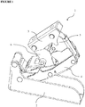
Figure 1 is the front perspective view of the inventive innovative door deceleration mechanism. -
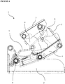
Figure 2 is the front perspective view of the inventive innovative door deceleration mechanism when the door is in open position. -
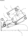
Figure 3 is the front view of the inventive innovative door deceleration mechanism. -
Figure 4 is the front view of the inventive innovative door deceleration mechanism in the closing position of the door. -
Figure 5 is the front detailed view of the damping arm and pin in the inventive innovative door deceleration mechanism. -
Figure 6 is the front detailed view of the inventive innovative door deceleration mechanism in the closing position of the door. -
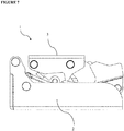
Figure 7 is the front view of the inventive innovative door deceleration mechanism in closed position of the door. -
Figure 8 is the front perspective view of the guide arm present in the inventive innovative door deceleration mechanism. -
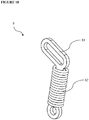
Figure 9 is the front perspective view of the damping arm present in the inventive innovative door deceleration mechanism. -
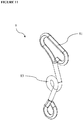
Figure 10 is the front perspective view of another version of the damping arm present in the inventive innovative door deceleration mechanism. -
Figure 11 is the front perspective view of another version of the damping arm present in the inventive innovative door deceleration mechanism. -
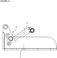
Figure 12 is the front perspective view of the piston mechanism present in the inventive innovative door deceleration mechanism. -
Figure 13 is the front perspective view of the piston mechanism mounted on the fixed bracket present in the inventive innovative door deceleration mechanism. - The components given in the figures are individually numbered where the numbers refer to the following.
- 1.
- Door deceleration mechanism
- 2.
- Fixed bracket
- 3.
- Upper bracket
- 4.
- First arm
- 5.
- Second arm
51. Pin - 6.
- Third arm
- 7.
- Guide arm
71. Bump - 8.
- Damping arm
81. Slot
82. Spring
83. Fold - 9.
- Damping system
91. Connection piece
911. First extension
912. Second extension
92. Force damper - A door deceleration mechanism (1), which prevents the doors especially in built-in fridges and the like from closing too fast, essentially comprises
- at least one fixed bracket (2) which is fixed on the volume on which the door is closed,
- at least one upper bracket (3) which is fixed on the door and moves together with the door,
- at least one first arm (4) which is connected on the fixed bracket (2) from one side, and which can freely rotate centered around the connection point,
- at least one second arm (5) which is connected on the upper bracket (3) from one side and on the first arm (4) from the other side, which can freely rotate from the connection points of the first arm (4) and the upper bracket (3), and which has a fixed pin (51) thereon,
- at least one third arm (6) which is connected on the upper bracket (3) from one side and on the part of the first arm (4) that is closer to the fixed bracket (2), which can freely rotate from the connection points of the first arm (4) and the upper bracket (3),
- at least one guide arm (7) which is connected to the fixed bracket (2) from one side and to the third arm (6) from the other side, which can freely rotate through the connection points, and which guides the third arm (6) during the opening and closing movement of the door,
- at least one damping arm (8) which is connected on the third arm (3) from one side such that it can rotate freely and to the second arm (5) by the pin (51) passing inside a linear channel shaped slot (81) provided thereon from the other side, which makes rotary motion centered around the third arm (6) during the closing movement of the door, and which decelerates the closing movement of the cover with a flexing motion after the movement of the slot (81) towards the pin (51) ends.
- The inventive door deceleration mechanism (1) is in form of five arms which enable the loads originating from door weight and the internal parts of the hinge to be distributed and a slow closing movement to be realized. The distribution of the loads increases the static and dynamic strength of the mechanism and also increases its operating life. The door deceleration mechanism (1) is comprised of an upper bracket (3) fixed on the door, a fixed bracket (2) fixed on the body on which the door will be closed, a first arm (4), a second arm (5) and a third arm (6) enabling the door to realize opening and closing movements by making folding movement, a guide arm (7) preventing the door from closing too fast, and a damping arm (8).
- In the inventive door deceleration mechanism (1), the fixed bracket (2) is provided fixed on the body on which the door will be closed. There is an upper bracket (3) which is fixed on the door. The five arm mechanisms are provided between the fixed bracket (2) and the upper bracket (3). The first arm (4) provided on the fixed bracket (2) makes rotary movement centered around the connection point of the fixed bracket (2). The second arm (5) and the third arm (6) provided between the first arm (4) and the upper bracket (3) realize a folding movement together with the first arm (4) in opening and closing movement of the door. There is a guide arm (7) which enables the first arm (4), second arm (5) and the third arm (6) to move in desired closing and opening directions in opening and closing movements of the door. The guide arm (7) makes rotary movement on the fixed bracket (2) to which it is connected in opening movement of the door, and enables the third arm (6) to which it is connected and thus the first arm (4) and the second arm (5) to move in a certain direction. There is a damping arm (8), guide arm (7) and damping system (9) for preventing the door from closing too fast. The damping arm (8) is attached on the third arm (6) from one side such that it can rotate freely, and it is attached on the second arm (5) from the other side. The damping arm (8) has a slot (81) in form of a channel the connection of which to the second arm (5) passes onto a pin (51) and which can move on the fixed pin (51). It transfers the loads that come during closing of the door on to the body on which the door closes through the fixed bracket (2).
- In the inventive door deceleration mechanism (1) upon the door starting to pass from open position (
Figure 3 ) to closed position (Figure 6 ), the damping arm (8) makes rotary motion on the third arm (6) to which it is connected, and the slot (81) provided on its other end moves on the fixed pin (51). The movement of the fixed pin (51) inside the slot (81) continues until closing movement comes to the position where it is wanted to be slowed down. The pin (51) contacts around the slot (81) when the closing movement comes to the level where it is desired to be slowed down, and the slot (81) is prevented from moving in direction of the fixed pin (51). In case the closing movement continues, the slot (81) cannot move on the pin (51), and the damping arm (8) realizes a flexing movement. As a result of the flexing movement that is realized, the damping arm (8) provided between the second arm (5) and the third arm (6) slows down the movement of the second arm (5) and the third arm (6), and enables the door to complete its closing movement slowly. - In one embodiment of the invention, the guide arm (7) and the damping arm (8) are manufactured from a flexible material. The guide arm (7) and the damping arm (8) become more suitable for absorbing the loads coming thereon thanks to being manufactured from a flexible material, they return to initial positions and forms upon lifting the loads. In one embodiment of the invention, the guide arm (7) and the damping arm (8) are manufactured from a plastic material.
- In one embodiment of the invention, there is at least one bump (71) on the guide arm (7), extending towards the fixed bracket (2) and in form of a height.
- In one embodiment of the invention, there is a damping system (9) which is activated during closing movement of the door. The said damping system (9) essentially comprises
- at least one connection piece (91) which is fixed on the fixed bracket (2) such that it can freely rotate around its own axis, and which comprises
- at least one first extension (911) in form of a protrusion on which the bump (71) on the guide arm (7) contacts during closing movement of the door, and
- at least one second extension (912) in form of a protrusion preferably on the opposite side of the first extension (911), and which makes rotary motion around its own axis upon a force coming on the first extension (911),
- at least one force damper (92) which is attached on the first arm (4) from one side such that it can rotate freely and which is fixed on the second extension (912) from its other side, and which enables the door to slow down by damping the rotary force coming from the second extension (912) as a result of the connection piece (91) making its rotary motion.
- The damping system (9) essentially transfers the force it receives from the guide arm (7) on the force damper (92) with a rotary movement depending on the cam form of the bump (71), and thus decelerates the door. Upon the door starts its closing movement, the guide arm (7) starts to make rotary motion centered around the fixed bracket (2). When the door reaches a certain open position, the bump (71) provided on the guide arm (7) contacts the first extension (911) provided on the connection piece (91), and transfers the closing force of the door to the first extension (911). The force coming on the first extension drives the connection piece (91) for rotating around its own axis, and it is transferred to the force damper (92) through the second extension (912) provided on the connection piece (91).
- In one embodiment of the invention, during closing movement of the door, the loads generated due to inertial moment of the door are enabled to be transferred to the damping system (9) first by the guide arm (7) in a certain angular position and depending on the cam form provided on top of the bump (71), and then to the fixed bracket (2) by the damping system (9).
- In one embodiment of the invention, the guide arm (7) transfers the loads coming during closing of the door to the fixed bracket (2) through the damping system (9) depending on the cam form (71). These loads are transferred on the body on which the door is closed by means of the fixed bracket (2). The excessive loads that can occur due to closing the door faster than required are absorbed by the guide arm (7) flexing in opposite direction relative to the cam form (71), and the piston (92) provided on the damping system (9) is prevented from being deformed due to excessive loads.
- In one embodiment of the invention, the force damper (92) is a piston. In this way, the forces coming on the connection piece (91) are absorbed with a piston, and the door is enabled to close slowly.
- In one embodiment of the invention, the force damper (92) is a spring. In this way, the forces coming on the connection piece (91) are absorbed with a spring, and the door is enabled to close slowly.
- In one embodiment of the invention, the guide arm (7) is flexible. In excessive loads that can occur in case the door is closed too fast, the guide arm makes flexing movement in opposite direction of the incoming force and absorbs the force, and thus the force damping (92) piece is prevented from being deformed under excessive loads.
- In case the damping system (9) is used together with slowing down of the damping arm (8), it is activated in case an excessive load comes on the door in closing direction. In another embodiment of the invention, the damping system (9) is used instead of spring, and it realizes the slow closing movement of the door all by itself.
- In one embodiment of the invention, the guide arm (7) and the damping arm (8) are connected on the third arm (6) such that they will rotate freely on the same shaft. In this way, both guide arm (7) and the damping arm (8) can realize rotary motion centered around a single shaft by means of using a single shaft.
- In one embodiment of the invention, there is at least one spring (82) which is provided on the damping arm (8) and helps the damping arm to make flexing movement.
- In one embodiment of the invention, there is a fold (83) provided on the damping arm (8) body, enabling the damping arm (8) to show better flexing feature, and formed by twisting the damping arm (8).
- There is at least one damping arm (8) which is connected on the third arm (6) from one side such that it will freely rotate, and which is connected on the second arm (5) from its other end upon the pin (51) passing inside a linear channel shaped slot (81) provided thereon, which slows down the closing movement of the door by means of a rotary movement centered around the third arm (6) during closing movement of the door and a flexing movement after the movement of the slot (81) towards the pin (51) ends, the flexing movement of which continues up to a certain angular position, which transfers force to the second arm (5) and the third arm (6) to which it is connected due to the flexing movement it performs in closed position of the door, and which helps the door to remain in closed position by means of the force it transfers.
- There is at least one damping arm (8) which is connected on the third arm (3) from one side such that it can rotate freely and to the second arm (5) by the pin (51) passing inside a linear channel shaped slot (81) provided thereon from the other side, which makes rotary motion centered around the third arm (6) during the opening movement of the door, and which preserves its current form due to the movement of the slot (81) towards the pin (51), and therefore which is not subjected to any elastic-plastic deformation, fatigue during opening movement of the door.
Claims (12)
- A door deceleration mechanism (1), which prevents the doors especially in built-in fridges and the like from closing too fast, essentially comprising- at least one fixed bracket (2) which is fixed on the volume on which the door is closed,- at least one upper bracket (3) which is fixed on the door and moves together with the door,- at least one first arm (4) which is connected on the fixed bracket (2) from one side, and which can freely rotate centered around the connection point,- at least one second arm (5) which is connected on the upper bracket (3) from one side and on the first arm (4) from the other side, which can freely rotate from the connection points of the first arm (4) and the upper bracket (3), and- at least one third arm (6) which is connected on the upper bracket (3) from one side and on the part of the first arm (4) that is closer to the fixed bracket (2), which can freely rotate from the connection points of the first arm (4) and the upper bracket (3),- at least one guide arm (7) which is connected to the fixed bracket (2) from one side and to the third arm (6) from the other side, which can freely rotate through the connection points, and which guides the third arm (6) during the opening and closing movement of the door,- at least one pin (51) which is fixed on the second arm (5). and characterized in- at least one damping arm (8) which is connected on the third arm (6) from one side such that it can rotate freely and to the second arm (5) by the pin (51) passing inside a linear channel shaped slot (81) provided on said damping arm (8) from the other side, which makes rotary motion centered around the third arm (6) during the closing movement of the door, and which decelerates the closing movement of the cover with a flexing motion after the movement of the slot (81) towards the pin (51) ends.
- A door deceleration mechanism (1) according to claim 1 wherein said at least one damping arm (8) makes flexing movement upon the movement of the slot (81) towards the pin (51) ends and the door comes to closed position, transfers force to the second arm (5) and the third arm (6) due to the flexing movement it performs in closed position of the door, and helps the door to remain in closed position with the force it transfers.
- A door deceleration mechanism (1) according to claim 1 wherein said at least one damping arm (8) makes rotary motion centered around the third arm (6) during the opening movement of the door, and preserves its current form due to the movement of the slot (81) towards the pin (51), and therefore is not subjected to any elastic-plastic deformation, fatigue during opening movement of the door.
- A door deceleration mechanism (1) according to claim 1 comprising at least one spring (82) which is provided on the damping arm (8) and helps the damping arm (8) to make flexing movement.
- A door deceleration mechanism (1) according to claim 1 comprising a fold (83) which is provided on the damping arm (8), which enables the damping arm (8) to show better flexing feature, and which is formed by twisting the damping arm body.
- A door deceleration mechanism (1) according to claim 1 comprising at least one cam formed bump (71) which is provided on the guide arm (7) and extends in direction of the fixed bracket (2).
- A door deceleration mechanism (1) according to claim 1 and 6, further comprising a damping system, activated during closing movement of the door, comprising- at least one connection piece (91) which is fixed on the fixed bracket (2) such that it can freely rotate around its own axis, and which comprises• at least one first extension (911) in form of a protrusion on which the bump (71) on the guide arm (7) contacts during closing movement of the door, and• at least one second extension (912) in form of a protrusion preferably on the opposite side of the first extension (911), and which makes rotary motion around its own axis upon a force coming on the first extension (911),- at least one force damper (92) which is attached on the first arm (4) from one side such that it can rotate freely and which is fixed on the second extension (912) from its other side, and which enables the door to slow down by damping the rotary force coming from the second extension (912) as a result of the connection piece (91) making its rotary motion.
- A door deceleration mechanism (1) according to claim 7, wherein said force damper (92) is a piston formed of a body and arm.
- A door deceleration mechanism (1) according to claim 7, wherein said force damper (92) is a spring with flexing feature.
- A door deceleration mechanism (1) according to claim 1 wherein the damping arm (8) is manufactured from plastic material.
- A door deceleration mechanism (1) according to claim 1 and 8, wherein the guide arm (7) absorbs the excessive loads that can reach said damping system by means of its flexing feature and to prevent the piston (92) from being damaged.
- A door deceleration mechanism (1) according to claim 1 and 7, wherein said guide arm (7) transfers the forces occurring during closing to the damping system (9) by means of the cam form (71), and thus enables the door to move slowly.
Priority Applications (2)
| Application Number | Priority Date | Filing Date | Title |
|---|---|---|---|
| SI201830169T SI3358112T1 (en) | 2017-02-06 | 2018-01-09 | An innovative door deceleration mechanism |
| PL18150781T PL3358112T3 (en) | 2017-02-06 | 2018-01-09 | An innovative door deceleration mechanism |
Applications Claiming Priority (1)
| Application Number | Priority Date | Filing Date | Title |
|---|---|---|---|
| TR2017/01701A TR201701701A2 (en) | 2017-02-06 | 2017-02-06 | INNOVATIVE COVER SLOWING SYSTEM |
Publications (2)
| Publication Number | Publication Date |
|---|---|
| EP3358112A1 EP3358112A1 (en) | 2018-08-08 |
| EP3358112B1 true EP3358112B1 (en) | 2020-09-09 |
Family
ID=61163469
Family Applications (1)
| Application Number | Title | Priority Date | Filing Date |
|---|---|---|---|
| EP18150781.5A Active EP3358112B1 (en) | 2017-02-06 | 2018-01-09 | An innovative door deceleration mechanism |
Country Status (4)
| Country | Link |
|---|---|
| EP (1) | EP3358112B1 (en) |
| PL (1) | PL3358112T3 (en) |
| SI (1) | SI3358112T1 (en) |
| TR (1) | TR201701701A2 (en) |
Family Cites Families (2)
| Publication number | Priority date | Publication date | Assignee | Title |
|---|---|---|---|---|
| DE29918559U1 (en) * | 1999-10-21 | 2000-01-05 | Hettich-ONI GmbH & Co. KG, 32602 Vlotho | Wide angle hinge |
| DE202007004621U1 (en) | 2007-03-29 | 2008-08-07 | Hettich-Oni Gmbh & Co. Kg | Multilink hinge |
-
2017
- 2017-02-06 TR TR2017/01701A patent/TR201701701A2/en unknown
-
2018
- 2018-01-09 PL PL18150781T patent/PL3358112T3/en unknown
- 2018-01-09 SI SI201830169T patent/SI3358112T1/en unknown
- 2018-01-09 EP EP18150781.5A patent/EP3358112B1/en active Active
Non-Patent Citations (1)
| Title |
|---|
| None * |
Also Published As
| Publication number | Publication date |
|---|---|
| TR201701701A2 (en) | 2018-08-27 |
| SI3358112T1 (en) | 2021-03-31 |
| EP3358112A1 (en) | 2018-08-08 |
| PL3358112T3 (en) | 2021-04-06 |
Similar Documents
| Publication | Publication Date | Title |
|---|---|---|
| RU2745950C2 (en) | Multi-link hinge | |
| KR102142743B1 (en) | A multi-link hinge with damping | |
| US10370884B2 (en) | Hinge | |
| EP3309336B1 (en) | Snap hinge with damped closing | |
| EP2664737B1 (en) | A door hinge | |
| US20110067964A1 (en) | Damping device for furniture components or furniture fitting components | |
| EP3088648B1 (en) | Hinge for a household appliance | |
| EP3358112B1 (en) | An innovative door deceleration mechanism | |
| CN110259308A (en) | Damp hinge and door body opening-closing structure | |
| CN112739881B (en) | Hinge device for household appliances and furnishings with terminal speed attenuation | |
| EP3179023B1 (en) | A hinge mechanism | |
| US20120167344A1 (en) | Shock-absorber device | |
| WO2013171715A1 (en) | Hinge for doors | |
| EP1681490B1 (en) | Damping system for dampening the rotary movement of a rotatable body and hinge comprising such a system | |
| EP2527577A2 (en) | A household appliance with shock absorbing hinge | |
| AU2020314335B2 (en) | Hinge for controlled door closing and opening with damper | |
| US20100043178A1 (en) | Resilient Axis Damper | |
| EP3865650A1 (en) | Soft closing/opening arrangement and device for sliding structures | |
| EP3625419B1 (en) | Multi-functional hinge device | |
| WO2023027672A1 (en) | A deceleration mechanism for household appliances or hinges |
Legal Events
| Date | Code | Title | Description |
|---|---|---|---|
| PUAI | Public reference made under article 153(3) epc to a published international application that has entered the european phase |
Free format text: ORIGINAL CODE: 0009012 |
|
| STAA | Information on the status of an ep patent application or granted ep patent |
Free format text: STATUS: THE APPLICATION HAS BEEN PUBLISHED |
|
| AK | Designated contracting states |
Kind code of ref document: A1 Designated state(s): AL AT BE BG CH CY CZ DE DK EE ES FI FR GB GR HR HU IE IS IT LI LT LU LV MC MK MT NL NO PL PT RO RS SE SI SK SM TR |
|
| AX | Request for extension of the european patent |
Extension state: BA ME |
|
| RAP1 | Party data changed (applicant data changed or rights of an application transferred) |
Owner name: ATASAN METAL SANAYI VE TICARET ANONIM SIRKETI |
|
| RAP1 | Party data changed (applicant data changed or rights of an application transferred) |
Owner name: ATASAN METAL SANAYI VE TICARET ANONIM SIRKETI |
|
| STAA | Information on the status of an ep patent application or granted ep patent |
Free format text: STATUS: REQUEST FOR EXAMINATION WAS MADE |
|
| RBV | Designated contracting states (corrected) |
Designated state(s): AL AT BE BG CH CY CZ DE DK EE ES FI FR GB GR HR HU IE IS IT LI LT LU LV MC MK MT NL NO PL PT RO RS SE SI SK SM TR |
|
| 17P | Request for examination filed |
Effective date: 20190130 |
|
| RIC1 | Information provided on ipc code assigned before grant |
Ipc: E05D 3/16 20060101AFI20200323BHEP |
|
| RIC1 | Information provided on ipc code assigned before grant |
Ipc: E05F 5/02 20060101ALI20200407BHEP Ipc: E05D 3/16 20060101AFI20200407BHEP |
|
| GRAP | Despatch of communication of intention to grant a patent |
Free format text: ORIGINAL CODE: EPIDOSNIGR1 |
|
| STAA | Information on the status of an ep patent application or granted ep patent |
Free format text: STATUS: GRANT OF PATENT IS INTENDED |
|
| INTG | Intention to grant announced |
Effective date: 20200519 |
|
| GRAS | Grant fee paid |
Free format text: ORIGINAL CODE: EPIDOSNIGR3 |
|
| GRAA | (expected) grant |
Free format text: ORIGINAL CODE: 0009210 |
|
| STAA | Information on the status of an ep patent application or granted ep patent |
Free format text: STATUS: THE PATENT HAS BEEN GRANTED |
|
| AK | Designated contracting states |
Kind code of ref document: B1 Designated state(s): AL AT BE BG CH CY CZ DE DK EE ES FI FR GB GR HR HU IE IS IT LI LT LU LV MC MK MT NL NO PL PT RO RS SE SI SK SM TR |
|
| REG | Reference to a national code |
Ref country code: GB Ref legal event code: FG4D |
|
| REG | Reference to a national code |
Ref country code: AT Ref legal event code: REF Ref document number: 1311773 Country of ref document: AT Kind code of ref document: T Effective date: 20200915 Ref country code: CH Ref legal event code: EP |
|
| REG | Reference to a national code |
Ref country code: IE Ref legal event code: FG4D |
|
| REG | Reference to a national code |
Ref country code: DE Ref legal event code: R096 Ref document number: 602018007473 Country of ref document: DE |
|
| REG | Reference to a national code |
Ref country code: RO Ref legal event code: EPE |
|
| REG | Reference to a national code |
Ref country code: LT Ref legal event code: MG4D |
|
| PG25 | Lapsed in a contracting state [announced via postgrant information from national office to epo] |
Ref country code: FI Free format text: LAPSE BECAUSE OF FAILURE TO SUBMIT A TRANSLATION OF THE DESCRIPTION OR TO PAY THE FEE WITHIN THE PRESCRIBED TIME-LIMIT Effective date: 20200909 Ref country code: NO Free format text: LAPSE BECAUSE OF FAILURE TO SUBMIT A TRANSLATION OF THE DESCRIPTION OR TO PAY THE FEE WITHIN THE PRESCRIBED TIME-LIMIT Effective date: 20201209 Ref country code: HR Free format text: LAPSE BECAUSE OF FAILURE TO SUBMIT A TRANSLATION OF THE DESCRIPTION OR TO PAY THE FEE WITHIN THE PRESCRIBED TIME-LIMIT Effective date: 20200909 Ref country code: SE Free format text: LAPSE BECAUSE OF FAILURE TO SUBMIT A TRANSLATION OF THE DESCRIPTION OR TO PAY THE FEE WITHIN THE PRESCRIBED TIME-LIMIT Effective date: 20200909 Ref country code: BG Free format text: LAPSE BECAUSE OF FAILURE TO SUBMIT A TRANSLATION OF THE DESCRIPTION OR TO PAY THE FEE WITHIN THE PRESCRIBED TIME-LIMIT Effective date: 20201209 Ref country code: GR Free format text: LAPSE BECAUSE OF FAILURE TO SUBMIT A TRANSLATION OF THE DESCRIPTION OR TO PAY THE FEE WITHIN THE PRESCRIBED TIME-LIMIT Effective date: 20201210 Ref country code: LT Free format text: LAPSE BECAUSE OF FAILURE TO SUBMIT A TRANSLATION OF THE DESCRIPTION OR TO PAY THE FEE WITHIN THE PRESCRIBED TIME-LIMIT Effective date: 20200909 |
|
| REG | Reference to a national code |
Ref country code: AT Ref legal event code: MK05 Ref document number: 1311773 Country of ref document: AT Kind code of ref document: T Effective date: 20200909 |
|
| REG | Reference to a national code |
Ref country code: NL Ref legal event code: MP Effective date: 20200909 |
|
| PG25 | Lapsed in a contracting state [announced via postgrant information from national office to epo] |
Ref country code: RS Free format text: LAPSE BECAUSE OF FAILURE TO SUBMIT A TRANSLATION OF THE DESCRIPTION OR TO PAY THE FEE WITHIN THE PRESCRIBED TIME-LIMIT Effective date: 20200909 Ref country code: PL Free format text: LAPSE BECAUSE OF FAILURE TO SUBMIT A TRANSLATION OF THE DESCRIPTION OR TO PAY THE FEE WITHIN THE PRESCRIBED TIME-LIMIT Effective date: 20200909 Ref country code: LV Free format text: LAPSE BECAUSE OF FAILURE TO SUBMIT A TRANSLATION OF THE DESCRIPTION OR TO PAY THE FEE WITHIN THE PRESCRIBED TIME-LIMIT Effective date: 20200909 |
|
| PG25 | Lapsed in a contracting state [announced via postgrant information from national office to epo] |
Ref country code: EE Free format text: LAPSE BECAUSE OF FAILURE TO SUBMIT A TRANSLATION OF THE DESCRIPTION OR TO PAY THE FEE WITHIN THE PRESCRIBED TIME-LIMIT Effective date: 20200909 Ref country code: PT Free format text: LAPSE BECAUSE OF FAILURE TO SUBMIT A TRANSLATION OF THE DESCRIPTION OR TO PAY THE FEE WITHIN THE PRESCRIBED TIME-LIMIT Effective date: 20210111 Ref country code: CZ Free format text: LAPSE BECAUSE OF FAILURE TO SUBMIT A TRANSLATION OF THE DESCRIPTION OR TO PAY THE FEE WITHIN THE PRESCRIBED TIME-LIMIT Effective date: 20200909 Ref country code: SM Free format text: LAPSE BECAUSE OF FAILURE TO SUBMIT A TRANSLATION OF THE DESCRIPTION OR TO PAY THE FEE WITHIN THE PRESCRIBED TIME-LIMIT Effective date: 20200909 |
|
| PG25 | Lapsed in a contracting state [announced via postgrant information from national office to epo] |
Ref country code: ES Free format text: LAPSE BECAUSE OF FAILURE TO SUBMIT A TRANSLATION OF THE DESCRIPTION OR TO PAY THE FEE WITHIN THE PRESCRIBED TIME-LIMIT Effective date: 20200909 Ref country code: AT Free format text: LAPSE BECAUSE OF FAILURE TO SUBMIT A TRANSLATION OF THE DESCRIPTION OR TO PAY THE FEE WITHIN THE PRESCRIBED TIME-LIMIT Effective date: 20200909 Ref country code: AL Free format text: LAPSE BECAUSE OF FAILURE TO SUBMIT A TRANSLATION OF THE DESCRIPTION OR TO PAY THE FEE WITHIN THE PRESCRIBED TIME-LIMIT Effective date: 20200909 Ref country code: IS Free format text: LAPSE BECAUSE OF FAILURE TO SUBMIT A TRANSLATION OF THE DESCRIPTION OR TO PAY THE FEE WITHIN THE PRESCRIBED TIME-LIMIT Effective date: 20210109 |
|
| REG | Reference to a national code |
Ref country code: DE Ref legal event code: R097 Ref document number: 602018007473 Country of ref document: DE |
|
| PG25 | Lapsed in a contracting state [announced via postgrant information from national office to epo] |
Ref country code: SK Free format text: LAPSE BECAUSE OF FAILURE TO SUBMIT A TRANSLATION OF THE DESCRIPTION OR TO PAY THE FEE WITHIN THE PRESCRIBED TIME-LIMIT Effective date: 20200909 |
|
| PLBE | No opposition filed within time limit |
Free format text: ORIGINAL CODE: 0009261 |
|
| STAA | Information on the status of an ep patent application or granted ep patent |
Free format text: STATUS: NO OPPOSITION FILED WITHIN TIME LIMIT |
|
| 26N | No opposition filed |
Effective date: 20210610 |
|
| PG25 | Lapsed in a contracting state [announced via postgrant information from national office to epo] |
Ref country code: DK Free format text: LAPSE BECAUSE OF FAILURE TO SUBMIT A TRANSLATION OF THE DESCRIPTION OR TO PAY THE FEE WITHIN THE PRESCRIBED TIME-LIMIT Effective date: 20200909 Ref country code: MC Free format text: LAPSE BECAUSE OF FAILURE TO SUBMIT A TRANSLATION OF THE DESCRIPTION OR TO PAY THE FEE WITHIN THE PRESCRIBED TIME-LIMIT Effective date: 20200909 |
|
| REG | Reference to a national code |
Ref country code: CH Ref legal event code: PL |
|
| PG25 | Lapsed in a contracting state [announced via postgrant information from national office to epo] |
Ref country code: LU Free format text: LAPSE BECAUSE OF NON-PAYMENT OF DUE FEES Effective date: 20210109 |
|
| REG | Reference to a national code |
Ref country code: BE Ref legal event code: MM Effective date: 20210131 |
|
| PG25 | Lapsed in a contracting state [announced via postgrant information from national office to epo] |
Ref country code: FR Free format text: LAPSE BECAUSE OF NON-PAYMENT OF DUE FEES Effective date: 20210131 |
|
| PG25 | Lapsed in a contracting state [announced via postgrant information from national office to epo] |
Ref country code: CH Free format text: LAPSE BECAUSE OF NON-PAYMENT OF DUE FEES Effective date: 20210131 Ref country code: LI Free format text: LAPSE BECAUSE OF NON-PAYMENT OF DUE FEES Effective date: 20210131 |
|
| PG25 | Lapsed in a contracting state [announced via postgrant information from national office to epo] |
Ref country code: IE Free format text: LAPSE BECAUSE OF NON-PAYMENT OF DUE FEES Effective date: 20210109 |
|
| PG25 | Lapsed in a contracting state [announced via postgrant information from national office to epo] |
Ref country code: BE Free format text: LAPSE BECAUSE OF NON-PAYMENT OF DUE FEES Effective date: 20210131 |
|
| GBPC | Gb: european patent ceased through non-payment of renewal fee |
Effective date: 20220109 |
|
| PG25 | Lapsed in a contracting state [announced via postgrant information from national office to epo] |
Ref country code: GB Free format text: LAPSE BECAUSE OF NON-PAYMENT OF DUE FEES Effective date: 20220109 |
|
| PG25 | Lapsed in a contracting state [announced via postgrant information from national office to epo] |
Ref country code: NL Free format text: LAPSE BECAUSE OF NON-PAYMENT OF DUE FEES Effective date: 20200923 Ref country code: CY Free format text: LAPSE BECAUSE OF FAILURE TO SUBMIT A TRANSLATION OF THE DESCRIPTION OR TO PAY THE FEE WITHIN THE PRESCRIBED TIME-LIMIT Effective date: 20200909 |
|
| PG25 | Lapsed in a contracting state [announced via postgrant information from national office to epo] |
Ref country code: HU Free format text: LAPSE BECAUSE OF FAILURE TO SUBMIT A TRANSLATION OF THE DESCRIPTION OR TO PAY THE FEE WITHIN THE PRESCRIBED TIME-LIMIT; INVALID AB INITIO Effective date: 20180109 |
|
| P01 | Opt-out of the competence of the unified patent court (upc) registered |
Effective date: 20230714 |
|
| PGFP | Annual fee paid to national office [announced via postgrant information from national office to epo] |
Ref country code: RO Payment date: 20231227 Year of fee payment: 7 |
|
| PGFP | Annual fee paid to national office [announced via postgrant information from national office to epo] |
Ref country code: PL Payment date: 20231227 Year of fee payment: 7 |
|
| PG25 | Lapsed in a contracting state [announced via postgrant information from national office to epo] |
Ref country code: MK Free format text: LAPSE BECAUSE OF FAILURE TO SUBMIT A TRANSLATION OF THE DESCRIPTION OR TO PAY THE FEE WITHIN THE PRESCRIBED TIME-LIMIT Effective date: 20200909 |
|
| PGFP | Annual fee paid to national office [announced via postgrant information from national office to epo] |
Ref country code: DE Payment date: 20240129 Year of fee payment: 7 |
|
| PGFP | Annual fee paid to national office [announced via postgrant information from national office to epo] |
Ref country code: SI Payment date: 20231222 Year of fee payment: 7 |
|
| PGFP | Annual fee paid to national office [announced via postgrant information from national office to epo] |
Ref country code: IT Payment date: 20240123 Year of fee payment: 7 |
|
| PG25 | Lapsed in a contracting state [announced via postgrant information from national office to epo] |
Ref country code: MT Free format text: LAPSE BECAUSE OF FAILURE TO SUBMIT A TRANSLATION OF THE DESCRIPTION OR TO PAY THE FEE WITHIN THE PRESCRIBED TIME-LIMIT Effective date: 20200909 |