EP3357898B1 - Method for producing organic compound - Google Patents
Method for producing organic compound Download PDFInfo
- Publication number
- EP3357898B1 EP3357898B1 EP16851631.8A EP16851631A EP3357898B1 EP 3357898 B1 EP3357898 B1 EP 3357898B1 EP 16851631 A EP16851631 A EP 16851631A EP 3357898 B1 EP3357898 B1 EP 3357898B1
- Authority
- EP
- European Patent Office
- Prior art keywords
- reaction
- group
- compound
- carbon atoms
- production method
- Prior art date
- Legal status (The legal status is an assumption and is not a legal conclusion. Google has not performed a legal analysis and makes no representation as to the accuracy of the status listed.)
- Active
Links
- 0 CC*(*)c1nc(*)cc(N)c1[N+](*)[O-] Chemical compound CC*(*)c1nc(*)cc(N)c1[N+](*)[O-] 0.000 description 4
- AJKVQEKCUACUMD-UHFFFAOYSA-N CC(c1ccccn1)=O Chemical compound CC(c1ccccn1)=O AJKVQEKCUACUMD-UHFFFAOYSA-N 0.000 description 1
- XPQSGEPNUNGRED-UHFFFAOYSA-N [O-][NH+](c1ccccc1)c1ccccc1 Chemical compound [O-][NH+](c1ccccc1)c1ccccc1 XPQSGEPNUNGRED-UHFFFAOYSA-N 0.000 description 1
Images


Classifications
-
- C—CHEMISTRY; METALLURGY
- C07—ORGANIC CHEMISTRY
- C07D—HETEROCYCLIC COMPOUNDS
- C07D307/00—Heterocyclic compounds containing five-membered rings having one oxygen atom as the only ring hetero atom
- C07D307/02—Heterocyclic compounds containing five-membered rings having one oxygen atom as the only ring hetero atom not condensed with other rings
- C07D307/34—Heterocyclic compounds containing five-membered rings having one oxygen atom as the only ring hetero atom not condensed with other rings having two or three double bonds between ring members or between ring members and non-ring members
- C07D307/38—Heterocyclic compounds containing five-membered rings having one oxygen atom as the only ring hetero atom not condensed with other rings having two or three double bonds between ring members or between ring members and non-ring members with substituted hydrocarbon radicals attached to ring carbon atoms
- C07D307/40—Radicals substituted by oxygen atoms
- C07D307/46—Doubly bound oxygen atoms, or two oxygen atoms singly bound to the same carbon atom
- C07D307/48—Furfural
-
- C—CHEMISTRY; METALLURGY
- C07—ORGANIC CHEMISTRY
- C07C—ACYCLIC OR CARBOCYCLIC COMPOUNDS
- C07C225/00—Compounds containing amino groups and doubly—bound oxygen atoms bound to the same carbon skeleton, at least one of the doubly—bound oxygen atoms not being part of a —CHO group, e.g. amino ketones
- C07C225/22—Compounds containing amino groups and doubly—bound oxygen atoms bound to the same carbon skeleton, at least one of the doubly—bound oxygen atoms not being part of a —CHO group, e.g. amino ketones having amino groups bound to carbon atoms of six-membered aromatic rings of the carbon skeleton
-
- C—CHEMISTRY; METALLURGY
- C07—ORGANIC CHEMISTRY
- C07B—GENERAL METHODS OF ORGANIC CHEMISTRY; APPARATUS THEREFOR
- C07B33/00—Oxidation in general
-
- C—CHEMISTRY; METALLURGY
- C07—ORGANIC CHEMISTRY
- C07B—GENERAL METHODS OF ORGANIC CHEMISTRY; APPARATUS THEREFOR
- C07B63/00—Purification; Separation; Stabilisation; Use of additives
-
- C—CHEMISTRY; METALLURGY
- C07—ORGANIC CHEMISTRY
- C07B—GENERAL METHODS OF ORGANIC CHEMISTRY; APPARATUS THEREFOR
- C07B63/00—Purification; Separation; Stabilisation; Use of additives
- C07B63/02—Purification; Separation; Stabilisation; Use of additives by treatment giving rise to a chemical modification
-
- C—CHEMISTRY; METALLURGY
- C07—ORGANIC CHEMISTRY
- C07C—ACYCLIC OR CARBOCYCLIC COMPOUNDS
- C07C221/00—Preparation of compounds containing amino groups and doubly-bound oxygen atoms bound to the same carbon skeleton
-
- C—CHEMISTRY; METALLURGY
- C07—ORGANIC CHEMISTRY
- C07C—ACYCLIC OR CARBOCYCLIC COMPOUNDS
- C07C223/00—Compounds containing amino and —CHO groups bound to the same carbon skeleton
- C07C223/06—Compounds containing amino and —CHO groups bound to the same carbon skeleton having amino groups bound to carbon atoms of six-membered aromatic rings of the carbon skeleton
-
- C—CHEMISTRY; METALLURGY
- C07—ORGANIC CHEMISTRY
- C07C—ACYCLIC OR CARBOCYCLIC COMPOUNDS
- C07C45/00—Preparation of compounds having >C = O groups bound only to carbon or hydrogen atoms; Preparation of chelates of such compounds
- C07C45/27—Preparation of compounds having >C = O groups bound only to carbon or hydrogen atoms; Preparation of chelates of such compounds by oxidation
- C07C45/29—Preparation of compounds having >C = O groups bound only to carbon or hydrogen atoms; Preparation of chelates of such compounds by oxidation of hydroxy groups
-
- C—CHEMISTRY; METALLURGY
- C07—ORGANIC CHEMISTRY
- C07C—ACYCLIC OR CARBOCYCLIC COMPOUNDS
- C07C47/00—Compounds having —CHO groups
- C07C47/02—Saturated compounds having —CHO groups bound to acyclic carbon atoms or to hydrogen
-
- C—CHEMISTRY; METALLURGY
- C07—ORGANIC CHEMISTRY
- C07C—ACYCLIC OR CARBOCYCLIC COMPOUNDS
- C07C47/00—Compounds having —CHO groups
- C07C47/20—Unsaturated compounds having —CHO groups bound to acyclic carbon atoms
- C07C47/228—Unsaturated compounds having —CHO groups bound to acyclic carbon atoms containing six-membered aromatic rings, e.g. phenylacetaldehyde
-
- C—CHEMISTRY; METALLURGY
- C07—ORGANIC CHEMISTRY
- C07C—ACYCLIC OR CARBOCYCLIC COMPOUNDS
- C07C47/00—Compounds having —CHO groups
- C07C47/20—Unsaturated compounds having —CHO groups bound to acyclic carbon atoms
- C07C47/228—Unsaturated compounds having —CHO groups bound to acyclic carbon atoms containing six-membered aromatic rings, e.g. phenylacetaldehyde
- C07C47/232—Unsaturated compounds having —CHO groups bound to acyclic carbon atoms containing six-membered aromatic rings, e.g. phenylacetaldehyde having unsaturation outside the aromatic rings
-
- C—CHEMISTRY; METALLURGY
- C07—ORGANIC CHEMISTRY
- C07C—ACYCLIC OR CARBOCYCLIC COMPOUNDS
- C07C49/00—Ketones; Ketenes; Dimeric ketenes; Ketonic chelates
- C07C49/04—Saturated compounds containing keto groups bound to acyclic carbon atoms
-
- C—CHEMISTRY; METALLURGY
- C07—ORGANIC CHEMISTRY
- C07C—ACYCLIC OR CARBOCYCLIC COMPOUNDS
- C07C49/00—Ketones; Ketenes; Dimeric ketenes; Ketonic chelates
- C07C49/29—Saturated compounds containing keto groups bound to rings
- C07C49/303—Saturated compounds containing keto groups bound to rings to a six-membered ring
-
- C—CHEMISTRY; METALLURGY
- C07—ORGANIC CHEMISTRY
- C07C—ACYCLIC OR CARBOCYCLIC COMPOUNDS
- C07C49/00—Ketones; Ketenes; Dimeric ketenes; Ketonic chelates
- C07C49/385—Saturated compounds containing a keto group being part of a ring
- C07C49/403—Saturated compounds containing a keto group being part of a ring of a six-membered ring
-
- C—CHEMISTRY; METALLURGY
- C07—ORGANIC CHEMISTRY
- C07C—ACYCLIC OR CARBOCYCLIC COMPOUNDS
- C07C49/00—Ketones; Ketenes; Dimeric ketenes; Ketonic chelates
- C07C49/76—Ketones containing a keto group bound to a six-membered aromatic ring
-
- C—CHEMISTRY; METALLURGY
- C07—ORGANIC CHEMISTRY
- C07C—ACYCLIC OR CARBOCYCLIC COMPOUNDS
- C07C49/00—Ketones; Ketenes; Dimeric ketenes; Ketonic chelates
- C07C49/76—Ketones containing a keto group bound to a six-membered aromatic ring
- C07C49/78—Acetophenone
-
- C—CHEMISTRY; METALLURGY
- C07—ORGANIC CHEMISTRY
- C07C—ACYCLIC OR CARBOCYCLIC COMPOUNDS
- C07C49/00—Ketones; Ketenes; Dimeric ketenes; Ketonic chelates
- C07C49/76—Ketones containing a keto group bound to a six-membered aromatic ring
- C07C49/782—Ketones containing a keto group bound to a six-membered aromatic ring polycyclic
- C07C49/784—Ketones containing a keto group bound to a six-membered aromatic ring polycyclic with all keto groups bound to a non-condensed ring
- C07C49/786—Benzophenone
-
- C—CHEMISTRY; METALLURGY
- C07—ORGANIC CHEMISTRY
- C07C—ACYCLIC OR CARBOCYCLIC COMPOUNDS
- C07C49/00—Ketones; Ketenes; Dimeric ketenes; Ketonic chelates
- C07C49/76—Ketones containing a keto group bound to a six-membered aromatic ring
- C07C49/80—Ketones containing a keto group bound to a six-membered aromatic ring containing halogen
- C07C49/807—Ketones containing a keto group bound to a six-membered aromatic ring containing halogen all halogen atoms bound to the ring
-
- C—CHEMISTRY; METALLURGY
- C07—ORGANIC CHEMISTRY
- C07D—HETEROCYCLIC COMPOUNDS
- C07D213/00—Heterocyclic compounds containing six-membered rings, not condensed with other rings, with one nitrogen atom as the only ring hetero atom and three or more double bonds between ring members or between ring members and non-ring members
- C07D213/02—Heterocyclic compounds containing six-membered rings, not condensed with other rings, with one nitrogen atom as the only ring hetero atom and three or more double bonds between ring members or between ring members and non-ring members having three double bonds between ring members or between ring members and non-ring members
- C07D213/04—Heterocyclic compounds containing six-membered rings, not condensed with other rings, with one nitrogen atom as the only ring hetero atom and three or more double bonds between ring members or between ring members and non-ring members having three double bonds between ring members or between ring members and non-ring members having no bond between the ring nitrogen atom and a non-ring member or having only hydrogen or carbon atoms directly attached to the ring nitrogen atom
- C07D213/24—Heterocyclic compounds containing six-membered rings, not condensed with other rings, with one nitrogen atom as the only ring hetero atom and three or more double bonds between ring members or between ring members and non-ring members having three double bonds between ring members or between ring members and non-ring members having no bond between the ring nitrogen atom and a non-ring member or having only hydrogen or carbon atoms directly attached to the ring nitrogen atom with substituted hydrocarbon radicals attached to ring carbon atoms
- C07D213/44—Radicals substituted by doubly-bound oxygen, sulfur, or nitrogen atoms, or by two such atoms singly-bound to the same carbon atom
- C07D213/46—Oxygen atoms
- C07D213/50—Ketonic radicals
-
- C—CHEMISTRY; METALLURGY
- C07—ORGANIC CHEMISTRY
- C07D—HETEROCYCLIC COMPOUNDS
- C07D307/00—Heterocyclic compounds containing five-membered rings having one oxygen atom as the only ring hetero atom
- C07D307/02—Heterocyclic compounds containing five-membered rings having one oxygen atom as the only ring hetero atom not condensed with other rings
- C07D307/34—Heterocyclic compounds containing five-membered rings having one oxygen atom as the only ring hetero atom not condensed with other rings having two or three double bonds between ring members or between ring members and non-ring members
- C07D307/38—Heterocyclic compounds containing five-membered rings having one oxygen atom as the only ring hetero atom not condensed with other rings having two or three double bonds between ring members or between ring members and non-ring members with substituted hydrocarbon radicals attached to ring carbon atoms
- C07D307/40—Radicals substituted by oxygen atoms
- C07D307/46—Doubly bound oxygen atoms, or two oxygen atoms singly bound to the same carbon atom
-
- C—CHEMISTRY; METALLURGY
- C07—ORGANIC CHEMISTRY
- C07D—HETEROCYCLIC COMPOUNDS
- C07D493/00—Heterocyclic compounds containing oxygen atoms as the only ring hetero atoms in the condensed system
- C07D493/02—Heterocyclic compounds containing oxygen atoms as the only ring hetero atoms in the condensed system in which the condensed system contains two hetero rings
- C07D493/04—Ortho-condensed systems
-
- C—CHEMISTRY; METALLURGY
- C07—ORGANIC CHEMISTRY
- C07H—SUGARS; DERIVATIVES THEREOF; NUCLEOSIDES; NUCLEOTIDES; NUCLEIC ACIDS
- C07H17/00—Compounds containing heterocyclic radicals directly attached to hetero atoms of saccharide radicals
- C07H17/04—Heterocyclic radicals containing only oxygen as ring hetero atoms
- C07H17/08—Hetero rings containing eight or more ring members, e.g. erythromycins
-
- C—CHEMISTRY; METALLURGY
- C07—ORGANIC CHEMISTRY
- C07J—STEROIDS
- C07J1/00—Normal steroids containing carbon, hydrogen, halogen or oxygen, not substituted in position 17 beta by a carbon atom, e.g. estrane, androstane
-
- C—CHEMISTRY; METALLURGY
- C07—ORGANIC CHEMISTRY
- C07C—ACYCLIC OR CARBOCYCLIC COMPOUNDS
- C07C2601/00—Systems containing only non-condensed rings
- C07C2601/12—Systems containing only non-condensed rings with a six-membered ring
- C07C2601/14—The ring being saturated
-
- C—CHEMISTRY; METALLURGY
- C07—ORGANIC CHEMISTRY
- C07C—ACYCLIC OR CARBOCYCLIC COMPOUNDS
- C07C315/00—Preparation of sulfones; Preparation of sulfoxides
- C07C315/02—Preparation of sulfones; Preparation of sulfoxides by formation of sulfone or sulfoxide groups by oxidation of sulfides, or by formation of sulfone groups by oxidation of sulfoxides
-
- C—CHEMISTRY; METALLURGY
- C07—ORGANIC CHEMISTRY
- C07C—ACYCLIC OR CARBOCYCLIC COMPOUNDS
- C07C317/00—Sulfones; Sulfoxides
- C07C317/02—Sulfones; Sulfoxides having sulfone or sulfoxide groups bound to acyclic carbon atoms
- C07C317/04—Sulfones; Sulfoxides having sulfone or sulfoxide groups bound to acyclic carbon atoms of an acyclic saturated carbon skeleton
Definitions
- the present invention relates to a method of producing an industrially useful organic compound.
- the present invention relates to a method of producing an industrially useful organic compound, the method containing a deodorization step including performing a flow reaction in a flow passage to remove from a reaction liquid a malodorous material generated in a reaction step.
- Deodorization techniques used conventionally include, for example, cleaning methods, adsorption methods, combustion methods, biological deodorization methods, ozone deodorization methods, photo-catalyst deodorization methods, plasma deodorization methods, refresher or deodorizer methods, and dilution or diffusion methods.
- the generated malodorous material is once directed to outside the reaction system and then treated outside the reaction system using an appropriate deodorization technique.
- cleaning, adsorption, and combustion methods are generally used in combination because malodorous materials generated by chemical reaction contain an organic solvent used in the reaction.
- Patent Literature 1 There has been proposed a method of removing malodorous materials from foods and beverages using a hollow fiber membrane (see Patent Literature 1), in which the malodorous materials are not those generated by chemical reaction or remaining after chemical reaction.
- Patent Literature 1 a method of removing malodorous materials from foods and beverages using a hollow fiber membrane.
- this method is not practical for removing malodorous materials generated by chemical reaction or remaining after chemical reaction, owing to problems with the solvent resistance of the membrane to organic solvents for use in reactions or in view of the cost required to introduce treatment equipment.
- Oxidation reactions for synthesizing aldehyde or ketone compounds by oxidation of alcohol compounds are typical examples of chemical reactions in which the reaction step can generate an offensive odor material being a malodorous material or the odor material can remain after the reaction step. Such oxidation reactions are very important for organic synthesis. Swern oxidation is a typical oxidation reaction. Swern oxidation is widely used as laboratory-scale oxidation because it does not generate any heavy metal-containing waste, has a wide range of applicable compounds, and does not bring about excessive oxidation.
- Swern oxidation has the problem of by-production of dimethyl sulfide, which is toxic and strongly malodorous, after the oxidation reaction, because it uses oxalyl chloride or trifluoroacetic anhydride, and dimethyl sulfoxide (DMSO) as activators (see Non-Patent Literature 1).
- Corey-Kim oxidation is a useful method that uses reaction conditions milder than those for Swern oxidation and can selectively produce an aldehyde or ketone compound from an alcohol compound even when the alcohol compound has an oxidation-sensitive substituent, such as an amino group, in the molecule (Non-Patent Literature 2).
- measures against the offensive odor of dimethyl sulfide (DMS) are a problem with Corey-Kim oxidation, which uses dimethyl sulfide and N-chlorosuccinimide as activators.
- DMS dimethyl sulfide
- N-chlorosuccinimide There has been also developed a modified method using dodecyl methyl sulfide, which is less malodorous (see Patent Literature 2).
- such a method has problems such as high cost and complicated treatment of the sulfide compound after the reaction.
- Swern oxidation and Corey-Kim oxidation have not been popular for industrial use, though they are very useful for the synthesis of aldehyde or ketone compounds by oxidation reaction of alcohol compounds.
- the present invention contemplates providing a production method of an aldehyde or ketone compound by oxidation reaction of an alcohol compound wherein malodorous materials generated in a reaction step can be easily and inexpensively removed, with a lower environmental burden.
- the production method of the present invention is a production method for producing an aldehyde or ketone compound as defined in the attached claims.
- a deodorization step using a flow reaction in a flow passage is performed to remove, from a reaction liquid, a malodorous material generated or remaining in a reaction step.
- the term "industrially useful compound” produced in the present invention refers to an aldehyde or ketone compound capable of being synthesized by organic synthesis reaction in accordance with the claims, which may be a compound for use as an industrial product or a raw material therefor.
- the production method of the present invention is a production method including an oxidation step, more specifically, a production method including a oxidation step for synthesizing an aldehyde or ketone compound from analcohol compound.
- the production method of the present invention includes at least a reaction step and a deodorization step.
- the deodorization step may be performed after the reaction step or may be incorporated as one of sub-steps in the reaction step. It is preferable that the reaction step and the deodorization step are sequentially performed, and it is more preferable that the deodorization step is sequentially performed after the reaction step.
- the reaction step is preferably an oxidation reaction using a sulfur atom-containing organic compound.
- the malodorous material generated in the reaction step is a material that is other than the organic compound produced by the synthesis and is secondarily newly generated in the reaction step.
- the malodorous material remaining in the reaction step is a material that is other than the organic compound produced by the synthesis and is a residue of a malodorous reaction raw material or a malodorous reaction reagent left unconsumed in the reaction.
- removing, from the reaction liquid, a malodorous material generated in the reaction step is particularly more preferable than removing a malodorous material remaining in the reaction step, because in the former case, the working environment can be completely protected from the malodorous material.
- malodorous materials examples include malodorous materials associated with oxidation reaction using a sulfur atom-containing compound such as a sulfide compound or a sulfoxide compound (Swern oxidation or Corey-Kim oxidation); malodorous materials associated with alkylation using a phosphorus atom-containing compound (ionic liquid synthesis reaction); malodorous materials associated with carbon-carbon bond forming reaction using a tin atom-containing compound (Stille reaction); malodorous materials associated with ⁇ , ⁇ -unsaturated carbonylation using a selenium atom-containing compound; and malodorous materials associated with living radical polymerization using a tellurium atom-containing compound.
- a sulfur atom-containing compound such as a sulfide compound or a sulfoxide compound
- ionic liquid synthesis reaction ionic liquid synthesis reaction
- malodorous materials associated with carbon-carbon bond forming reaction using a tin atom-containing compound Stille reaction
- the present invention is preferably applied to oxidation reaction using a sulfur atom-containing compound (Swern oxidation or Corey-Kim oxidation), alkylation using a phosphorus atom-containing compound (ionic liquid synthesis reaction), or carbon-carbon bond forming reaction using a tin atom-containing compound (Stille reaction); more preferably applied to oxidation reaction using a sulfur atom-containing compound.
- the present invention is preferably applied to removal of the odor of a sulfide compound.
- Such a sulfide compound is preferably a sulfide compound represented by Formula (S).
- R 1 and R 2 each independently represent an alkyl group, a cycloalkyl group, or an aryl group.
- the alkyl group is a linear or branched alkyl group having preferably 1 to 18 carbon atoms, more preferably 1 to 8 carbon atoms, further preferably 1 to 6 carbon atoms.
- alkyl group examples include methyl, ethyl, propyl, isopropyl, butyl, pentyl, hexyl, heptyl, octyl, 2-ethylhexyl, nonyl, decyl, undecyl, dodecyl, tridecyl, tetradecyl, pentadecyl, hexadecyl, heptadecyl, and octadecyl.
- the cycloalkyl group is preferably a 3- to 18-membered cycloalkyl group, more preferably a 3- to 10-membered cycloalkyl group, further preferably a 3- to 7-membered cycloalkyl group, and particularly preferably a 5- or 6-membered cycloalkyl group.
- the number of carbon atoms of the cycloalkyl group is preferably 3 to 18, more preferably 5 to 10, further preferably 5 to 8.
- cycloalkyl group examples include cyclopropyl, cyclobutyl, cyclopentyl, cyclohexyl, cycloheptyl, cyclooctyl, cyclononyl, and cyclodecyl.
- the number of carbon atoms of the aryl group is preferably 6 to 10.
- the aryl group is preferably a monocyclic or bicyclic aryl group, such as phenyl and naphthyl.
- Each group of these may be substituted with a substituent.
- a substituent may be a substituent with which each of the R 3 and R 4 groups in Formulas (A) and (B) below can be substituted.
- R 1 and R 2 each are an alkyl group. Among these, it is more preferable that the total number of carbon atoms of R 1 and R 2 is from 2 to 8.
- dialkyl sulfide compound having 2 to 8 carbon atoms include dimethyl sulfide, diethyl sulfide, dipropyl sulfide, diisopropyl sulfide, dibutyl sulfide, ethyl methyl sulfide, propyl methyl sulfide, isopropyl methyl sulfide, butyl methyl sulfide, butyl ethyl sulfide, butyl propyl sulfide, and butyl isopropyl sulfide.
- dimethyl sulfide, diethyl sulfide, dipropyl sulfide and dibutyl sulfide are preferable; and dimethyl sulfide is more preferable.
- the reaction in which the sulfide compound represented by Formula (S) is secondarily newly generated, is an oxidation reaction that oxidizes an alcohol compound to form an aldehyde or ketone compound.
- Such an oxidation reaction is typically Swern oxidation or Corey-Kim oxidation. In the present invention, these oxidation reactions are preferable, and Swern oxidation is particularly preferable.
- Swern oxidation is typically performed using dimethyl sulfoxide, and trifluoroacetic anhydride or oxalyl chloride as activators.
- Corey-Kim oxidation is typically performed using dimethyl sulfide and N-chlorosuccinimide as activators.
- R 3 and R 4 are R 3 and R 4 in Formulas (A) and (B) described below.
- the organic compound produced according to the present invention is an aldehyde or ketone compound.
- the reaction is an oxidation reaction, more preferably an oxidation reaction using a sulfur atom-containing organic compound.
- the aldehyde or ketone compound is produced by a synthetic method including subjecting an alcohol compound to an oxidation reaction.
- the reaction step particularly preferably includes oxidizing an alcohol compound having 2 to 50 carbon atoms to form an aldehyde or ketone compound having 2 to 50 carbon atoms.
- the oxidation of the alcohol compound is preferably Swern oxidation or Corey-Kim oxidation, and particularly preferably Swern oxidation.
- At least the sulfur atom-containing organic compound described above is used as an activator.
- the sulfur atom-containing organic compound is a sulfoxide compound such as dimethyl sulfoxide.
- the sulfur atom-containing organic compound is a sulfide compound such as dimethyl sulfide.
- a sulfoxide compound such as dimethyl sulfoxide is reduced into a sulfide compound such as dimethyl sulfide.
- a sulfide compound such as dimethyl sulfide
- an alcohol compound having 2 to 50 carbon atoms is used as a raw material and oxidized to produce an aldehyde or ketone compound having 2 to 50 carbon atoms.
- the alcohol compound, and the aldehyde compound or the ketone compound each is preferably a compound represented by Formula (A) or (B).
- R 3 represents a hydrogen atom, an alkyl group, a cycloalkyl group, an alkenyl group, a cycloalkenyl group, an aryl group, or a heterocyclic group.
- R 4 represents an alkyl group, a cycloalkyl group, an alkenyl group, a cycloalkenyl group, an aryl group, or a heterocyclic group.
- R 3 and R 4 may combine together to form a ring.
- the alkyl group of R 3 and R 4 is a linear or branched alkyl group having preferably 1 to 18 carbon atoms, more preferably 1 to 12 carbon atoms.
- alkyl group examples include methyl, ethyl, propyl, isopropyl, butyl, pentyl, hexyl, heptyl, octyl, 2-ethylhexyl, nonyl, decyl, undecyl, dodecyl, tridecyl, tetradecyl, pentadecyl, hexadecyl, heptadecyl, and octadecyl.
- the cycloalkyl group of R 3 and R 4 is preferably a 3- to 18-membered cycloalkyl group, more preferably a 3- to 10-membered cycloalkyl group, further preferably a 3- to 7-membered cycloalkyl group, and particularly preferably a 5- or 6-membered cycloalkyl group.
- the number of carbon atoms of the cycloalkyl group is preferably 3 to 18, more preferably 5 to 12.
- cycloalkyl group examples include cyclopropyl, cyclobutyl, cyclopentyl, cyclohexyl, cycloheptyl, cyclooctyl, cyclononyl, cyclodecyl, cycloundecyl, cyclododecyl, cyclotridecyl, cyclotetradecyl, cyclopentadecyl, cyclohexadecyl, cycloheptadecyl, and cyclooctadecyl.
- the alkenyl group of R 3 and R 4 is a linear or branched alkenyl group having preferably 2 to 18 carbon atoms, more preferably 2 to 12 carbon atoms.
- alkenyl group examples include vinyl, allyl, propenyl, butenyl, pentenyl, hexenyl, heptenyl, octenyl, nonenyl, decenyl, undecenyl, dodecenyl, tridecenyl, tetradecenyl, pentadecenyl, hexadecenyl, heptadecenyl, octadecenyl, hexadienyl, dodecadienyl, octatrienyl, and tetradecatrienyl.
- the cycloalkenyl group of R 3 and R 4 is preferably a 5- to 18-membered cycloalkenyl group, more preferably a 5- to 10-membered cycloalkenyl group, further preferably a 5- to 7-membered cycloalkenyl group, and particularly preferably a 5- or 6-membered cycloalkenyl group.
- the number of carbon atoms of the cycloalkenyl group is preferably 5 to 18, more preferably 5 to 12.
- Examples of the cycloalkenyl group include cyclopentenyl, cyclohexenyl, cycloheptynyl, and cyclooctynyl.
- the number of carbon atoms of the aryl group of R 3 and R 4 is preferably 6 to 14, more preferably 6 to 10. Examples thereof include a monocyclic or bicyclic aryl group, such as phenyl, tolyl, xylyl, naphthyl and phenanthryl.
- the heterocyclic group of R 3 and R 4 is preferably a 5- to 18-membered heterocyclic group, more preferably a 5- to 10-membered heterocyclic group.
- the hetero atom constituting the heterocycle is preferably an atom selected from a nitrogen atom, an oxygen atom and a sulfur atom.
- the number of hetero atoms constituting the heterocycle may be 2 or more.
- the heterocycle of the heterocyclic group may be condensed with an aryl ring, such as a benzene ring, and a naphthalene ring; an aliphatic hydrocarbon ring, such as a cyclopentane ring, a cyclohexane ring, a cyclopentene ring, and a cyclohexene ring; a heterocycle, or the like.
- an aryl ring such as a benzene ring, and a naphthalene ring
- an aliphatic hydrocarbon ring such as a cyclopentane ring, a cyclohexane ring, a cyclopentene ring, and a cyclohexene ring
- a heterocycle or the like.
- heterocyclic group examples include imidazolyl, oxazolyl, triazolyl, thiazolyl, 1,3,4-thiadiazolyl, pyridyl, pyrimidyl, pyrazyl, furyl, pyranyl, chromanyl, tetrahydropyranyl, thienyl, benzothiazolyl, benzoxazolyl, quinolyl, and acridinyl.
- lactone rings such as 2-oxo-oxetanyl, 2-oxo-oxolanyl, 2-oxo-chromenyl, 2-oxo-isochromenyl, 2-oxo-oxepanyl, 2-oxo-oxacyclodecanyl, 2-oxo-oxacycloundecanyl, 2-oxo-oxacyclododecanyl, 2-oxo-oxacyclotridecanyl, 2-oxo-oxacyclotetradecanyl, 2-oxo-oxacyclopentadecanyl, and 2-oxo-oxacyclohexadecanyl.
- 2-oxo-oxetanyl 2-oxo-oxoxolanyl
- 2-oxo-chromenyl 2-oxo-isochromenyl
- 2-oxo-oxepanyl 2-oxo-oxacyclodecany
- Examples of the ring formed by combining of R 3 and R 4 in combination include a saturated or unsaturated aliphatic carbon ring, and a saturated or unsaturated heterocycle.
- the formed ring is preferably a 3- to 18-membered ring.
- the hetero atom constituting the heterocycle is preferably an atom selected from a nitrogen atom, an oxygen atom and a sulfur atom, and the number of hetero atoms constituting the heterocycle may be 2 or more.
- the heterocycle is preferably a 5- to 18-membered ring.
- the lactone ring a 4- to 18-membered ring is preferable.
- Examples of the ring formed by combining of R 3 and R 4 in combination include the following rings.
- Examples thereof include a cyclopropane ring, a cyclobutane ring, a cyclopentane ring, a cyclohexane ring, a cycloheptane ring, a cyclooctane ring, a cyclononane ring, a cyclodecane ring, a cycloundecane ring, a cyclododecane ring, a cyclotridecane ring, a cyclotetradecane ring, a cyclopentadecane ring, a cyclohexadecane ring, a cycloheptadecane ring, and a cyclooctadecane ring.
- Examples thereof include a 1,2,3,4-tetrahydronaphthalene ring, a 9,10-dihydroanthracene ring, and a tetrahydroanthracene ring.
- Examples thereof include a cyclopropene ring, a cyclobutene ring, a cyclopentene ring, a cyclohexene ring, a cycloheptene ring, a cyclooctadiene ring, a cyclononene ring, a cyclodecene ring, a cycloundecene ring, a cyclododecatriene ring, a cyclotridecene ring, a cyclotetradecadiene ring, a cyclopentadecene ring, a cyclohexadecene ring, a cycloheptadecene ring, and a cyclooctadecene ring.
- Examples thereof include an oxolane ring; a thiopyran ring; a crown ether ring, such as a 12-crown-4-ether ring, and a 15-crown-5-ether ring; and a lactone ring, such as a ⁇ -propiotactone ring, a ⁇ -butyrolactone ring, and a ⁇ -valerolactone ring.
- R 3 , R 4 and the ring formed by combining of R 3 and R 4 in combination may have a substituent.
- a substituent may be of any type as long as it will neither inhibit the oxidation reaction nor cause any side reaction.
- substituents include the followings:
- R 3 is preferably a hydrogen atom, an alkyl group having 1 to 12 carbon atoms, an alkenyl group having 2 to 12 carbon atoms, a phenyl group, a naphthyl group, or a 5- to 18-membered heterocyclic group.
- R 4 is preferably an alkyl group having 1 to 12 carbon atoms, an alkenyl group having 2 to 12 carbon atoms, a phenyl group, a naphthyl group, or a 5- to 18-membered heterocyclic group.
- the ring formed by combining of R 3 and R 4 in combination is also preferable; and a 6- to 14-membered saturated ring, a 5- to 14-membered heterocycle and a 14- to 16-membered lactone ring are more preferable.
- the compounds represented by Formulas (A) and (B) may have one or more asymmetric carbon atoms depending on the substituent type, and any optical isomers, diastereoisomers, and mixtures thereof based on such asymmetric carbon atoms will also fall within the scope of the present invention.
- any geometrical isomers based on such double bonds will also fall within the scope of the present invention.
- Bz represents a benzoyl group
- Bzl represents a benzyl group
- Cbz represents a benzyloxycarbonyl group
- the compound represented by Formula (A) (alcohol compound) can be synthesized by a known method, e.g., a method described in Journal of Antibiotics, 2011, 64, 333-337 ; Journal of Antibiotics, 1996, 49, 493-495 ; Tetrahedron Letters, 2005, 46, 1483-1487 ; European Journal of Medicinal Chemistry, 2013, 69, 174-181 ; or the like.
- a mixture of the compound represented by Formula (A) and an activator is particularly preferably subjected to the reaction.
- Such an activator is preferably a combination of an acid anhydride or an acid halide (acid halide compound) and a sulfoxide compound, or a combination of an N-halo cyclic imide compound (N-halogenated cyclic imide compound) and a sulfide compound.
- the combination of an acid anhydride or acid halide, and a sulfoxide compound is particularly preferable.
- the sulfoxide compound is preferably a sulfoxide compound represented by Formula (SO).
- R 1 and R 2 have the same meaning as R 1 and R 2 in the sulfide compound represented by Formula (S), and preferable ranges are also the same.
- R 1 and R 2 each are an alkyl group. Among these, it is more preferable that the total number of carbon atoms of R 1 and R 2 is from 2 to 8.
- dialkyl sulfoxide compound having 2 to 8 carbon atoms examples include dimethyl sulfoxide, diethyl sulfoxide, dipropyl sulfoxide, diisopropyl sulfoxide, dibutyl sulfoxide, ethylmethyl sulfoxide, propylmethyl sulfoxide, isopropylmethyl sulfoxide, butylmethyl sulfoxide, butylethyl sulfoxide, butylpropyl sulfoxide, and butylisopropyl sulfoxide.
- dimethyl sulfoxide, diethyl sulfoxide, dipropyl sulfoxide and dibutyl sulfoxide are preferable; and dimethyl sulfoxide is more preferable.
- sulfoxide compounds are commercially available and can be obtained.
- the sulfoxide compound can be synthesized in accordance with a known method (e.g., a method described in Tetrahedron Lett., vol. 43, p. 5177-5179 (2002 ), or the like).
- the acid anhydride for use in combination with the sulfoxide compound may be any of an aliphatic carboxylic acid anhydride, an aromatic carboxylic acid anhydride, a heterocyclic carboxylic acid anhydride, and any mixture of these carboxylic acid anhydrides.
- the acid hydride may have a chain or cyclic structure.
- an aliphatic carboxylic acid anhydride is preferred, and a chain acid anhydride is more preferred.
- the acid anhydride of the aliphatic carboxylic acid preferably has 4 to 10 carbon atoms, and may have a substituent.
- a substituent may be a substituent with which each of the R 3 and R 4 groups in Formulas (A) and (B) can be substituted.
- a substituent is a halogen atom.
- Examples of the acid anhydride include acetic anhydride, butyric anhydride, isobutyric anhydride, pivalic anhydride, trifluoroacetic anhydride, heptafluoroacetic anhydride, and trichloroacetic anhydride.
- acetic anhydride, trifluoroacetic anhydride, and trichloroacetic anhydride are preferable; and trifluoroacetic anhydride and trichloroacetic anhydride are more preferable.
- the acid halide for use in combination with the sulfoxide compound may be a carboxylic acid halide, a sulfonic acid halide, a cyanuric acid halide, a thionyl halide, a phosphorus trihalide, or a phosphorus oxyhalide.
- the carboxylic or sulfonic acid may be any of an aliphatic, aromatic, or heterocyclic carboxylic or sulfonic acid.
- X represents a halogen atom.
- the aliphatic carboxylic acid for the aliphatic carboxylic acid halide is preferably an alkane carboxylic acid, which preferably has 1 to 10 carbon atoms, more preferably has 2 to 7 carbon atoms.
- the aromatic carboxylic acid for the aromatic carboxylic acid halide preferably has 6 to 10 carbon atoms, more preferably 6 or 7 carbon atoms. Such an aromatic carboxylic acid may be benzenecarboxylic acid or naphthalenecarboxylic acid.
- the heterocycle of the heterocyclic carboxylic acid halide is preferably one represented by R 3 or R 4 in Formula (A) or (B).
- the number of carbon atoms of the acid halide of a heterocyclic carboxylic acid is preferably 2 to 7.
- the aliphatic sulfonic acid for the aliphatic sulfonic acid halide is preferably an alkane sulfonic acid, which preferably has 1 to 10 carbon atoms, more preferably has 2 to 7 carbon atoms.
- the aromatic sulfonic acid for the aromatic sulfonic acid halide preferably has 6 to 10 carbon atoms, more preferably 6 or 7 carbon atoms.
- Such an aromatic sulfonic acid may be benzenesulfonic acid or naphthalenesulfonic acid.
- the heterocycle of the heterocyclic sulfonic acid halide is preferably one represented by R 3 or R 4 in Formula (A) or (B).
- the number of carbon atoms of the acid halide of a heterocyclic sulfonic acid is preferably 2 to 7.
- the acid halide is preferably an acid halide of a monovalent or divalent aliphatic carboxylic acid, an acid halide of an aromatic carboxylic acid, an acid halide of an aromatic carboxylic acid, an acid halide of an aliphatic sulfonic acid, a halide of cyanuric acid, a thionyl halide, a phosphorus trihalide, and a phosphorus oxyhalide.
- the number of carbon atoms of the acid halide is preferably 2 to 7, as described above.
- the acid halide is preferably an acid chloride or an acid bromide, and particularly preferably an acid chloride.
- Preferred examples of the acid chloride include oxalyl chloride, cyanuric chloride, benzoyl chloride, methanesulfonyl chloride, thionyl chloride, phosphorus trichloride, phosphorus oxychloride, and acetyl chloride.
- oxalyl chloride is particularly preferable.
- the amount of the sulfoxide compound to be used is preferably 1.0 to 5.0 molar equivalents, more preferably 1.5 to 4.5 molar equivalents, further more preferably 2.0 to 4.0 molar equivalents, based on the amount of the raw material alcohol compound.
- the amount of the acid anhydride or acid halide to be used is preferably 1.0 to 3.0 molar equivalents, more preferably 1.1 to 2.8 molar equivalents, further more preferably 1.2 to 2.5 molar equivalents, based on the amount of the raw material alcohol compound.
- the sulfoxide compound may be mixed in advance with the acid anhydride or the acid halide, and the resulting mixture may be mixed with the raw material alcohol compound.
- the sulfoxide compound, the acid anhydride or the acid halide, and the raw material alcohol compound may be mixed simultaneously.
- the sulfide compound represented by Formula (S) described above is preferably used in the Corey-Kim oxidation.
- the N-halo cyclic imide compound for use in combination with the sulfide compound preferably has a 5- or 6-membered imide ring, more preferably a 5-membered imide ring.
- the imide ring include succinimide, hexahydrophthalimide, 2,2-dimethylsuccinimide, 2-ethyl-2-methylsuccinimide, methyleneglutarimide, 3,3-dimethylglutarimide, 3-ethyl-3-methylglutarimide, and 3,3-tetramethyleneglutarimide.
- succinimide is particularly preferable.
- the halogen atom at the N-position is preferably a chlorine atom or a bromine atom, more preferably a chlorine atom.
- N-halo cyclic imide compound N-chlorosuccinimide is particularly preferable.
- the amount of the sulfide compound to be used is preferably 1.0 to 5.0 molar equivalents, more preferably 1.2 to 4.0 molar equivalents, further more preferably 1.5 to 3.0 molar equivalents, based on the amount of the raw material alcohol compound.
- the amount of the N-halo cyclic imide compound to be used is preferably 1.0 to 4.0 molar equivalents, more preferably 1.2 to 3.3 molar equivalents, further more preferably 1.5 to 2.5 molar equivalents, based on the amount of the raw material alcohol compound.
- the sulfide compound may be mixed in advance with the N-halo cyclic imide compound, and the resulting mixture may be mixed with the raw material alcohol compound.
- the sulfide compound, the N-halo imide compound, and the raw material alcohol compound may be mixed simultaneously.
- the sulfide compound is mixed in advance with the N-halo cyclic imide compound, and the resulting mixture is mixed with the raw material alcohol compound.
- a base is used in the reaction between the raw material alcohol compound and the activator.
- the base is preferably pyridine or a tertiary amine compound, more preferably a tertiary amine compound.
- the tertiary amine compound may be an aliphatic, aromatic, or heterocyclic tertiary amine compound.
- a cyclic tertiary amine compound may also be used.
- the nitrogen atom may be substituted with an aliphatic group substituent.
- the aliphatic group is preferably an alkyl group or a cycloalkyl group.
- the alkyl group preferably has 1 to 18 carbon atoms.
- the cycloalkyl group preferred thereof include cyclopentyl and cyclohexyl, and the cycloalkyl group preferably has 5 to 18 carbon atoms.
- the nitrogen atom may be substituted with an aromatic group substituent.
- the aromatic group preferably has 6 to 18 carbon atoms, and examples of the aromatic group include a phenyl group and a naphthyl group.
- the nitrogen atom may also be substituted with a heterocyclic group substituent.
- the heterocyclic group is preferably one exemplified as R 3 or R 4 in Formula (A) or (B).
- Two or three substituents on the nitrogen atom may be combined together to form a ring.
- a ring is preferably a 5- or 6-membered ring.
- Such a ring may be fused with any other ring.
- Such a ring may also be a crosslinked ring. Examples thereof include a pyrrolidine ring, a piperazine ring, a morpholine ring, a thiomorpholine ring, a quinuclidine ring, and a 1,4-diazabicyclo[2.2.2]octane ring (DABCO).
- DABCO 1,4-diazabicyclo[2.2.2]octane ring
- tertiary amine compound examples include trimethyl amine, dimethyl ethyl amine, diethyl methyl amine, triethyl amine, diethyl methyl amine, dimethyl isopropyl amine, dipropyl ethyl amine, diisopropyl ethyl amine, butyl dimethyl amine, butyl diisopropyl amine, tributyl amine, triisobutyl amine, triamyl amine, triisoamyl amine, cyclohexyl dimethyl amine, dicyclohexyl methyl amine, cyclohexyl diethyl amine, dicyclohexyl ethyl amine, butyl dicyclohexyl amine, triheptyl amine, dimethyl octyl amine, methyl dioctyl amine, trioctyl amine, tris(2-ethylhex
- triethyl amine, diisopropyl ethyl amine, dicyclohexyl methyl amine, and cyclohexyl diethyl amine are preferable.
- the amount of the base to be used is preferably 1.2 to 6.0 molar equivalents, more preferably 1.3 to 5.5 molar equivalents, further more preferably 1.5 to 5.0 molar equivalents, based on the amount of the raw material alcohol compound.
- the base may be mixed with the resulting mixture.
- the base, the raw material alcohol compound, and the activator may be mixed at the same time. It is preferable that the raw material alcohol compound and the activator are mixed, and then the base is mixed with the resulting mixture.
- the reaction solvent may be any type capable of dissolving the substrate and not undergoing any side reaction.
- a single solvent or a mixture of two or more solvents may be used.
- reaction solvent examples include a ketone-series solvent, such as acetone, ethyl methyl ketone, methyl isopropyl ketone, diisopropyl ketone, methyl isobutyl ketone, and diisobutyl ketone; an ether-series solvent, such as diethyl ether, diisopropyl ether, methyl-tert-butyl ether, tetrahydrofuran (THF), and dioxane; an amide-series solvent, such as dimethylformamide, dimethylacetamide, N-methyl-2-pyrolidone, tetramethylurea, and 1,3-dimethyl imidazolinone; a sulfur-containing solvent, such as dimethyl sulfoxide and sulfolane; a nitrile-series solvent, such as acetonitrile; a glycol-series solvent, such as ethylene glycol dimethyl ether, propylene glycol
- acetone THF
- acetonitrile methylene chloride
- ethyl acetate ethyl acetate
- toluene ethyl acetate
- the amount of the solvent to be used is generally 1 to 300 mL, preferably 1 to 150 mL, more preferably 5 to 100 mL, based on 1 g of the raw material alcohol compound, through it depends on the substrate and the reaction conditions.
- the reaction step may be performed in a batch method under normal conditions (e.g., see Jikken Kagaku Koza (Handbook of Experimental Chemistry), 4th ed., volume 23, 1991, published by Maruzen Company Ltd. ).
- the reaction temperature is preferably -30 to 60°C, more preferably -25 to 50°C, further more preferably -20 to 40°C.
- the mixing temperature is preferably -30 to 40°C, more preferably -20 to 30°C.
- the reaction time is preferably 0.001 to 60 seconds, more preferably 0.005 to 50 seconds, further more preferably 0.01 to 40 seconds, particularly more preferably 0.02 to 30 seconds.
- the raw material alcohol compound, the activator, the individual components of the activator, and the base may be each dissolved in the solvent and then mixed together, or may be mixed as they are without being dissolved in the solvent.
- the reaction may be performed in a batch method or as a flow reaction in a flow passage.
- the reaction is preferably performed as a flow reaction in the same flow passage as that for the deodorization step, and, in particular, preferably performed in a microreactor.
- the method of removing the odor of the malodorous material may be a method including converting the malodorous material into a quaternary salt as a water-soluble compound using methyl halide or other materials and removing the water-soluble compound; or a method of removing the odor of the malodorous material by oxidation reaction using an oxidizing agent.
- Preferred method is a method of removing the odor of the malodorous material by oxidation reaction.
- the oxidizing agent may be arbitrarily selected.
- a wide variety of oxidizing agents is commercially available and can be easily obtained.
- Examples of the oxidizing agent include oxo acids of halogen (or salts thereof), including hypochlorous acid or salts thereof, organic peroxides, inorganic peroxides, halogenating agents, hypervalent iodine compounds, N-oxide compounds, and nitroxyl radical (>N•) compounds.
- the oxidizing agent is preferably liquid or soluble in the solvent because the deodorization step is performed using a flow reaction in a flow passage.
- the oxidizing agent may be charged in the flow passage, and the liquid may be passed through the flow passage to undergo oxidation reaction.
- an amino group such as a double bond, an ester bond (
- a reaction scheme is shown below, in which hypochlorous acid (HOCI) is used to convert a sulfide compound, a malodorous material, into a sulfone compound.
- HOCI hypochlorous acid
- R 1 and R 2 have the same meaning as those in Formula (S).
- the oxo acid (or a salt thereof) of the halogen is preferably oxo acid (or a salt thereof) of chlorine, and specific examples thereof include perchloric acid, hypochlorous acid, chlorous acid and chloric acid (or a salt of these).
- hypochlorous acid, chlorous acid or chloric acid (or a salt of these) is preferable; and a hypochlorous acid salt aqueous solution is particularly preferable.
- organic peroxide examples include benzoyl peroxide, tert-butyl hydroperoxide, bis(trimethylsilyl) peroxide, 3-chloroperoxybenzoic acid, cumene hydroperoxide, di-tert-butyl peroxide, peracetic acid/acetic acid solution, and peracetic acid/hydrogen peroxide solution.
- peracetic acid/acetic acid solution and peracetic acid/hydrogen peroxide solution are preferable, and peracetic acid/hydrogen peroxide solution is particularly preferable.
- a specific example of the inorganic peroxide includes hydrogen peroxide solution.
- hypervalent iodine compound examples include 1-acetoxy-5-bromo-1,2-benziodoxol-3(1H)-one, [bis(trifluoroacetoxy)iodo]benzene, [bis(trifluoroacetoxy)iodo]pentafluorobenzene, 1-(tert-butylperoxy)-1,2-benziodoxol-3(1H)-one, bis(pyridine)iodonium tetrafluoroborate, Dess-Martin periodinane, iodosobenzene, 2-iodosobenzoic acid, iodobenzene diacetate, 2-iodoxybenzoic acid, and [hydroxy(tosyloxy)iodo]benzene.
- halogenating agent examples include N-chlorosuccinimide, N-bromosuccinimide, N-chlorophthalimide, N-bromophthalimide, 1,3-dichloro-5,5-dimethylhydantoin, 1,3-dibromo-5,5-dimethylhydantoin, trichloroisocyanuric acid, tribromoisocyanuric acid, N-iodosuccinimide, and 1,3-diiodo-5,5-dimethylhydantoin.
- N-chlorosuccinimide, N-bromosuccinimide, 1,3-dichloro-5,5-dimethylhydantoin, and 1,3-dibromo-5,5-dimethylhydantoin are preferable; and N-chlorosuccinimide and 1,3-dichloro-5,5-dimethylhydantoin, which are low-priced, are more preferable.
- N-oxide compound examples include 2,6-dichloropyridine-N-oxide, 4-(dimethylamino)pyridine-N-oxide hydrate, 2,6-lutidine-N-oxide, 4-methylmorpholine-N-oxide, pyridine-N-oxide, trimethylamine-N-oxide dihydrate, and trimethylamine-N-oxide anhydride.
- the nitroxyl radical compound is preferably a 5- or 6-membered compound, more preferably a compound in which both substituent carbon atoms on the nitrogen atom of >N-O• form two alkyl groups (preferably methyl groups), further more preferably a compound having a 2,2,6,6-tetramethylpiperidin-1-oxyl (TEMPO) skeleton.
- TEMPO 2,2,6,6-tetramethylpiperidin-1-oxyl
- Examples of the compound having a TEMPO skeleton include 4-acetylamino-TEMPO, 4-benzoyloxy-TEMPO, 4-[2-[2-(4-iodophenoxy)ethoxy] carbonyl]benzoyloxy-2,2,6,6-tetramethylpiperidin-1-oxyl, 4-methoxy-TEMPO, and TEMPO.
- the oxidizing agent is preferably selected from hypochlorous acid or a salt thereof, a halogenating agent, and peracetic acid.
- oxidizing agents are liquid and suitable for the flow reaction in the flow passage. Using any of these oxidizing agents, the malodorous material can be very selectively converted into a non-malodorous material even if the organic compound obtained in the reaction step has an unstable or reactive functional group.
- the amount of the oxidizing agent to be used is preferably 0.5 to 5.0 molar equivalents, more preferably 1.0 to 5.0 molar equivalents, further more preferably 1.1 to 4.5 molar equivalents, particularly preferably 1.2 to 4.0 molar equivalents, based on the amount of the acid anhydride or the acid halide to be used in the reaction step.
- the solvent for use in the deodorization step may be the same or different from the solvent for use in the reaction step described above.
- the amount of the solvent to be used may be the same as that in the reaction step described above, though it depends on the substrate and reaction conditions.
- the solvent may be further added to the reaction liquid obtained in the reaction step.
- the reaction liquid obtained in the reaction step is preferably subjected as it is to the flow reaction in the flow passage.
- the solvent further added to the reaction liquid obtained in the reaction step may be the same as or different from the solvent in the reaction step.
- the oxidizing agent may be dissolved in the solvent and then mixed with the reaction liquid obtained in the reaction step. Alternatively, only the oxidizing agent may be mixed with the reaction liquid obtained in the reaction step.
- the reaction temperature in the deodorization step is preferably from -20 to 60°C, more preferably from -10 to 55°C, further more preferably from -5 to 50°C, and particularly preferably from 0 to 40°C.
- the time for which the deodorization step is retained in the flow passage is preferably 0.01 to 120 seconds, more preferably 0.01 to 60 seconds, further more preferably 0.05 to 50 seconds, particularly preferably 0.1 to 40 seconds, most preferably 0.2 to 30 seconds.
- the flow passage of the micromixer may have any inner diameter or any cross-sectional area.
- the inner diameter (cross-sectional area) of the flow passage is preferably 0.05 to 5.0 mm (0.00196 to 19.6 mm 2 ), more preferably 0.10 to 2.5 mm (0.00785 to 4.9 mm 2 ), further more preferably 0.15 to 1.5 mm (0.018 to 1.8 mm 2 ).
- cross-sectional shape of the flow passage described above may be circular or square.
- the reaction in the reaction step described above may be performed in a batch method or as a flow reaction in a flow passage, whereas the deodorization step is performed using a flow reaction in a flow passage.
- the flow reaction in the flow passage may be of any type.
- the flow reaction in the flow passage is preferably performed using a microreactor.
- the microreactor has very small flow passages capable of mixing a plurality of liquids. If necessary, the microreactor may have feed passages that communicate with the flow passages to feed liquids to the flow passages. If necessary, the microreactor may further have components other than the flow passages and the feed passages.
- the microreactor for use in the present invention is not particularly limited as long as it has very small flow passages capable of mixing a plurality of liquids.
- the microreactor may be appropriately selected, depending on the purpose, for example, from a micromixer (such as a substrate type micromixer or a joined pipe micromixer) and a branched tube.
- the substrate type micromixer which is sometimes called a microchannel, is composed of a substrate and flow passages formed inside the substrate or on the surface of the substrate.
- the substrate type micromixer may be of any type as long as the effect of the present invention is not impaired.
- the substrate type micromixer may be appropriately selected, depending on the purpose, from, for example, the mixer described in WO 96/30113 A having very small flow passages for mixing; and the mixer described in W. Ehrfeld, V. Hessel, H. Lowe, "Microreactors," Chapter 3, published by Wiley-VCH .
- the substrate type micromixer preferably has feed passages that communicate the flow passages to feed a plurality of liquids to the flow passages.
- the micromixer preferably has a structure in which the upstream side of the flow passage described above is branched depending on the number of feed passages.
- the number of feed passages is not particularly limited, and can be appropriately selected depending on the purpose.
- a plurality of liquids to be mixed are fed from separate feed passages and joined and mixed together in the flow passage.
- the micromixer may be so configured that one liquid can be previously charged into a flow passage, and another liquid can be fed from a feed passage to the flow passage.
- the joined pipe micromixer has flow passages formed in the interior and optionally connection means for connecting tubes to the flow passages formed in the interior.
- the connection means is not particularly limited, and can be appropriately selected depending on the purpose from known tube connection types, such as a screw type, a union type, a butt weld type, a socket welding type, a socket weld type, a flange type, a bite type, a flare type, and a mechanical type.
- feed passages that communicate the flow passages to feed a plurality of liquids to the flow passages are preferably formed in the interior of the joined pipe micromixer.
- the micromixer preferably has a structure in which the upstream side of the flow passage described above is branched depending on the number of feed passages.
- the joined pipe micromixer may be of, for example, T-shaped or Y-shaped.
- the joined pipe micromixer may be, for example, cruciform.
- the micromixer may be so configured that one liquid can be previously charged into a flow passage, and another liquid can be fed from a feed passage to the flow passage.
- the material of the micromixer is not particularly limited, and can be appropriately selected depending on requirements such as heat resistance, pressure resistance, solvent resistance, and easy workability.
- Examples of the material of the micromixer include metals or alloys including stainless steel, titanium, copper, nickel, aluminum, and Hastelloy (registered trademark), silicone, fluororesins such as Teflon (registered trademark) and PFA (perfluoroalkoxy resin), and TFAA (trifluoroacetamide).
- the micromixer is configured to accurately control the flow of the reactant solution by means of its microstructure. Therefore, the micromixer is preferably manufactured by micro-machining technology.
- Any micro-machining technology is not particularly limited, and can be appropriately selected depending on the purpose, for example, from (a) LIGA technology using X-ray lithography in combination with electroplating, (b) high aspect ratio photolithography using EPON-SU8, (c) mechanical micro-cutting (e.g., micro-drill processing with a high speed rotatable drill with a diameter of the order of a micrometer), (d) high aspect ratio processing of silicon using deep RIE, (e) hot embossing, (f) optical shaping, (g) laser processing, and (h) ion beam techniques.
- the micromixer may be any of commercially available micromixers such as a microreactor having an interdigital channel structure, a single mixer and a caterpillar mixer manufactured by Institut für Mikrotechnik Mainz GmbH (IMM), Micro Glass Reactor manufactured by Mikroglas GmbH, CYTOS manufactured by CPC Systems GmbH, YM-1 Mixer and YM-2 Mixer manufactured by Yamatake Co., Ltd., Mixing Tee and Tee (T-shaped connector) manufactured by SHIMADZU GLC Ltd., IMT Chip Reactor manufactured by Institute of Microchemical Technology Co., Ltd., Micro Hi-Mixer developed by Toray Engineering Co., Ltd., Union Tee manufactured by Swagelok Company, a mixer manufactured by YMC CO., LTD., and a mixer manufactured by Nakamura Choukou Co., Ltd.
- IMM Institut für Mikrotechnik Mainz GmbH
- Micro Glass Reactor manufactured by Mikroglas GmbH CYTOS manufactured by CPC Systems GmbH
- YM-1 Mixer and YM-2 Mixer manufactured by Yamatake Co., Ltd
- any of these micromixers may be used alone as a microreactor, or a tube reactor may be connected to the downstream part of any of these micromixers to form an extended flow passage.
- the length of the flow passage can be adjusted by connecting a tube reactor to the downstream part of the micromixer.
- reaction time The time of retention of the mixed liquid (reaction time) is proportional to the length of the flow passage.
- the tube reactor is a reactor for accurately controlling the time required for solution to undergo reaction (retention time control) after the solution is prepared by quick mixing by the micromixer.
- the tube reactor is not particularly limited.
- the inner diameter, outer diameter, length, material, and other features of the tube may be appropriately selected depending on the desired reaction.
- the tube reactor may be any of commercially available products, such as a stainless steel tube manufactured by GL Sciences Inc. (outer diameter 1/16 inches (1.58 mm), inner diameter selectable from 250 ⁇ m, 500 ⁇ m, 800 ⁇ m, and 1,000 ⁇ m, 1/8 inches (3.17 mm), with the tube length adjustable by the user).
- a stainless steel tube manufactured by GL Sciences Inc. (outer diameter 1/16 inches (1.58 mm), inner diameter selectable from 250 ⁇ m, 500 ⁇ m, 800 ⁇ m, and 1,000 ⁇ m, 1/8 inches (3.17 mm), with the tube length adjustable by the user).
- the material of the tube reactor is not limited, and any of the above examples of the material of the micromixer is preferably used to form the tube reactor.
- the flow passage described above has the functions of mixing a plurality of liquids by diffusion and removing heat of reaction.
- the method of mixing the liquids in the flow passage described above is not particularly limited, and can be appropriately selected depending on the purpose, for example, from laminar mixing and turbulent mixing.
- laminar mixing static mixing
- a plurality of liquids fed from the feed passages tends to spontaneously form dominantly laminar flows so that they are diffused and mixed in directions perpendicular to the flows.
- branch and meeting points may be provided in the flow passage to divide the laminar flow cross-section of the liquid, so that the mixing rate can be increased.
- Turbulent mixing may be provided in the flow passage of the microreactor.
- laminar flow can be changed to turbulent flow by controlling the flow rate and the geometry of the flow passage (such as the three-dimensional shape of the liquid contact portion, the bending of the flow passage, or other shapes, or the wall surface roughness).
- Turbulent mixing has advantage in that it can provide higher mixing efficiency and higher mixing rate than laminar mixing.
- the inner diameter, the cross-sectional area, length, and cross-sectional shape of the flow passage are not particularly limited and can be appropriately selected depending on the purpose.
- the flow passage of the reactor preferably has a cross-sectional area of 0.00196 to 19.6 mm 2 .
- the cross-section may have any shape as long as it has such a cross-sectional area.
- the feed passages have the functions of communicating with the flow passage described above and feeding a plurality of liquids to the flow passage.
- other sides of the feed passages than their sides communicating with the flow passage described above are connected to containers containing the liquids to be mixed.
- the feed passages may have any inner diameter as long as the effect of the present invention is not impaired.
- the inner diameter of the feed passages can be appropriately selected depending on the purpose.
- the microreactor When the microreactor has a plurality of feed passages, they may have the same or different inner diameters.
- Components other than the flow passages and the feed passages described above are not particularly limited and can be appropriately selected depending on the purpose.
- Such components include, for example, a pump for use in liquid feeding, temperature control means, reaction acceleration means, a sensor, and a tank for storing the produced compound.
- the pump is not particularly limited, and can be appropriately selected from industrially useful pumps. Pumps free of pulsation during liquid feeding are preferred, such as plunger pumps, gear pumps, rotary pumps, and diaphragm pumps.
- the temperature control means is not particularly limited and can be appropriately selected depending on the reaction temperature.
- Examples of the temperature control means include a thermostatic chamber, a circulator, a heat exchanger, and a backpressure valve.
- the reaction acceleration means can be appropriately selected depending on the liquids to be mixed or the desired reaction.
- Examples of the reaction acceleration means include vibrational energy applying means, heating means, light irradiation means, and voltage applying means.
- the microreactor having voltage applying means may be, for example, the micro-flow electrochemical reactor disclosed in JP-A-2006-104538 .
- the sensor is not particularly limited, and examples thereof include a temperature sensor, a flow rate sensor, and a pressure sensor for measuring the pressure in the flow passage.
- the pump for use in liquid feeding may be any industrially useful liquid feed pump.
- the pump is of a type that can be as free as possible of pulsation during liquid feeding.
- the pump is preferably a plunger pump, a gear pump, a rotary pump, a diaphragm pump or the like.
- liquid or solution-state compounds are mixed and reacted by the kinetic energy of the flowing liquid and solution.
- energy for accelerating mixing such as vibrational energy, may be applied from outside the microreactor.
- the mixing can be changed from static mixing (laminar flow) to dynamic mixing (turbulent flow) according to the flow rate and the geometry of the reactor (such as the three-dimensional shape of the liquid contact portion, the bending of the flow passage, or other shapes, or the wall surface roughness).
- the mixing may be any of turbulent mixing and laminar mixing.
- Fig. 1 is a schematic configuration diagram showing a preferred production system for the deodorization step according to the present invention
- Fig. 2 is a schematic configuration diagram showing the total configuration of a preferred production system for the process from the reaction step to the deodorization step according to the present invention.
- reaction step shown in Fig. 2 is based on Swern oxidation or Corey-Kim oxidation. It will be understood that the reaction is not limited to Swern oxidation or Corey-Kim oxidation and solutions A and B are also not limited to solutions containing such compounds. These drawings merely show the schematic configuration of typical examples.
- solution A is a solution containing a malodorous material
- solution B is a solution containing an oxidizing agent.
- points 1 and 2 each are a port for supplying a raw material to the microreactor.
- Points 3 and 4 each are a port for supplying a raw material to the micromixer.
- Point 5 is a start point of mixing of the solutions A and B.
- Point 6 is the exit of the microreactor.
- section 1 to 3 (a section between points 1 and 3) is a section for controlling the temperature of solution A
- section 2 to 4 (a section between points 2 and 4) is a section for controlling the temperature of solution B
- section 5 to 6 (a section between points 5 and 6) is a section for the reaction between solutions A and B.
- solution A1 is a solution containing an alcohol compound, and a sulfoxide compound or a sulfide compound
- solution A2 is a solution containing an acid anhydride or an N-halo cyclic imide compound
- solution A3 is a solution containing a base
- solution B is a solution containing an oxidizing agent, which is the same as solution B in Fig. 1 . It will be understood that the solutions for use in the present invention are not limited to solutions A1 to A3 and B and that the compounds to be added to the respective solutions are not limited to those shown in the drawings.
- Points 7 to 10 are each a port for supplying a raw material to the microreactor.
- Points 11, 13, 14, 16, 17, and 19 are each a port for supplying a raw material to the micromixer.
- Point 12 is a mixing start point in a first step (a reaction between solutions A1 and A2).
- Point 15 is a mixing start point in a second step (a reaction with solution A3).
- Point 18 is a mixing start point in a third step (a reaction with solution B).
- Point 20 is the exit of the microreactor.
- the solution corresponding to solution A in Fig. 1 is supplied from point 17.
- section 7 to 11 (a section between points 7 and 11) is a section for controlling the temperature of solution A1.
- Section 8 to 13 (a section between points 8 and 13) is a section for controlling the temperature of solution A2.
- Section 9 to 16 (a section between points 9 and 16) is a section for controlling the temperature of solution A3.
- Section 10 to 19 (a section between points 10 and 19) is a section for controlling the temperature of solution B.
- section 12 to 14 (a section between points 12 and 14) is a section for the reaction in the first step.
- Section 15 to 17 (a section between points 15 and 17) is a section for the reaction in the second step.
- Section 18 to 20 (a section between points 18 and 20) is a section for the reaction in the third step.
- the aldehyde or ketone compound obtained by the production method of the present invention can be isolated by a known method.
- the aldehyde or ketone compound is isolated and purified using, as needed, one or any appropriate combination of extraction with an organic solvent, distillation, reprecipitation with an organic solvent, water, or a mixture of an organic solvent and water, crystallization, and column chromatography.
- the structure of the synthesized product was identified by NMR, IR, and milli-mass spectroscopy.
- the reaction rate to the desired product was determined by analyzing the content from the peak area ratio using high performance liquid chromatography (HPLC).
- Malodorous materials were quantified using No. 77 series Detector Tube manufactured by GASTEC CORPORATION or NMR analysis.
- Example 1 Deodorization step of 3'-dimethylaminoacetophenone solution using microreactor>
- the deodorization step was performed using the reactor shown in Fig. 1 .
- the 3'-dimethylaminoacetophenone solution (solution A) containing the malodorous material was prepared referring to the method described in J. Org. Chem., vol. 41, p. 957-962 (1976 ).
- Swern oxidation reaction was performed using 10 mL of 1-(3-dimethylaminophenyl)ethanol (0.3 mol/L), 0.586 g of dimethyl sulfoxide, 1.575 g of trifluoroacetic anhydride, and 1.163 g of diisopropylethylamine, so that the desired ketone compound was obtained (reaction yield 85%) and then used.
- the oxidizing agent solution (solution B) used was so prepared that the amount of a sodium hypochlorite aqueous solution (concentration 13.3%) became 1.2 molar equivalent based on the amount of trifluoroacetic anhydride.
- the solutions A and B were each sucked into a glass syringe and then fed to the microreactor using Syringe Pump model PHD-2000 manufactured by Harvard Apparatus.
- the solution A was supplied at a flow rate of 1.5 mL/min to the microreactor, and the solution B was supplied at a flow rate of 1.5 mL/min.
- the diameter of the flow passage (the inner diameter of the micromixer) was 0.25 mm at sections 3 to 5 and 4 to 5, and immediately downstream of point 5 in the micromixer of Fig. 1 .
- the retention time at sections 5 to 6 was 0.5 seconds.
- the reaction temperature was 30°C.
- the reaction liquid flowing out of the exit of the reactor was sampled for 15 seconds into a sampling tube containing 1 mL of pure water and then stirred at 25°C for 10 seconds.
- the reaction solution was analyzed using HPLC, in which quantitative analysis was performed by internal standardization using a standard material.
- the yield of the desired ketone compound (the total yield from 1-(3-dimethylaminophenyl)ethanol) was 84%, and no influence of the oxidation reaction on the substrate was observed.
- Examples 2 to 16 were performed under the same conditions as those in Example 1, except that the reaction temperature and the retention time were changed to those shown in Table 1 below.
- Solutions A and B were used, which were prepared in the same method as in Example 1. Beforehand, 4.5 mL of the solution B was added to a 25 mL flask containing a magnetic stirrer bar. At a temperature of 30°C, the solution A was then added at a rate of 1.5 mL/min dropwise to the flask with stirring. After the dropwise addition was completed, the mixture was stirred for 1 minute. The reaction solution was analyzed using HPLC, in which quantitative analysis was performed by internal standardization using a standard material. As a result, the yield of the desired ketone compound (the total yield) was 20%, which means that the oxidation reaction was accompanied by a side reaction with the substrate, so that the yield was significantly lowered.
- Solutions A and B were used, which were prepared in the same method as in Comparative Example 1. Beforehand, 4.5 mL of the solution A was added to a 25 mL flask containing a magnetic stirrer bar. At a temperature of 30°C, the solution B was then added at a rate of 1.5 mL/min dropwise to the flask with stirring. After the dropwise addition was completed, the mixture was stirred for 1 minute. The reaction solution was analyzed using HPLC, in which quantitative analysis was performed by internal standardization using a standard material. As a result, the yield of the desired ketone compound (the total yield) was 25%, which means that even when the dropwise addition conditions were changed, the oxidation reaction was accompanied by a side reaction with the substrate, so that the yield was significantly lowered.
- Solutions A and B were used, which were prepared in the same method as in Comparative Example 1.
- the solutions A and B were simultaneously added at a rate of 1.5 mL/min dropwise to a 25 mL flask containing a magnetic stirrer bar, and stirred at a temperature of 30°C. After the dropwise addition was completed, the mixture was stirred for 1 minute.
- the reaction solution was analyzed using HPLC, in which quantitative analysis was performed by internal standardization using a standard material. As a result, the yield of the desired ketone compound (the total yield) was 29%, which means that even when the dropwise addition conditions were changed to the simultaneous mode, the oxidation reaction was accompanied by a side reaction with the substrate, so that the yield was significantly lowered.
- Examples 17 to 21 were performed under the same conditions as those in Example 1, except that the oxidizing agent was changed to that shown in Table 2 below.
- Examples 18 to 21 were performed using methylene chloride solutions.
- Examples 22 to 26 were performed under the same conditions as those in Example 1, except that the oxidizing agent solution of Example 18 was used under the modified conditions shown in Table 3 below.
- Examples 27 to 33 were performed under the same conditions as those in Example 1, except that the amount of the oxidizing agent was changed to the equivalent amount (molar equivalent amount) shown in Table 4 below.
- Examples 34 to 38 were performed under the same conditions as those in Example 1, except that the inner diameter (flow passage diameter) of the micromixer of Fig. 1 was changed to that shown in Table 5 below.
- Examples 39 to 47 were performed under the same conditions as those in Example 1, except that the alcohol compound (reactant) was changed to that shown in Table 6 below.
- Example 48 Deodorization step of 3'-dimethylaminoacetophenone solution using microreactor (using Corey-Kim oxidation reaction solution)>
- the deodorization step was performed using the reactor shown in Fig. 1 .
- the solutions A and B were each sucked into a glass syringe and then fed to the microreactor using Syringe Pump model PHD-2000 manufactured by Harvard Apparatus.
- the solution A was supplied at a flow rate of 1.5 mL/min to the microreactor, and the solution B was supplied at a flow rate of 1.5 mL/min.
- the diameter of the flow passage (the inner diameter of the micromixer) was 0.25 mm at sections 3 to 5 and 4 to 5, and immediately downstream of point 5 in the micromixer of Fig. 1 .
- the retention time at sections 5 to 6 was 0.5 seconds.
- the reaction temperature was 30°C.
- the reaction liquid flowing out of the exit of the reactor was sampled for 15 seconds into a sampling tube containing 1 mL of pure water and then stirred at 25°C for 10 seconds.
- the reaction solution was analyzed using HPLC, in which quantitative analysis was performed by internal standardization using a standard material. As a result, the yield of the desired ketone compound (the total yield) was 88%, and no influence of the oxidation reaction on the substrate was observed.
- Examples 49 to 51 were performed under the same conditions as those in Example 48, except that the kind of alcohol compound (reactant) was changed to that shown in Table 7 below.
- Example 52 Integrated reaction process of Swern oxidation reaction and deodorization step using microreactor>
- reaction step and the deodorization step were performed using the reactor shown in Fig. 2 .
- the solutions used were a methylene chloride solution of a mixture of 1-(3-dimethylaminophenyl)ethanol (0.06 M) and dimethyl sulfoxide (0.15 M) with the adjusted concentrations (solution A1), a trifluoroacetic anhydride/methylene chloride solution (0.15 M) (solution A2), a diisopropylethylamine/methylene chloride solution (0.18 M) (solution A3), and a solution (0.18 M) prepared in such a method that the amount of a sodium hypochlorite aqueous solution (concentration 13.3%) became 1.2 molar equivalent based on the amount of trifluoroacetic anhydride (solution B).
- LC-20AT or LC-10Ai manufactured by SHIMADZU CORPORATION was used to feed the solutions A1, A2, A3, and B to the microreactor.
- the solutions A1 to A3 and B were supplied at a flow rate of 1.5 mL/min to the microreactor.
- the retention time at sections 12 to 14, 15 to 17, and 18 to 20 in the micromixer of Fig. 2 were 0.05 seconds, 6.9 seconds, and 0.5 seconds, respectively.
- the diameter of the flow passage was 0.25 mm at sections 11 to 12, 13 to 12, 14 to 15, 16 to 15, 17 to 18, and 19 to 18, and immediately downstream of points 12, 15, and 18.
- the reaction temperature was 0°C at sections 7 to 14 and 8 to 14, and 30°C at sections 14 to 20, 9 to 20, and 10 to 20.
- the reaction liquid flowing out of the exit of the reactor was sampled for 15 seconds into a sampling tube containing 1 mL of pure water and then stirred at 25°C for 10 seconds.
- the reaction solution was analyzed using HPLC, in which quantitative analysis was performed by internal standardization using a standard material. As a result, the total yield of the desired ketone compound (yield after the deodorization step) was 90%, and no influence of the oxidation reaction on the substrate was observed.
- Examples 53 to 55 were performed under the same conditions as those in Example 52, except that the kind of reactant was changed to that shown in Table 8 below.
- Examples 56 to 60 were performed under the same conditions as those in Example 52, except that the compound for use in Example 55 was used as the reactant and the oxidizing agent was changed to that shown in Table 9 below.
- Examples 57 to 60 were performed using methylene chloride solutions. These results are comprehensively shown in Table 9. Table 9 Ex's Nos.
- reaction step and the deodorization step were performed using the reactor shown in Fig. 2 .
- the solutions used were a methylene chloride solution of a mixture of 1-(3-dimethylaminophenyl)ethanol (0.06 M) and dimethyl sulfide (0.13 M) with the adjusted concentrations (solution A1), a N-chlorosuccinimide/methylene chloride solution (0.09 M) (solution A2), a triethyl amine/methylene chloride solution (0.09 M) (solution A3), and a solution (0.18 M) prepared in such a method that the amount of a sodium hypochlorite aqueous solution (concentration 13.3%) became 2.0 molar equivalent based on the amount of N-chlorosuccinimide (solution B).
- LC-20AT or LC-10Ai manufactured by SHIMADZU CORPORATION was used to feed the solutions A1, A2, A3, and B to the microreactor.
- the solutions A1 to A3 and B were supplied at a flow rate of 1.5 mL/min to the microreactor.
- the retention time at sections 12 to 14, 15 to 17, and 18 to 20 in the micromixer of Fig. 2 were 10.5 seconds, 15.8 seconds, and 0.5 seconds, respectively.
- the diameter of the flow passage (the inner diameter of the micromixer) was 0.25 mm at sections 11 to 12, 13 to 12, 14 to 15, 16 to 15, 17 to 18, and 19 to 18, and immediately downstream of points 12, 15, and 18.
- the reaction temperature was -10°C at sections 7 to 14 and 8 to 14, and 30°C at sections 14 to 20, 9 to 20, and 10 to 20.
- the reaction liquid flowing out of the exit of the reactor was sampled for 15 seconds into a sampling tube containing 1 mL of pure water and then stirred at 25°C for 10 seconds.
- the reaction solution was analyzed using HPLC, in which quantitative analysis was performed by internal standardization using a standard material. As a result, the total yield of the desired ketone compound (yield after the deodorization step) was 90%, and no influence of the oxidation reaction on the substrate was observed.
- Examples 62 to 66 were performed under the same conditions as those in Example 61, except that the reactant was changed to that shown in Table 10 below.
- Tables 1 to 10 described above show that when the deodorization step for removing, from a reaction liquid, a malodorous material generated or remaining in the reaction step was performed using a flow reaction in a flow passage, efficient deodorization treatment of merely the malodorous material was possible with no influence on the aldehyde or ketone compound produced in the reaction step.
Landscapes
- Chemical & Material Sciences (AREA)
- Organic Chemistry (AREA)
- Health & Medical Sciences (AREA)
- General Health & Medical Sciences (AREA)
- Life Sciences & Earth Sciences (AREA)
- Engineering & Computer Science (AREA)
- Biochemistry (AREA)
- Biotechnology (AREA)
- Genetics & Genomics (AREA)
- Molecular Biology (AREA)
- Organic Low-Molecular-Weight Compounds And Preparation Thereof (AREA)
- Heterocyclic Carbon Compounds Containing A Hetero Ring Having Oxygen Or Sulfur (AREA)
Description
- The present invention relates to a method of producing an industrially useful organic compound.
- More specifically, the present invention relates to a method of producing an industrially useful organic compound, the method containing a deodorization step including performing a flow reaction in a flow passage to remove from a reaction liquid a malodorous material generated in a reaction step.
- In production of organic compounds, some malodorous materials may be generated by reaction or remain after reaction, which can not only result in working environment pollution and working efficiency reduction but also place a burden on the environment and human health.
- Deodorization techniques used conventionally include, for example, cleaning methods, adsorption methods, combustion methods, biological deodorization methods, ozone deodorization methods, photo-catalyst deodorization methods, plasma deodorization methods, refresher or deodorizer methods, and dilution or diffusion methods. Generally, in each of these deodorization methods, the generated malodorous material is once directed to outside the reaction system and then treated outside the reaction system using an appropriate deodorization technique.
- In addition, cleaning, adsorption, and combustion methods are generally used in combination because malodorous materials generated by chemical reaction contain an organic solvent used in the reaction.
- However, the combination of such methods described above has problems such as manufacturing equipment enlargement, high costs, and high environmental burden. In addition, the process of directing malodorous materials to outside the reaction system requires a measure to prevent the diffusion of the malodor from the manufacturing equipment, such as a closed system for the entire equipment, which increases the equipment cost.
- There has been proposed a method of removing malodorous materials from foods and beverages using a hollow fiber membrane (see Patent Literature 1), in which the malodorous materials are not those generated by chemical reaction or remaining after chemical reaction. Unfortunately, this method is not practical for removing malodorous materials generated by chemical reaction or remaining after chemical reaction, owing to problems with the solvent resistance of the membrane to organic solvents for use in reactions or in view of the cost required to introduce treatment equipment.
- Oxidation reactions for synthesizing aldehyde or ketone compounds by oxidation of alcohol compounds are typical examples of chemical reactions in which the reaction step can generate an offensive odor material being a malodorous material or the odor material can remain after the reaction step. Such oxidation reactions are very important for organic synthesis. Swern oxidation is a typical oxidation reaction. Swern oxidation is widely used as laboratory-scale oxidation because it does not generate any heavy metal-containing waste, has a wide range of applicable compounds, and does not bring about excessive oxidation. However, Swern oxidation has the problem of by-production of dimethyl sulfide, which is toxic and strongly malodorous, after the oxidation reaction, because it uses oxalyl chloride or trifluoroacetic anhydride, and dimethyl sulfoxide (DMSO) as activators (see Non-Patent Literature 1).
- Corey-Kim oxidation is a useful method that uses reaction conditions milder than those for Swern oxidation and can selectively produce an aldehyde or ketone compound from an alcohol compound even when the alcohol compound has an oxidation-sensitive substituent, such as an amino group, in the molecule (Non-Patent Literature 2). However, measures against the offensive odor of dimethyl sulfide (DMS) are a problem with Corey-Kim oxidation, which uses dimethyl sulfide and N-chlorosuccinimide as activators. There has been also developed a modified method using dodecyl methyl sulfide, which is less malodorous (see Patent Literature 2). However, such a method has problems such as high cost and complicated treatment of the sulfide compound after the reaction.
- Therefore, Swern oxidation and Corey-Kim oxidation have not been popular for industrial use, though they are very useful for the synthesis of aldehyde or ketone compounds by oxidation reaction of alcohol compounds.
-
- Patent Literature 1:
JP-A-2006-246855 - Patent Literature 2:
JP-A-2003-313151 -
- Non-Patent Literature 1: J. Org. Chem., 1976, 41, 957-962
- Non-Patent Literature 2: J. Am. Chem. Soc., 1972, 94, 7586-7587
- Practical advices how the Swern oxidation should be carried and how glassware used for the reaction can be deodorized have been published on Chem-Station Int. Ed. | Chemistry Portal Site (https://en.chem-station.com/reactions-2/2014/03/swern-oxidation.html)
- Under these circumstances described above, a need is felt for the development of a method capable of producing an aldehyde or ketone compound by oxidation reaction of an alcohol compound with little concern about irritating or unpleasant odor, with simple aftertreatment, and with low cost burden.
- In addition, it is necessary to develop a deodorization method capable of easily and inexpensively removing malodorous materials not only in Swern oxidation or Corey-Kim oxidation but also in production of a variety of industrially useful organic compounds.
- Therefore, the present invention contemplates providing a production method of an aldehyde or ketone compound by oxidation reaction of an alcohol compound wherein malodorous materials generated in a reaction step can be easily and inexpensively removed, with a lower environmental burden.
- As a result of intensive studies, the inventors have found that the problems described above can be resolved by the following means.
- (1) A method of producing an aldehyde or ketone compound, which contains a step of performing a deodorization step using a flow reaction in a flow passage to remove from a reaction liquid a malodorous material generated or remaining in a reaction step,
wherein the reaction step is an oxidation reaction that oxidizes an alcohol compound to form the aldehyde or ketone compound. - (2) The production method described in the above item (1), wherein the reaction step is an oxidation reaction using a sulfur atom-containing organic compound.
- (3) The production method described in the above item (1) or (2), wherein, in the reaction step, an alcohol compound having 2 to 50 carbon atoms is oxidized to produce an aldehyde or ketone compound having 2 to 50 carbon atoms.
- (4) The production method described in the above item (2) or (3), wherein the oxidation reaction using a sulfur-atom-containing organic compound is an oxidation reaction using a dialkyl sulfoxide compound having 2 to 8 carbon atoms, and an acid anhydride having 4 to 10 carbon atoms or an acid halide having 2 to 7 carbon atoms.
- (5) The production method described in any one of the above items (1) to (4), wherein the malodorous material is a dialkyl sulfide having 2 to 8 carbon atoms.
- (6) The production method described in any one of the above items (1) to (5), wherein the deodorization step is an oxidation reaction of the malodorous material.
- (7) The production method described in any one of the above items (1) to (6), wherein the deodorization step is an oxidation reaction in which the malodorous material is oxidized by using an oxidizing agent selected from the group consisting of hypochlorous acid or a salt thereof, a halogenating agent, and peracetic acid.
- (8) The production method described in the above item (7), wherein the amount of the oxidizing agent to be used is 0.5 to 5.0 molar equivalents, based on the amount of the acid anhydride or the acid halide to be used in the reaction step.
- (9) The production method described in any one of the above items (1) to (8), wherein the reaction temperature in the deodorization step is from -20°C to 60°C.
- (10) The production method described in any one of the above items (1) to (9), wherein the time for which the deodorization step is retained in the flow passage (reaction time) is from 0.01 to 120 seconds.
- (11) The production method described in any one of the above items (3) to (10), wherein the alcohol compound is a compound represented by Formula (A), and the organic compound is a compound represented by Formula (B):

- (12) The production method described in any one of above items (1) to (11), wherein the reaction step and the deodorization step are both flow reactions in the flow passage and performed sequentially.
- (13) The production method described in any one of the above items (1) to (12), wherein the deodorization step is conducted in a microreactor.
- According to the present invention, it is possible to provide a production method of aldehyde or ketone compounds wherein the malodorous materials generated in a reaction step can be easily and inexpensively removed, with a lower environmental burden.
- Other and further features and advantages of the invention will appear more fully from the following description, appropriately referring to the accompanying drawings.
-
- {
Fig. 1 }
Fig. 1 is a schematic configuration diagram showing a preferred production system for the deodorization step according to the present invention. - {
Fig. 2 }
Fig. 2 is a schematic configuration diagram showing the total configuration of a preferred typical production system for the process from the reaction step to the deodorization step according to the present invention. - The production method of the present invention is a production method for producing an aldehyde or ketone compound as defined in the attached claims. Herein, a deodorization step using a flow reaction in a flow passage is performed to remove, from a reaction liquid, a malodorous material generated or remaining in a reaction step.
- The present invention is described below in detail.
- As used herein, the term "industrially useful compound" produced in the present invention refers to an aldehyde or ketone compound capable of being synthesized by organic synthesis reaction in accordance with the claims, which may be a compound for use as an industrial product or a raw material therefor.
- Therefore, the production method of the present invention is a production method including an oxidation step, more specifically, a production method including a oxidation step for synthesizing an aldehyde or ketone compound from analcohol compound.
- The production method of the present invention includes at least a reaction step and a deodorization step.
- In the present invention, the deodorization step may be performed after the reaction step or may be incorporated as one of sub-steps in the reaction step. It is preferable that the reaction step and the deodorization step are sequentially performed, and it is more preferable that the deodorization step is sequentially performed after the reaction step.
- In the present invention, the reaction step is preferably an oxidation reaction using a sulfur atom-containing organic compound.
- The malodorous material generated in the reaction step is a material that is other than the organic compound produced by the synthesis and is secondarily newly generated in the reaction step.
- On the other hand, the malodorous material remaining in the reaction step is a material that is other than the organic compound produced by the synthesis and is a residue of a malodorous reaction raw material or a malodorous reaction reagent left unconsumed in the reaction.
- In the present invention, removing, from the reaction liquid, a malodorous material generated in the reaction step is particularly more preferable than removing a malodorous material remaining in the reaction step, because in the former case, the working environment can be completely protected from the malodorous material.
- Examples of such a malodorous material include malodorous materials associated with oxidation reaction using a sulfur atom-containing compound such as a sulfide compound or a sulfoxide compound (Swern oxidation or Corey-Kim oxidation); malodorous materials associated with alkylation using a phosphorus atom-containing compound (ionic liquid synthesis reaction); malodorous materials associated with carbon-carbon bond forming reaction using a tin atom-containing compound (Stille reaction); malodorous materials associated with α,β-unsaturated carbonylation using a selenium atom-containing compound; and malodorous materials associated with living radical polymerization using a tellurium atom-containing compound. The present invention is preferably applied to oxidation reaction using a sulfur atom-containing compound (Swern oxidation or Corey-Kim oxidation), alkylation using a phosphorus atom-containing compound (ionic liquid synthesis reaction), or carbon-carbon bond forming reaction using a tin atom-containing compound (Stille reaction); more preferably applied to oxidation reaction using a sulfur atom-containing compound. In particular, the present invention is preferably applied to removal of the odor of a sulfide compound.
- Such a sulfide compound is preferably a sulfide compound represented by Formula (S).
Formula (S) R1-S-R2
- In Formula (S), R1 and R2 each independently represent an alkyl group, a cycloalkyl group, or an aryl group.
- The alkyl group is a linear or branched alkyl group having preferably 1 to 18 carbon atoms, more preferably 1 to 8 carbon atoms, further preferably 1 to 6 carbon atoms.
- Examples of the alkyl group include methyl, ethyl, propyl, isopropyl, butyl, pentyl, hexyl, heptyl, octyl, 2-ethylhexyl, nonyl, decyl, undecyl, dodecyl, tridecyl, tetradecyl, pentadecyl, hexadecyl, heptadecyl, and octadecyl.
- The cycloalkyl group is preferably a 3- to 18-membered cycloalkyl group, more preferably a 3- to 10-membered cycloalkyl group, further preferably a 3- to 7-membered cycloalkyl group, and particularly preferably a 5- or 6-membered cycloalkyl group. The number of carbon atoms of the cycloalkyl group is preferably 3 to 18, more preferably 5 to 10, further preferably 5 to 8.
- Examples of the cycloalkyl group include cyclopropyl, cyclobutyl, cyclopentyl, cyclohexyl, cycloheptyl, cyclooctyl, cyclononyl, and cyclodecyl.
- The number of carbon atoms of the aryl group is preferably 6 to 10. For example, the aryl group is preferably a monocyclic or bicyclic aryl group, such as phenyl and naphthyl.
- Each group of these may be substituted with a substituent. Such a substituent may be a substituent with which each of the R3 and R4 groups in Formulas (A) and (B) below can be substituted.
- In the sulfide compound represented by Formula (S), it is preferable that R1 and R2 each are an alkyl group. Among these, it is more preferable that the total number of carbon atoms of R1 and R2 is from 2 to 8.
- Specific examples of the dialkyl sulfide compound having 2 to 8 carbon atoms include dimethyl sulfide, diethyl sulfide, dipropyl sulfide, diisopropyl sulfide, dibutyl sulfide, ethyl methyl sulfide, propyl methyl sulfide, isopropyl methyl sulfide, butyl methyl sulfide, butyl ethyl sulfide, butyl propyl sulfide, and butyl isopropyl sulfide. Among these, dimethyl sulfide, diethyl sulfide, dipropyl sulfide and dibutyl sulfide are preferable; and dimethyl sulfide is more preferable.
- The reaction, in which the sulfide compound represented by Formula (S) is secondarily newly generated, is an oxidation reaction that oxidizes an alcohol compound to form an aldehyde or ketone compound. Such an oxidation reaction is typically Swern oxidation or Corey-Kim oxidation. In the present invention, these oxidation reactions are preferable, and Swern oxidation is particularly preferable.
- Swern oxidation is typically performed using dimethyl sulfoxide, and trifluoroacetic anhydride or oxalyl chloride as activators. On the other hand, Corey-Kim oxidation is typically performed using dimethyl sulfide and N-chlorosuccinimide as activators.
- Reaction schemes are shown below, in which a desired aldehyde or ketone compound and dimethyl sulfide as a by-product are obtained by Swern oxidation using dimethyl sulfoxide, and trifluoroacetic anhydride or oxalyl chloride as activators and by Corey-Kim oxidation using dimethyl sulfide and N-chlorosuccinimide as activators.
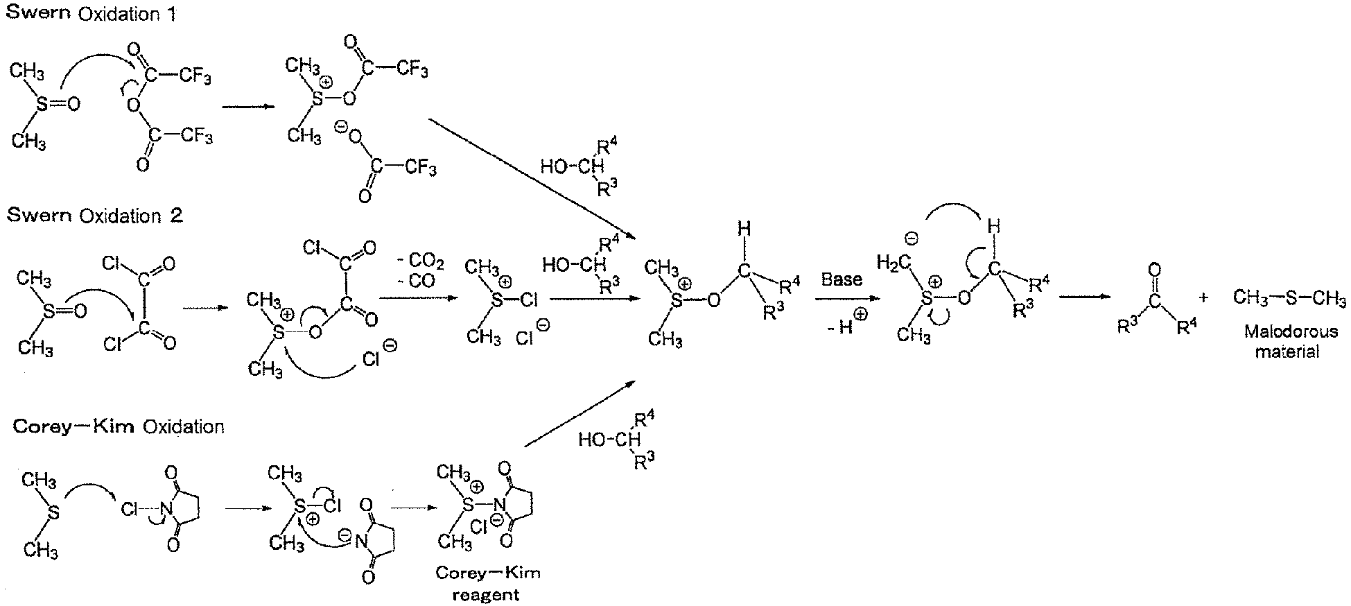
- Herein, R3 and R4 are R3 and R4 in Formulas (A) and (B) described below.
- The organic compound produced according to the present invention is an aldehyde or ketone compound.
- In the present invention, the reaction is an oxidation reaction, more preferably an oxidation reaction using a sulfur atom-containing organic compound.
- In the present invention, the aldehyde or ketone compound is produced by a synthetic method including subjecting an alcohol compound to an oxidation reaction.
- In the present invention, the reaction step particularly preferably includes oxidizing an alcohol compound having 2 to 50 carbon atoms to form an aldehyde or ketone compound having 2 to 50 carbon atoms.
- The oxidation of the alcohol compound is preferably Swern oxidation or Corey-Kim oxidation, and particularly preferably Swern oxidation.
- Therefore, at least the sulfur atom-containing organic compound described above is used as an activator.
- In the Swern oxidation, the sulfur atom-containing organic compound is a sulfoxide compound such as dimethyl sulfoxide. In the Corey-Kim oxidation, the sulfur atom-containing organic compound is a sulfide compound such as dimethyl sulfide.
- In the Swern oxidation, a sulfoxide compound such as dimethyl sulfoxide is reduced into a sulfide compound such as dimethyl sulfide. In the Corey-Kim oxidation, some amount of a sulfide compound such as dimethyl sulfide can remain unreacted in the reaction liquid.
- In a preferred mode of the present invention, an alcohol compound having 2 to 50 carbon atoms is used as a raw material and oxidized to produce an aldehyde or ketone compound having 2 to 50 carbon atoms.
- The alcohol compound, and the aldehyde compound or the ketone compound each is preferably a compound represented by Formula (A) or (B).

- In Formulas (A) and (B), R3 represents a hydrogen atom, an alkyl group, a cycloalkyl group, an alkenyl group, a cycloalkenyl group, an aryl group, or a heterocyclic group. R4 represents an alkyl group, a cycloalkyl group, an alkenyl group, a cycloalkenyl group, an aryl group, or a heterocyclic group. Herein, R3 and R4 may combine together to form a ring.
- The alkyl group of R3 and R4 is a linear or branched alkyl group having preferably 1 to 18 carbon atoms, more preferably 1 to 12 carbon atoms.
- Examples of the alkyl group include methyl, ethyl, propyl, isopropyl, butyl, pentyl, hexyl, heptyl, octyl, 2-ethylhexyl, nonyl, decyl, undecyl, dodecyl, tridecyl, tetradecyl, pentadecyl, hexadecyl, heptadecyl, and octadecyl.
- The cycloalkyl group of R3 and R4 is preferably a 3- to 18-membered cycloalkyl group, more preferably a 3- to 10-membered cycloalkyl group, further preferably a 3- to 7-membered cycloalkyl group, and particularly preferably a 5- or 6-membered cycloalkyl group. The number of carbon atoms of the cycloalkyl group is preferably 3 to 18, more preferably 5 to 12.
- Examples of the cycloalkyl group include cyclopropyl, cyclobutyl, cyclopentyl, cyclohexyl, cycloheptyl, cyclooctyl, cyclononyl, cyclodecyl, cycloundecyl, cyclododecyl, cyclotridecyl, cyclotetradecyl, cyclopentadecyl, cyclohexadecyl, cycloheptadecyl, and cyclooctadecyl.
- The alkenyl group of R3 and R4 is a linear or branched alkenyl group having preferably 2 to 18 carbon atoms, more preferably 2 to 12 carbon atoms.
- Examples of the alkenyl group include vinyl, allyl, propenyl, butenyl, pentenyl, hexenyl, heptenyl, octenyl, nonenyl, decenyl, undecenyl, dodecenyl, tridecenyl, tetradecenyl, pentadecenyl, hexadecenyl, heptadecenyl, octadecenyl, hexadienyl, dodecadienyl, octatrienyl, and tetradecatrienyl.
- The cycloalkenyl group of R3 and R4 is preferably a 5- to 18-membered cycloalkenyl group, more preferably a 5- to 10-membered cycloalkenyl group, further preferably a 5- to 7-membered cycloalkenyl group, and particularly preferably a 5- or 6-membered cycloalkenyl group. The number of carbon atoms of the cycloalkenyl group is preferably 5 to 18, more preferably 5 to 12.
- Examples of the cycloalkenyl group include cyclopentenyl, cyclohexenyl, cycloheptynyl, and cyclooctynyl.
- The number of carbon atoms of the aryl group of R3 and R4 is preferably 6 to 14, more preferably 6 to 10. Examples thereof include a monocyclic or bicyclic aryl group, such as phenyl, tolyl, xylyl, naphthyl and phenanthryl.
- The heterocyclic group of R3 and R4 is preferably a 5- to 18-membered heterocyclic group, more preferably a 5- to 10-membered heterocyclic group. The hetero atom constituting the heterocycle is preferably an atom selected from a nitrogen atom, an oxygen atom and a sulfur atom. The number of hetero atoms constituting the heterocycle may be 2 or more. The heterocycle of the heterocyclic group may be condensed with an aryl ring, such as a benzene ring, and a naphthalene ring; an aliphatic hydrocarbon ring, such as a cyclopentane ring, a cyclohexane ring, a cyclopentene ring, and a cyclohexene ring; a heterocycle, or the like.
- Examples of the heterocyclic group include imidazolyl, oxazolyl, triazolyl, thiazolyl, 1,3,4-thiadiazolyl, pyridyl, pyrimidyl, pyrazyl, furyl, pyranyl, chromanyl, tetrahydropyranyl, thienyl, benzothiazolyl, benzoxazolyl, quinolyl, and acridinyl. Other examples thereof include 5- to 16-membered lactone rings, such as 2-oxo-oxetanyl, 2-oxo-oxolanyl, 2-oxo-chromenyl, 2-oxo-isochromenyl, 2-oxo-oxepanyl, 2-oxo-oxacyclodecanyl, 2-oxo-oxacycloundecanyl, 2-oxo-oxacyclododecanyl, 2-oxo-oxacyclotridecanyl, 2-oxo-oxacyclotetradecanyl, 2-oxo-oxacyclopentadecanyl, and 2-oxo-oxacyclohexadecanyl.
- Examples of the ring formed by combining of R3 and R4 in combination include a saturated or unsaturated aliphatic carbon ring, and a saturated or unsaturated heterocycle. The formed ring is preferably a 3- to 18-membered ring. In the case of the heterocycle, the hetero atom constituting the heterocycle is preferably an atom selected from a nitrogen atom, an oxygen atom and a sulfur atom, and the number of hetero atoms constituting the heterocycle may be 2 or more.
- Among these, the heterocycle is preferably a 5- to 18-membered ring. In the case of the lactone ring, a 4- to 18-membered ring is preferable.
- Examples of the ring formed by combining of R3 and R4 in combination include the following rings.
- Examples thereof include a cyclopropane ring, a cyclobutane ring, a cyclopentane ring, a cyclohexane ring, a cycloheptane ring, a cyclooctane ring, a cyclononane ring, a cyclodecane ring, a cycloundecane ring, a cyclododecane ring, a cyclotridecane ring, a cyclotetradecane ring, a cyclopentadecane ring, a cyclohexadecane ring, a cycloheptadecane ring, and a cyclooctadecane ring.
- Examples thereof include a 1,2,3,4-tetrahydronaphthalene ring, a 9,10-dihydroanthracene ring, and a tetrahydroanthracene ring.
- Examples thereof include a cyclopropene ring, a cyclobutene ring, a cyclopentene ring, a cyclohexene ring, a cycloheptene ring, a cyclooctadiene ring, a cyclononene ring, a cyclodecene ring, a cycloundecene ring, a cyclododecatriene ring, a cyclotridecene ring, a cyclotetradecadiene ring, a cyclopentadecene ring, a cyclohexadecene ring, a cycloheptadecene ring, and a cyclooctadecene ring.
- Examples thereof include an oxolane ring; a thiopyran ring; a crown ether ring, such as a 12-crown-4-ether ring, and a 15-crown-5-ether ring; and a lactone ring, such as a β-propiotactone ring, a γ-butyrolactone ring, and a δ-valerolactone ring.
- R3, R4 and the ring formed by combining of R3 and R4 in combination may have a substituent. Such a substituent may be of any type as long as it will neither inhibit the oxidation reaction nor cause any side reaction. For example, examples of the substituent include the followings:
- an alkyl group (preferably an alkyl group having 1 to 10 carbon atoms, e.g. methyl, ethyl, isopropyl, t-butyl, pentyl, heptyl, 1-ethylpentyl, 2-ethylhexyl, benzyl, 2-ethoxyethyl, or 1-carboxymethyl), an alkenyl group (preferably an alkenyl group having 2 to 20 carbon atoms, e.g. vinyl, allyl, or oleyl), an alkynyl group (preferably an alkynyl group having 2 to 20 carbon atoms, e.g. ethynyl, 2-butynyl, or phenylethynyl), a cycloalkyl group (preferably a cycloalkyl group having 3 to 20 carbon atoms, e.g. cyclopropyl, cyclopentyl, cyclohexyl, or 4-methylcyclohexyl), an aryl group (preferably an aryl group having 6 to 26 carbon atoms, e.g. phenyl, 1-naphthyl, 2-naphthyl, 4-methoxyphenyl, 2-chlorophenyl, or 3-methylphenyl), a heterocyclic group (preferably a heterocyclic group having 0 to 20 carbon atoms, of which the hetero atom constituting the ring is preferably selected from an oxygen atom, a nitrogen atom, and a sulfur atom; the group may be a 5- or 6-membered ring and condensed with a benzene ring or a heterocycle; and the heterocycle of the heterocyclic group may be a saturated ring, an unsaturated ring or an aromatic ring, e.g. 2-pyridyl, 4-pyridyl, 2-imidazolyl, 2-benzimidazolyl, 2-thiazolyl, or 2-oxazolyl), an alkoxy group (preferably an alkoxy group having 1 to 20 carbon atoms, e.g. methoxy, ethoxy, isopropyloxy, or benzyloxy), an aryloxy group (preferably an aryloxy group having 6 to 26 carbon atoms, e.g. phenoxy,1-naphthyloxy, 2-naphthyloxy, 3-methylphenoxy, or 4-methoxyphenoxy), a heterocyclic oxy group (preferably a heterocyclic oxy group of the heterocyclic group described above),
- an alkylthio group (preferably an alkylthio group having 1 to 20 carbon atoms, e.g. methylthio, ethylthio, isopropylthio, or benzylthio), an arylthio group (preferably an arylthio group having 6 to 26 carbon atoms, e.g. phenylthio, 1-naphthylthio, 2-naphthylthio, 3-methylphenylthio, or 4-methoxyphenylthio), an acyl group (preferably an acyl group having 20 or less carbon atoms including an alkylcarbonyl group, an alkenylcarbonyl group, an arylcarbonyl group and a heterocyclic carbonyl group, e.g. acetyl, pivaloyl, acryloyl, methacryloyl, benzoyl or nicotinoyl), an alkoxycarbonyl group (preferably an alkoxycarbonyl group having 2 to 20 carbon atoms, e.g. ethoxycarbonyl, or 2-ethylhexyloxycarbonyl), an aryloxycarbonyl group (preferably an aryloxycarbonyl group having 7 to 20 carbon atoms, e.g. phenyloxycarbonyl, or naphthyloxycarbonyl), an amino group (preferably an amino group having 0 to 20 carbon atoms including an amino group, an alkylamino group, an arylamino group, and a heterocyclic amino group, e.g. amino, N,N-dimethylamino, N,N-diethylamino, N-ethylamino, anilino, 1-pyrrolidine-1-yl, piperidine-1-yl, morpholine-1-yl, or thiomorpholine-1-yl), a sulfonamide group (preferably a sulfonamide group having 0 to 20 carbon atoms including an alkylsulfonamide group and an arylsulfonamide group, e.g. sulfonamide, N,N-dimethylsulfonamide, or N-phenylsulfonamide), a sulfamoyl group (preferably a sulfamoyl group having 0 to 20 carbon atoms including an alkylsulfamoyl group and an arylsulfamoyl group, e.g. sulfamoyl, N,N-dimethylsulfamoyl, or N-phenylsulfamoyl), an acyloxy group (preferably an acyloxy group having 1 to 20 carbon atoms, e.g. acetyloxy, or benzoyloxy), a carbamoyl group (preferably a carbamoyl group having 1 to 20 carbon atoms including an alkylcarbamoyl group and an arylcarbamoyl group, e.g. carbamoyl, N,N-dimethylcarbamoyl, or N-phenylcarbamoyl), an acylamino group (preferably an acylamino group having 1 to 20 carbon atoms, e.g. acetylamino, acryloylamino, benzoylamino, or nicotinamide), a cyano group, a nitro group, a hydroxy group, a mercapto group, a carboxy group, a sulfo group, a phosphate group, a halogen atom (e.g. fluorine atom, chlorine atom, bromine atom, or iodine atom), and an azido group (-N3). Another examples thereof include an oxo group (=O) of a divalent group.
- These substituents may be further substituted with the substituent described above.
- Among these, an alkyl group, a cycloalkyl group, an alkenyl group, a cycloalkenyl group, an alkynyl group, an aryl group, a heterocyclic group, an alkoxy group, an aryloxy group, a heterocyclic oxy group, an amino group, an acyl group, an alkoxycarbonyl group, a halogen atom, an oxo group, and a group formed by the combination of these are preferable.
- R3 is preferably a hydrogen atom, an alkyl group having 1 to 12 carbon atoms, an alkenyl group having 2 to 12 carbon atoms, a phenyl group, a naphthyl group, or a 5- to 18-membered heterocyclic group.
- R4 is preferably an alkyl group having 1 to 12 carbon atoms, an alkenyl group having 2 to 12 carbon atoms, a phenyl group, a naphthyl group, or a 5- to 18-membered heterocyclic group.
- Further, the ring formed by combining of R3 and R4 in combination is also preferable; and a 6- to 14-membered saturated ring, a 5- to 14-membered heterocycle and a 14- to 16-membered lactone ring are more preferable.
- In this regard, the compounds represented by Formulas (A) and (B) may have one or more asymmetric carbon atoms depending on the substituent type, and any optical isomers, diastereoisomers, and mixtures thereof based on such asymmetric carbon atoms will also fall within the scope of the present invention.
- In addition, when these compounds have one or more double bonds in the R3 or R4 group, any geometrical isomers based on such double bonds will also fall within the scope of the present invention.
- Specific examples of the compound represented by Formula (A) are described below. However, the present invention is not limited to these examples.
- The compound represented by Formula (B) may be one derived from the compound represented by Formula (A) by replacing >CH-OH by >C(=O). Therefore, examples of the compound represented by Formula (B) may be those derived from the above examples of the compound represented by Formula (A) by replacing >CH-OH by >C(=O).


- In the above, "Bz" represents a benzoyl group, "Bzl" represents a benzyl group, and "Cbz" represents a benzyloxycarbonyl group.
- The compound represented by Formula (A) (alcohol compound) can be synthesized by a known method, e.g., a method described in Journal of Antibiotics, 2011, 64, 333-337; Journal of Antibiotics, 1996, 49, 493-495; Tetrahedron Letters, 2005, 46, 1483-1487; European Journal of Medicinal Chemistry, 2013, 69, 174-181; or the like.
- In the present invention, a mixture of the compound represented by Formula (A) and an activator is particularly preferably subjected to the reaction.
- Such an activator is preferably a combination of an acid anhydride or an acid halide (acid halide compound) and a sulfoxide compound, or a combination of an N-halo cyclic imide compound (N-halogenated cyclic imide compound) and a sulfide compound.
- In the present invention, the combination of an acid anhydride or acid halide, and a sulfoxide compound is particularly preferable.
- The sulfoxide compound is preferably a sulfoxide compound represented by Formula (SO).

- In Formula (SO), R1 and R2 have the same meaning as R1 and R2 in the sulfide compound represented by Formula (S), and preferable ranges are also the same.
- Also in the case of the sulfoxide compound, it is preferable that R1 and R2 each are an alkyl group. Among these, it is more preferable that the total number of carbon atoms of R1 and R2 is from 2 to 8.
- Examples of the dialkyl sulfoxide compound having 2 to 8 carbon atoms include dimethyl sulfoxide, diethyl sulfoxide, dipropyl sulfoxide, diisopropyl sulfoxide, dibutyl sulfoxide, ethylmethyl sulfoxide, propylmethyl sulfoxide, isopropylmethyl sulfoxide, butylmethyl sulfoxide, butylethyl sulfoxide, butylpropyl sulfoxide, and butylisopropyl sulfoxide. Among these, dimethyl sulfoxide, diethyl sulfoxide, dipropyl sulfoxide and dibutyl sulfoxide are preferable; and dimethyl sulfoxide is more preferable.
- Various sulfoxide compounds are commercially available and can be obtained. Alternatively, the sulfoxide compound can be synthesized in accordance with a known method (e.g., a method described in Tetrahedron Lett., vol. 43, p. 5177-5179 (2002), or the like).
- The acid anhydride for use in combination with the sulfoxide compound may be any of an aliphatic carboxylic acid anhydride, an aromatic carboxylic acid anhydride, a heterocyclic carboxylic acid anhydride, and any mixture of these carboxylic acid anhydrides. The acid hydride may have a chain or cyclic structure.
- In the present invention, an aliphatic carboxylic acid anhydride is preferred, and a chain acid anhydride is more preferred.
- The acid anhydride of the aliphatic carboxylic acid preferably has 4 to 10 carbon atoms, and may have a substituent. Such a substituent may be a substituent with which each of the R3 and R4 groups in Formulas (A) and (B) can be substituted. Preferably, such a substituent is a halogen atom.
- Examples of the acid anhydride include acetic anhydride, butyric anhydride, isobutyric anhydride, pivalic anhydride, trifluoroacetic anhydride, heptafluoroacetic anhydride, and trichloroacetic anhydride. Among these, acetic anhydride, trifluoroacetic anhydride, and trichloroacetic anhydride are preferable; and trifluoroacetic anhydride and trichloroacetic anhydride are more preferable.
- The acid halide for use in combination with the sulfoxide compound may be a carboxylic acid halide, a sulfonic acid halide, a cyanuric acid halide, a thionyl halide, a phosphorus trihalide, or a phosphorus oxyhalide.
- The carboxylic or sulfonic acid may be any of an aliphatic, aromatic, or heterocyclic carboxylic or sulfonic acid.
- The acid halide may also have two or more -C(=O)X or -SO2X moieties, in other words, may also be a di- or poly-valent acid halide. Herein, X represents a halogen atom.
- The aliphatic carboxylic acid for the aliphatic carboxylic acid halide is preferably an alkane carboxylic acid, which preferably has 1 to 10 carbon atoms, more preferably has 2 to 7 carbon atoms. The aromatic carboxylic acid for the aromatic carboxylic acid halide preferably has 6 to 10 carbon atoms, more preferably 6 or 7 carbon atoms. Such an aromatic carboxylic acid may be benzenecarboxylic acid or naphthalenecarboxylic acid. The heterocycle of the heterocyclic carboxylic acid halide is preferably one represented by R3 or R4 in Formula (A) or (B). The number of carbon atoms of the acid halide of a heterocyclic carboxylic acid is preferably 2 to 7.
- The aliphatic sulfonic acid for the aliphatic sulfonic acid halide is preferably an alkane sulfonic acid, which preferably has 1 to 10 carbon atoms, more preferably has 2 to 7 carbon atoms. The aromatic sulfonic acid for the aromatic sulfonic acid halide preferably has 6 to 10 carbon atoms, more preferably 6 or 7 carbon atoms. Such an aromatic sulfonic acid may be benzenesulfonic acid or naphthalenesulfonic acid. The heterocycle of the heterocyclic sulfonic acid halide is preferably one represented by R3 or R4 in Formula (A) or (B). The number of carbon atoms of the acid halide of a heterocyclic sulfonic acid is preferably 2 to 7.
- In the present invention, the acid halide is preferably an acid halide of a monovalent or divalent aliphatic carboxylic acid, an acid halide of an aromatic carboxylic acid, an acid halide of an aromatic carboxylic acid, an acid halide of an aliphatic sulfonic acid, a halide of cyanuric acid, a thionyl halide, a phosphorus trihalide, and a phosphorus oxyhalide.
- Further, the number of carbon atoms of the acid halide is preferably 2 to 7, as described above.
- The acid halide is preferably an acid chloride or an acid bromide, and particularly preferably an acid chloride.
- Preferred examples of the acid chloride include oxalyl chloride, cyanuric chloride, benzoyl chloride, methanesulfonyl chloride, thionyl chloride, phosphorus trichloride, phosphorus oxychloride, and acetyl chloride. Among these, oxalyl chloride is particularly preferable.
- The amount of the sulfoxide compound to be used is preferably 1.0 to 5.0 molar equivalents, more preferably 1.5 to 4.5 molar equivalents, further more preferably 2.0 to 4.0 molar equivalents, based on the amount of the raw material alcohol compound.
- The amount of the acid anhydride or acid halide to be used is preferably 1.0 to 3.0 molar equivalents, more preferably 1.1 to 2.8 molar equivalents, further more preferably 1.2 to 2.5 molar equivalents, based on the amount of the raw material alcohol compound.
- In the present invention, the sulfoxide compound may be mixed in advance with the acid anhydride or the acid halide, and the resulting mixture may be mixed with the raw material alcohol compound. Alternatively, the sulfoxide compound, the acid anhydride or the acid halide, and the raw material alcohol compound may be mixed simultaneously.
- The sulfide compound represented by Formula (S) described above is preferably used in the Corey-Kim oxidation.
- The N-halo cyclic imide compound for use in combination with the sulfide compound preferably has a 5- or 6-membered imide ring, more preferably a 5-membered imide ring. Examples of the imide ring include succinimide, hexahydrophthalimide, 2,2-dimethylsuccinimide, 2-ethyl-2-methylsuccinimide, methyleneglutarimide, 3,3-dimethylglutarimide, 3-ethyl-3-methylglutarimide, and 3,3-tetramethyleneglutarimide. Among these, succinimide is particularly preferable. The halogen atom at the N-position is preferably a chlorine atom or a bromine atom, more preferably a chlorine atom. As the N-halo cyclic imide compound, N-chlorosuccinimide is particularly preferable.
- The amount of the sulfide compound to be used is preferably 1.0 to 5.0 molar equivalents, more preferably 1.2 to 4.0 molar equivalents, further more preferably 1.5 to 3.0 molar equivalents, based on the amount of the raw material alcohol compound.
- The amount of the N-halo cyclic imide compound to be used is preferably 1.0 to 4.0 molar equivalents, more preferably 1.2 to 3.3 molar equivalents, further more preferably 1.5 to 2.5 molar equivalents, based on the amount of the raw material alcohol compound.
- The sulfide compound may be mixed in advance with the N-halo cyclic imide compound, and the resulting mixture may be mixed with the raw material alcohol compound. Alternatively, the sulfide compound, the N-halo imide compound, and the raw material alcohol compound may be mixed simultaneously. In a preferred mode of the present invention, the sulfide compound is mixed in advance with the N-halo cyclic imide compound, and the resulting mixture is mixed with the raw material alcohol compound.
- A base is used in the reaction between the raw material alcohol compound and the activator. The base is preferably pyridine or a tertiary amine compound, more preferably a tertiary amine compound.
- The tertiary amine compound may be an aliphatic, aromatic, or heterocyclic tertiary amine compound. A cyclic tertiary amine compound may also be used.
- The nitrogen atom may be substituted with an aliphatic group substituent. In this case, the aliphatic group is preferably an alkyl group or a cycloalkyl group. In the case of the alkyl group, the alkyl group preferably has 1 to 18 carbon atoms. In the case of the cycloalkyl group, preferred thereof include cyclopentyl and cyclohexyl, and the cycloalkyl group preferably has 5 to 18 carbon atoms.
- The nitrogen atom may be substituted with an aromatic group substituent. In this case, the aromatic group preferably has 6 to 18 carbon atoms, and examples of the aromatic group include a phenyl group and a naphthyl group.
- The nitrogen atom may also be substituted with a heterocyclic group substituent. In this case, the heterocyclic group is preferably one exemplified as R3 or R4 in Formula (A) or (B).
- Two or three substituents on the nitrogen atom may be combined together to form a ring. Such a ring is preferably a 5- or 6-membered ring. Such a ring may be fused with any other ring. Such a ring may also be a crosslinked ring. Examples thereof include a pyrrolidine ring, a piperazine ring, a morpholine ring, a thiomorpholine ring, a quinuclidine ring, and a 1,4-diazabicyclo[2.2.2]octane ring (DABCO).
- Various tertiary amine compounds are commercially available and can be easily obtained.
- Examples of the tertiary amine compound include trimethyl amine, dimethyl ethyl amine, diethyl methyl amine, triethyl amine, diethyl methyl amine, dimethyl isopropyl amine, dipropyl ethyl amine, diisopropyl ethyl amine, butyl dimethyl amine, butyl diisopropyl amine, tributyl amine, triisobutyl amine, triamyl amine, triisoamyl amine, cyclohexyl dimethyl amine, dicyclohexyl methyl amine, cyclohexyl diethyl amine, dicyclohexyl ethyl amine, butyl dicyclohexyl amine, triheptyl amine, dimethyl octyl amine, methyl dioctyl amine, trioctyl amine, tris(2-ethylhexyl) amine, trinonyl amine, dimethyl decyl amine, tridecyl amine, triundecyl amine, dimethyl dodecyl amine, didodecyl methyl amine, tridodecyl amine, dimethyltetradecyl amine, dimethyl hexadecyl amine, dimethyl octadecyl amine, dioctadecyl methyl amine, N-methylmorpholine, N-ethylmorpholine, quinuclidine, and 1,4-diazabicyclo[2.2.2]octane.
- Among these, triethyl amine, diisopropyl ethyl amine, dicyclohexyl methyl amine, and cyclohexyl diethyl amine are preferable.
- The amount of the base to be used is preferably 1.2 to 6.0 molar equivalents, more preferably 1.3 to 5.5 molar equivalents, further more preferably 1.5 to 5.0 molar equivalents, based on the amount of the raw material alcohol compound.
- After the raw material alcohol compound and the activator are mixed, the base may be mixed with the resulting mixture. Alternatively, the base, the raw material alcohol compound, and the activator may be mixed at the same time. It is preferable that the raw material alcohol compound and the activator are mixed, and then the base is mixed with the resulting mixture.
- The reaction solvent may be any type capable of dissolving the substrate and not undergoing any side reaction.
- A single solvent or a mixture of two or more solvents may be used.
- Examples of the reaction solvent include a ketone-series solvent, such as acetone, ethyl methyl ketone, methyl isopropyl ketone, diisopropyl ketone, methyl isobutyl ketone, and diisobutyl ketone; an ether-series solvent, such as diethyl ether, diisopropyl ether, methyl-tert-butyl ether, tetrahydrofuran (THF), and dioxane; an amide-series solvent, such as dimethylformamide, dimethylacetamide, N-methyl-2-pyrolidone, tetramethylurea, and 1,3-dimethyl imidazolinone; a sulfur-containing solvent, such as dimethyl sulfoxide and sulfolane; a nitrile-series solvent, such as acetonitrile; a glycol-series solvent, such as ethylene glycol dimethyl ether, propylene glycol diethyl ether, diethylene glycol dimethyl ether, diethylene glycol ethyl methyl ether, ethylene glycol diacetate, ethylene glycol distearate, ethylene glycol diacrylate, and diethylene glycol diacetate; a halogen-series solvent, such as methylene chloride, chloroform, and chlorobenzene; an ester-series solvent, such as methyl acetate, ethyl acetate, isopropyl acetate, and butyl acetate; an aromatic hydrocarbon-series solvent, such as toluene, xylene, mesitylene, and tetrahydronaphthalene; and a terpene-series solvent, such as terpinene, terpinolene, cymene, and phellandrene.
- Among these, acetone, THF, acetonitrile, methylene chloride, ethyl acetate, and toluene are preferable.
- The amount of the solvent to be used is generally 1 to 300 mL, preferably 1 to 150 mL, more preferably 5 to 100 mL, based on 1 g of the raw material alcohol compound, through it depends on the substrate and the reaction conditions.
- The reaction step may be performed in a batch method under normal conditions (e.g., see Jikken Kagaku Koza (Handbook of Experimental Chemistry), 4th ed., volume 23, 1991, published by Maruzen Company Ltd.).
- When the reaction is performed as a flow reaction, the reaction temperature is preferably -30 to 60°C, more preferably -25 to 50°C, further more preferably -20 to 40°C. In the flow reaction, the mixing temperature is preferably -30 to 40°C, more preferably -20 to 30°C. In the flow reaction, the reaction time is preferably 0.001 to 60 seconds, more preferably 0.005 to 50 seconds, further more preferably 0.01 to 40 seconds, particularly more preferably 0.02 to 30 seconds.
- The raw material alcohol compound, the activator, the individual components of the activator, and the base may be each dissolved in the solvent and then mixed together, or may be mixed as they are without being dissolved in the solvent.
- In the reaction step, the reaction may be performed in a batch method or as a flow reaction in a flow passage.
- In the present invention, the reaction is preferably performed as a flow reaction in the same flow passage as that for the deodorization step, and, in particular, preferably performed in a microreactor.
- The method of removing the odor of the malodorous material may be a method including converting the malodorous material into a quaternary salt as a water-soluble compound using methyl halide or other materials and removing the water-soluble compound; or a method of removing the odor of the malodorous material by oxidation reaction using an oxidizing agent. Preferred method is a method of removing the odor of the malodorous material by oxidation reaction.
- The oxidizing agent may be arbitrarily selected. A wide variety of oxidizing agents is commercially available and can be easily obtained. Examples of the oxidizing agent include oxo acids of halogen (or salts thereof), including hypochlorous acid or salts thereof, organic peroxides, inorganic peroxides, halogenating agents, hypervalent iodine compounds, N-oxide compounds, and nitroxyl radical (>N•) compounds.
- In the present invention, the oxidizing agent is preferably liquid or soluble in the solvent because the deodorization step is performed using a flow reaction in a flow passage.
- However, if the oxidizing agent is solid and insoluble in the solvent, the oxidizing agent may be charged in the flow passage, and the liquid may be passed through the flow passage to undergo oxidation reaction.
- In the present invention, the odor of the malodorous material is removed using a flow reaction in a flow passage, which makes it possible to efficiently and selectively remove the malodorous material in a short time, in other words, makes it possible to convert the malodorous material into a non-malodorous material. Therefore, the malodorous material can be selectively converted into a non-malodorous material even if the organic compound obtained in the reaction step has an unstable or reactive functional group, such as a double bond, an ester bond (-OC(=O)-), an amino group, an azido group (-N3), a hydroxy group, an acyloxy group, a benzyloxy group, a nitro group, a formyl group, or an acyl group.
- A reaction scheme is shown below, in which hypochlorous acid (HOCI) is used to convert a sulfide compound, a malodorous material, into a sulfone compound. Herein, R1 and R2 have the same meaning as those in Formula (S).

- The oxo acid (or a salt thereof) of the halogen is preferably oxo acid (or a salt thereof) of chlorine, and specific examples thereof include perchloric acid, hypochlorous acid, chlorous acid and chloric acid (or a salt of these). Among these, hypochlorous acid, chlorous acid or chloric acid (or a salt of these) is preferable; and a hypochlorous acid salt aqueous solution is particularly preferable.
- Specific examples of the organic peroxide include benzoyl peroxide, tert-butyl hydroperoxide, bis(trimethylsilyl) peroxide, 3-chloroperoxybenzoic acid, cumene hydroperoxide, di-tert-butyl peroxide, peracetic acid/acetic acid solution, and peracetic acid/hydrogen peroxide solution. Among these, peracetic acid/acetic acid solution and peracetic acid/hydrogen peroxide solution are preferable, and peracetic acid/hydrogen peroxide solution is particularly preferable.
- A specific example of the inorganic peroxide includes hydrogen peroxide solution.
- Examples of the hypervalent iodine compound include 1-acetoxy-5-bromo-1,2-benziodoxol-3(1H)-one, [bis(trifluoroacetoxy)iodo]benzene, [bis(trifluoroacetoxy)iodo]pentafluorobenzene, 1-(tert-butylperoxy)-1,2-benziodoxol-3(1H)-one, bis(pyridine)iodonium tetrafluoroborate, Dess-Martin periodinane, iodosobenzene, 2-iodosobenzoic acid, iodobenzene diacetate, 2-iodoxybenzoic acid, and [hydroxy(tosyloxy)iodo]benzene.
- Examples of the halogenating agent include N-chlorosuccinimide, N-bromosuccinimide, N-chlorophthalimide, N-bromophthalimide, 1,3-dichloro-5,5-dimethylhydantoin, 1,3-dibromo-5,5-dimethylhydantoin, trichloroisocyanuric acid, tribromoisocyanuric acid, N-iodosuccinimide, and 1,3-diiodo-5,5-dimethylhydantoin. Among these, N-chlorosuccinimide, N-bromosuccinimide, 1,3-dichloro-5,5-dimethylhydantoin, and 1,3-dibromo-5,5-dimethylhydantoin are preferable; and N-chlorosuccinimide and 1,3-dichloro-5,5-dimethylhydantoin, which are low-priced, are more preferable.
- Examples of the N-oxide compound include 2,6-dichloropyridine-N-oxide, 4-(dimethylamino)pyridine-N-oxide hydrate, 2,6-lutidine-N-oxide, 4-methylmorpholine-N-oxide, pyridine-N-oxide, trimethylamine-N-oxide dihydrate, and trimethylamine-N-oxide anhydride.
- The nitroxyl radical compound is preferably a 5- or 6-membered compound, more preferably a compound in which both substituent carbon atoms on the nitrogen atom of >N-O• form two alkyl groups (preferably methyl groups), further more preferably a compound having a 2,2,6,6-tetramethylpiperidin-1-oxyl (TEMPO) skeleton.
- Examples of the compound having a TEMPO skeleton include 4-acetylamino-TEMPO, 4-benzoyloxy-TEMPO, 4-[2-[2-(4-iodophenoxy)ethoxy] carbonyl]benzoyloxy-2,2,6,6-tetramethylpiperidin-1-oxyl, 4-methoxy-TEMPO, and TEMPO.
- In the present invention, the oxidizing agent is preferably selected from hypochlorous acid or a salt thereof, a halogenating agent, and peracetic acid.
- These oxidizing agents are liquid and suitable for the flow reaction in the flow passage. Using any of these oxidizing agents, the malodorous material can be very selectively converted into a non-malodorous material even if the organic compound obtained in the reaction step has an unstable or reactive functional group.
- The amount of the oxidizing agent to be used is preferably 0.5 to 5.0 molar equivalents, more preferably 1.0 to 5.0 molar equivalents, further more preferably 1.1 to 4.5 molar equivalents, particularly preferably 1.2 to 4.0 molar equivalents, based on the amount of the acid anhydride or the acid halide to be used in the reaction step.
- The solvent for use in the deodorization step may be the same or different from the solvent for use in the reaction step described above.
- The amount of the solvent to be used may be the same as that in the reaction step described above, though it depends on the substrate and reaction conditions.
- The solvent may be further added to the reaction liquid obtained in the reaction step. In the present invention, however, the reaction liquid obtained in the reaction step is preferably subjected as it is to the flow reaction in the flow passage. The solvent further added to the reaction liquid obtained in the reaction step may be the same as or different from the solvent in the reaction step.
- The oxidizing agent may be dissolved in the solvent and then mixed with the reaction liquid obtained in the reaction step. Alternatively, only the oxidizing agent may be mixed with the reaction liquid obtained in the reaction step.
- In the present invention, the reaction temperature in the deodorization step is preferably from -20 to 60°C, more preferably from -10 to 55°C, further more preferably from -5 to 50°C, and particularly preferably from 0 to 40°C.
- In the present invention, the time for which the deodorization step is retained in the flow passage (reaction time) is preferably 0.01 to 120 seconds, more preferably 0.01 to 60 seconds, further more preferably 0.05 to 50 seconds, particularly preferably 0.1 to 40 seconds, most preferably 0.2 to 30 seconds.
- When the flow reaction in the flow passage is performed using a microreactor, the flow passage of the micromixer (e.g.,
Fig. 1 shows flow passages betweenpoints points 4 and 5, and immediately downstream ofpoint 5, respectively) may have any inner diameter or any cross-sectional area. In the present invention, however, the inner diameter (cross-sectional area) of the flow passage is preferably 0.05 to 5.0 mm (0.00196 to 19.6 mm2), more preferably 0.10 to 2.5 mm (0.00785 to 4.9 mm2), further more preferably 0.15 to 1.5 mm (0.018 to 1.8 mm2). - In this regard, the cross-sectional shape of the flow passage described above may be circular or square.
- In the present invention, the reaction in the reaction step described above may be performed in a batch method or as a flow reaction in a flow passage, whereas the deodorization step is performed using a flow reaction in a flow passage.
- The flow reaction in the flow passage may be of any type. In particular, the flow reaction in the flow passage is preferably performed using a microreactor.
- The microreactor has very small flow passages capable of mixing a plurality of liquids. If necessary, the microreactor may have feed passages that communicate with the flow passages to feed liquids to the flow passages. If necessary, the microreactor may further have components other than the flow passages and the feed passages.
- The microreactor for use in the present invention is not particularly limited as long as it has very small flow passages capable of mixing a plurality of liquids. The microreactor may be appropriately selected, depending on the purpose, for example, from a micromixer (such as a substrate type micromixer or a joined pipe micromixer) and a branched tube.
- The substrate type micromixer, which is sometimes called a microchannel, is composed of a substrate and flow passages formed inside the substrate or on the surface of the substrate.
- The substrate type micromixer may be of any type as long as the effect of the present invention is not impaired. The substrate type micromixer may be appropriately selected, depending on the purpose, from, for example, the mixer described in
WO 96/30113 A - Besides the flow passages described above, the substrate type micromixer preferably has feed passages that communicate the flow passages to feed a plurality of liquids to the flow passages. In other words, the micromixer preferably has a structure in which the upstream side of the flow passage described above is branched depending on the number of feed passages.
- The number of feed passages is not particularly limited, and can be appropriately selected depending on the purpose. Preferably, a plurality of liquids to be mixed are fed from separate feed passages and joined and mixed together in the flow passage. Alternatively, the micromixer may be so configured that one liquid can be previously charged into a flow passage, and another liquid can be fed from a feed passage to the flow passage.
- The joined pipe micromixer has flow passages formed in the interior and optionally connection means for connecting tubes to the flow passages formed in the interior. The connection means is not particularly limited, and can be appropriately selected depending on the purpose from known tube connection types, such as a screw type, a union type, a butt weld type, a socket welding type, a socket weld type, a flange type, a bite type, a flare type, and a mechanical type.
- Besides the flow passages described above, feed passages that communicate the flow passages to feed a plurality of liquids to the flow passages are preferably formed in the interior of the joined pipe micromixer. In other words, the micromixer preferably has a structure in which the upstream side of the flow passage described above is branched depending on the number of feed passages. When two feed passages are provided, the joined pipe micromixer may be of, for example, T-shaped or Y-shaped. When three feed passages are provided, the joined pipe micromixer may be, for example, cruciform. Alternatively, the micromixer may be so configured that one liquid can be previously charged into a flow passage, and another liquid can be fed from a feed passage to the flow passage.
- The material of the micromixer is not particularly limited, and can be appropriately selected depending on requirements such as heat resistance, pressure resistance, solvent resistance, and easy workability. Examples of the material of the micromixer include metals or alloys including stainless steel, titanium, copper, nickel, aluminum, and Hastelloy (registered trademark), silicone, fluororesins such as Teflon (registered trademark) and PFA (perfluoroalkoxy resin), and TFAA (trifluoroacetamide).
- The micromixer is configured to accurately control the flow of the reactant solution by means of its microstructure. Therefore, the micromixer is preferably manufactured by micro-machining technology.
- Any micro-machining technology is not particularly limited, and can be appropriately selected depending on the purpose, for example, from (a) LIGA technology using X-ray lithography in combination with electroplating, (b) high aspect ratio photolithography using EPON-SU8, (c) mechanical micro-cutting (e.g., micro-drill processing with a high speed rotatable drill with a diameter of the order of a micrometer), (d) high aspect ratio processing of silicon using deep RIE, (e) hot embossing, (f) optical shaping, (g) laser processing, and (h) ion beam techniques.
- The micromixer may be any of commercially available micromixers such as a microreactor having an interdigital channel structure, a single mixer and a caterpillar mixer manufactured by Institut für Mikrotechnik Mainz GmbH (IMM), Micro Glass Reactor manufactured by Mikroglas GmbH, CYTOS manufactured by CPC Systems GmbH, YM-1 Mixer and YM-2 Mixer manufactured by Yamatake Co., Ltd., Mixing Tee and Tee (T-shaped connector) manufactured by SHIMADZU GLC Ltd., IMT Chip Reactor manufactured by Institute of Microchemical Technology Co., Ltd., Micro Hi-Mixer developed by Toray Engineering Co., Ltd., Union Tee manufactured by Swagelok Company, a mixer manufactured by YMC CO., LTD., and a mixer manufactured by Nakamura Choukou Co., Ltd.
- Any of these micromixers may be used alone as a microreactor, or a tube reactor may be connected to the downstream part of any of these micromixers to form an extended flow passage. The length of the flow passage can be adjusted by connecting a tube reactor to the downstream part of the micromixer.
- The time of retention of the mixed liquid (reaction time) is proportional to the length of the flow passage.
- In this regard, the tube reactor is a reactor for accurately controlling the time required for solution to undergo reaction (retention time control) after the solution is prepared by quick mixing by the micromixer.
- The tube reactor is not particularly limited. For example, the inner diameter, outer diameter, length, material, and other features of the tube may be appropriately selected depending on the desired reaction.
- The tube reactor may be any of commercially available products, such as a stainless steel tube manufactured by GL Sciences Inc. (
outer diameter 1/16 inches (1.58 mm), inner diameter selectable from 250 µm, 500 µm, 800 µm, and 1,000 µm, 1/8 inches (3.17 mm), with the tube length adjustable by the user). - The material of the tube reactor is not limited, and any of the above examples of the material of the micromixer is preferably used to form the tube reactor.
- The flow passage described above has the functions of mixing a plurality of liquids by diffusion and removing heat of reaction.
- The method of mixing the liquids in the flow passage described above is not particularly limited, and can be appropriately selected depending on the purpose, for example, from laminar mixing and turbulent mixing. In particular, laminar mixing (static mixing) is preferred because it allows more efficient reaction control or heat removal. Since the flow passage of the microreactor is very small, a plurality of liquids fed from the feed passages tends to spontaneously form dominantly laminar flows so that they are diffused and mixed in directions perpendicular to the flows. For laminar mixing, branch and meeting points may be provided in the flow passage to divide the laminar flow cross-section of the liquid, so that the mixing rate can be increased.
- Turbulent mixing (dynamic mixing) may be provided in the flow passage of the microreactor. In this case, laminar flow can be changed to turbulent flow by controlling the flow rate and the geometry of the flow passage (such as the three-dimensional shape of the liquid contact portion, the bending of the flow passage, or other shapes, or the wall surface roughness). Turbulent mixing has advantage in that it can provide higher mixing efficiency and higher mixing rate than laminar mixing.
- In this regard, the inner diameter, the cross-sectional area, length, and cross-sectional shape of the flow passage are not particularly limited and can be appropriately selected depending on the purpose.
- While the flow passage of the micromixer has been described above, the flow passage of the reactor preferably has a cross-sectional area of 0.00196 to 19.6 mm2. The cross-section may have any shape as long as it has such a cross-sectional area.
- The feed passages have the functions of communicating with the flow passage described above and feeding a plurality of liquids to the flow passage. In general, other sides of the feed passages than their sides communicating with the flow passage described above are connected to containers containing the liquids to be mixed.
- The feed passages may have any inner diameter as long as the effect of the present invention is not impaired. The inner diameter of the feed passages can be appropriately selected depending on the purpose.
- When the microreactor has a plurality of feed passages, they may have the same or different inner diameters.
- Components other than the flow passages and the feed passages described above are not particularly limited and can be appropriately selected depending on the purpose. Such components include, for example, a pump for use in liquid feeding, temperature control means, reaction acceleration means, a sensor, and a tank for storing the produced compound.
- The pump is not particularly limited, and can be appropriately selected from industrially useful pumps. Pumps free of pulsation during liquid feeding are preferred, such as plunger pumps, gear pumps, rotary pumps, and diaphragm pumps.
- The temperature control means is not particularly limited and can be appropriately selected depending on the reaction temperature. Examples of the temperature control means include a thermostatic chamber, a circulator, a heat exchanger, and a backpressure valve.
- The reaction acceleration means can be appropriately selected depending on the liquids to be mixed or the desired reaction. Examples of the reaction acceleration means include vibrational energy applying means, heating means, light irradiation means, and voltage applying means. The microreactor having voltage applying means may be, for example, the micro-flow electrochemical reactor disclosed in
JP-A-2006-104538 - The sensor is not particularly limited, and examples thereof include a temperature sensor, a flow rate sensor, and a pressure sensor for measuring the pressure in the flow passage.
- A plurality of raw materials may be supplied at the same or different flow rates to the microreactor. The pump for use in liquid feeding may be any industrially useful liquid feed pump. Preferably, the pump is of a type that can be as free as possible of pulsation during liquid feeding. The pump is preferably a plunger pump, a gear pump, a rotary pump, a diaphragm pump or the like.
- In the microreactor, liquid or solution-state compounds are mixed and reacted by the kinetic energy of the flowing liquid and solution. If necessary, however, energy for accelerating mixing, such as vibrational energy, may be applied from outside the microreactor. The mixing can be changed from static mixing (laminar flow) to dynamic mixing (turbulent flow) according to the flow rate and the geometry of the reactor (such as the three-dimensional shape of the liquid contact portion, the bending of the flow passage, or other shapes, or the wall surface roughness). The mixing may be any of turbulent mixing and laminar mixing.
- Hereinafter, a preferred reactor according to the present invention will be described with reference to
Figs. 1 and2 . -
Fig. 1 is a schematic configuration diagram showing a preferred production system for the deodorization step according to the present invention, andFig. 2 is a schematic configuration diagram showing the total configuration of a preferred production system for the process from the reaction step to the deodorization step according to the present invention. - In this case, the reaction step shown in
Fig. 2 is based on Swern oxidation or Corey-Kim oxidation. It will be understood that the reaction is not limited to Swern oxidation or Corey-Kim oxidation and solutions A and B are also not limited to solutions containing such compounds. These drawings merely show the schematic configuration of typical examples. - Hereinafter,
Figs. 1 and2 will be briefly described. - In
Fig. 1 , solution A is a solution containing a malodorous material, and solution B is a solution containing an oxidizing agent. Moreover, points 1 and 2 each are a port for supplying a raw material to the microreactor.Points 3 and 4 each are a port for supplying a raw material to the micromixer.Point 5 is a start point of mixing of the solutions A andB. Point 6 is the exit of the microreactor. In this case,section 1 to 3 (a section betweenpoints 1 and 3) is a section for controlling the temperature of solution A,section 2 to 4 (a section betweenpoints 2 and 4) is a section for controlling the temperature of solution B, andsection 5 to 6 (a section betweenpoints 5 and 6) is a section for the reaction between solutions A and B. - In
Fig. 2 , solution A1 is a solution containing an alcohol compound, and a sulfoxide compound or a sulfide compound, and solution A2 is a solution containing an acid anhydride or an N-halo cyclic imide compound. Solution A3 is a solution containing a base, and solution B is a solution containing an oxidizing agent, which is the same as solution B inFig. 1 . It will be understood that the solutions for use in the present invention are not limited to solutions A1 to A3 and B and that the compounds to be added to the respective solutions are not limited to those shown in the drawings. -
Points 7 to 10 are each a port for supplying a raw material to the microreactor.Points Point 12 is a mixing start point in a first step (a reaction between solutions A1 and A2).Point 15 is a mixing start point in a second step (a reaction with solution A3).Point 18 is a mixing start point in a third step (a reaction with solution B).Point 20 is the exit of the microreactor. The solution corresponding to solution A inFig. 1 is supplied frompoint 17. - In this case,
section 7 to 11 (a section betweenpoints 7 and 11) is a section for controlling the temperature of solution A1.Section 8 to 13 (a section betweenpoints 8 and 13) is a section for controlling the temperature of solution A2. Section 9 to 16 (a section between points 9 and 16) is a section for controlling the temperature of solution A3.Section 10 to 19 (a section betweenpoints 10 and 19) is a section for controlling the temperature of solution B. Moreover,section 12 to 14 (a section betweenpoints 12 and 14) is a section for the reaction in the first step.Section 15 to 17 (a section betweenpoints 15 and 17) is a section for the reaction in the second step.Section 18 to 20 (a section betweenpoints 18 and 20) is a section for the reaction in the third step. - The aldehyde or ketone compound obtained by the production method of the present invention can be isolated by a known method. For example, the aldehyde or ketone compound is isolated and purified using, as needed, one or any appropriate combination of extraction with an organic solvent, distillation, reprecipitation with an organic solvent, water, or a mixture of an organic solvent and water, crystallization, and column chromatography.
- The present invention will be described in more detail based on examples given below.
- The structure of the synthesized product was identified by NMR, IR, and milli-mass spectroscopy.
- The reaction rate to the desired product was determined by analyzing the content from the peak area ratio using high performance liquid chromatography (HPLC).
- The HPLC measurement was performed under the following conditions: column, Waters XBridge C18; eluent, acetonitrile/water (V/V = 7/3); buffer, 0.1% phosphoric acid; detector, UV 210 to 254 nm Corona CAD or RI; flow rate, 1.0 mL/min; column temperature, 30 to 40°C.
- The isolation yield of the product for which no standard material was commercially available was determined by silica gel column chromatography.
- Malodorous materials were quantified using No. 77 series Detector Tube manufactured by GASTEC CORPORATION or NMR analysis.
- The deodorization step was performed using the reactor shown in
Fig. 1 . - The 3'-dimethylaminoacetophenone solution (solution A) containing the malodorous material was prepared referring to the method described in J. Org. Chem., vol. 41, p. 957-962 (1976). In a methylene chloride solvent at -78°C, Swern oxidation reaction was performed using 10 mL of 1-(3-dimethylaminophenyl)ethanol (0.3 mol/L), 0.586 g of dimethyl sulfoxide, 1.575 g of trifluoroacetic anhydride, and 1.163 g of diisopropylethylamine, so that the desired ketone compound was obtained (reaction yield 85%) and then used. The oxidizing agent solution (solution B) used was so prepared that the amount of a sodium hypochlorite aqueous solution (concentration 13.3%) became 1.2 molar equivalent based on the amount of trifluoroacetic anhydride. The solutions A and B were each sucked into a glass syringe and then fed to the microreactor using Syringe Pump model PHD-2000 manufactured by Harvard Apparatus. The solution A was supplied at a flow rate of 1.5 mL/min to the microreactor, and the solution B was supplied at a flow rate of 1.5 mL/min. In this process, the diameter of the flow passage (the inner diameter of the micromixer) was 0.25 mm at
sections 3 to 5 and 4 to 5, and immediately downstream ofpoint 5 in the micromixer ofFig. 1 . The retention time atsections 5 to 6 was 0.5 seconds. The reaction temperature was 30°C. After a waiting time of 3 minutes, the reaction liquid flowing out of the exit of the reactor was sampled for 15 seconds into a sampling tube containing 1 mL of pure water and then stirred at 25°C for 10 seconds. The reaction solution was analyzed using HPLC, in which quantitative analysis was performed by internal standardization using a standard material. As a result, the yield of the desired ketone compound (the total yield from 1-(3-dimethylaminophenyl)ethanol) was 84%, and no influence of the oxidation reaction on the substrate was observed. - Examples 2 to 16 were performed under the same conditions as those in Example 1, except that the reaction temperature and the retention time were changed to those shown in Table 1 below.
- Solutions A and B were used, which were prepared in the same method as in Example 1. Beforehand, 4.5 mL of the solution B was added to a 25 mL flask containing a magnetic stirrer bar. At a temperature of 30°C, the solution A was then added at a rate of 1.5 mL/min dropwise to the flask with stirring. After the dropwise addition was completed, the mixture was stirred for 1 minute. The reaction solution was analyzed using HPLC, in which quantitative analysis was performed by internal standardization using a standard material. As a result, the yield of the desired ketone compound (the total yield) was 20%, which means that the oxidation reaction was accompanied by a side reaction with the substrate, so that the yield was significantly lowered.
- Solutions A and B were used, which were prepared in the same method as in Comparative Example 1. Beforehand, 4.5 mL of the solution A was added to a 25 mL flask containing a magnetic stirrer bar. At a temperature of 30°C, the solution B was then added at a rate of 1.5 mL/min dropwise to the flask with stirring. After the dropwise addition was completed, the mixture was stirred for 1 minute. The reaction solution was analyzed using HPLC, in which quantitative analysis was performed by internal standardization using a standard material. As a result, the yield of the desired ketone compound (the total yield) was 25%, which means that even when the dropwise addition conditions were changed, the oxidation reaction was accompanied by a side reaction with the substrate, so that the yield was significantly lowered.
- Solutions A and B were used, which were prepared in the same method as in Comparative Example 1. The solutions A and B were simultaneously added at a rate of 1.5 mL/min dropwise to a 25 mL flask containing a magnetic stirrer bar, and stirred at a temperature of 30°C. After the dropwise addition was completed, the mixture was stirred for 1 minute. The reaction solution was analyzed using HPLC, in which quantitative analysis was performed by internal standardization using a standard material. As a result, the yield of the desired ketone compound (the total yield) was 29%, which means that even when the dropwise addition conditions were changed to the simultaneous mode, the oxidation reaction was accompanied by a side reaction with the substrate, so that the yield was significantly lowered.
- These results are comprehensively shown in Table 1.
- Note that "residual DMS" indicates the yield of the dimethyl sulfide residue (based on a theoretical value).
Table 1 Alcohol compound Reactant Carbonyl compound Product Ex's 1 to 16, C Ex's 1 to 3 

Ex/C Ex Nos. Reaction temperature (°C) Reaction time (sec.) Total yield (%) Residual DMS (%) Ex 130 0.5 84 0.5 Ex 220 0.5 85 0.7 Ex 310 0.5 85 0.9 Ex 4 0 0.5 84 0.9 Ex 540 0.5 82 0.4 Ex 650 0.5 79 0.3 Ex 755 0.5 76 0.2 Ex 860 0.5 73 0.2 Ex 9 30 0.01 85 3.0 Ex 1030 1.0 83 0.2 Ex 1130 3.0 83 0.1 Ex 1230 5.0 83 0.1 Ex 1330 30 83 0.1 Ex 1430 60 81 0.1 Ex 1530 90 74 6.5 Ex 1630 120 65 9.8 C Ex 130 60 20 53 C Ex 230 60 25 51 C Ex 330 60 29 48 'Ex' means Example according to this invention, and 'C Ex' means Comparative Example. - Examples 17 to 21 were performed under the same conditions as those in Example 1, except that the oxidizing agent was changed to that shown in Table 2 below.
- Examples 18 to 21 were performed using methylene chloride solutions.
- These results are comprehensively shown in Table 2.
Table 2 Ex's Nos. Kind of oxidizing agent Total yield (%) Residual DMS (%) Ex 17Peracetic acid/ hydrogen peroxide solution 79 0.1 Ex 18 N-Chlorosuccinimide 85 0.1 Ex 19 N-Bromosuccinimide 84 0.1 Ex 201,3-Dichloro-5,5-dimethylhydantoin 83 0.1 Ex 21 1,3-Dibromo-5,5-dimethylhydantoin 82 0.1 'Ex' means Example according to this invention. - Examples 22 to 26 were performed under the same conditions as those in Example 1, except that the oxidizing agent solution of Example 18 was used under the modified conditions shown in Table 3 below.
- These results are comprehensively shown in Table 3.
Table 3 Ex's Nos. Reaction temperature (°C) Total yield (%) Residual DMS (%) Ex 22 -20 85 5.0 Ex 23 -10 85 2.9 Ex 24 -5 85 1.8 Ex 25 0 85 0.8 Ex 26 40 82 0.1 'Ex' means Example according to this invention. - Examples 27 to 33 were performed under the same conditions as those in Example 1, except that the amount of the oxidizing agent was changed to the equivalent amount (molar equivalent amount) shown in Table 4 below.
- These results are comprehensively shown in Table 4.
Table 4 Ex's Nos. Equivalent amount of oxidizing agent Total yield (%) Residual DMS (%) Ex 27 0.5 85 33.4 Ex 28 0.8 85 10.3 Ex 29 1.0 85 0.7 Ex 30 2.0 82 0.2 Ex 31 3.0 82 0.2 Ex 32 4.0 82 0.2 Ex 33 5.0 81 0.1 'Ex' means Example according to this invention. - Examples 34 to 38 were performed under the same conditions as those in Example 1, except that the inner diameter (flow passage diameter) of the micromixer of
Fig. 1 was changed to that shown in Table 5 below. - These results are comprehensively shown in Table 5.
Table 5 Ex's Nos. Flow passage diameter (mm) Total yield (%) Residual DMS (%) Ex 34 0.15 85 0.1 Ex 35 0.5 84 0.1 Ex 36 0.8 84 0.2 Ex 37 1.0 82 0.5 Ex 38 1.5 80 0.9 'Ex' means Example according to this invention. - Examples 39 to 47 were performed under the same conditions as those in Example 1, except that the alcohol compound (reactant) was changed to that shown in Table 6 below.
- These results are comprehensively shown in Table 6.
- Note that the yield of the carbonyl compound (product) was the yield in the Swern oxidation reaction with the solution A.
Table 6 Ex's Nos. Alcohol compound Reactant Carbonyl compound Product Yield (%) of carbonyl compound Total yield (%) Residual DMS (%) Ex 39 

92 91 0.3 Ex 40 

95 94 0.4 Ex 41 

93 92 0.1 Ex 42 

72 71 0.2 Ex 43 

81 80 0.1 Ex 44 

88 87 0.2 Ex 45 

91 90 0.7 Ex 46 

75 74 0.8 Ex 47 
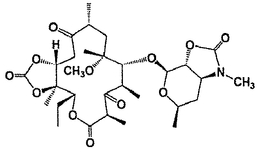
73 72 0.3 'Ex' means Example according to this invention. 'Ex' means Example according to this invention. - The deodorization step was performed using the reactor shown in
Fig. 1 . - The 3'-dimethylaminoacetophenone solution (solution A) containing the malodorous material was prepared referring to the method described in J. Am. Chem. Soc., vol. 94, p. 7586-7587 (1972).
- In a methylene chloride solvent at -20°C, Corey-Kim oxidation reaction was performed using 10 mL of 1-(3-dimethylaminophenyl)ethanol (0.3 mol/L), 0.391 g of dimethyl sulfide, 0.601 g of N-chlorosuccinimide, and 0.455 g of triethylamine, so that the desired ketone compound was obtained (reaction yield 89%) and then used. The oxidizing agent solution (solution B) used was so prepared that the amount of a sodium hypochlorite aqueous solution (concentration 13.3%) became 2.0 molar equivalent based on the amount of N-chlorosuccinimide. The solutions A and B were each sucked into a glass syringe and then fed to the microreactor using Syringe Pump model PHD-2000 manufactured by Harvard Apparatus. The solution A was supplied at a flow rate of 1.5 mL/min to the microreactor, and the solution B was supplied at a flow rate of 1.5 mL/min. In this process, the diameter of the flow passage (the inner diameter of the micromixer) was 0.25 mm at
sections 3 to 5 and 4 to 5, and immediately downstream ofpoint 5 in the micromixer ofFig. 1 . The retention time atsections 5 to 6 was 0.5 seconds. The reaction temperature was 30°C. After a waiting time of 3 minutes, the reaction liquid flowing out of the exit of the reactor was sampled for 15 seconds into a sampling tube containing 1 mL of pure water and then stirred at 25°C for 10 seconds. The reaction solution was analyzed using HPLC, in which quantitative analysis was performed by internal standardization using a standard material. As a result, the yield of the desired ketone compound (the total yield) was 88%, and no influence of the oxidation reaction on the substrate was observed. - Examples 49 to 51 were performed under the same conditions as those in Example 48, except that the kind of alcohol compound (reactant) was changed to that shown in Table 7 below.
- These results including that of Example 48 are comprehensively shown in 7.
- Note that "residual DMS" indicates the yield of the dimethyl sulfide residue (based on a theoretical value).
Table 7 Ex's Nos. Alcohol compound Reactant Carbonyl compound Product Yield (%) of carbonyl compound Total vield (%) Residual DMS (%) Ex 48 

89 88 0.9 Ex 49 

80 78 1.5 Ex 50 

75 73 2.3 Ex 51 

94 93 0.3 'Ex' means Example according to this invention. - The reaction step and the deodorization step were performed using the reactor shown in
Fig. 2 . - The solutions used were a methylene chloride solution of a mixture of 1-(3-dimethylaminophenyl)ethanol (0.06 M) and dimethyl sulfoxide (0.15 M) with the adjusted concentrations (solution A1), a trifluoroacetic anhydride/methylene chloride solution (0.15 M) (solution A2), a diisopropylethylamine/methylene chloride solution (0.18 M) (solution A3), and a solution (0.18 M) prepared in such a method that the amount of a sodium hypochlorite aqueous solution (concentration 13.3%) became 1.2 molar equivalent based on the amount of trifluoroacetic anhydride (solution B).
- Pump LC-20AT or LC-10Ai manufactured by SHIMADZU CORPORATION was used to feed the solutions A1, A2, A3, and B to the microreactor. The solutions A1 to A3 and B were supplied at a flow rate of 1.5 mL/min to the microreactor. In this process, the retention time at
sections 12 to 14, 15 to 17, and 18 to 20 in the micromixer ofFig. 2 were 0.05 seconds, 6.9 seconds, and 0.5 seconds, respectively. The diameter of the flow passage (the inner diameter of the micromixer) was 0.25 mm atsections 11 to 12, 13 to 12, 14 to 15, 16 to 15, 17 to 18, and 19 to 18, and immediately downstream ofpoints sections 7 to 14 and 8 to 14, and 30°C atsections 14 to 20, 9 to 20, and 10 to 20. After a waiting time of 3 minutes, the reaction liquid flowing out of the exit of the reactor was sampled for 15 seconds into a sampling tube containing 1 mL of pure water and then stirred at 25°C for 10 seconds. The reaction solution was analyzed using HPLC, in which quantitative analysis was performed by internal standardization using a standard material. As a result, the total yield of the desired ketone compound (yield after the deodorization step) was 90%, and no influence of the oxidation reaction on the substrate was observed. - Examples 53 to 55 were performed under the same conditions as those in Example 52, except that the kind of reactant was changed to that shown in Table 8 below.
- These results including that of Example 52 are comprehensively shown in Table 8.
- Note that "residual DMS" indicates the yield of the dimethyl sulfide residue (based on a theoretical value).
- Moreover, "Bz" represents a benzoyl group (-C(=O)-C6H5).
Table 8 Ex's Nos. Alcohol compound Reactant Carbonyl compound Product Total yield (%) Residual DMS (%) Ex 52 

90 0.3 Ex 53 

94 0.1 Ex 54 

87 0.4 Ex 55 

94 0.2 'Ex' means Example according to this invention. - Examples 56 to 60 were performed under the same conditions as those in Example 52, except that the compound for use in Example 55 was used as the reactant and the oxidizing agent was changed to that shown in Table 9 below. Examples 57 to 60 were performed using methylene chloride solutions. These results are comprehensively shown in Table 9.
Table 9 Ex's Nos. Kind of oxidizing agent Total yield (%) Residual DMS (%) Ex 56 Peracetic acid/ hydrogen peroxide solution 89 0.1 Ex 57 N-Chlorosuccinimide 94 0.1 Ex 58 N-Bromosuccinimide 93 0.1 Ex 59 1,3-Dichloro-5,5-dimethylhydantoin 92 0.1 Ex 60 1,3-Dibromo-5,5-dimethylhydantoin 92 0.1 'Ex' means Example according to this invention. - The reaction step and the deodorization step were performed using the reactor shown in
Fig. 2 . - The solutions used were a methylene chloride solution of a mixture of 1-(3-dimethylaminophenyl)ethanol (0.06 M) and dimethyl sulfide (0.13 M) with the adjusted concentrations (solution A1), a N-chlorosuccinimide/methylene chloride solution (0.09 M) (solution A2), a triethyl amine/methylene chloride solution (0.09 M) (solution A3), and a solution (0.18 M) prepared in such a method that the amount of a sodium hypochlorite aqueous solution (concentration 13.3%) became 2.0 molar equivalent based on the amount of N-chlorosuccinimide (solution B).
- Pump LC-20AT or LC-10Ai manufactured by SHIMADZU CORPORATION was used to feed the solutions A1, A2, A3, and B to the microreactor. The solutions A1 to A3 and B were supplied at a flow rate of 1.5 mL/min to the microreactor. In this process, the retention time at
sections 12 to 14, 15 to 17, and 18 to 20 in the micromixer ofFig. 2 were 10.5 seconds, 15.8 seconds, and 0.5 seconds, respectively. The diameter of the flow passage (the inner diameter of the micromixer) was 0.25 mm atsections 11 to 12, 13 to 12, 14 to 15, 16 to 15, 17 to 18, and 19 to 18, and immediately downstream ofpoints sections 7 to 14 and 8 to 14, and 30°C atsections 14 to 20, 9 to 20, and 10 to 20. After a waiting time of 3 minutes, the reaction liquid flowing out of the exit of the reactor was sampled for 15 seconds into a sampling tube containing 1 mL of pure water and then stirred at 25°C for 10 seconds. The reaction solution was analyzed using HPLC, in which quantitative analysis was performed by internal standardization using a standard material. As a result, the total yield of the desired ketone compound (yield after the deodorization step) was 90%, and no influence of the oxidation reaction on the substrate was observed. - Examples 62 to 66 were performed under the same conditions as those in Example 61, except that the reactant was changed to that shown in Table 10 below.
- These results including that of Example 61 are comprehensively shown in Table 10.
- Note that "residual DMS" indicates the yield of the dimethyl sulfide residue (based on a theoretical value)
Table 10 Ex's Nos. Alcohol compound Reactant Carbonyl compound Product Total yield (%) Residual DMS (%) Ex 61 
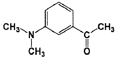
90 0.3 Ex 62 
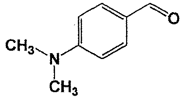
81 1.4 Ex 63 

75 2.1 'Ex' means Example according to this invention. Ex 64 

70 0.6 Ex 65 

92 0.8 Ex 66 

91 0.3 'Ex' means Example according to this invention. - Tables 1 to 10 described above show that when the deodorization step for removing, from a reaction liquid, a malodorous material generated or remaining in the reaction step was performed using a flow reaction in a flow passage, efficient deodorization treatment of merely the malodorous material was possible with no influence on the aldehyde or ketone compound produced in the reaction step.
-
- 1, 2
- Port for supplying a raw material to the microreactor
- 3, 4
- Port for supplying a raw material to the micromixer
- 5
- Start point of mixing of the solutions A and B
- 6
- Exit of the microreactor
- 7, 8, 9, 10
- Port for supplying a raw material to the microreactor
- 11, 13, 14, 16, 17, 19
- Port for supplying a raw material to the micromixer
- 12
- Mixing start point in a first step (a reaction between solutions A1 and A2)
- 15
- Mixing start point in a second step (a reaction with solution A3)
- 18
- Mixing start point in a third step (a reaction with solution B)
- 20
- Exit of the microreactor
Claims (13)
- A method of producing an aldehyde or ketone compound, which comprises a step of performing a deodorization step using a flow reaction in a flow passage to remove, from a reaction liquid, a malodorous material generated or remaining in a reaction step,
wherein the reaction step is an oxidation reaction that oxidizes an alcohol compound to form the aldehyde or ketone compound. - The production method according to Claim 1, wherein the reaction step is an oxidation reaction using a sulfur atom-containing organic compound.
- The production method according to Claim 1 or 2, wherein, in the reaction step, an alcohol compound having 2 to 50 carbon atoms is oxidized to produce an aldehyde or ketone compound having 2 to 50 carbon atoms.
- The production method according to Claim 2 or 3, wherein the oxidation reaction using a sulfur-atom-containing organic compound is an oxidation reaction using a dialkyl sulfoxide compound having 2 to 8 carbon atoms, and an acid anhydride having 4 to 10 carbon atoms or an acid halide having 2 to 7 carbon atoms.
- The production method according to any one of Claims 1 to 4, wherein the malodorous material is a dialkyl sulfide having 2 to 8 carbon atoms.
- The production method according to any one of Claims 1 to 5, wherein the deodorization step is an oxidation reaction of the malodorous material.
- The production method according to any one of Claims 1 to 6, wherein the deodorization step is an oxidation reaction in which the malodorous material is oxidized by using an oxidizing agent selected from the group consisting of hypochlorous acid or a salt thereof, a halogenating agent, and peracetic acid.
- The production method according to Claim 7, wherein the amount of the oxidizing agent to be used is 0.5 to 5.0 molar equivalents, based on the amount of the acid anhydride or the acid halide to be used in the reaction step.
- The production method according to any one of Claims 1 to 8, wherein the reaction temperature in the deodorization step is from -20°C to 60°C.
- The production method according to any one of Claims 1 to 9, wherein the time for which the deodorization step is retained in the flow passage (reaction time) is from 0.01 to 120 seconds.
- The production method according to any one of Claims 3 to 10, wherein the alcohol compound is a compound represented by Formula (A), and the organic compound is a compound represented by Formula (B):

- The production method according to any one of Claims 1 to 11, wherein the reaction step and the deodorization step are both flow reactions in the flow passage and performed sequentially.
- The production method according to any one of Claims 1 to 12, wherein the deodorization step is conducted in a microreactor.
Applications Claiming Priority (2)
| Application Number | Priority Date | Filing Date | Title |
|---|---|---|---|
| JP2015195375 | 2015-09-30 | ||
| PCT/JP2016/078623 WO2017057460A1 (en) | 2015-09-30 | 2016-09-28 | Method for producing organic compound |
Publications (3)
| Publication Number | Publication Date |
|---|---|
| EP3357898A1 EP3357898A1 (en) | 2018-08-08 |
| EP3357898A4 EP3357898A4 (en) | 2019-04-24 |
| EP3357898B1 true EP3357898B1 (en) | 2020-11-25 |
Family
ID=58427576
Family Applications (1)
| Application Number | Title | Priority Date | Filing Date |
|---|---|---|---|
| EP16851631.8A Active EP3357898B1 (en) | 2015-09-30 | 2016-09-28 | Method for producing organic compound |
Country Status (5)
| Country | Link |
|---|---|
| US (1) | US10351512B2 (en) |
| EP (1) | EP3357898B1 (en) |
| JP (1) | JP6888550B2 (en) |
| MX (1) | MX2018001968A (en) |
| WO (1) | WO2017057460A1 (en) |
Families Citing this family (2)
| Publication number | Priority date | Publication date | Assignee | Title |
|---|---|---|---|---|
| CN109232218B (en) * | 2018-09-20 | 2020-05-12 | 清华大学 | Method for preparing benzil by oxidizing benzoin in microreactor |
| WO2022146980A1 (en) * | 2020-12-28 | 2022-07-07 | Georgia Tech Research Corporation | Compositions and methods for inhibiting fibrosis, inflammation and cancer |
Family Cites Families (8)
| Publication number | Priority date | Publication date | Assignee | Title |
|---|---|---|---|---|
| US6267941B1 (en) * | 1997-01-08 | 2001-07-31 | Nec Corporation | Catalyst system for deodorization of a mixture of sulfur compounds and compounds such as aldehydes, alcohols and/or hydrocarbons |
| JPH10309443A (en) * | 1997-05-09 | 1998-11-24 | Tokyo Gas Co Ltd | Method for deodorizing combustion exhaust gas, catalyst and catalyst unit therefor |
| JP2003171332A (en) | 2001-11-30 | 2003-06-20 | Showa Denko Kk | Method for producing bisbenzyl compound |
| JP2003313151A (en) | 2002-04-23 | 2003-11-06 | Wako Pure Chem Ind Ltd | Method for oxidizing alcohol by using sulfur-containing compound |
| CA2505239A1 (en) | 2002-11-06 | 2004-05-21 | Kensuke Nagashima | Process for producing quinolinecarbaldehyde |
| PT1864987E (en) | 2004-02-06 | 2010-03-09 | Euro Celtique Sa | Methods for making 3-o protected morphinones and 3-o-protected morphinone dienol carboxylates |
| JP2006246855A (en) | 2005-03-14 | 2006-09-21 | Pokka Corp | Method for producing high-quality drink/food |
| JP2008214257A (en) | 2007-03-02 | 2008-09-18 | Hamamatsu Kagaku Gijutsu Kenkyu Shinkokai | Method for producing sulfoxide compound |
-
2016
- 2016-09-28 JP JP2017543485A patent/JP6888550B2/en active Active
- 2016-09-28 EP EP16851631.8A patent/EP3357898B1/en active Active
- 2016-09-28 MX MX2018001968A patent/MX2018001968A/en unknown
- 2016-09-28 WO PCT/JP2016/078623 patent/WO2017057460A1/en not_active Ceased
- 2016-09-28 US US15/751,217 patent/US10351512B2/en active Active
Non-Patent Citations (1)
| Title |
|---|
| None * |
Also Published As
| Publication number | Publication date |
|---|---|
| JP6888550B2 (en) | 2021-06-16 |
| EP3357898A1 (en) | 2018-08-08 |
| JPWO2017057460A1 (en) | 2018-08-09 |
| EP3357898A4 (en) | 2019-04-24 |
| MX2018001968A (en) | 2018-11-09 |
| US20180244604A1 (en) | 2018-08-30 |
| WO2017057460A1 (en) | 2017-04-06 |
| US10351512B2 (en) | 2019-07-16 |
Similar Documents
| Publication | Publication Date | Title |
|---|---|---|
| Hussain et al. | Journey describing applications of oxone in synthetic chemistry | |
| US6297403B1 (en) | Process for the preparation of aldehydes and ketones | |
| Rozen et al. | At Last, 1, 10‐Phenanthroline‐N, N′‐dioxide, A New Type of Helicene, has been Synthesized using HOF⋅ CH3CN | |
| EP3357898A1 (en) | Method for producing organic compound | |
| Yamansarov et al. | Synthesis and antimalarial activity of 3′-trifluoromethylated 1, 2, 4-trioxolanes and 1, 2, 4, 5-tetraoxane based on deoxycholic acid | |
| Zhang et al. | Visible light-induced aerobic dioxygenation of α, β-unsaturated amides/alkenes toward selective synthesis of β-oxy alcohols using rose bengal as a photosensitizer | |
| Vanoye et al. | Mechanistic insights into the aerobic oxidation of aldehydes: evidence of multiple reaction pathways during the liquid phase oxidation of 2-ethylhexanal | |
| Yue et al. | 1, 2‐(Hydr) oxy-trifluoromethylation of CC multiple bonds: Synthesis of β-trifluoromethyl alcohols and α-trifluoromethyl ketones | |
| Renar et al. | Activation of aqueous hydrogen peroxide for non-catalyzed dihydroperoxidation of ketones by azeotropic removal of water | |
| Hirano et al. | Radical addition of ethers to alkenes under dioxygen catalyzed by N-hydroxyphthalimide (NHPI)/Co (OAc) 2 | |
| Bradley et al. | Baeyer–Villiger oxidation under Payne epoxidation conditions | |
| Yuan et al. | A cooperation of ceric ammonium nitrate and N-hydroxyphthalimide in the aerobic oxidation from ketones to lactones/esters: Catalytic characterization and mechanistic investigation | |
| JP5679150B2 (en) | Method for producing pyruvic acid and esters thereof | |
| EP4302873A4 (en) | CATALYST, AND METHOD FOR PRODUCING COMPOUND BY GAS PHASE OXIDATION REACTION USING SAME | |
| Sauer et al. | Oxidative Formation of Disulfide Bonds by a Chemiluminescent 1, 2-Dioxetane under Mild Conditions | |
| EP3357908B1 (en) | Method for producing aldehyde compound or ketone compound | |
| Das et al. | Organic reactions in water: an efficient one-pot synthesis of acyloxiranes from Baylis–Hillman adducts using hypervalent iodine | |
| Shoji et al. | Chemistry of epoxyquinols A, B, and C and epoxytwinol A | |
| Takemoto et al. | CAN-mediated tandem 5-exo-cyclisation of tertiary aminocyclopropanes: novel accelerative effect of an N-benzyl group for oxidative ring-opening | |
| Zhao et al. | Amidoselenation of Alkenes Yielding the β-Amido-selenides through a Radical Pathway | |
| Xie et al. | Photo-induced synthesis of epoxy ketones via decatungstate-mediated aerobic epoxidations of α, β-unsaturated ketones under room temperature | |
| KR101693913B1 (en) | Continuous flow process for the preparation of sulphoxide compounds | |
| Ballistreri et al. | Selective oxidation reactions of diaryl-and dialkyldisulfides to sulfonic acids by CH3ReO3/hydrogen peroxide | |
| Liu et al. | Deconstructive diversification through CC single bond cleavage | |
| Saegusa et al. | Bromocyclization of Unsaturated Thioester and Access to Functionalized Sulfur-heterocycles |
Legal Events
| Date | Code | Title | Description |
|---|---|---|---|
| STAA | Information on the status of an ep patent application or granted ep patent |
Free format text: STATUS: THE INTERNATIONAL PUBLICATION HAS BEEN MADE |
|
| PUAI | Public reference made under article 153(3) epc to a published international application that has entered the european phase |
Free format text: ORIGINAL CODE: 0009012 |
|
| STAA | Information on the status of an ep patent application or granted ep patent |
Free format text: STATUS: REQUEST FOR EXAMINATION WAS MADE |
|
| 17P | Request for examination filed |
Effective date: 20171211 |
|
| AK | Designated contracting states |
Kind code of ref document: A1 Designated state(s): AL AT BE BG CH CY CZ DE DK EE ES FI FR GB GR HR HU IE IS IT LI LT LU LV MC MK MT NL NO PL PT RO RS SE SI SK SM TR |
|
| AX | Request for extension of the european patent |
Extension state: BA ME |
|
| DAV | Request for validation of the european patent (deleted) | ||
| DAX | Request for extension of the european patent (deleted) | ||
| A4 | Supplementary search report drawn up and despatched |
Effective date: 20190321 |
|
| RAP1 | Party data changed (applicant data changed or rights of an application transferred) |
Owner name: FUJIFILM WAKO PURE CHEMICAL CORPORATION |
|
| STAA | Information on the status of an ep patent application or granted ep patent |
Free format text: STATUS: EXAMINATION IS IN PROGRESS |
|
| 17Q | First examination report despatched |
Effective date: 20200213 |
|
| REG | Reference to a national code |
Ref country code: DE Ref legal event code: R079 Ref document number: 602016048771 Country of ref document: DE Free format text: PREVIOUS MAIN CLASS: C07B0033000000 Ipc: C07B0063020000 |
|
| GRAP | Despatch of communication of intention to grant a patent |
Free format text: ORIGINAL CODE: EPIDOSNIGR1 |
|
| STAA | Information on the status of an ep patent application or granted ep patent |
Free format text: STATUS: GRANT OF PATENT IS INTENDED |
|
| RIC1 | Information provided on ipc code assigned before grant |
Ipc: C07J 1/00 20060101ALI20200602BHEP Ipc: C07C 49/303 20060101ALI20200602BHEP Ipc: C07H 17/08 20060101ALI20200602BHEP Ipc: C07C 49/403 20060101ALI20200602BHEP Ipc: C07C 223/06 20060101ALI20200602BHEP Ipc: C07C 49/04 20060101ALI20200602BHEP Ipc: C07C 47/02 20060101ALI20200602BHEP Ipc: C07C 49/786 20060101ALI20200602BHEP Ipc: C07C 221/00 20060101ALI20200602BHEP Ipc: C07B 33/00 20060101ALI20200602BHEP Ipc: C07C 225/22 20060101ALI20200602BHEP Ipc: C07D 307/46 20060101ALI20200602BHEP Ipc: C07C 49/78 20060101ALI20200602BHEP Ipc: C07C 315/02 20060101ALI20200602BHEP Ipc: C07B 63/00 20060101ALI20200602BHEP Ipc: C07D 213/50 20060101ALI20200602BHEP Ipc: C07B 63/02 20060101AFI20200602BHEP Ipc: C07C 49/807 20060101ALI20200602BHEP Ipc: C07C 47/228 20060101ALI20200602BHEP Ipc: C07C 45/29 20060101ALI20200602BHEP |
|
| INTG | Intention to grant announced |
Effective date: 20200623 |
|
| RIN1 | Information on inventor provided before grant (corrected) |
Inventor name: KEMMOKU, AKIRA Inventor name: HAGA, YAYOI Inventor name: KAWAMOTO, FUMIO |
|
| GRAS | Grant fee paid |
Free format text: ORIGINAL CODE: EPIDOSNIGR3 |
|
| GRAA | (expected) grant |
Free format text: ORIGINAL CODE: 0009210 |
|
| STAA | Information on the status of an ep patent application or granted ep patent |
Free format text: STATUS: THE PATENT HAS BEEN GRANTED |
|
| AK | Designated contracting states |
Kind code of ref document: B1 Designated state(s): AL AT BE BG CH CY CZ DE DK EE ES FI FR GB GR HR HU IE IS IT LI LT LU LV MC MK MT NL NO PL PT RO RS SE SI SK SM TR |
|
| REG | Reference to a national code |
Ref country code: GB Ref legal event code: FG4D |
|
| REG | Reference to a national code |
Ref country code: CH Ref legal event code: EP |
|
| REG | Reference to a national code |
Ref country code: CH Ref legal event code: NV Representative=s name: VALIPAT S.A. C/O BOVARD SA NEUCHATEL, CH Ref country code: AT Ref legal event code: REF Ref document number: 1338102 Country of ref document: AT Kind code of ref document: T Effective date: 20201215 |
|
| REG | Reference to a national code |
Ref country code: DE Ref legal event code: R096 Ref document number: 602016048771 Country of ref document: DE |
|
| REG | Reference to a national code |
Ref country code: IE Ref legal event code: FG4D |
|
| REG | Reference to a national code |
Ref country code: AT Ref legal event code: MK05 Ref document number: 1338102 Country of ref document: AT Kind code of ref document: T Effective date: 20201125 |
|
| REG | Reference to a national code |
Ref country code: NL Ref legal event code: MP Effective date: 20201125 |
|
| PG25 | Lapsed in a contracting state [announced via postgrant information from national office to epo] |
Ref country code: NO Free format text: LAPSE BECAUSE OF FAILURE TO SUBMIT A TRANSLATION OF THE DESCRIPTION OR TO PAY THE FEE WITHIN THE PRESCRIBED TIME-LIMIT Effective date: 20210225 Ref country code: RS Free format text: LAPSE BECAUSE OF FAILURE TO SUBMIT A TRANSLATION OF THE DESCRIPTION OR TO PAY THE FEE WITHIN THE PRESCRIBED TIME-LIMIT Effective date: 20201125 Ref country code: PT Free format text: LAPSE BECAUSE OF FAILURE TO SUBMIT A TRANSLATION OF THE DESCRIPTION OR TO PAY THE FEE WITHIN THE PRESCRIBED TIME-LIMIT Effective date: 20210325 Ref country code: GR Free format text: LAPSE BECAUSE OF FAILURE TO SUBMIT A TRANSLATION OF THE DESCRIPTION OR TO PAY THE FEE WITHIN THE PRESCRIBED TIME-LIMIT Effective date: 20210226 Ref country code: FI Free format text: LAPSE BECAUSE OF FAILURE TO SUBMIT A TRANSLATION OF THE DESCRIPTION OR TO PAY THE FEE WITHIN THE PRESCRIBED TIME-LIMIT Effective date: 20201125 |
|
| PG25 | Lapsed in a contracting state [announced via postgrant information from national office to epo] |
Ref country code: BG Free format text: LAPSE BECAUSE OF FAILURE TO SUBMIT A TRANSLATION OF THE DESCRIPTION OR TO PAY THE FEE WITHIN THE PRESCRIBED TIME-LIMIT Effective date: 20210225 Ref country code: LV Free format text: LAPSE BECAUSE OF FAILURE TO SUBMIT A TRANSLATION OF THE DESCRIPTION OR TO PAY THE FEE WITHIN THE PRESCRIBED TIME-LIMIT Effective date: 20201125 Ref country code: PL Free format text: LAPSE BECAUSE OF FAILURE TO SUBMIT A TRANSLATION OF THE DESCRIPTION OR TO PAY THE FEE WITHIN THE PRESCRIBED TIME-LIMIT Effective date: 20201125 Ref country code: IS Free format text: LAPSE BECAUSE OF FAILURE TO SUBMIT A TRANSLATION OF THE DESCRIPTION OR TO PAY THE FEE WITHIN THE PRESCRIBED TIME-LIMIT Effective date: 20210325 Ref country code: AT Free format text: LAPSE BECAUSE OF FAILURE TO SUBMIT A TRANSLATION OF THE DESCRIPTION OR TO PAY THE FEE WITHIN THE PRESCRIBED TIME-LIMIT Effective date: 20201125 Ref country code: SE Free format text: LAPSE BECAUSE OF FAILURE TO SUBMIT A TRANSLATION OF THE DESCRIPTION OR TO PAY THE FEE WITHIN THE PRESCRIBED TIME-LIMIT Effective date: 20201125 |
|
| REG | Reference to a national code |
Ref country code: LT Ref legal event code: MG9D |
|
| PG25 | Lapsed in a contracting state [announced via postgrant information from national office to epo] |
Ref country code: HR Free format text: LAPSE BECAUSE OF FAILURE TO SUBMIT A TRANSLATION OF THE DESCRIPTION OR TO PAY THE FEE WITHIN THE PRESCRIBED TIME-LIMIT Effective date: 20201125 |
|
| PG25 | Lapsed in a contracting state [announced via postgrant information from national office to epo] |
Ref country code: CZ Free format text: LAPSE BECAUSE OF FAILURE TO SUBMIT A TRANSLATION OF THE DESCRIPTION OR TO PAY THE FEE WITHIN THE PRESCRIBED TIME-LIMIT Effective date: 20201125 Ref country code: EE Free format text: LAPSE BECAUSE OF FAILURE TO SUBMIT A TRANSLATION OF THE DESCRIPTION OR TO PAY THE FEE WITHIN THE PRESCRIBED TIME-LIMIT Effective date: 20201125 Ref country code: SM Free format text: LAPSE BECAUSE OF FAILURE TO SUBMIT A TRANSLATION OF THE DESCRIPTION OR TO PAY THE FEE WITHIN THE PRESCRIBED TIME-LIMIT Effective date: 20201125 Ref country code: LT Free format text: LAPSE BECAUSE OF FAILURE TO SUBMIT A TRANSLATION OF THE DESCRIPTION OR TO PAY THE FEE WITHIN THE PRESCRIBED TIME-LIMIT Effective date: 20201125 Ref country code: SK Free format text: LAPSE BECAUSE OF FAILURE TO SUBMIT A TRANSLATION OF THE DESCRIPTION OR TO PAY THE FEE WITHIN THE PRESCRIBED TIME-LIMIT Effective date: 20201125 Ref country code: RO Free format text: LAPSE BECAUSE OF FAILURE TO SUBMIT A TRANSLATION OF THE DESCRIPTION OR TO PAY THE FEE WITHIN THE PRESCRIBED TIME-LIMIT Effective date: 20201125 |
|
| REG | Reference to a national code |
Ref country code: DE Ref legal event code: R097 Ref document number: 602016048771 Country of ref document: DE |
|
| PG25 | Lapsed in a contracting state [announced via postgrant information from national office to epo] |
Ref country code: DK Free format text: LAPSE BECAUSE OF FAILURE TO SUBMIT A TRANSLATION OF THE DESCRIPTION OR TO PAY THE FEE WITHIN THE PRESCRIBED TIME-LIMIT Effective date: 20201125 |
|
| PLBE | No opposition filed within time limit |
Free format text: ORIGINAL CODE: 0009261 |
|
| STAA | Information on the status of an ep patent application or granted ep patent |
Free format text: STATUS: NO OPPOSITION FILED WITHIN TIME LIMIT |
|
| PG25 | Lapsed in a contracting state [announced via postgrant information from national office to epo] |
Ref country code: NL Free format text: LAPSE BECAUSE OF FAILURE TO SUBMIT A TRANSLATION OF THE DESCRIPTION OR TO PAY THE FEE WITHIN THE PRESCRIBED TIME-LIMIT Effective date: 20201125 Ref country code: AL Free format text: LAPSE BECAUSE OF FAILURE TO SUBMIT A TRANSLATION OF THE DESCRIPTION OR TO PAY THE FEE WITHIN THE PRESCRIBED TIME-LIMIT Effective date: 20201125 Ref country code: IT Free format text: LAPSE BECAUSE OF FAILURE TO SUBMIT A TRANSLATION OF THE DESCRIPTION OR TO PAY THE FEE WITHIN THE PRESCRIBED TIME-LIMIT Effective date: 20201125 |
|
| 26N | No opposition filed |
Effective date: 20210826 |
|
| PG25 | Lapsed in a contracting state [announced via postgrant information from national office to epo] |
Ref country code: SI Free format text: LAPSE BECAUSE OF FAILURE TO SUBMIT A TRANSLATION OF THE DESCRIPTION OR TO PAY THE FEE WITHIN THE PRESCRIBED TIME-LIMIT Effective date: 20201125 |
|
| PG25 | Lapsed in a contracting state [announced via postgrant information from national office to epo] |
Ref country code: ES Free format text: LAPSE BECAUSE OF FAILURE TO SUBMIT A TRANSLATION OF THE DESCRIPTION OR TO PAY THE FEE WITHIN THE PRESCRIBED TIME-LIMIT Effective date: 20201125 |
|
| REG | Reference to a national code |
Ref country code: BE Ref legal event code: MM Effective date: 20210930 |
|
| PG25 | Lapsed in a contracting state [announced via postgrant information from national office to epo] |
Ref country code: IS Free format text: LAPSE BECAUSE OF FAILURE TO SUBMIT A TRANSLATION OF THE DESCRIPTION OR TO PAY THE FEE WITHIN THE PRESCRIBED TIME-LIMIT Effective date: 20210325 Ref country code: MC Free format text: LAPSE BECAUSE OF FAILURE TO SUBMIT A TRANSLATION OF THE DESCRIPTION OR TO PAY THE FEE WITHIN THE PRESCRIBED TIME-LIMIT Effective date: 20201125 |
|
| PG25 | Lapsed in a contracting state [announced via postgrant information from national office to epo] |
Ref country code: LU Free format text: LAPSE BECAUSE OF NON-PAYMENT OF DUE FEES Effective date: 20210928 Ref country code: IE Free format text: LAPSE BECAUSE OF NON-PAYMENT OF DUE FEES Effective date: 20210928 Ref country code: BE Free format text: LAPSE BECAUSE OF NON-PAYMENT OF DUE FEES Effective date: 20210930 |
|
| P01 | Opt-out of the competence of the unified patent court (upc) registered |
Effective date: 20230512 |
|
| PG25 | Lapsed in a contracting state [announced via postgrant information from national office to epo] |
Ref country code: CY Free format text: LAPSE BECAUSE OF FAILURE TO SUBMIT A TRANSLATION OF THE DESCRIPTION OR TO PAY THE FEE WITHIN THE PRESCRIBED TIME-LIMIT Effective date: 20201125 |
|
| PG25 | Lapsed in a contracting state [announced via postgrant information from national office to epo] |
Ref country code: HU Free format text: LAPSE BECAUSE OF FAILURE TO SUBMIT A TRANSLATION OF THE DESCRIPTION OR TO PAY THE FEE WITHIN THE PRESCRIBED TIME-LIMIT; INVALID AB INITIO Effective date: 20160928 |
|
| PG25 | Lapsed in a contracting state [announced via postgrant information from national office to epo] |
Ref country code: MK Free format text: LAPSE BECAUSE OF FAILURE TO SUBMIT A TRANSLATION OF THE DESCRIPTION OR TO PAY THE FEE WITHIN THE PRESCRIBED TIME-LIMIT Effective date: 20201125 |
|
| PG25 | Lapsed in a contracting state [announced via postgrant information from national office to epo] |
Ref country code: TR Free format text: LAPSE BECAUSE OF FAILURE TO SUBMIT A TRANSLATION OF THE DESCRIPTION OR TO PAY THE FEE WITHIN THE PRESCRIBED TIME-LIMIT Effective date: 20201125 |
|
| PG25 | Lapsed in a contracting state [announced via postgrant information from national office to epo] |
Ref country code: MT Free format text: LAPSE BECAUSE OF FAILURE TO SUBMIT A TRANSLATION OF THE DESCRIPTION OR TO PAY THE FEE WITHIN THE PRESCRIBED TIME-LIMIT Effective date: 20201125 |
|
| REG | Reference to a national code |
Ref country code: CH Ref legal event code: U11 Free format text: ST27 STATUS EVENT CODE: U-0-0-U10-U11 (AS PROVIDED BY THE NATIONAL OFFICE) Effective date: 20251001 |
|
| PGFP | Annual fee paid to national office [announced via postgrant information from national office to epo] |
Ref country code: DE Payment date: 20250805 Year of fee payment: 10 |
|
| PGFP | Annual fee paid to national office [announced via postgrant information from national office to epo] |
Ref country code: GB Payment date: 20250807 Year of fee payment: 10 |
|
| PGFP | Annual fee paid to national office [announced via postgrant information from national office to epo] |
Ref country code: FR Payment date: 20250808 Year of fee payment: 10 |
|
| PGFP | Annual fee paid to national office [announced via postgrant information from national office to epo] |
Ref country code: CH Payment date: 20251001 Year of fee payment: 10 |