EP3357811A1 - Atterrisseur d`aeronef - Google Patents
Atterrisseur d`aeronef Download PDFInfo
- Publication number
- EP3357811A1 EP3357811A1 EP18154003.0A EP18154003A EP3357811A1 EP 3357811 A1 EP3357811 A1 EP 3357811A1 EP 18154003 A EP18154003 A EP 18154003A EP 3357811 A1 EP3357811 A1 EP 3357811A1
- Authority
- EP
- European Patent Office
- Prior art keywords
- axle
- magnetic
- landing gear
- aircraft landing
- gear according
- Prior art date
- Legal status (The legal status is an assumption and is not a legal conclusion. Google has not performed a legal analysis and makes no representation as to the accuracy of the status listed.)
- Granted
Links
Images


Classifications
-
- G—PHYSICS
- G01—MEASURING; TESTING
- G01G—WEIGHING
- G01G19/00—Weighing apparatus or methods adapted for special purposes not provided for in the preceding groups
- G01G19/08—Weighing apparatus or methods adapted for special purposes not provided for in the preceding groups for incorporation in vehicles
- G01G19/12—Weighing apparatus or methods adapted for special purposes not provided for in the preceding groups for incorporation in vehicles having electrical weight-sensitive devices
-
- B—PERFORMING OPERATIONS; TRANSPORTING
- B64—AIRCRAFT; AVIATION; COSMONAUTICS
- B64C—AEROPLANES; HELICOPTERS
- B64C25/00—Alighting gear
- B64C25/32—Alighting gear characterised by elements which contact the ground or similar surface
- B64C25/34—Alighting gear characterised by elements which contact the ground or similar surface wheeled type, e.g. multi-wheeled bogies
-
- B—PERFORMING OPERATIONS; TRANSPORTING
- B64—AIRCRAFT; AVIATION; COSMONAUTICS
- B64C—AEROPLANES; HELICOPTERS
- B64C25/00—Alighting gear
- B64C25/001—Devices not provided for in the groups B64C25/02 - B64C25/68
-
- B—PERFORMING OPERATIONS; TRANSPORTING
- B64—AIRCRAFT; AVIATION; COSMONAUTICS
- B64C—AEROPLANES; HELICOPTERS
- B64C25/00—Alighting gear
- B64C25/32—Alighting gear characterised by elements which contact the ground or similar surface
- B64C25/34—Alighting gear characterised by elements which contact the ground or similar surface wheeled type, e.g. multi-wheeled bogies
- B64C25/36—Arrangements or adaptations of wheels, tyres or axles in general
-
- B—PERFORMING OPERATIONS; TRANSPORTING
- B64—AIRCRAFT; AVIATION; COSMONAUTICS
- B64D—EQUIPMENT FOR FITTING IN OR TO AIRCRAFT; FLIGHT SUITS; PARACHUTES; ARRANGEMENT OR MOUNTING OF POWER PLANTS OR PROPULSION TRANSMISSIONS IN AIRCRAFT
- B64D45/00—Aircraft indicators or protectors not otherwise provided for
-
- B—PERFORMING OPERATIONS; TRANSPORTING
- B64—AIRCRAFT; AVIATION; COSMONAUTICS
- B64D—EQUIPMENT FOR FITTING IN OR TO AIRCRAFT; FLIGHT SUITS; PARACHUTES; ARRANGEMENT OR MOUNTING OF POWER PLANTS OR PROPULSION TRANSMISSIONS IN AIRCRAFT
- B64D47/00—Equipment not otherwise provided for
-
- G—PHYSICS
- G01—MEASURING; TESTING
- G01B—MEASURING LENGTH, THICKNESS OR SIMILAR LINEAR DIMENSIONS; MEASURING ANGLES; MEASURING AREAS; MEASURING IRREGULARITIES OF SURFACES OR CONTOURS
- G01B7/00—Measuring arrangements characterised by the use of electric or magnetic techniques
- G01B7/16—Measuring arrangements characterised by the use of electric or magnetic techniques for measuring the deformation in a solid, e.g. by resistance strain gauge
- G01B7/24—Measuring arrangements characterised by the use of electric or magnetic techniques for measuring the deformation in a solid, e.g. by resistance strain gauge using change in magnetic properties
-
- G—PHYSICS
- G01—MEASURING; TESTING
- G01G—WEIGHING
- G01G19/00—Weighing apparatus or methods adapted for special purposes not provided for in the preceding groups
- G01G19/02—Weighing apparatus or methods adapted for special purposes not provided for in the preceding groups for weighing wheeled or rolling bodies, e.g. vehicles
- G01G19/07—Weighing apparatus or methods adapted for special purposes not provided for in the preceding groups for weighing wheeled or rolling bodies, e.g. vehicles for weighing aircraft
-
- G—PHYSICS
- G01—MEASURING; TESTING
- G01G—WEIGHING
- G01G3/00—Weighing apparatus characterised by the use of elastically-deformable members, e.g. spring balances
- G01G3/12—Weighing apparatus characterised by the use of elastically-deformable members, e.g. spring balances wherein the weighing element is in the form of a solid body stressed by pressure or tension during weighing
- G01G3/15—Weighing apparatus characterised by the use of elastically-deformable members, e.g. spring balances wherein the weighing element is in the form of a solid body stressed by pressure or tension during weighing measuring variations of magnetic properties
-
- G—PHYSICS
- G01—MEASURING; TESTING
- G01G—WEIGHING
- G01G7/00—Weighing apparatus wherein the balancing is effected by magnetic, electromagnetic, or electrostatic action, or by means not provided for in the preceding groups
- G01G7/02—Weighing apparatus wherein the balancing is effected by magnetic, electromagnetic, or electrostatic action, or by means not provided for in the preceding groups by electromagnetic action
-
- G—PHYSICS
- G01—MEASURING; TESTING
- G01M—TESTING STATIC OR DYNAMIC BALANCE OF MACHINES OR STRUCTURES; TESTING OF STRUCTURES OR APPARATUS, NOT OTHERWISE PROVIDED FOR
- G01M1/00—Testing static or dynamic balance of machines or structures
- G01M1/12—Static balancing; Determining position of centre of gravity
- G01M1/122—Determining position of centre of gravity
- G01M1/125—Determining position of centre of gravity of aircraft
Definitions
- the LVDT sensors are positioned on an inside diameter of the axle.
- the space available inside the axle is very small, and it is then necessary to use LVDT sensors of very small size, which are fragile, imprecise and expensive.
- the assembly and disassembly of LVDT sensors are complex to achieve because, once again, the smallness of the axle.
- the reduced available space makes it necessary to position the LVDT sensors on the same support. Seizure of one of the LVDT sensors results in the loss of information produced by other LVDT sensors.
- the object of the invention is to overcome the disadvantages of the methods mentioned earlier.
- an aircraft undercarriage comprising an axle for carrying at least one wheel, the aircraft undercarriage further comprising a magnetic measurement target and at least one magnetic displacement sensor cooperating with the magnetic measurement target for measuring axle bending, the magnetic measurement target having a body extending inside the axle, the body including a fastening end attached to one end of the axle and a target surface that extends on an inner surface of the body, the magnetic displacement sensor being positioned within the axle to measure a displacement of the target surface.
- the positioning of the magnetic measurement target inside the axle makes it possible to increase the space available for the integration of the magnetic displacement sensor that cooperates with the magnetic measurement target.
- This integration also facilitates the maintenance operations performed for the magnetic measurement target and the magnetic displacement sensor.
- the aircraft undercarriage 1 is here an auxiliary undercarriage which comprises a leg 2 comprising a box 3 in which slides a sliding rod 4.
- An axle 5 carrying two wheels 6 is positioned at the bottom of the sliding rod 4.
- Two magnetic measurement targets and magnetic displacement sensors are used here to detect a deformation of the axle 5 so as to reliably determine whether, at the time of landing, the wheels 6 have touched the ground or not.
- the magnetic measurement target 10 comprises a body 11 which comprises a fixing end 12 and a running part 13.
- the fastening end 12 has successively and along the length of the body 11 a cylindrical outer surface portion 14, a hexagonal outer surface portion 15, a threaded portion 16, a first groove 17, an outer chamfer 18, a second groove 19 and a third groove 20 of square section.
- a seal is positioned in the third groove 20.
- a through orifice 22 is located in the first groove 17.
- the current portion 13 of the body 11 has a cylindrical shape of X axis partially recessed.
- a slot 23 is made in the common portion 13 of the body 11.
- the slot 23 extends in an axial direction, parallel to the axis X, over almost the entire length of the current portion 13.
- the slot 23 separates between them two longitudinal portions of body 25.
- Each longitudinal portion of body 25 has at a free end a flat target surface 26, which extends on an inner surface of the longitudinal portion of body 25; say with regard to the X axis.
- the two target surfaces 26 are thus separated only by the slot 23.
- the cylindrical shape partly recessed from the current portion 13 is such that no material (of the body 11) extends with respect to the target surfaces 26.
- each magnetic measuring target 10 being positioned on one side of the axle 5.
- each magnetic measuring target 10 requires fixing means which comprise a nut 30 and a ring 31.
- the body 11 of the measurement target 10 is inserted inside the axle 5, slightly beyond its final position.
- the rod 31 is then positioned against the outer chamfer 18. Then, the body 11 is moved outwardly of the axle 5 to be positioned in its final position.
- the rod 31 is then partially positioned in a groove 35 made for this purpose on an inner surface of the axle 5.
- the outer chamfer 18 presses on the rod 31 and increases the diameter of the ring 31 which still sinks in the throat 35.
- the nut 30 is then screwed onto the threaded portion 16 of the body 11. A portion 36 of the nut 30 is inserted inside the axle 5. The more the nut 30 is screwed, the more the rod 31 sinks into the groove 35.
- the ring 31 and the groove 35 form an axial abutment for the body 11 of the magnetic measurement target 10.
- the outer diameter of the nut 30, at the portion 36, is very close to the internal diameter of the axle 5 at its end, so that a first short centering of the magnetic measurement target 10 inside the axle 5 is obtained via the nut 30, the body 11 and the axle 5.
- the seal and the body surfaces 37 located on either side of the third groove 20 also have an outer diameter very close to the internal diameter of the axle 5 at this location, so that a second centering short of the magnetic measurement target 10 inside the axle 5 is obtained via the seal, the body surfaces 37 and the axle 5.
- a wheel nut 33 is screwed onto a threaded portion 38 of an outer surface of the axle 5.
- a bolt 32 which stops the wheel nut 33 in rotation, is inserted through a hole passing through the nut. wheel 33, through a hole through the axle 5, and through the through hole 22 located in the first groove 17 of the body 11.
- the bolt 32 has at one of its ends a radial through hole 40 through which is likely to travel a wire to brake.
- the thread to be braked can be replaced by a cotter pin for braking a nut (not shown in the figures).
- the link without play between the axle 5 and the magnetic measurement target 10, resulting from these clearance-free fixing means, makes it possible to produce a displacement of the target surfaces 26 representative of a movement the end of the axle 5 to which is fixed the body 11 of the magnetic measurement target 10.
- a bending of the axle 5 causes a rotation of the magnetic measurement targets 10 and thus the target surfaces 26.
- the displacement of the target surfaces 26 is amplified relative to the movement of the end of the axle 5 to which is fixed the body 11, due to the distance between the target surfaces 26 and the end of the axle (and therefore because of the length of the current portion 13 of the body 11).
- Each magnetic measurement target 10 is included in a magnetic measuring device which, in addition to the magnetic measurement target 10, comprises at least two magnetic displacement sensors, in this case a set of four magnetic displacement sensors.
- the magnetic displacement sensors used here are LVDT sensors 41.
- the magnetic measurement target is therefore associated with a set of four LVDT sensors 41.
- the four LVDT sensors 41 comprise two LVDT sensors 41 intended to cooperate with one of the two target surfaces 26, and two LVDT sensors 41 intended to cooperate with the other of the two target surfaces 26.
- Each LVDT sensor 41 has a measurement end comprising a probe 42 which is in contact with one of the target surfaces 26 when the measuring target magnetic 10 and thus said target surface 26 is rotated. A bending of the axle 5 resulting from the contact of the wheels 6 with the ground is thus detected.
- Each set of four LVDT sensors 41 associated with a magnetic measurement target 10 (two LVDT sensors 41 per target surface 26 of the magnetic measurement target 10) is mounted on a sensor support 43.
- Wires 44 connected to the LVDT sensors 41 and for transmitting to a calculator or data concentrator the measurements produced by the LVDT sensors 41, traveling from each sensor support 43.
- the axle 5 comprises an axle pot, which is a central portion 45 of the axle 5 fixed to the sliding rod 4 at a lower end 46 of the sliding rod 4.
- the central portion 45 of the axle 5 comprises two lower openings 48 for accessing the interior of the axle 5.
- Each sensor support 43 is fixed to the central portion 45 and extends through one of the lower openings 48.
- the LVDT sensors are thus introduced inside the central portion 45 of the axle 5.
- the sensors LVDT 41 therefore extend inside the central portion 45 of the axle 5 and are positioned in such a way that the measurement ends of the LVDT sensors 41 are located in close proximity or in contact with the target surfaces 26, so that measure a displacement of the target surfaces 26.
- a cover 47 protects the LVDT sensors 41.
- This configuration makes it easy to mount, dismantle and replace the LVDT 41 sensors, since it is sufficient, to access the LVDT sensors 41, to disassemble the cover 47. It is therefore not necessary to access the interior. axle 5. It is thus easier to carry out the maintenance operations carried out on the magnetic measuring devices (each comprising a magnetic measurement target 10 and a set of four LVDT sensors 41).
- This configuration also makes it possible to process the magnetic measurement targets 10 and the LVDT sensors 41 (or, more precisely here, the sets of four LVDT sensors 41) as LRUs (for Line-Replacable Unit ), ie as independent equipment that can be monitored, replaced, stored individually. Once again the maintenance operations implemented on the magnetic measuring devices are facilitated.
- LRUs for Line-Replacable Unit
- the invention applies, of course, to any type of undercarriage (auxiliary, main), and in particular to undercarriages carrying a number of wheels different from two (for example, to a landing gear carrying a single wheel).
- Magnetic displacement sensors are not necessarily LVDT sensors. Any type of sensor can be used (eg Hall effect sensors).
- LVDT sensors detect “only” whether the wheels have touched the ground or not
- magnetic displacement sensors could of course also accurately measure the amplitude of the displacement undergone by the target surfaces and the axle.
- the magnetic measuring device including the magnetic measurement target and the LVDT sensors is used to detect whether the wheels have touched the ground or not.
- the magnetic measuring device could also be used to implement different functions, for example a health monitoring function (also called a conditional maintenance or predictive maintenance function), or a weight and balance function (mass evaluation). and the centering of the aircraft), or a function of measuring a braking force via a measurement of flexion or torsion of the axle.
Landscapes
- Engineering & Computer Science (AREA)
- Aviation & Aerospace Engineering (AREA)
- Physics & Mathematics (AREA)
- General Physics & Mathematics (AREA)
- Mechanical Engineering (AREA)
- Electromagnetism (AREA)
- Measurement Of Length, Angles, Or The Like Using Electric Or Magnetic Means (AREA)
Abstract
Description
- Plusieurs méthodes ont été envisagées pour déterminer de manière fiable si, au moment d'un atterrissage, des roues portées par un atterrisseur d'aéronef ont ou non touché le sol.
- On a notamment envisagé de mesurer la pression d'un amortisseur d'une jambe de l'atterrisseur, ou bien de mesurer un déplacement d'une tige coulissante de la jambe de l'atterrisseur. Cependant, l'amortisseur de la jambe de l'atterrisseur présente un seuil de déplacement et un seuil d'enfoncement qui rendent ces solutions inefficaces et inappropriées.
- On a aussi envisagé d'intégrer, à l'intérieur d'un essieu de l'atterrisseur portant les roues, des capteurs de déplacement, et notamment des capteurs magnétiques de déplacement de type LVDT (pour Linear Variable Differential Transformer, en anglais). Les capteurs LVDT sont positionnés sur un diamètre interne de l'essieu.
- Cependant, l'espace disponible à l'intérieur de l'essieu est très réduit, et il convient alors d'utiliser des capteurs LVDT de très faible dimension, qui sont fragiles, peu précis et coûteux. Par ailleurs, le montage et le démontage des capteurs LVDT sont complexes à réaliser du fait, une fois encore, de l'exiguïté de l'essieu. Enfin, l'espace disponible réduit oblige à positionner les capteurs LVDT sur un même support. Un grippage de l'un des capteurs LVDT entraîne ainsi la perte des informations produites par les autres capteurs LVDT.
- L'invention a pour objet de pallier les inconvénients des méthodes évoquées plus tôt.
- En vue de la réalisation de ce but, on propose un atterrisseur d'aéronef comportant un essieu pour porter au moins une roue, l'atterrisseur d'aéronef comprenant en outre une cible de mesure magnétique et au moins un capteur magnétique de déplacement coopérant avec la cible de mesure magnétique pour mesurer une flexion de l'essieu, la cible de mesure magnétique comportant un corps qui s'étend à l'intérieur de l'essieu, le corps comprenant une extrémité de fixation fixée à une extrémité de l'essieu et une surface cible qui s'étend sur une surface interne du corps, le capteur magnétique de déplacement étant positionné à l'intérieur de l'essieu pour mesurer un déplacement de la surface cible.
- Le positionnement de la cible de mesure magnétique à l'intérieur de l'essieu permet d'augmenter l'espace disponible pour l'intégration du capteur magnétique de déplacement qui coopère avec la cible de mesure magnétique.
- Cette intégration permet en outre de faciliter les opérations de maintenance réalisées pour la cible de mesure magnétique et pour le capteur magnétique de déplacement.
- Enfin, dans le cas où plusieurs capteurs magnétiques de déplacement sont utilisés, l'augmentation de l'espace disponible permet de positionner les capteurs magnétiques de déplacement sur des supports différents, et donc d'augmenter la fiabilité des mesures.
- L'invention sera mieux comprise à la lumière de la description qui suit d'un mode de mise en oeuvre particulier non limitatif de l'invention.
- Il sera fait référence aux dessins annexés, parmi lesquels :
- la
figure 1 représente une jambe d'un atterrisseur d'aéronef selon l'invention ; - la
figure 2 représente une cible de mesure magnétique et des capteurs LVDT coopérant avec la cible de mesure magnétique ; - la
figure 3 représente deux cibles de mesure magnétique et des capteurs LVDT intégrés dans un essieu de l'atterrisseur d'aéronef selon l'invention ; - la
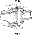
figure 4 est un agrandissement de lafigure 3 en bout d'essieu. - En référence à la
figure 1 , l'atterrisseur d'aéronef 1 selon l'invention est ici un atterrisseur auxiliaire qui comporte une jambe 2 comprenant un caisson 3 dans lequel coulisse une tige coulissante 4. - Un essieu 5 portant deux roues 6 est positionné au bas de la tige coulissante 4.
- Deux cibles de mesure magnétique et des capteurs magnétiques de déplacement sont utilisés ici pour détecter une déformation de l'essieu 5 de manière à déterminer de manière fiable si, au moment d'un atterrissage, les roues 6 ont ou non touché le sol.
- En référence à la
figure 2 , la cible de mesure magnétique 10 comporte un corps 11 qui comprend une extrémité de fixation 12 et une partie courante 13. - L'extrémité de fixation 12 présente successivement et selon la longueur du corps 11 une portion de surface extérieure cylindrique 14, une portion de surface extérieure hexagonale 15, une portion filetée 16, une première gorge 17, un chanfrein externe 18, une deuxième gorge 19 et une troisième gorge 20 de section carrée. Un joint d'étanchéité, non représenté sur les figures, est positionné dans la troisième gorge 20. Un orifice traversant 22 est situé dans la première gorge 17.
- La portion courante 13 du corps 11 présente une forme cylindrique d'axe X évidée partiellement.
- Une fente 23 est pratiquée dans la portion courante 13 du corps 11. La fente 23 s'étend selon une direction axiale, parallèlement à l'axe X, sur presque toute la longueur de la portion courante 13.
- La fente 23 sépare entre elles deux portions longitudinales de corps 25. Chaque portion longitudinale de corps 25 présente à une extrémité libre une surface cible plane 26, qui s'étend sur une surface interne de la portion longitudinale de corps 25, c'est à dire au regard de l'axe X.
- Les deux surfaces cibles 26 sont ainsi séparées uniquement par la fente 23. La forme cylindrique évidée partiellement de la portion courante 13 est telle qu'aucune matière (du corps 11) ne s'étend au regard des surfaces cibles 26.
- En référence aux
figures 3 et4 , deux cibles de mesure magnétique 10 sont intégrées dans l'essieu 5, chaque cible de mesure magnétique 10 étant positionnée d'un côté de l'essieu 5. - Le montage de chaque cible de mesure magnétique 10 requiert des moyens de fixation qui comprennent un écrou 30 et un jonc 31.
- Le corps 11 de la cible de mesure 10 est inséré à l'intérieur de l'essieu 5, légèrement au-delà de sa position finale. Le jonc 31 est alors positionné contre le chanfrein externe 18. Puis, le corps 11 est reculé vers l'extérieur de l'essieu 5 pour être positionné dans sa position finale.
- Le jonc 31 se positionne alors partiellement dans une gorge 35 pratiquée à cet effet sur une surface interne de l'essieu 5. Lorsque le corps 11 recule vers l'extérieur de l'essieu 5, le chanfrein externe 18 appuie sur le jonc 31 et vient augmenter le diamètre du jonc 31 qui s'enfonce encore dans la gorge 35.
- L'écrou 30 est alors vissé sur la portion filetée 16 du corps 11. Une portion 36 de l'écrou 30 est insérée à l'intérieur de l'essieu 5. Plus l'écrou 30 est vissé, plus le jonc 31 s'enfonce dans la gorge 35.
- Le jonc 31 et la gorge 35 forment une butée axiale pour le corps 11 de la cible de mesure magnétique 10.
- Le diamètre extérieur de l'écrou 30, au niveau de la portion 36, est très proche du diamètre interne de l'essieu 5 à son extrémité, de sorte qu'un premier centrage court de la cible de mesure magnétique 10 à l'intérieur de l'essieu 5 est obtenu via l'écrou 30, le corps 11 et l'essieu 5.
- Le joint d'étanchéité et les surfaces de corps 37 situées de part et d'autre de la troisième gorge 20 présentent aussi un diamètre extérieur très proche du diamètre interne de l'essieu 5 à cet endroit, de sorte qu'un deuxième centrage court de la cible de mesure magnétique 10 à l'intérieur de l'essieu 5 est obtenu via le joint d'étanchéité, les surfaces de corps 37 et l'essieu 5.
- Un écrou de roue 33 est vissé sur une portion filetée 38 d'une surface externe de l'essieu 5. Un boulon 32, qui arrête en rotation l'écrou de roue 33, est insérée au travers d'un orifice traversant l'écrou de roue 33, au travers d'un orifice traversant l'essieu 5, et au travers de l'orifice traversant 22 situé dans la première gorge 17 du corps 11.
- Le boulon 32 présente au niveau de l'une de ses extrémités un orifice traversant radial 40 au travers duquel est susceptible de cheminer un fil à freiner.
- Le fil à freiner peut être remplacé par une goupille fendue pour le freinage d'un écrou (non représenté sur les figures).
- L'écrou 30, le jonc 31, la gorge 35 pratiquée sur la surface interne de l'essieu 5, ainsi que l'extrémité de fixation 12 du corps 11, forment donc des moyens de fixation sans jeu du corps 11 et donc de la cible de mesure magnétique 10 à l'essieu 5.
- Ainsi, pour chaque cible de mesure magnétique 10, la liaison sans jeu entre l'essieu 5 et la cible de mesure magnétique 10, résultant de ces moyens de fixation sans jeu, permet de produire un déplacement des surfaces cibles 26 représentatif d'un mouvement de l'extrémité de l'essieu 5 à laquelle est fixé le corps 11 de la cible de mesure magnétique 10. En particulier, une flexion de l'essieu 5 entraîne une rotation des cibles de mesure magnétiques 10 et donc des surfaces cibles 26.
- Le déplacement des surfaces cibles 26 est amplifié par rapport au mouvement de l'extrémité de l'essieu 5 à laquelle est fixé le corps 11, du fait de la distance entre les surfaces cibles 26 et l'extrémité de l'essieu (et donc du fait de la longueur de la partie courante 13 du corps 11).
- Chaque cible de mesure magnétique 10 est incluse dans un dispositif de mesure magnétique qui, outre la cible de mesure magnétique 10, comprend au moins deux capteurs magnétiques de déplacement, en l'occurrence un ensemble de quatre capteurs magnétiques de déplacement.
- Les capteurs magnétiques de déplacement utilisés ici sont des capteurs LVDT 41.
- Dans chaque dispositif de mesure magnétique, la cible de mesure magnétique est donc associée à un ensemble de quatre capteurs LVDT 41.
- Dans chaque dispositif de mesure magnétique, les quatre capteurs LVDT 41 comprennent deux capteurs LVDT 41 destinés à coopérer avec l'une des deux surfaces cibles 26, et deux capteurs LVDT 41 destinés à coopérer avec l'autre des deux surfaces cibles 26.
- Chaque capteur LVDT 41 comporte une extrémité de mesure comprenant un palpeur 42 qui est en contact avec l'une des surfaces cibles 26 lorsque la cible de mesure magnétique 10 et donc ladite surface cible 26 est entraînée en rotation. On détecte ainsi une flexion de l'essieu 5 qui résulte du contact des roues 6 avec le sol.
- Chaque ensemble de quatre capteurs LVDT 41 associé à une cible de mesure magnétique 10 (deux capteurs LVDT 41 par surface cible 26 de la cible de mesure magnétique 10) est monté sur un support de capteurs 43. Des fils 44, reliés aux capteurs LVDT 41 et permettant de transmettre à un calculateur ou à un concentrateur de données les mesures produites par les capteurs LVDT 41, cheminent depuis chaque support de capteur 43.
- L'essieu 5 comprend un pot d'essieu, qui est une partie centrale 45 de l'essieu 5 fixée à la tige coulissante 4 au niveau d'une extrémité basse 46 de la tige coulissante 4. La partie centrale 45 de l'essieu 5 comprend deux ouvertures inférieures 48 permettant d'accéder à l'intérieur de l'essieu 5.
- Chaque support de capteurs 43 est fixé à la partie centrale 45 et s'étend au travers de l'une des ouvertures inférieures 48. Les capteurs LVDT sont ainsi introduits à l'intérieur de la partie centrale 45 de l'essieu 5. Les capteurs LVDT 41 s'étendent donc à l'intérieur de la partie centrale 45 de l'essieu 5 et sont positionnés de manière à ce que les extrémités de mesure des capteurs LVDT 41 soient situées à proximité immédiate voire au contact des surfaces cibles 26, pour mesurer un déplacement des surfaces cibles 26.
- Un capot 47 protège les capteurs LVDT 41.
- Cette configuration permet de monter, de démonter et de remplacer très facilement les capteurs LVDT 41, puisqu'il suffit, pour accéder aux capteurs LVDT 41, de démonter le capot 47. Il n'est donc pas nécessaire d'accéder à l'intérieur de l'essieu 5. On facilite ainsi les opérations de maintenance mise en oeuvre sur les dispositifs de mesure magnétique (comprenant chacun une cible de mesure magnétique 10 et un ensemble de quatre capteurs LVDT 41).
- Cette configuration permet aussi de traiter les cibles de mesures magnétiques 10 et les capteurs LVDT 41 (ou, plus précisément ici, les ensembles de quatre capteurs LVDT 41) comme des LRU (pour Line-Replacable Unit), c'est à dire comme des équipements indépendants pouvant être surveillés, remplacés, stockés, individuellement. On facilite une fois encore les opérations de maintenance mises en oeuvre sur les dispositifs de mesure magnétique.
- Bien entendu, l'invention n'est pas limitée au mode de réalisation décrit mais englobe toute variante entrant dans le champ de l'invention telle que définie par les revendications.
- L'invention s'applique bien sûr à tout type d'atterrisseur (auxiliaire, principal), et notamment aux atterrisseurs portant un nombre de roues différents de deux (par exemple, à un atterrisseur portant une seule roue).
- On a décrit ici l'utilisation de quatre capteurs magnétiques de déplacement par cible de mesure magnétique. Il est possible d'utiliser un nombre de capteurs magnétiques de déplacement différent, et, notamment, un seul capteur magnétique de déplacement par surface cible.
- Les capteurs magnétiques de déplacement ne sont pas nécessairement des capteurs LVDT. Tout type de capteur peut être utilisé (par exemple des capteurs à effet Hall).
- Bien que l'on ait indiqué ici que les capteurs LVDT détectent « uniquement » si les roues ont touché le sol ou non, les capteurs magnétiques de déplacement pourraient bien sûr aussi mesurer de manière précise l'amplitude du déplacement subi par les surfaces cibles et par l'essieu.
- On a indiqué que le dispositif de mesure magnétique comprenant la cible de mesure magnétique et les capteurs LVDT est utilisé pour détecter si les roues ont touché le sol ou non. Le dispositif de mesure magnétique pourrait aussi être utilisé pour mettre en oeuvre des fonctions différentes, et par exemple une fonction de health monitoring (aussi appelée fonction de maintenance conditionnelle ou de maintenance prédictive), ou une fonction de weight and balance (évaluation de la masse et du centrage de l'aéronef), ou bien une fonction de mesure d'une force de freinage via une mesure de flexion ou de torsion de l'essieu.
Claims (12)
- Atterrisseur d'aéronef comportant un essieu (5) pour porter au moins une roue (6), l'atterrisseur d'aéronef comprenant en outre une cible de mesure magnétique (10) et au moins un capteur magnétique de déplacement (41) coopérant avec la cible de mesure magnétique pour mesurer une flexion de l'essieu, la cible de mesure magnétique comportant un corps (11) qui s'étend à l'intérieur de l'essieu, le corps comprenant une extrémité de fixation (12) fixée à une extrémité de l'essieu et une surface cible (26) qui s'étend sur une surface interne du corps, le capteur magnétique de déplacement (41) étant positionné à l'intérieur de l'essieu pour mesurer un déplacement de la surface cible.
- Atterrisseur d'aéronef selon la revendication 1, dans lequel le capteur magnétique de déplacement (41) est positionné à l'intérieur d'une partie centrale de l'essieu.
- Atterrisseur d'aéronef selon la revendication 2, dans lequel le capteur magnétique de déplacement (41) est monté sur un support (43) fixé à la partie centrale de l'essieu, le support s'étendant au travers d'une ouverture pratiquée dans la partie centrale de l'essieu.
- Atterrisseur d'aéronef selon la revendication 1, dans lequel le corps comporte une partie courante (13) qui présente une forme cylindrique évidée partiellement.
- Atterrisseur d'aéronef selon la revendication 1, dans lequel une fente (23) est pratiquée dans le corps selon une direction axiale, la fente séparant entre elles deux portions longitudinales de corps (25), chaque portion longitudinale de corps présentant une surface cible (26) qui s'étend sur une surface interne de la portion longitudinale de corps.
- Atterrisseur d'aéronef selon la revendication 5, comprenant deux capteurs magnétiques de déplacement, chaque capteur magnétique de déplacement étant positionné à l'intérieur de l'essieu pour mesurer un déplacement de l'une des deux surfaces cibles.
- Atterrisseur d'aéronef selon la revendication 1, dans lequel le capteur magnétique de déplacement est un capteur LVDT.
- Atterrisseur d'aéronef selon la revendication 7, dans lequel le capteur LVDT comporte un palpeur (42) susceptible d'être en contact avec la surface cible.
- Atterrisseur d'aéronef selon la revendication 1, comprenant des moyens de fixation sans jeu de l'extrémité de fixation du corps de la cible de mesure magnétique à l'extrémité de l'essieu.
- Atterrisseur d'aéronef selon la revendication 9, dans lequel les moyens de fixation sans jeu comprennent un écrou (30) vissé sur l'extrémité de fixation du corps et inséré partiellement à l'intérieur de l'essieu.
- Atterrisseur d'aéronef selon la revendication 9, dans lequel les moyens de fixation sans jeu comprennent un jonc (31) monté autour de l'extrémité de fixation du corps et positionné partiellement dans une gorge (35) pratiquée sur une surface interne de l'essieu (5).
- Atterrisseur d'aéronef selon la revendication 1, comprenant deux cibles de mesure magnétique positionnées chacune d'un côté de l'essieu, et une pluralité de capteurs magnétiques de déplacement coopérant avec les deux cibles de mesure magnétique.
Applications Claiming Priority (1)
| Application Number | Priority Date | Filing Date | Title |
|---|---|---|---|
| FR1750944A FR3062636B1 (fr) | 2017-02-03 | 2017-02-03 | Atterrisseur d'aeronef |
Publications (2)
| Publication Number | Publication Date |
|---|---|
| EP3357811A1 true EP3357811A1 (fr) | 2018-08-08 |
| EP3357811B1 EP3357811B1 (fr) | 2022-05-25 |
Family
ID=58547696
Family Applications (1)
| Application Number | Title | Priority Date | Filing Date |
|---|---|---|---|
| EP18154003.0A Active EP3357811B1 (fr) | 2017-02-03 | 2018-01-29 | Atterrisseur d`aeronef |
Country Status (4)
| Country | Link |
|---|---|
| US (1) | US10837823B2 (fr) |
| EP (1) | EP3357811B1 (fr) |
| CN (1) | CN108382568B (fr) |
| FR (1) | FR3062636B1 (fr) |
Cited By (2)
| Publication number | Priority date | Publication date | Assignee | Title |
|---|---|---|---|---|
| CN114577254A (zh) * | 2022-05-07 | 2022-06-03 | 成都凯天电子股份有限公司 | 基于起落架电感式接近传感器的高可靠性检测方法及系统 |
| CN117446157A (zh) * | 2023-11-16 | 2024-01-26 | 贵州新安航空机械有限责任公司 | 一种直升机尾轮锁 |
Families Citing this family (4)
| Publication number | Priority date | Publication date | Assignee | Title |
|---|---|---|---|---|
| FR3062722B1 (fr) * | 2017-02-03 | 2019-04-19 | Safran Landing Systems | Cible de mesure magnetique |
| EP3654475A1 (fr) * | 2018-11-17 | 2020-05-20 | Hamilton Sundstrand Corporation | Agencement d'étanchéité d'ensemble électrique |
| CN112249362B (zh) * | 2020-10-13 | 2024-03-08 | 合肥市闪感智能科技有限公司 | 一种用于钻石无人机降落时的支柱转角精密测控装置 |
| GB2623353A (en) * | 2022-10-13 | 2024-04-17 | Airbus Operations Ltd | Landing gear load sensing apparatus and methods |
Citations (6)
| Publication number | Priority date | Publication date | Assignee | Title |
|---|---|---|---|---|
| US2615330A (en) * | 1945-11-13 | 1952-10-28 | Douglas Aircraft Co Inc | Weight and balance indicator |
| US3494181A (en) * | 1967-12-11 | 1970-02-10 | Pneumo Dynamics Corp | Sensing assembly |
| EP0026446A2 (fr) * | 1979-09-28 | 1981-04-08 | Weico Corporation | Transducteur à reluctance variable sensible aux contraintes/déflections |
| FR2471593A1 (fr) * | 1979-12-13 | 1981-06-19 | Sacre Louis | Dispositif pour la pesee des avions |
| EP0232535A2 (fr) * | 1986-02-08 | 1987-08-19 | VDO Adolf Schindling AG | Fixation pour fixer un transducteur électrique |
| US20130192903A1 (en) * | 2012-01-30 | 2013-08-01 | Eurocopter | On-board device for measuring the weight of an aircraft and the position of its center of gravity |
Family Cites Families (8)
| Publication number | Priority date | Publication date | Assignee | Title |
|---|---|---|---|---|
| US2759356A (en) * | 1945-11-13 | 1956-08-21 | Douglas Aircraft Co Inc | Weight and balance indicator |
| FR2545170B1 (fr) * | 1983-04-29 | 1986-02-21 | Sfena | Procede de realisation de bague palier de support d'elements pour pieces cylindriques en creux ou en plein et bague palier ainsi obtenue |
| DE4112675A1 (de) * | 1990-10-20 | 1992-04-23 | Vdo Schindling | Anordnung mindestens eines sensors an dem fahrwerk eines flugzeugs zur messung dessen gewichts und schwerpunktlage |
| FR2875598B1 (fr) * | 2004-09-23 | 2007-02-16 | Eurocopter France | Dispositif embarque de mesure de la masse et de la position du centre de gravite d'un aeronef |
| FR2883967B1 (fr) * | 2005-04-04 | 2007-06-29 | Messier Bugatti Sa | Dispositif et procede de determination du poids et/ou d'une grandeur caracteristique du centrage d'un aeronef |
| GB2453554B (en) * | 2007-10-09 | 2012-03-14 | Messier Dowty Ltd | Load detection in an aircraft landing gear |
| CN105466371B (zh) * | 2015-11-23 | 2018-06-01 | 西安航空制动科技有限公司 | 测量飞机起落架轮轴端位置的装置及测量方法 |
| FR3068004B1 (fr) * | 2017-06-26 | 2019-07-19 | Airbus Helicopters | Train d'atterrissage muni d'un dispositif embarque de mesure de charge pour un aeronef et aeronef |
-
2017
- 2017-02-03 FR FR1750944A patent/FR3062636B1/fr not_active Expired - Fee Related
-
2018
- 2018-01-29 EP EP18154003.0A patent/EP3357811B1/fr active Active
- 2018-02-02 US US15/887,859 patent/US10837823B2/en active Active
- 2018-02-05 CN CN201810109930.9A patent/CN108382568B/zh active Active
Patent Citations (6)
| Publication number | Priority date | Publication date | Assignee | Title |
|---|---|---|---|---|
| US2615330A (en) * | 1945-11-13 | 1952-10-28 | Douglas Aircraft Co Inc | Weight and balance indicator |
| US3494181A (en) * | 1967-12-11 | 1970-02-10 | Pneumo Dynamics Corp | Sensing assembly |
| EP0026446A2 (fr) * | 1979-09-28 | 1981-04-08 | Weico Corporation | Transducteur à reluctance variable sensible aux contraintes/déflections |
| FR2471593A1 (fr) * | 1979-12-13 | 1981-06-19 | Sacre Louis | Dispositif pour la pesee des avions |
| EP0232535A2 (fr) * | 1986-02-08 | 1987-08-19 | VDO Adolf Schindling AG | Fixation pour fixer un transducteur électrique |
| US20130192903A1 (en) * | 2012-01-30 | 2013-08-01 | Eurocopter | On-board device for measuring the weight of an aircraft and the position of its center of gravity |
Cited By (3)
| Publication number | Priority date | Publication date | Assignee | Title |
|---|---|---|---|---|
| CN114577254A (zh) * | 2022-05-07 | 2022-06-03 | 成都凯天电子股份有限公司 | 基于起落架电感式接近传感器的高可靠性检测方法及系统 |
| CN114577254B (zh) * | 2022-05-07 | 2022-09-09 | 成都凯天电子股份有限公司 | 基于起落架电感式接近传感器的高可靠性检测方法及系统 |
| CN117446157A (zh) * | 2023-11-16 | 2024-01-26 | 贵州新安航空机械有限责任公司 | 一种直升机尾轮锁 |
Also Published As
| Publication number | Publication date |
|---|---|
| EP3357811B1 (fr) | 2022-05-25 |
| FR3062636B1 (fr) | 2021-04-16 |
| FR3062636A1 (fr) | 2018-08-10 |
| US10837823B2 (en) | 2020-11-17 |
| US20180224321A1 (en) | 2018-08-09 |
| CN108382568B (zh) | 2022-06-03 |
| CN108382568A (zh) | 2018-08-10 |
Similar Documents
| Publication | Publication Date | Title |
|---|---|---|
| EP3357811B1 (fr) | Atterrisseur d`aeronef | |
| EP1972549B1 (fr) | Pérféctionnements à la détection d'effort sur un actionneur de commande de vol | |
| EP2612044B1 (fr) | Bielle pour mécanisme aéronautique, et mécanisme aéronautique comprenant une telle bielle | |
| EP2414230B1 (fr) | Système de commande de vol pour aéronef, comportant une biellette pourvue de capteur | |
| EP3000729B1 (fr) | Atterrisseur d'aéronef | |
| WO2014037673A1 (fr) | Turmomachine comportant des moyens de mesure de la vitesse et du couple de torsion d'un arbre de la turbomachine et procede de surveillance dudit arbre | |
| CA2308717C (fr) | Structure d'attache d'un train d'atterrissage a un fuselage d'aeronef | |
| EP3770065A1 (fr) | Ensemble de roue et frein d'aeronef | |
| EP3024724B1 (fr) | Dispositif de montage d'une roulette de queue pour avion | |
| EP0474562B1 (fr) | Manchon de roulement à codeur pour dispositif capteur | |
| EP2439140B1 (fr) | Attache de type spigot pourvue d'au moins un moyen de mesure de l'effort généré par un moteur d'aéronef | |
| EP3358308B1 (fr) | Cible de mesure magnetique | |
| EP1521951B1 (fr) | Appareil de surveillance d'un volet d'aéronef et application d'une broche dynamométrique | |
| FR2471593A1 (fr) | Dispositif pour la pesee des avions | |
| FR2966500A1 (fr) | Systeme de communication pour moteur a turbine | |
| EP3792182B1 (fr) | Ensemble de motorisation d'aéronef comprenant un dispositif de reprise d'efforts de poussée | |
| EP3724604B1 (fr) | Unité inertielle améliorée à dispositif inertiel suspendu | |
| FR3097329A1 (fr) | Ensemble de roue et frein d’aéronef | |
| FR2885699A1 (fr) | Dispositif d'accouplement en rotation d'une roue d'avion et d'un tachymetre. | |
| WO2023041866A1 (fr) | Systeme d'accouplement en rotation sans jeu entre deux arbres | |
| FR2564582A1 (fr) | Dispositif embarque de controle de la charge d'un avion | |
| FR3149943A1 (fr) | Capteur d’usure de disques de frein ; frein de roue et aéronef équipés d’un tel capteur | |
| FR3021299A1 (fr) | Attache moteur pour un aeronef | |
| WO2026002912A1 (fr) | Mecanisme equipe d'un capteur de mesure d'une distance et procede de mesure associe | |
| FR2930821A3 (fr) | Dispositif de mesure d'un couple de torsion et de vitesse pour roue de vehicule automobile |
Legal Events
| Date | Code | Title | Description |
|---|---|---|---|
| PUAI | Public reference made under article 153(3) epc to a published international application that has entered the european phase |
Free format text: ORIGINAL CODE: 0009012 |
|
| STAA | Information on the status of an ep patent application or granted ep patent |
Free format text: STATUS: THE APPLICATION HAS BEEN PUBLISHED |
|
| AK | Designated contracting states |
Kind code of ref document: A1 Designated state(s): AL AT BE BG CH CY CZ DE DK EE ES FI FR GB GR HR HU IE IS IT LI LT LU LV MC MK MT NL NO PL PT RO RS SE SI SK SM TR |
|
| AX | Request for extension of the european patent |
Extension state: BA ME |
|
| STAA | Information on the status of an ep patent application or granted ep patent |
Free format text: STATUS: REQUEST FOR EXAMINATION WAS MADE |
|
| 17P | Request for examination filed |
Effective date: 20190204 |
|
| RBV | Designated contracting states (corrected) |
Designated state(s): AL AT BE BG CH CY CZ DE DK EE ES FI FR GB GR HR HU IE IS IT LI LT LU LV MC MK MT NL NO PL PT RO RS SE SI SK SM TR |
|
| STAA | Information on the status of an ep patent application or granted ep patent |
Free format text: STATUS: EXAMINATION IS IN PROGRESS |
|
| 17Q | First examination report despatched |
Effective date: 20210422 |
|
| RIC1 | Information provided on ipc code assigned before grant |
Ipc: G01B 7/24 20060101ALI20211029BHEP Ipc: B64C 25/36 20060101ALI20211029BHEP Ipc: B64D 45/00 20060101ALI20211029BHEP Ipc: B64C 25/00 20060101AFI20211029BHEP |
|
| GRAP | Despatch of communication of intention to grant a patent |
Free format text: ORIGINAL CODE: EPIDOSNIGR1 |
|
| STAA | Information on the status of an ep patent application or granted ep patent |
Free format text: STATUS: GRANT OF PATENT IS INTENDED |
|
| INTG | Intention to grant announced |
Effective date: 20211216 |
|
| GRAS | Grant fee paid |
Free format text: ORIGINAL CODE: EPIDOSNIGR3 |
|
| GRAA | (expected) grant |
Free format text: ORIGINAL CODE: 0009210 |
|
| STAA | Information on the status of an ep patent application or granted ep patent |
Free format text: STATUS: THE PATENT HAS BEEN GRANTED |
|
| AK | Designated contracting states |
Kind code of ref document: B1 Designated state(s): AL AT BE BG CH CY CZ DE DK EE ES FI FR GB GR HR HU IE IS IT LI LT LU LV MC MK MT NL NO PL PT RO RS SE SI SK SM TR |
|
| REG | Reference to a national code |
Ref country code: GB Ref legal event code: FG4D Free format text: NOT ENGLISH |
|
| REG | Reference to a national code |
Ref country code: CH Ref legal event code: EP |
|
| REG | Reference to a national code |
Ref country code: AT Ref legal event code: REF Ref document number: 1494162 Country of ref document: AT Kind code of ref document: T Effective date: 20220615 Ref country code: DE Ref legal event code: R096 Ref document number: 602018035907 Country of ref document: DE |
|
| REG | Reference to a national code |
Ref country code: IE Ref legal event code: FG4D Free format text: LANGUAGE OF EP DOCUMENT: FRENCH |
|
| REG | Reference to a national code |
Ref country code: LT Ref legal event code: MG9D |
|
| REG | Reference to a national code |
Ref country code: NL Ref legal event code: MP Effective date: 20220525 |
|
| REG | Reference to a national code |
Ref country code: AT Ref legal event code: MK05 Ref document number: 1494162 Country of ref document: AT Kind code of ref document: T Effective date: 20220525 |
|
| PG25 | Lapsed in a contracting state [announced via postgrant information from national office to epo] |
Ref country code: SE Free format text: LAPSE BECAUSE OF FAILURE TO SUBMIT A TRANSLATION OF THE DESCRIPTION OR TO PAY THE FEE WITHIN THE PRESCRIBED TIME-LIMIT Effective date: 20220525 Ref country code: PT Free format text: LAPSE BECAUSE OF FAILURE TO SUBMIT A TRANSLATION OF THE DESCRIPTION OR TO PAY THE FEE WITHIN THE PRESCRIBED TIME-LIMIT Effective date: 20220926 Ref country code: NO Free format text: LAPSE BECAUSE OF FAILURE TO SUBMIT A TRANSLATION OF THE DESCRIPTION OR TO PAY THE FEE WITHIN THE PRESCRIBED TIME-LIMIT Effective date: 20220825 Ref country code: NL Free format text: LAPSE BECAUSE OF FAILURE TO SUBMIT A TRANSLATION OF THE DESCRIPTION OR TO PAY THE FEE WITHIN THE PRESCRIBED TIME-LIMIT Effective date: 20220525 Ref country code: LT Free format text: LAPSE BECAUSE OF FAILURE TO SUBMIT A TRANSLATION OF THE DESCRIPTION OR TO PAY THE FEE WITHIN THE PRESCRIBED TIME-LIMIT Effective date: 20220525 Ref country code: HR Free format text: LAPSE BECAUSE OF FAILURE TO SUBMIT A TRANSLATION OF THE DESCRIPTION OR TO PAY THE FEE WITHIN THE PRESCRIBED TIME-LIMIT Effective date: 20220525 Ref country code: GR Free format text: LAPSE BECAUSE OF FAILURE TO SUBMIT A TRANSLATION OF THE DESCRIPTION OR TO PAY THE FEE WITHIN THE PRESCRIBED TIME-LIMIT Effective date: 20220826 Ref country code: FI Free format text: LAPSE BECAUSE OF FAILURE TO SUBMIT A TRANSLATION OF THE DESCRIPTION OR TO PAY THE FEE WITHIN THE PRESCRIBED TIME-LIMIT Effective date: 20220525 Ref country code: ES Free format text: LAPSE BECAUSE OF FAILURE TO SUBMIT A TRANSLATION OF THE DESCRIPTION OR TO PAY THE FEE WITHIN THE PRESCRIBED TIME-LIMIT Effective date: 20220525 Ref country code: BG Free format text: LAPSE BECAUSE OF FAILURE TO SUBMIT A TRANSLATION OF THE DESCRIPTION OR TO PAY THE FEE WITHIN THE PRESCRIBED TIME-LIMIT Effective date: 20220825 Ref country code: AT Free format text: LAPSE BECAUSE OF FAILURE TO SUBMIT A TRANSLATION OF THE DESCRIPTION OR TO PAY THE FEE WITHIN THE PRESCRIBED TIME-LIMIT Effective date: 20220525 |
|
| PG25 | Lapsed in a contracting state [announced via postgrant information from national office to epo] |
Ref country code: RS Free format text: LAPSE BECAUSE OF FAILURE TO SUBMIT A TRANSLATION OF THE DESCRIPTION OR TO PAY THE FEE WITHIN THE PRESCRIBED TIME-LIMIT Effective date: 20220525 Ref country code: PL Free format text: LAPSE BECAUSE OF FAILURE TO SUBMIT A TRANSLATION OF THE DESCRIPTION OR TO PAY THE FEE WITHIN THE PRESCRIBED TIME-LIMIT Effective date: 20220525 Ref country code: LV Free format text: LAPSE BECAUSE OF FAILURE TO SUBMIT A TRANSLATION OF THE DESCRIPTION OR TO PAY THE FEE WITHIN THE PRESCRIBED TIME-LIMIT Effective date: 20220525 Ref country code: IS Free format text: LAPSE BECAUSE OF FAILURE TO SUBMIT A TRANSLATION OF THE DESCRIPTION OR TO PAY THE FEE WITHIN THE PRESCRIBED TIME-LIMIT Effective date: 20220925 |
|
| PG25 | Lapsed in a contracting state [announced via postgrant information from national office to epo] |
Ref country code: SM Free format text: LAPSE BECAUSE OF FAILURE TO SUBMIT A TRANSLATION OF THE DESCRIPTION OR TO PAY THE FEE WITHIN THE PRESCRIBED TIME-LIMIT Effective date: 20220525 Ref country code: SK Free format text: LAPSE BECAUSE OF FAILURE TO SUBMIT A TRANSLATION OF THE DESCRIPTION OR TO PAY THE FEE WITHIN THE PRESCRIBED TIME-LIMIT Effective date: 20220525 Ref country code: RO Free format text: LAPSE BECAUSE OF FAILURE TO SUBMIT A TRANSLATION OF THE DESCRIPTION OR TO PAY THE FEE WITHIN THE PRESCRIBED TIME-LIMIT Effective date: 20220525 Ref country code: EE Free format text: LAPSE BECAUSE OF FAILURE TO SUBMIT A TRANSLATION OF THE DESCRIPTION OR TO PAY THE FEE WITHIN THE PRESCRIBED TIME-LIMIT Effective date: 20220525 Ref country code: DK Free format text: LAPSE BECAUSE OF FAILURE TO SUBMIT A TRANSLATION OF THE DESCRIPTION OR TO PAY THE FEE WITHIN THE PRESCRIBED TIME-LIMIT Effective date: 20220525 Ref country code: CZ Free format text: LAPSE BECAUSE OF FAILURE TO SUBMIT A TRANSLATION OF THE DESCRIPTION OR TO PAY THE FEE WITHIN THE PRESCRIBED TIME-LIMIT Effective date: 20220525 |
|
| REG | Reference to a national code |
Ref country code: DE Ref legal event code: R097 Ref document number: 602018035907 Country of ref document: DE |
|
| PG25 | Lapsed in a contracting state [announced via postgrant information from national office to epo] |
Ref country code: AL Free format text: LAPSE BECAUSE OF FAILURE TO SUBMIT A TRANSLATION OF THE DESCRIPTION OR TO PAY THE FEE WITHIN THE PRESCRIBED TIME-LIMIT Effective date: 20220525 |
|
| PLBE | No opposition filed within time limit |
Free format text: ORIGINAL CODE: 0009261 |
|
| STAA | Information on the status of an ep patent application or granted ep patent |
Free format text: STATUS: NO OPPOSITION FILED WITHIN TIME LIMIT |
|
| 26N | No opposition filed |
Effective date: 20230228 |
|
| PG25 | Lapsed in a contracting state [announced via postgrant information from national office to epo] |
Ref country code: SI Free format text: LAPSE BECAUSE OF FAILURE TO SUBMIT A TRANSLATION OF THE DESCRIPTION OR TO PAY THE FEE WITHIN THE PRESCRIBED TIME-LIMIT Effective date: 20220525 |
|
| REG | Reference to a national code |
Ref country code: CH Ref legal event code: PL |
|
| PG25 | Lapsed in a contracting state [announced via postgrant information from national office to epo] |
Ref country code: LU Free format text: LAPSE BECAUSE OF NON-PAYMENT OF DUE FEES Effective date: 20230129 |
|
| REG | Reference to a national code |
Ref country code: BE Ref legal event code: MM Effective date: 20230131 |
|
| PG25 | Lapsed in a contracting state [announced via postgrant information from national office to epo] |
Ref country code: LI Free format text: LAPSE BECAUSE OF NON-PAYMENT OF DUE FEES Effective date: 20230131 Ref country code: CH Free format text: LAPSE BECAUSE OF NON-PAYMENT OF DUE FEES Effective date: 20230131 |
|
| PG25 | Lapsed in a contracting state [announced via postgrant information from national office to epo] |
Ref country code: BE Free format text: LAPSE BECAUSE OF NON-PAYMENT OF DUE FEES Effective date: 20230131 |
|
| PG25 | Lapsed in a contracting state [announced via postgrant information from national office to epo] |
Ref country code: IT Free format text: LAPSE BECAUSE OF FAILURE TO SUBMIT A TRANSLATION OF THE DESCRIPTION OR TO PAY THE FEE WITHIN THE PRESCRIBED TIME-LIMIT Effective date: 20220525 Ref country code: IE Free format text: LAPSE BECAUSE OF NON-PAYMENT OF DUE FEES Effective date: 20230129 |
|
| PG25 | Lapsed in a contracting state [announced via postgrant information from national office to epo] |
Ref country code: MC Free format text: LAPSE BECAUSE OF FAILURE TO SUBMIT A TRANSLATION OF THE DESCRIPTION OR TO PAY THE FEE WITHIN THE PRESCRIBED TIME-LIMIT Effective date: 20220525 |
|
| PG25 | Lapsed in a contracting state [announced via postgrant information from national office to epo] |
Ref country code: MC Free format text: LAPSE BECAUSE OF FAILURE TO SUBMIT A TRANSLATION OF THE DESCRIPTION OR TO PAY THE FEE WITHIN THE PRESCRIBED TIME-LIMIT Effective date: 20220525 |
|
| PG25 | Lapsed in a contracting state [announced via postgrant information from national office to epo] |
Ref country code: BG Free format text: LAPSE BECAUSE OF FAILURE TO SUBMIT A TRANSLATION OF THE DESCRIPTION OR TO PAY THE FEE WITHIN THE PRESCRIBED TIME-LIMIT Effective date: 20220525 |
|
| PG25 | Lapsed in a contracting state [announced via postgrant information from national office to epo] |
Ref country code: BG Free format text: LAPSE BECAUSE OF FAILURE TO SUBMIT A TRANSLATION OF THE DESCRIPTION OR TO PAY THE FEE WITHIN THE PRESCRIBED TIME-LIMIT Effective date: 20220525 |
|
| PG25 | Lapsed in a contracting state [announced via postgrant information from national office to epo] |
Ref country code: CY Free format text: LAPSE BECAUSE OF FAILURE TO SUBMIT A TRANSLATION OF THE DESCRIPTION OR TO PAY THE FEE WITHIN THE PRESCRIBED TIME-LIMIT; INVALID AB INITIO Effective date: 20180129 |
|
| PG25 | Lapsed in a contracting state [announced via postgrant information from national office to epo] |
Ref country code: HU Free format text: LAPSE BECAUSE OF FAILURE TO SUBMIT A TRANSLATION OF THE DESCRIPTION OR TO PAY THE FEE WITHIN THE PRESCRIBED TIME-LIMIT; INVALID AB INITIO Effective date: 20180129 |
|
| PG25 | Lapsed in a contracting state [announced via postgrant information from national office to epo] |
Ref country code: TR Free format text: LAPSE BECAUSE OF FAILURE TO SUBMIT A TRANSLATION OF THE DESCRIPTION OR TO PAY THE FEE WITHIN THE PRESCRIBED TIME-LIMIT Effective date: 20220525 |
|
| PGFP | Annual fee paid to national office [announced via postgrant information from national office to epo] |
Ref country code: GB Payment date: 20260122 Year of fee payment: 9 |
|
| PGFP | Annual fee paid to national office [announced via postgrant information from national office to epo] |
Ref country code: DE Payment date: 20260120 Year of fee payment: 9 |
|
| PGFP | Annual fee paid to national office [announced via postgrant information from national office to epo] |
Ref country code: FR Payment date: 20260128 Year of fee payment: 9 |