EP3357762A1 - Wire harness for vehicle - Google Patents
Wire harness for vehicle Download PDFInfo
- Publication number
- EP3357762A1 EP3357762A1 EP16851776.1A EP16851776A EP3357762A1 EP 3357762 A1 EP3357762 A1 EP 3357762A1 EP 16851776 A EP16851776 A EP 16851776A EP 3357762 A1 EP3357762 A1 EP 3357762A1
- Authority
- EP
- European Patent Office
- Prior art keywords
- vehicle
- wire harness
- led
- control unit
- lighting
- Prior art date
- Legal status (The legal status is an assumption and is not a legal conclusion. Google has not performed a legal analysis and makes no representation as to the accuracy of the status listed.)
- Granted
Links
Images

Classifications
-
- H—ELECTRICITY
- H05—ELECTRIC TECHNIQUES NOT OTHERWISE PROVIDED FOR
- H05B—ELECTRIC HEATING; ELECTRIC LIGHT SOURCES NOT OTHERWISE PROVIDED FOR; CIRCUIT ARRANGEMENTS FOR ELECTRIC LIGHT SOURCES, IN GENERAL
- H05B45/00—Circuit arrangements for operating light-emitting diodes [LED]
-
- B—PERFORMING OPERATIONS; TRANSPORTING
- B60—VEHICLES IN GENERAL
- B60Q—ARRANGEMENT OF SIGNALLING OR LIGHTING DEVICES, THE MOUNTING OR SUPPORTING THEREOF OR CIRCUITS THEREFOR, FOR VEHICLES IN GENERAL
- B60Q1/00—Arrangement of optical signalling or lighting devices, the mounting or supporting thereof or circuits therefor
-
- B—PERFORMING OPERATIONS; TRANSPORTING
- B60—VEHICLES IN GENERAL
- B60Q—ARRANGEMENT OF SIGNALLING OR LIGHTING DEVICES, THE MOUNTING OR SUPPORTING THEREOF OR CIRCUITS THEREFOR, FOR VEHICLES IN GENERAL
- B60Q1/00—Arrangement of optical signalling or lighting devices, the mounting or supporting thereof or circuits therefor
- B60Q1/0088—Details of electrical connections
-
- B—PERFORMING OPERATIONS; TRANSPORTING
- B60—VEHICLES IN GENERAL
- B60R—VEHICLES, VEHICLE FITTINGS, OR VEHICLE PARTS, NOT OTHERWISE PROVIDED FOR
- B60R16/00—Electric or fluid circuits specially adapted for vehicles and not otherwise provided for; Arrangement of elements of electric or fluid circuits specially adapted for vehicles and not otherwise provided for
- B60R16/02—Electric or fluid circuits specially adapted for vehicles and not otherwise provided for; Arrangement of elements of electric or fluid circuits specially adapted for vehicles and not otherwise provided for electric constitutive elements
-
- B—PERFORMING OPERATIONS; TRANSPORTING
- B60—VEHICLES IN GENERAL
- B60R—VEHICLES, VEHICLE FITTINGS, OR VEHICLE PARTS, NOT OTHERWISE PROVIDED FOR
- B60R16/00—Electric or fluid circuits specially adapted for vehicles and not otherwise provided for; Arrangement of elements of electric or fluid circuits specially adapted for vehicles and not otherwise provided for
- B60R16/02—Electric or fluid circuits specially adapted for vehicles and not otherwise provided for; Arrangement of elements of electric or fluid circuits specially adapted for vehicles and not otherwise provided for electric constitutive elements
- B60R16/0207—Wire harnesses
-
- B—PERFORMING OPERATIONS; TRANSPORTING
- B60—VEHICLES IN GENERAL
- B60R—VEHICLES, VEHICLE FITTINGS, OR VEHICLE PARTS, NOT OTHERWISE PROVIDED FOR
- B60R16/00—Electric or fluid circuits specially adapted for vehicles and not otherwise provided for; Arrangement of elements of electric or fluid circuits specially adapted for vehicles and not otherwise provided for
- B60R16/02—Electric or fluid circuits specially adapted for vehicles and not otherwise provided for; Arrangement of elements of electric or fluid circuits specially adapted for vehicles and not otherwise provided for electric constitutive elements
- B60R16/023—Electric or fluid circuits specially adapted for vehicles and not otherwise provided for; Arrangement of elements of electric or fluid circuits specially adapted for vehicles and not otherwise provided for electric constitutive elements for transmission of signals between vehicle parts or subsystems
-
- H—ELECTRICITY
- H05—ELECTRIC TECHNIQUES NOT OTHERWISE PROVIDED FOR
- H05B—ELECTRIC HEATING; ELECTRIC LIGHT SOURCES NOT OTHERWISE PROVIDED FOR; CIRCUIT ARRANGEMENTS FOR ELECTRIC LIGHT SOURCES, IN GENERAL
- H05B47/00—Circuit arrangements for operating light sources in general, i.e. where the type of light source is not relevant
- H05B47/10—Controlling the light source
- H05B47/155—Coordinated control of two or more light sources
-
- H—ELECTRICITY
- H05—ELECTRIC TECHNIQUES NOT OTHERWISE PROVIDED FOR
- H05B—ELECTRIC HEATING; ELECTRIC LIGHT SOURCES NOT OTHERWISE PROVIDED FOR; CIRCUIT ARRANGEMENTS FOR ELECTRIC LIGHT SOURCES, IN GENERAL
- H05B47/00—Circuit arrangements for operating light sources in general, i.e. where the type of light source is not relevant
- H05B47/10—Controlling the light source
- H05B47/175—Controlling the light source by remote control
- H05B47/18—Controlling the light source by remote control via data-bus transmission
-
- Y—GENERAL TAGGING OF NEW TECHNOLOGICAL DEVELOPMENTS; GENERAL TAGGING OF CROSS-SECTIONAL TECHNOLOGIES SPANNING OVER SEVERAL SECTIONS OF THE IPC; TECHNICAL SUBJECTS COVERED BY FORMER USPC CROSS-REFERENCE ART COLLECTIONS [XRACs] AND DIGESTS
- Y02—TECHNOLOGIES OR APPLICATIONS FOR MITIGATION OR ADAPTATION AGAINST CLIMATE CHANGE
- Y02B—CLIMATE CHANGE MITIGATION TECHNOLOGIES RELATED TO BUILDINGS, e.g. HOUSING, HOUSE APPLIANCES OR RELATED END-USER APPLICATIONS
- Y02B20/00—Energy efficient lighting technologies, e.g. halogen lamps or gas discharge lamps
- Y02B20/30—Semiconductor lamps, e.g. solid state lamps [SSL] light emitting diodes [LED] or organic LED [OLED]
Definitions
- the present invention relates to a vehicle wire harness to be electrically connected to a control unit mounded on a vehicle at one end and to be electrically connected to one or more light sources at the other end thereof.
- various pieces of electrical equipment for lighting are mounted on a vehicle such as a motor vehicle.
- lamps such as a headlamp, a position lamp, a stop lamp, a tail lamp, a turn signal lamp and the like are mounted on the vehicle as electrical equipment for illuminating the outside of the vehicle when the vehicle travels.
- various lamps such as a room lamp, an illumination lamp for illuminating various pieces of onboard equipment such as an instrument panel or the like, a decorative illumination lamp, an indicating illumination lamp and the like are also installed in a passenger compartment of the vehicle.
- various pieces of electrical equipment like those described above are individually connected to a predetermined electronic control unit (ECU) by way of wire harnesses that are disposed so as to pass through relevant portions on a vehicle. Then, when the electronic control unit detects an operation of a predetermined switch by the driver or when a predetermined sensor detects a specific situation, the relevant electric equipment for lighting is switched on or off.
- ECU electronice control unit
- Patent Document 1 a system for controlling headlamps of a vehicle is disclosed in Patent Document 1.
- a control unit that incorporates therein a microcontroller is described as switching on or off external lamps or generating various beam patterns by controlling luminance brightness, aiming, focus and the like of the external lamps based on various pieces of information acquired from various types of sensors.
- a plurality of LED lamps that are disposed at various locations within a passenger compartment are connected individually to a plurality of slave electronic control units, and the plurality of slave control units are connected to a common master electronic control unit by way of corresponding wire harnesses.
- a jumper switch is provided in connectors of the wire harnesses.
- a control device a microcomputer
- an emission light color control device are provided to control light sources (R, G and B LEDs) that are incorporated in a side rearview mirror.
- An illuminance sensor is connected to the control device, and a hazard switch and a turn signal switch are connected to the emission light color control device.
- the invention has been made in view of the situations described above, and an object thereof is to provide a vehicle wire harness that is useful in making operations of a control unit common for various types of pieces of electrical equipment in configuring an onboard system for controlling a piece of electrical equipment including a light source.
- a vehicle wire harness according to the invention has aspects described under (1) to (4) below.
- At least one of the lighting order, color arrangement and luminance brightness of the one or more light sources can be changed only by changing the controlling procedure.
- a change in type of electrical equipment (a light source) to be connected to the downstream side of the vehicle wire harness or a change in grade of a vehicle can easily be dealt with.
- the vehicle wire harness of the invention is useful in making operations of a control unit common for various types of pieces of electrical equipment. Namely, the relation between the control unit that the control unit outputs and the light source connected to the downstream side of the vehicle wire harness can matched by the driver operation portion in the interior of the vehicle wire harness. Thus, even though the configuration or specification of the light source to be connected changes as the grade of the vehicle changes, the change can be dealt with by the driver operation portion. This enables the operation of the host control unit to be made common for various different types of pieces of electrical equipment (light sources) or various different grades of a vehicle. Namely, the necessity of changing the configuration or the contents of processing of the control unit can be obviated, leading to a reduction in development cost of the whole system or parts cost.
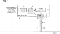
- Fig. 1 shows a configuration example (1) of an onboard lighting system including a wire harness 10 of an embodiment of the invention.
- An onboard lighting system shown in Fig. 1 is a system for controlling an LED unit 31 that is electrical equipment for lighting and is made up of a body side electronic control unit 20, the LED unit 31 and a wire harness 10 that connects them together.
- the LED unit 31 incorporates therein one or more LEDs as a light source and is placed at a predetermined location on a vehicle for use for any one of lighting outside the vehicle, lighting inside the vehicle, lighting for indicators and illumination.
- An actual configuration or specification of the LED unit 31 possibly changes as the grade of the vehicle on which the LED unit 31 is mounted differs or the specification of the vehicle changes.
- the body side EC unit (ECU) 20 is a host control unit in charge of executing a user-oriented control on the vehicle and includes an electrical circuit that is made up mainly of a microcomputer. Thus, the body side EC unit 20 controls the LED unit 31 shown in Fig. 1 and other pieces of electrical equipment. As shown in Fig. 1 , this body side EC unit 20 includes an information acquisition portion 21, a lighting control portion 22, a low speed multiple communication interface (I/F) 23 and a connector 24.
- I/F low speed multiple communication interface
- the information acquisition portion 21 acquires information representing various states of the vehicle that are outputted from predetermined sensors, information representing operated states of various switches and information representing states outside the vehicle that are outputted from predetermined sensors and gives the acquired pieces of information to the lighting control portion 22.
- the lighting control portion 22 sends a control signal for controlling the LED unit 31, which is a control target, to the control target via the low speed multiple communication interface 23 based on states represented by various pieces of information that are inputted from the information acquisition portion 21.
- control signals that the lighting control portion 22 sends to the LED unit 31 include a "command to start emitting red light or lighting a red LED,” a “command to start emitting blue light or lighting a blue LED,” a “command to start emitting red light and blue light or lighting the red LED and the blue LED” and a “command to turn off the LEDs.”
- the types of the control signals that the lighting control portion 22 sends are made common for all grades of a vehicle and all types of light sources.
- the low speed multiple communication interface 23 includes a function necessary to execute a two-way multiple data communication.
- an original standard is adopted that reduces sufficiently a data communication speed when compared with, for example, a controller area network (CAN) that constitutes a communication standard for a vehicle.
- CAN controller area network
- the wire harness 10 shown in Fig. 1 includes an electric wire assembly 11, a connector 12 that is connected to one end side and a connector with controller 13 that is connected to the other end side thereof.
- the connector 12 on the one end side of the wire harness 10 is connected with a connector 24 of the body side EC unit 20, and the connector with controller 13 on the other end side thereof is connected with the LED unit 31 via a sub harness 32.
- the electric wire assembly 11 is made up of three electric wires of a power source wire 11a, an earth wire 11b and a communication wire 11c.
- the connector with controller 13 connected to the other end side of the wire harness 10 means a special connector that incorporates therein an electronic circuit.
- the electronic circuit inside the connector with controller 13 includes a data communication function and a control function that is subordinate to the body side EC unit 20.
- the electronic circuit has the functions necessary to control the LED unit 31.
- the configuration of the electronic circuit of the connector with controller 13 of the wire harness 10 possibly changes as the configuration or specification of the LED unit 31 connected thereto changes.
- the wire harness 10 can be replaced with a wire harness 10 of a different type that corresponds to the change.
- Fig. 2 shows a configuration example of the LED unit 31 included in the onboard lighting system shown in Fig. 1 .
- the LED unit 31 shown in Fig. 2 includes a multiplicity of LED devices 35(1), 35(2), 35(3), 35(4), ... that can be controlled independently.
- the number of LED devices 35 possibly changes as the specification of the LED unit 31 changes.
- the LED devices 35(1), 35(2), 35(3), 35(4), ... shown in Fig. 2 each constitute a light source that incorporates LED elements of three colors of red (R), green (G) and blue (B) and can be controlled in relation to a color of light emitted therefrom.
- the LED unit 31 there may be a case where a light source incorporating LED elements of any two colors of the three colors is used as the LED device 35 or there may be a case where a light source incorporating an LED element of any one of the three colors is used as the LED device 35.
- positive electrode sides of the LED devices 35 are connected to a terminal 36 and negative electrode sides of the LED devices 35 are connected to a terminal group 37.
- the terminal 36 and the terminal group 37 are connected to the connector with controller 13 of the wire harness 10 by way of the connector 32a of the sub harness 32 shown in Fig. 1 .
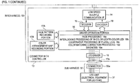
- the electronic circuit provided in the interior of the connector with controller 13 includes a low speed multiple communication interface 14, a decoder 15, a driver operation portion 16, a fade pattern recording portion 17A, a color arrangement map recording portion 17B, an encoder 18 and an LED driver 19.
- the low speed multiple communication interface 14 includes a function necessary to execute a two-way multiple data communication. Additionally, similar to the low speed multiple communication interface 23, the low speed multiple communication interface 14 adopts an original standard and executes a data communication at a lower speed than the speed at which a data communication is executed using the CAN standard.
- the decoder 15 converts serial data that the low speed multiple communication interface 14 receives into parallel data that the driver operation portion 16 can process.
- the encoder 18 converts the parallel data that the driver operation portion 16 sends into serial data that the low speed multiple communication interface 14 can send.
- the driver operation portion 16 is made up of a microcomputer and realizes various types of processing by executing a program incorporated in an interior thereof. Namely, the driver operation portion 16 shown in Fig. 1 includes functions of fade processing 16a, interlocking processing of Bi-Color LED, Tri-color LED 16b, cooperative processing of plural LEDs 16c, color matching correction processing 16d and diagnosis 16e.
- the fade processing 16a determines on the brightness of a light source or a color changing speed.
- the interlocking processing of Bi-Color LED, Tri-color LED 16b controls a timing at which these LEDs operate in an interlocked fashion or a change in color or brightness that is realized by the interlocked operation of the LEDs.
- the cooperative processing of plural LEDs 16c controls an order in which the LEDs of the LED unit 31 are switched on or off or a speed at which the LED devices are switched on or off.
- the color matching correction processing 16d executes an automatic correction to obtain, for example, a specific color developing characteristic of each of the LED devices of the LED unit 31 or a desired lighting color in consideration of a driving environment.
- the diagnosis 16e diagnoses whether or not the electronic circuit in the connector with controller 13 or the LED unit 31 connected thereto operates properly.
- the results of the diagnosis are sent to the body side EC unit 20 via the encoder 18 and the low speed multiple communication interface 14.
- the fade pattern recording portion 17A is a non-volatile memory and records therein a control procedure for use in switching on or off the LED unit 31.
- the fade pattern recording portion 17A records therein, for example, an order in which the cooperative processing of plural LEDs 16c switches on or off the plurality of LED devices of the LED unit 31 or data representing a color arrangement or luminance brightness of the LED unit 31 that the fade processing 16a changes as a control procedure.
- the color arrangement map recording portion 17B is a non-volatile memory and records therein data on combinations of duty ratios necessary to obtain desired color arrangements when controlling energization duties of LEDs of a plurality of colors at the same time.
- the driver operation portion 16 acquires necessary data from the fade pattern recording portion 17A and the color arrangement map recording portion 17B to thereby generate a signal necessary to make the LED unit 31 operate in a desired pattern that is determined in advance.
- the LED driver 19 incorporates a multiplicity of switching elements (transistors or the like) for switching on or off the energization of the individual LED elements or the smallest control units of the LED unit 31 to which the LED driver 19 is connected.
- the driver operation portion 16 outputs a pulse signal for switching on or off the switching elements individually.
- an average value of an electric current that flows to the LED elements can be controlled by repeating switching on and off of the individual switching elements in the LED driver 19 by the use of a pulse signal that appears repeatedly in a constant cycle.
- a pulse signal that appears repeatedly in a constant cycle.
- lighting colors of various hues can be obtained by a combination of a duty ratio at which the R color is switched on and off, a duty ratio at which the G color is switched on and off and a duty ratio at which the B color is switched on and off.
- the luminance brightness of light can be changed by controlling an overall duty ratio f the R, G and B colors.
- the internal configuration of the LED unit 31 changes as a model line, grade and specification of a vehicle differ and change.
- the LED devices 35 each include the LED elements of the three colors.
- the LED device 35 is changed to be made up of LED elements of any two colors of the three colors or to be made up of an LED element of any one of the three colors .
- the number of LED devices 35 that are incorporated in the LED unit 31 is changed as required.
- the specification of each LED device 35 in terms of electric current characteristic or color developing characteristic is changed.
- an appropriate control to match the configuration of the LED unit 31 can be enabled by changing the number of switching elements incorporated in the LED driver 19 of the connector with controller 13, and further by rewriting the contents of the data recorded in the fade pattern recording portion 17A and the color arrangement map recording portion 17B.
- the operational specification of the body side EC unit 20 is fixed or is made common and hence does not have to be changed.
- a difference in model line, a difference in grade or a change in specification of a vehicle can be dealt with only by changing the configuration and operation of the electronic circuit that is incorporated in the connector with controller 13. Consequently, onboard lighting systems of various specifications can be configured, for example, only by replacing a wire harness 10 and an LED unit 31 of one type that are mounted on one vehicle with a wire harness 10 and an LED unit 31 of another type that are mounted on another vehicle.
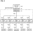
- Fig. 3 shows a configuration example (2) of an onboard lighting system including a vehicle wire harness of a second embodiment of the invention.
- An onboard lighting system shown in Fig. 3 is a modified example made to the onboard lighting system shown in Fig. 1 .
- like reference numerals will be given to like elements to those shown in Fig. 1 .
- LED units 31(1), 31(2), 31(3), 31(4) and 31(5) are connected individually to a body side EC unit 20 by a wire harness 10B.
- a connector 12 is connected to one end side of an electric wire assembly 11B and the other end side of the electric wire assembly 11B is divided into five lines, and connectors with controller 13(1), 13(2), 13(3), 13(4) and 13 (5) are connected individually to end portions of the divided lines of the electric wire assembly 11B.
- the connector 12 at one end side of the wire harness 10B is connected to a connector 24 of the body side EC unit 20. Additionally, the five connectors with controller 13(1), 13(2), 13(3), 13(4) and 13(5) are connected individually to the LED units 31(1), 31(2), 31(3), 31(4) and 31(5) via sub harnesses 32(1), 32(2), 32(3), 32(4) and 32(5), respectively.
- respective configurations of the LED units 31(1), 31(2), 31(3), 31(4) and 31(5) change as a model line, grade and specification of a vehicle differ and change.
- Respective configurations of electronic circuits incorporated in the five connectors with controller 13(1), 13(2), 13(3), 13(4) and 13(5) are similar to those shown in Fig. 1 .
- internal configurations of LED drivers 19 and contents of data recorded in face pattern recording portions 17A and color arrangement map recording portions 17B are changed as required to match the configurations and specifications of the corresponding LED units 31(1) to 31(5).
- the number of connectors with controller 13(1) to 13(5) that are connected to the electric wire assembly 11B can be increased as required. Namely, a multiple data communication is executed at low speeds between the body side EC unit 20 and the electronic circuits in the connectors with controller 13, and therefore, a limitation imposed on the number of channels of a signal carried by a single communication wire 11c is mitigated, thereby making it possible to connect the multiplicity of connectors with controller 13 to the common electric wire assembly 11B. This can also increase the number of LED units 31 that can be connected to a single onboard lighting system.
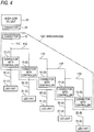
- Fig. 4 shows a configuration example (3) of an onboard lighting system including a vehicle wire harness of a third embodiment of the invention.
- An onboard lighting system shown in Fig. 4 is a modified example made to the onboard lighting system shown in Fig. 1 .
- like reference numerals will be given to like elements to those shown in Fig. 1 .
- LED units 31(1), 31(2), 31(3), 31(4) and 31(5) are connected individually to a body side EC unit 20 by a wire harness 10C.
- a connector 12 is connected to one end side of an electric wire assembly 11C, and a connector with controller 13(1) is connected to the other end of the electric wire assembly 11C.
- one end side of an electric wire assembly 11D is connected to a branch point situated in a halfway position of the electric wire assembly 11C, and a connector with controller 13(2) is connected to the other end side of the electric wire assembly 11D.
- One end side of an electric wire assembly 11E is connected to a branch point situated in a halfway position of the electric wire assembly 11D, and a connector with controller 13(3) is connected to the other end side of the electric wire assembly 11E.
- one end side of an electric wire assembly 11F is connected to a branch point situated in a halfway position of the electric wire assembly 11E, and a connector with controller 13(4) is connected to the other end side of the electric wire assembly 11F.
- one end side of an electric wire assembly 11G is connected to a branch point situated in a halfway position of the electric wire assembly 11F, and a connector with controller 13 (5) is connected to the other end of the electric wire assembly 11G.
- the connector 12 at one end side of the wire harness 10C is connected to a connector 24 of the body side EC unit 20.
- the five connectors with controller 13(1), 13(2), 13(3), 13(4) and 13(5) are connected individually to the LED units 31(1), 31(2), 31(3), 31(4) and 31(5) via sub harnesses 32(1), 32(2), 32(3), 32(4) and 32(5), respectively.
- respective configurations of the LED units 31(1), 31(2), 31(3), 31(4) and 31(5) change as a model line, grade and specification of a vehicle differ and change.
- Respective configurations of electronic circuits incorporated in the five connectors with controller 13(1), 13(2), 13(3), 13(4) and 13(5) are similar to those showing Fig. 1 .
- internal configurations of LED drivers 19 and contents of data recorded in fade pattern recording portions 17A and color arrangement map recording portions 17B are changed as required to match the configurations and specifications of the corresponding LED units 31(1) to 31(5).
- the number of connectors with controller 13(1) to 13(5) that are connected to the electric wire assemblies 11C to 11G can be increased as required. Namely, a multiple data communication is executed at low speeds between the body side EC unit 20 and the electronic circuits in the connectors with controller 13, and therefore, a limitation imposed on the number of channels of a signal carried by a single communication wire 11c is mitigated, thereby making it possible to connect the multiplicity of connectors with controller 13 to the common electric wire assembly 11C. This can also increase the number of LED units 31 that can be connected to a single onboard lighting system.
- an electric wire assembly 11G is retrofitted to a desired branch point situated in a desired position on the electric wire assembly 11F, thereby making it possible to increase the number of connectors with controller 13 and the number of LED units 31 to be connected thereto.
- the vehicle wire in configuring an onboard system for controlling electrical equipment including a light source, can be provided advantageously which is useful in making the operation of the control unit common for various types of electrical equipment.
- the invention providing the advantage is useful when applied to a vehicle wire harness that is electrically connected to a control unit mounted on a vehicle at one end and is electrically connected to one or more light sources at the other end thereof.
Landscapes
- Engineering & Computer Science (AREA)
- Mechanical Engineering (AREA)
- Lighting Device Outwards From Vehicle And Optical Signal (AREA)
- Circuit Arrangement For Electric Light Sources In General (AREA)
- Insulated Conductors (AREA)
Abstract

Description
- The present invention relates to a vehicle wire harness to be electrically connected to a control unit mounded on a vehicle at one end and to be electrically connected to one or more light sources at the other end thereof.
- Conventionally, various pieces of electrical equipment for lighting are mounted on a vehicle such as a motor vehicle. For example, lamps such as a headlamp, a position lamp, a stop lamp, a tail lamp, a turn signal lamp and the like are mounted on the vehicle as electrical equipment for illuminating the outside of the vehicle when the vehicle travels. In addition, various lamps such as a room lamp, an illumination lamp for illuminating various pieces of onboard equipment such as an instrument panel or the like, a decorative illumination lamp, an indicating illumination lamp and the like are also installed in a passenger compartment of the vehicle.
- In general, various pieces of electrical equipment like those described above are individually connected to a predetermined electronic control unit (ECU) by way of wire harnesses that are disposed so as to pass through relevant portions on a vehicle. Then, when the electronic control unit detects an operation of a predetermined switch by the driver or when a predetermined sensor detects a specific situation, the relevant electric equipment for lighting is switched on or off.
- For example, a system for controlling headlamps of a vehicle is disclosed in
Patent Document 1. In the system disclosed inPatent Document 1, a control unit that incorporates therein a microcontroller is described as switching on or off external lamps or generating various beam patterns by controlling luminance brightness, aiming, focus and the like of the external lamps based on various pieces of information acquired from various types of sensors. - In an onboard LED lighting system disclosed in
Patent Document 2, a plurality of LED lamps that are disposed at various locations within a passenger compartment are connected individually to a plurality of slave electronic control units, and the plurality of slave control units are connected to a common master electronic control unit by way of corresponding wire harnesses. In addition, a jumper switch is provided in connectors of the wire harnesses. - In a vehicle lighting system disclosed in
Patent Document 3, a control device (a microcomputer) and an emission light color control device are provided to control light sources (R, G and B LEDs) that are incorporated in a side rearview mirror. An illuminance sensor is connected to the control device, and a hazard switch and a turn signal switch are connected to the emission light color control device. -
- Patent Document 1:
JP-A-2007-45407 - Patent Document 2:
JP-A-2007-276671 - Patent Document 3:
JP-A-2015-71386 - Incidentally, in recent years, electrical equipment for lighting mounted on a vehicle is diversified widely. In addition to the type of such electrical lighting equipment itself, the form of lighting control also tends to be modified variously to match, for example, model types or grades of vehicles.
- Specific examples of lighting controls will be described below.
- (1) In the case of a vehicle of an entry grade, in many cases, lighting is switched on or off through a simple switching operation.
- (2) In the case of a vehicle of a middle grade, a control pattern is often adopted in which light sources are sequentially switched on or off, starting with one in a central position.
- (3) In the case of a vehicle of a high grade, for example, as in
Patent Document 3, in many cases, exclusive electronic control units (ECUs) are connected individually to corresponding pieces of electrical equipment, so that specific lighting controls are performed individually on the pieces of electrical equipment. - However, the simple control described under (1) above cannot produce lighting of a high grade. In addition, when the control described under (2) above is attempted to be executed using a system adopting a standard communication line such as a controller area network (CAN), since the number of channels in a data communication is limited, even in the case where electrical equipment includes a number of light sources, the light sources cannot be controlled independently by making use of many channels. When the system described under (3) above is adopted, since exclusive electronic control units (ECUs) have to be developed for vehicles or pieces of electrical equipment, it is not possible to suppress an increase in development cost or parts cost.
- In particular, in recent years, as disclosed in
Patent Document 2 andPatent Document 3, in many cases, light emitting diodes (LEDs) are adopted as light sources for various types of lighting. Further, there is a tendency in which the number of LED elements that make up one piece of electrical equipment (a lamp) changes or increases greatly as the grade of a vehicle gets higher. In addition, in the case of electrical equipment that adopts a bi-color or tri-color LED device, the color of light emitted from the LED device needs to be controlled as required. Thus, in relation to an electronic control unit (ECU) for use in controlling electrical lighting equipment like this electrical equipment described above, the configuration of an output circuit (a driver) needs to be optimized or exclusive software needs to developed in accordance with a type of electrical equipment that makes up a light source. Further, the electrical equipment needs to be controlled so as to produce a feeling of high grade or obtain illumination light of high quality by making full use of the characteristics of the electrical equipment. - The invention has been made in view of the situations described above, and an object thereof is to provide a vehicle wire harness that is useful in making operations of a control unit common for various types of pieces of electrical equipment in configuring an onboard system for controlling a piece of electrical equipment including a light source.
- In order to achieve the object described above, a vehicle wire harness according to the invention has aspects described under (1) to (4) below.
- (1) A vehicle wire harness that is connected electrically to a control unit mounted on a vehicle at one end and is connected electrically to one or more light sources at the other end thereof, the vehicle wire harness having:
- a driver operation portion configured to receive a control signal designating a lighting form for the one or more light sources from the control unit and output a drive pattern for driving the one or more light sources, wherein
- the driver operation portion is subordinate to the control unit.
When an onboard lighting system is configured using the vehicle wire harness according to (1) above, the relation between the control signal that the control unit outputs and the one or more light sources that are connected to a downstream side of the vehicle wire harness can be matched by the driver operation portion in the interior of the vehicle wire harness. Consequently, even in the case where the configurations or specifications of the light sources connected change as the grade of a vehicle changes, the change can be dealt with at the driver operation portion. This enables the operations of the host control unit to be made common for various different types of pieces of electrical equipment (light sources) or various different grades of a vehicle. Namely, the necessity of changing the configuration or the contents of processing of the control unit can be obviated, leading to a reduction in development cost of the whole system or parts cost. - (2) The vehicle wire harness according to (1) above, wherein the control unit makes up an electrical circuit that is mounted on the vehicle, and wherein the one end can detachably be attached to a connector of the electrical circuit.
The vehicle wire harness according to (2) above can detachably be attached to the control unit by the connector at the one end thereof, and therefore, for example, a plurality of vehicle wire harnesses of different types can easily be replaced. Thus, a change in type of electrical equipment (a light source) to be connected or a change in grade of a vehicle can be dealt with only by replacing one vehicle wire harness with another vehicle wire harness. - (3) The vehicle wire harness according to (1) or (2) above, including a storage portion configured to store a controlling procedure corresponding to the lighting form, wherein the driver operation portion reads out from the storage portion the controlling procedure corresponding to the lighting form that the driver operation portion has received to generate a drive pattern in accordance with the controlling procedure.
According to the vehicle wire harness configured as described under (3) above, the drive pattern that the driver operation portion generates can be changed only by changing the data of the controlling procedure held in the storage portion. Thus, a change in type of electrical equipment (a light source) to be connected to the downstream side of the vehicle wire harness or a change in grade of a vehicle can easily be dealt with. - (4) The vehicle wire harness according to (3) above, wherein the controlling procedure is a procedure of controlling at least one of a lighting order, color arrangement and luminance brightness of the one or more light sources.
- According to the vehicle wire harness configured as described under (4) above, at least one of the lighting order, color arrangement and luminance brightness of the one or more light sources can be changed only by changing the controlling procedure. Thus, a change in type of electrical equipment (a light source) to be connected to the downstream side of the vehicle wire harness or a change in grade of a vehicle can easily be dealt with.
- When configuring an onboard system for controlling electrical equipment including a light source, the vehicle wire harness of the invention is useful in making operations of a control unit common for various types of pieces of electrical equipment. Namely, the relation between the control unit that the control unit outputs and the light source connected to the downstream side of the vehicle wire harness can matched by the driver operation portion in the interior of the vehicle wire harness. Thus, even though the configuration or specification of the light source to be connected changes as the grade of the vehicle changes, the change can be dealt with by the driver operation portion. This enables the operation of the host control unit to be made common for various different types of pieces of electrical equipment (light sources) or various different grades of a vehicle. Namely, the necessity of changing the configuration or the contents of processing of the control unit can be obviated, leading to a reduction in development cost of the whole system or parts cost.
- The invention has briefly been described heretofore. Further, the details of the invention will be made clearer by perusing a mode for carrying out the invention (hereinafter, referred to as "embodiments") that will be described below by reference to accompanying drawings.
-
- [
Fig. 1] Fig. 1 is a block diagram showing a configuration example (1) of an onboard lighting system including a vehicle wire harness of an embodiment of the invention. - [
Fig. 2] Fig. 2 is an electrical circuit diagram showing a configuration example of an LED unit that is included in the onboard lighting system shown inFig. 1 . - [
Fig. 3] Fig. 3 is a block diagram showing a configuration example (2) of an onboard lighting system including a vehicle wire harness of another embodiment of the invention. - [
Fig. 4] Fig. 4 is a block diagram showing a configuration example (3) of an onboard lighting system including a vehicle wire harness of a further embodiment of the invention. - Specific embodiments relating to the invention will be described below by reference to the drawings.
- Specific embodiments relating to vehicle wire harnesses of the invention will described below by reference to the drawings.
-
Fig. 1 shows a configuration example (1) of an onboard lighting system including awire harness 10 of an embodiment of the invention. - An onboard lighting system shown in
Fig. 1 is a system for controlling anLED unit 31 that is electrical equipment for lighting and is made up of a body sideelectronic control unit 20, theLED unit 31 and awire harness 10 that connects them together. - The
LED unit 31 incorporates therein one or more LEDs as a light source and is placed at a predetermined location on a vehicle for use for any one of lighting outside the vehicle, lighting inside the vehicle, lighting for indicators and illumination. An actual configuration or specification of theLED unit 31 possibly changes as the grade of the vehicle on which theLED unit 31 is mounted differs or the specification of the vehicle changes. - The body side EC unit (ECU) 20 is a host control unit in charge of executing a user-oriented control on the vehicle and includes an electrical circuit that is made up mainly of a microcomputer. Thus, the body
side EC unit 20 controls theLED unit 31 shown inFig. 1 and other pieces of electrical equipment. As shown inFig. 1 , this bodyside EC unit 20 includes aninformation acquisition portion 21, alighting control portion 22, a low speed multiple communication interface (I/F) 23 and aconnector 24. - The
information acquisition portion 21 acquires information representing various states of the vehicle that are outputted from predetermined sensors, information representing operated states of various switches and information representing states outside the vehicle that are outputted from predetermined sensors and gives the acquired pieces of information to thelighting control portion 22. - The
lighting control portion 22 sends a control signal for controlling theLED unit 31, which is a control target, to the control target via the low speedmultiple communication interface 23 based on states represented by various pieces of information that are inputted from theinformation acquisition portion 21. - Specific examples of control signals that the
lighting control portion 22 sends to theLED unit 31 include a "command to start emitting red light or lighting a red LED," a "command to start emitting blue light or lighting a blue LED," a "command to start emitting red light and blue light or lighting the red LED and the blue LED" and a "command to turn off the LEDs." In this embodiment, the types of the control signals that thelighting control portion 22 sends are made common for all grades of a vehicle and all types of light sources. - Consequently, even though, for example, the type or configuration of the
LED unit 31 that is connected to a downstream side of thewire harness 10 changes, the configuration or operation of the bodyside EC unit 20 does not have to be changed. - The low speed
multiple communication interface 23 includes a function necessary to execute a two-way multiple data communication. However, an original standard is adopted that reduces sufficiently a data communication speed when compared with, for example, a controller area network (CAN) that constitutes a communication standard for a vehicle. - The following advantages can be obtained by reducing the communication speed.
- (1) The low data communication speed makes it difficult for the low speed
multiple communication interface 23 to be affected by noise in a transmission line. - (2) The limitation on the number of communication channels that can be transmitted in one transmission line is mitigated, thereby making it possible to increase the number of pieces of electric equipment that can be connected thereto.
- The
wire harness 10 shown inFig. 1 includes anelectric wire assembly 11, aconnector 12 that is connected to one end side and a connector withcontroller 13 that is connected to the other end side thereof. Theconnector 12 on the one end side of thewire harness 10 is connected with aconnector 24 of the bodyside EC unit 20, and the connector withcontroller 13 on the other end side thereof is connected with theLED unit 31 via asub harness 32. - In the example shown in
Fig. 1 , theelectric wire assembly 11 is made up of three electric wires of apower source wire 11a, anearth wire 11b and acommunication wire 11c. - The connector with
controller 13 connected to the other end side of thewire harness 10 means a special connector that incorporates therein an electronic circuit. Although the details of the connector withcontroller 13 will be described later, the electronic circuit inside the connector withcontroller 13 includes a data communication function and a control function that is subordinate to the bodyside EC unit 20. Thus, the electronic circuit has the functions necessary to control theLED unit 31. - In this embodiment, the configuration of the electronic circuit of the connector with
controller 13 of thewire harness 10 possibly changes as the configuration or specification of theLED unit 31 connected thereto changes. For example, in the case where theLED unit 31 changes as the model line or grade of the vehicle changes, thewire harness 10 can be replaced with awire harness 10 of a different type that corresponds to the change. -
Fig. 2 shows a configuration example of theLED unit 31 included in the onboard lighting system shown inFig. 1 . - The
LED unit 31 shown inFig. 2 includes a multiplicity of LED devices 35(1), 35(2), 35(3), 35(4), ... that can be controlled independently. The number ofLED devices 35 possibly changes as the specification of theLED unit 31 changes. - In addition, the LED devices 35(1), 35(2), 35(3), 35(4), ... shown in
Fig. 2 each constitute a light source that incorporates LED elements of three colors of red (R), green (G) and blue (B) and can be controlled in relation to a color of light emitted therefrom. - Depending on the specification of the
LED unit 31, there may be a case where a light source incorporating LED elements of any two colors of the three colors is used as theLED device 35 or there may be a case where a light source incorporating an LED element of any one of the three colors is used as theLED device 35. - In the
LED unit 31 shown inFig. 2 , positive electrode sides of theLED devices 35 are connected to a terminal 36 and negative electrode sides of theLED devices 35 are connected to aterminal group 37. The terminal 36 and theterminal group 37 are connected to the connector withcontroller 13 of thewire harness 10 by way of theconnector 32a of thesub harness 32 shown inFig. 1 . - As shown in
Fig. 1 , the electronic circuit provided in the interior of the connector withcontroller 13 includes a low speedmultiple communication interface 14, adecoder 15, adriver operation portion 16, a fadepattern recording portion 17A, a color arrangementmap recording portion 17B, anencoder 18 and anLED driver 19. - The low speed
multiple communication interface 14 includes a function necessary to execute a two-way multiple data communication. Additionally, similar to the low speedmultiple communication interface 23, the low speedmultiple communication interface 14 adopts an original standard and executes a data communication at a lower speed than the speed at which a data communication is executed using the CAN standard. - The
decoder 15 converts serial data that the low speedmultiple communication interface 14 receives into parallel data that thedriver operation portion 16 can process. Theencoder 18 converts the parallel data that thedriver operation portion 16 sends into serial data that the low speedmultiple communication interface 14 can send. - The
driver operation portion 16 is made up of a microcomputer and realizes various types of processing by executing a program incorporated in an interior thereof. Namely, thedriver operation portion 16 shown inFig. 1 includes functions offade processing 16a, interlocking processing of Bi-Color LED,Tri-color LED 16b, cooperative processing ofplural LEDs 16c, color matchingcorrection processing 16d anddiagnosis 16e. - In a state transition occurring when the
LED unit 31 is switched on or off in accordance with an instruction from the bodyside EC unit 20, thefade processing 16a determines on the brightness of a light source or a color changing speed. - In the case where the LED devices of the
LED unit 31 each include both a Bi-Color LED and a Tri-Color LED, the interlocking processing of Bi-Color LED,Tri-color LED 16b controls a timing at which these LEDs operate in an interlocked fashion or a change in color or brightness that is realized by the interlocked operation of the LEDs. - In the case where the
LED unit 31 includes a plurality of LED devices, when theLED unit 31 is switched on or off, the cooperative processing ofplural LEDs 16c controls an order in which the LEDs of theLED unit 31 are switched on or off or a speed at which the LED devices are switched on or off. - The color
matching correction processing 16d executes an automatic correction to obtain, for example, a specific color developing characteristic of each of the LED devices of theLED unit 31 or a desired lighting color in consideration of a driving environment. - The
diagnosis 16e diagnoses whether or not the electronic circuit in the connector withcontroller 13 or theLED unit 31 connected thereto operates properly. The results of the diagnosis are sent to the bodyside EC unit 20 via theencoder 18 and the low speedmultiple communication interface 14. - The fade
pattern recording portion 17A is a non-volatile memory and records therein a control procedure for use in switching on or off theLED unit 31. The fadepattern recording portion 17A records therein, for example, an order in which the cooperative processing ofplural LEDs 16c switches on or off the plurality of LED devices of theLED unit 31 or data representing a color arrangement or luminance brightness of theLED unit 31 that thefade processing 16a changes as a control procedure. - The color arrangement
map recording portion 17B is a non-volatile memory and records therein data on combinations of duty ratios necessary to obtain desired color arrangements when controlling energization duties of LEDs of a plurality of colors at the same time. - The
driver operation portion 16 acquires necessary data from the fadepattern recording portion 17A and the color arrangementmap recording portion 17B to thereby generate a signal necessary to make theLED unit 31 operate in a desired pattern that is determined in advance. - The
LED driver 19 incorporates a multiplicity of switching elements (transistors or the like) for switching on or off the energization of the individual LED elements or the smallest control units of theLED unit 31 to which theLED driver 19 is connected. Thedriver operation portion 16 outputs a pulse signal for switching on or off the switching elements individually. - For example, an average value of an electric current that flows to the LED elements can be controlled by repeating switching on and off of the individual switching elements in the
LED driver 19 by the use of a pulse signal that appears repeatedly in a constant cycle. For example, when the energization of three R (red), G (green) and B (blue) LED elements is controlled individually by theLED driver 19, lighting colors of various hues can be obtained by a combination of a duty ratio at which the R color is switched on and off, a duty ratio at which the G color is switched on and off and a duty ratio at which the B color is switched on and off. Additionally, the luminance brightness of light can be changed by controlling an overall duty ratio f the R, G and B colors. - For example, the internal configuration of the
LED unit 31 changes as a model line, grade and specification of a vehicle differ and change. For example, in the example shown inFig. 2 , theLED devices 35 each include the LED elements of the three colors. However, there is the possibility that theLED device 35 is changed to be made up of LED elements of any two colors of the three colors or to be made up of an LED element of any one of the three colors . In addition, the number ofLED devices 35 that are incorporated in theLED unit 31 is changed as required. There is also the possibility that the specification of eachLED device 35 in terms of electric current characteristic or color developing characteristic is changed. - In the case where the number of terminals of the
terminal group 37 changes as the number ofLED devices 35 changes or the type of theLED device 35 changes, an appropriate control to match the configuration of theLED unit 31 can be enabled by changing the number of switching elements incorporated in theLED driver 19 of the connector withcontroller 13, and further by rewriting the contents of the data recorded in the fadepattern recording portion 17A and the color arrangementmap recording portion 17B. - Namely, the operational specification of the body
side EC unit 20 is fixed or is made common and hence does not have to be changed. Thus, a difference in model line, a difference in grade or a change in specification of a vehicle can be dealt with only by changing the configuration and operation of the electronic circuit that is incorporated in the connector withcontroller 13. Consequently, onboard lighting systems of various specifications can be configured, for example, only by replacing awire harness 10 and anLED unit 31 of one type that are mounted on one vehicle with awire harness 10 and anLED unit 31 of another type that are mounted on another vehicle. -
Fig. 3 shows a configuration example (2) of an onboard lighting system including a vehicle wire harness of a second embodiment of the invention. An onboard lighting system shown inFig. 3 is a modified example made to the onboard lighting system shown inFig. 1 . Thus, inFig. 3 , like reference numerals will be given to like elements to those shown inFig. 1 . - In the onboard lighting system shown in
Fig. 3 , five LED units 31(1), 31(2), 31(3), 31(4) and 31(5) are connected individually to a bodyside EC unit 20 by awire harness 10B. - In the
wire harness 10B, aconnector 12 is connected to one end side of anelectric wire assembly 11B and the other end side of theelectric wire assembly 11B is divided into five lines, and connectors with controller 13(1), 13(2), 13(3), 13(4) and 13 (5) are connected individually to end portions of the divided lines of theelectric wire assembly 11B. - The
connector 12 at one end side of thewire harness 10B is connected to aconnector 24 of the bodyside EC unit 20. Additionally, the five connectors with controller 13(1), 13(2), 13(3), 13(4) and 13(5) are connected individually to the LED units 31(1), 31(2), 31(3), 31(4) and 31(5) via sub harnesses 32(1), 32(2), 32(3), 32(4) and 32(5), respectively. - Here, respective configurations of the LED units 31(1), 31(2), 31(3), 31(4) and 31(5) change as a model line, grade and specification of a vehicle differ and change. Respective configurations of electronic circuits incorporated in the five connectors with controller 13(1), 13(2), 13(3), 13(4) and 13(5) are similar to those shown in
Fig. 1 . However, internal configurations ofLED drivers 19 and contents of data recorded in facepattern recording portions 17A and color arrangementmap recording portions 17B are changed as required to match the configurations and specifications of the corresponding LED units 31(1) to 31(5). - The number of connectors with controller 13(1) to 13(5) that are connected to the
electric wire assembly 11B can be increased as required. Namely, a multiple data communication is executed at low speeds between the bodyside EC unit 20 and the electronic circuits in the connectors withcontroller 13, and therefore, a limitation imposed on the number of channels of a signal carried by asingle communication wire 11c is mitigated, thereby making it possible to connect the multiplicity of connectors withcontroller 13 to the commonelectric wire assembly 11B. This can also increase the number ofLED units 31 that can be connected to a single onboard lighting system. -
Fig. 4 shows a configuration example (3) of an onboard lighting system including a vehicle wire harness of a third embodiment of the invention. An onboard lighting system shown inFig. 4 is a modified example made to the onboard lighting system shown inFig. 1 . Thus, inFig. 4 , like reference numerals will be given to like elements to those shown inFig. 1 . - In the onboard lighting system shown in
Fig. 4 , five LED units 31(1), 31(2), 31(3), 31(4) and 31(5) are connected individually to a bodyside EC unit 20 by awire harness 10C. - In the
wire harness 10C, aconnector 12 is connected to one end side of anelectric wire assembly 11C, and a connector with controller 13(1) is connected to the other end of theelectric wire assembly 11C. Then, one end side of anelectric wire assembly 11D is connected to a branch point situated in a halfway position of theelectric wire assembly 11C, and a connector with controller 13(2) is connected to the other end side of theelectric wire assembly 11D. One end side of anelectric wire assembly 11E is connected to a branch point situated in a halfway position of theelectric wire assembly 11D, and a connector with controller 13(3) is connected to the other end side of theelectric wire assembly 11E. Further, one end side of anelectric wire assembly 11F is connected to a branch point situated in a halfway position of theelectric wire assembly 11E, and a connector with controller 13(4) is connected to the other end side of theelectric wire assembly 11F. Additionally, one end side of anelectric wire assembly 11G is connected to a branch point situated in a halfway position of theelectric wire assembly 11F, and a connector with controller 13 (5) is connected to the other end of theelectric wire assembly 11G. - The
connector 12 at one end side of thewire harness 10C is connected to aconnector 24 of the bodyside EC unit 20. The five connectors with controller 13(1), 13(2), 13(3), 13(4) and 13(5) are connected individually to the LED units 31(1), 31(2), 31(3), 31(4) and 31(5) via sub harnesses 32(1), 32(2), 32(3), 32(4) and 32(5), respectively. - Here, respective configurations of the LED units 31(1), 31(2), 31(3), 31(4) and 31(5) change as a model line, grade and specification of a vehicle differ and change. Respective configurations of electronic circuits incorporated in the five connectors with controller 13(1), 13(2), 13(3), 13(4) and 13(5) are similar to those showing
Fig. 1 . However, internal configurations ofLED drivers 19 and contents of data recorded in fadepattern recording portions 17A and color arrangementmap recording portions 17B are changed as required to match the configurations and specifications of the corresponding LED units 31(1) to 31(5). - The number of connectors with controller 13(1) to 13(5) that are connected to the
electric wire assemblies 11C to 11G can be increased as required. Namely, a multiple data communication is executed at low speeds between the bodyside EC unit 20 and the electronic circuits in the connectors withcontroller 13, and therefore, a limitation imposed on the number of channels of a signal carried by asingle communication wire 11c is mitigated, thereby making it possible to connect the multiplicity of connectors withcontroller 13 to the commonelectric wire assembly 11C. This can also increase the number ofLED units 31 that can be connected to a single onboard lighting system. - With the
wire harness 11C that does not include, for example, theelectric wire assembly 11G shown inFig. 4 mounted in advance on the vehicle, anelectric wire assembly 11G is retrofitted to a desired branch point situated in a desired position on theelectric wire assembly 11F, thereby making it possible to increase the number of connectors withcontroller 13 and the number ofLED units 31 to be connected thereto. - Here, the characteristics of the embodiments of the vehicle wire harnesses according to the invention described heretofore will be summarized briefly under [1] to [4] below.
- [1] The vehicle wire harness (the
wire harness - the driver operation portion (16) configured to receive the control signal designating the lighting form for the one or more light sources from the control unit and output the drive pattern for driving the one or more light sources, wherein
- the driver operation portion is subordinate to the control unit.
- [2] The vehicle wire harness according to [1] above, wherein the control unit makes up the electrical circuit that is mounted on the vehicle, and wherein the one end (the connector 12) can detachably be attached to the connector (24) of the electrical circuit.
- [3] The vehicle wire harness according to [1] or [2] above, including the storage portion (the fade
pattern recording portion 17A, the color arrangementmap recording portion 17B) configured to store the controlling procedure corresponding to the lighting form, wherein the driver operation portion (16) reads out the controlling procedure corresponding to the lighting form that the driver operation portion has received to generate the drive pattern in accordance with the controlling procedure. - [4] The vehicle wire harness according to [3] above, wherein the controlling procedure is a procedure of controlling at least one of a lighting order, color arrangement and luminance brightness of the one or more light sources.
- While the invention has been described in detail or by reference to the specific embodiments, it is obvious to those skilled in the art to which the invention pertains that various alterations or modifications can be made thereto without departing from the spirit and scope of the invention.
- This patent application is based on Japanese Patent Application (No.
2015-191705 - According to the invention, in configuring an onboard system for controlling electrical equipment including a light source, the vehicle wire can be provided advantageously which is useful in making the operation of the control unit common for various types of electrical equipment. The invention providing the advantage is useful when applied to a vehicle wire harness that is electrically connected to a control unit mounted on a vehicle at one end and is electrically connected to one or more light sources at the other end thereof.
-
- 10, 10B, 10C Wire harness
- 11, 11B, 11C, 11D, 11E, 11F, 11G Electric wire assembly
- 11a Electric wire
- 11b Earth wire
- 11c Communication wire
- 12, 24, 32a Connector
- 13 Connector with controller
- 13a Terminal portion
- 14, 23 Low speed multiple communication interface
- 15 Decoder
- 16 Driver operation portion
- 16a Fade processing
- 16b Interlocking processing of Bi-Color LED Tri-color LED
- 16c Cooperative processing of plural LEDs
- 16d Color matching correction processing
- 16e Diagnosis
- 17A Fade pattern recording portion
- 17B Color arrangement map recording portion
- 18 Encoder
- 19 LED driver
- 20 Body side EC unit
- 21 Information acquisition portion
- 22 Lighting control portion
- 31 LED unit
- 32 Sub harness
- 35 LED device
- 36 Terminal
- 37 Terminal group
Claims (4)
- A vehicle wire harness including one end to be electrically connected to a control unit mounted on a vehicle and the other end to be electrically connected to one or more light sources, the vehicle wire harness comprising:a driver operation portion configured to receive a control signal designating a lighting form for the one or more light sources from the control unit and to output a drive pattern for driving the one or more light sources,wherein the driver operation portion is subordinate to the control unit.
- The vehicle wire harness according to Claim 1, wherein the control unit configures an electrical circuit mounted on the vehicle, and
wherein the one end is to be detachably attached to a connector of the electrical circuit. - The vehicle wire harness according to Claim 1 or 2, further comprising:a storage portion that stores a controlling procedure corresponding to the lighting form,wherein the driver operation portion is configured to read out from the storage portion the controlling procedure corresponding to the lighting form that the driver operation portion received and to generate a drive pattern in accordance with the controlling procedure.
- The vehicle wire harness according to Claim 3, wherein the controlling procedure is a procedure of controlling at least one of a lighting order, color arrangement and luminance brightness of the one or more light sources.
Applications Claiming Priority (2)
| Application Number | Priority Date | Filing Date | Title |
|---|---|---|---|
| JP2015191705A JP6389158B2 (en) | 2015-09-29 | 2015-09-29 | Wire harness for vehicles |
| PCT/JP2016/078877 WO2017057605A1 (en) | 2015-09-29 | 2016-09-29 | Wire harness for vehicle |
Publications (3)
| Publication Number | Publication Date |
|---|---|
| EP3357762A1 true EP3357762A1 (en) | 2018-08-08 |
| EP3357762A4 EP3357762A4 (en) | 2019-04-10 |
| EP3357762B1 EP3357762B1 (en) | 2020-04-29 |
Family
ID=58423786
Family Applications (1)
| Application Number | Title | Priority Date | Filing Date |
|---|---|---|---|
| EP16851776.1A Active EP3357762B1 (en) | 2015-09-29 | 2016-09-29 | Wire harness for vehicle |
Country Status (5)
| Country | Link |
|---|---|
| US (1) | US10576913B2 (en) |
| EP (1) | EP3357762B1 (en) |
| JP (1) | JP6389158B2 (en) |
| CN (1) | CN108136976B (en) |
| WO (1) | WO2017057605A1 (en) |
Families Citing this family (7)
| Publication number | Priority date | Publication date | Assignee | Title |
|---|---|---|---|---|
| EP3562269A1 (en) * | 2018-04-27 | 2019-10-30 | Valeo Iluminacion | Electronic assembly, lighting device and method for manufacturing a lighting device |
| CN112578699A (en) * | 2019-09-27 | 2021-03-30 | 大陆汽车电子(连云港)有限公司 | Interface assembly for coupling a controller and a wiring harness |
| US11153948B2 (en) * | 2020-03-02 | 2021-10-19 | Infineon Technologies Ag | Modular front light LED driver messaging system |
| KR102471925B1 (en) * | 2020-09-11 | 2022-11-29 | 주식회사 스카이오토넷 | Apparatus for indetifying accelerator data |
| JP7261208B6 (en) * | 2020-10-28 | 2023-05-10 | 矢崎総業株式会社 | Connection method and electrical unit |
| WO2022265082A1 (en) * | 2021-06-17 | 2022-12-22 | 株式会社小糸製作所 | Vehicle control system, electrical component, and ecu |
| KR20240159359A (en) * | 2023-04-28 | 2024-11-05 | 현대모비스 주식회사 | LED lamp system |
Family Cites Families (22)
| Publication number | Priority date | Publication date | Assignee | Title |
|---|---|---|---|---|
| US6611610B1 (en) | 1997-04-02 | 2003-08-26 | Gentex Corporation | Vehicle lamp control |
| US6587573B1 (en) | 2000-03-20 | 2003-07-01 | Gentex Corporation | System for controlling exterior vehicle lights |
| US5837994C1 (en) | 1997-04-02 | 2001-10-16 | Gentex Corp | Control system to automatically dim vehicle head lamps |
| JP2001253267A (en) * | 2000-03-10 | 2001-09-18 | Sumitomo Wiring Syst Ltd | Connecting structure for indicator display |
| US20040225811A1 (en) * | 2001-04-04 | 2004-11-11 | Fosler Ross M. | Digital addressable lighting interface bridge |
| JP2006062594A (en) * | 2004-08-30 | 2006-03-09 | Yazaki Corp | Car interior lamp control system |
| DE102006010640A1 (en) * | 2006-03-08 | 2007-09-13 | Robert Bosch Gmbh | Electronic control system, wiring harness and plug |
| JP4487968B2 (en) | 2006-04-07 | 2010-06-23 | 豊田合成株式会社 | In-vehicle LED lighting system |
| US7410269B2 (en) * | 2006-06-06 | 2008-08-12 | S.C. Johnson & Son, Inc. | Decorative light system |
| US8567992B2 (en) * | 2006-09-12 | 2013-10-29 | Huizhou Light Engine Ltd. | Integrally formed light emitting diode light wire and uses thereof |
| DE102007029423B4 (en) * | 2007-06-26 | 2009-09-03 | Sick Ag | control system |
| JP5360967B2 (en) * | 2008-10-08 | 2013-12-04 | 矢崎総業株式会社 | ECU system |
| CN101384119B (en) * | 2008-10-17 | 2012-05-23 | 奇瑞汽车股份有限公司 | Automobile external lamp controller based on CAN and LIN bus |
| US8280040B2 (en) * | 2009-02-04 | 2012-10-02 | Globalfoundries Inc. | Processor instructions for improved AES encryption and decryption |
| DE102010030520A1 (en) * | 2010-06-25 | 2011-12-29 | Jungheinrich Aktiengesellschaft | Work light for a commercial vehicle, in particular industrial truck |
| JP5705528B2 (en) * | 2010-12-21 | 2015-04-22 | 矢崎総業株式会社 | Wire harness structure and lighting unit |
| DK177534B1 (en) * | 2012-03-21 | 2013-09-08 | Martin Professional As | Flexible led pixel string with two shielding ground lines |
| DE102012014724B3 (en) * | 2012-04-14 | 2013-09-12 | Volkswagen Aktiengesellschaft | Apparatus, method and computer program for operating a data bus system of a motor vehicle |
| JP2015071386A (en) | 2013-10-04 | 2015-04-16 | 矢崎総業株式会社 | Vehicle lighting device |
| JP6423154B2 (en) * | 2014-01-17 | 2018-11-14 | 矢崎総業株式会社 | Disconnection detector |
| US10300840B2 (en) * | 2014-02-04 | 2019-05-28 | Koito Manufacturing Co., Ltd. | Vehicle lamp control system |
| JPWO2015163312A1 (en) * | 2014-04-21 | 2017-09-28 | 山口 作太郎 | Wire harness system, apparatus and power supply method |
-
2015
- 2015-09-29 JP JP2015191705A patent/JP6389158B2/en active Active
-
2016
- 2016-09-29 CN CN201680057203.1A patent/CN108136976B/en active Active
- 2016-09-29 EP EP16851776.1A patent/EP3357762B1/en active Active
- 2016-09-29 WO PCT/JP2016/078877 patent/WO2017057605A1/en not_active Ceased
-
2018
- 2018-03-28 US US15/938,554 patent/US10576913B2/en active Active
Also Published As
| Publication number | Publication date |
|---|---|
| US10576913B2 (en) | 2020-03-03 |
| WO2017057605A1 (en) | 2017-04-06 |
| JP6389158B2 (en) | 2018-09-12 |
| US20180215306A1 (en) | 2018-08-02 |
| EP3357762A4 (en) | 2019-04-10 |
| CN108136976A (en) | 2018-06-08 |
| EP3357762B1 (en) | 2020-04-29 |
| JP2017065375A (en) | 2017-04-06 |
| CN108136976B (en) | 2021-10-22 |
Similar Documents
| Publication | Publication Date | Title |
|---|---|---|
| EP3357762B1 (en) | Wire harness for vehicle | |
| KR102370464B1 (en) | Reinforcement of vehicle emergency system | |
| JP5705528B2 (en) | Wire harness structure and lighting unit | |
| US9913342B2 (en) | Illumination control device | |
| ES2219626T3 (en) | LIGHTING LAMP OR SIGNALING FOR VEHICLE AND LIGHTING SYSTEM OR SIGNALING EQUIPPED WITH AT LEAST ONE OF THESE LIGHTS. | |
| US9705597B2 (en) | Modular light bar messaging system | |
| EP2722226B1 (en) | Lighting control system for vehicle lamp | |
| US7425088B2 (en) | Vehicle running light system | |
| CN114435231A (en) | car lamp control system | |
| US20200101893A1 (en) | Individualizable lighting system for a vehicle | |
| CN114670747A (en) | Atmosphere lamp control system and vehicle | |
| CN111148308A (en) | Vehicle-mounted atmosphere lamp control method and system | |
| CN209330438U (en) | A kind of atmosphere lamp system and automobile | |
| JP2006062594A (en) | Car interior lamp control system | |
| US20210394669A1 (en) | Smart rear lighting system | |
| JP6704097B1 (en) | LED lighting module for automobile | |
| JP2014103078A (en) | LED dimming circuit for vehicles | |
| US11130454B2 (en) | On-vehicle controller | |
| JP2024018641A (en) | In-vehicle network system | |
| JP2006062591A (en) | Car exterior lamp control system | |
| JP7798909B2 (en) | Vehicle lighting fixture, vehicle lighting fixture control device and control method, vehicle lighting fixture system, vehicle lighting fixture setting device and setting method | |
| US20250338381A1 (en) | Vehicle interior lighting system | |
| WO2017066677A1 (en) | Lighting system with a node for independently controlling more than one light | |
| JP2024018638A (en) | In-vehicle network system | |
| JP2008273390A (en) | Outside-vehicle LED lamp control device and electrical junction box |
Legal Events
| Date | Code | Title | Description |
|---|---|---|---|
| STAA | Information on the status of an ep patent application or granted ep patent |
Free format text: STATUS: THE INTERNATIONAL PUBLICATION HAS BEEN MADE |
|
| PUAI | Public reference made under article 153(3) epc to a published international application that has entered the european phase |
Free format text: ORIGINAL CODE: 0009012 |
|
| STAA | Information on the status of an ep patent application or granted ep patent |
Free format text: STATUS: REQUEST FOR EXAMINATION WAS MADE |
|
| 17P | Request for examination filed |
Effective date: 20180327 |
|
| AK | Designated contracting states |
Kind code of ref document: A1 Designated state(s): AL AT BE BG CH CY CZ DE DK EE ES FI FR GB GR HR HU IE IS IT LI LT LU LV MC MK MT NL NO PL PT RO RS SE SI SK SM TR |
|
| AX | Request for extension of the european patent |
Extension state: BA ME |
|
| DAV | Request for validation of the european patent (deleted) | ||
| DAX | Request for extension of the european patent (deleted) | ||
| A4 | Supplementary search report drawn up and despatched |
Effective date: 20190307 |
|
| RIC1 | Information provided on ipc code assigned before grant |
Ipc: B60Q 1/00 20060101ALI20190301BHEP Ipc: B60R 16/02 20060101AFI20190301BHEP |
|
| GRAP | Despatch of communication of intention to grant a patent |
Free format text: ORIGINAL CODE: EPIDOSNIGR1 |
|
| STAA | Information on the status of an ep patent application or granted ep patent |
Free format text: STATUS: GRANT OF PATENT IS INTENDED |
|
| INTG | Intention to grant announced |
Effective date: 20200110 |
|
| GRAS | Grant fee paid |
Free format text: ORIGINAL CODE: EPIDOSNIGR3 |
|
| GRAA | (expected) grant |
Free format text: ORIGINAL CODE: 0009210 |
|
| STAA | Information on the status of an ep patent application or granted ep patent |
Free format text: STATUS: THE PATENT HAS BEEN GRANTED |
|
| AK | Designated contracting states |
Kind code of ref document: B1 Designated state(s): AL AT BE BG CH CY CZ DE DK EE ES FI FR GB GR HR HU IE IS IT LI LT LU LV MC MK MT NL NO PL PT RO RS SE SI SK SM TR |
|
| REG | Reference to a national code |
Ref country code: GB Ref legal event code: FG4D |
|
| REG | Reference to a national code |
Ref country code: CH Ref legal event code: EP |
|
| REG | Reference to a national code |
Ref country code: AT Ref legal event code: REF Ref document number: 1262835 Country of ref document: AT Kind code of ref document: T Effective date: 20200515 |
|
| REG | Reference to a national code |
Ref country code: DE Ref legal event code: R096 Ref document number: 602016035364 Country of ref document: DE |
|
| REG | Reference to a national code |
Ref country code: IE Ref legal event code: FG4D |
|
| REG | Reference to a national code |
Ref country code: NL Ref legal event code: MP Effective date: 20200429 |
|
| REG | Reference to a national code |
Ref country code: LT Ref legal event code: MG4D |
|
| PG25 | Lapsed in a contracting state [announced via postgrant information from national office to epo] |
Ref country code: SE Free format text: LAPSE BECAUSE OF FAILURE TO SUBMIT A TRANSLATION OF THE DESCRIPTION OR TO PAY THE FEE WITHIN THE PRESCRIBED TIME-LIMIT Effective date: 20200429 Ref country code: LT Free format text: LAPSE BECAUSE OF FAILURE TO SUBMIT A TRANSLATION OF THE DESCRIPTION OR TO PAY THE FEE WITHIN THE PRESCRIBED TIME-LIMIT Effective date: 20200429 Ref country code: GR Free format text: LAPSE BECAUSE OF FAILURE TO SUBMIT A TRANSLATION OF THE DESCRIPTION OR TO PAY THE FEE WITHIN THE PRESCRIBED TIME-LIMIT Effective date: 20200730 Ref country code: IS Free format text: LAPSE BECAUSE OF FAILURE TO SUBMIT A TRANSLATION OF THE DESCRIPTION OR TO PAY THE FEE WITHIN THE PRESCRIBED TIME-LIMIT Effective date: 20200829 Ref country code: FI Free format text: LAPSE BECAUSE OF FAILURE TO SUBMIT A TRANSLATION OF THE DESCRIPTION OR TO PAY THE FEE WITHIN THE PRESCRIBED TIME-LIMIT Effective date: 20200429 Ref country code: NO Free format text: LAPSE BECAUSE OF FAILURE TO SUBMIT A TRANSLATION OF THE DESCRIPTION OR TO PAY THE FEE WITHIN THE PRESCRIBED TIME-LIMIT Effective date: 20200729 Ref country code: PT Free format text: LAPSE BECAUSE OF FAILURE TO SUBMIT A TRANSLATION OF THE DESCRIPTION OR TO PAY THE FEE WITHIN THE PRESCRIBED TIME-LIMIT Effective date: 20200831 |
|
| REG | Reference to a national code |
Ref country code: AT Ref legal event code: MK05 Ref document number: 1262835 Country of ref document: AT Kind code of ref document: T Effective date: 20200429 |
|
| PG25 | Lapsed in a contracting state [announced via postgrant information from national office to epo] |
Ref country code: RS Free format text: LAPSE BECAUSE OF FAILURE TO SUBMIT A TRANSLATION OF THE DESCRIPTION OR TO PAY THE FEE WITHIN THE PRESCRIBED TIME-LIMIT Effective date: 20200429 Ref country code: BG Free format text: LAPSE BECAUSE OF FAILURE TO SUBMIT A TRANSLATION OF THE DESCRIPTION OR TO PAY THE FEE WITHIN THE PRESCRIBED TIME-LIMIT Effective date: 20200729 Ref country code: HR Free format text: LAPSE BECAUSE OF FAILURE TO SUBMIT A TRANSLATION OF THE DESCRIPTION OR TO PAY THE FEE WITHIN THE PRESCRIBED TIME-LIMIT Effective date: 20200429 Ref country code: LV Free format text: LAPSE BECAUSE OF FAILURE TO SUBMIT A TRANSLATION OF THE DESCRIPTION OR TO PAY THE FEE WITHIN THE PRESCRIBED TIME-LIMIT Effective date: 20200429 |
|
| PG25 | Lapsed in a contracting state [announced via postgrant information from national office to epo] |
Ref country code: NL Free format text: LAPSE BECAUSE OF FAILURE TO SUBMIT A TRANSLATION OF THE DESCRIPTION OR TO PAY THE FEE WITHIN THE PRESCRIBED TIME-LIMIT Effective date: 20200429 Ref country code: AL Free format text: LAPSE BECAUSE OF FAILURE TO SUBMIT A TRANSLATION OF THE DESCRIPTION OR TO PAY THE FEE WITHIN THE PRESCRIBED TIME-LIMIT Effective date: 20200429 |
|
| PG25 | Lapsed in a contracting state [announced via postgrant information from national office to epo] |
Ref country code: RO Free format text: LAPSE BECAUSE OF FAILURE TO SUBMIT A TRANSLATION OF THE DESCRIPTION OR TO PAY THE FEE WITHIN THE PRESCRIBED TIME-LIMIT Effective date: 20200429 Ref country code: IT Free format text: LAPSE BECAUSE OF FAILURE TO SUBMIT A TRANSLATION OF THE DESCRIPTION OR TO PAY THE FEE WITHIN THE PRESCRIBED TIME-LIMIT Effective date: 20200429 Ref country code: SM Free format text: LAPSE BECAUSE OF FAILURE TO SUBMIT A TRANSLATION OF THE DESCRIPTION OR TO PAY THE FEE WITHIN THE PRESCRIBED TIME-LIMIT Effective date: 20200429 Ref country code: EE Free format text: LAPSE BECAUSE OF FAILURE TO SUBMIT A TRANSLATION OF THE DESCRIPTION OR TO PAY THE FEE WITHIN THE PRESCRIBED TIME-LIMIT Effective date: 20200429 Ref country code: CZ Free format text: LAPSE BECAUSE OF FAILURE TO SUBMIT A TRANSLATION OF THE DESCRIPTION OR TO PAY THE FEE WITHIN THE PRESCRIBED TIME-LIMIT Effective date: 20200429 Ref country code: AT Free format text: LAPSE BECAUSE OF FAILURE TO SUBMIT A TRANSLATION OF THE DESCRIPTION OR TO PAY THE FEE WITHIN THE PRESCRIBED TIME-LIMIT Effective date: 20200429 Ref country code: ES Free format text: LAPSE BECAUSE OF FAILURE TO SUBMIT A TRANSLATION OF THE DESCRIPTION OR TO PAY THE FEE WITHIN THE PRESCRIBED TIME-LIMIT Effective date: 20200429 Ref country code: DK Free format text: LAPSE BECAUSE OF FAILURE TO SUBMIT A TRANSLATION OF THE DESCRIPTION OR TO PAY THE FEE WITHIN THE PRESCRIBED TIME-LIMIT Effective date: 20200429 |
|
| REG | Reference to a national code |
Ref country code: DE Ref legal event code: R097 Ref document number: 602016035364 Country of ref document: DE |
|
| PG25 | Lapsed in a contracting state [announced via postgrant information from national office to epo] |
Ref country code: SK Free format text: LAPSE BECAUSE OF FAILURE TO SUBMIT A TRANSLATION OF THE DESCRIPTION OR TO PAY THE FEE WITHIN THE PRESCRIBED TIME-LIMIT Effective date: 20200429 Ref country code: PL Free format text: LAPSE BECAUSE OF FAILURE TO SUBMIT A TRANSLATION OF THE DESCRIPTION OR TO PAY THE FEE WITHIN THE PRESCRIBED TIME-LIMIT Effective date: 20200429 |
|
| PLBE | No opposition filed within time limit |
Free format text: ORIGINAL CODE: 0009261 |
|
| STAA | Information on the status of an ep patent application or granted ep patent |
Free format text: STATUS: NO OPPOSITION FILED WITHIN TIME LIMIT |
|
| 26N | No opposition filed |
Effective date: 20210201 |
|
| REG | Reference to a national code |
Ref country code: CH Ref legal event code: PL |
|
| PG25 | Lapsed in a contracting state [announced via postgrant information from national office to epo] |
Ref country code: SI Free format text: LAPSE BECAUSE OF FAILURE TO SUBMIT A TRANSLATION OF THE DESCRIPTION OR TO PAY THE FEE WITHIN THE PRESCRIBED TIME-LIMIT Effective date: 20200429 |
|
| REG | Reference to a national code |
Ref country code: BE Ref legal event code: MM Effective date: 20200930 |
|
| PG25 | Lapsed in a contracting state [announced via postgrant information from national office to epo] |
Ref country code: LU Free format text: LAPSE BECAUSE OF NON-PAYMENT OF DUE FEES Effective date: 20200929 |
|
| PG25 | Lapsed in a contracting state [announced via postgrant information from national office to epo] |
Ref country code: FR Free format text: LAPSE BECAUSE OF NON-PAYMENT OF DUE FEES Effective date: 20200930 |
|
| PG25 | Lapsed in a contracting state [announced via postgrant information from national office to epo] |
Ref country code: CH Free format text: LAPSE BECAUSE OF NON-PAYMENT OF DUE FEES Effective date: 20200930 Ref country code: BE Free format text: LAPSE BECAUSE OF NON-PAYMENT OF DUE FEES Effective date: 20200930 Ref country code: LI Free format text: LAPSE BECAUSE OF NON-PAYMENT OF DUE FEES Effective date: 20200930 Ref country code: IE Free format text: LAPSE BECAUSE OF NON-PAYMENT OF DUE FEES Effective date: 20200929 |
|
| PG25 | Lapsed in a contracting state [announced via postgrant information from national office to epo] |
Ref country code: TR Free format text: LAPSE BECAUSE OF FAILURE TO SUBMIT A TRANSLATION OF THE DESCRIPTION OR TO PAY THE FEE WITHIN THE PRESCRIBED TIME-LIMIT Effective date: 20200429 Ref country code: MT Free format text: LAPSE BECAUSE OF FAILURE TO SUBMIT A TRANSLATION OF THE DESCRIPTION OR TO PAY THE FEE WITHIN THE PRESCRIBED TIME-LIMIT Effective date: 20200429 Ref country code: CY Free format text: LAPSE BECAUSE OF FAILURE TO SUBMIT A TRANSLATION OF THE DESCRIPTION OR TO PAY THE FEE WITHIN THE PRESCRIBED TIME-LIMIT Effective date: 20200429 |
|
| PG25 | Lapsed in a contracting state [announced via postgrant information from national office to epo] |
Ref country code: MK Free format text: LAPSE BECAUSE OF FAILURE TO SUBMIT A TRANSLATION OF THE DESCRIPTION OR TO PAY THE FEE WITHIN THE PRESCRIBED TIME-LIMIT Effective date: 20200429 Ref country code: MC Free format text: LAPSE BECAUSE OF FAILURE TO SUBMIT A TRANSLATION OF THE DESCRIPTION OR TO PAY THE FEE WITHIN THE PRESCRIBED TIME-LIMIT Effective date: 20200429 |
|
| PGFP | Annual fee paid to national office [announced via postgrant information from national office to epo] |
Ref country code: DE Payment date: 20250805 Year of fee payment: 10 |
|
| PGFP | Annual fee paid to national office [announced via postgrant information from national office to epo] |
Ref country code: GB Payment date: 20250807 Year of fee payment: 10 |