EP3357736A1 - Display device for the interior of a motor vehicle - Google Patents
Display device for the interior of a motor vehicle Download PDFInfo
- Publication number
- EP3357736A1 EP3357736A1 EP18154785.2A EP18154785A EP3357736A1 EP 3357736 A1 EP3357736 A1 EP 3357736A1 EP 18154785 A EP18154785 A EP 18154785A EP 3357736 A1 EP3357736 A1 EP 3357736A1
- Authority
- EP
- European Patent Office
- Prior art keywords
- display
- mechanical
- decorative member
- semi
- display device
- Prior art date
- Legal status (The legal status is an assumption and is not a legal conclusion. Google has not performed a legal analysis and makes no representation as to the accuracy of the status listed.)
- Withdrawn
Links
Images

Classifications
-
- G—PHYSICS
- G02—OPTICS
- G02B—OPTICAL ELEMENTS, SYSTEMS OR APPARATUS
- G02B27/00—Optical systems or apparatus not provided for by any of the groups G02B1/00 - G02B26/00, G02B30/00
- G02B27/10—Beam splitting or combining systems
- G02B27/14—Beam splitting or combining systems operating by reflection only
-
- B—PERFORMING OPERATIONS; TRANSPORTING
- B60—VEHICLES IN GENERAL
- B60K—ARRANGEMENT OR MOUNTING OF PROPULSION UNITS OR OF TRANSMISSIONS IN VEHICLES; ARRANGEMENT OR MOUNTING OF PLURAL DIVERSE PRIME-MOVERS IN VEHICLES; AUXILIARY DRIVES FOR VEHICLES; INSTRUMENTATION OR DASHBOARDS FOR VEHICLES; ARRANGEMENTS IN CONNECTION WITH COOLING, AIR INTAKE, GAS EXHAUST OR FUEL SUPPLY OF PROPULSION UNITS IN VEHICLES
- B60K35/00—Instruments specially adapted for vehicles; Arrangement of instruments in or on vehicles
- B60K35/20—Output arrangements, i.e. from vehicle to user, associated with vehicle functions or specially adapted therefor
- B60K35/21—Output arrangements, i.e. from vehicle to user, associated with vehicle functions or specially adapted therefor using visual output, e.g. blinking lights or matrix displays
- B60K35/213—Virtual instruments
-
- B—PERFORMING OPERATIONS; TRANSPORTING
- B60—VEHICLES IN GENERAL
- B60K—ARRANGEMENT OR MOUNTING OF PROPULSION UNITS OR OF TRANSMISSIONS IN VEHICLES; ARRANGEMENT OR MOUNTING OF PLURAL DIVERSE PRIME-MOVERS IN VEHICLES; AUXILIARY DRIVES FOR VEHICLES; INSTRUMENTATION OR DASHBOARDS FOR VEHICLES; ARRANGEMENTS IN CONNECTION WITH COOLING, AIR INTAKE, GAS EXHAUST OR FUEL SUPPLY OF PROPULSION UNITS IN VEHICLES
- B60K35/00—Instruments specially adapted for vehicles; Arrangement of instruments in or on vehicles
- B60K35/20—Output arrangements, i.e. from vehicle to user, associated with vehicle functions or specially adapted therefor
- B60K35/21—Output arrangements, i.e. from vehicle to user, associated with vehicle functions or specially adapted therefor using visual output, e.g. blinking lights or matrix displays
- B60K35/215—Output arrangements, i.e. from vehicle to user, associated with vehicle functions or specially adapted therefor using visual output, e.g. blinking lights or matrix displays characterised by the combination of multiple visual outputs, e.g. combined instruments with analogue meters and additional displays
-
- B—PERFORMING OPERATIONS; TRANSPORTING
- B60—VEHICLES IN GENERAL
- B60K—ARRANGEMENT OR MOUNTING OF PROPULSION UNITS OR OF TRANSMISSIONS IN VEHICLES; ARRANGEMENT OR MOUNTING OF PLURAL DIVERSE PRIME-MOVERS IN VEHICLES; AUXILIARY DRIVES FOR VEHICLES; INSTRUMENTATION OR DASHBOARDS FOR VEHICLES; ARRANGEMENTS IN CONNECTION WITH COOLING, AIR INTAKE, GAS EXHAUST OR FUEL SUPPLY OF PROPULSION UNITS IN VEHICLES
- B60K35/00—Instruments specially adapted for vehicles; Arrangement of instruments in or on vehicles
- B60K35/20—Output arrangements, i.e. from vehicle to user, associated with vehicle functions or specially adapted therefor
- B60K35/21—Output arrangements, i.e. from vehicle to user, associated with vehicle functions or specially adapted therefor using visual output, e.g. blinking lights or matrix displays
- B60K35/22—Display screens
-
- B—PERFORMING OPERATIONS; TRANSPORTING
- B60—VEHICLES IN GENERAL
- B60K—ARRANGEMENT OR MOUNTING OF PROPULSION UNITS OR OF TRANSMISSIONS IN VEHICLES; ARRANGEMENT OR MOUNTING OF PLURAL DIVERSE PRIME-MOVERS IN VEHICLES; AUXILIARY DRIVES FOR VEHICLES; INSTRUMENTATION OR DASHBOARDS FOR VEHICLES; ARRANGEMENTS IN CONNECTION WITH COOLING, AIR INTAKE, GAS EXHAUST OR FUEL SUPPLY OF PROPULSION UNITS IN VEHICLES
- B60K35/00—Instruments specially adapted for vehicles; Arrangement of instruments in or on vehicles
- B60K35/60—Instruments characterised by their location or relative disposition in or on vehicles
-
- G—PHYSICS
- G02—OPTICS
- G02B—OPTICAL ELEMENTS, SYSTEMS OR APPARATUS
- G02B27/00—Optical systems or apparatus not provided for by any of the groups G02B1/00 - G02B26/00, G02B30/00
- G02B27/01—Head-up displays
- G02B27/0101—Head-up displays characterised by optical features
-
- G—PHYSICS
- G02—OPTICS
- G02B—OPTICAL ELEMENTS, SYSTEMS OR APPARATUS
- G02B27/00—Optical systems or apparatus not provided for by any of the groups G02B1/00 - G02B26/00, G02B30/00
- G02B27/01—Head-up displays
- G02B27/0149—Head-up displays characterised by mechanical features
-
- G—PHYSICS
- G09—EDUCATION; CRYPTOGRAPHY; DISPLAY; ADVERTISING; SEALS
- G09F—DISPLAYING; ADVERTISING; SIGNS; LABELS OR NAME-PLATES; SEALS
- G09F19/00—Advertising or display means not otherwise provided for
- G09F19/12—Advertising or display means not otherwise provided for using special optical effects
- G09F19/16—Advertising or display means not otherwise provided for using special optical effects involving the use of mirrors
-
- B—PERFORMING OPERATIONS; TRANSPORTING
- B60—VEHICLES IN GENERAL
- B60K—ARRANGEMENT OR MOUNTING OF PROPULSION UNITS OR OF TRANSMISSIONS IN VEHICLES; ARRANGEMENT OR MOUNTING OF PLURAL DIVERSE PRIME-MOVERS IN VEHICLES; AUXILIARY DRIVES FOR VEHICLES; INSTRUMENTATION OR DASHBOARDS FOR VEHICLES; ARRANGEMENTS IN CONNECTION WITH COOLING, AIR INTAKE, GAS EXHAUST OR FUEL SUPPLY OF PROPULSION UNITS IN VEHICLES
- B60K2360/00—Indexing scheme associated with groups B60K35/00 or B60K37/00 relating to details of instruments or dashboards
- B60K2360/20—Optical features of instruments
- B60K2360/27—Optical features of instruments using semi-transparent optical elements
-
- B—PERFORMING OPERATIONS; TRANSPORTING
- B60—VEHICLES IN GENERAL
- B60K—ARRANGEMENT OR MOUNTING OF PROPULSION UNITS OR OF TRANSMISSIONS IN VEHICLES; ARRANGEMENT OR MOUNTING OF PLURAL DIVERSE PRIME-MOVERS IN VEHICLES; AUXILIARY DRIVES FOR VEHICLES; INSTRUMENTATION OR DASHBOARDS FOR VEHICLES; ARRANGEMENTS IN CONNECTION WITH COOLING, AIR INTAKE, GAS EXHAUST OR FUEL SUPPLY OF PROPULSION UNITS IN VEHICLES
- B60K2360/00—Indexing scheme associated with groups B60K35/00 or B60K37/00 relating to details of instruments or dashboards
- B60K2360/20—Optical features of instruments
- B60K2360/27—Optical features of instruments using semi-transparent optical elements
- B60K2360/28—Optical features of instruments using semi-transparent optical elements for instruments which are not visible when inactive
-
- B—PERFORMING OPERATIONS; TRANSPORTING
- B60—VEHICLES IN GENERAL
- B60K—ARRANGEMENT OR MOUNTING OF PROPULSION UNITS OR OF TRANSMISSIONS IN VEHICLES; ARRANGEMENT OR MOUNTING OF PLURAL DIVERSE PRIME-MOVERS IN VEHICLES; AUXILIARY DRIVES FOR VEHICLES; INSTRUMENTATION OR DASHBOARDS FOR VEHICLES; ARRANGEMENTS IN CONNECTION WITH COOLING, AIR INTAKE, GAS EXHAUST OR FUEL SUPPLY OF PROPULSION UNITS IN VEHICLES
- B60K2360/00—Indexing scheme associated with groups B60K35/00 or B60K37/00 relating to details of instruments or dashboards
- B60K2360/20—Optical features of instruments
- B60K2360/31—Virtual images
-
- B—PERFORMING OPERATIONS; TRANSPORTING
- B60—VEHICLES IN GENERAL
- B60K—ARRANGEMENT OR MOUNTING OF PROPULSION UNITS OR OF TRANSMISSIONS IN VEHICLES; ARRANGEMENT OR MOUNTING OF PLURAL DIVERSE PRIME-MOVERS IN VEHICLES; AUXILIARY DRIVES FOR VEHICLES; INSTRUMENTATION OR DASHBOARDS FOR VEHICLES; ARRANGEMENTS IN CONNECTION WITH COOLING, AIR INTAKE, GAS EXHAUST OR FUEL SUPPLY OF PROPULSION UNITS IN VEHICLES
- B60K2360/00—Indexing scheme associated with groups B60K35/00 or B60K37/00 relating to details of instruments or dashboards
- B60K2360/20—Optical features of instruments
- B60K2360/33—Illumination features
-
- B—PERFORMING OPERATIONS; TRANSPORTING
- B60—VEHICLES IN GENERAL
- B60K—ARRANGEMENT OR MOUNTING OF PROPULSION UNITS OR OF TRANSMISSIONS IN VEHICLES; ARRANGEMENT OR MOUNTING OF PLURAL DIVERSE PRIME-MOVERS IN VEHICLES; AUXILIARY DRIVES FOR VEHICLES; INSTRUMENTATION OR DASHBOARDS FOR VEHICLES; ARRANGEMENTS IN CONNECTION WITH COOLING, AIR INTAKE, GAS EXHAUST OR FUEL SUPPLY OF PROPULSION UNITS IN VEHICLES
- B60K2360/00—Indexing scheme associated with groups B60K35/00 or B60K37/00 relating to details of instruments or dashboards
- B60K2360/20—Optical features of instruments
- B60K2360/33—Illumination features
- B60K2360/334—Projection means
-
- B—PERFORMING OPERATIONS; TRANSPORTING
- B60—VEHICLES IN GENERAL
- B60K—ARRANGEMENT OR MOUNTING OF PROPULSION UNITS OR OF TRANSMISSIONS IN VEHICLES; ARRANGEMENT OR MOUNTING OF PLURAL DIVERSE PRIME-MOVERS IN VEHICLES; AUXILIARY DRIVES FOR VEHICLES; INSTRUMENTATION OR DASHBOARDS FOR VEHICLES; ARRANGEMENTS IN CONNECTION WITH COOLING, AIR INTAKE, GAS EXHAUST OR FUEL SUPPLY OF PROPULSION UNITS IN VEHICLES
- B60K2360/00—Indexing scheme associated with groups B60K35/00 or B60K37/00 relating to details of instruments or dashboards
- B60K2360/20—Optical features of instruments
- B60K2360/33—Illumination features
- B60K2360/347—Optical elements for superposition of display information
-
- B—PERFORMING OPERATIONS; TRANSPORTING
- B60—VEHICLES IN GENERAL
- B60K—ARRANGEMENT OR MOUNTING OF PROPULSION UNITS OR OF TRANSMISSIONS IN VEHICLES; ARRANGEMENT OR MOUNTING OF PLURAL DIVERSE PRIME-MOVERS IN VEHICLES; AUXILIARY DRIVES FOR VEHICLES; INSTRUMENTATION OR DASHBOARDS FOR VEHICLES; ARRANGEMENTS IN CONNECTION WITH COOLING, AIR INTAKE, GAS EXHAUST OR FUEL SUPPLY OF PROPULSION UNITS IN VEHICLES
- B60K2360/00—Indexing scheme associated with groups B60K35/00 or B60K37/00 relating to details of instruments or dashboards
- B60K2360/60—Structural details of dashboards or instruments
- B60K2360/68—Features of instruments
- B60K2360/693—Cover plate features
-
- G—PHYSICS
- G02—OPTICS
- G02F—OPTICAL DEVICES OR ARRANGEMENTS FOR THE CONTROL OF LIGHT BY MODIFICATION OF THE OPTICAL PROPERTIES OF THE MEDIA OF THE ELEMENTS INVOLVED THEREIN; NON-LINEAR OPTICS; FREQUENCY-CHANGING OF LIGHT; OPTICAL LOGIC ELEMENTS; OPTICAL ANALOGUE/DIGITAL CONVERTERS
- G02F1/00—Devices or arrangements for the control of the intensity, colour, phase, polarisation or direction of light arriving from an independent light source, e.g. switching, gating or modulating; Non-linear optics
- G02F1/01—Devices or arrangements for the control of the intensity, colour, phase, polarisation or direction of light arriving from an independent light source, e.g. switching, gating or modulating; Non-linear optics for the control of the intensity, phase, polarisation or colour
- G02F1/13—Devices or arrangements for the control of the intensity, colour, phase, polarisation or direction of light arriving from an independent light source, e.g. switching, gating or modulating; Non-linear optics for the control of the intensity, phase, polarisation or colour based on liquid crystals, e.g. single liquid crystal display cells
- G02F1/133—Constructional arrangements; Operation of liquid crystal cells; Circuit arrangements
- G02F1/1333—Constructional arrangements; Manufacturing methods
- G02F1/1335—Structural association of cells with optical devices, e.g. polarisers or reflectors
- G02F1/133553—Reflecting elements
- G02F1/133555—Transflectors
- G02F1/133557—Half-mirrors
Definitions
- the invention relates to a display device for the interior of a motor vehicle.
- This display device makes it possible to combine visual appeal with a high level of reconfigurability.
- WO2014/125546 A1 discloses a display device, comprising the following components: a display element with a display area, visible from the front side; a reflection element which is positioned in front of the display element and has semi-transparent properties; as well as an image output device which outputs an image in the direction of the reflection element to display a virtual image.
- a control unit is used to control the light emission of a light-emitting element such that a part of the display area which is covered by the virtual image when viewed from front to rear is darker than the part of the display area which is not covered by the virtual image when viewed from the same angle.
- US 2008 309 470 A1 describes a built-in instrument cluster for a motor vehicle having at least one display device which emits image-forming light and is arranged in a direct field of view of an observer, and at least one illuminated and/or self-illuminating electromechanical indicator device which is arranged at an angle to the display device in the observer's field of view and which is moved into the observer's field of view together with the display device by an optical combiner adapted to reflect the image-forming light of the electromechanical indicator device.
- the electromechanical indicator device at least partly includes light guides and/or light projectors.
- the optical combiner may be formed by a semi-transparent mirror, the display device being arranged behind the mirror in a viewing direction of the observer and the electromechanical indicator device being arranged below the mirror.
- DE 10 2005 011 094 A1 discloses a driver information system having a control unit with a plurality of functional elements and a display unit for the graphical representation of information at least relating to the control unit.
- the driver information system has a plurality of display modes for displaying the information displayed on the display unit.
- the display unit has a semi-transparent mirror arranged at an angle, wherein a display is arranged behind the semi-transparent mirror in the driver's viewing direction, and physical circular instruments for the number of revolutions and speed are arranged in the driver's reflected viewing direction.
- the object of the invention is to provide a display device with a reconfigurable display which is visually appealing both when turned off and when turned on.
- the solution according to the invention is a display device for the interior of a motor vehicle, comprising
- a virtual image with one or more pieces of virtual information is projected onto a backdrop provided with mechanical elements, that is physically real elements.
- a decorative member formed with mechanical elements is used as a backdrop, fulfilling a design or aesthetic purpose when the device is turned off. This means that the aesthetics of the mechanical decorative member are maintained as such even if the power is turned off.
- the concept according to the invention of overlapping mechanical, that is physical, elements with virtual information makes it possible to combine high-quality craftsmanship, in terms of the design for the decorative member, with a high level of display reconfigurability.
- the virtual image When the device is turned on, the virtual image is generated which is located above the mechanical decoration.
- the virtual image is generated by reflecting the display on a semi-transparent mirror panel and creating an appropriate overlap, wherein the preferably precise overlap of the decorative member with the virtual display reflection as a virtual image creates the impression as if the decorative member is moving or dynamically changing.
- the number of mechanical movements required in the display device For example, indicators can be animated on the display as if they had been placed onto the mechanical elements.
- the electronics relevant for the display device are not located in the decorative member, but rather in the display, which is reflected, as well as in the connected components.
- the structure of the display device according to the invention therefore makes it possible to reduce complexity compared with the prior art.
- the number of displays required can be limited to one display.
- One main advantage is that the entire display surface can be used to display reconfigurable content.
- the structure according to the invention allows high-quality mechanical decoration to be implemented, giving the observer a good perception of the equipment and featuring depth, precision and details which cannot be produced on displays. Overlapping the virtual image and mechanical decoration creates a holographic effect, whereby the decorative member appears dynamically for the observer.
- the mechanical elements in the decorative member can be illuminated, however, the decorative member does not include any displays. If the mechanical elements of the decorative member are not illuminated from behind, it is possible to virtually project texture and lighting onto them via the display. This enables a high degree of reconfigurability.
- the decorative member can include moving elements, however, the mechanical elements are preferably static. If the observer looks into the semi-transparent mirror panel, the display reflection lies above the mechanical elements of the mechanical decoration. This results in a good reconfigurability of the display. If the display is turned off, the observer looks directly at the mechanical decorative member through the semi-transparent mirror panel. In this way, the display device assembly still looks appealing when the power has been turned off and creates a first-class look.
- the semi-transparent mirror panel is made from combiner glass.
- a combiner is made of a reflecting, transparent panel.
- the display device may also have at least one means for setting a tint of the semi-transparent mirror panel.
- the semi-transparent mirror panel may be electrically toned itself, for example, and/or may have an additional electrical tinting film. This tint may be suitable for fading out the background depending on the content.
- the surface of the decorative member facing the observer and the side of the display showing the image are preferably positioned at a 90-degree angle to each other.
- the semi-transparent mirror panel is positioned in the middle, allowing the virtual reflection to be projected onto the mechanical decorative member.
- the display device only comprises one display, but several semi-transparent mirror panels to generate multiple virtual levels.
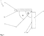
- Figures 1 and 2 show the schematic diagram of an exemplary embodiment of a display device 1 according to the invention for the interior of a motor vehicle.
- Display device 1 comprises a mechanical decorative member 2 with a side 2a facing an observer, for example the driver of a motor vehicle, and provided with mechanical elements, for example decorative elements and/or measurement devices.
- the mechanical elements are preferably static.
- Display device 1 further comprises - in the viewing direction of the observer, for example the driver of a motor vehicle - a semi-transparent mirror panel 3 arranged in front of mechanical decorative member 2, which is made from combiner glass and may have means for setting a tint.
- the semi-transparent mirror panel 3 may be electrically tinted itself, or it may have an additional electrical tinting film.
- the tint may be suitable for fading out the background depending on the content.
- display 4 for generating images is arranged such that the semi-transparent mirror panel 3 is located between the side 4a of the image output of display 4 and the mechanical decorative member 2.
- display 4 is positioned at an angle a to semi-transparent mirror panel 3 such that, if display 4 is turned on, a virtual display reflection 5 is generated by reflecting the display 4 on semi-transparent mirror panel 3, the plane of which being aligned at an angle b to display 4 which is larger than angle a.
- This virtual display reflection 5 is positioned within the observer's viewing direction above the observer-facing side 2a of mechanical decorative member 2 so that the mechanical decorative member 2 is overlapped by virtual display reflection 5.
- the observer-facing side 2a of mechanical decorative member 2 and the imaging-outputting side 4a of display 4 are positioned at a 90-degree angle to one another, according to the exemplary embodiment shown.
- Semi-transparent mirror panel 3, made from combiner glass, is arranged in the middle and makes it possible to project virtual reflection 5 onto mechanical decorative member 2.
Landscapes
- Engineering & Computer Science (AREA)
- Physics & Mathematics (AREA)
- Combustion & Propulsion (AREA)
- Chemical & Material Sciences (AREA)
- Transportation (AREA)
- Mechanical Engineering (AREA)
- General Physics & Mathematics (AREA)
- Optics & Photonics (AREA)
- Business, Economics & Management (AREA)
- Accounting & Taxation (AREA)
- Marketing (AREA)
- Theoretical Computer Science (AREA)
- Instrument Panels (AREA)
- Nonlinear Science (AREA)
Abstract
The invention relates to a display device (1) for the interior of a motor vehicle, comprising
• a mechanical decorative member (2) with an observer-facing side (2a) provided with mechanical elements,
• at least one semi-transparent mirror panel (3) arranged in front of the mechanical decorative member (2) in the observer's viewing direction, and
• a display (4) for generating images, arranged such that the semi-transparent mirror panel (3) is located between the side (4a) of the display (4) image output and the mechanical decorative member (2) and is arranged at an angle a to the display (4) such that, if the display (4) is turned on, a virtual display reflection (5) is generated by reflecting the display image on the semi-transparent mirror panel (3), the plane of which being positioned at an angle b to the display (4) which is larger than angle a, and above the observer-facing side (2a) of the mechanical decorative member (2) in the observer's viewing direction so that the mechanical decorative member is overlapped by the virtual display reflection (5), wherein, if the display (4) is turned off, the mechanical decorative member (2) with the mechanical elements is still visible to the observer.
• a mechanical decorative member (2) with an observer-facing side (2a) provided with mechanical elements,
• at least one semi-transparent mirror panel (3) arranged in front of the mechanical decorative member (2) in the observer's viewing direction, and
• a display (4) for generating images, arranged such that the semi-transparent mirror panel (3) is located between the side (4a) of the display (4) image output and the mechanical decorative member (2) and is arranged at an angle a to the display (4) such that, if the display (4) is turned on, a virtual display reflection (5) is generated by reflecting the display image on the semi-transparent mirror panel (3), the plane of which being positioned at an angle b to the display (4) which is larger than angle a, and above the observer-facing side (2a) of the mechanical decorative member (2) in the observer's viewing direction so that the mechanical decorative member is overlapped by the virtual display reflection (5), wherein, if the display (4) is turned off, the mechanical decorative member (2) with the mechanical elements is still visible to the observer.
This display device makes it possible to combine visual appeal with a high level of reconfigurability.
Description
- The invention relates to a display device for the interior of a motor vehicle. This display device makes it possible to combine visual appeal with a high level of reconfigurability.
- Motor vehicle drivers and passengers prefer high-quality mechanical elements, such as measurement instruments, which have the appearance of a high-quality Swiss watch. The disadvantage of such mechanical elements is that they are normally not reconfigurable. As such, many mechanical displays, such as tachometers and mechanical speed displays, are now being replaced with displays, that is to say, generally flat components used for visualization, which show context-related content.
- The problem with displays is that they appear flat and artificial. If a reconfigurable group display is turned off, it looks like a black hole without any attractive aspect. Furthermore, it is not possible to install large displays due to the conventional arrangement of displays next to mechanical devices. Yet, it is not advantageous to combine several small displays instead of using just one large display.
- Alternative devices which use a mechanical movement in order to turn mechanical measurement devices and thus bring displays to the front require moving parts, making these devices complex and prone to faults.
- The prior art discloses configurations in which a mechanical or electromechanical indicator instrument is partially covered with a virtual image. As an example,
WO2014/125546 A1 discloses a display device, comprising the following components: a display element with a display area, visible from the front side; a reflection element which is positioned in front of the display element and has semi-transparent properties; as well as an image output device which outputs an image in the direction of the reflection element to display a virtual image. A control unit is used to control the light emission of a light-emitting element such that a part of the display area which is covered by the virtual image when viewed from front to rear is darker than the part of the display area which is not covered by the virtual image when viewed from the same angle. -
US 2008 309 470 A1 describes a built-in instrument cluster for a motor vehicle having at least one display device which emits image-forming light and is arranged in a direct field of view of an observer, and at least one illuminated and/or self-illuminating electromechanical indicator device which is arranged at an angle to the display device in the observer's field of view and which is moved into the observer's field of view together with the display device by an optical combiner adapted to reflect the image-forming light of the electromechanical indicator device. To save overall depth for motor vehicle components abutting the electromechanical indicator device, the electromechanical indicator device at least partly includes light guides and/or light projectors. The optical combiner may be formed by a semi-transparent mirror, the display device being arranged behind the mirror in a viewing direction of the observer and the electromechanical indicator device being arranged below the mirror. -
DE 10 2005 011 094 A1 discloses a driver information system having a control unit with a plurality of functional elements and a display unit for the graphical representation of information at least relating to the control unit. The driver information system has a plurality of display modes for displaying the information displayed on the display unit. As such, the display unit has a semi-transparent mirror arranged at an angle, wherein a display is arranged behind the semi-transparent mirror in the driver's viewing direction, and physical circular instruments for the number of revolutions and speed are arranged in the driver's reflected viewing direction. - The object of the invention is to provide a display device with a reconfigurable display which is visually appealing both when turned off and when turned on.
- The object of the invention is achieved by a display device for the interior of a motor vehicle, having the features specified in claim 1. Any advantageous developments are specified in the subclaims.
- The solution according to the invention is a display device for the interior of a motor vehicle, comprising
- a mechanical decorative member with a side facing the observer and provided with mechanical elements,
- at least one semi-transparent mirror panel arranged in front of the mechanical decorative member and in the observer's viewing direction, and
- a display for generating images, arranged such that the semi-transparent mirror panel is located between the side of the display image output and the mechanical decorative member, and arranged at an angle a to the display such that a virtual display reflection is generated when the display is turned on by reflecting the display image on the semi-transparent mirror panel, the plane of which being positioned at an angle b to the display which is larger than the angle a and located above the side of the mechanical decorative member facing the observer in the observer's viewing direction, so that the mechanical decorative member is overlapped by the virtual display reflection, wherein the mechanical decorative member with the mechanical elements is still visible to the observer when the display is turned off.
- According to the concept of the invention, a virtual image with one or more pieces of virtual information is projected onto a backdrop provided with mechanical elements, that is physically real elements. As such, a decorative member formed with mechanical elements is used as a backdrop, fulfilling a design or aesthetic purpose when the device is turned off. This means that the aesthetics of the mechanical decorative member are maintained as such even if the power is turned off. The concept according to the invention of overlapping mechanical, that is physical, elements with virtual information makes it possible to combine high-quality craftsmanship, in terms of the design for the decorative member, with a high level of display reconfigurability.
- When the device is turned on, the virtual image is generated which is located above the mechanical decoration. The virtual image is generated by reflecting the display on a semi-transparent mirror panel and creating an appropriate overlap, wherein the preferably precise overlap of the decorative member with the virtual display reflection as a virtual image creates the impression as if the decorative member is moving or dynamically changing. In this way, it is possible to limit the number of mechanical movements required in the display device. Thus, for example, indicators can be animated on the display as if they had been placed onto the mechanical elements. However, the electronics relevant for the display device are not located in the decorative member, but rather in the display, which is reflected, as well as in the connected components. The structure of the display device according to the invention therefore makes it possible to reduce complexity compared with the prior art. At the same time, the number of displays required can be limited to one display. One main advantage is that the entire display surface can be used to display reconfigurable content.
- Furthermore, the structure according to the invention allows high-quality mechanical decoration to be implemented, giving the observer a good perception of the equipment and featuring depth, precision and details which cannot be produced on displays. Overlapping the virtual image and mechanical decoration creates a holographic effect, whereby the decorative member appears dynamically for the observer.
- The mechanical elements in the decorative member can be illuminated, however, the decorative member does not include any displays. If the mechanical elements of the decorative member are not illuminated from behind, it is possible to virtually project texture and lighting onto them via the display. This enables a high degree of reconfigurability.
- The decorative member can include moving elements, however, the mechanical elements are preferably static. If the observer looks into the semi-transparent mirror panel, the display reflection lies above the mechanical elements of the mechanical decoration. This results in a good reconfigurability of the display. If the display is turned off, the observer looks directly at the mechanical decorative member through the semi-transparent mirror panel. In this way, the display device assembly still looks appealing when the power has been turned off and creates a first-class look.
- According to an advantageous embodiment of the invention, the semi-transparent mirror panel is made from combiner glass. As is known, a combiner is made of a reflecting, transparent panel.
- The display device may also have at least one means for setting a tint of the semi-transparent mirror panel. As such, the semi-transparent mirror panel may be electrically toned itself, for example, and/or may have an additional electrical tinting film. This tint may be suitable for fading out the background depending on the content.
- The surface of the decorative member facing the observer and the side of the display showing the image are preferably positioned at a 90-degree angle to each other. The semi-transparent mirror panel is positioned in the middle, allowing the virtual reflection to be projected onto the mechanical decorative member. As such, the semi-transparent mirror panel is preferably arranged such that the plane of the virtual display reflection overlapping the mechanical decorative member and its mechanical elements is also positioned at an angle b = 90 degrees to the display as an image source for the virtual reflection.
- According to a further design of the invention, the display device only comprises one display, but several semi-transparent mirror panels to generate multiple virtual levels.
- The invention will now be further described, by way of example only, with reference to the accompanying drawings, in which:
-
Figure 1 shows a schematic diagram of an embodiment of an instrument display device according to the invention in a side view, and -
Figure 2 shows a schematic diagram of an embodiment of the instrument display - device according to the invention in a perspective front view.
-
Figures 1 and2 show the schematic diagram of an exemplary embodiment of a display device 1 according to the invention for the interior of a motor vehicle. Display device 1 comprises a mechanicaldecorative member 2 with aside 2a facing an observer, for example the driver of a motor vehicle, and provided with mechanical elements, for example decorative elements and/or measurement devices. The mechanical elements are preferably static. - Display device 1 further comprises - in the viewing direction of the observer, for example the driver of a motor vehicle - a
semi-transparent mirror panel 3 arranged in front of mechanicaldecorative member 2, which is made from combiner glass and may have means for setting a tint. As such, thesemi-transparent mirror panel 3 may be electrically tinted itself, or it may have an additional electrical tinting film. The tint may be suitable for fading out the background depending on the content. - Furthermore, display 4 for generating images is arranged such that the
semi-transparent mirror panel 3 is located between theside 4a of the image output of display 4 and the mechanicaldecorative member 2. As such, display 4 is positioned at an angle a tosemi-transparent mirror panel 3 such that, if display 4 is turned on, avirtual display reflection 5 is generated by reflecting the display 4 onsemi-transparent mirror panel 3, the plane of which being aligned at an angle b to display 4 which is larger than angle a. Thisvirtual display reflection 5 is positioned within the observer's viewing direction above the observer-facingside 2a of mechanicaldecorative member 2 so that the mechanicaldecorative member 2 is overlapped byvirtual display reflection 5. - The observer-facing
side 2a of mechanicaldecorative member 2 and the imaging-outputtingside 4a of display 4 are positioned at a 90-degree angle to one another, according to the exemplary embodiment shown.Semi-transparent mirror panel 3, made from combiner glass, is arranged in the middle and makes it possible to projectvirtual reflection 5 onto mechanicaldecorative member 2. As such,semi-transparent mirror panel 3 is arranged such that adisplay reflection 5 is generated as a virtual image by reflecting the display image on the reflecting combiner glass of semi-transparent mirror panel 4, this reflection being aligned at an angle b = 90 degrees to the plane of display 4 and being located abovedecorative member 2. More specifically, if the observer looks into the combiner glass, the display image is reflected anddisplay reflection 5 appears at a virtual plane which overlaps the mechanical elements ofdecorative member 2. In this way, moving indicators animated on display 4, for example, can be reflected as if they were placed on the mechanical elements ofdecorative member 2. -
- 1
- Display device
- 2
- Mechanical decorative member
- 2a
- Observer-facing side of
decorative member 2 - 3
- Semi-transparent mirror panel
- 4
- Display
- 4a
- Side of the image output for display 4
- 5
- Virtual reflection, display reflection
Claims (9)
- A display device (1) for the interior of a motor vehicle, comprising• a mechanical decorative member (2) with an observer-facing side (2a) provided with mechanical elements,• at least one semi-transparent mirror panel (3) arranged in front of the mechanical decorative member (2) in the observer's viewing direction, and• a display (4) for generating images, arranged such that the semi-transparent mirror panel (3) is located between the side (4a) of the display (4) image output and the mechanical decorative member (2) and is arranged at an angle a to the display (4) such that, if the display (4) is turned on, a virtual display reflection (5) is generated by reflecting the display image on the semi-transparent mirror panel (3), the plane of which being positioned at an angle b to the display (4) which is larger than angle a, and above the observer-facing side (2a) of the mechanical decorative member (2) in the observer's viewing direction so that the mechanical decorative member is overlapped by the virtual display reflection (5) and wherein, if the display (4) is turned off, the mechanical decorative member (2) with the mechanical elements is still visible to the observer.
- The display device (1) according to claim 1, characterized in that the mechanical elements of decorative member (2) are illuminated.
- The display device (1) according to claim 1, characterized in that the mechanical elements of the decorative member (2) are static.
- The display device (1) according to any preceding claim, characterized in that the semi-transparent mirror panel (3) is made from combiner glass.
- The display device (1) according to any preceding claim, characterized in that the display device has at least one means for tinting the semi-transparent mirror panel (3).
- The display device (1) according to claim 5, characterized in that the semi-transparent mirror panel (3) can be tinted electrically.
- The display device (1) according to claim 5 or claim 6, characterized in that the semi-transparent mirror panel (3) is provided with an electrical tinting film.
- The display device (1) according to any preceding claim, characterized in that the semi-transparent mirror panel (3) is arranged such that the plane of the virtual reflection (5) overlapping the mechanical decorative member (2) and its mechanical elements is aligned at an angle b = 90 degrees to the display (4) as an image source for the virtual reflection (5).
- The display device (1) according to any preceding claim, characterized in that the display device (1) only comprises one display (4), but several semi-transparent mirror panels (3) to generate multiple virtual levels.
Applications Claiming Priority (1)
| Application Number | Priority Date | Filing Date | Title |
|---|---|---|---|
| DE102017101980.4A DE102017101980A1 (en) | 2017-02-01 | 2017-02-01 | Display device for the interior of a motor vehicle |
Publications (1)
| Publication Number | Publication Date |
|---|---|
| EP3357736A1 true EP3357736A1 (en) | 2018-08-08 |
Family
ID=61132352
Family Applications (1)
| Application Number | Title | Priority Date | Filing Date |
|---|---|---|---|
| EP18154785.2A Withdrawn EP3357736A1 (en) | 2017-02-01 | 2018-02-01 | Display device for the interior of a motor vehicle |
Country Status (4)
| Country | Link |
|---|---|
| US (1) | US10416465B2 (en) |
| EP (1) | EP3357736A1 (en) |
| CN (1) | CN108375831A (en) |
| DE (1) | DE102017101980A1 (en) |
Families Citing this family (2)
| Publication number | Priority date | Publication date | Assignee | Title |
|---|---|---|---|---|
| KR102784317B1 (en) | 2019-07-30 | 2025-03-24 | 삼성디스플레이 주식회사 | Display device |
| DE102019211518B3 (en) | 2019-08-01 | 2020-08-20 | Audi Ag | Display device for a motor vehicle and motor vehicle with a display device |
Citations (6)
| Publication number | Priority date | Publication date | Assignee | Title |
|---|---|---|---|---|
| EP0648639A1 (en) * | 1993-10-13 | 1995-04-19 | Robert Bosch Gmbh | Display arrangement for motor vehicles |
| FR2727559A1 (en) * | 1994-11-25 | 1996-05-31 | Magneti Marelli France | DISPLAY DEVICE FOR MOTOR VEHICLE |
| EP1342605A1 (en) * | 2002-03-04 | 2003-09-10 | Ford Global Technologies, Inc., A subsidiary of Ford Motor Company | Device for controlling a screen display |
| JP2004233701A (en) * | 2003-01-31 | 2004-08-19 | Nippon Seiki Co Ltd | Display device |
| DE102008037061A1 (en) * | 2008-08-08 | 2010-02-11 | Bayerische Motoren Werke Aktiengesellschaft | Motor vehicle navigation system, has control device designed for controlling display device such that sequential information objects are displayed on layers of display device simultaneously based on temporal and/or local sequence |
| FR2957860A1 (en) * | 2010-03-26 | 2011-09-30 | Valeo Systemes Thermiques | Displaying unit for man-machine interface of motor vehicle to reveal operational condition of e.g. seat of vehicle for driver of vehicle using pictogram, has two films, where second film is associated with second control unit of portion |
Family Cites Families (6)
| Publication number | Priority date | Publication date | Assignee | Title |
|---|---|---|---|---|
| CA2306915A1 (en) | 1997-11-03 | 1999-05-14 | Douglas Hall | Virtual instrument panel |
| EP1462297A3 (en) | 2003-03-26 | 2007-05-09 | Calsonic Kansei Corporation | Information displaying apparatus for a vehicle |
| DE102005011094A1 (en) | 2004-03-29 | 2005-11-03 | Volkswagen Ag | Driver information system |
| US20080309470A1 (en) | 2004-04-05 | 2008-12-18 | Thomas Kiesewetter | Built-in instrument cluster |
| DE102005026872A1 (en) | 2005-06-10 | 2006-12-14 | GM Global Technology Operations, Inc., Detroit | Motor vehicle tail gate arrangement, has tail gate hinged at strengthened B-column bow connecting B-column, supported by rear roof cross beam, and glass pane of tail gate engaged partially with electrical tinged foil |
| JP5904137B2 (en) | 2013-02-12 | 2016-04-13 | 株式会社デンソー | Vehicle display device |
-
2017
- 2017-02-01 DE DE102017101980.4A patent/DE102017101980A1/en not_active Withdrawn
-
2018
- 2018-02-01 CN CN201810102414.3A patent/CN108375831A/en active Pending
- 2018-02-01 EP EP18154785.2A patent/EP3357736A1/en not_active Withdrawn
- 2018-02-01 US US15/886,101 patent/US10416465B2/en not_active Expired - Fee Related
Patent Citations (6)
| Publication number | Priority date | Publication date | Assignee | Title |
|---|---|---|---|---|
| EP0648639A1 (en) * | 1993-10-13 | 1995-04-19 | Robert Bosch Gmbh | Display arrangement for motor vehicles |
| FR2727559A1 (en) * | 1994-11-25 | 1996-05-31 | Magneti Marelli France | DISPLAY DEVICE FOR MOTOR VEHICLE |
| EP1342605A1 (en) * | 2002-03-04 | 2003-09-10 | Ford Global Technologies, Inc., A subsidiary of Ford Motor Company | Device for controlling a screen display |
| JP2004233701A (en) * | 2003-01-31 | 2004-08-19 | Nippon Seiki Co Ltd | Display device |
| DE102008037061A1 (en) * | 2008-08-08 | 2010-02-11 | Bayerische Motoren Werke Aktiengesellschaft | Motor vehicle navigation system, has control device designed for controlling display device such that sequential information objects are displayed on layers of display device simultaneously based on temporal and/or local sequence |
| FR2957860A1 (en) * | 2010-03-26 | 2011-09-30 | Valeo Systemes Thermiques | Displaying unit for man-machine interface of motor vehicle to reveal operational condition of e.g. seat of vehicle for driver of vehicle using pictogram, has two films, where second film is associated with second control unit of portion |
Also Published As
| Publication number | Publication date |
|---|---|
| US10416465B2 (en) | 2019-09-17 |
| DE102017101980A1 (en) | 2018-08-02 |
| US20180217388A1 (en) | 2018-08-02 |
| CN108375831A (en) | 2018-08-07 |
Similar Documents
| Publication | Publication Date | Title |
|---|---|---|
| KR101939506B1 (en) | Display device | |
| CN112639573B (en) | Method for operating a visual display device for a motor vehicle | |
| CN106536255B (en) | Display device | |
| US10953748B2 (en) | Multi-layer display for vehicle dash | |
| CN110892310A (en) | Motor vehicle display device and motor vehicle | |
| JP6122694B2 (en) | In-vehicle display device | |
| US10416465B2 (en) | Display device employing a virtual plane overlaying mechanical indicia | |
| WO2016035304A1 (en) | Display device | |
| JP2017078668A (en) | Display | |
| CN108621795A (en) | Display device for vehicle | |
| JP5408103B2 (en) | Vehicle display device | |
| JP3036596B1 (en) | Display device | |
| JP5187553B2 (en) | Display device | |
| JP6409427B2 (en) | Vehicle display device | |
| JPH04287728A (en) | Head up display device | |
| JP6476803B2 (en) | Display device | |
| JP6264360B2 (en) | Display device | |
| JP2014224757A (en) | Vehicle display device | |
| JP2004093637A (en) | Display device | |
| JP2008196908A (en) | Instrument display board | |
| JPWO2016163316A1 (en) | Vehicle display device | |
| JP6477046B2 (en) | Display device | |
| JP2015160570A (en) | Head-up display device | |
| JP2006103508A (en) | Vehicle display device | |
| JP2005283542A (en) | Display device |
Legal Events
| Date | Code | Title | Description |
|---|---|---|---|
| PUAI | Public reference made under article 153(3) epc to a published international application that has entered the european phase |
Free format text: ORIGINAL CODE: 0009012 |
|
| AK | Designated contracting states |
Kind code of ref document: A1 Designated state(s): AL AT BE BG CH CY CZ DE DK EE ES FI FR GB GR HR HU IE IS IT LI LT LU LV MC MK MT NL NO PL PT RO RS SE SI SK SM TR |
|
| AX | Request for extension of the european patent |
Extension state: BA ME |
|
| STAA | Information on the status of an ep patent application or granted ep patent |
Free format text: STATUS: THE APPLICATION IS DEEMED TO BE WITHDRAWN |
|
| 18D | Application deemed to be withdrawn |
Effective date: 20190209 |