EP3357688A1 - Resin molded article, method for manufacturing resin molded article, and device for manufacturing resin molded article - Google Patents
Resin molded article, method for manufacturing resin molded article, and device for manufacturing resin molded article Download PDFInfo
- Publication number
- EP3357688A1 EP3357688A1 EP16850832.3A EP16850832A EP3357688A1 EP 3357688 A1 EP3357688 A1 EP 3357688A1 EP 16850832 A EP16850832 A EP 16850832A EP 3357688 A1 EP3357688 A1 EP 3357688A1
- Authority
- EP
- European Patent Office
- Prior art keywords
- resin
- molded
- surface skin
- skin member
- resin surface
- Prior art date
- Legal status (The legal status is an assumption and is not a legal conclusion. Google has not performed a legal analysis and makes no representation as to the accuracy of the status listed.)
- Granted
Links
Images






Classifications
-
- B—PERFORMING OPERATIONS; TRANSPORTING
- B32—LAYERED PRODUCTS
- B32B—LAYERED PRODUCTS, i.e. PRODUCTS BUILT-UP OF STRATA OF FLAT OR NON-FLAT, e.g. CELLULAR OR HONEYCOMB, FORM
- B32B27/00—Layered products comprising a layer of synthetic resin
- B32B27/12—Layered products comprising a layer of synthetic resin next to a fibrous or filamentary layer
-
- B—PERFORMING OPERATIONS; TRANSPORTING
- B29—WORKING OF PLASTICS; WORKING OF SUBSTANCES IN A PLASTIC STATE IN GENERAL
- B29C—SHAPING OR JOINING OF PLASTICS; SHAPING OF MATERIAL IN A PLASTIC STATE, NOT OTHERWISE PROVIDED FOR; AFTER-TREATMENT OF THE SHAPED PRODUCTS, e.g. REPAIRING
- B29C51/00—Shaping by thermoforming, i.e. shaping sheets or sheet like preforms after heating, e.g. shaping sheets in matched moulds or by deep-drawing; Apparatus therefor
- B29C51/08—Deep drawing or matched-mould forming, i.e. using mechanical means only
-
- B—PERFORMING OPERATIONS; TRANSPORTING
- B29—WORKING OF PLASTICS; WORKING OF SUBSTANCES IN A PLASTIC STATE IN GENERAL
- B29C—SHAPING OR JOINING OF PLASTICS; SHAPING OF MATERIAL IN A PLASTIC STATE, NOT OTHERWISE PROVIDED FOR; AFTER-TREATMENT OF THE SHAPED PRODUCTS, e.g. REPAIRING
- B29C51/00—Shaping by thermoforming, i.e. shaping sheets or sheet like preforms after heating, e.g. shaping sheets in matched moulds or by deep-drawing; Apparatus therefor
- B29C51/10—Forming by pressure difference, e.g. vacuum
-
- B—PERFORMING OPERATIONS; TRANSPORTING
- B29—WORKING OF PLASTICS; WORKING OF SUBSTANCES IN A PLASTIC STATE IN GENERAL
- B29C—SHAPING OR JOINING OF PLASTICS; SHAPING OF MATERIAL IN A PLASTIC STATE, NOT OTHERWISE PROVIDED FOR; AFTER-TREATMENT OF THE SHAPED PRODUCTS, e.g. REPAIRING
- B29C65/00—Joining or sealing of preformed parts, e.g. welding of plastics materials; Apparatus therefor
- B29C65/02—Joining or sealing of preformed parts, e.g. welding of plastics materials; Apparatus therefor by heating, with or without pressure
- B29C65/40—Applying molten plastics, e.g. hot melt
-
- B—PERFORMING OPERATIONS; TRANSPORTING
- B32—LAYERED PRODUCTS
- B32B—LAYERED PRODUCTS, i.e. PRODUCTS BUILT-UP OF STRATA OF FLAT OR NON-FLAT, e.g. CELLULAR OR HONEYCOMB, FORM
- B32B27/00—Layered products comprising a layer of synthetic resin
- B32B27/30—Layered products comprising a layer of synthetic resin comprising vinyl (co)polymers; comprising acrylic (co)polymers
- B32B27/302—Layered products comprising a layer of synthetic resin comprising vinyl (co)polymers; comprising acrylic (co)polymers comprising aromatic vinyl (co)polymers, e.g. styrenic (co)polymers
-
- B—PERFORMING OPERATIONS; TRANSPORTING
- B32—LAYERED PRODUCTS
- B32B—LAYERED PRODUCTS, i.e. PRODUCTS BUILT-UP OF STRATA OF FLAT OR NON-FLAT, e.g. CELLULAR OR HONEYCOMB, FORM
- B32B27/00—Layered products comprising a layer of synthetic resin
- B32B27/30—Layered products comprising a layer of synthetic resin comprising vinyl (co)polymers; comprising acrylic (co)polymers
- B32B27/304—Layered products comprising a layer of synthetic resin comprising vinyl (co)polymers; comprising acrylic (co)polymers comprising vinyl halide (co)polymers, e.g. PVC, PVDC, PVF, PVDF
-
- B—PERFORMING OPERATIONS; TRANSPORTING
- B32—LAYERED PRODUCTS
- B32B—LAYERED PRODUCTS, i.e. PRODUCTS BUILT-UP OF STRATA OF FLAT OR NON-FLAT, e.g. CELLULAR OR HONEYCOMB, FORM
- B32B27/00—Layered products comprising a layer of synthetic resin
- B32B27/30—Layered products comprising a layer of synthetic resin comprising vinyl (co)polymers; comprising acrylic (co)polymers
- B32B27/308—Layered products comprising a layer of synthetic resin comprising vinyl (co)polymers; comprising acrylic (co)polymers comprising acrylic (co)polymers
-
- B—PERFORMING OPERATIONS; TRANSPORTING
- B32—LAYERED PRODUCTS
- B32B—LAYERED PRODUCTS, i.e. PRODUCTS BUILT-UP OF STRATA OF FLAT OR NON-FLAT, e.g. CELLULAR OR HONEYCOMB, FORM
- B32B27/00—Layered products comprising a layer of synthetic resin
- B32B27/32—Layered products comprising a layer of synthetic resin comprising polyolefins
-
- B—PERFORMING OPERATIONS; TRANSPORTING
- B32—LAYERED PRODUCTS
- B32B—LAYERED PRODUCTS, i.e. PRODUCTS BUILT-UP OF STRATA OF FLAT OR NON-FLAT, e.g. CELLULAR OR HONEYCOMB, FORM
- B32B27/00—Layered products comprising a layer of synthetic resin
- B32B27/36—Layered products comprising a layer of synthetic resin comprising polyesters
-
- B—PERFORMING OPERATIONS; TRANSPORTING
- B32—LAYERED PRODUCTS
- B32B—LAYERED PRODUCTS, i.e. PRODUCTS BUILT-UP OF STRATA OF FLAT OR NON-FLAT, e.g. CELLULAR OR HONEYCOMB, FORM
- B32B27/00—Layered products comprising a layer of synthetic resin
- B32B27/36—Layered products comprising a layer of synthetic resin comprising polyesters
- B32B27/365—Layered products comprising a layer of synthetic resin comprising polyesters comprising polycarbonates
-
- B—PERFORMING OPERATIONS; TRANSPORTING
- B32—LAYERED PRODUCTS
- B32B—LAYERED PRODUCTS, i.e. PRODUCTS BUILT-UP OF STRATA OF FLAT OR NON-FLAT, e.g. CELLULAR OR HONEYCOMB, FORM
- B32B27/00—Layered products comprising a layer of synthetic resin
- B32B27/40—Layered products comprising a layer of synthetic resin comprising polyurethanes
-
- B—PERFORMING OPERATIONS; TRANSPORTING
- B32—LAYERED PRODUCTS
- B32B—LAYERED PRODUCTS, i.e. PRODUCTS BUILT-UP OF STRATA OF FLAT OR NON-FLAT, e.g. CELLULAR OR HONEYCOMB, FORM
- B32B37/00—Methods or apparatus for laminating, e.g. by curing or by ultrasonic bonding
- B32B37/10—Methods or apparatus for laminating, e.g. by curing or by ultrasonic bonding characterised by the pressing technique, e.g. using action of vacuum or fluid pressure
-
- B—PERFORMING OPERATIONS; TRANSPORTING
- B32—LAYERED PRODUCTS
- B32B—LAYERED PRODUCTS, i.e. PRODUCTS BUILT-UP OF STRATA OF FLAT OR NON-FLAT, e.g. CELLULAR OR HONEYCOMB, FORM
- B32B37/00—Methods or apparatus for laminating, e.g. by curing or by ultrasonic bonding
- B32B37/12—Methods or apparatus for laminating, e.g. by curing or by ultrasonic bonding characterised by using adhesives
-
- B—PERFORMING OPERATIONS; TRANSPORTING
- B32—LAYERED PRODUCTS
- B32B—LAYERED PRODUCTS, i.e. PRODUCTS BUILT-UP OF STRATA OF FLAT OR NON-FLAT, e.g. CELLULAR OR HONEYCOMB, FORM
- B32B5/00—Layered products characterised by the non- homogeneity or physical structure, i.e. comprising a fibrous, filamentary, particulate or foam layer; Layered products characterised by having a layer differing constitutionally or physically in different parts
- B32B5/02—Layered products characterised by the non- homogeneity or physical structure, i.e. comprising a fibrous, filamentary, particulate or foam layer; Layered products characterised by having a layer differing constitutionally or physically in different parts characterised by structural features of a fibrous or filamentary layer
-
- B—PERFORMING OPERATIONS; TRANSPORTING
- B32—LAYERED PRODUCTS
- B32B—LAYERED PRODUCTS, i.e. PRODUCTS BUILT-UP OF STRATA OF FLAT OR NON-FLAT, e.g. CELLULAR OR HONEYCOMB, FORM
- B32B7/00—Layered products characterised by the relation between layers; Layered products characterised by the relative orientation of features between layers, or by the relative values of a measurable parameter between layers, i.e. products comprising layers having different physical, chemical or physicochemical properties; Layered products characterised by the interconnection of layers
- B32B7/04—Interconnection of layers
- B32B7/12—Interconnection of layers using interposed adhesives or interposed materials with bonding properties
-
- C—CHEMISTRY; METALLURGY
- C08—ORGANIC MACROMOLECULAR COMPOUNDS; THEIR PREPARATION OR CHEMICAL WORKING-UP; COMPOSITIONS BASED THEREON
- C08J—WORKING-UP; GENERAL PROCESSES OF COMPOUNDING; AFTER-TREATMENT NOT COVERED BY SUBCLASSES C08B, C08C, C08F, C08G or C08H
- C08J5/00—Manufacture of articles or shaped materials containing macromolecular substances
- C08J5/04—Reinforcing macromolecular compounds with loose or coherent fibrous material
-
- B—PERFORMING OPERATIONS; TRANSPORTING
- B29—WORKING OF PLASTICS; WORKING OF SUBSTANCES IN A PLASTIC STATE IN GENERAL
- B29C—SHAPING OR JOINING OF PLASTICS; SHAPING OF MATERIAL IN A PLASTIC STATE, NOT OTHERWISE PROVIDED FOR; AFTER-TREATMENT OF THE SHAPED PRODUCTS, e.g. REPAIRING
- B29C2791/00—Shaping characteristics in general
- B29C2791/004—Shaping under special conditions
- B29C2791/006—Using vacuum
-
- B—PERFORMING OPERATIONS; TRANSPORTING
- B29—WORKING OF PLASTICS; WORKING OF SUBSTANCES IN A PLASTIC STATE IN GENERAL
- B29C—SHAPING OR JOINING OF PLASTICS; SHAPING OF MATERIAL IN A PLASTIC STATE, NOT OTHERWISE PROVIDED FOR; AFTER-TREATMENT OF THE SHAPED PRODUCTS, e.g. REPAIRING
- B29C51/00—Shaping by thermoforming, i.e. shaping sheets or sheet like preforms after heating, e.g. shaping sheets in matched moulds or by deep-drawing; Apparatus therefor
- B29C51/04—Combined thermoforming and prestretching, e.g. biaxial stretching
-
- B—PERFORMING OPERATIONS; TRANSPORTING
- B29—WORKING OF PLASTICS; WORKING OF SUBSTANCES IN A PLASTIC STATE IN GENERAL
- B29C—SHAPING OR JOINING OF PLASTICS; SHAPING OF MATERIAL IN A PLASTIC STATE, NOT OTHERWISE PROVIDED FOR; AFTER-TREATMENT OF THE SHAPED PRODUCTS, e.g. REPAIRING
- B29C51/00—Shaping by thermoforming, i.e. shaping sheets or sheet like preforms after heating, e.g. shaping sheets in matched moulds or by deep-drawing; Apparatus therefor
- B29C51/12—Shaping by thermoforming, i.e. shaping sheets or sheet like preforms after heating, e.g. shaping sheets in matched moulds or by deep-drawing; Apparatus therefor of articles having inserts or reinforcements
-
- B—PERFORMING OPERATIONS; TRANSPORTING
- B29—WORKING OF PLASTICS; WORKING OF SUBSTANCES IN A PLASTIC STATE IN GENERAL
- B29C—SHAPING OR JOINING OF PLASTICS; SHAPING OF MATERIAL IN A PLASTIC STATE, NOT OTHERWISE PROVIDED FOR; AFTER-TREATMENT OF THE SHAPED PRODUCTS, e.g. REPAIRING
- B29C51/00—Shaping by thermoforming, i.e. shaping sheets or sheet like preforms after heating, e.g. shaping sheets in matched moulds or by deep-drawing; Apparatus therefor
- B29C51/14—Shaping by thermoforming, i.e. shaping sheets or sheet like preforms after heating, e.g. shaping sheets in matched moulds or by deep-drawing; Apparatus therefor using multilayered preforms or sheets
-
- B—PERFORMING OPERATIONS; TRANSPORTING
- B29—WORKING OF PLASTICS; WORKING OF SUBSTANCES IN A PLASTIC STATE IN GENERAL
- B29C—SHAPING OR JOINING OF PLASTICS; SHAPING OF MATERIAL IN A PLASTIC STATE, NOT OTHERWISE PROVIDED FOR; AFTER-TREATMENT OF THE SHAPED PRODUCTS, e.g. REPAIRING
- B29C51/00—Shaping by thermoforming, i.e. shaping sheets or sheet like preforms after heating, e.g. shaping sheets in matched moulds or by deep-drawing; Apparatus therefor
- B29C51/16—Lining or labelling
-
- B—PERFORMING OPERATIONS; TRANSPORTING
- B29—WORKING OF PLASTICS; WORKING OF SUBSTANCES IN A PLASTIC STATE IN GENERAL
- B29C—SHAPING OR JOINING OF PLASTICS; SHAPING OF MATERIAL IN A PLASTIC STATE, NOT OTHERWISE PROVIDED FOR; AFTER-TREATMENT OF THE SHAPED PRODUCTS, e.g. REPAIRING
- B29C51/00—Shaping by thermoforming, i.e. shaping sheets or sheet like preforms after heating, e.g. shaping sheets in matched moulds or by deep-drawing; Apparatus therefor
- B29C51/26—Component parts, details or accessories; Auxiliary operations
- B29C51/264—Auxiliary operations prior to the thermoforming operation, e.g. cutting
-
- B—PERFORMING OPERATIONS; TRANSPORTING
- B29—WORKING OF PLASTICS; WORKING OF SUBSTANCES IN A PLASTIC STATE IN GENERAL
- B29C—SHAPING OR JOINING OF PLASTICS; SHAPING OF MATERIAL IN A PLASTIC STATE, NOT OTHERWISE PROVIDED FOR; AFTER-TREATMENT OF THE SHAPED PRODUCTS, e.g. REPAIRING
- B29C51/00—Shaping by thermoforming, i.e. shaping sheets or sheet like preforms after heating, e.g. shaping sheets in matched moulds or by deep-drawing; Apparatus therefor
- B29C51/26—Component parts, details or accessories; Auxiliary operations
- B29C51/46—Measuring, controlling or regulating
-
- B—PERFORMING OPERATIONS; TRANSPORTING
- B29—WORKING OF PLASTICS; WORKING OF SUBSTANCES IN A PLASTIC STATE IN GENERAL
- B29C—SHAPING OR JOINING OF PLASTICS; SHAPING OF MATERIAL IN A PLASTIC STATE, NOT OTHERWISE PROVIDED FOR; AFTER-TREATMENT OF THE SHAPED PRODUCTS, e.g. REPAIRING
- B29C63/00—Lining or sheathing, i.e. applying preformed layers or sheathings of plastics; Apparatus therefor
- B29C63/02—Lining or sheathing, i.e. applying preformed layers or sheathings of plastics; Apparatus therefor using sheet or web-like material
-
- B—PERFORMING OPERATIONS; TRANSPORTING
- B29—WORKING OF PLASTICS; WORKING OF SUBSTANCES IN A PLASTIC STATE IN GENERAL
- B29K—INDEXING SCHEME ASSOCIATED WITH SUBCLASSES B29B, B29C OR B29D, RELATING TO MOULDING MATERIALS OR TO MATERIALS FOR MOULDS, REINFORCEMENTS, FILLERS OR PREFORMED PARTS, e.g. INSERTS
- B29K2105/00—Condition, form or state of moulded material or of the material to be shaped
- B29K2105/0097—Glues or adhesives, e.g. hot melts or thermofusible adhesives
-
- B—PERFORMING OPERATIONS; TRANSPORTING
- B29—WORKING OF PLASTICS; WORKING OF SUBSTANCES IN A PLASTIC STATE IN GENERAL
- B29K—INDEXING SCHEME ASSOCIATED WITH SUBCLASSES B29B, B29C OR B29D, RELATING TO MOULDING MATERIALS OR TO MATERIALS FOR MOULDS, REINFORCEMENTS, FILLERS OR PREFORMED PARTS, e.g. INSERTS
- B29K2105/00—Condition, form or state of moulded material or of the material to be shaped
- B29K2105/06—Condition, form or state of moulded material or of the material to be shaped containing reinforcements, fillers or inserts
-
- B—PERFORMING OPERATIONS; TRANSPORTING
- B29—WORKING OF PLASTICS; WORKING OF SUBSTANCES IN A PLASTIC STATE IN GENERAL
- B29K—INDEXING SCHEME ASSOCIATED WITH SUBCLASSES B29B, B29C OR B29D, RELATING TO MOULDING MATERIALS OR TO MATERIALS FOR MOULDS, REINFORCEMENTS, FILLERS OR PREFORMED PARTS, e.g. INSERTS
- B29K2995/00—Properties of moulding materials, reinforcements, fillers, preformed parts or moulds
- B29K2995/0018—Properties of moulding materials, reinforcements, fillers, preformed parts or moulds having particular optical properties, e.g. fluorescent or phosphorescent
- B29K2995/0022—Bright, glossy or shiny surface
-
- B—PERFORMING OPERATIONS; TRANSPORTING
- B29—WORKING OF PLASTICS; WORKING OF SUBSTANCES IN A PLASTIC STATE IN GENERAL
- B29L—INDEXING SCHEME ASSOCIATED WITH SUBCLASS B29C, RELATING TO PARTICULAR ARTICLES
- B29L2031/00—Other particular articles
- B29L2031/30—Vehicles, e.g. ships or aircraft, or body parts thereof
-
- B—PERFORMING OPERATIONS; TRANSPORTING
- B29—WORKING OF PLASTICS; WORKING OF SUBSTANCES IN A PLASTIC STATE IN GENERAL
- B29L—INDEXING SCHEME ASSOCIATED WITH SUBCLASS B29C, RELATING TO PARTICULAR ARTICLES
- B29L2031/00—Other particular articles
- B29L2031/30—Vehicles, e.g. ships or aircraft, or body parts thereof
- B29L2031/3005—Body finishings
-
- B—PERFORMING OPERATIONS; TRANSPORTING
- B29—WORKING OF PLASTICS; WORKING OF SUBSTANCES IN A PLASTIC STATE IN GENERAL
- B29L—INDEXING SCHEME ASSOCIATED WITH SUBCLASS B29C, RELATING TO PARTICULAR ARTICLES
- B29L2031/00—Other particular articles
- B29L2031/52—Sports equipment ; Games; Articles for amusement; Toys
-
- B—PERFORMING OPERATIONS; TRANSPORTING
- B32—LAYERED PRODUCTS
- B32B—LAYERED PRODUCTS, i.e. PRODUCTS BUILT-UP OF STRATA OF FLAT OR NON-FLAT, e.g. CELLULAR OR HONEYCOMB, FORM
- B32B2262/00—Composition or structural features of fibres which form a fibrous or filamentary layer or are present as additives
- B32B2262/10—Inorganic fibres
- B32B2262/101—Glass fibres
-
- B—PERFORMING OPERATIONS; TRANSPORTING
- B32—LAYERED PRODUCTS
- B32B—LAYERED PRODUCTS, i.e. PRODUCTS BUILT-UP OF STRATA OF FLAT OR NON-FLAT, e.g. CELLULAR OR HONEYCOMB, FORM
- B32B2262/00—Composition or structural features of fibres which form a fibrous or filamentary layer or are present as additives
- B32B2262/10—Inorganic fibres
- B32B2262/106—Carbon fibres, e.g. graphite fibres
-
- B—PERFORMING OPERATIONS; TRANSPORTING
- B32—LAYERED PRODUCTS
- B32B—LAYERED PRODUCTS, i.e. PRODUCTS BUILT-UP OF STRATA OF FLAT OR NON-FLAT, e.g. CELLULAR OR HONEYCOMB, FORM
- B32B2307/00—Properties of the layers or laminate
- B32B2307/70—Other properties
- B32B2307/732—Dimensional properties
-
- B—PERFORMING OPERATIONS; TRANSPORTING
- B32—LAYERED PRODUCTS
- B32B—LAYERED PRODUCTS, i.e. PRODUCTS BUILT-UP OF STRATA OF FLAT OR NON-FLAT, e.g. CELLULAR OR HONEYCOMB, FORM
- B32B27/00—Layered products comprising a layer of synthetic resin
- B32B27/16—Layered products comprising a layer of synthetic resin specially treated, e.g. irradiated
-
- B—PERFORMING OPERATIONS; TRANSPORTING
- B32—LAYERED PRODUCTS
- B32B—LAYERED PRODUCTS, i.e. PRODUCTS BUILT-UP OF STRATA OF FLAT OR NON-FLAT, e.g. CELLULAR OR HONEYCOMB, FORM
- B32B3/00—Layered products comprising a layer with external or internal discontinuities or unevennesses, or a layer of non-planar shape; Layered products comprising a layer having particular features of form
- B32B3/26—Layered products comprising a layer with external or internal discontinuities or unevennesses, or a layer of non-planar shape; Layered products comprising a layer having particular features of form characterised by a particular shape of the outline of the cross-section of a continuous layer; characterised by a layer with cavities or internal voids ; characterised by an apertured layer
- B32B3/30—Layered products comprising a layer with external or internal discontinuities or unevennesses, or a layer of non-planar shape; Layered products comprising a layer having particular features of form characterised by a particular shape of the outline of the cross-section of a continuous layer; characterised by a layer with cavities or internal voids ; characterised by an apertured layer characterised by a layer formed with recesses or projections, e.g. hollows, grooves, protuberances, ribs
Definitions
- the present invention relates to resin-molded articles, a process for manufacturing said articles and an apparatus for manufacturing said articles.
- Molded articles those which are manufactured with a material prepared by kneading a fibrous base material and a resin material and then molding the mixture into a desired shape, have been known in the past.
- a material prepared by kneading a fibrous base material and a resin material and then molding the mixture into a desired shape have been known in the past.
- fiber-reinforced plastic using carbon fibers as the fibrous base material has been prepared.
- This fiber-reinforced plastic has superior strength and rigidness than those made of metals and advantage in the lightness and less corrosiveness. In this concern, it has been used in various fields as structural parts capable of being mass-produced. In addition, because of its excellent suitability to mass-production, it has also been used for various purposes including both interior and exterior automotive parts, electric appliances, sporting goods and so on.
- Patent Reference 1 a method for forming a coating film and coated articles produced thereby are disclosed in the Patent Reference 1 as technology for coating parts made of such a fiber-reinforced plastic to commercialize them.
- This article is structured by defining the film thickness and parallel light transmissivity such that it takes on metallic glaze in the specular direction and delustering material feeling of the fiber-reinforced plastic in the other direction.
- the automotive exterior trim parts defined in the appended Patent Reference 2 are prepared by adding and kneading acrylonitrile-styrene resin with PC and PBT at the adding rate of several to several tens percent by weight relative to the whole weight and adding carbon black and plastic dye as the coloring agent so that deep impressive color and surface hardness can be provided to the prepared polymer-alloyed resin without paint application.
- a functional part for an automotive use that can simply provide automotive interior trim part with light-emitting function (Patent Reference 3) and such an automotive body and parts those which are applied with a low-brightness paint provided with beautiful appearance and chemical resistance equivalent to the conventional level without using black dye (Patent Reference 4) are also disclosed.
- a vacuum molding method and a vacuum molding apparatus adopted to adhere a decorative film or a sheet-shaped material onto an adherend have been already disclosed.
- Patent Reference 1 Japanese Patent Publication Gazette No. 2012-200681
- Patent Reference 2 Japanese Patent Publication Gazette No. Hei-11-106518
- Patent Reference 3 International Patent Publication No. WO2013/022027
- Patent Reference 4 Japanese Patent Publication Gazette No. Hei-5-293434
- Patent Reference 5 Japanese Patent Publication Gazette No. 2015-44285
- Patent Reference 6 Japanese Patent Publication Gazette No. 2012-116094
- Patent Reference 7 Japanese Patent Publication Gazette No. 2012-96416
- the plastic moldings kneaded with fibers have such advantages as it excels in the strength and the rigidness as described above and is lightweight, fibrous parts are exposed on the surface, whereby causing the surface of a molding to be rough and convexo-concave. Because of that, though it depends on the use, it is required either to apply paint in the post-process or to ask an experienced operator to smooth the surface by means of repeated painting and surface polishing. Thus, it is problematic not only that the conventional fiber-reinforced moldings requires great care for the surface processing in the post-process and is costly, but also that the smoothing of the surface is made unevenly due to the difference in the workmanships of the painting and polishing operators. In particular, resistance against both weather and ultraviolet rays is strictly demanded in case that the moldings using carbon fibers are used outdoors.
- the resin-molded articles manufactured according to the present invention is structured such that a molded base made of a fibrous base material comprising any of carbon fibers, glass fibers and the complex thereof is coated with a surface skin material provided with an adhering layer.
- the molded base is characterized in that it is molded with the fibrous base material to which at least one of ABS, polycarbonate, acryl and nylon is added as a binding agent.
- the surface skin member is characterized in that an adhering layer is attached to the underside of a resin film and a decorative layer is formed on the surface of the molded base.
- the surface skin member is characterized that the adhering layer is attached to the underside of the resin film and a decorative layer is intervened between the resin film and the adhering layer.
- the resin surface skin member is characterized in that it is prepared by etching the underside of the resin film and an adhering layer is attached to said underside.
- the resin surface skin member is characterized in that it comprises at least one material selected from a group consisting of acryl, polycarbonate, ABS, PET, vinyl chloride, polyurethane and polypropylene.
- the resin surface skin member is characterized in that the thickness thereof is in a range of from 0.1 mm to 5 mm.
- the resin surface skin member is characterized in that an adhering layer is attached to the underside of the resin film and a decorative layer is formed on the surface of the molded base.
- the resin surface skin member is characterized in that an adhering layer is attached to the underside of the resin film and a decorative layer is intervened between the resin film and the adhering layer.
- the resin surface skin member is characterized in that the underside thereof is etched and an adhering layer is then attached to said underside.
- the resin surface skin member is characterized in that it is made of at least one material selected from a group consisting of acryl, polycarbonate, ABS, PET, vinyl chloride, polyurethane and polypropylene.
- the resin surface skin member is characterized in that the thickness thereof is in a range from 0.1 mm to 0.5 mm.
- the resin surface skin member is characterized in that it is molded with the fibrous base material added with ABS, polycarbonate, acryl and nylon as a binding agent.
- the apparatus for manufacturing resin molded articles according to the present invention comprises:
- resin-molded article which has excellent surface property such as smoothness and beautiful appearance while keeping its advantages in strength, rigidness and lightweight resulting from kneading with fibrous material and is simultaneously resistant to weather, ultraviolet rays and light, can be attained.
- a process and an apparatus for manufacturing the resin-molded articles which enables facilitation of surface processing of the molded fibrous base, reduction of the manufacturing steps and homogenization of the surface property such as surface smoothing can be attained as well.
- Figs. 1 to 4 show the resin-molded article 10 prepared according to various examples of the present invention.
- Fig. 1 shows an example of the resin-molded article 10 which is prepared by sticking a resin surface skin film, for example a transparent resin film 3 via the adhering layer 2 to the upper surface of the molded article 1, which is prepared by mixing a fibrous base material comprising carbon fibers, glass fibers or the complex thereof to a binding agent, followed by molding the mixture.
- a resin surface skin film for example a transparent resin film 3 via the adhering layer 2
- a fibrous base material comprising carbon fibers, glass fibers or the complex thereof to a binding agent
- the molded article 1 can be used for automotive interior and exterior trim parts such as a bumper without applying painting and surface polishing.
- the molded article prepared by mixing and subsequently molding the fibrous base material and a resin is lightweight and excellent in strength, rigidness and mass-productivity.
- the molding manner includes molding the fibrous base material following to mixing a binding agent as a binder to the fibrous base material, molding after weaving or twisting the fibrous base material, molding by covering the fibrous base member formed by weaving the fibrous material with a binding agent, molding by covering the fibrous base member formed by twisting the fibrous material with a binding agent, molding by forming the fibrous material by employing the above-described manner and apply foundation painting to the surface, and molding by forming the fibrous material by employing the above-described manner and apply foundation painting to the surface and followed by sanding thereof.
- the resin surface skin film various types of synthetic resin sheets being capable of sticking to the fibrous base member may be employed.
- the resulted film may be resistant to weather and ultraviolet rays, and the film made of either PC or ABS material may acquire better moldability and productivity. Therefore, the material to be used can be appropriately selected depending on the application.
- an acrylic adhesive is the preferred.
- the thickness t of the resin surface skin film (transparent resin film 3) containing an adhering layer is preferably in a range of from 0.1 mm to 0.5 mm, however, it is arbitrary determined depending on the application such as place to be used of the molded article.
- the structures of the molded article 1, the adhering layer 2 and the resin surface skin film 3 as explained in the following are same as those described above, respectively.
- the employable material examples to be used for the resin surface skin film 3 all materials respectively made of acryl, PC, ABS, PET, vinyl chloride, polyurethane and polypropylene may be given.
- materials respectively made of ABS, polycarbonate, acryl and nylon are employable.
- the materials being employable for the resin surface skin member is not limited to those described above, any resin sheet that can stick to the molded article in the steps described latter and any material that can be molded with the fibrous material may be employed for the resin surface skin member and the binding agent, respectively.
- a decorative layer 4 with letters, figures, etc. is formed by means of a printing means to the surface of the molded article 1 from the mixture of a fibrous base material and a resin material, an adhering layer 2 is attached to the surface of the molded article 1 including the decorative layer 4, and further a transparent film 3 is stuck to the upper side of the adhering layer 2.
- the decorative layer 4 of the molded article will be visible from the outer side of the transparent film 3.
- the transparent film 3 is stuck to the lower adhering layer 2 in such a state that the adhering layer 2 is attached to the upper side of the molded article 1 and the decorative layer 4 is intervened between the adhesive layer 2 and the transparent film 3.
- the irregular surface of the molded article 1 is smoothed with the transparent film 3 and the decorative layer 4 will be visible from the outer side of the transparent film 3.
- etching 5 is applied to the underside of the resin film and the etched underside is stuck to the upper side of the molded article 1 via the adhering layer 2.
- the etching will be visible as a decorated plane from the outer side of the transparent film 3.
- binding with the adhering layer 2 is further secured by virtue of the etching and the resin-molded article 10 with rigid surface property can be attained.
- the apparatus for manufacturing resin-molded articles 20 is provided with a lower chamber box 21 and an upper chamber box 22 both of those which can be separated relative to the other in the vertical direction.
- a tray 23 on which the molded base 1 (shown with a virtual line) made of a fibrous material comprising carbon fibers, glass fibers or the complex thereof is placed is arranged in a vertically-movable fashion.
- a vertically-movable driving unit 24 is provided to the underside of the lower chamber box 21, an actuating rod 24a of the driving unit 24 is inserted into the lower chamber box 21 and a supporting table 25 of the tray 23 is connected to the actuating rod 24a.
- a vacuum suction unit for example a vacuum tank 26 is connected to the lower chamber box 21.
- the vacuum tank 26 is structured such that it communicates with the upper chamber box 22 via the switching valve 27.
- a film holding frame 28 is provided to the upper end of the lower chamber box 21, a resin surface skin film 29 comprising a resin film (a transparent film) as described in Figs. 1 to 4 , an adhering layer, a decorative layer, etc. is exchangeably attached to the holding frame 28, and the inside of the boxes are kept in sealed condition in such a state that the resin surface skin film 29 is attached to the opening located at the upper end of the lower chamber box 21.
- a heater 30 is arranged at the upper position.
- a vertically-moving driving unit 31 is provided to the upper position of the upper chamber box 22, and the actuating rod 31a thereof is connected to the upper side of the upper chamber box22.
- a pressuring apparatus e.g. a pneumatic tank 32, for rendering the inside of the upper chamber box 22 to be in a pressurized state is connected to said upper chamber box 22 via the switching valve 27. In such a state that the upper chamber box 22 is lowered and closely contacted to the lower chamber box 21 being attached with the resin surface skin film 29, both insides of the upper and lower chamber boxes 22, 21 are kept in a sealed condition.
- Fig. 6 (a) the upper chamber box 22 is ascended by the driving unit 31 to thereby place a target molded article 1, that has been prepared by mixing and subsequent molding of the fibrous base material, on a tray 23 provided inside the lower chamber box 21, and at the same time, a desired resin surface skin film 29 is set to the holding frame 28 of the resin surface skin film at the upper end of the lower chamber box.
- the inside of the lower chamber box 21 is in a sealed condition.
- any one of the surface skin films the one consisted of a transparent film and an adhering layer, the one consisted of a transparent film, a decorative layer and an adhering layer, and the one consisted of a transparent film, the underside of which being etched, and an adhering layer is selected corresponding to the type and application of the article.
- the adhering layer of the resin surface skin film 29 is set downward, namely to the holding frame 28 so as to face off against the molded article 1 placed on the tray 23.
- the upper chamber box 22 is descended by the driving unit 31 so as to closely contact to the lower chamber box 21, and as shown in Fig. 6(c) , by manipulating the switching valve 27, the insides of both upper and lower chamber boxes 22, 21 is vacuum sucked by the vacuum suction unit (vacuum tank 26) so as to be in a negatively-pressurized condition.
- a heater 30 is biased to heat the resin surface skin film 29 in the box to soften the surface skin film. Hanging down of the resin surface skin film 29 somewhat toward the tray 23 side in Fig. 6 (c) indicates that the surface skin film has been softened due to heating with the heater 30.
- the molded article 1 on the tray 23 is ascended by the driving unit 24 and is pressed against the softened resin surface skin film 29 so that the resin surface skin film 29 is stuck to the molded article 1.
- Fig. 6(e) shows the state that the inside of the upper chamber box 22 is opened to air
- Fig. 6 (f) shows the state that the inside of the upper chamber box 22 has been in a pneumatic condition by means of a pneumatic apparatus and the pneumatic tank 32.
- the pneumatic addition configuration as shown in Fig. 6(f) must be employed when the objective article requires more strong sticking property.
- the pneumatic state and the vacuum suction are released as shown in Fig. 7(a) and the upper chamber box 22 is ascended to remove the resin-molded article being stuck with the surface skin film 29 from the tray 23. Since the peripheral portion of the resin surface skin film 29 protrude slightly from the molded article 1 in this state, the portion of the resin surface skin film 29 that protrudes from the molded article 1 is cut by trimming with a cutter 33 as shown in Fig. 7 (b) so that the resin-molded article 10 can be finished. Note that no protrusion of the resin surface skin film from the molded article has been found, trimming work as shown in Fig. 7 (b) may be omitted.
- the resin-molded article to which surface processing having been applied according to the present invention may be used for various applications because it has advantages of high strength and rigidness, light weight, highly resistant to weather and ultraviolet rays, smoothed surface irregularity and beautiful appearance.
- Fig. 8 shows an example of applying the resin-molded article to an automotive bumper 41 and a rear holding member 42a to be used for a sideview mirror 42.
- the resin-molded article according to the present invention can be simply replaced with existing automotive parts and exert performance in the strength, etc., and it can be accepted further for automotive parts as a material capable of exerting sufficient beauty.
- the molded articles according to the present invention can also be applied to automotive interior trims and various automotive parts, such as a dashboard in front of a driver seat and a handle.
- the molded articles according to the present invention can further be applied to e.g. fishing poles, golf gear, rackets for ball game, climbing gear, or care tools such as sticks, powered suits and walking training equipments.
- Fig. 9 is an example to apply the resin-molded articles 10 according to the present invention to a golf shaft 50, and it is possible to provide a golf shaft that can satisfy various performance having been required by the existing golf shafts and is superior in the beautiful appearance.
- the application of the resin-molded articles 10 according to the present invention is not limited to the two examples described above and is applicable to various daily commodity and structural parts over the wide-range.
- an resin-molded article having excellent surface property such as surface smoothness and beautiful appearance, while securing advantages of strength, rigidness and lightweight given by virtue of kneading of fibers, and further being provided with resistance against weather, ultraviolet rays and light
- a process and an apparatus for manufacturing resin-molded articles which enables easy surface processing to the surface of a molded article comprising a fibrous base member, reduction of the manufacturing steps and homogenization of the surface aspect, such as smoothening of surface, can also attained.
Landscapes
- Engineering & Computer Science (AREA)
- Mechanical Engineering (AREA)
- Chemical & Material Sciences (AREA)
- Manufacturing & Machinery (AREA)
- Materials Engineering (AREA)
- Health & Medical Sciences (AREA)
- Chemical Kinetics & Catalysis (AREA)
- Medicinal Chemistry (AREA)
- Polymers & Plastics (AREA)
- Organic Chemistry (AREA)
- Physics & Mathematics (AREA)
- Fluid Mechanics (AREA)
- Laminated Bodies (AREA)
- Reinforced Plastic Materials (AREA)
- Lining Or Joining Of Plastics Or The Like (AREA)
- Blow-Moulding Or Thermoforming Of Plastics Or The Like (AREA)
Abstract
Description
- The present invention relates to resin-molded articles, a process for manufacturing said articles and an apparatus for manufacturing said articles.
- Molded articles, those which are manufactured with a material prepared by kneading a fibrous base material and a resin material and then molding the mixture into a desired shape, have been known in the past. As an example thereof, fiber-reinforced plastic using carbon fibers as the fibrous base material has been prepared. This fiber-reinforced plastic has superior strength and rigidness than those made of metals and advantage in the lightness and less corrosiveness. In this concern, it has been used in various fields as structural parts capable of being mass-produced. In addition, because of its excellent suitability to mass-production, it has also been used for various purposes including both interior and exterior automotive parts, electric appliances, sporting goods and so on.
- On the other hand, a method for forming a coating film and coated articles produced thereby are disclosed in the
Patent Reference 1 as technology for coating parts made of such a fiber-reinforced plastic to commercialize them. This article is structured by defining the film thickness and parallel light transmissivity such that it takes on metallic glaze in the specular direction and delustering material feeling of the fiber-reinforced plastic in the other direction. - The automotive exterior trim parts defined in the appended
Patent Reference 2 are prepared by adding and kneading acrylonitrile-styrene resin with PC and PBT at the adding rate of several to several tens percent by weight relative to the whole weight and adding carbon black and plastic dye as the coloring agent so that deep impressive color and surface hardness can be provided to the prepared polymer-alloyed resin without paint application. In addition thereto, such a functional part for an automotive use that can simply provide automotive interior trim part with light-emitting function (Patent Reference 3) and such an automotive body and parts those which are applied with a low-brightness paint provided with beautiful appearance and chemical resistance equivalent to the conventional level without using black dye (Patent Reference 4) are also disclosed. Furthermore, as shown in the appendedPatent References 5 through 7, a vacuum molding method and a vacuum molding apparatus adopted to adhere a decorative film or a sheet-shaped material onto an adherend have been already disclosed. - Patent Reference 1: Japanese Patent Publication Gazette No.
2012-200681 Hei-11-106518 WO2013/022027 Patent Reference 4: Japanese Patent Publication Gazette No.Hei-5-293434 2015-44285 2012-116094 2012-96416 - Although the plastic moldings kneaded with fibers have such advantages as it excels in the strength and the rigidness as described above and is lightweight, fibrous parts are exposed on the surface, whereby causing the surface of a molding to be rough and convexo-concave. Because of that, though it depends on the use, it is required either to apply paint in the post-process or to ask an experienced operator to smooth the surface by means of repeated painting and surface polishing. Thus, it is problematic not only that the conventional fiber-reinforced moldings requires great care for the surface processing in the post-process and is costly, but also that the smoothing of the surface is made unevenly due to the difference in the workmanships of the painting and polishing operators. In particular, resistance against both weather and ultraviolet rays is strictly demanded in case that the moldings using carbon fibers are used outdoors.
- It is an object of the present invention to provide resin-molded articles, to which such advantages as strength, rigidness and light weight are secured thanks to kneading with fibers, and which has excellent surface characteristics such as smoothness of the surface and beauty in the appearance, and resistance against weather, ultraviolet rays and light.
- Further, it is another object of the present invention to provide a process and an apparatus for manufacturing the resin-molded articles, those which are capable of facilitating the surface processing of the molded article using a fibrous base material as the supporting base, reducing the number of the steps, and achieving homogeneity of the surface property like smoothing of the surface.
- The resin-molded articles manufactured according to the present invention is structured such that a molded base made of a fibrous base material comprising any of carbon fibers, glass fibers and the complex thereof is coated with a surface skin material provided with an adhering layer.
- According to one embodiment of the present invention, the molded base is characterized in that it is molded with the fibrous base material to which at least one of ABS, polycarbonate, acryl and nylon is added as a binding agent.
- According to the other embodiment of the present invention, the surface skin member is characterized in that an adhering layer is attached to the underside of a resin film and a decorative layer is formed on the surface of the molded base.
- According to still the other embodiment of the present invention, the surface skin member is characterized that the adhering layer is attached to the underside of the resin film and a decorative layer is intervened between the resin film and the adhering layer.
- According to still the other embodiment of the present invention, the resin surface skin member is characterized in that it is prepared by etching the underside of the resin film and an adhering layer is attached to said underside.
- According to still the other embodiment of the present invention, the resin surface skin member is characterized in that it comprises at least one material selected from a group consisting of acryl, polycarbonate, ABS, PET, vinyl chloride, polyurethane and polypropylene.
- According to still the other embodiment of the present invention, the resin surface skin member is characterized in that the thickness thereof is in a range of from 0.1 mm to 5 mm.
- The manufacturing process for the resin-made articles according to the present invention is characterized by comprising the following steps:
- a molded base made of a fibrous base material comprising any of carbon fibers, glass fibers and the complex thereof is placed on a tray,
- the resin surface skin member provided with an adhering layer is arranged over the molded base such that the adhering layer of the resin surface skin member is directed downward,
- the surroundings of the molded base and the resin surface skin member is rendered in a negatively-pressurized state and the resin surface skin member is heated,
- the resin surface skin member is softened as a result of heating and the tray is elevated to thereby closely contact the molded base to the softened resin surface member, and
- the upper region of the tray is rendered to be in a pressurized state and subsequently the surrounding of the tray is opened to remove the molded base coated with the resin surface skin member.
- In one embodiment of the manufacturing process for the resin-molded articles according to the present invention, the resin surface skin member is characterized in that an adhering layer is attached to the underside of the resin film and a decorative layer is formed on the surface of the molded base.
- In the other embodiment of the manufacturing process for the resin-molded articles according to the present invention, the resin surface skin member is characterized in that an adhering layer is attached to the underside of the resin film and a decorative layer is intervened between the resin film and the adhering layer.
- In still the other embodiment of the manufacturing process for the resin-molded articles according to the present invention, the resin surface skin member is characterized in that the underside thereof is etched and an adhering layer is then attached to said underside.
- In still the other embodiment of the manufacturing process for the molded articles according to the present invention, the resin surface skin member is characterized in that it is made of at least one material selected from a group consisting of acryl, polycarbonate, ABS, PET, vinyl chloride, polyurethane and polypropylene.
- In still the other embodiment of the manufacturing process for the resin-molded articles according to the present invention, the resin surface skin member is characterized in that the thickness thereof is in a range from 0.1 mm to 0.5 mm.
- In still the other embodiment of the manufacturing process for the resin-molded articles according to the present invention, the resin surface skin member is characterized in that it is molded with the fibrous base material added with ABS, polycarbonate, acryl and nylon as a binding agent.
- The apparatus for manufacturing resin molded articles according to the present invention comprises:
- a lower chamber box movably holding a tray used for the molded fibrous base in the vertical direction,
- an upper chamber box having a heater built-in and movable in the vertical direction relative to the lower chamber box,
- a resin surface skin member extended over the area locating between the upper and lower chamber boxes,
- a negative pressure biasing means arranged in both of the upper and lower chamber boxes and communicating them,
- a pneumatic biasing means arranged in both of the upper and lower chamber boxes and communicating them,
- a driving unit for moving the tray in the vertical direction, and
- a driving unit for moving the tray in the vertical direction and a driving unit for moving the upper chamber box in the vertical direction,
- characterized in that the apparatus is configured such that the resin surface skin member is attached to the molded base by virtue of press given by the molded base on the tray against the resin surface skin member owing to the elevation of the lower chamber box, or application and release of bias generated by the negative pressure biasing means and the pneumatic biasing means, or heating by the heater.
- According to the present invention, resin-molded article which has excellent surface property such as smoothness and beautiful appearance while keeping its advantages in strength, rigidness and lightweight resulting from kneading with fibrous material and is simultaneously resistant to weather, ultraviolet rays and light, can be attained. Yet, with the present invention, a process and an apparatus for manufacturing the resin-molded articles which enables facilitation of surface processing of the molded fibrous base, reduction of the manufacturing steps and homogenization of the surface property such as surface smoothing can be attained as well.
-
- [
Fig. 1 ] An enlarged cross section of the resin-molded article according to an embodiment of the present invention. - [
Fig. 2 ] An enlarged cross section of the resin-molded article according to the other embodiment of the present invention. - [
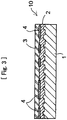
Fig. 3 ] An enlarged cross section of the resin-molded article according to still the other embodiment of the present invention. - [
Fig. 4 ] An enlarged cross section of the resin-molded article according to still the other embodiment of the present invention. - [
Fig. 5 ] A vertical cross section of the apparatus for manufacturing the resin-molded article according to an embodiment of the present invention. - [
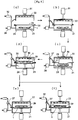
Fig. 6 ] A schematic view showing the former steps of the manufacturing process for the resin-molded article according to an embodiment of the present invention. - [
Fig. 7 ] A schematic view showing the latter steps of the manufacturing process for the resin-molded article according to an embodiment of the present invention. - [
Fig. 8 ] A perspective view showing an example of using the resin-molded article according to the present invention. - [Fir. 9] A perspective view showing the other example of using the resin-molded article according to the present invention.
-
- 1:
- Molded base
- 2:
- Adhering layer
- 3, 29:
- Resin surface skin member (Transparent resin film)
- 4:
- Decorative layer
- 5:
- Etching
- 10:
- Resin-molded article
- 20:
- Manufacturing apparatus for resin-molded articles
- 21:
- Lower chamber box
- 22:
- Upper chamber box
- 23:
- Tray
- 24, 31:
- Driving unit for vertical moving
- 26:
- Vacuum tank
- 27:
- Switching valve
- 28:
- Holding frame
- 30:
- Heater
- 32:
- Pneumatic tank
- 33:
- Cutter
- 41:
- Automotive bumper
- 42:
- Sideview mirror
- 50:
- Golf shaft
- Now, the present invention is explained by means of the examples given below with referring to the appended drawings.
Figs. 1 to 4 show the resin-moldedarticle 10 prepared according to various examples of the present invention.Fig. 1 shows an example of the resin-moldedarticle 10 which is prepared by sticking a resin surface skin film, for example atransparent resin film 3 via the adheringlayer 2 to the upper surface of the moldedarticle 1, which is prepared by mixing a fibrous base material comprising carbon fibers, glass fibers or the complex thereof to a binding agent, followed by molding the mixture. Although the surface of the moldedarticle 1 mixed with the fibrous base material becomes irregular due to the fibrous base material, smooth surface can be attained by sticking theresin film 3 to the irregular surface. Therefore, the moldedarticle 1 can be used for automotive interior and exterior trim parts such as a bumper without applying painting and surface polishing. Note that the molded article prepared by mixing and subsequently molding the fibrous base material and a resin is lightweight and excellent in strength, rigidness and mass-productivity. - As the manner for molding the fibrous base material, though various manners as exemplified below can be employed, it should not be limited to those manners given below. The molding manner includes molding the fibrous base material following to mixing a binding agent as a binder to the fibrous base material, molding after weaving or twisting the fibrous base material, molding by covering the fibrous base member formed by weaving the fibrous material with a binding agent, molding by covering the fibrous base member formed by twisting the fibrous material with a binding agent, molding by forming the fibrous material by employing the above-described manner and apply foundation painting to the surface, and molding by forming the fibrous material by employing the above-described manner and apply foundation painting to the surface and followed by sanding thereof. While, as the resin surface skin film, various types of synthetic resin sheets being capable of sticking to the fibrous base member may be employed. As an example, if acryl material is used for the
transparent resin film 3, the resulted film may be resistant to weather and ultraviolet rays, and the film made of either PC or ABS material may acquire better moldability and productivity. Therefore, the material to be used can be appropriately selected depending on the application. For the adhering layer, an acrylic adhesive is the preferred. The thickness t of the resin surface skin film (transparent resin film 3) containing an adhering layer is preferably in a range of from 0.1 mm to 0.5 mm, however, it is arbitrary determined depending on the application such as place to be used of the molded article. The structures of the moldedarticle 1, the adheringlayer 2 and the resinsurface skin film 3 as explained in the following are same as those described above, respectively. Note that the employable material examples to be used for the resinsurface skin film 3, all materials respectively made of acryl, PC, ABS, PET, vinyl chloride, polyurethane and polypropylene may be given. While, for the binding agent, materials respectively made of ABS, polycarbonate, acryl and nylon are employable. However, the materials being employable for the resin surface skin member is not limited to those described above, any resin sheet that can stick to the molded article in the steps described latter and any material that can be molded with the fibrous material may be employed for the resin surface skin member and the binding agent, respectively. - With regard to the resin-molded
article 10 according to the example shown inFig. 2 , adecorative layer 4 with letters, figures, etc. is formed by means of a printing means to the surface of the moldedarticle 1 from the mixture of a fibrous base material and a resin material, an adheringlayer 2 is attached to the surface of the moldedarticle 1 including thedecorative layer 4, and further atransparent film 3 is stuck to the upper side of the adheringlayer 2. By structuring the adheringlayer 2 with an acryl adhesive, thedecorative layer 4 of the molded article will be visible from the outer side of thetransparent film 3. - With regard to the resin-molded
article 10 according to the example shown inFig. 3 , thetransparent film 3 is stuck to the lower adheringlayer 2 in such a state that the adheringlayer 2 is attached to the upper side of the moldedarticle 1 and thedecorative layer 4 is intervened between theadhesive layer 2 and thetransparent film 3. Similarly to the example shown inFig. 2 , the irregular surface of the moldedarticle 1 is smoothed with thetransparent film 3 and thedecorative layer 4 will be visible from the outer side of thetransparent film 3. - In respect of the resin-molded
article 10 shown inFig. 4 ,etching 5 is applied to the underside of the resin film and the etched underside is stuck to the upper side of the moldedarticle 1 via the adheringlayer 2. By using a transparent film for the resin film and forming the etching in a desired pattern, the etching will be visible as a decorated plane from the outer side of thetransparent film 3. Furthermore, binding with the adheringlayer 2 is further secured by virtue of the etching and the resin-moldedarticle 10 with rigid surface property can be attained. - With referring to
Figs. 5 to 7 , the process and apparatus for manufacturing resin-molded articles according to the present invention will now be explained. Referring toFig. 5 , the apparatus for manufacturing resin-moldedarticles 20 according to an example of the present invention is provided with alower chamber box 21 and anupper chamber box 22 both of those which can be separated relative to the other in the vertical direction. Inside thelower chamber box 21, atray 23 on which the molded base 1 (shown with a virtual line) made of a fibrous material comprising carbon fibers, glass fibers or the complex thereof is placed is arranged in a vertically-movable fashion. Specifically, a vertically-movable driving unit 24 is provided to the underside of thelower chamber box 21, anactuating rod 24a of the drivingunit 24 is inserted into thelower chamber box 21 and a supporting table 25 of thetray 23 is connected to theactuating rod 24a. To thelower chamber box 21, a vacuum suction unit, for example avacuum tank 26 is connected. Thevacuum tank 26 is structured such that it communicates with theupper chamber box 22 via the switchingvalve 27. Yet, afilm holding frame 28 is provided to the upper end of thelower chamber box 21, a resinsurface skin film 29 comprising a resin film (a transparent film) as described inFigs. 1 to 4 , an adhering layer, a decorative layer, etc. is exchangeably attached to the holdingframe 28, and the inside of the boxes are kept in sealed condition in such a state that the resinsurface skin film 29 is attached to the opening located at the upper end of thelower chamber box 21. - Inside the
upper chamber box 22 that ascends and descends relative to thelower chamber box 21, aheater 30 is arranged at the upper position. A vertically-movingdriving unit 31 is provided to the upper position of theupper chamber box 22, and theactuating rod 31a thereof is connected to the upper side of the upper chamber box22. Besides, a pressuring apparatus, e.g. apneumatic tank 32, for rendering the inside of theupper chamber box 22 to be in a pressurized state is connected to saidupper chamber box 22 via the switchingvalve 27. In such a state that theupper chamber box 22 is lowered and closely contacted to thelower chamber box 21 being attached with the resinsurface skin film 29, both insides of the upper andlower chamber boxes - Taking the manufacturing apparatus for the resin-molded articles configured as described above as an example, the process for manufacturing the resin-molded articles according to the present invention will now be explained with referring to
Fig. 6 andFig. 7 . At first, as shown inFig. 6 (a) , theupper chamber box 22 is ascended by the drivingunit 31 to thereby place a target moldedarticle 1, that has been prepared by mixing and subsequent molding of the fibrous base material, on atray 23 provided inside thelower chamber box 21, and at the same time, a desired resinsurface skin film 29 is set to the holdingframe 28 of the resin surface skin film at the upper end of the lower chamber box. At this moment, the inside of thelower chamber box 21 is in a sealed condition. For the resinsurface skin film 29, any one of the surface skin films, the one consisted of a transparent film and an adhering layer, the one consisted of a transparent film, a decorative layer and an adhering layer, and the one consisted of a transparent film, the underside of which being etched, and an adhering layer is selected corresponding to the type and application of the article. Note that the adhering layer of the resinsurface skin film 29 is set downward, namely to the holdingframe 28 so as to face off against the moldedarticle 1 placed on thetray 23. - Then, as shown in
Fig. 6(b) , theupper chamber box 22 is descended by the drivingunit 31 so as to closely contact to thelower chamber box 21, and as shown inFig. 6(c) , by manipulating the switchingvalve 27, the insides of both upper andlower chamber boxes heater 30 is biased to heat the resinsurface skin film 29 in the box to soften the surface skin film. Hanging down of the resinsurface skin film 29 somewhat toward thetray 23 side inFig. 6 (c) indicates that the surface skin film has been softened due to heating with theheater 30. - Then, as shown in
Fig. 6(d) , the moldedarticle 1 on thetray 23 is ascended by the drivingunit 24 and is pressed against the softened resinsurface skin film 29 so that the resinsurface skin film 29 is stuck to the moldedarticle 1. - Subsequently, the inside of the
upper chamber box 22 is shifted from the negative pressurized state to either opened-to-air state or pneumatic state while actuating theheater 30 inside theupper chamber box 22 to thereby accelerate the adhesion of the resinsurface skin film 29 to the surface of the molded article.Fig. 6(e) shows the state that the inside of theupper chamber box 22 is opened to air, andFig. 6 (f) shows the state that the inside of theupper chamber box 22 has been in a pneumatic condition by means of a pneumatic apparatus and thepneumatic tank 32. Although either state may be employed to the manufacturing process, the pneumatic addition configuration as shown inFig. 6(f) must be employed when the objective article requires more strong sticking property. Following thereto, the pneumatic state and the vacuum suction are released as shown inFig. 7(a) and theupper chamber box 22 is ascended to remove the resin-molded article being stuck with thesurface skin film 29 from thetray 23. Since the peripheral portion of the resinsurface skin film 29 protrude slightly from the moldedarticle 1 in this state, the portion of the resinsurface skin film 29 that protrudes from the moldedarticle 1 is cut by trimming with acutter 33 as shown inFig. 7 (b) so that the resin-moldedarticle 10 can be finished. Note that no protrusion of the resin surface skin film from the molded article has been found, trimming work as shown inFig. 7 (b) may be omitted. - The resin-molded article to which surface processing having been applied according to the present invention may be used for various applications because it has advantages of high strength and rigidness, light weight, highly resistant to weather and ultraviolet rays, smoothed surface irregularity and beautiful appearance.
Fig. 8 shows an example of applying the resin-molded article to anautomotive bumper 41 and arear holding member 42a to be used for asideview mirror 42. The resin-molded article according to the present invention can be simply replaced with existing automotive parts and exert performance in the strength, etc., and it can be accepted further for automotive parts as a material capable of exerting sufficient beauty. Moreover, the molded articles according to the present invention can also be applied to automotive interior trims and various automotive parts, such as a dashboard in front of a driver seat and a handle. Yet, the molded articles according to the present invention can further be applied to e.g. fishing poles, golf gear, rackets for ball game, climbing gear, or care tools such as sticks, powered suits and walking training equipments.Fig. 9 is an example to apply the resin-moldedarticles 10 according to the present invention to agolf shaft 50, and it is possible to provide a golf shaft that can satisfy various performance having been required by the existing golf shafts and is superior in the beautiful appearance. The application of the resin-moldedarticles 10 according to the present invention is not limited to the two examples described above and is applicable to various daily commodity and structural parts over the wide-range. - According to the present invention, an resin-molded article having excellent surface property, such as surface smoothness and beautiful appearance, while securing advantages of strength, rigidness and lightweight given by virtue of kneading of fibers, and further being provided with resistance against weather, ultraviolet rays and light can be attained. In addition, a process and an apparatus for manufacturing resin-molded articles, which enables easy surface processing to the surface of a molded article comprising a fibrous base member, reduction of the manufacturing steps and homogenization of the surface aspect, such as smoothening of surface, can also attained.
Claims (15)
- A resin-molded article prepared by sticking a resin surface skin material provide with an adhering layer to a molded fibrous base member comprising any of carbon fibers, glass fibers and the complex thereof.
- A resin-molded article according to Claim 1, characterized in that the molded article is prepared by adding at least one material selected from a group consisting of ABS, polycarbonate, acryl and nylon as a binding agent to the fibrous base member and performing the following molding.
- A resin-molded article according to Claim 1 or Claim 2, characterized in that the resin surface skin member is so structured that an adhering layer is attached to the underside of a resin film and a decorative layer is formed on the surface of the molded fibrous base.
- A resin-molded article according to any one of Claims 1 to 3, characterized in that the resin surface skin member is so structured that an adhering layer is attached to the underside of a resin film and a decorative layer is intervened between the resin film and the adhering layer.
- A resin-molded article according to any one of Claims 1 to 4, characterized in that the resin surface skin member is prepared by etching the underside of the resin film and then attaching an adhering layer to the underside.
- A resin-molded article according to any one of Claims 1 to 5, characterized in that the resin surface skin member comprises at least one material selected from a group consisting of acryl, polycarbonate, ABS, PET, vinyl chloride, polyurethane and polypropylene.
- A resin-molded article according to any one of Claims 1 to 6, characterized in that the thickness of the resin surface skin member is in a range of from 0.1 mm to 0.5 mm.
- A process for manufacturing resin-molded articles, characterized in that the process comprises the following steps:placing a molded base made of a fibrous base material comprising any of carbon fibers, glass fibers and the complex thereof on a tray,arranging the resin surface skin member provided with an adhering layer over the molded base such that the adhering layer of the resin surface skin member is directed downward,rendering the surroundings of the molded base and the resin surface skin member in a negatively-pressurized state and heating the resin surface skin member,heating the resin surface skin member and ascending the tray to thereby closely contact the molded base to the resin surface skin member, andrendering the upper region of the tray in a pressurized state and subsequently opening the surrounding of the tray to remove the molded base coated with the resin surface skin member.
- A process for manufacturing resin-molded articles according to Claim 8, characterized in that the resin surface skin member is so structured that an adhering layer is attached to the underside of a resin film and a decorative layer is formed on the surface of the molded fibrous base.
- A process for manufacturing resin-molded articles according to Claim 8 or Claim 9, characterized in that the resin surface skin member is so structured that an adhering layer is attached to the underside of a resin film and a decorative layer is intervened between the resin film and the adhering layer.
- A process for manufacturing resin-molded articles according to any one of Claims 8 to 10, characterized in that the resin surface skin member is prepared by etching the underside of the resin film and then attaching an adhering layer to the underside.
- A process for manufacturing resin-molded articles according to any one of Claims 8 to 11, characterized in that the resin surface skin member comprises at least one material selected from a group consisting of acryl, polycarbonate, ABS, PET, vinyl chloride, polyurethane and polypropylene.
- A process for manufacturing resin-molded articles according to any one of Claims 8 to 12, characterized in that the thickness of the resin surface skin member is in a range of from 0.1 mm to 0.5 mm.
- A process for manufacturing resin-molded articles according to any one of Claims 8 to 13, characterized in that the molded article is prepared by adding at least one material selected from a group consisting of ABS, polycarbonate, acryl and nylon as a binding agent to the fibrous base member and performing the following molding.
- An apparatus for manufacturing resin-molded articles comprising:a lower chamber box movably holding a tray for the molded fibrous base in the vertical direction,an upper chamber box having a heater built-in and movable in the vertical direction relative to the lower chamber box,a resin surface skin member extended over the area locating between the upper and lower chamber boxes,a negative pressure biasing means arranged in both of the upper and lower chamber boxes and communicating them,a pneumatic biasing means communicated with the upper chamber box,a driving unit for moving the tray in the vertical direction, anda driving unit for moving the upper chamber box in the vertical direction,characterized in that the apparatus is configured such that the resin surface skin member is coated to the molded base by virtue of press given by the molded base on the tray against the resin surface skin member owing to the elevation of the lower chamber box, or application and release of bias generated by the negative pressure biasing means and the pneumatic biasing means, or heating by the heater.
Applications Claiming Priority (2)
| Application Number | Priority Date | Filing Date | Title |
|---|---|---|---|
| JP2015197001A JP6462547B2 (en) | 2015-10-02 | 2015-10-02 | Resin molded product and method for producing resin molded product |
| PCT/JP2016/071499 WO2017056655A1 (en) | 2015-10-02 | 2016-07-22 | Resin molded article, method for manufacturing resin molded article, and device for manufacturing resin molded article |
Publications (3)
| Publication Number | Publication Date |
|---|---|
| EP3357688A1 true EP3357688A1 (en) | 2018-08-08 |
| EP3357688A4 EP3357688A4 (en) | 2019-05-08 |
| EP3357688B1 EP3357688B1 (en) | 2022-06-08 |
Family
ID=58423429
Family Applications (1)
| Application Number | Title | Priority Date | Filing Date |
|---|---|---|---|
| EP16850832.3A Not-in-force EP3357688B1 (en) | 2015-10-02 | 2016-07-22 | Resin molded article, method for manufacturing resin molded article |
Country Status (8)
| Country | Link |
|---|---|
| US (2) | US20170334146A1 (en) |
| EP (1) | EP3357688B1 (en) |
| JP (1) | JP6462547B2 (en) |
| KR (1) | KR102030637B1 (en) |
| CN (1) | CN106817896A (en) |
| MX (1) | MX2016014757A (en) |
| TW (1) | TWI690549B (en) |
| WO (1) | WO2017056655A1 (en) |
Families Citing this family (8)
| Publication number | Priority date | Publication date | Assignee | Title |
|---|---|---|---|---|
| EP3551502B1 (en) * | 2016-12-08 | 2021-07-21 | Autoneum Management AG | Surface coating for an exterior trim part |
| KR102343968B1 (en) * | 2017-12-15 | 2021-12-28 | 주식회사 쿠라레 | Decorated molded body, manufacturing method thereof, and light-emitting structure using the decorative molded body |
| EP3778195B1 (en) * | 2018-03-30 | 2023-07-12 | Toray Industries, Inc. | Method for manufacturing molded article |
| CN109094000A (en) * | 2018-09-10 | 2018-12-28 | 温州祺旺科技有限公司 | A kind of pair of three-dimensional objects surface band the process of overlay film |
| EP3747639A1 (en) | 2019-06-07 | 2020-12-09 | Siemens Gamesa Renewable Energy A/S | Method for manufacturing a wind turbine blade and wind turbine blade |
| KR102720703B1 (en) * | 2019-07-29 | 2024-10-22 | 주식회사 엘지화학 | Exterior materials for automobiles and preparation method thereof |
| DE102019215945A1 (en) | 2019-10-16 | 2021-04-22 | Joyson Safety Systems Germany Gmbh | Device and method for the material connection of at least one material segment with a steering device |
| KR20240060056A (en) * | 2022-10-28 | 2024-05-08 | 주식회사 엘지화학 | Molded body |
Family Cites Families (20)
| Publication number | Priority date | Publication date | Assignee | Title |
|---|---|---|---|---|
| JPH05116211A (en) * | 1991-10-24 | 1993-05-14 | Nitto Boseki Co Ltd | Formation of fiber reinforced resin molded body laminated with metallic foil |
| JP3230838B2 (en) | 1992-04-15 | 2001-11-19 | 新日鐵化学株式会社 | Auto bodies and parts |
| US5472771A (en) * | 1993-12-30 | 1995-12-05 | Barrett Boating Canvas & Upholstery, Inc. | Method for adhering a flexible fibrous sheet to a semi-rigid thermoplastic resinous sheet and products relating thereto |
| JP3570580B2 (en) * | 1995-07-27 | 2004-09-29 | Jfeケミカル株式会社 | Method for producing fiber-reinforced thermoplastic resin molded article |
| JPH11106518A (en) | 1997-10-01 | 1999-04-20 | Mitsubishi Motors Corp | Automotive exterior parts |
| JP3733564B2 (en) * | 2000-09-04 | 2006-01-11 | 布施真空株式会社 | Vacuum forming equipment |
| JP4082218B2 (en) * | 2003-01-08 | 2008-04-30 | トヨタ紡織株式会社 | Automotive interior materials |
| US20040253428A1 (en) * | 2003-06-12 | 2004-12-16 | General Electric Company | Weatherable multilayer articles and method for their preparation |
| JP3924761B2 (en) * | 2004-06-22 | 2007-06-06 | 布施真空株式会社 | Method and apparatus for coating hollow core material |
| US20070231576A1 (en) * | 2005-09-30 | 2007-10-04 | Davis M S | Multilayer films comprising tie layer compositions, articles prepared therefrom, and method of making |
| WO2010083534A1 (en) * | 2009-01-19 | 2010-07-22 | Avery Dennison Corporation | Durable in-mold decoration laminates using semi-crystalline polymer as top film |
| WO2011114484A1 (en) * | 2010-03-18 | 2011-09-22 | トヨタ自動車株式会社 | Resin film coating method and coating device |
| JP2012096416A (en) | 2010-10-31 | 2012-05-24 | Fuse Shinku Kk | Vacuum molding machine, substrate for vacuum molding machine, and vacuum molding method |
| JP5549036B2 (en) | 2010-11-30 | 2014-07-16 | 布施真空株式会社 | Vacuum forming method |
| JP2012200681A (en) | 2011-03-25 | 2012-10-22 | Kansai Paint Co Ltd | Coating film forming method and coated article |
| JP2012223904A (en) * | 2011-04-15 | 2012-11-15 | Nitto Denko Corp | Transparent resin film with pressure-sensitive adhesive layer, laminated film, and touch panel |
| JP5942383B2 (en) * | 2011-07-29 | 2016-06-29 | 豊國工業株式会社 | Storage with door with buffer function |
| WO2013022027A1 (en) | 2011-08-08 | 2013-02-14 | 布施真空株式会社 | Vehicle functional component |
| JP5604569B1 (en) | 2013-08-05 | 2014-10-08 | 布施真空株式会社 | Partial vacuum forming method by partial overlay of decorative film |
| JP6163971B2 (en) * | 2013-08-27 | 2017-07-19 | 王子ホールディングス株式会社 | Decorative molded product and method for producing decorative molded product |
-
2015
- 2015-10-02 JP JP2015197001A patent/JP6462547B2/en active Active
-
2016
- 2016-07-22 CN CN201680002253.XA patent/CN106817896A/en active Pending
- 2016-07-22 KR KR1020167032027A patent/KR102030637B1/en not_active Expired - Fee Related
- 2016-07-22 US US15/525,611 patent/US20170334146A1/en not_active Abandoned
- 2016-07-22 WO PCT/JP2016/071499 patent/WO2017056655A1/en not_active Ceased
- 2016-07-22 MX MX2016014757A patent/MX2016014757A/en unknown
- 2016-07-22 EP EP16850832.3A patent/EP3357688B1/en not_active Not-in-force
- 2016-09-30 TW TW105131467A patent/TWI690549B/en not_active IP Right Cessation
-
2020
- 2020-01-21 US US16/747,770 patent/US20200156327A1/en not_active Abandoned
Also Published As
| Publication number | Publication date |
|---|---|
| JP2017065230A (en) | 2017-04-06 |
| KR20180018252A (en) | 2018-02-21 |
| TW201730249A (en) | 2017-09-01 |
| TWI690549B (en) | 2020-04-11 |
| MX2016014757A (en) | 2017-05-30 |
| CN106817896A (en) | 2017-06-09 |
| KR102030637B1 (en) | 2019-10-10 |
| US20170334146A1 (en) | 2017-11-23 |
| EP3357688B1 (en) | 2022-06-08 |
| JP6462547B2 (en) | 2019-01-30 |
| WO2017056655A1 (en) | 2017-04-06 |
| US20200156327A1 (en) | 2020-05-21 |
| EP3357688A4 (en) | 2019-05-08 |
Similar Documents
| Publication | Publication Date | Title |
|---|---|---|
| US20200156327A1 (en) | Resin-molded articles, and a process and an apparatus for manufacturing the same | |
| KR20190007003A (en) | Plastic Vehicle Additional Parts Manufacturing Method | |
| CN110435074B (en) | Method for producing molded article containing solid wood | |
| EP2545802B1 (en) | Manufacturing method of artificial nail with 3-dimension ornament | |
| CN109878186A (en) | A kind of fiber decorating film and preparation method thereof and product | |
| US20090047854A1 (en) | Method of manufacturing a product part by using a composite fibre sheet and applying plastic to this sheet | |
| WO1993021014A1 (en) | Direct-to-helmet vacuum forming process for helmet decorating | |
| US5916843A (en) | Picture with integrated picture frame | |
| CN109435864A (en) | A kind of truewood lighting decoration and its manufacturing method | |
| JP2001138468A (en) | Decorative sheet and method of decorating molded article using the same | |
| CN101348023A (en) | Method and device for attaching back adhesive skin | |
| KR102199267B1 (en) | Resin impregnated sheet and Insert injection molding method using the same | |
| US20070026201A1 (en) | Molded articles and methods of producing them | |
| US7575651B2 (en) | Method for applying web material to a molded plastic object | |
| JP2020175555A (en) | Resin-decorated article and convex decoration processing method on the surface of the article | |
| KR20170004927A (en) | Silicone molding members | |
| KR102160771B1 (en) | Real wood product and manufacturing method thereof | |
| JP2001098479A (en) | Decorative fabric using resin and method of manufacturing the same | |
| JP3194242U (en) | Painting | |
| KR101643933B1 (en) | Coating method of the resin sheet and the coating apparatus using the same | |
| TWI304961B (en) | Label visible as 3d and to be attached on a plastic product in a mold | |
| JP2001145579A (en) | Acrylic resin bathtub | |
| JP2003170403A (en) | Decorative article and manufacturing method thereof | |
| JP4850778B2 (en) | Decorative sheets, molded articles and transport equipment | |
| CN118664917A (en) | Glasses decoration manufacturing method and processing equipment thereof |
Legal Events
| Date | Code | Title | Description |
|---|---|---|---|
| STAA | Information on the status of an ep patent application or granted ep patent |
Free format text: STATUS: THE INTERNATIONAL PUBLICATION HAS BEEN MADE |
|
| PUAI | Public reference made under article 153(3) epc to a published international application that has entered the european phase |
Free format text: ORIGINAL CODE: 0009012 |
|
| STAA | Information on the status of an ep patent application or granted ep patent |
Free format text: STATUS: REQUEST FOR EXAMINATION WAS MADE |
|
| 17P | Request for examination filed |
Effective date: 20170517 |
|
| AK | Designated contracting states |
Kind code of ref document: A1 Designated state(s): AL AT BE BG CH CY CZ DE DK EE ES FI FR GB GR HR HU IE IS IT LI LT LU LV MC MK MT NL NO PL PT RO RS SE SI SK SM TR |
|
| AX | Request for extension of the european patent |
Extension state: BA ME |
|
| DAV | Request for validation of the european patent (deleted) | ||
| DAX | Request for extension of the european patent (deleted) | ||
| A4 | Supplementary search report drawn up and despatched |
Effective date: 20190410 |
|
| RIC1 | Information provided on ipc code assigned before grant |
Ipc: B32B 27/16 20060101ALN20190404BHEP Ipc: B32B 7/12 20060101ALI20190404BHEP Ipc: C08J 5/04 20060101ALI20190404BHEP Ipc: B29C 51/12 20060101ALN20190404BHEP Ipc: B29C 65/40 20060101ALI20190404BHEP Ipc: B29C 51/26 20060101ALN20190404BHEP Ipc: B29K 105/06 20060101ALN20190404BHEP Ipc: B29C 63/02 20060101ALN20190404BHEP Ipc: B29L 31/30 20060101ALN20190404BHEP Ipc: B32B 3/30 20060101ALN20190404BHEP Ipc: B29C 51/10 20060101ALI20190404BHEP Ipc: B29C 51/08 20060101AFI20190404BHEP Ipc: B32B 5/02 20060101ALI20190404BHEP Ipc: B29L 31/52 20060101ALN20190404BHEP Ipc: B32B 27/12 20060101ALI20190404BHEP Ipc: B29C 51/16 20060101ALN20190404BHEP |
|
| STAA | Information on the status of an ep patent application or granted ep patent |
Free format text: STATUS: EXAMINATION IS IN PROGRESS |
|
| 17Q | First examination report despatched |
Effective date: 20200221 |
|
| REG | Reference to a national code |
Ref country code: DE Ref legal event code: R079 Ref document number: 602016072756 Country of ref document: DE Free format text: PREVIOUS MAIN CLASS: B32B0027120000 Ipc: B29C0051080000 |
|
| GRAP | Despatch of communication of intention to grant a patent |
Free format text: ORIGINAL CODE: EPIDOSNIGR1 |
|
| STAA | Information on the status of an ep patent application or granted ep patent |
Free format text: STATUS: GRANT OF PATENT IS INTENDED |
|
| RIC1 | Information provided on ipc code assigned before grant |
Ipc: B29K 105/00 20060101ALN20211209BHEP Ipc: B29C 51/46 20060101ALN20211209BHEP Ipc: B29C 51/14 20060101ALN20211209BHEP Ipc: B29C 51/04 20060101ALN20211209BHEP Ipc: B32B 27/16 20060101ALN20211209BHEP Ipc: B32B 3/30 20060101ALN20211209BHEP Ipc: B29L 31/30 20060101ALN20211209BHEP Ipc: B29C 51/26 20060101ALN20211209BHEP Ipc: B29C 51/16 20060101ALN20211209BHEP Ipc: B29C 51/12 20060101ALN20211209BHEP Ipc: B29K 105/06 20060101ALN20211209BHEP Ipc: B29L 31/52 20060101ALN20211209BHEP Ipc: B29C 63/02 20060101ALN20211209BHEP Ipc: B32B 27/40 20060101ALI20211209BHEP Ipc: B32B 27/36 20060101ALI20211209BHEP Ipc: B32B 27/32 20060101ALI20211209BHEP Ipc: B32B 27/30 20060101ALI20211209BHEP Ipc: B32B 7/12 20060101ALI20211209BHEP Ipc: C08J 5/04 20060101ALI20211209BHEP Ipc: B32B 5/02 20060101ALI20211209BHEP Ipc: B29C 65/40 20060101ALI20211209BHEP Ipc: B32B 27/12 20060101ALI20211209BHEP Ipc: B29C 51/10 20060101ALI20211209BHEP Ipc: B29C 51/08 20060101AFI20211209BHEP |
|
| RIC1 | Information provided on ipc code assigned before grant |
Ipc: B29K 105/00 20060101ALN20211213BHEP Ipc: B29C 51/46 20060101ALN20211213BHEP Ipc: B29C 51/14 20060101ALN20211213BHEP Ipc: B29C 51/04 20060101ALN20211213BHEP Ipc: B32B 27/16 20060101ALN20211213BHEP Ipc: B32B 3/30 20060101ALN20211213BHEP Ipc: B29L 31/30 20060101ALN20211213BHEP Ipc: B29C 51/26 20060101ALN20211213BHEP Ipc: B29C 51/16 20060101ALN20211213BHEP Ipc: B29C 51/12 20060101ALN20211213BHEP Ipc: B29K 105/06 20060101ALN20211213BHEP Ipc: B29L 31/52 20060101ALN20211213BHEP Ipc: B29C 63/02 20060101ALN20211213BHEP Ipc: B32B 27/40 20060101ALI20211213BHEP Ipc: B32B 27/36 20060101ALI20211213BHEP Ipc: B32B 27/32 20060101ALI20211213BHEP Ipc: B32B 27/30 20060101ALI20211213BHEP Ipc: B32B 7/12 20060101ALI20211213BHEP Ipc: C08J 5/04 20060101ALI20211213BHEP Ipc: B32B 5/02 20060101ALI20211213BHEP Ipc: B29C 65/40 20060101ALI20211213BHEP Ipc: B32B 27/12 20060101ALI20211213BHEP Ipc: B29C 51/10 20060101ALI20211213BHEP Ipc: B29C 51/08 20060101AFI20211213BHEP |
|
| INTG | Intention to grant announced |
Effective date: 20220104 |
|
| GRAS | Grant fee paid |
Free format text: ORIGINAL CODE: EPIDOSNIGR3 |
|
| GRAA | (expected) grant |
Free format text: ORIGINAL CODE: 0009210 |
|
| STAA | Information on the status of an ep patent application or granted ep patent |
Free format text: STATUS: THE PATENT HAS BEEN GRANTED |
|
| AK | Designated contracting states |
Kind code of ref document: B1 Designated state(s): AL AT BE BG CH CY CZ DE DK EE ES FI FR GB GR HR HU IE IS IT LI LT LU LV MC MK MT NL NO PL PT RO RS SE SI SK SM TR |
|
| REG | Reference to a national code |
Ref country code: GB Ref legal event code: FG4D |
|
| REG | Reference to a national code |
Ref country code: AT Ref legal event code: REF Ref document number: 1496631 Country of ref document: AT Kind code of ref document: T Effective date: 20220615 Ref country code: CH Ref legal event code: EP |
|
| REG | Reference to a national code |
Ref country code: DE Ref legal event code: R096 Ref document number: 602016072756 Country of ref document: DE |
|
| REG | Reference to a national code |
Ref country code: IE Ref legal event code: FG4D |
|
| REG | Reference to a national code |
Ref country code: LT Ref legal event code: MG9D |
|
| REG | Reference to a national code |
Ref country code: NL Ref legal event code: MP Effective date: 20220608 |
|
| PG25 | Lapsed in a contracting state [announced via postgrant information from national office to epo] |
Ref country code: SE Free format text: LAPSE BECAUSE OF FAILURE TO SUBMIT A TRANSLATION OF THE DESCRIPTION OR TO PAY THE FEE WITHIN THE PRESCRIBED TIME-LIMIT Effective date: 20220608 Ref country code: NO Free format text: LAPSE BECAUSE OF FAILURE TO SUBMIT A TRANSLATION OF THE DESCRIPTION OR TO PAY THE FEE WITHIN THE PRESCRIBED TIME-LIMIT Effective date: 20220908 Ref country code: LT Free format text: LAPSE BECAUSE OF FAILURE TO SUBMIT A TRANSLATION OF THE DESCRIPTION OR TO PAY THE FEE WITHIN THE PRESCRIBED TIME-LIMIT Effective date: 20220608 Ref country code: HR Free format text: LAPSE BECAUSE OF FAILURE TO SUBMIT A TRANSLATION OF THE DESCRIPTION OR TO PAY THE FEE WITHIN THE PRESCRIBED TIME-LIMIT Effective date: 20220608 Ref country code: GR Free format text: LAPSE BECAUSE OF FAILURE TO SUBMIT A TRANSLATION OF THE DESCRIPTION OR TO PAY THE FEE WITHIN THE PRESCRIBED TIME-LIMIT Effective date: 20220909 Ref country code: FI Free format text: LAPSE BECAUSE OF FAILURE TO SUBMIT A TRANSLATION OF THE DESCRIPTION OR TO PAY THE FEE WITHIN THE PRESCRIBED TIME-LIMIT Effective date: 20220608 Ref country code: ES Free format text: LAPSE BECAUSE OF FAILURE TO SUBMIT A TRANSLATION OF THE DESCRIPTION OR TO PAY THE FEE WITHIN THE PRESCRIBED TIME-LIMIT Effective date: 20220608 Ref country code: BG Free format text: LAPSE BECAUSE OF FAILURE TO SUBMIT A TRANSLATION OF THE DESCRIPTION OR TO PAY THE FEE WITHIN THE PRESCRIBED TIME-LIMIT Effective date: 20220908 |
|
| REG | Reference to a national code |
Ref country code: AT Ref legal event code: MK05 Ref document number: 1496631 Country of ref document: AT Kind code of ref document: T Effective date: 20220608 |
|
| PG25 | Lapsed in a contracting state [announced via postgrant information from national office to epo] |
Ref country code: RS Free format text: LAPSE BECAUSE OF FAILURE TO SUBMIT A TRANSLATION OF THE DESCRIPTION OR TO PAY THE FEE WITHIN THE PRESCRIBED TIME-LIMIT Effective date: 20220608 Ref country code: LV Free format text: LAPSE BECAUSE OF FAILURE TO SUBMIT A TRANSLATION OF THE DESCRIPTION OR TO PAY THE FEE WITHIN THE PRESCRIBED TIME-LIMIT Effective date: 20220608 |
|
| PG25 | Lapsed in a contracting state [announced via postgrant information from national office to epo] |
Ref country code: NL Free format text: LAPSE BECAUSE OF FAILURE TO SUBMIT A TRANSLATION OF THE DESCRIPTION OR TO PAY THE FEE WITHIN THE PRESCRIBED TIME-LIMIT Effective date: 20220608 |
|
| PG25 | Lapsed in a contracting state [announced via postgrant information from national office to epo] |
Ref country code: SM Free format text: LAPSE BECAUSE OF FAILURE TO SUBMIT A TRANSLATION OF THE DESCRIPTION OR TO PAY THE FEE WITHIN THE PRESCRIBED TIME-LIMIT Effective date: 20220608 Ref country code: SK Free format text: LAPSE BECAUSE OF FAILURE TO SUBMIT A TRANSLATION OF THE DESCRIPTION OR TO PAY THE FEE WITHIN THE PRESCRIBED TIME-LIMIT Effective date: 20220608 Ref country code: RO Free format text: LAPSE BECAUSE OF FAILURE TO SUBMIT A TRANSLATION OF THE DESCRIPTION OR TO PAY THE FEE WITHIN THE PRESCRIBED TIME-LIMIT Effective date: 20220608 Ref country code: PT Free format text: LAPSE BECAUSE OF FAILURE TO SUBMIT A TRANSLATION OF THE DESCRIPTION OR TO PAY THE FEE WITHIN THE PRESCRIBED TIME-LIMIT Effective date: 20221010 Ref country code: EE Free format text: LAPSE BECAUSE OF FAILURE TO SUBMIT A TRANSLATION OF THE DESCRIPTION OR TO PAY THE FEE WITHIN THE PRESCRIBED TIME-LIMIT Effective date: 20220608 Ref country code: CZ Free format text: LAPSE BECAUSE OF FAILURE TO SUBMIT A TRANSLATION OF THE DESCRIPTION OR TO PAY THE FEE WITHIN THE PRESCRIBED TIME-LIMIT Effective date: 20220608 Ref country code: AT Free format text: LAPSE BECAUSE OF FAILURE TO SUBMIT A TRANSLATION OF THE DESCRIPTION OR TO PAY THE FEE WITHIN THE PRESCRIBED TIME-LIMIT Effective date: 20220608 |
|
| PG25 | Lapsed in a contracting state [announced via postgrant information from national office to epo] |
Ref country code: PL Free format text: LAPSE BECAUSE OF FAILURE TO SUBMIT A TRANSLATION OF THE DESCRIPTION OR TO PAY THE FEE WITHIN THE PRESCRIBED TIME-LIMIT Effective date: 20220608 Ref country code: IS Free format text: LAPSE BECAUSE OF FAILURE TO SUBMIT A TRANSLATION OF THE DESCRIPTION OR TO PAY THE FEE WITHIN THE PRESCRIBED TIME-LIMIT Effective date: 20221008 |
|
| REG | Reference to a national code |
Ref country code: CH Ref legal event code: PL |
|
| REG | Reference to a national code |
Ref country code: DE Ref legal event code: R097 Ref document number: 602016072756 Country of ref document: DE |
|
| REG | Reference to a national code |
Ref country code: BE Ref legal event code: MM Effective date: 20220731 |
|
| PG25 | Lapsed in a contracting state [announced via postgrant information from national office to epo] |
Ref country code: MC Free format text: LAPSE BECAUSE OF FAILURE TO SUBMIT A TRANSLATION OF THE DESCRIPTION OR TO PAY THE FEE WITHIN THE PRESCRIBED TIME-LIMIT Effective date: 20220608 Ref country code: AL Free format text: LAPSE BECAUSE OF FAILURE TO SUBMIT A TRANSLATION OF THE DESCRIPTION OR TO PAY THE FEE WITHIN THE PRESCRIBED TIME-LIMIT Effective date: 20220608 |
|
| PLBE | No opposition filed within time limit |
Free format text: ORIGINAL CODE: 0009261 |
|
| STAA | Information on the status of an ep patent application or granted ep patent |
Free format text: STATUS: NO OPPOSITION FILED WITHIN TIME LIMIT |
|
| PG25 | Lapsed in a contracting state [announced via postgrant information from national office to epo] |
Ref country code: LU Free format text: LAPSE BECAUSE OF NON-PAYMENT OF DUE FEES Effective date: 20220722 Ref country code: LI Free format text: LAPSE BECAUSE OF NON-PAYMENT OF DUE FEES Effective date: 20220731 Ref country code: DK Free format text: LAPSE BECAUSE OF FAILURE TO SUBMIT A TRANSLATION OF THE DESCRIPTION OR TO PAY THE FEE WITHIN THE PRESCRIBED TIME-LIMIT Effective date: 20220608 Ref country code: CH Free format text: LAPSE BECAUSE OF NON-PAYMENT OF DUE FEES Effective date: 20220731 |
|
| 26N | No opposition filed |
Effective date: 20230310 |
|
| GBPC | Gb: european patent ceased through non-payment of renewal fee |
Effective date: 20220908 |
|
| PG25 | Lapsed in a contracting state [announced via postgrant information from national office to epo] |
Ref country code: SI Free format text: LAPSE BECAUSE OF FAILURE TO SUBMIT A TRANSLATION OF THE DESCRIPTION OR TO PAY THE FEE WITHIN THE PRESCRIBED TIME-LIMIT Effective date: 20220608 Ref country code: BE Free format text: LAPSE BECAUSE OF NON-PAYMENT OF DUE FEES Effective date: 20220731 |
|
| PG25 | Lapsed in a contracting state [announced via postgrant information from national office to epo] |
Ref country code: IE Free format text: LAPSE BECAUSE OF NON-PAYMENT OF DUE FEES Effective date: 20220722 |
|
| PG25 | Lapsed in a contracting state [announced via postgrant information from national office to epo] |
Ref country code: GB Free format text: LAPSE BECAUSE OF NON-PAYMENT OF DUE FEES Effective date: 20220908 |
|
| PGFP | Annual fee paid to national office [announced via postgrant information from national office to epo] |
Ref country code: IT Payment date: 20230724 Year of fee payment: 8 |
|
| PGFP | Annual fee paid to national office [announced via postgrant information from national office to epo] |
Ref country code: FR Payment date: 20230726 Year of fee payment: 8 Ref country code: DE Payment date: 20230616 Year of fee payment: 8 |
|
| PG25 | Lapsed in a contracting state [announced via postgrant information from national office to epo] |
Ref country code: HU Free format text: LAPSE BECAUSE OF FAILURE TO SUBMIT A TRANSLATION OF THE DESCRIPTION OR TO PAY THE FEE WITHIN THE PRESCRIBED TIME-LIMIT; INVALID AB INITIO Effective date: 20160722 |
|
| PG25 | Lapsed in a contracting state [announced via postgrant information from national office to epo] |
Ref country code: MK Free format text: LAPSE BECAUSE OF FAILURE TO SUBMIT A TRANSLATION OF THE DESCRIPTION OR TO PAY THE FEE WITHIN THE PRESCRIBED TIME-LIMIT Effective date: 20220608 Ref country code: CY Free format text: LAPSE BECAUSE OF FAILURE TO SUBMIT A TRANSLATION OF THE DESCRIPTION OR TO PAY THE FEE WITHIN THE PRESCRIBED TIME-LIMIT Effective date: 20220608 |
|
| PG25 | Lapsed in a contracting state [announced via postgrant information from national office to epo] |
Ref country code: MT Free format text: LAPSE BECAUSE OF FAILURE TO SUBMIT A TRANSLATION OF THE DESCRIPTION OR TO PAY THE FEE WITHIN THE PRESCRIBED TIME-LIMIT Effective date: 20220608 |
|
| PG25 | Lapsed in a contracting state [announced via postgrant information from national office to epo] |
Ref country code: BG Free format text: LAPSE BECAUSE OF FAILURE TO SUBMIT A TRANSLATION OF THE DESCRIPTION OR TO PAY THE FEE WITHIN THE PRESCRIBED TIME-LIMIT Effective date: 20220608 |
|
| PG25 | Lapsed in a contracting state [announced via postgrant information from national office to epo] |
Ref country code: BG Free format text: LAPSE BECAUSE OF FAILURE TO SUBMIT A TRANSLATION OF THE DESCRIPTION OR TO PAY THE FEE WITHIN THE PRESCRIBED TIME-LIMIT Effective date: 20220608 |
|
| REG | Reference to a national code |
Ref country code: DE Ref legal event code: R119 Ref document number: 602016072756 Country of ref document: DE |
|
| PG25 | Lapsed in a contracting state [announced via postgrant information from national office to epo] |
Ref country code: DE Free format text: LAPSE BECAUSE OF NON-PAYMENT OF DUE FEES Effective date: 20250201 |
|
| PG25 | Lapsed in a contracting state [announced via postgrant information from national office to epo] |
Ref country code: FR Free format text: LAPSE BECAUSE OF NON-PAYMENT OF DUE FEES Effective date: 20240731 |
|
| PG25 | Lapsed in a contracting state [announced via postgrant information from national office to epo] |
Ref country code: IT Free format text: LAPSE BECAUSE OF NON-PAYMENT OF DUE FEES Effective date: 20240722 |
|
| PG25 | Lapsed in a contracting state [announced via postgrant information from national office to epo] |
Ref country code: TR Free format text: LAPSE BECAUSE OF FAILURE TO SUBMIT A TRANSLATION OF THE DESCRIPTION OR TO PAY THE FEE WITHIN THE PRESCRIBED TIME-LIMIT Effective date: 20220608 |