EP3357621A1 - Spherical articulating fixture - Google Patents
Spherical articulating fixture Download PDFInfo
- Publication number
- EP3357621A1 EP3357621A1 EP18153165.8A EP18153165A EP3357621A1 EP 3357621 A1 EP3357621 A1 EP 3357621A1 EP 18153165 A EP18153165 A EP 18153165A EP 3357621 A1 EP3357621 A1 EP 3357621A1
- Authority
- EP
- European Patent Office
- Prior art keywords
- clamp
- fixture
- component
- sphere
- rim
- Prior art date
- Legal status (The legal status is an assumption and is not a legal conclusion. Google has not performed a legal analysis and makes no representation as to the accuracy of the status listed.)
- Granted
Links
Images



Classifications
-
- B—PERFORMING OPERATIONS; TRANSPORTING
- B23—MACHINE TOOLS; METAL-WORKING NOT OTHERWISE PROVIDED FOR
- B23K—SOLDERING OR UNSOLDERING; WELDING; CLADDING OR PLATING BY SOLDERING OR WELDING; CUTTING BY APPLYING HEAT LOCALLY, e.g. FLAME CUTTING; WORKING BY LASER BEAM
- B23K3/00—Tools, devices or special appurtenances for soldering, e.g. brazing, or unsoldering, not specially adapted for particular methods
- B23K3/08—Auxiliary devices therefor
- B23K3/087—Soldering or brazing jigs, fixtures or clamping means
-
- B—PERFORMING OPERATIONS; TRANSPORTING
- B05—SPRAYING OR ATOMISING IN GENERAL; APPLYING FLUENT MATERIALS TO SURFACES, IN GENERAL
- B05C—APPARATUS FOR APPLYING FLUENT MATERIALS TO SURFACES, IN GENERAL
- B05C13/00—Means for manipulating or holding work, e.g. for separate articles
-
- B—PERFORMING OPERATIONS; TRANSPORTING
- B05—SPRAYING OR ATOMISING IN GENERAL; APPLYING FLUENT MATERIALS TO SURFACES, IN GENERAL
- B05D—PROCESSES FOR APPLYING FLUENT MATERIALS TO SURFACES, IN GENERAL
- B05D1/00—Processes for applying liquids or other fluent materials
-
- B—PERFORMING OPERATIONS; TRANSPORTING
- B23—MACHINE TOOLS; METAL-WORKING NOT OTHERWISE PROVIDED FOR
- B23K—SOLDERING OR UNSOLDERING; WELDING; CLADDING OR PLATING BY SOLDERING OR WELDING; CUTTING BY APPLYING HEAT LOCALLY, e.g. FLAME CUTTING; WORKING BY LASER BEAM
- B23K1/00—Soldering, e.g. brazing, or unsoldering
- B23K1/0008—Soldering, e.g. brazing, or unsoldering specially adapted for particular articles or work
- B23K1/0018—Brazing of turbine parts
-
- B—PERFORMING OPERATIONS; TRANSPORTING
- B23—MACHINE TOOLS; METAL-WORKING NOT OTHERWISE PROVIDED FOR
- B23K—SOLDERING OR UNSOLDERING; WELDING; CLADDING OR PLATING BY SOLDERING OR WELDING; CUTTING BY APPLYING HEAT LOCALLY, e.g. FLAME CUTTING; WORKING BY LASER BEAM
- B23K37/00—Auxiliary devices or processes, not specially adapted for a procedure covered by only one of the other main groups of this subclass
- B23K37/04—Auxiliary devices or processes, not specially adapted for a procedure covered by only one of the other main groups of this subclass for holding or positioning work
- B23K37/0426—Fixtures for other work
- B23K37/0435—Clamps
- B23K37/0443—Jigs
-
- B—PERFORMING OPERATIONS; TRANSPORTING
- B23—MACHINE TOOLS; METAL-WORKING NOT OTHERWISE PROVIDED FOR
- B23Q—DETAILS, COMPONENTS, OR ACCESSORIES FOR MACHINE TOOLS, e.g. ARRANGEMENTS FOR COPYING OR CONTROLLING; MACHINE TOOLS IN GENERAL CHARACTERISED BY THE CONSTRUCTION OF PARTICULAR DETAILS OR COMPONENTS; COMBINATIONS OR ASSOCIATIONS OF METAL-WORKING MACHINES, NOT DIRECTED TO A PARTICULAR RESULT
- B23Q1/00—Members which are comprised in the general build-up of a form of machine, particularly relatively large fixed members
- B23Q1/25—Movable or adjustable work or tool supports
- B23Q1/44—Movable or adjustable work or tool supports using particular mechanisms
- B23Q1/50—Movable or adjustable work or tool supports using particular mechanisms with rotating pairs only, the rotating pairs being the first two elements of the mechanism
- B23Q1/54—Movable or adjustable work or tool supports using particular mechanisms with rotating pairs only, the rotating pairs being the first two elements of the mechanism two rotating pairs only
- B23Q1/545—Movable or adjustable work or tool supports using particular mechanisms with rotating pairs only, the rotating pairs being the first two elements of the mechanism two rotating pairs only comprising spherical surfaces
-
- B—PERFORMING OPERATIONS; TRANSPORTING
- B23—MACHINE TOOLS; METAL-WORKING NOT OTHERWISE PROVIDED FOR
- B23Q—DETAILS, COMPONENTS, OR ACCESSORIES FOR MACHINE TOOLS, e.g. ARRANGEMENTS FOR COPYING OR CONTROLLING; MACHINE TOOLS IN GENERAL CHARACTERISED BY THE CONSTRUCTION OF PARTICULAR DETAILS OR COMPONENTS; COMBINATIONS OR ASSOCIATIONS OF METAL-WORKING MACHINES, NOT DIRECTED TO A PARTICULAR RESULT
- B23Q3/00—Devices holding, supporting, or positioning work or tools, of a kind normally removable from the machine
- B23Q3/02—Devices holding, supporting, or positioning work or tools, of a kind normally removable from the machine for mounting on a work-table, tool-slide, or analogous part
- B23Q3/06—Work-clamping means
-
- B—PERFORMING OPERATIONS; TRANSPORTING
- B25—HAND TOOLS; PORTABLE POWER-DRIVEN TOOLS; MANIPULATORS
- B25B—TOOLS OR BENCH DEVICES NOT OTHERWISE PROVIDED FOR, FOR FASTENING, CONNECTING, DISENGAGING, OR HOLDING
- B25B1/00—Vices
- B25B1/20—Vices for clamping work of special profile, e.g. pipes
-
- B—PERFORMING OPERATIONS; TRANSPORTING
- B25—HAND TOOLS; PORTABLE POWER-DRIVEN TOOLS; MANIPULATORS
- B25B—TOOLS OR BENCH DEVICES NOT OTHERWISE PROVIDED FOR, FOR FASTENING, CONNECTING, DISENGAGING, OR HOLDING
- B25B1/00—Vices
- B25B1/22—Arrangements for turning or tilting vices
-
- B—PERFORMING OPERATIONS; TRANSPORTING
- B25—HAND TOOLS; PORTABLE POWER-DRIVEN TOOLS; MANIPULATORS
- B25B—TOOLS OR BENCH DEVICES NOT OTHERWISE PROVIDED FOR, FOR FASTENING, CONNECTING, DISENGAGING, OR HOLDING
- B25B5/00—Clamps
- B25B5/14—Clamps for work of special profile
-
- B—PERFORMING OPERATIONS; TRANSPORTING
- B33—ADDITIVE MANUFACTURING TECHNOLOGY
- B33Y—ADDITIVE MANUFACTURING, i.e. MANUFACTURING OF THREE-DIMENSIONAL [3D] OBJECTS BY ADDITIVE DEPOSITION, ADDITIVE AGGLOMERATION OR ADDITIVE LAYERING, e.g. BY 3D PRINTING, STEREOLITHOGRAPHY OR SELECTIVE LASER SINTERING
- B33Y30/00—Apparatus for additive manufacturing; Details thereof or accessories therefor
-
- B—PERFORMING OPERATIONS; TRANSPORTING
- B33—ADDITIVE MANUFACTURING TECHNOLOGY
- B33Y—ADDITIVE MANUFACTURING, i.e. MANUFACTURING OF THREE-DIMENSIONAL [3D] OBJECTS BY ADDITIVE DEPOSITION, ADDITIVE AGGLOMERATION OR ADDITIVE LAYERING, e.g. BY 3D PRINTING, STEREOLITHOGRAPHY OR SELECTIVE LASER SINTERING
- B33Y80/00—Products made by additive manufacturing
-
- B—PERFORMING OPERATIONS; TRANSPORTING
- B23—MACHINE TOOLS; METAL-WORKING NOT OTHERWISE PROVIDED FOR
- B23K—SOLDERING OR UNSOLDERING; WELDING; CLADDING OR PLATING BY SOLDERING OR WELDING; CUTTING BY APPLYING HEAT LOCALLY, e.g. FLAME CUTTING; WORKING BY LASER BEAM
- B23K2101/00—Articles made by soldering, welding or cutting
- B23K2101/001—Turbines
Definitions
- This application relates to fixtures for holding components, and more particularly, to an articulating fixture for holding components while work is being performed on them.
- braze paste is traditionally a manual process wherein operators hold the components in their hand(s) and manipulate them in order to apply the paste to all of the appropriate areas. During this process, the operators can transfer the paste to areas that are not supposed to receive it (for example, airfoil aerodynamic surfaces). The paste can be difficult to remove and can irreparably contaminate the component, causing waste. In addition, operators can be fatigued by having to repeatedly hold and manipulate the parts while applying the paste.
- a fixture includes a base with a bottom and a rim, a clamp with an exterior in a shape of a portion of a clamp sphere and a component space that is wholly within the clamp sphere, wherein the clamp is positioned such that the clamp exterior is in contact with the rim.
- a method of using a fixture that includes a clamp with a spherical exterior, a first portion with a first contact surface, a second portion with a second contact surface, and a base with a spherical or circular rim of the base, the method including placing a component in contact with the first contact surface of the first portion of the clamp.
- the method also includes placing the second contact surface of the second portion of the clamp in contact with the component, placing the spherical exterior of the clamp into contact with the rim of the base such that the component is in a first orientation, applying a coating to a first area of the component, and exerting force on the clamp to orient the component in a second orientation.
- a fixture includes a base having a bottom and an elevated rim, and a clamp having an exterior in a shape of a portion of a sphere, the clamp including a component space that is positioned wholly within the sphere, wherein the clamp is configured to be positioned in in contact with the rim.
- the fixture is made by the steps of selectively sintering a first layer of pulverulent material within a frame to make a partially built fixture, lowering the partially built fixture, adding a second layer of pulverulent material on top of the partially built fixture, and selectively sintering the second layer of pulverulent material to the partially built fixture.
- FIG. 1 is a perspective view of spherical articulating fixture 10 with part 12.
- base 14 includes a planar bottom 18 such that base 14 can rest stably on, for example, a workbench (not shown).
- bowl 20 Extending upward from bottom 18 is bowl 20.
- Bowl 20 has a spherical internal surface 22 that terminates at rim 24.
- Internal surface 22 has a radius of curvature RB (shown in FIG. 2 ) and subtends less than an entire hemisphere.
- Rim 24 is substantially planar and has a circular shape.
- Clamp 16 has a spherical external surface 26 which is in the form of a spherical segment with a radius of curvature RC (shown in FIG. 2 ). More specifically, external surface 26 has the form of a sphere that is truncated by two parallel planes at first end 28 and second end 30 (shown in FIG. 2 ). Clamp 16 is configured to be positioned in bowl 20 so to be constrained laterally and vertically downwards by rim 24, although clamp 16 is not constrained rotationally or vertically upwards. In this manner, clamp 16 does not solely contact bottom 18 of base 14, and clamp is rotatable within bowl 20.
- radius RC is substantially equal to or greater than radius RB
- clamp 16 has a height H that is sufficient to provide vertical overlap between internal surface 22 of bowl 20 and external surface 26 of clamp 16.
- radii of curvature of ends 28 and 30 are smaller than radius RB.
- Clamp 16 includes a component space into which part 12 can be secured. Because part 12 is secured in clamp 16 in FIG. 1 , the component space of clamp 16 is indicated by part 12 in FIG. 1 . The component space does not extend beyond a complete sphere formed by radius RB and only extends beyond at most one of ends 28 and 30 (shown in FIG. 2 ). In such a configuration, clamp 16 can rest stably on second end 30, on, for example, a workbench (not shown) while clamp 16 is holding part 12. In addition, the center of gravity of clamp 16 when holding part 12 is approximately in the center of the complete sphere formed by radius RB.
- spherical articulating fixture 10 allow for part 12 to be held in clamp 16 and for clamp 16 to be stabilized in base 14 in any orientation selected by an operator (not shown). This is due to the force of gravity enabling friction between base 14 and clamp 16, and not due to base 14 and clamp 16 being mechanically connected together as in the prior art. Because the center of gravity of clamp 16 with part 12 is centered in the complete sphere formed by radius RB, this center of gravity will approximately lie upon a vertical axis extending from the center of rim 24. This arrangement minimizes or eliminates any torque on clamp 16 due to the center of gravity being offset from the center of clamp 16. Thereby, the operator is free to exert force on clamp 16 to rotate it and change its orientation. Thereby, part 12 can be oriented in a single or multiple advantageous orientations so that, for example, part 12 can be inspected or have braze paste or another coating (not shown) applied to particular areas of part 12.
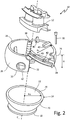
- FIG. 2 is an exploded view of spherical articulating fixture 10 that includes base 14 and clamp 16 for holding part 12.
- clamp 16 is an assembly comprised of first side 32, second side 34, and pin 36. Sides 32 and 34 are joined at hinge 38 and are rotatable relative to one another. Pin 36 is positioned through alternating holes (not shown) in sides 32 and 34, opposite of hinge 38, to lock sides 32 and 34 together when clamp 16 is fully assembled. Neither of pin 36 and hinge 38 extends beyond the complete sphere formed by radius RB.
- each of sides 32 and 34 also includes at least one contact surface 40 which is a surface configured to contact part 12 when clamp 16 is assembled.
- the outside of each of sides 32 and 34 are spherical and have the same radius of curvature RC and the same center point (not shown) when clamp 16 is assembled to hold part 12.
- clamp 16 In order to operate spherical articulating fixture 10, clamp 16 is opened and part 12 is placed on contact surfaces 40 of one of sides 32 and 34. Clamp 16 is then closed, placing the remaining contact surfaces 40 in contact with part 12. In order to insert pin 36 into sides 32 and 34, sides 32 and 34 are squeezed together by the operator using port 42. While only one port 42 is visible on first side 32, there is another port 42 on second side 34.
- clamp 16 is assembled, it is lifted above base 14. Then clamp 16 is moved vertically downward and placed in bowl 20 such that external surface 26 is in contact with at least rim 24. If radius RC is substantially the same as radius RB, then external surface 26 will also be in contact with internal surface 22. At this time, the operator can work on part 12, for example, by applying braze paste to a particular area of part 12 through, for example, first end 28. Then operator can turn part 12 by rotating clamp 16 in bowl 20 to work on another area of part 12, for example, through second end 30.
- clamp 16 can lift clamp 16 off of base 14 and place it, for example, on a workbench (not shown). The operator can then disassemble clamp 16 by removing pin 36 and part 12.
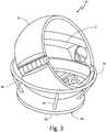
- FIG. 3 is a perspective view of an alternate embodiment spherical articulating fixture 60 with clamp 16 and part 12 in a different orientation from FIG. 1 . While part 12 and clamp 16 can be the same as part 12 and clamp 16 of FIGS. 1 and 2 , base 64 differs from base 14 of FIGS. 1 and 2 . More specifically, base 64 comprises bottom 68 and rim 74 with a plurality of spaced apart support members 94 extending between bottom 68 and rim 74.
- spherical articulating fixture 60 allows for any debris on part 12 (such as excess braze paste) to drop clear of part 12. This can occur statically, or as clamp 16 is rotated into different positions, for example, from the position of FIG. 1 to the position of FIG. 3 . Such a function can also be accomplished in spherical articulating fixture 10 of FIGS. 1 and 2 by including a hole (not shown) that extends through bottom 18 and bowl 20.
- FIG. 4 is a perspective view of additive manufacturing apparatus 100.
- FIG. 4 shows an additive manufacturing apparatus which uses laser additive manufacturing to create a three-dimensional object out of sinterable, pulverulent material. While direct metal laser sintering (DMLS) is described, other additive manufacturing techniques may be employed, such as, for example, laser powder bed fusion, electron beam powder bed fusion, laser powder deposition, electron beam wire, and selective laser sintering.
- DMLS direct metal laser sintering
- Additive manufacturing apparatus 100 includes computer 101 and a set of optical components, including laser 102, mirror 104, and moving optical head 106, which guide laser beam 108 according to the instructions from computer 101.
- Laser 102 may be any source of heating radiation, such as a CO2 laser.
- Additive manufacturing apparatus 100 also includes frame 110, pulverulent material 112, and coater 114, which are used for powder containment and application.
- Pulverulent material 112 may be any material suitable for use as a TOBI. Typically, pulverulent material 112 will be some combination of ceramic and/or metal.
- pulverulent material 112 may be steel, stainless steel, or a high temperature superalloy.
- Coater 114 is arranged along a surface of frame 110, and may be moved across the surface of frame 110. Coater 114 may be, for example, a knife blade or a roller. As shown in FIG. 4 , partially built base 14A is present inside frame 110.
- a user creates a computer file for computer 101 that defines a component with particular features, such as base 14 and/or clamp 16 (shown in FIG. 1 ), in layers (that can be of different thicknesses).
- Computer 101 then controls the optical equipment to create the component.
- Laser 102 creates laser beam 108 which can be used for melting, sintering, or cutting.
- Laser 102 is pointed towards mirror 104, which is arranged to deflect laser beam 108 toward moving optical head 106.
- moving optical head 106 directs laser beam 108 towards areas within frame 110, which holds pulverulent material 112.
- the areas melted or sintered form a layer of base 14 and/or clamp 16.
- partially built base 14A is shown being built up on a layer-by-layer basis. Areas adjacent to partially built base 14A can remain unmelted or unsintered to form bowl 20 (shown in FIG. 2 ) and can provide separation in the situation where base 14 and clamp 16 are being built simultaneously to ensure that base 14 is not permanently connected to clamp 16.
- the support holding partially built base 14A (shown later in FIG. 5 ) is lowered by the thickness of one layer of pulverulent material 112, and additional pulverulent material 112 is added on top of the existing structures using coater 114. Then new layer of pulverulent material 112 is melted or sintered to the top of partially built base 14A, and the process is repeated. By repeating the process several times, a layer-by-layer object, such as a complete base 14 can be manufactured.
- clamp 16 can be simultaneously manufactured or manufactured at a separate time or in a separate additive manufacturing apparatus 100.
- FIG. 5 is a cross section view of additive manufacturing apparatus 100 along line 5-5 in FIG. 4 .
- FIG. 5 is a cutaway view that shows the operation of additive manufacturing apparatus 100.
- FIG. 5 shows a DMLS apparatus, but it will be understood by those skilled in the art that other additive manufacturing techniques and apparatuses may be used, such as, for example, laser powder bed fusion, electron beam powder bed fusion, laser powder deposition, electron beam wire, and selective laser sintering.
- Additive manufacturing apparatus 100 as shown in FIG. 5 includes many of the same parts as those shown in FIG. 4 , such as frame 110, pulverulent material 112, coater 114, and partially built base 14A.
- FIG. 5 also shows component support 116 and material supply support 118.
- Component support 116 may be used to raise or lower partially built base 14A.
- Material supply support 118 may be raised to elevate or lower pulverulent material 112 above the working surface of frame 110.
- FIG. 5 shows the arrangement of component support 116 and material supply support 118 in addition to the arrangement of parts shown in FIG. 4 .
- partially built base 14A rests on component support 116.
- pulverulent material 112 rests on material supply support 118.
- component support 116 is lowered and material supply support 118 is raised.
- Coater 114 scrapes a layer of pulverulent material 112 off of the top of the supply side and applies it in a layer across the top of partially built base 14A. The process is then repeated until base 14 (shown in FIG. 1 ) is complete.
- the thickness of the layers can be set to adjust the surface finish of base 14 and/or clamp 16 (shown in FIG. 1 ).
- the appropriate surface finishes can be selected to provide sufficient friction to prevent spontaneous movement of clamp 16 in base 14, but permit sufficiently easy movement of clamp 16 in base 14 by the operator of spherical articulating fixture 10 (shown in FIG. 1 ).
- the thickness of layers can be varied to produce different surface finishes at different locations.
- the thickness of layers at rim 24 can be smaller than the thickness of layers at bottom 18 (both shown in FIG. 1 ) in order to rapidly manufacture most of base 14 while still having the appropriately finished surface for contacting clamp 16.
- FIGS. 4 and 5 show one possible way of additively manufacturing spherical articulating fixture 10 as disclosed above in reference to FIGS. 1 and 2 or spherical articulating fixture 60 as disclosed above in reference to FIG. 3 .
- Alternative methods for additively manufacturing components are possible. For example, laser powder bed fusion, electron beam powder bed fusion, laser powder deposition, electron beam wire, or selective laser sintering may be used to create objects in an additive fashion.
- a fixture includes: a base having a bottom and an elevated rim; and a clamp having a clamp exterior in a shape of a portion of a clamp sphere, the clamp including a component space that is positioned wholly within the clamp sphere; wherein the clamp is positioned such that the clamp exterior is in contact with the rim.
- the fixture of the preceding paragraph can optionally include, additionally and/or alternatively, any one or more of the following features, configurations and/or additional components:
- clamp can include a planar side.
- the clamp can comprise: a first side comprising: a first exterior having a first shape of a first portion of a first sphere; and a first interior opposite of the first exterior having a first component contact surface that partially defines the component space; and a second side comprising: a second exterior having a second shape of a second portion of a second sphere; and a second interior opposite of the second exterior having a second component contact surface that partially defines the component space; wherein the first side is connectable to the second side to form an assembled clamp wherein the first sphere and the second sphere share a common radius and a common centerpoint with the clamp sphere and the component space does not extend beyond the clamp sphere.
- a further embodiment of any of the foregoing fixtures, wherein the assembled clamp can form a spherical segment outside of which the component space at most extends through a first end of the spherical segment.
- a further embodiment of any of the foregoing fixtures wherein the first side of the clamp can be rotatably connected to the second side of the clamp at a hinge.
- a further embodiment of any of the foregoing fixtures wherein the first side can be connectable to the second side using a pin inserted into the first side and the second side opposite of the hinge.
- fixture can further comprise: a bowl that extends between the bottom and the rim, the bowl having a spherical interior surface.
- fixture can further comprise: a plurality of spaced apart support members that extends between the bottom and the rim.
- fixture can further comprise: a component positioned in the component space, wherein the center of gravity of the clamp with the component is positioned along an axis extending from the center of the rim.
- a method of using a fixture that includes a clamp with a spherical exterior, a first portion with a first contact surface, a second portion with a second contact surface, and a base with a spherical or circular rim of the base, the method according to an exemplary embodiment of this disclosure, among other possible things includes: placing a component in contact with the first contact surface of the first portion of the clamp; placing the second contact surface of the second portion of the clamp in contact with the component; placing the spherical exterior of the clamp into contact with the rim of the base such that the component is in a first orientation; applying a coating to a first area of the component; and exerting force on the clamp to orient the component in a second orientation.
- the method of the preceding paragraph can optionally include, additionally and/or alternatively, any one or more of the following features, configurations and/or additional components:
- placing the second contact surface in contact with the component can comprise rotating the second portion about a hinge that connects the first portion to the second portion.
- placing the second contact surface in contact with the component can comprise inserting a pin to connect the first portion to the second portion.
- placing the clamp into contact with the rim can comprise moving the clamp vertically downward from above the base.
- a fixture includes a base having a bottom and an elevated rim, and a clamp having an exterior in a shape of a portion of a sphere, the clamp including a component space that is positioned wholly within the sphere, wherein the clamp is configured to be positioned in in contact with the rim, the fixture being made by the steps of: selectively sintering a first layer of pulverulent material within a frame to make a partially built fixture; lowering the partially built fixture; adding a second layer of pulverulent material on top of the partially built fixture; and selectively sintering the second layer of pulverulent material to the partially built fixture.
- the method of the preceding paragraph can optionally include, additionally and/or alternatively, any one or more of the following features, configurations and/or additional components:
Landscapes
- Engineering & Computer Science (AREA)
- Mechanical Engineering (AREA)
- Chemical & Material Sciences (AREA)
- Manufacturing & Machinery (AREA)
- Materials Engineering (AREA)
- Physics & Mathematics (AREA)
- Optics & Photonics (AREA)
- Powder Metallurgy (AREA)
Abstract
Description
- This application relates to fixtures for holding components, and more particularly, to an articulating fixture for holding components while work is being performed on them.
- Some gas turbine engine components are brazed together which requires the application of braze paste to one or more components. The application of braze paste is traditionally a manual process wherein operators hold the components in their hand(s) and manipulate them in order to apply the paste to all of the appropriate areas. During this process, the operators can transfer the paste to areas that are not supposed to receive it (for example, airfoil aerodynamic surfaces). The paste can be difficult to remove and can irreparably contaminate the component, causing waste. In addition, operators can be fatigued by having to repeatedly hold and manipulate the parts while applying the paste.
- According to one embodiment, a fixture includes a base with a bottom and a rim, a clamp with an exterior in a shape of a portion of a clamp sphere and a component space that is wholly within the clamp sphere, wherein the clamp is positioned such that the clamp exterior is in contact with the rim.
- According to another embodiment, a method of using a fixture that includes a clamp with a spherical exterior, a first portion with a first contact surface, a second portion with a second contact surface, and a base with a spherical or circular rim of the base, the method including placing a component in contact with the first contact surface of the first portion of the clamp. The method also includes placing the second contact surface of the second portion of the clamp in contact with the component, placing the spherical exterior of the clamp into contact with the rim of the base such that the component is in a first orientation, applying a coating to a first area of the component, and exerting force on the clamp to orient the component in a second orientation.
- According to another embodiment, a fixture includes a base having a bottom and an elevated rim, and a clamp having an exterior in a shape of a portion of a sphere, the clamp including a component space that is positioned wholly within the sphere, wherein the clamp is configured to be positioned in in contact with the rim. The fixture is made by the steps of selectively sintering a first layer of pulverulent material within a frame to make a partially built fixture, lowering the partially built fixture, adding a second layer of pulverulent material on top of the partially built fixture, and selectively sintering the second layer of pulverulent material to the partially built fixture.
-
-
FIG. 1 is a perspective view of a spherical articulating fixture with a component or part. -
FIG. 2 is an exploded view of the spherical articulating fixture that includes a base and a clamp for holding the part. -
FIG. 3 is a perspective view of an alternate embodiment spherical articulating fixture with the clamp and part in a different orientation fromFIG. 1 . -
FIG. 4 is a perspective view of an additive manufacturing apparatus. -
FIG. 5 is a cross section view of the additive manufacturing apparatus along line 5-5 inFIG. 4 . -
FIG. 1 is a perspective view of spherical articulatingfixture 10 withpart 12. In the illustrated embodiment,base 14 includes aplanar bottom 18 such thatbase 14 can rest stably on, for example, a workbench (not shown). Extending upward frombottom 18 isbowl 20.Bowl 20 has a sphericalinternal surface 22 that terminates atrim 24.Internal surface 22 has a radius of curvature RB (shown inFIG. 2 ) and subtends less than an entire hemisphere. Rim 24 is substantially planar and has a circular shape. -
Clamp 16 has a sphericalexternal surface 26 which is in the form of a spherical segment with a radius of curvature RC (shown inFIG. 2 ). More specifically,external surface 26 has the form of a sphere that is truncated by two parallel planes atfirst end 28 and second end 30 (shown inFIG. 2 ).Clamp 16 is configured to be positioned inbowl 20 so to be constrained laterally and vertically downwards byrim 24, althoughclamp 16 is not constrained rotationally or vertically upwards. In this manner,clamp 16 does not solely contactbottom 18 ofbase 14, and clamp is rotatable withinbowl 20. Therefore, radius RC is substantially equal to or greater than radius RB, andclamp 16 has a height H that is sufficient to provide vertical overlap betweeninternal surface 22 ofbowl 20 andexternal surface 26 ofclamp 16. In such a configuration, radii of curvature ofends 28 and 30 (not shown) are smaller than radius RB. -
Clamp 16 includes a component space into whichpart 12 can be secured. Becausepart 12 is secured inclamp 16 inFIG. 1 , the component space ofclamp 16 is indicated bypart 12 inFIG. 1 . The component space does not extend beyond a complete sphere formed by radius RB and only extends beyond at most one ofends 28 and 30 (shown inFIG. 2 ). In such a configuration,clamp 16 can rest stably onsecond end 30, on, for example, a workbench (not shown) whileclamp 16 is holdingpart 12. In addition, the center of gravity ofclamp 16 when holdingpart 12 is approximately in the center of the complete sphere formed by radius RB. - The components and configuration of spherical articulating
fixture 10 allow forpart 12 to be held inclamp 16 and forclamp 16 to be stabilized inbase 14 in any orientation selected by an operator (not shown). This is due to the force of gravity enabling friction betweenbase 14 andclamp 16, and not due tobase 14 andclamp 16 being mechanically connected together as in the prior art. Because the center of gravity ofclamp 16 withpart 12 is centered in the complete sphere formed by radius RB, this center of gravity will approximately lie upon a vertical axis extending from the center ofrim 24. This arrangement minimizes or eliminates any torque onclamp 16 due to the center of gravity being offset from the center ofclamp 16. Thereby, the operator is free to exert force onclamp 16 to rotate it and change its orientation. Thereby,part 12 can be oriented in a single or multiple advantageous orientations so that, for example,part 12 can be inspected or have braze paste or another coating (not shown) applied to particular areas ofpart 12. -
FIG. 2 is an exploded view of spherical articulatingfixture 10 that includesbase 14 andclamp 16 for holdingpart 12. In the illustrated embodiment,clamp 16 is an assembly comprised offirst side 32,second side 34, andpin 36.Sides hinge 38 and are rotatable relative to one another.Pin 36 is positioned through alternating holes (not shown) insides hinge 38, to locksides clamp 16 is fully assembled. Neither ofpin 36 andhinge 38 extends beyond the complete sphere formed by radius RB. - The inside of each of
sides contact surface 40 which is a surface configured to contactpart 12 whenclamp 16 is assembled. The outside of each ofsides clamp 16 is assembled to holdpart 12. - In order to operate spherical articulating
fixture 10,clamp 16 is opened andpart 12 is placed oncontact surfaces 40 of one ofsides Clamp 16 is then closed, placing theremaining contact surfaces 40 in contact withpart 12. In order to insertpin 36 intosides sides operator using port 42. While only oneport 42 is visible onfirst side 32, there is anotherport 42 onsecond side 34. - Once
clamp 16 is assembled, it is lifted abovebase 14. Thenclamp 16 is moved vertically downward and placed inbowl 20 such thatexternal surface 26 is in contact with at leastrim 24. If radius RC is substantially the same as radius RB, thenexternal surface 26 will also be in contact withinternal surface 22. At this time, the operator can work onpart 12, for example, by applying braze paste to a particular area ofpart 12 through, for example,first end 28. Then operator can turnpart 12 by rotatingclamp 16 inbowl 20 to work on another area ofpart 12, for example, throughsecond end 30. - Once all of the work operations are finished, the operator can lift
clamp 16 off ofbase 14 and place it, for example, on a workbench (not shown). The operator can then disassembleclamp 16 by removingpin 36 andpart 12. -
FIG. 3 is a perspective view of an alternate embodiment spherical articulatingfixture 60 withclamp 16 andpart 12 in a different orientation fromFIG. 1 . Whilepart 12 andclamp 16 can be the same aspart 12 andclamp 16 ofFIGS. 1 and2 ,base 64 differs frombase 14 ofFIGS. 1 and2 . More specifically,base 64 comprisesbottom 68 andrim 74 with a plurality of spaced apartsupport members 94 extending betweenbottom 68 andrim 74. - The configuration of spherical articulating
fixture 60 allows for any debris on part 12 (such as excess braze paste) to drop clear ofpart 12. This can occur statically, or asclamp 16 is rotated into different positions, for example, from the position ofFIG. 1 to the position ofFIG. 3 . Such a function can also be accomplished in spherical articulatingfixture 10 ofFIGS. 1 and2 by including a hole (not shown) that extends through bottom 18 andbowl 20. -
FIG. 4 is a perspective view ofadditive manufacturing apparatus 100. In particular,FIG. 4 shows an additive manufacturing apparatus which uses laser additive manufacturing to create a three-dimensional object out of sinterable, pulverulent material. While direct metal laser sintering (DMLS) is described, other additive manufacturing techniques may be employed, such as, for example, laser powder bed fusion, electron beam powder bed fusion, laser powder deposition, electron beam wire, and selective laser sintering. -
Additive manufacturing apparatus 100 includescomputer 101 and a set of optical components, includinglaser 102,mirror 104, and movingoptical head 106, which guidelaser beam 108 according to the instructions fromcomputer 101.Laser 102 may be any source of heating radiation, such as a CO2 laser.Additive manufacturing apparatus 100 also includesframe 110,pulverulent material 112, andcoater 114, which are used for powder containment and application.Pulverulent material 112 may be any material suitable for use as a TOBI. Typically,pulverulent material 112 will be some combination of ceramic and/or metal. For example,pulverulent material 112 may be steel, stainless steel, or a high temperature superalloy.Coater 114 is arranged along a surface offrame 110, and may be moved across the surface offrame 110.Coater 114 may be, for example, a knife blade or a roller. As shown inFIG. 4 , partially builtbase 14A is presentinside frame 110. - A user creates a computer file for
computer 101 that defines a component with particular features, such asbase 14 and/or clamp 16 (shown inFIG. 1 ), in layers (that can be of different thicknesses).Computer 101 then controls the optical equipment to create the component.Laser 102 createslaser beam 108 which can be used for melting, sintering, or cutting.Laser 102 is pointed towardsmirror 104, which is arranged to deflectlaser beam 108 toward movingoptical head 106. Generally, movingoptical head 106 directslaser beam 108 towards areas withinframe 110, which holdspulverulent material 112. Generally, the areas melted or sintered form a layer ofbase 14 and/orclamp 16. In FIG. 6, partially builtbase 14A is shown being built up on a layer-by-layer basis. Areas adjacent to partially builtbase 14A can remain unmelted or unsintered to form bowl 20 (shown inFIG. 2 ) and can provide separation in the situation wherebase 14 and clamp 16 are being built simultaneously to ensure thatbase 14 is not permanently connected to clamp 16. - After each layer of partially built
base 14A is finished, the support holding partially builtbase 14A (shown later inFIG. 5 ) is lowered by the thickness of one layer ofpulverulent material 112, and additionalpulverulent material 112 is added on top of the existingstructures using coater 114. Then new layer ofpulverulent material 112 is melted or sintered to the top of partially builtbase 14A, and the process is repeated. By repeating the process several times, a layer-by-layer object, such as acomplete base 14 can be manufactured. In addition, clamp 16 can be simultaneously manufactured or manufactured at a separate time or in a separateadditive manufacturing apparatus 100. -
FIG. 5 is a cross section view ofadditive manufacturing apparatus 100 along line 5-5 inFIG. 4 .FIG. 5 is a cutaway view that shows the operation ofadditive manufacturing apparatus 100.FIG. 5 shows a DMLS apparatus, but it will be understood by those skilled in the art that other additive manufacturing techniques and apparatuses may be used, such as, for example, laser powder bed fusion, electron beam powder bed fusion, laser powder deposition, electron beam wire, and selective laser sintering. -
Additive manufacturing apparatus 100 as shown inFIG. 5 includes many of the same parts as those shown inFIG. 4 , such asframe 110,pulverulent material 112,coater 114, and partially builtbase 14A.FIG. 5 also showscomponent support 116 andmaterial supply support 118.Component support 116 may be used to raise or lower partially builtbase 14A.Material supply support 118 may be raised to elevate or lowerpulverulent material 112 above the working surface offrame 110. -
FIG. 5 shows the arrangement ofcomponent support 116 andmaterial supply support 118 in addition to the arrangement of parts shown inFIG. 4 . As can be seen inFIG. 5 , partially builtbase 14A rests oncomponent support 116. Likewise,pulverulent material 112 rests onmaterial supply support 118. - As each layer of partially built
base 14A is melted or sintered,component support 116 is lowered andmaterial supply support 118 is raised.Coater 114 scrapes a layer ofpulverulent material 112 off of the top of the supply side and applies it in a layer across the top of partially builtbase 14A. The process is then repeated until base 14 (shown inFIG. 1 ) is complete. The thickness of the layers can be set to adjust the surface finish ofbase 14 and/or clamp 16 (shown inFIG. 1 ). The appropriate surface finishes can be selected to provide sufficient friction to prevent spontaneous movement ofclamp 16 inbase 14, but permit sufficiently easy movement ofclamp 16 inbase 14 by the operator of spherical articulating fixture 10 (shown inFIG. 1 ). In addition, the thickness of layers can be varied to produce different surface finishes at different locations. For example, the thickness of layers atrim 24 can be smaller than the thickness of layers at bottom 18 (both shown inFIG. 1 ) in order to rapidly manufacture most ofbase 14 while still having the appropriately finished surface for contactingclamp 16. -
FIGS. 4 and5 show one possible way of additively manufacturing spherical articulatingfixture 10 as disclosed above in reference toFIGS. 1 and2 or spherical articulatingfixture 60 as disclosed above in reference toFIG. 3 . Alternative methods for additively manufacturing components are possible. For example, laser powder bed fusion, electron beam powder bed fusion, laser powder deposition, electron beam wire, or selective laser sintering may be used to create objects in an additive fashion. - The following are non-exclusive descriptions of possible embodiments of the present invention.
- A fixture according to an exemplary embodiment of this disclosure, among other possible things includes: a base having a bottom and an elevated rim; and a clamp having a clamp exterior in a shape of a portion of a clamp sphere, the clamp including a component space that is positioned wholly within the clamp sphere; wherein the clamp is positioned such that the clamp exterior is in contact with the rim.
- The fixture of the preceding paragraph can optionally include, additionally and/or alternatively, any one or more of the following features, configurations and/or additional components:
- A further embodiment of the foregoing fixture, wherein the portion of the sphere can be a spherical segment.
- A further embodiment of any of the foregoing fixtures, wherein the clamp can include a planar side.
- A further embodiment of any of the foregoing fixtures, wherein the clamp can comprise: a first side comprising: a first exterior having a first shape of a first portion of a first sphere; and a first interior opposite of the first exterior having a first component contact surface that partially defines the component space; and a second side comprising: a second exterior having a second shape of a second portion of a second sphere; and a second interior opposite of the second exterior having a second component contact surface that partially defines the component space; wherein the first side is connectable to the second side to form an assembled clamp wherein the first sphere and the second sphere share a common radius and a common centerpoint with the clamp sphere and the component space does not extend beyond the clamp sphere.
- A further embodiment of any of the foregoing fixtures, wherein the assembled clamp can form a spherical segment outside of which the component space at most extends through a first end of the spherical segment.
- A further embodiment of any of the foregoing fixtures, wherein the first side of the clamp can be rotatably connected to the second side of the clamp at a hinge.
- A further embodiment of any of the foregoing fixtures, wherein the first side can be connectable to the second side opposite of the hinge.
- A further embodiment of any of the foregoing fixtures, wherein the first side can be connectable to the second side using a pin inserted into the first side and the second side opposite of the hinge.
- A further embodiment of any of the foregoing fixtures, wherein the hinge and the pin can be positioned wholly within the clamp sphere.
- A further embodiment of any of the foregoing fixtures, wherein the fixture can further comprise: a bowl that extends between the bottom and the rim, the bowl having a spherical interior surface.
- A further embodiment of any of the foregoing fixtures, wherein the fixture can further comprise: a plurality of spaced apart support members that extends between the bottom and the rim.
- A further embodiment of any of the foregoing fixtures, wherein the fixture can further comprise: a component positioned in the component space, wherein the center of gravity of the clamp with the component is positioned along an axis extending from the center of the rim.
- A method of using a fixture that includes a clamp with a spherical exterior, a first portion with a first contact surface, a second portion with a second contact surface, and a base with a spherical or circular rim of the base, the method according to an exemplary embodiment of this disclosure, among other possible things includes: placing a component in contact with the first contact surface of the first portion of the clamp; placing the second contact surface of the second portion of the clamp in contact with the component; placing the spherical exterior of the clamp into contact with the rim of the base such that the component is in a first orientation; applying a coating to a first area of the component; and exerting force on the clamp to orient the component in a second orientation.
- The method of the preceding paragraph can optionally include, additionally and/or alternatively, any one or more of the following features, configurations and/or additional components:
- A further embodiment of the foregoing method, wherein the method can further comprise: applying a coating to a second area of the component that is different than the first area.
- A further embodiment of any of the foregoing methods, wherein placing the second contact surface in contact with the component can comprise rotating the second portion about a hinge that connects the first portion to the second portion.
- A further embodiment of any of the foregoing methods, wherein placing the second contact surface in contact with the component can comprise inserting a pin to connect the first portion to the second portion.
- A further embodiment of any of the foregoing methods, wherein placing the clamp into contact with the rim can comprise moving the clamp vertically downward from above the base.
- A fixture according to an exemplary embodiment of this disclosure, among other possible things includes a base having a bottom and an elevated rim, and a clamp having an exterior in a shape of a portion of a sphere, the clamp including a component space that is positioned wholly within the sphere, wherein the clamp is configured to be positioned in in contact with the rim, the fixture being made by the steps of: selectively sintering a first layer of pulverulent material within a frame to make a partially built fixture; lowering the partially built fixture; adding a second layer of pulverulent material on top of the partially built fixture; and selectively sintering the second layer of pulverulent material to the partially built fixture.
- The method of the preceding paragraph can optionally include, additionally and/or alternatively, any one or more of the following features, configurations and/or additional components:
- A further embodiment of the foregoing method, wherein the fixture can be made by the further steps of: lowering the partially built fixture after selectively sintering the second layer; adding a third layer of pulverant material on top of the partially built fixture; and selectively sintering the second layer of pulverant material to the partially built fixture; wherein the third layer of pulverant material is substantially larger than the second layer of pulverant material.
- A further embodiment of any of the foregoing methods, wherein the clamp can be formed simultaneously with the base.
- While the invention has been described with reference to an exemplary embodiment(s), it will be understood by those skilled in the art that various changes may be made and equivalents may be substituted for elements thereof without departing from the scope of the invention. In addition, many modifications may be made to adapt a particular situation or material to the teachings of the invention without departing from the essential scope thereof. Therefore, it is intended that the invention not be limited to the particular embodiment(s) disclosed, but that the invention will include all embodiments falling within the scope of the appended claims.
Claims (15)
- A fixture comprising:a base having a bottom and an elevated rim; anda clamp having a clamp exterior in a shape of a portion of a clamp sphere, the clamp including a component space that is positioned wholly within the clamp sphere;wherein the clamp is positioned such that the clamp exterior is in contact with the rim.
- The fixture of claim 1, wherein the portion of the sphere is a spherical segment.
- The fixture of claim 1 or 2, wherein the clamp includes a planar side.
- The fixture of claim 1, 2 or 3, wherein the clamp comprises:a first side comprising:a first exterior having a first shape of a first portion of a first sphere; anda first interior opposite of the first exterior having a first component contact surface that partially defines the component space; anda second side comprising:a second exterior having a second shape of a second portion of a second sphere; anda second interior opposite of the second exterior having a second component contact surface that partially defines the component space;wherein the first side is connectable to the second side to form an assembled clamp wherein the first sphere and the second sphere share a common radius and a common centerpoint with the clamp sphere and the component space does not extend beyond the clamp sphere.
- The fixture of claim 4, wherein the assembled clamp forms a spherical segment outside of which the component space at most extends through a first end of the spherical segment.
- The fixture of claim 4 or 5, wherein the first side of the clamp is rotatably connected to the second side of the clamp at a hinge,
wherein, optionally, the first side is connectable to the second side opposite of the hinge,
wherein, optionally, the first side is connectable to the second side using a pin inserted into the first side and the second side opposite of the hinge,
wherein, optionally, the hinge and the pin are positioned wholly within the clamp sphere. - The fixture of any preceding claim, further comprising:a bowl that extends between the bottom and the rim, the bowl having a spherical interior surface.
- The fixture of any preceding claim, further comprising:a plurality of spaced apart support members that extends between the bottom and the rim.
- The fixture of any preceding claim, further comprising:a component positioned in the component space, wherein the center of gravity of the clamp with the component is positioned along an axis extending from the center of the rim.
- A method of using a fixture that includes a clamp with a spherical exterior, a first portion with a first contact surface, a second portion with a second contact surface, and a base with a spherical or circular rim of the base, the method comprising:placing a component in contact with the first contact surface of the first portion of the clamp;placing the second contact surface of the second portion of the clamp in contact with the component;placing the spherical exterior of the clamp into contact with the rim of the base such that the component is in a first orientation;applying a coating to a first area of the component; andexerting force on the clamp to orient the component in a second orientation.
- The method of claim 10, further comprising:applying a coating to a second area of the component that is different than the first area.
- The method of claim 10 or 11, wherein placing the second contact surface in contact with the component comprises rotating the second portion about a hinge that connects the first portion to the second portion,
wherein, optionally, placing the second contact surface in contact with the component comprises inserting a pin to connect the first portion to the second portion. - The method of claim 10, 11 or 12, wherein placing the clamp into contact with the rim comprises moving the clamp vertically downward from above the base.
- A fixture comprising a base having a bottom and an elevated rim, and a clamp having an exterior in a shape of a portion of a sphere, the clamp including a component space that is positioned wholly within the sphere, wherein the clamp is configured to be positioned in in contact with the rim, the fixture being made by the steps of:selectively sintering a first layer of pulverulent material within a frame to make a partially built fixture;lowering the partially built fixture;adding a second layer of pulverulent material on top of the partially built fixture; andselectively sintering the second layer of pulverulent material to the partially built fixture.
- The fixture of claim 14, the fixture being made by the further steps of:lowering the partially built fixture after selectively sintering the second layer;adding a third layer of pulverant material on top of the partially built fixture; andselectively sintering the second layer of pulverant material to the partially built fixture;wherein the third layer of pulverant material is substantially larger than the second layer of pulverant material, and/orwherein, optionally, the clamp is formed simultaneously with the base.
Applications Claiming Priority (1)
| Application Number | Priority Date | Filing Date | Title |
|---|---|---|---|
| US15/418,093 US10300546B2 (en) | 2017-01-27 | 2017-01-27 | Spherical articulating fixture |
Publications (2)
| Publication Number | Publication Date |
|---|---|
| EP3357621A1 true EP3357621A1 (en) | 2018-08-08 |
| EP3357621B1 EP3357621B1 (en) | 2020-04-29 |
Family
ID=61024644
Family Applications (1)
| Application Number | Title | Priority Date | Filing Date |
|---|---|---|---|
| EP18153165.8A Active EP3357621B1 (en) | 2017-01-27 | 2018-01-24 | Spherical articulating fixture ; method of using such fixture |
Country Status (2)
| Country | Link |
|---|---|
| US (1) | US10300546B2 (en) |
| EP (1) | EP3357621B1 (en) |
Cited By (1)
| Publication number | Priority date | Publication date | Assignee | Title |
|---|---|---|---|---|
| CN110614415A (en) * | 2018-10-08 | 2019-12-27 | 上海航天精密机械研究所 | Automatic welding device for titanium alloy thin-wall spherical shell |
Families Citing this family (1)
| Publication number | Priority date | Publication date | Assignee | Title |
|---|---|---|---|---|
| CN114473929A (en) * | 2022-02-24 | 2022-05-13 | 江苏中为金属制造有限公司 | Rotating bracket for mounting vehicle tire |
Citations (4)
| Publication number | Priority date | Publication date | Assignee | Title |
|---|---|---|---|---|
| US2796788A (en) * | 1954-06-29 | 1957-06-25 | Donald I Bohn | Magnetically lockable universal vise support |
| US3867032A (en) * | 1973-03-20 | 1975-02-18 | Diharo Diamanten Handels Compa | Arrangement for objectively evaluating characteristics of gems, particularly diamonds |
| DE10340052A1 (en) * | 2003-08-28 | 2005-05-04 | Dieter Ronsdorf | Process to manufacture a flexible three-dimensional work-piece clamping or holding fixture by laser sintering or laser welding and selective hardening |
| US20070234549A1 (en) * | 2006-03-17 | 2007-10-11 | General Electric Company | Braze/weld manipulator and method of manipulating nozzles |
Family Cites Families (4)
| Publication number | Priority date | Publication date | Assignee | Title |
|---|---|---|---|---|
| US1530566A (en) * | 1922-11-09 | 1925-03-24 | Lobbett James Frank | Universal workholder |
| US1673990A (en) * | 1924-11-17 | 1928-06-19 | Allen E Bosley | Axle support |
| US4088129A (en) | 1976-11-15 | 1978-05-09 | Digiulio Mario | Appliance for foot orthosis |
| US6560890B1 (en) * | 2002-02-21 | 2003-05-13 | General Electric Company | Fixture for locating and clamping a part for laser drilling |
-
2017
- 2017-01-27 US US15/418,093 patent/US10300546B2/en active Active
-
2018
- 2018-01-24 EP EP18153165.8A patent/EP3357621B1/en active Active
Patent Citations (4)
| Publication number | Priority date | Publication date | Assignee | Title |
|---|---|---|---|---|
| US2796788A (en) * | 1954-06-29 | 1957-06-25 | Donald I Bohn | Magnetically lockable universal vise support |
| US3867032A (en) * | 1973-03-20 | 1975-02-18 | Diharo Diamanten Handels Compa | Arrangement for objectively evaluating characteristics of gems, particularly diamonds |
| DE10340052A1 (en) * | 2003-08-28 | 2005-05-04 | Dieter Ronsdorf | Process to manufacture a flexible three-dimensional work-piece clamping or holding fixture by laser sintering or laser welding and selective hardening |
| US20070234549A1 (en) * | 2006-03-17 | 2007-10-11 | General Electric Company | Braze/weld manipulator and method of manipulating nozzles |
Cited By (1)
| Publication number | Priority date | Publication date | Assignee | Title |
|---|---|---|---|---|
| CN110614415A (en) * | 2018-10-08 | 2019-12-27 | 上海航天精密机械研究所 | Automatic welding device for titanium alloy thin-wall spherical shell |
Also Published As
| Publication number | Publication date |
|---|---|
| US20180214965A1 (en) | 2018-08-02 |
| US10300546B2 (en) | 2019-05-28 |
| EP3357621B1 (en) | 2020-04-29 |
Similar Documents
| Publication | Publication Date | Title |
|---|---|---|
| CN105618749B (en) | The carrier mechanism used in method for repairing multiple parts at the same time | |
| US9539764B2 (en) | Usage of a witness mark to distinguish support structure from part | |
| EP3485508B1 (en) | Apparatus von handling a semiconductor wafer in an epitaxy reactor and method for manufacturing a semiconductor wafer with an epitactic layer | |
| US8731717B2 (en) | Methods for manipulating cutting elements for earth-boring drill bits and tools | |
| EP2855073B1 (en) | Method and device for improving the quality of the weld seam in friction stir welding | |
| EP3357621B1 (en) | Spherical articulating fixture ; method of using such fixture | |
| CN101269443B (en) | Process for resurfacing an aluminum alloy part | |
| JP6812123B2 (en) | 3D modeling equipment | |
| CN109414790A (en) | Method and apparatus for determining the reference focus orientation of the beam of the lathe based on beam by a sequence for executing test cutting on workpiece | |
| HUE031022T2 (en) | Resistance weld repairing of casing flange holes | |
| EP3632590B1 (en) | Additive manufacturing machine having reconfigurable gas nozzles | |
| JP6731495B2 (en) | System and method for manufacturing dental instruments | |
| WO2019092098A1 (en) | Support system for a production system, and workpiece holder for same | |
| US20050274479A1 (en) | Process and apparatus for assembly of wax trees | |
| EP2853678A2 (en) | Polycrystalline diamond compact bit manufacturing | |
| CN206263501U (en) | Robot welding plummer | |
| DE102008035730A1 (en) | Attaching a machining pin to a gem to be ground | |
| DE102016110877B4 (en) | Method for attaching a mobile machine tool and mobile machine tool | |
| CN109648086A (en) | Metal engrafting method, laser melting equipment based on selective laser fusion technology | |
| EP2022596B1 (en) | Method of performing a manual laser deposition using a weld filler | |
| CN220006614U (en) | Sealing ball positioning device | |
| DE102017112655B4 (en) | Handling device for a dental workpiece | |
| JP4860190B2 (en) | Rotating workpiece support device | |
| US12208440B2 (en) | Method and device for welding tool automation | |
| KR102084857B1 (en) | Tilting device |
Legal Events
| Date | Code | Title | Description |
|---|---|---|---|
| PUAI | Public reference made under article 153(3) epc to a published international application that has entered the european phase |
Free format text: ORIGINAL CODE: 0009012 |
|
| STAA | Information on the status of an ep patent application or granted ep patent |
Free format text: STATUS: THE APPLICATION HAS BEEN PUBLISHED |
|
| AK | Designated contracting states |
Kind code of ref document: A1 Designated state(s): AL AT BE BG CH CY CZ DE DK EE ES FI FR GB GR HR HU IE IS IT LI LT LU LV MC MK MT NL NO PL PT RO RS SE SI SK SM TR |
|
| AX | Request for extension of the european patent |
Extension state: BA ME |
|
| STAA | Information on the status of an ep patent application or granted ep patent |
Free format text: STATUS: REQUEST FOR EXAMINATION WAS MADE |
|
| 17P | Request for examination filed |
Effective date: 20190207 |
|
| RBV | Designated contracting states (corrected) |
Designated state(s): AL AT BE BG CH CY CZ DE DK EE ES FI FR GB GR HR HU IE IS IT LI LT LU LV MC MK MT NL NO PL PT RO RS SE SI SK SM TR |
|
| GRAP | Despatch of communication of intention to grant a patent |
Free format text: ORIGINAL CODE: EPIDOSNIGR1 |
|
| STAA | Information on the status of an ep patent application or granted ep patent |
Free format text: STATUS: GRANT OF PATENT IS INTENDED |
|
| INTG | Intention to grant announced |
Effective date: 20200107 |
|
| GRAS | Grant fee paid |
Free format text: ORIGINAL CODE: EPIDOSNIGR3 |
|
| GRAA | (expected) grant |
Free format text: ORIGINAL CODE: 0009210 |
|
| STAA | Information on the status of an ep patent application or granted ep patent |
Free format text: STATUS: THE PATENT HAS BEEN GRANTED |
|
| AK | Designated contracting states |
Kind code of ref document: B1 Designated state(s): AL AT BE BG CH CY CZ DE DK EE ES FI FR GB GR HR HU IE IS IT LI LT LU LV MC MK MT NL NO PL PT RO RS SE SI SK SM TR |
|
| REG | Reference to a national code |
Ref country code: GB Ref legal event code: FG4D |
|
| REG | Reference to a national code |
Ref country code: CH Ref legal event code: EP |
|
| REG | Reference to a national code |
Ref country code: DE Ref legal event code: R096 Ref document number: 602018004039 Country of ref document: DE |
|
| REG | Reference to a national code |
Ref country code: AT Ref legal event code: REF Ref document number: 1262564 Country of ref document: AT Kind code of ref document: T Effective date: 20200515 |
|
| REG | Reference to a national code |
Ref country code: IE Ref legal event code: FG4D |
|
| REG | Reference to a national code |
Ref country code: NL Ref legal event code: MP Effective date: 20200429 |
|
| REG | Reference to a national code |
Ref country code: LT Ref legal event code: MG4D |
|
| PG25 | Lapsed in a contracting state [announced via postgrant information from national office to epo] |
Ref country code: PT Free format text: LAPSE BECAUSE OF FAILURE TO SUBMIT A TRANSLATION OF THE DESCRIPTION OR TO PAY THE FEE WITHIN THE PRESCRIBED TIME-LIMIT Effective date: 20200831 Ref country code: SE Free format text: LAPSE BECAUSE OF FAILURE TO SUBMIT A TRANSLATION OF THE DESCRIPTION OR TO PAY THE FEE WITHIN THE PRESCRIBED TIME-LIMIT Effective date: 20200429 Ref country code: IS Free format text: LAPSE BECAUSE OF FAILURE TO SUBMIT A TRANSLATION OF THE DESCRIPTION OR TO PAY THE FEE WITHIN THE PRESCRIBED TIME-LIMIT Effective date: 20200829 Ref country code: FI Free format text: LAPSE BECAUSE OF FAILURE TO SUBMIT A TRANSLATION OF THE DESCRIPTION OR TO PAY THE FEE WITHIN THE PRESCRIBED TIME-LIMIT Effective date: 20200429 Ref country code: LT Free format text: LAPSE BECAUSE OF FAILURE TO SUBMIT A TRANSLATION OF THE DESCRIPTION OR TO PAY THE FEE WITHIN THE PRESCRIBED TIME-LIMIT Effective date: 20200429 Ref country code: NO Free format text: LAPSE BECAUSE OF FAILURE TO SUBMIT A TRANSLATION OF THE DESCRIPTION OR TO PAY THE FEE WITHIN THE PRESCRIBED TIME-LIMIT Effective date: 20200729 Ref country code: GR Free format text: LAPSE BECAUSE OF FAILURE TO SUBMIT A TRANSLATION OF THE DESCRIPTION OR TO PAY THE FEE WITHIN THE PRESCRIBED TIME-LIMIT Effective date: 20200730 |
|
| REG | Reference to a national code |
Ref country code: AT Ref legal event code: MK05 Ref document number: 1262564 Country of ref document: AT Kind code of ref document: T Effective date: 20200429 |
|
| PG25 | Lapsed in a contracting state [announced via postgrant information from national office to epo] |
Ref country code: HR Free format text: LAPSE BECAUSE OF FAILURE TO SUBMIT A TRANSLATION OF THE DESCRIPTION OR TO PAY THE FEE WITHIN THE PRESCRIBED TIME-LIMIT Effective date: 20200429 Ref country code: LV Free format text: LAPSE BECAUSE OF FAILURE TO SUBMIT A TRANSLATION OF THE DESCRIPTION OR TO PAY THE FEE WITHIN THE PRESCRIBED TIME-LIMIT Effective date: 20200429 Ref country code: RS Free format text: LAPSE BECAUSE OF FAILURE TO SUBMIT A TRANSLATION OF THE DESCRIPTION OR TO PAY THE FEE WITHIN THE PRESCRIBED TIME-LIMIT Effective date: 20200429 Ref country code: BG Free format text: LAPSE BECAUSE OF FAILURE TO SUBMIT A TRANSLATION OF THE DESCRIPTION OR TO PAY THE FEE WITHIN THE PRESCRIBED TIME-LIMIT Effective date: 20200729 |
|
| PG25 | Lapsed in a contracting state [announced via postgrant information from national office to epo] |
Ref country code: AL Free format text: LAPSE BECAUSE OF FAILURE TO SUBMIT A TRANSLATION OF THE DESCRIPTION OR TO PAY THE FEE WITHIN THE PRESCRIBED TIME-LIMIT Effective date: 20200429 Ref country code: NL Free format text: LAPSE BECAUSE OF FAILURE TO SUBMIT A TRANSLATION OF THE DESCRIPTION OR TO PAY THE FEE WITHIN THE PRESCRIBED TIME-LIMIT Effective date: 20200429 |
|
| PG25 | Lapsed in a contracting state [announced via postgrant information from national office to epo] |
Ref country code: EE Free format text: LAPSE BECAUSE OF FAILURE TO SUBMIT A TRANSLATION OF THE DESCRIPTION OR TO PAY THE FEE WITHIN THE PRESCRIBED TIME-LIMIT Effective date: 20200429 Ref country code: IT Free format text: LAPSE BECAUSE OF FAILURE TO SUBMIT A TRANSLATION OF THE DESCRIPTION OR TO PAY THE FEE WITHIN THE PRESCRIBED TIME-LIMIT Effective date: 20200429 Ref country code: RO Free format text: LAPSE BECAUSE OF FAILURE TO SUBMIT A TRANSLATION OF THE DESCRIPTION OR TO PAY THE FEE WITHIN THE PRESCRIBED TIME-LIMIT Effective date: 20200429 Ref country code: CZ Free format text: LAPSE BECAUSE OF FAILURE TO SUBMIT A TRANSLATION OF THE DESCRIPTION OR TO PAY THE FEE WITHIN THE PRESCRIBED TIME-LIMIT Effective date: 20200429 Ref country code: DK Free format text: LAPSE BECAUSE OF FAILURE TO SUBMIT A TRANSLATION OF THE DESCRIPTION OR TO PAY THE FEE WITHIN THE PRESCRIBED TIME-LIMIT Effective date: 20200429 Ref country code: AT Free format text: LAPSE BECAUSE OF FAILURE TO SUBMIT A TRANSLATION OF THE DESCRIPTION OR TO PAY THE FEE WITHIN THE PRESCRIBED TIME-LIMIT Effective date: 20200429 Ref country code: SM Free format text: LAPSE BECAUSE OF FAILURE TO SUBMIT A TRANSLATION OF THE DESCRIPTION OR TO PAY THE FEE WITHIN THE PRESCRIBED TIME-LIMIT Effective date: 20200429 Ref country code: ES Free format text: LAPSE BECAUSE OF FAILURE TO SUBMIT A TRANSLATION OF THE DESCRIPTION OR TO PAY THE FEE WITHIN THE PRESCRIBED TIME-LIMIT Effective date: 20200429 |
|
| REG | Reference to a national code |
Ref country code: DE Ref legal event code: R097 Ref document number: 602018004039 Country of ref document: DE |
|
| PG25 | Lapsed in a contracting state [announced via postgrant information from national office to epo] |
Ref country code: SK Free format text: LAPSE BECAUSE OF FAILURE TO SUBMIT A TRANSLATION OF THE DESCRIPTION OR TO PAY THE FEE WITHIN THE PRESCRIBED TIME-LIMIT Effective date: 20200429 Ref country code: PL Free format text: LAPSE BECAUSE OF FAILURE TO SUBMIT A TRANSLATION OF THE DESCRIPTION OR TO PAY THE FEE WITHIN THE PRESCRIBED TIME-LIMIT Effective date: 20200429 |
|
| PLBE | No opposition filed within time limit |
Free format text: ORIGINAL CODE: 0009261 |
|
| STAA | Information on the status of an ep patent application or granted ep patent |
Free format text: STATUS: NO OPPOSITION FILED WITHIN TIME LIMIT |
|
| RAP2 | Party data changed (patent owner data changed or rights of a patent transferred) |
Owner name: RAYTHEON TECHNOLOGIES CORPORATION |
|
| 26N | No opposition filed |
Effective date: 20210201 |
|
| PG25 | Lapsed in a contracting state [announced via postgrant information from national office to epo] |
Ref country code: SI Free format text: LAPSE BECAUSE OF FAILURE TO SUBMIT A TRANSLATION OF THE DESCRIPTION OR TO PAY THE FEE WITHIN THE PRESCRIBED TIME-LIMIT Effective date: 20200429 |
|
| PG25 | Lapsed in a contracting state [announced via postgrant information from national office to epo] |
Ref country code: MC Free format text: LAPSE BECAUSE OF FAILURE TO SUBMIT A TRANSLATION OF THE DESCRIPTION OR TO PAY THE FEE WITHIN THE PRESCRIBED TIME-LIMIT Effective date: 20200429 |
|
| REG | Reference to a national code |
Ref country code: CH Ref legal event code: PL |
|
| PG25 | Lapsed in a contracting state [announced via postgrant information from national office to epo] |
Ref country code: LU Free format text: LAPSE BECAUSE OF NON-PAYMENT OF DUE FEES Effective date: 20210124 |
|
| REG | Reference to a national code |
Ref country code: BE Ref legal event code: MM Effective date: 20210131 |
|
| PG25 | Lapsed in a contracting state [announced via postgrant information from national office to epo] |
Ref country code: CH Free format text: LAPSE BECAUSE OF NON-PAYMENT OF DUE FEES Effective date: 20210131 Ref country code: LI Free format text: LAPSE BECAUSE OF NON-PAYMENT OF DUE FEES Effective date: 20210131 |
|
| PG25 | Lapsed in a contracting state [announced via postgrant information from national office to epo] |
Ref country code: IE Free format text: LAPSE BECAUSE OF NON-PAYMENT OF DUE FEES Effective date: 20210124 |
|
| PG25 | Lapsed in a contracting state [announced via postgrant information from national office to epo] |
Ref country code: BE Free format text: LAPSE BECAUSE OF NON-PAYMENT OF DUE FEES Effective date: 20210131 |
|
| REG | Reference to a national code |
Ref country code: DE Ref legal event code: R081 Ref document number: 602018004039 Country of ref document: DE Owner name: RAYTHEON TECHNOLOGIES CORPORATION (N.D.GES.D.S, US Free format text: FORMER OWNER: UNITED TECHNOLOGIES CORPORATION, FARMINGTON, CONN., US Ref country code: DE Ref legal event code: R081 Ref document number: 602018004039 Country of ref document: DE Owner name: RTX CORPORATION (N.D.GES.D. STAATES DELAWARE),, US Free format text: FORMER OWNER: UNITED TECHNOLOGIES CORPORATION, FARMINGTON, CONN., US |
|
| P01 | Opt-out of the competence of the unified patent court (upc) registered |
Effective date: 20230520 |
|
| PG25 | Lapsed in a contracting state [announced via postgrant information from national office to epo] |
Ref country code: CY Free format text: LAPSE BECAUSE OF FAILURE TO SUBMIT A TRANSLATION OF THE DESCRIPTION OR TO PAY THE FEE WITHIN THE PRESCRIBED TIME-LIMIT Effective date: 20200429 |
|
| PG25 | Lapsed in a contracting state [announced via postgrant information from national office to epo] |
Ref country code: HU Free format text: LAPSE BECAUSE OF FAILURE TO SUBMIT A TRANSLATION OF THE DESCRIPTION OR TO PAY THE FEE WITHIN THE PRESCRIBED TIME-LIMIT; INVALID AB INITIO Effective date: 20180124 |
|
| PG25 | Lapsed in a contracting state [announced via postgrant information from national office to epo] |
Ref country code: MK Free format text: LAPSE BECAUSE OF FAILURE TO SUBMIT A TRANSLATION OF THE DESCRIPTION OR TO PAY THE FEE WITHIN THE PRESCRIBED TIME-LIMIT Effective date: 20200429 |
|
| PG25 | Lapsed in a contracting state [announced via postgrant information from national office to epo] |
Ref country code: TR Free format text: LAPSE BECAUSE OF FAILURE TO SUBMIT A TRANSLATION OF THE DESCRIPTION OR TO PAY THE FEE WITHIN THE PRESCRIBED TIME-LIMIT Effective date: 20200429 |
|
| PG25 | Lapsed in a contracting state [announced via postgrant information from national office to epo] |
Ref country code: MT Free format text: LAPSE BECAUSE OF FAILURE TO SUBMIT A TRANSLATION OF THE DESCRIPTION OR TO PAY THE FEE WITHIN THE PRESCRIBED TIME-LIMIT Effective date: 20200429 |
|
| REG | Reference to a national code |
Ref country code: DE Ref legal event code: R081 Ref document number: 602018004039 Country of ref document: DE Owner name: RTX CORPORATION (N.D.GES.D. STAATES DELAWARE),, US Free format text: FORMER OWNER: RAYTHEON TECHNOLOGIES CORPORATION (N.D.GES.D.STAATES DELAWARE), ARLINGTON, VA, US |
|
| PGFP | Annual fee paid to national office [announced via postgrant information from national office to epo] |
Ref country code: GB Payment date: 20251220 Year of fee payment: 9 |
|
| PGFP | Annual fee paid to national office [announced via postgrant information from national office to epo] |
Ref country code: FR Payment date: 20251217 Year of fee payment: 9 |
|
| PGFP | Annual fee paid to national office [announced via postgrant information from national office to epo] |
Ref country code: DE Payment date: 20251217 Year of fee payment: 9 |