EP3357616A1 - Dispositif de coupe destiné à l'usinage de pièces par enlevement de copeaux - Google Patents
Dispositif de coupe destiné à l'usinage de pièces par enlevement de copeaux Download PDFInfo
- Publication number
- EP3357616A1 EP3357616A1 EP18151896.0A EP18151896A EP3357616A1 EP 3357616 A1 EP3357616 A1 EP 3357616A1 EP 18151896 A EP18151896 A EP 18151896A EP 3357616 A1 EP3357616 A1 EP 3357616A1
- Authority
- EP
- European Patent Office
- Prior art keywords
- pipe socket
- cutting device
- cutting
- support surface
- tool holder
- Prior art date
- Legal status (The legal status is an assumption and is not a legal conclusion. Google has not performed a legal analysis and makes no representation as to the accuracy of the status listed.)
- Granted
Links
- 238000003754 machining Methods 0.000 title claims abstract description 8
- 239000005068 cooling lubricant Substances 0.000 claims abstract description 30
- 230000001747 exhibiting effect Effects 0.000 claims abstract description 4
- 238000007789 sealing Methods 0.000 claims description 10
- 239000002826 coolant Substances 0.000 claims description 9
- 239000000314 lubricant Substances 0.000 claims description 9
- 239000000463 material Substances 0.000 claims description 4
- 238000003780 insertion Methods 0.000 description 3
- 230000037431 insertion Effects 0.000 description 3
- 238000001816 cooling Methods 0.000 description 2
- 239000013536 elastomeric material Substances 0.000 description 2
- 230000007704 transition Effects 0.000 description 2
- 239000000853 adhesive Substances 0.000 description 1
- 230000001070 adhesive effect Effects 0.000 description 1
- 239000002131 composite material Substances 0.000 description 1
- 230000000694 effects Effects 0.000 description 1
- 230000013011 mating Effects 0.000 description 1
- 239000002184 metal Substances 0.000 description 1
Images


Classifications
-
- B—PERFORMING OPERATIONS; TRANSPORTING
- B23—MACHINE TOOLS; METAL-WORKING NOT OTHERWISE PROVIDED FOR
- B23B—TURNING; BORING
- B23B29/00—Holders for non-rotary cutting tools; Boring bars or boring heads; Accessories for tool holders
- B23B29/04—Tool holders for a single cutting tool
- B23B29/046—Tool holders for a single cutting tool with an intermediary toolholder
-
- B—PERFORMING OPERATIONS; TRANSPORTING
- B23—MACHINE TOOLS; METAL-WORKING NOT OTHERWISE PROVIDED FOR
- B23B—TURNING; BORING
- B23B2250/00—Compensating adverse effects during turning, boring or drilling
- B23B2250/12—Cooling and lubrication
Definitions
- the invention relates to a cutting device for machining workpieces, comprising at least one cutting tool having a clamping shank and in contact with the workpiece to be machined or standing cutting means, wherein the clamping shank comprises a plurality of components, one of which has the cutting means having support member and another is a position specification part which can be clamped independently of each other in an associated tool holder of a tool holder, wherein on the position setting part a support surface and on the support part of the support surface facing a support surface are formed in a use position in which the support member and the position specifying part in the receptacle of Tool holder are received, abut each other, and wherein the clamping shank is penetrated by at least one cooling lubricant channel, which is partially formed on a pipe sleeve arranged on one of the components and i n the other component dips.
- the workpiece to be machined which may be, for example, a metal rod, is in this case mounted on a spindle and is rotated by it, wherein a previously approached to the workpiece For example, it is possible to cut an annular groove over the circumference of the workpiece by means of the cutting tool.
- Cutting tools for machining are usually located in tool holders, one of which is arranged above the workpiece to be machined, which in turn is usually mounted to be linearly movable about an axis to a feed movement and thus the delivery of the respective cutting tool to the workpiece enable.
- the cutting tools are clamped in the tool holder by means of clamping means.
- clamping is to be solved to take the cutting tool from the recording. After replacing the cutting tools, insert the new tool back into the socket and clamp it.
- the new tool is to be aligned exactly, in particular with respect to its position with respect to the workpiece to be machined or with respect to the other located in the tool holder cutting tools. This is complicated and costs a lot of time. The change accuracy leaves something to be desired.
- cooling lubricant is brought into the area of the cutting edge.
- the supply of the cooling lubricant via at least one cooling lubricant channel, which is formed in the cutting tool.
- the object of the invention is therefore to provide a cutting device of the type mentioned above, with a quick tool change with high change accuracy is possible.
- the cutting device according to the invention according to the independent claim 1 is characterized in that the pipe socket while allowing all-round radial and tilting movements relative to the component on which it is arranged to float.
- the pipe socket is therefore radially movable on all sides and also tiltable relative to the component to which it is arranged. This makes it possible that the pipe socket aligns when clamping the support member in the receptacle and therefore there is always a correct fit between the support surface and the mating support surface with exact alignment of the pipe socket within the associated recording. This achieves a high degree of accuracy, which can be in the hundredth range. Escape errors during clamping of the support member are compensated by the floating bearing, resulting in a higher repeat accuracy.
- bearing means are provided for floating mounting of the pipe socket, which has a bearing receptacle on the associated component and at least one disposed between an inner wall of the bearing receptacle and a lateral surface of the pipe socket annular bearing element made of elastically yielding material.
- the elastically compliant material may be, for example, elastomeric material.
- the annular bearing element is designed as an O-ring or round cord sealing ring.
- the bearing receptacle has a receptacle formed separately from the associated component, which is penetrated by the pipe socket and in turn is received in a base bearing formed in the associated component.
- the receiving socket and the pipe socket together form a cooling lubricant adapter, if necessary, for example when worn, can be replaced.
- the bearing receptacle is formed directly in the associated component, for example by a particular circular receiving opening, in which then the annular bearing element is inserted, which then in this case between the lateral surface of the pipe socket and the inner wall of the receiving opening located.
- receiving socket and pipe socket as a preassembled module together in the base bearing of the associated component can be introduced, resulting in a simplification of assembly.
- the receiving socket on an external thread, which can be screwed with an internal thread of the base bearing.
- other types of mounting of the receiving socket in the base bearing would be conceivable, for example, an attachment by means of a latching or snap connection.
- a non-removable mounting of the receiving socket in the base bearing would be conceivable, for example with an adhesive connection.
- Axialantschstoffsch are provided which provide for an axial stop of the pipe socket when inserted into the receiving socket. This prevents the pipe socket from detaching in an unforeseen manner in the axial direction from the mounting base, in particular when separating the position specification part and the support part.
- a corresponding formed to the pipe socket nozzle receptacle is formed on the not provided with the pipe socket component, in which the pipe socket is received in the position of use.
- At least one annular sealing element is arranged between an inner wall of the receptacle and a lateral surface of the pipe socket.
- the annular sealing element is designed as an O-ring or round cord sealing ring.
- the O-ring made of elastomeric material.
- the support surface are arranged on the end face of the position presetting part facing the support part and the counter support surface on the front side of the support part facing the position preselection part.
- the support surface and the counter support surface are each formed as inclined in the same direction inclined surfaces.
- the support surface is formed on a projecting from the rest of the front side forward projection and preferably springs back in the direction of an outer side to the center of the position specification part to the rest of the front side.
- the counter support surface springs back from the rest of the front side to an outer side of the support part.
- a tool holder is provided with a plurality of tool holders for associated cutting tools.
- the tool holders are each associated with clamping means which have a first clamping unit serving for clamping the position specification part and a second clamping unit which can be operated in particular independently of this for clamping the carrying part.
- the at least one coolant lubricant channel has a supply channel section extending in the position specification part between a coolant lubricant inlet opening and the pipe socket.
- the at least one coolant lubricant channel has a feed channel section extending in the carrier part between the pipe socket and a coolant lubricant outlet opening located in the region of the cutting means.
- the feed channel section in the position specification part and the supply channel section in the support part are connected to one another via the pipe socket and the section of the cooling lubricant channel located there.
- the pipe socket are arranged on the position specification part and the corresponding receptacle on the support part.
- This arrangement has the advantage that in an already unlikely event of uncontrolled falling out of the support member when releasing the clamp from the Recording is not the risk that the pipe socket is damaged, since it is arranged on the position specification part and on the support member only the corresponding receptacle is formed.
- the pipe socket are arranged on the support member and the associated corresponding receptacle on Positionsvorgabeteil, with the disadvantages mentioned above.
- the cutting device according to the invention according to claim 20 is characterized in that the pipe socket are arranged on the position specification part and the corresponding receptacle on the support member.
- FIGS. 1 to 9 show a preferred embodiment of the cutting device 11 according to the invention.
- the cutting device 11 will be described below by way of example when used in a Swiss-type automatic lathe.
- the cutting device 11 in this case comprises a tool holder 12, which in the Figures 1 and 2 is shown.
- the tool holder 12 is part of a tool change system, which includes differently constructed tool holder 12 with other tools.
- the tool holder 12 shown here by way of example is used to hold cutting tools 13, which are used in particular for cutting external machining of rotating rod-like workpieces. For example, 13 grooves can be cut into the workpiece to be machined by the cutting tools.
- the exemplified tool holder 12 has a plurality of each groove-like configured tool holders 14 for receiving a respective cutting tool 13.
- the groove-like Maschinenzugitn 14 are arranged in series next to each other in parallel.
- the tool holders 14 are respectively associated with clamping means 15 for clamping the cutting tool 13, which will be described in more detail below.
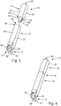
- the cutting tool 13 has a cuboid clamping shank 16 in the example case and cutting means 17 to be brought into contact or in contact with the workpiece to be machined FIG. 3 shown, the clamping shaft 16 has a plurality of components, one of which is a cutting means exhibiting the support member 18 and another is a position setting member 19.
- the groove-like tool holders 14 each have two opposing side walls 20a, 20b and a bottom 21st
- the position setting member 19 has four side surfaces 22, a rear side 23 and an opposite end face 24 due to its cuboid shape.
- the position setting part 19 can be clamped on the clamping means 15 in the associated tool holder 14.
- the clamping means 15 have a first clamping unit 25 assigned to the position specification part 19, with a clamping wedge 26 arranged between a side face 22 serving as a clamping surface and an associated side wall 20a of the tool holder 14, which can be moved toward the bottom 21 of the tool holder 14 via actuating means and away from it is.
- the adjusting means comprise an adjusting screw 27 which is adjustably mounted on a screw carrier 28, wherein when screwing the adjusting screw 27 of the clamping wedge 26 is displaced towards the bottom.
- the clamping wedge 26 presses on the clamping surface of the position specification part 19 and pushes it sideways, whereby the position setting part 19 is clamped.
- the screw carrier 28 also serves as a hold-down and biases the position specification part 19 on the bottom 21 of the tool holder 14.
- FIGS. 3 and 4 illustrated support member 18 is formed longer in the example compared to the position specification part 19.
- the support member 18 has four side surfaces 29, a back 30 and an end face 31.
- a second clamping unit 32 which is constructed in the example identical to the first clamping unit 25 and therefore also a clamping wedge 26, an adjusting screw 27 and a screw carrier 28 has.
- the two clamping units 25, 32 are operable independently of each other, wherein for tool change, only the second clamping unit 32 is actuated, and the position specification part 19 remains clamped on the first clamping unit 25.
- the cutting means 17 comprise, in the example shown, an indexable insert 33, which is received on a plate seat and clamped by means of a fastening screw 34.
- the indexable insert 33 is prism-shaped in the example and has a cutting edge 35 formed by two tapered side edges, which comes into contact with the workpiece to be machined for machining.
- the large-area upper side of the indexable insert 33 forms a rake face 36.
- cooling lubricant For cooling the cutting edge 35 and chip removal is used cooling lubricant, which emerges from the example in the case of several cooling lubricant outlet openings 37 and injects purposefully in the direction of rake face 36.
- a support surface 38 is formed on the position preselecting part 19, which cooperates with a counter support surface 39 formed on the support member 18.
- a support surface 38 and counter support surface 39 are support surface 38 and counter support surface 39 to each other.
- Support surface 38 and counter support surface 39 provide for centering of the support member 18 relative to the stationary remaining position setting part 19th
- the support surface 38 is arranged on the position specification part 19 in the region of the end face 24 thereof, namely on a strip-like support projection 42 projecting forwardly from a front surface section 41 formed at right angles to the side surface 22.
- the support surface 38 is formed as an inclined surface and aligned obliquely to the end face portion 41, wherein the inclined surface in the direction of the side surface 22 to the end face portion 41 springs back.
- the counter-support surface 39 is also formed on the support member 18 in the region of the end face 31.
- the counter support surface 39 is formed as an inclined surface. It is aligned obliquely to an end face portion 43. In the direction of the end face portion 43 to the associated side surface 29 of the support member 18, the counter support surface 39 jumps back.
- the supply of cooling lubricant takes place via the clamping shank 16.
- the clamping shank 16 is penetrated by at least one, in the example, a single coolant lubricant channel 44. Since the clamping shank 16 is formed in two parts with the position setting part 19 and the supporting part 18, there is a need for an environment-sealed transition of the cooling lubricant channel 44 between the position setting part 19 and the supporting part 18.
- the coolant lubricant channel 44 is partially formed on a pipe socket 45 arranged on one of the components, which dips into the other component.
- the pipe socket 45 is in the example shown on the position specification part 19, in particular in the region of the end face 24. Conveniently, the pipe socket 45 is arranged concentrically to a central axis of the position specification part 19.
- the cooling lubricant duct 44 extends, as already mentioned, through the clamping shank 16, that is to say both through the position presetting part 19 as well as through the support member 18.
- the supply of cooling lubricant via a cooling lubricant inlet opening 46, which may be formed either on a side surface 22 of the position specification part 19 or at the rear side 23 thereof.
- the cooling lubricant inlet opening 46 is located on the side surface 22 and the opening on the rear side 23 is closed by means of a closure element, for example a screw.
- the cooling lubricant passage 44 has in the region of the position specification part 19 a branching out of the cooling lubricant inlet opening 46 branch channel, which opens into a particular coaxial with a longitudinal axis 48 of the cutting tool 13 between the rear opening and the pipe socket 45 extending feed channel section 49.
- the coolant lubricant channel 44 is formed by the pipe socket 45.
- the support member 18 extends from the pipe socket 45, starting also suitably coaxially to the longitudinal axis 48 extending Zu Norwaykanalab legislative 50 to the at least one cooling lubricant outlet opening 37 in the region of the cutting means 17th
- the pipe socket 45 is floating while allowing all-round radial and tilting movements relative to the component to which it is arranged, that is, in the example, the position specification part 19.
- bearing means 51 which have a bearing receptacle on the associated component, ie in the example of the position specification part 19, and at least one disposed between an inner wall of the bearing receptacle and a lateral surface 52 of the pipe socket 45 annular bearing element 53 made of elastically yielding material ,
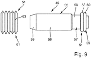
- the pipe socket 45 which could also be referred to as a tubular nozzle member, has a plurality of functional sections with different functions.
- the pipe socket 45 is penetrated over its entire length by a nozzle channel section 54, which, as already mentioned, forms part of the coolant lubricant channel 44.
- the pipe socket 45 has a particular conical mouth portion 55, which on the one hand forms a nozzle effect for cooling lubricant flowing in the nozzle channel portion 54 and on the other facilitates insertion into an associated nozzle receptacle 56 in the support member 18.
- In the axial direction of the mouth portion 55 adjacent to a relatively long central portion 56 which in turn merges into a bearing portion 57 in the axial direction.
- the bearing portion 57 has a diameter smaller than the diameter of the central portion 56 support portion 58 on which the annular bearing member 53 is threaded in the form of an O-ring.
- the carrier region 58 is bounded on the end by axial stop means 59, which are formed, for example, in the form of a stop flange 60 of greater diameter than the diameter of the carrier region 58.
- the annular bearing element 53 that is to say in the example of the O-ring, bears against a stop surface of the stop flange 60 facing the carrier region 58.
- the bearing receptacle on Positionsvorgabeteil 19 a separately formed from the position setting part 19 receiving base 61 which is penetrated by the pipe socket 45 and in turn is received in a trained in Positionsvorgabeteil 19 base bearing 62.
- the receiving base 61 is in FIG. 9 shown by way of example with an annular shape and has an external thread 63 which is screwed with an internal thread (not shown) of the base bearing 62.
- the annular receiving socket 61 and the pipe socket 45 can be introduced as a preassembled module together in the base bearing 62 of the position specification part 19. During pre-assembly of the pipe socket 45 is inserted through the annular receiving socket 61.
- the passage opening (not shown) of the receiving base 61 is conical, whereby the O-ring during insertion, which was previously threaded onto the pipe socket 45 and axially fixed by the stop flange 60, between the lateral surface 52 of the pipe socket 45 and the inner wall the receiving base 61 is located. A further movement of the pipe socket 45 with respect to the receiving base 61 in the axial direction is not possible due to the conical shape of the passage opening of the receiving base 61.
- pre-assembly of the pipe socket 45 is screwed to the receiving base 61 as a unit in the base bearing 62.
- two notches diametrically opposite the longitudinal axis of the nozzle are located in the wall of the receiving base 61, which serve to engage a tool, so that a screwing of the assembly into the base bearing 62 is possible on the receiving base 61.
- the nozzle receptacle 64 is formed coaxially to the longitudinal axis of the cutting tool 13 and forms an extension of the support member 18 formed Zuglasskanalabsacrificings 50.
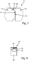
- On the inner wall of the nozzle receptacle 64 is located opposite the wall surface recessed annular groove 65 into which an annular sealing element 66, which is also suitably designed as an O-ring, is inserted.
- annular sealing element 66 acts between the inner wall of the nozzle receptacle 64 and the lateral surface 52 of the pipe socket with a soffit pressure radially inward, prevents the support member 18 from falling out of the tool holder 14 upon release of the clamping and can be damaged. The support member 18 must therefore be pulled out by the user pro active from the tool holder 14.
- the support member 18 After changing the cutting means 17, in particular the turning of the clamped indexable insert 33, the support member 18 is placed back into the associated tool holder 14. At the same time, the pipe socket 45 moves into the associated nozzle receptacle 64 of the supporting part 18. Since the position specification part 19 is exactly aligned, an exact positioning of the support part 18 is achieved by striking the counter support surface 39 against the support surface 38. Jamming during retraction of the Pipe socket 45 in the associated nozzle receptacle 64 is prevented in that the pipe socket 45 is mounted floating on the bearing means 51.
Landscapes
- Engineering & Computer Science (AREA)
- Mechanical Engineering (AREA)
- Cutting Tools, Boring Holders, And Turrets (AREA)
- Auxiliary Devices For Machine Tools (AREA)
Applications Claiming Priority (1)
| Application Number | Priority Date | Filing Date | Title |
|---|---|---|---|
| DE202017000616.2U DE202017000616U1 (de) | 2017-02-06 | 2017-02-06 | Schneidvorrichtung zur spanabhebenden Bearbeitung von Werkstücken |
Publications (2)
| Publication Number | Publication Date |
|---|---|
| EP3357616A1 true EP3357616A1 (fr) | 2018-08-08 |
| EP3357616B1 EP3357616B1 (fr) | 2020-09-16 |
Family
ID=58584135
Family Applications (1)
| Application Number | Title | Priority Date | Filing Date |
|---|---|---|---|
| EP18151896.0A Active EP3357616B1 (fr) | 2017-02-06 | 2018-01-16 | Dispositif de coupe destiné à l'usinage de pièces par enlevement de copeaux |
Country Status (2)
| Country | Link |
|---|---|
| EP (1) | EP3357616B1 (fr) |
| DE (1) | DE202017000616U1 (fr) |
Cited By (1)
| Publication number | Priority date | Publication date | Assignee | Title |
|---|---|---|---|---|
| JP2023108406A (ja) * | 2022-01-25 | 2023-08-04 | 有限会社 大野精機 | 工具アタッチメント及びクーラント噴射システム |
Families Citing this family (2)
| Publication number | Priority date | Publication date | Assignee | Title |
|---|---|---|---|---|
| DE202018100771U1 (de) * | 2018-02-13 | 2018-02-21 | Karl-Heinz Arnold Gmbh | Schneidvorrichtung zur spanabhebenden Bearbeitung von Werkstücken |
| DE102019112337B4 (de) * | 2019-05-10 | 2021-06-17 | W & F Werkzeugtechnik GmbH | Werkzeugaufnahmevorrichtung und Werkzeugmaschine mit einer Werkzeugaufnahmevorrichtung |
Citations (3)
| Publication number | Priority date | Publication date | Assignee | Title |
|---|---|---|---|---|
| US4964764A (en) * | 1988-11-03 | 1990-10-23 | S M P 2 (Societe Anonyme De Droit Francais) | Floating chuck with irrigating flow |
| US20040136793A1 (en) * | 2002-10-25 | 2004-07-15 | Sandvik Ab | Clamping device for tool holder |
| US20150298216A1 (en) * | 2012-10-25 | 2015-10-22 | Utilis Ag | Clamping device with coolant channel, method of producing the clamping device and tool holding plate for a lathe with such a clamping device |
-
2017
- 2017-02-06 DE DE202017000616.2U patent/DE202017000616U1/de active Active
-
2018
- 2018-01-16 EP EP18151896.0A patent/EP3357616B1/fr active Active
Patent Citations (3)
| Publication number | Priority date | Publication date | Assignee | Title |
|---|---|---|---|---|
| US4964764A (en) * | 1988-11-03 | 1990-10-23 | S M P 2 (Societe Anonyme De Droit Francais) | Floating chuck with irrigating flow |
| US20040136793A1 (en) * | 2002-10-25 | 2004-07-15 | Sandvik Ab | Clamping device for tool holder |
| US20150298216A1 (en) * | 2012-10-25 | 2015-10-22 | Utilis Ag | Clamping device with coolant channel, method of producing the clamping device and tool holding plate for a lathe with such a clamping device |
Cited By (1)
| Publication number | Priority date | Publication date | Assignee | Title |
|---|---|---|---|---|
| JP2023108406A (ja) * | 2022-01-25 | 2023-08-04 | 有限会社 大野精機 | 工具アタッチメント及びクーラント噴射システム |
Also Published As
| Publication number | Publication date |
|---|---|
| DE202017000616U1 (de) | 2017-04-03 |
| EP3357616B1 (fr) | 2020-09-16 |
Similar Documents
| Publication | Publication Date | Title |
|---|---|---|
| EP1602426B1 (fr) | Dispositif de serrage pour la fixation avec positionnement précis d'une pince de serrage sur un mandrin | |
| DE102012100976B4 (de) | Einschraubwerkzeug und Werkzeugaufnahme für ein derartiges Einschraubwerkzeug | |
| EP1813381B1 (fr) | Dispositif de serrage doté d'un mandrin pour le serrage fixe d'un élément de serrage | |
| EP3357616A1 (fr) | Dispositif de coupe destiné à l'usinage de pièces par enlevement de copeaux | |
| EP3668668B1 (fr) | Dispositif de porte-outil et procédé pour la fabrication d'un porte-outil | |
| EP2345494A2 (fr) | Mandrin de serrage pour outils | |
| EP2301696A1 (fr) | Interface entre un corps de réception et un insert, l'insert étant notamment développé comme support d'outil ou de pièce à usiner | |
| EP1757392B1 (fr) | Mandrin à diaphragme | |
| DE19835677B4 (de) | Einrichtung zur Zufuhr von Medien an ein Werkzeug | |
| DE19809689A1 (de) | Kupplung zum Anspannen einer Palette o. dgl. | |
| DE102017107488A1 (de) | Spannvorrichtung und Bearbeitungseinheit mit einer derartigen Spannvorrichtung | |
| EP0523404A1 (fr) | Outil à deux arêtes de coupe pour fraiser et alaiser | |
| DE102015121392A1 (de) | Werkzeughalter | |
| EP3459660A1 (fr) | Adaptateur de maintenu d'un outil dans un mandrin à pince de serrage | |
| EP3496896A1 (fr) | Logement d'outil | |
| DE102009050701A1 (de) | Spanneinrichtung | |
| EP2764952A2 (fr) | Porte-outils | |
| EP3524376B1 (fr) | Dispositif de coupe destiné à l'usinage de pièces par enlevement de copeaux | |
| EP1543904A2 (fr) | Porte outil | |
| CH673966A5 (fr) | ||
| EP1593454B1 (fr) | Mandrin à action rapide pour outils, spécialement pour des tarauds | |
| DE3926025C1 (en) | Machine tool precision boring head - has sprung tool support incorporating cooling line | |
| EP1660262A1 (fr) | Point d'assemblage d'un outil | |
| EP2283954B1 (fr) | Plaquette de coupe pour un outil de façonnage et outil de façonnage | |
| DE202018106069U1 (de) | Werkzeughalter, insbesondere Halter für Gewindebohrer |
Legal Events
| Date | Code | Title | Description |
|---|---|---|---|
| PUAI | Public reference made under article 153(3) epc to a published international application that has entered the european phase |
Free format text: ORIGINAL CODE: 0009012 |
|
| STAA | Information on the status of an ep patent application or granted ep patent |
Free format text: STATUS: THE APPLICATION HAS BEEN PUBLISHED |
|
| AK | Designated contracting states |
Kind code of ref document: A1 Designated state(s): AL AT BE BG CH CY CZ DE DK EE ES FI FR GB GR HR HU IE IS IT LI LT LU LV MC MK MT NL NO PL PT RO RS SE SI SK SM TR |
|
| AX | Request for extension of the european patent |
Extension state: BA ME |
|
| STAA | Information on the status of an ep patent application or granted ep patent |
Free format text: STATUS: REQUEST FOR EXAMINATION WAS MADE |
|
| 17P | Request for examination filed |
Effective date: 20190206 |
|
| RBV | Designated contracting states (corrected) |
Designated state(s): AL AT BE BG CH CY CZ DE DK EE ES FI FR GB GR HR HU IE IS IT LI LT LU LV MC MK MT NL NO PL PT RO RS SE SI SK SM TR |
|
| GRAP | Despatch of communication of intention to grant a patent |
Free format text: ORIGINAL CODE: EPIDOSNIGR1 |
|
| STAA | Information on the status of an ep patent application or granted ep patent |
Free format text: STATUS: GRANT OF PATENT IS INTENDED |
|
| INTG | Intention to grant announced |
Effective date: 20200504 |
|
| GRAS | Grant fee paid |
Free format text: ORIGINAL CODE: EPIDOSNIGR3 |
|
| GRAA | (expected) grant |
Free format text: ORIGINAL CODE: 0009210 |
|
| STAA | Information on the status of an ep patent application or granted ep patent |
Free format text: STATUS: THE PATENT HAS BEEN GRANTED |
|
| AK | Designated contracting states |
Kind code of ref document: B1 Designated state(s): AL AT BE BG CH CY CZ DE DK EE ES FI FR GB GR HR HU IE IS IT LI LT LU LV MC MK MT NL NO PL PT RO RS SE SI SK SM TR |
|
| REG | Reference to a national code |
Ref country code: GB Ref legal event code: FG4D Free format text: NOT ENGLISH |
|
| REG | Reference to a national code |
Ref country code: CH Ref legal event code: EP |
|
| REG | Reference to a national code |
Ref country code: DE Ref legal event code: R096 Ref document number: 502018002433 Country of ref document: DE |
|
| REG | Reference to a national code |
Ref country code: IE Ref legal event code: FG4D Free format text: LANGUAGE OF EP DOCUMENT: GERMAN |
|
| REG | Reference to a national code |
Ref country code: AT Ref legal event code: REF Ref document number: 1313697 Country of ref document: AT Kind code of ref document: T Effective date: 20201015 Ref country code: CH Ref legal event code: NV Representative=s name: TROESCH SCHEIDEGGER WERNER AG, CH |
|
| REG | Reference to a national code |
Ref country code: SE Ref legal event code: TRGR |
|
| PG25 | Lapsed in a contracting state [announced via postgrant information from national office to epo] |
Ref country code: NO Free format text: LAPSE BECAUSE OF FAILURE TO SUBMIT A TRANSLATION OF THE DESCRIPTION OR TO PAY THE FEE WITHIN THE PRESCRIBED TIME-LIMIT Effective date: 20201216 Ref country code: FI Free format text: LAPSE BECAUSE OF FAILURE TO SUBMIT A TRANSLATION OF THE DESCRIPTION OR TO PAY THE FEE WITHIN THE PRESCRIBED TIME-LIMIT Effective date: 20200916 Ref country code: BG Free format text: LAPSE BECAUSE OF FAILURE TO SUBMIT A TRANSLATION OF THE DESCRIPTION OR TO PAY THE FEE WITHIN THE PRESCRIBED TIME-LIMIT Effective date: 20201216 Ref country code: HR Free format text: LAPSE BECAUSE OF FAILURE TO SUBMIT A TRANSLATION OF THE DESCRIPTION OR TO PAY THE FEE WITHIN THE PRESCRIBED TIME-LIMIT Effective date: 20200916 Ref country code: GR Free format text: LAPSE BECAUSE OF FAILURE TO SUBMIT A TRANSLATION OF THE DESCRIPTION OR TO PAY THE FEE WITHIN THE PRESCRIBED TIME-LIMIT Effective date: 20201217 |
|
| REG | Reference to a national code |
Ref country code: NL Ref legal event code: MP Effective date: 20200916 |
|
| PG25 | Lapsed in a contracting state [announced via postgrant information from national office to epo] |
Ref country code: RS Free format text: LAPSE BECAUSE OF FAILURE TO SUBMIT A TRANSLATION OF THE DESCRIPTION OR TO PAY THE FEE WITHIN THE PRESCRIBED TIME-LIMIT Effective date: 20200916 Ref country code: LV Free format text: LAPSE BECAUSE OF FAILURE TO SUBMIT A TRANSLATION OF THE DESCRIPTION OR TO PAY THE FEE WITHIN THE PRESCRIBED TIME-LIMIT Effective date: 20200916 |
|
| REG | Reference to a national code |
Ref country code: LT Ref legal event code: MG4D |
|
| PG25 | Lapsed in a contracting state [announced via postgrant information from national office to epo] |
Ref country code: LT Free format text: LAPSE BECAUSE OF FAILURE TO SUBMIT A TRANSLATION OF THE DESCRIPTION OR TO PAY THE FEE WITHIN THE PRESCRIBED TIME-LIMIT Effective date: 20200916 Ref country code: SM Free format text: LAPSE BECAUSE OF FAILURE TO SUBMIT A TRANSLATION OF THE DESCRIPTION OR TO PAY THE FEE WITHIN THE PRESCRIBED TIME-LIMIT Effective date: 20200916 Ref country code: PT Free format text: LAPSE BECAUSE OF FAILURE TO SUBMIT A TRANSLATION OF THE DESCRIPTION OR TO PAY THE FEE WITHIN THE PRESCRIBED TIME-LIMIT Effective date: 20210118 Ref country code: RO Free format text: LAPSE BECAUSE OF FAILURE TO SUBMIT A TRANSLATION OF THE DESCRIPTION OR TO PAY THE FEE WITHIN THE PRESCRIBED TIME-LIMIT Effective date: 20200916 Ref country code: CZ Free format text: LAPSE BECAUSE OF FAILURE TO SUBMIT A TRANSLATION OF THE DESCRIPTION OR TO PAY THE FEE WITHIN THE PRESCRIBED TIME-LIMIT Effective date: 20200916 Ref country code: EE Free format text: LAPSE BECAUSE OF FAILURE TO SUBMIT A TRANSLATION OF THE DESCRIPTION OR TO PAY THE FEE WITHIN THE PRESCRIBED TIME-LIMIT Effective date: 20200916 |
|
| PG25 | Lapsed in a contracting state [announced via postgrant information from national office to epo] |
Ref country code: ES Free format text: LAPSE BECAUSE OF FAILURE TO SUBMIT A TRANSLATION OF THE DESCRIPTION OR TO PAY THE FEE WITHIN THE PRESCRIBED TIME-LIMIT Effective date: 20200916 Ref country code: AL Free format text: LAPSE BECAUSE OF FAILURE TO SUBMIT A TRANSLATION OF THE DESCRIPTION OR TO PAY THE FEE WITHIN THE PRESCRIBED TIME-LIMIT Effective date: 20200916 Ref country code: PL Free format text: LAPSE BECAUSE OF FAILURE TO SUBMIT A TRANSLATION OF THE DESCRIPTION OR TO PAY THE FEE WITHIN THE PRESCRIBED TIME-LIMIT Effective date: 20200916 Ref country code: IS Free format text: LAPSE BECAUSE OF FAILURE TO SUBMIT A TRANSLATION OF THE DESCRIPTION OR TO PAY THE FEE WITHIN THE PRESCRIBED TIME-LIMIT Effective date: 20210116 |
|
| REG | Reference to a national code |
Ref country code: DE Ref legal event code: R097 Ref document number: 502018002433 Country of ref document: DE |
|
| PG25 | Lapsed in a contracting state [announced via postgrant information from national office to epo] |
Ref country code: SK Free format text: LAPSE BECAUSE OF FAILURE TO SUBMIT A TRANSLATION OF THE DESCRIPTION OR TO PAY THE FEE WITHIN THE PRESCRIBED TIME-LIMIT Effective date: 20200916 |
|
| PLBE | No opposition filed within time limit |
Free format text: ORIGINAL CODE: 0009261 |
|
| STAA | Information on the status of an ep patent application or granted ep patent |
Free format text: STATUS: NO OPPOSITION FILED WITHIN TIME LIMIT |
|
| 26N | No opposition filed |
Effective date: 20210617 |
|
| PG25 | Lapsed in a contracting state [announced via postgrant information from national office to epo] |
Ref country code: DK Free format text: LAPSE BECAUSE OF FAILURE TO SUBMIT A TRANSLATION OF THE DESCRIPTION OR TO PAY THE FEE WITHIN THE PRESCRIBED TIME-LIMIT Effective date: 20200916 Ref country code: SI Free format text: LAPSE BECAUSE OF FAILURE TO SUBMIT A TRANSLATION OF THE DESCRIPTION OR TO PAY THE FEE WITHIN THE PRESCRIBED TIME-LIMIT Effective date: 20200916 Ref country code: MC Free format text: LAPSE BECAUSE OF FAILURE TO SUBMIT A TRANSLATION OF THE DESCRIPTION OR TO PAY THE FEE WITHIN THE PRESCRIBED TIME-LIMIT Effective date: 20200916 |
|
| PG25 | Lapsed in a contracting state [announced via postgrant information from national office to epo] |
Ref country code: LU Free format text: LAPSE BECAUSE OF NON-PAYMENT OF DUE FEES Effective date: 20210116 |
|
| REG | Reference to a national code |
Ref country code: BE Ref legal event code: MM Effective date: 20210131 |
|
| PG25 | Lapsed in a contracting state [announced via postgrant information from national office to epo] |
Ref country code: IE Free format text: LAPSE BECAUSE OF NON-PAYMENT OF DUE FEES Effective date: 20210116 |
|
| PG25 | Lapsed in a contracting state [announced via postgrant information from national office to epo] |
Ref country code: BE Free format text: LAPSE BECAUSE OF NON-PAYMENT OF DUE FEES Effective date: 20210131 |
|
| P01 | Opt-out of the competence of the unified patent court (upc) registered |
Effective date: 20230519 |
|
| PG25 | Lapsed in a contracting state [announced via postgrant information from national office to epo] |
Ref country code: NL Free format text: LAPSE BECAUSE OF NON-PAYMENT OF DUE FEES Effective date: 20200923 Ref country code: CY Free format text: LAPSE BECAUSE OF FAILURE TO SUBMIT A TRANSLATION OF THE DESCRIPTION OR TO PAY THE FEE WITHIN THE PRESCRIBED TIME-LIMIT Effective date: 20200916 |
|
| PG25 | Lapsed in a contracting state [announced via postgrant information from national office to epo] |
Ref country code: HU Free format text: LAPSE BECAUSE OF FAILURE TO SUBMIT A TRANSLATION OF THE DESCRIPTION OR TO PAY THE FEE WITHIN THE PRESCRIBED TIME-LIMIT; INVALID AB INITIO Effective date: 20180116 |
|
| PGFP | Annual fee paid to national office [announced via postgrant information from national office to epo] |
Ref country code: AT Payment date: 20240118 Year of fee payment: 7 |
|
| PG25 | Lapsed in a contracting state [announced via postgrant information from national office to epo] |
Ref country code: MK Free format text: LAPSE BECAUSE OF FAILURE TO SUBMIT A TRANSLATION OF THE DESCRIPTION OR TO PAY THE FEE WITHIN THE PRESCRIBED TIME-LIMIT Effective date: 20200916 |
|
| PGFP | Annual fee paid to national office [announced via postgrant information from national office to epo] |
Ref country code: DE Payment date: 20231130 Year of fee payment: 7 Ref country code: GB Payment date: 20240124 Year of fee payment: 7 Ref country code: CH Payment date: 20240202 Year of fee payment: 7 |
|
| PGFP | Annual fee paid to national office [announced via postgrant information from national office to epo] |
Ref country code: SE Payment date: 20240123 Year of fee payment: 7 Ref country code: IT Payment date: 20240131 Year of fee payment: 7 Ref country code: FR Payment date: 20240123 Year of fee payment: 7 |
|
| PG25 | Lapsed in a contracting state [announced via postgrant information from national office to epo] |
Ref country code: TR Free format text: LAPSE BECAUSE OF FAILURE TO SUBMIT A TRANSLATION OF THE DESCRIPTION OR TO PAY THE FEE WITHIN THE PRESCRIBED TIME-LIMIT Effective date: 20200916 |