EP3357284B1 - Verfahren und systeme für uplink-leistungzuweisungsverfahren in mehrträger-szenarien - Google Patents
Verfahren und systeme für uplink-leistungzuweisungsverfahren in mehrträger-szenarien Download PDFInfo
- Publication number
- EP3357284B1 EP3357284B1 EP16778461.0A EP16778461A EP3357284B1 EP 3357284 B1 EP3357284 B1 EP 3357284B1 EP 16778461 A EP16778461 A EP 16778461A EP 3357284 B1 EP3357284 B1 EP 3357284B1
- Authority
- EP
- European Patent Office
- Prior art keywords
- power allocation
- user equipment
- uplink
- power
- carrier
- Prior art date
- Legal status (The legal status is an assumption and is not a legal conclusion. Google has not performed a legal analysis and makes no representation as to the accuracy of the status listed.)
- Not-in-force
Links
- 238000000034 method Methods 0.000 title claims description 109
- 239000000969 carrier Substances 0.000 claims description 41
- 238000003860 storage Methods 0.000 claims description 24
- 238000004891 communication Methods 0.000 claims description 19
- 230000009977 dual effect Effects 0.000 claims description 8
- 230000003287 optical effect Effects 0.000 claims description 5
- 238000004590 computer program Methods 0.000 claims description 4
- 230000015654 memory Effects 0.000 description 15
- 230000005540 biological transmission Effects 0.000 description 11
- 230000006870 function Effects 0.000 description 10
- 238000013459 approach Methods 0.000 description 8
- 230000008859 change Effects 0.000 description 6
- 230000011664 signaling Effects 0.000 description 6
- 230000008901 benefit Effects 0.000 description 5
- 238000001228 spectrum Methods 0.000 description 4
- 230000006399 behavior Effects 0.000 description 3
- 238000004364 calculation method Methods 0.000 description 3
- 230000000694 effects Effects 0.000 description 3
- 238000010187 selection method Methods 0.000 description 3
- 238000004422 calculation algorithm Methods 0.000 description 2
- 238000005516 engineering process Methods 0.000 description 2
- 230000007774 longterm Effects 0.000 description 2
- 230000007246 mechanism Effects 0.000 description 2
- 230000002085 persistent effect Effects 0.000 description 2
- 238000012545 processing Methods 0.000 description 2
- 239000007787 solid Substances 0.000 description 2
- 238000012360 testing method Methods 0.000 description 2
- 230000003044 adaptive effect Effects 0.000 description 1
- 230000002776 aggregation Effects 0.000 description 1
- 238000004220 aggregation Methods 0.000 description 1
- 230000009286 beneficial effect Effects 0.000 description 1
- 238000010276 construction Methods 0.000 description 1
- 238000007796 conventional method Methods 0.000 description 1
- 230000008878 coupling Effects 0.000 description 1
- 238000010168 coupling process Methods 0.000 description 1
- 238000005859 coupling reaction Methods 0.000 description 1
- 230000001419 dependent effect Effects 0.000 description 1
- 238000005562 fading Methods 0.000 description 1
- 238000009313 farming Methods 0.000 description 1
- 230000005012 migration Effects 0.000 description 1
- 238000013508 migration Methods 0.000 description 1
- 238000012986 modification Methods 0.000 description 1
- 230000004048 modification Effects 0.000 description 1
- 238000005457 optimization Methods 0.000 description 1
- 230000000737 periodic effect Effects 0.000 description 1
- 230000003068 static effect Effects 0.000 description 1
- 238000012956 testing procedure Methods 0.000 description 1
- 230000001052 transient effect Effects 0.000 description 1
Images


Classifications
-
- H—ELECTRICITY
- H04—ELECTRIC COMMUNICATION TECHNIQUE
- H04W—WIRELESS COMMUNICATION NETWORKS
- H04W52/00—Power management, e.g. TPC [Transmission Power Control], power saving or power classes
- H04W52/04—TPC
- H04W52/06—TPC algorithms
- H04W52/14—Separate analysis of uplink or downlink
- H04W52/146—Uplink power control
-
- H—ELECTRICITY
- H04—ELECTRIC COMMUNICATION TECHNIQUE
- H04W—WIRELESS COMMUNICATION NETWORKS
- H04W52/00—Power management, e.g. TPC [Transmission Power Control], power saving or power classes
- H04W52/04—TPC
- H04W52/18—TPC being performed according to specific parameters
- H04W52/24—TPC being performed according to specific parameters using SIR [Signal to Interference Ratio] or other wireless path parameters
- H04W52/241—TPC being performed according to specific parameters using SIR [Signal to Interference Ratio] or other wireless path parameters taking into account channel quality metrics, e.g. SIR, SNR, CIR, Eb/lo
-
- H—ELECTRICITY
- H04—ELECTRIC COMMUNICATION TECHNIQUE
- H04W—WIRELESS COMMUNICATION NETWORKS
- H04W52/00—Power management, e.g. TPC [Transmission Power Control], power saving or power classes
- H04W52/04—TPC
- H04W52/30—TPC using constraints in the total amount of available transmission power
- H04W52/34—TPC management, i.e. sharing limited amount of power among users or channels or data types, e.g. cell loading
-
- H—ELECTRICITY
- H04—ELECTRIC COMMUNICATION TECHNIQUE
- H04W—WIRELESS COMMUNICATION NETWORKS
- H04W72/00—Local resource management
- H04W72/04—Wireless resource allocation
- H04W72/044—Wireless resource allocation based on the type of the allocated resource
- H04W72/0453—Resources in frequency domain, e.g. a carrier in FDMA
-
- H—ELECTRICITY
- H04—ELECTRIC COMMUNICATION TECHNIQUE
- H04W—WIRELESS COMMUNICATION NETWORKS
- H04W72/00—Local resource management
- H04W72/04—Wireless resource allocation
- H04W72/044—Wireless resource allocation based on the type of the allocated resource
- H04W72/0473—Wireless resource allocation based on the type of the allocated resource the resource being transmission power
-
- H—ELECTRICITY
- H04—ELECTRIC COMMUNICATION TECHNIQUE
- H04W—WIRELESS COMMUNICATION NETWORKS
- H04W72/00—Local resource management
- H04W72/20—Control channels or signalling for resource management
- H04W72/23—Control channels or signalling for resource management in the downlink direction of a wireless link, i.e. towards a terminal
-
- H—ELECTRICITY
- H04—ELECTRIC COMMUNICATION TECHNIQUE
- H04W—WIRELESS COMMUNICATION NETWORKS
- H04W76/00—Connection management
- H04W76/20—Manipulation of established connections
- H04W76/27—Transitions between radio resource control [RRC] states
-
- H—ELECTRICITY
- H04—ELECTRIC COMMUNICATION TECHNIQUE
- H04W—WIRELESS COMMUNICATION NETWORKS
- H04W88/00—Devices specially adapted for wireless communication networks, e.g. terminals, base stations or access point devices
- H04W88/02—Terminal devices
Definitions
- the present invention generally relates to power allocation and, more specifically, to uplink power allocation in user equipments.
- WCDMA wide band code division multiple access
- HSPA high speed packet access
- Multi-carrier support has been introduced into HSPA specifications over several releases and currently supports up to eight downlink carriers and up to two uplink carriers. While downlink carriers are allowed to be non-contiguous (multi-band operation), the uplink carriers need to be adjacent (single-band operation).
- HSPA uplink multicarrier referred to as dual-cell (DC) HSUPA, was introduced in Rel-9 of the Third Generation Partnership Project (3GPP) specifications.
- Single-band operation in the uplink typically allows for the use of one power amplifier (PA) for both carriers, which makes the implementation simpler and cheaper.
- PA power amplifier
- dual-band capability is attractive to operators that use a fragmented spectrum. Dual-band may become even more useful in the future due to spectrum re-farming to other technologies, e.g., long term evolution (LTE).
- LTE long term evolution
- a typical operator may have one carrier in a low band, e.g., U900, and one or two carriers in a high-band, e.g., U2100. Hence being able to efficiently operate two carriers in different bands is expected to be useful for providing a successful MBB experience for HSPA in the future.
- WO 2007/066907 A1 discloses a method for adaptive transmit power allocation in a multiuser OFDM system, the method comprising: obtaining a channel gain for a predetermined bit period for each user at a predetermined time, and allocating all of the available sub carriers to a user farthest separated among a plurality of users having a good channel gain; comparing a channel gain of the user allocated the sub carriers with an initial threshold value; allocating transmit power uniformly if the channel gain is larger than the initial threshold value, or allocating the transmit power non-uniformly if the channel gain is smaller than the initial threshold value.
- WO2015/116866 discloses the selection between a power allocation technique with priority and one without priority.
- DB-DC-HSUPA dual-band dual-cell HSUPA
- radio frequency (RF) conformance requirements need to be updated with values specifically relevant to each combination.
- RF radio frequency
- RRM radio resource management
- uplink (UL) transmission (Tx) power allocation and enhanced dedicated channel transport format combination (E-TFC) selection are not currently optimal for dual-band operation.
- Embodiments allow for implementing different uplink power allocation techniques for wireless devices which use dual-band dual-cell high speed uplink packet access (DB-DC-HSUPA) to improve power usage as compared to conventional techniques.
- DB-DC-HSUPA dual-band dual-cell high speed uplink packet access
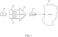
- Figure 1 illustrates a dual-band dual-cell high speed uplink packet access (DB-DC-HSUPA) for which power allocation techniques described herein can be implemented.
- the user equipment (UE) 100 communicates uplink data to a NodeB 102 which in turn is in communications with a network 104. While a NodeB 102 is shown and described in Figure 1 , it is to be understood that in some networks other types of nodes which perform similar functions to a NodeB could be used, e.g., an eNB or another form of base station, in support of embodiments described herein.
- the uplink communication from the UE 100 to the NodeB 102 is shown as an HSUPA communication 106 which includes a first carrier 108 using a frequency band X and a second carrier 110 using a second frequency band Y, where the frequency bands X and Y are operating in different frequency ranges.
- the frequency bands X and Y may be contiguous or non-contiguous. Power allocation techniques are now described beginning with power allocation for a for single-band dual-cell high speed uplink packet access (DC-HSUPA) prior to describing embodiments for dual band in which various power allocation techniques can be used.
- DC-HSUPA single-band dual-cell high speed uplink packet access
- This power allocation technique is referred to herein as the "parallel split" power allocation technique.
- the parallel split power allocation technique described above with respect to Equation (1) will sometimes be suboptimal for certain dual band scenarios.
- the pathloss difference between different bands can be significant, for example, in the order of 10 dB.
- the same number of bits cost less power to send on the low frequency, e.g., U900, carrier than on the high frequency, e.g., U2100, carrier.
- the parallel split power allocation scheme of Equation (1) which can allocate more of the power to the high frequency carrier, thus can lead to unnecessarily expensive bits in terms of UE transmit power.
- the aim with this power allocation scheme is to prioritize the best carrier (i.e., the carrier with lowest DPCCH power). Power is allocated in a sequential manner, where the best carrier is first allocated power up to what the serving grant allows, and then any remaining power is given to the secondary carrier taking the serving grant into consideration.
- the best carrier i.e., the carrier with lowest DPCCH power.
- Figure 2 illustrates some of the effects of the parallel split power allocation and the power sensitive (or greedy filling) power allocation scheme with respect to transmission power when operating in a dual-band dual-cell mode on the UE 100.
- a UE using the parallel split power allocation scheme 200 can transmit on a low frequency carrier 202 using a power amount represented by Uplink T x P A 204 and can transmit on a high frequency carrier 206 using a power amount represented by Uplink T x P B 208.
- the Uplink T x P B can be greater than Uplink T x P A as shown in block 210 for the reasons mentioned previously.
- a UE using the power sensitive power allocation technique 212 can transmit on a low frequency carrier 202 using a power amount represented by Uplink T x P C 214 and can transmit on a high frequency carrier 206 using a power represented by Uplink T x P D 216.
- the Uplink T x P C can be greater than Uplink T x P D as shown in block 218.
- the power sensitive technique will potentially more efficiently allocate power to the bits being transmitted.
- a UE can be configured to use either of the two (or more) different power allocation techniques. This means that a decision has to be made, e.g., either by the UE or by the network regarding which of the power allocations to use for any given transmission.
- the UE has better knowledge than the network about the power situation (i.e., available remaining power) at the UE side and can therefore, in general, make faster and better decisions.
- the network is the node aware of the overall network load situation and is therefore best suited for handling the load balancing.
- various combinations of nodes e.g., the network, NodeB and the UE
- various combinations of nodes can have various contributions to the power allocation technique selection mechanism.
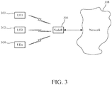
- a framework that encompasses both the legacy parallel split power technique and the power sensitive (greedy filling) power allocation technique with network controlled operation. This enables the following: (1) having the ability to choose between the parallel and the greedy filling (GF) techniques; and (2) when the network uses the GF, having the ability to limit the application of GF to a subset of UEs - such as those power limited UEs that would benefit most from GF.
- GF greedy filling
- a subset of the UEs can be the subset of UEs that would benefit, in this example, from using the GF power allocation technique, whereas another UE, e.g., UEn 304, may benefit from using the parallel split power allocation technique.
- the UE does hypothesis testing to maximize a certain criterion, e.g., total throughput, as a mechanism for selecting which power allocation technique to apply to its pending transmission.
- a certain criterion e.g., total throughput
- the UE performs two different power allocation and E-TFC selection calculations, one per power allocation scheme, and then chooses the alternative that maximizes the criterion function.
- E-TFC selection is described in more detail below.
- additional constraints can be added that restrict which hypotheses are allowed. For example, additional constraints can be configured that would force the UE to use one or the other of the two power allocation techniques.
- Examples include, but are not restricted to: (1) a network configured parameter that indicates whether the parallel power allocation technique, the GF power allocation technique, or both techniques should be used in the E-TFC selection procedure; and (2) the choice of which techniques to include in the hypothesis testing can more generally be a function of one or several input parameters. Specific embodiments illustrating the use of such parameters are described below.
- these input parameters include, but are not limited to: (1) a function of the difference in DPCCH power level for the two carriers; (2) if the difference is large enough (above a threshold), then use the GF, otherwise use the parallel split power technique; (3) and/or a function of absolute DPCCH power level for one or both carriers; and/or a function of difference in SG between the carriers; (4) and/or a function of absolute SGs for the two carriers; (5) and/or a function of power status at the UE side (e.g., GF when power limited); (6) and/or a function of measured downlink quality for the downlink (DL) carriers corresponding to the uplink (UL) carriers.
- a function of the difference in DPCCH power level for the two carriers include, but are not limited to: (1) a function of the difference in DPCCH power level for the two carriers; (2) if the difference is large enough (above a threshold), then use the GF, otherwise use the parallel split power technique; (3) and/or a function of absolute D
- the UE can apply the GF technique and otherwise the UE can apply the parallel split power technique.
- CPICH common pilot channel
- SNR signal-to-noise ratio
- SINR signal-to-interference-and-noise ratio
- the SG can be a factor for determining which power allocation technique to use. For example, when the UE is operating in DB-DC-HSUPA mode, and the secondary carrier is Activated, then if the serving grant on the low band carrier (e.g., U900) SG I is below a threshold ⁇ then the UE shall use the greedy filling technique, otherwise the UE uses the parallel split power technique.
- the serving grant on the low band carrier e.g., U900
- the UE shall use the greedy filling technique, otherwise the UE uses the parallel split power technique.
- the UE uses the parallel split power technique.
- the following logic can be implemented in the UE to select a power allocation scheme.
- the threshold ⁇ can be hardcoded into the specifications, be a dynamic L1 parameter, a semi-static radio resource control (RRC), or a Node B application part (NBAP)/radio network subsystem application part (RNSAP) parameter.
- RRC radio resource control
- NBAP Node B application part
- RNSAP radio network subsystem application part
- ⁇ represents an example of the constraints or parameters mentioned above by way of which the network can influence the UE's selection of the power allocation technique.
- the amount of power available can also be a factor for determining the choice of power allocation technique to be used for UEs. For example, when a UE is operating in DB-DC-HSUPA mode, and the secondary carrier is Activated then if serving grant on the low band carrier (e.g., U900) SG I is below a threshold ⁇ and the UE is power limited, then the UE shall use the greedy filling algorithm, otherwise use the parallel split power technique.
- the low band carrier e.g., U900
- Uplink power limited can be defined in different ways.
- One example could be that the UE, even when transmitting at its maximum allowed power using the parallel power split technique, does not have enough remaining power to be able to transmit all E-TFCs accordingly to one or both of the serving grants on each carrier.
- certain E-TFCs are restricted (as defined by 3GPP 25.133) on one or both carriers.
- Such a power limitation might occur regardless of whether the UE uses a single PA or a dual PA architecture.
- the threshold ⁇ can be hardcoded into the specifications, be a dynamic L1 parameter, or a semi-static RRC, NBAP/RNSAP parameter.
- a UE that is power limited when trying to apply the parallel split power technique may still be power limited when it applies the GF power technique.
- the GF scheme will be more efficient in terms of the amount of bits sent.
- the methods described above for selecting a power allocation technique can be controlled in different ways. More specifically, how to set parameters to control selection of the techniques and how to handle communications between the UE(s) and the network can be done differently. Some examples are now described.
- parameters for controlling the operation of this approach can be hardcoded into the spec, be a dynamic L1 parameter, a semi-static RRC, a NBAP/RNSAP parameter, or a combination thereof.
- the network may indicate to the UE via RRC signalling and the Node B via NBAP signalling to apply either the parallel split power allocation technique or the greedy filling power allocation technique during setting up or reconfiguration.
- the network can dynamically change the value of certain parameters by means of L1 orders (e.g., shared control channel for HS-DSCH (HS-SCCH) orders).
- the UE autonomously decides how to set certain parameters, e.g., whether to use the GF technique or the parallel split power technique.
- the UE may indicate to the network, e.g., via RRC or mobility control information (MCI) that certain criteria used to select a different power allocation scheme were reached and thus request the network to change some of the parameters, for example, to change the power allocation technique.
- MCI mobility control information
- the UE could be beneficial for the UE to dynamically notify the network about its actions. For example, there could be a L1 indication sent from the UE to the network regarding whether the GF or the parallel split algorithm is employed. Even if dynamic L1 signaling is deemed too costly or complex, the UE can still indicate to the network, e.g., via RRC or MCI, the power scheme currently in use to provide awareness of the technique to the network. If this kind of semi-dynamic signaling is used, it may be useful to impose some restrictions on how often the UE is allowed to change power selection techniques to avoid ping-pong effects. Hence, changing the power technique too often may, in some scenarios, be undesirable.
- the enhanced dedicated channel transport format combination (E-TFC) selection procedure consists of power allocation (described above) and data allocation.
- the current DC-HSUPA data allocation scheme is sequential starting from the secondary carrier. That is, given the result of the power allocation scheme, data is first allocated to the secondary carrier and thereafter to the primary carrier.
- the power sensitive scheme or greedy filling technique prioritizes the best carrier, it can be useful when using that power allocation technique to change the data allocation scheme and first allocate data to the best carrier and thereafter to the remaining carrier.
- non-scheduled data is always transmitted on the primary carrier.
- the data allocation scheme can be changed to always map non-scheduled data to the best carrier.
- the UE can decide if retransmission should occur or if a new transmission window for data is to be used.
- Changing the E-TFC selection option may create (undesirable) transient behaviors in the system before reaching a 'stable' mode of operation. If the network is in control of operation, then the network can also ensure that changes are done such that a robust and well-behaved network is maintained. If some of the choices are left for the UE to take, it may be useful to impose restrictions on the UE: For example, according to an embodiment, the UE is only allowed to change power selection technique behavior once every x transmission time interval (TTI), or within a restricted periodic time period, where x is an integer. Other selection behavior can also be used as desired.
- TTI transmission time interval
- Changing the E-TFC selection technique may also affect other components in the E-TFC selection procedure, e.g., retransmissions.
- retransmissions could be handled as in the current spec (3GPP TS 25.133, 25.321) today, i.e., retransmissions always get priority to be allocated power so when the power splitting is done the same way regardless of when the GF or parallel split power technique is used, see, for example, the reference text produced below in the next paragraph from 3GPP TS 25.133.
- the UE when the UE has more than one Activated Uplink Frequency and one retransmission is required in one Activated Uplink Frequency, the UE shall estimate the normalized remaining power margin available for E-TFC selection using the power allocated to the Activated Uplink Frequency for which a retransmission is required Pallocated,x and on the power allocated to the Activated Uplink Frequency for which no retransmission is required Pallocated,y defined by Equations (4) and (5).
- various optimizations can be envisioned since there might be situations in which the network performance could be improved if the UE 'ignores' a retransmission and prioritizes according to the currently employed power allocation scheme. For example, it may be desirable to ignore a retransmission if it becomes significantly more expensive (in terms of power) to send the retransmission on the lower quality carrier than sending new data on the best carrier, or if the UE has become power limited and has significantly too little power to accommodate the retransmission on the worse carrier (in which case it is expected that the retransmission will trigger yet another retransmission).
- Embodiments addressed herein are described in the context of DB-DC-HSUPA, where significantly different pathloss characteristics between the two carriers can occur (e.g., the U900 and U2100 bands).
- the solutions can equally well be applied to the DC-HSUPA case (i.e., when both carriers are in the same frequency band).
- one of the antennas or PA if different PAs are used for the different carriers
- shadowing or small-scale fading can be different for the two carriers.
- the embodiments can also be generalized, for example as shown in the embodiment of Figure 4 .
- a method for controlling uplink (UL) power allocation in a user equipment (UE) operating in a communication network includes: at step 400, selecting between at least a first UL power allocation technique and a second power allocation technique for use in the UE; and at step 402, using the selected power allocation technique in the UE to transmit uplink data by allocating transmit power between at least two carriers on which the uplink data is transmitted.
- Figure 5 illustrates a wireless network comprising a more detailed view of a network 512, a network node 514, e.g., a NodeB or a base station, and a wireless device 502, e.g., a UE, in which the various embodiments described above can be implemented.
- Figure 5 only depicts network 512, network nodes 514 and 522, and the wireless device 502.
- Network node 514 includes a processor 516, storage 518, e.g., a memory, a communications interface 520, and antenna 524.
- the wireless device 502 includes a processor 506, storage 504, e.g., a memory, a communications interface 508 and an antenna 510.
- the wireless network may comprise any number of wired or wireless networks, network nodes, base stations, controllers, wireless devices, relay stations, and/or any other components that may facilitate or participate in the communication of data and/or signals whether via wired or wireless connections in support of embodiments described herein associated with uplink power allocation techniques.
- the network 512 may include one or more IP networks, public switched telephone networks (PSTNs), packet data networks, optical networks, wide area networks (WANs), local area networks (LANs), wireless local area networks (WLANs), wired networks, wireless networks, metropolitan area networks, and other networks to enable communication between devices.
- PSTNs public switched telephone networks
- WANs wide area networks
- LANs local area networks
- WLANs wireless local area networks
- wired networks wireless networks, metropolitan area networks, and other networks to enable communication between devices.
- the network node 514 includes a processor 516, storage 518, a communications interface 520, and antenna 524. These components are depicted as single boxes located within a single larger box. In practice however, a network node may comprise multiple different physical components that make up a single illustrated component (e.g., communication interface 520 may include terminals for coupling wires for a wired connection and a radio transceiver for a wireless connection). As another example, network node 514 may be a virtual network node in which multiple different, physically separate components interact to provide the functionality of network node 515 (e.g., processor 502 may include three separate processors located in three separate enclosures, where each processor is responsible for a different function for a particular instance of network node 514).
- processor 502 may include three separate processors located in three separate enclosures, where each processor is responsible for a different function for a particular instance of network node 514).
- network node 514 may be composed of multiple physically separate components (e.g., a NodeB component and a radio network controller (RNC) component, a base transceiver station (BTS) component and a base station controller (BSC) component, etc.), which may each have their own respective processor, storage, and interface components.
- RNC radio network controller
- BTS base transceiver station
- BSC base station controller
- one or more of the separate components may be shared among several network nodes.
- a single RNC may control multiple NodeBs.
- each unique NodeB and BSC pair may be a separate network node.
- network node 514 may be configured to support multiple radio access technologies (RATs).
- RATs radio access technologies
- some components may be duplicated (e.g., separate storage 516 for the different RATs) and some components may be reused (e.g., the same antenna 524 may be shared by the RATs).
- Processor 518 may be a combination of one or more of a microprocessor, controller, microcontroller, central processing unit, digital signal processor, application specific integrated circuit, field programmable gate array, or any other suitable computing device, resource, or combination of hardware, software and/or encoded logic operable to provide, either alone or in conjunction with other network node 514 components, such as storage 516, network node 514 functionality.
- processor 518 may execute instructions stored in storage 516.
- Such functionality may include providing various wireless features discussed herein to wireless devices, such as wireless device 502, including any of the features or benefits disclosed herein.
- Storage 516 may include any form of volatile or non-volatile computer readable memory including, without limitation, persistent storage, solid state memory, remotely mounted memory, magnetic media, optical media, random access memory (RAM), read-only memory (ROM), removable media, or any other suitable local or remote memory component.
- Storage 518 may also store any suitable instructions, data or information, including software and encoded logic, utilized by network node 514. Storage 516 may be used to store any calculations made by processor 518 and/or any data received via interface 520.
- Network node 514 also includes interface 520 which may be used in the wired or wireless communication of signaling and/or data between network node 514, network 512, and/or wireless device 502.
- interface 520 may perform any formatting, coding, or translating that may be needed to allow network node 514 to send and receive data from network 512 over a wired connection.
- Interface 520 may also include a radio transmitter and/or receiver that may be coupled to or a part of antenna 524.
- the radio may receive digital data that is to be sent out to other network nodes or wireless devices via a wireless connection.
- the radio may convert the digital data into a radio signal having the appropriate channel and bandwidth parameters.
- the radio signal may then be transmitted via antenna 524 to the appropriate recipient (e.g., wireless device 502).
- Antenna 524 may be any type of antenna capable of transmitting and receiving data and/or signals wirelessly.
- antenna 524 may comprise one or more omni-directional, sector or panel antennas operable to transmit/receive radio signals between, for example, 2 GHz and 66 GHz.
- An omni-directional antenna may be used to transmit/receive radio signals in any direction
- a sector antenna may be used to transmit/receive radio signals from devices within a particular area
- a panel antenna may be a line of sight antenna used to transmit/receive radio signals in a relatively straight line.
- Wireless device 502 may be any type of wireless endpoint, mobile station, mobile phone, wireless local loop phone, smartphone, user equipment, desktop computer, PDA, cell phone, tablet, laptop, VoIP phone or handset, which is able to wirelessly send and receive data and/or signals to and from a network node, such as network nodes 514 and 522 and/or other wireless devices 502.
- Wireless device 502 includes a processor 506, storage 504, e.g., memory, a communications interface 508, and an antenna 510.
- the components of the wireless device 502 are depicted as single boxes located within a single larger box, however in practice a wireless device may comprises multiple different physical components that make up a single illustrated component (e.g., storage 504 may comprise multiple discrete microchips, each microchip representing a portion of the total storage capacity).
- Processor 506 may be a combination of one or more of a microprocessor, controller, microcontroller, central processing unit, digital signal processor, application specific integrated circuit, field programmable gate array, or any other suitable computing device, resource, or combination of hardware, software and/or encoded logic operable to provide, either alone or in combination with other wireless device 502 components, such as storage 504, wireless device 502 functionality.
- Such functionality may include providing various wireless features discussed herein, including any of the features or benefits disclosed herein.
- Storage 504 may be any form of volatile or non-volatile memory including, without limitation, persistent storage, solid state memory, remotely mounted memory, magnetic media, optical media, random access memory (RAM), read-only memory (ROM), removable media, or any other suitable local or remote memory component.
- Storage 504 may store any suitable data, instructions, or information, including software and encoded logic, utilized by wireless device 502.
- Storage 504 may be used to store any calculations made by processor 506 and/or any data received via interface 508.
- Interface 508 may be used in the wireless communication of signaling and/or data between wireless device 502 and network nodes 514 and 522.
- interface 508 may perform any formatting, coding, or translating that may be needed to allow wireless device 502 to send and receive data from network node 514 over a wireless connection.
- Interface 508 may also include a radio transmitter and/or receiver that may be coupled to or a part of antenna 510.
- the radio may receive digital data that is to be sent out to network node 514 via a wireless connection.
- the radio may convert the digital data into a radio signal having the appropriate channel and bandwidth parameters.
- the radio signal may then be transmitted via antenna 510 to network node 514.
- Antenna 510 may be any type of antenna capable of transmitting and receiving data and/or signals wirelessly.
- antenna 510 may comprise one or more omni-directional, sector or panel antennas operable to transmit/receive radio signals between 2 GHz and 66 GHz.
- antenna 510 may be considered a part of interface 508 to the extent that a wireless signal is being used.
- Embodiments allow for the combination of the parallel split power allocation technique, E-TFC selection scheme and the power sensitive power allocation technique for DB-DC-HSUPA operation. This provides network control of when to operate one or the other scheme and to facilitate a flexible migration path for implementing DB-DC-HSUPA. Additionally, embodiments allow for the use of different power allocation techniques which best suit the UE power, while allowing the network to provide control to achieve load balancing.
- the embodiments may take the form of an entirely hardware embodiment or an embodiment combining hardware and software aspects. Further, the embodiments, e.g., implementing the desired uplink power allocation technique, can be implemented using a computer program product stored on a computer-readable storage medium having computer-readable instructions embodied in the medium. Any suitable computer-readable medium may be utilized, including RAM, hard disks, CD-ROMs, digital versatile disc (DVD), optical storage devices, or magnetic storage devices such as floppy disk or magnetic tape. Other non-limiting examples of computer-readable media include flash-type memories or other known memories.
Landscapes
- Engineering & Computer Science (AREA)
- Computer Networks & Wireless Communication (AREA)
- Signal Processing (AREA)
- Quality & Reliability (AREA)
- Mobile Radio Communication Systems (AREA)
Claims (12)
- Verfahren zur Steuerung von Uplink-Leistungszuweisung in einer Benutzereinrichtung (502), die in einem Kommunikationsnetzwerk tätig ist, wobei das Verfahren umfasst:Auswählen (400) zwischen mindestens einer ersten Uplink-Leistungszuweisungstechnik und einer zweiten Leistungszuweisungstechnik zur Verwendung in der Benutzereinrichtung (502); undVerwenden (402) der ausgewählten Leistungszuweisungstechnik in der Benutzereinrichtung (502) zum Senden von Uplink-Daten durch Zuweisen von Sendeleistung zwischen mindestens zwei Trägern, auf welchen die Uplink-Daten gesendet werden,wobei die erste Uplink-Leistungszuweisungstechnik eine parallele geteilte Leistungszuweisung ist, die basierend auf der Qualität eines dedizierten physikalischen Steuerkanals und einer Versorgungsgenehmigung für jeden Träger bestimmt wird, undwobei die zweite Uplink-Leistungszuweisungstechnik ein leistungsempfindliches Leistungszuweisungsschema ist, wobei Leistung der Reihe nach vom besten bis zum schlechtesten Träger bis zu einer Versorgungsgenehmigung für jeden Träger zugewiesen wird.
- Benutzereinrichtung (502) in einem Kommunikationsnetzwerk, in welcher Uplink-Leistungszuweisung gesteuert wird, wobei die Benutzereinrichtung (502) umfasst:einen Prozessor (506), der zum Auswählen zwischen mindestens einer ersten Uplink-Leistungszuweisungstechnik und einer zweiten Uplink-Leistungszuweisungstechnik zur Verwendung in der Benutzereinrichtung (502) konfiguriert ist; undwobei der Prozessor (506) so konfiguriert ist, dass er die ausgewählte Uplink-Leistungszuweisungstechnik in der Benutzereinrichtung (502) zum Senden von Uplink-Daten durch Zuweisen von Sendeleistung zwischen mindestens zwei Trägern verwendet, auf welchen die Uplink-Daten gesendet werden,wobei die erste Uplink-Leistungszuweisungstechnik eine parallele geteilte Leistungszuweisung ist, die basierend auf der Qualität eines dedizierten physikalischen Steuerkanals und einer Versorgungsgenehmigung für jeden Träger bestimmt wird, undwobei die zweite Uplink-Leistungszuweisungstechnik ein leistungsempfindliches Leistungszuweisungsschema ist, wobei Leistung der Reihe nach vom besten bis zum schlechtesten Träger bis zu einer Versorgungsgenehmigung für jeden Träger zugewiesen wird.
- Benutzereinrichtung (502) nach Anspruch 2, wobei ein Datenzuweisungsschema wenigstens zum Teil basierend auf der ausgewählten Uplink-Leistungszuweisungstechnik ausgewählt wird.
- Benutzereinrichtung (502) nach einem der Ansprüche 2 und 3, wobei die zu verwendende Uplink-Leistungszuweisungstechnik der Benutzereinrichtung (502) durch das Kommunikationsnetzwerk angezeigt werden kann.
- Benutzereinrichtung (502) nach einem der Ansprüche 2 bis 4, wobei die Auswahl der Uplink-Leistungszuweisungstechnik an der Benutzereinrichtung (502) stattfindet.
- Benutzereinrichtung (502) nach einem der Ansprüche 2 bis 4, wobei die Auswahl der Uplink-Leistungszuweisungstechnik wenigstens zum Teil basiert auf mindestens einem von einem netzwerkkonfigurierten Parameter; einer Funktion einer Differenz eines Leistungspegels eines dedizierten physikalischen Steuerkanals zwischen zwei Trägern; einer Funktion eines absoluten Leistungspegels für einen oder beide Träger; einer Funktion einer Differenz einer Versorgungsgenehmigung zwischen den beiden Trägern; einer Funktion von absoluten Versorgungsgenehmigungen für die beiden Träger; einer Funktion eines Leistungsstatus an der Benutzereinrichtung (502); und einer Funktion einer gemessenen Downlink-Qualität für Downlink-Träger, welche Uplink-Trägern entsprechen.
- Benutzereinrichtung (502) nach einem der Ansprüche 2 bis 4, wobei, wenn die Benutzereinrichtung (502) in einem Dualband-Dualzell-Hochgeschwindigkeits-Uplink-Paketzugriffsmodus funktioniert und ein zweiter Träger aktiv ist, die zweite Uplink-Leistungszuweisungstechnik ausgewählt wird, wenn eine Versorgungsgenehmigung unter einer vorbestimmten Schwelle ist, und andernfalls die erste Uplink-Leistungszuweisungstechnik ausgewählt wird.
- Benutzereinrichtung (502) nach Anspruch 7, wobei die vorbestimmte Schwelle durch das Netzwerk bestimmt und über mindestens eine Funkressourcensteuernachricht an die Benutzereinrichtung (502) kommuniziert wird.
- Benutzereinrichtung (502) nach einem der Ansprüche 2 bis 4, wobei, wenn die Benutzereinrichtung (502) in einem Dualband-Dualzell-Hochgeschwindigkeits-Uplink-Paketzugriffsmodus funktioniert und ein zweiter Träger aktiv ist, die zweite Uplink-Leistungszuweisungstechnik ausgewählt wird, wenn ein Versorgungsgenehmigung unter einer vorbestimmten Schwelle und die Benutzereinrichtung (502) leitungsbeschränkt ist, und andernfalls die erste Uplink-Leistungszuweisungstechnik ausgewählt wird.
- Benutzereinrichtung (502) nach Anspruch 9, wobei die vorbestimmte Schwelle durch das Netzwerk bestimmt und über mindestens eine Funkressourcensteuernachricht an die Benutzereinrichtung (502) kommuniziert wird.
- Computerprogramm umfassend Anweisungen, die bei Ausführung auf mindestens einem Prozessor den mindestens einen Prozessor zum Durchführen des Verfahrens nach Anspruch 1 veranlassen.
- Datenträger, der das Computerprogramm nach Anspruch 11 enthält, wobei der Datenträger eines von einem elektronischen Signal, einem optischen Signal, einem Funksignal oder einem computerlesbaren Speichermedium ist.
Priority Applications (1)
| Application Number | Priority Date | Filing Date | Title |
|---|---|---|---|
| EP19185017.1A EP3570600B1 (de) | 2015-10-02 | 2016-09-29 | Verfahren und systeme für uplink-leistungszuweisungsverfahren in mehrträger-szenarien |
Applications Claiming Priority (2)
| Application Number | Priority Date | Filing Date | Title |
|---|---|---|---|
| US201562236236P | 2015-10-02 | 2015-10-02 | |
| PCT/IB2016/055842 WO2017056040A1 (en) | 2015-10-02 | 2016-09-29 | Methods and systems for uplink power allocation techniques in multicarrier scenarios |
Related Child Applications (2)
| Application Number | Title | Priority Date | Filing Date |
|---|---|---|---|
| EP19185017.1A Division-Into EP3570600B1 (de) | 2015-10-02 | 2016-09-29 | Verfahren und systeme für uplink-leistungszuweisungsverfahren in mehrträger-szenarien |
| EP19185017.1A Division EP3570600B1 (de) | 2015-10-02 | 2016-09-29 | Verfahren und systeme für uplink-leistungszuweisungsverfahren in mehrträger-szenarien |
Publications (2)
| Publication Number | Publication Date |
|---|---|
| EP3357284A1 EP3357284A1 (de) | 2018-08-08 |
| EP3357284B1 true EP3357284B1 (de) | 2019-09-18 |
Family
ID=57113518
Family Applications (2)
| Application Number | Title | Priority Date | Filing Date |
|---|---|---|---|
| EP19185017.1A Active EP3570600B1 (de) | 2015-10-02 | 2016-09-29 | Verfahren und systeme für uplink-leistungszuweisungsverfahren in mehrträger-szenarien |
| EP16778461.0A Not-in-force EP3357284B1 (de) | 2015-10-02 | 2016-09-29 | Verfahren und systeme für uplink-leistungzuweisungsverfahren in mehrträger-szenarien |
Family Applications Before (1)
| Application Number | Title | Priority Date | Filing Date |
|---|---|---|---|
| EP19185017.1A Active EP3570600B1 (de) | 2015-10-02 | 2016-09-29 | Verfahren und systeme für uplink-leistungszuweisungsverfahren in mehrträger-szenarien |
Country Status (6)
| Country | Link |
|---|---|
| US (1) | US11140635B2 (de) |
| EP (2) | EP3570600B1 (de) |
| JP (1) | JP6573718B2 (de) |
| CN (1) | CN108029080B (de) |
| AU (1) | AU2016332997B2 (de) |
| WO (1) | WO2017056040A1 (de) |
Families Citing this family (2)
| Publication number | Priority date | Publication date | Assignee | Title |
|---|---|---|---|---|
| US20220338133A1 (en) * | 2019-08-23 | 2022-10-20 | Sony Group Corporation | Multiple power class operation |
| US11564274B2 (en) * | 2021-02-04 | 2023-01-24 | Dell Products L.P. | System and method for adaptive data communication radio link aggregation in an information handling system |
Citations (1)
| Publication number | Priority date | Publication date | Assignee | Title |
|---|---|---|---|---|
| WO2015116866A1 (en) * | 2014-01-29 | 2015-08-06 | Interdigital Patent Holdings, Inc. | Uplink transmissions in wireless communications |
Family Cites Families (14)
| Publication number | Priority date | Publication date | Assignee | Title |
|---|---|---|---|---|
| US9955438B2 (en) * | 2005-09-27 | 2018-04-24 | Qualcomm Incorporated | Method and apparatus for carrier allocation and management in multi-carrier communication systems |
| KR100717828B1 (ko) * | 2005-12-09 | 2007-05-11 | 한국전자통신연구원 | 다중사용자 ofdm 시스템에서의 적응적 전송전력 할당방법 |
| WO2007066907A1 (en) | 2005-12-09 | 2007-06-14 | Electronics And Telecommunications Research Institute | Method for adaptive transmit power allocation in multiuser ofdm system |
| US8437792B2 (en) * | 2007-02-14 | 2013-05-07 | Qualcomm Incorporated | Uplink power control for LTE |
| US8565146B2 (en) * | 2008-02-27 | 2013-10-22 | Qualcomm Incorporated | Method and apparatus for supporting data transmission in a multi-carrier communication system |
| JP5209780B2 (ja) * | 2008-03-27 | 2013-06-12 | テレフオンアクチーボラゲット エル エム エリクソン(パブル) | Tdd通信システム内のアップリンク電力制御 |
| SG173475A1 (en) * | 2008-10-31 | 2011-09-29 | Interdigital Patent Holdings | Providing control information for multi -carrier uplink transmission |
| WO2010051514A1 (en) * | 2008-10-31 | 2010-05-06 | Interdigital Patent Holdings, Inc. | Method and apparatus for wireless transmissions using multiple uplink carriers |
| JP5427893B2 (ja) * | 2008-10-31 | 2014-02-26 | インターデイジタル パテント ホールディングス インコーポレイテッド | 複数のアップリンク搬送波を使用するアップリンク送信の処理 |
| US8565170B2 (en) * | 2009-01-14 | 2013-10-22 | Qualcomm Incorporated | Method and apparatus for scheduling data transmission on multiple carriers |
| US8457056B2 (en) * | 2009-02-09 | 2013-06-04 | Qualcomm Incorporated | Non-scheduled grants in multi-carrier enhanced uplink |
| ES2439790T3 (es) | 2009-03-17 | 2014-01-24 | Unwired Planet, Llc | Reducción de potencia para transmisiones de enlace ascendente de multiportadora |
| US8428521B2 (en) * | 2009-08-04 | 2013-04-23 | Qualcomm Incorporated | Control for uplink in MIMO communication system |
| CN102076072B (zh) * | 2010-12-31 | 2013-10-09 | 北京邮电大学 | 上行功率控制方法、用户设备和载波聚合系统 |
-
2016
- 2016-09-29 JP JP2018516832A patent/JP6573718B2/ja not_active Expired - Fee Related
- 2016-09-29 AU AU2016332997A patent/AU2016332997B2/en not_active Ceased
- 2016-09-29 EP EP19185017.1A patent/EP3570600B1/de active Active
- 2016-09-29 WO PCT/IB2016/055842 patent/WO2017056040A1/en active Application Filing
- 2016-09-29 US US15/306,248 patent/US11140635B2/en active Active
- 2016-09-29 EP EP16778461.0A patent/EP3357284B1/de not_active Not-in-force
- 2016-09-29 CN CN201680057472.8A patent/CN108029080B/zh not_active Expired - Fee Related
Patent Citations (1)
| Publication number | Priority date | Publication date | Assignee | Title |
|---|---|---|---|---|
| WO2015116866A1 (en) * | 2014-01-29 | 2015-08-06 | Interdigital Patent Holdings, Inc. | Uplink transmissions in wireless communications |
Also Published As
| Publication number | Publication date |
|---|---|
| WO2017056040A1 (en) | 2017-04-06 |
| JP6573718B2 (ja) | 2019-09-11 |
| EP3570600B1 (de) | 2022-01-12 |
| CN108029080B (zh) | 2021-08-24 |
| EP3357284A1 (de) | 2018-08-08 |
| AU2016332997B2 (en) | 2019-04-18 |
| CN108029080A (zh) | 2018-05-11 |
| EP3570600A1 (de) | 2019-11-20 |
| JP2018536326A (ja) | 2018-12-06 |
| AU2016332997A1 (en) | 2018-03-08 |
| US20170273028A1 (en) | 2017-09-21 |
| US11140635B2 (en) | 2021-10-05 |
Similar Documents
| Publication | Publication Date | Title |
|---|---|---|
| US11044674B2 (en) | Uplink transmissions for dual connectivity | |
| US20210227473A1 (en) | Power control for ack/nack formats with carrier aggregation | |
| US8670396B2 (en) | Uplink control channel resource allocation for transmit diversity | |
| JP7114689B2 (ja) | 3gppニューラジオのベースグラフ選択 | |
| US10594433B2 (en) | Sending a configuration message and reporting channel information on PUCCH in PCELL and in SCELL | |
| JP6859343B2 (ja) | キャリアアグリゲーションにおけるダウンリンク割当てインデックス(dai)管理のための技法 | |
| US20140079031A1 (en) | Methods and Nodes for Soft Cell Uplink Prioritization | |
| EP3357284B1 (de) | Verfahren und systeme für uplink-leistungzuweisungsverfahren in mehrträger-szenarien | |
| EP2688352A1 (de) | Vorrichtung, Verfahren und Computerprogramm für Datenübertragungsplannung in einem kleinzelligen Basisstations-Sender-Empfänger | |
| CN110024451B (zh) | 在针对混合传输时间间隔的上行链路多载波场景中用于功率分配的系统和方法 |
Legal Events
| Date | Code | Title | Description |
|---|---|---|---|
| STAA | Information on the status of an ep patent application or granted ep patent |
Free format text: STATUS: THE INTERNATIONAL PUBLICATION HAS BEEN MADE |
|
| PUAI | Public reference made under article 153(3) epc to a published international application that has entered the european phase |
Free format text: ORIGINAL CODE: 0009012 |
|
| STAA | Information on the status of an ep patent application or granted ep patent |
Free format text: STATUS: REQUEST FOR EXAMINATION WAS MADE |
|
| 17P | Request for examination filed |
Effective date: 20180219 |
|
| AK | Designated contracting states |
Kind code of ref document: A1 Designated state(s): AL AT BE BG CH CY CZ DE DK EE ES FI FR GB GR HR HU IE IS IT LI LT LU LV MC MK MT NL NO PL PT RO RS SE SI SK SM TR |
|
| AX | Request for extension of the european patent |
Extension state: BA ME |
|
| DAV | Request for validation of the european patent (deleted) | ||
| DAX | Request for extension of the european patent (deleted) | ||
| STAA | Information on the status of an ep patent application or granted ep patent |
Free format text: STATUS: EXAMINATION IS IN PROGRESS |
|
| 17Q | First examination report despatched |
Effective date: 20190130 |
|
| GRAP | Despatch of communication of intention to grant a patent |
Free format text: ORIGINAL CODE: EPIDOSNIGR1 |
|
| STAA | Information on the status of an ep patent application or granted ep patent |
Free format text: STATUS: GRANT OF PATENT IS INTENDED |
|
| INTG | Intention to grant announced |
Effective date: 20190329 |
|
| GRAS | Grant fee paid |
Free format text: ORIGINAL CODE: EPIDOSNIGR3 |
|
| GRAA | (expected) grant |
Free format text: ORIGINAL CODE: 0009210 |
|
| STAA | Information on the status of an ep patent application or granted ep patent |
Free format text: STATUS: THE PATENT HAS BEEN GRANTED |
|
| AK | Designated contracting states |
Kind code of ref document: B1 Designated state(s): AL AT BE BG CH CY CZ DE DK EE ES FI FR GB GR HR HU IE IS IT LI LT LU LV MC MK MT NL NO PL PT RO RS SE SI SK SM TR |
|
| REG | Reference to a national code |
Ref country code: GB Ref legal event code: FG4D |
|
| REG | Reference to a national code |
Ref country code: CH Ref legal event code: EP |
|
| REG | Reference to a national code |
Ref country code: DE Ref legal event code: R096 Ref document number: 602016020953 Country of ref document: DE |
|
| REG | Reference to a national code |
Ref country code: AT Ref legal event code: REF Ref document number: 1182810 Country of ref document: AT Kind code of ref document: T Effective date: 20191015 |
|
| REG | Reference to a national code |
Ref country code: IE Ref legal event code: FG4D |
|
| REG | Reference to a national code |
Ref country code: NL Ref legal event code: MP Effective date: 20190918 |
|
| PG25 | Lapsed in a contracting state [announced via postgrant information from national office to epo] |
Ref country code: FI Free format text: LAPSE BECAUSE OF FAILURE TO SUBMIT A TRANSLATION OF THE DESCRIPTION OR TO PAY THE FEE WITHIN THE PRESCRIBED TIME-LIMIT Effective date: 20190918 Ref country code: HR Free format text: LAPSE BECAUSE OF FAILURE TO SUBMIT A TRANSLATION OF THE DESCRIPTION OR TO PAY THE FEE WITHIN THE PRESCRIBED TIME-LIMIT Effective date: 20190918 Ref country code: LT Free format text: LAPSE BECAUSE OF FAILURE TO SUBMIT A TRANSLATION OF THE DESCRIPTION OR TO PAY THE FEE WITHIN THE PRESCRIBED TIME-LIMIT Effective date: 20190918 Ref country code: SE Free format text: LAPSE BECAUSE OF FAILURE TO SUBMIT A TRANSLATION OF THE DESCRIPTION OR TO PAY THE FEE WITHIN THE PRESCRIBED TIME-LIMIT Effective date: 20190918 Ref country code: BG Free format text: LAPSE BECAUSE OF FAILURE TO SUBMIT A TRANSLATION OF THE DESCRIPTION OR TO PAY THE FEE WITHIN THE PRESCRIBED TIME-LIMIT Effective date: 20191218 Ref country code: NO Free format text: LAPSE BECAUSE OF FAILURE TO SUBMIT A TRANSLATION OF THE DESCRIPTION OR TO PAY THE FEE WITHIN THE PRESCRIBED TIME-LIMIT Effective date: 20191218 |
|
| REG | Reference to a national code |
Ref country code: LT Ref legal event code: MG4D |
|
| PG25 | Lapsed in a contracting state [announced via postgrant information from national office to epo] |
Ref country code: AL Free format text: LAPSE BECAUSE OF FAILURE TO SUBMIT A TRANSLATION OF THE DESCRIPTION OR TO PAY THE FEE WITHIN THE PRESCRIBED TIME-LIMIT Effective date: 20190918 Ref country code: GR Free format text: LAPSE BECAUSE OF FAILURE TO SUBMIT A TRANSLATION OF THE DESCRIPTION OR TO PAY THE FEE WITHIN THE PRESCRIBED TIME-LIMIT Effective date: 20191219 Ref country code: RS Free format text: LAPSE BECAUSE OF FAILURE TO SUBMIT A TRANSLATION OF THE DESCRIPTION OR TO PAY THE FEE WITHIN THE PRESCRIBED TIME-LIMIT Effective date: 20190918 Ref country code: LV Free format text: LAPSE BECAUSE OF FAILURE TO SUBMIT A TRANSLATION OF THE DESCRIPTION OR TO PAY THE FEE WITHIN THE PRESCRIBED TIME-LIMIT Effective date: 20190918 |
|
| REG | Reference to a national code |
Ref country code: AT Ref legal event code: MK05 Ref document number: 1182810 Country of ref document: AT Kind code of ref document: T Effective date: 20190918 |
|
| PG25 | Lapsed in a contracting state [announced via postgrant information from national office to epo] |
Ref country code: PL Free format text: LAPSE BECAUSE OF FAILURE TO SUBMIT A TRANSLATION OF THE DESCRIPTION OR TO PAY THE FEE WITHIN THE PRESCRIBED TIME-LIMIT Effective date: 20190918 Ref country code: EE Free format text: LAPSE BECAUSE OF FAILURE TO SUBMIT A TRANSLATION OF THE DESCRIPTION OR TO PAY THE FEE WITHIN THE PRESCRIBED TIME-LIMIT Effective date: 20190918 Ref country code: PT Free format text: LAPSE BECAUSE OF FAILURE TO SUBMIT A TRANSLATION OF THE DESCRIPTION OR TO PAY THE FEE WITHIN THE PRESCRIBED TIME-LIMIT Effective date: 20200120 Ref country code: RO Free format text: LAPSE BECAUSE OF FAILURE TO SUBMIT A TRANSLATION OF THE DESCRIPTION OR TO PAY THE FEE WITHIN THE PRESCRIBED TIME-LIMIT Effective date: 20190918 Ref country code: IT Free format text: LAPSE BECAUSE OF FAILURE TO SUBMIT A TRANSLATION OF THE DESCRIPTION OR TO PAY THE FEE WITHIN THE PRESCRIBED TIME-LIMIT Effective date: 20190918 Ref country code: AT Free format text: LAPSE BECAUSE OF FAILURE TO SUBMIT A TRANSLATION OF THE DESCRIPTION OR TO PAY THE FEE WITHIN THE PRESCRIBED TIME-LIMIT Effective date: 20190918 Ref country code: NL Free format text: LAPSE BECAUSE OF FAILURE TO SUBMIT A TRANSLATION OF THE DESCRIPTION OR TO PAY THE FEE WITHIN THE PRESCRIBED TIME-LIMIT Effective date: 20190918 Ref country code: ES Free format text: LAPSE BECAUSE OF FAILURE TO SUBMIT A TRANSLATION OF THE DESCRIPTION OR TO PAY THE FEE WITHIN THE PRESCRIBED TIME-LIMIT Effective date: 20190918 |
|
| PG25 | Lapsed in a contracting state [announced via postgrant information from national office to epo] |
Ref country code: SK Free format text: LAPSE BECAUSE OF FAILURE TO SUBMIT A TRANSLATION OF THE DESCRIPTION OR TO PAY THE FEE WITHIN THE PRESCRIBED TIME-LIMIT Effective date: 20190918 Ref country code: SM Free format text: LAPSE BECAUSE OF FAILURE TO SUBMIT A TRANSLATION OF THE DESCRIPTION OR TO PAY THE FEE WITHIN THE PRESCRIBED TIME-LIMIT Effective date: 20190918 Ref country code: IS Free format text: LAPSE BECAUSE OF FAILURE TO SUBMIT A TRANSLATION OF THE DESCRIPTION OR TO PAY THE FEE WITHIN THE PRESCRIBED TIME-LIMIT Effective date: 20200224 Ref country code: CZ Free format text: LAPSE BECAUSE OF FAILURE TO SUBMIT A TRANSLATION OF THE DESCRIPTION OR TO PAY THE FEE WITHIN THE PRESCRIBED TIME-LIMIT Effective date: 20190918 |
|
| REG | Reference to a national code |
Ref country code: CH Ref legal event code: PL |
|
| REG | Reference to a national code |
Ref country code: DE Ref legal event code: R097 Ref document number: 602016020953 Country of ref document: DE |
|
| PLBE | No opposition filed within time limit |
Free format text: ORIGINAL CODE: 0009261 |
|
| STAA | Information on the status of an ep patent application or granted ep patent |
Free format text: STATUS: NO OPPOSITION FILED WITHIN TIME LIMIT |
|
| PG2D | Information on lapse in contracting state deleted |
Ref country code: IS |
|
| PG25 | Lapsed in a contracting state [announced via postgrant information from national office to epo] |
Ref country code: LU Free format text: LAPSE BECAUSE OF NON-PAYMENT OF DUE FEES Effective date: 20190929 Ref country code: LI Free format text: LAPSE BECAUSE OF NON-PAYMENT OF DUE FEES Effective date: 20190930 Ref country code: CH Free format text: LAPSE BECAUSE OF NON-PAYMENT OF DUE FEES Effective date: 20190930 Ref country code: DK Free format text: LAPSE BECAUSE OF FAILURE TO SUBMIT A TRANSLATION OF THE DESCRIPTION OR TO PAY THE FEE WITHIN THE PRESCRIBED TIME-LIMIT Effective date: 20190918 Ref country code: IE Free format text: LAPSE BECAUSE OF NON-PAYMENT OF DUE FEES Effective date: 20190929 Ref country code: IS Free format text: LAPSE BECAUSE OF FAILURE TO SUBMIT A TRANSLATION OF THE DESCRIPTION OR TO PAY THE FEE WITHIN THE PRESCRIBED TIME-LIMIT Effective date: 20200119 |
|
| REG | Reference to a national code |
Ref country code: BE Ref legal event code: MM Effective date: 20190930 |
|
| 26N | No opposition filed |
Effective date: 20200619 |
|
| PG25 | Lapsed in a contracting state [announced via postgrant information from national office to epo] |
Ref country code: SI Free format text: LAPSE BECAUSE OF FAILURE TO SUBMIT A TRANSLATION OF THE DESCRIPTION OR TO PAY THE FEE WITHIN THE PRESCRIBED TIME-LIMIT Effective date: 20190918 Ref country code: MC Free format text: LAPSE BECAUSE OF FAILURE TO SUBMIT A TRANSLATION OF THE DESCRIPTION OR TO PAY THE FEE WITHIN THE PRESCRIBED TIME-LIMIT Effective date: 20190918 Ref country code: BE Free format text: LAPSE BECAUSE OF NON-PAYMENT OF DUE FEES Effective date: 20190930 |
|
| PG25 | Lapsed in a contracting state [announced via postgrant information from national office to epo] |
Ref country code: FR Free format text: LAPSE BECAUSE OF NON-PAYMENT OF DUE FEES Effective date: 20191118 |
|
| PG25 | Lapsed in a contracting state [announced via postgrant information from national office to epo] |
Ref country code: CY Free format text: LAPSE BECAUSE OF FAILURE TO SUBMIT A TRANSLATION OF THE DESCRIPTION OR TO PAY THE FEE WITHIN THE PRESCRIBED TIME-LIMIT Effective date: 20190918 |
|
| PG25 | Lapsed in a contracting state [announced via postgrant information from national office to epo] |
Ref country code: MT Free format text: LAPSE BECAUSE OF FAILURE TO SUBMIT A TRANSLATION OF THE DESCRIPTION OR TO PAY THE FEE WITHIN THE PRESCRIBED TIME-LIMIT Effective date: 20190918 Ref country code: HU Free format text: LAPSE BECAUSE OF FAILURE TO SUBMIT A TRANSLATION OF THE DESCRIPTION OR TO PAY THE FEE WITHIN THE PRESCRIBED TIME-LIMIT; INVALID AB INITIO Effective date: 20160929 |
|
| PGFP | Annual fee paid to national office [announced via postgrant information from national office to epo] |
Ref country code: DE Payment date: 20210929 Year of fee payment: 6 Ref country code: GB Payment date: 20210927 Year of fee payment: 6 |
|
| PG25 | Lapsed in a contracting state [announced via postgrant information from national office to epo] |
Ref country code: TR Free format text: LAPSE BECAUSE OF FAILURE TO SUBMIT A TRANSLATION OF THE DESCRIPTION OR TO PAY THE FEE WITHIN THE PRESCRIBED TIME-LIMIT Effective date: 20190918 |
|
| PG25 | Lapsed in a contracting state [announced via postgrant information from national office to epo] |
Ref country code: MK Free format text: LAPSE BECAUSE OF FAILURE TO SUBMIT A TRANSLATION OF THE DESCRIPTION OR TO PAY THE FEE WITHIN THE PRESCRIBED TIME-LIMIT Effective date: 20190918 |
|
| REG | Reference to a national code |
Ref country code: DE Ref legal event code: R119 Ref document number: 602016020953 Country of ref document: DE |
|
| GBPC | Gb: european patent ceased through non-payment of renewal fee |
Effective date: 20220929 |
|
| PG25 | Lapsed in a contracting state [announced via postgrant information from national office to epo] |
Ref country code: DE Free format text: LAPSE BECAUSE OF NON-PAYMENT OF DUE FEES Effective date: 20230401 |
|
| PG25 | Lapsed in a contracting state [announced via postgrant information from national office to epo] |
Ref country code: GB Free format text: LAPSE BECAUSE OF NON-PAYMENT OF DUE FEES Effective date: 20220929 |