EP3356676B1 - Pump and blocking device - Google Patents
Pump and blocking device Download PDFInfo
- Publication number
- EP3356676B1 EP3356676B1 EP16774669.2A EP16774669A EP3356676B1 EP 3356676 B1 EP3356676 B1 EP 3356676B1 EP 16774669 A EP16774669 A EP 16774669A EP 3356676 B1 EP3356676 B1 EP 3356676B1
- Authority
- EP
- European Patent Office
- Prior art keywords
- rotor
- blocking
- pump
- blocking elements
- inlet
- Prior art date
- Legal status (The legal status is an assumption and is not a legal conclusion. Google has not performed a legal analysis and makes no representation as to the accuracy of the status listed.)
- Active
Links
Images





Classifications
-
- F—MECHANICAL ENGINEERING; LIGHTING; HEATING; WEAPONS; BLASTING
- F04—POSITIVE - DISPLACEMENT MACHINES FOR LIQUIDS; PUMPS FOR LIQUIDS OR ELASTIC FLUIDS
- F04C—ROTARY-PISTON, OR OSCILLATING-PISTON, POSITIVE-DISPLACEMENT MACHINES FOR LIQUIDS; ROTARY-PISTON, OR OSCILLATING-PISTON, POSITIVE-DISPLACEMENT PUMPS
- F04C2/00—Rotary-piston machines or pumps
- F04C2/30—Rotary-piston machines or pumps having the characteristics covered by two or more groups F04C2/02, F04C2/08, F04C2/22, F04C2/24 or having the characteristics covered by one of these groups together with some other type of movement between co-operating members
- F04C2/34—Rotary-piston machines or pumps having the characteristics covered by two or more groups F04C2/02, F04C2/08, F04C2/22, F04C2/24 or having the characteristics covered by one of these groups together with some other type of movement between co-operating members having the movement defined in groups F04C2/08 or F04C2/22 and relative reciprocation between the co-operating members
- F04C2/356—Rotary-piston machines or pumps having the characteristics covered by two or more groups F04C2/02, F04C2/08, F04C2/22, F04C2/24 or having the characteristics covered by one of these groups together with some other type of movement between co-operating members having the movement defined in groups F04C2/08 or F04C2/22 and relative reciprocation between the co-operating members with vanes reciprocating with respect to the outer member
- F04C2/3568—Rotary-piston machines or pumps having the characteristics covered by two or more groups F04C2/02, F04C2/08, F04C2/22, F04C2/24 or having the characteristics covered by one of these groups together with some other type of movement between co-operating members having the movement defined in groups F04C2/08 or F04C2/22 and relative reciprocation between the co-operating members with vanes reciprocating with respect to the outer member with axially movable vanes
-
- F—MECHANICAL ENGINEERING; LIGHTING; HEATING; WEAPONS; BLASTING
- F01—MACHINES OR ENGINES IN GENERAL; ENGINE PLANTS IN GENERAL; STEAM ENGINES
- F01C—ROTARY-PISTON OR OSCILLATING-PISTON MACHINES OR ENGINES
- F01C21/00—Component parts, details or accessories not provided for in groups F01C1/00 - F01C20/00
- F01C21/08—Rotary pistons
- F01C21/0809—Construction of vanes or vane holders
- F01C21/0881—Construction of vanes or vane holders the vanes consisting of two or more parts
-
- F—MECHANICAL ENGINEERING; LIGHTING; HEATING; WEAPONS; BLASTING
- F04—POSITIVE - DISPLACEMENT MACHINES FOR LIQUIDS; PUMPS FOR LIQUIDS OR ELASTIC FLUIDS
- F04C—ROTARY-PISTON, OR OSCILLATING-PISTON, POSITIVE-DISPLACEMENT MACHINES FOR LIQUIDS; ROTARY-PISTON, OR OSCILLATING-PISTON, POSITIVE-DISPLACEMENT PUMPS
- F04C14/00—Control of, monitoring of, or safety arrangements for, machines, pumps or pumping installations
- F04C14/02—Control of, monitoring of, or safety arrangements for, machines, pumps or pumping installations specially adapted for several machines or pumps connected in series or in parallel
-
- F—MECHANICAL ENGINEERING; LIGHTING; HEATING; WEAPONS; BLASTING
- F04—POSITIVE - DISPLACEMENT MACHINES FOR LIQUIDS; PUMPS FOR LIQUIDS OR ELASTIC FLUIDS
- F04C—ROTARY-PISTON, OR OSCILLATING-PISTON, POSITIVE-DISPLACEMENT MACHINES FOR LIQUIDS; ROTARY-PISTON, OR OSCILLATING-PISTON, POSITIVE-DISPLACEMENT PUMPS
- F04C14/00—Control of, monitoring of, or safety arrangements for, machines, pumps or pumping installations
- F04C14/04—Control of, monitoring of, or safety arrangements for, machines, pumps or pumping installations specially adapted for reversible machines or pumps
-
- F—MECHANICAL ENGINEERING; LIGHTING; HEATING; WEAPONS; BLASTING
- F04—POSITIVE - DISPLACEMENT MACHINES FOR LIQUIDS; PUMPS FOR LIQUIDS OR ELASTIC FLUIDS
- F04C—ROTARY-PISTON, OR OSCILLATING-PISTON, POSITIVE-DISPLACEMENT MACHINES FOR LIQUIDS; ROTARY-PISTON, OR OSCILLATING-PISTON, POSITIVE-DISPLACEMENT PUMPS
- F04C2240/00—Components
- F04C2240/20—Rotors
-
- F—MECHANICAL ENGINEERING; LIGHTING; HEATING; WEAPONS; BLASTING
- F04—POSITIVE - DISPLACEMENT MACHINES FOR LIQUIDS; PUMPS FOR LIQUIDS OR ELASTIC FLUIDS
- F04C—ROTARY-PISTON, OR OSCILLATING-PISTON, POSITIVE-DISPLACEMENT MACHINES FOR LIQUIDS; ROTARY-PISTON, OR OSCILLATING-PISTON, POSITIVE-DISPLACEMENT PUMPS
- F04C2240/00—Components
- F04C2240/30—Casings or housings
Definitions
- GB 1 467 578 A shows a pump with a sinusoidally wound pump channel in two rotor discs arranged in the axial direction, whereby in this pump a non-rotating block arranged centrally between the rotor elements fulfils the function of the rotor collar.
- a blocking slider is arranged in the axial direction in an opening in the block.
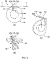
- Sub-figures (a) to (c) of Figure 5 each show a schematic view of the pump duct 31 with the rotor 26 and the blocking device 50.
Landscapes
- Engineering & Computer Science (AREA)
- Mechanical Engineering (AREA)
- General Engineering & Computer Science (AREA)
- Details And Applications Of Rotary Liquid Pumps (AREA)
- Quick-Acting Or Multi-Walled Pipe Joints (AREA)
- Details Of Reciprocating Pumps (AREA)
- Structures Of Non-Positive Displacement Pumps (AREA)
Description
- The invention relates to a pump having a rotor that is rotatable about a rotation axis and comprises a rotor hub and a rotor collar that extends from the rotor hub in the radial direction and encircles it hi an undulating manner.
- Such pumps are known as sinusoidal pumps. In a pump duct a fluid to be pumped is pumped from an inlet to an outlet by rotation of the rotor. A blocking device is provided which prevents the fluid to be pumped from being transported back from the outlet to the inlet The blocking device has a blocking element which comprises the rotor collar and blocks the pump duct in the axial direction on both sides of the rotor collar. The blocking element is mounted in a guide which allows a one-dimensional movement in the axial direction in a manner corresponding to the rotor collar encircling the rotor hub in an undulating manner.
-
EP 1 637 740 A1 shows a sinusoidal pump in which a guide and a wiper function together as blocking elements, the wiper sliding with a groove on the guide and sealing the pump channel.WO 2006/054 159 A1 discloses a variable delivery vane pump, in particular for oil, which is provided with a stator eccentrically mounted about a rotor, and wherein vanes are provided on the outside of the rotor so that they can slide in a radial direction of the rotor and stay in contact with the stator.US 1 796 535 A describes a piston blade for a compressor, wherein the blade is slidably mounted in a slot.GB 1 467 578 A - It is the object of the invention to provide a blocking device and a pump which allow improved sealing of the blocking device.
- This object is achieved by a blocking device having the features of Claim 1 and a pump having the features of Claim 7. Advantageous developments of the invention can be gathered from the dependent claims.
- A blocking device according to the invention is provided for a pump having a rotor that is rotatable about a rotation axis in a pump duct and comprises a rotor hub and a rotor collar that extends from the rotor hub in the radial direction and encircles it in an undulating manner. The blocking device comprises a plurality of blocking elements which are configured to block the pump duct in the axial direction on both sides of the rotor collar. Each of the plurality of blocking elements has a slot with a U-shaped sealing profile for abutting against the rotor collar, a sealing face for abutting against the rotor hub, and two contacting faces for abutting against a seat of the pump duct and or against a contacting face of another blocking element of the plurality of blocking elements. The plurality of blocking elements form a plurality of sealing lines on the rotor, with the result that the sealing action of the blocking element is improved. Since the blocking elements can abut against one another via the contacting faces, complex mounting of the different blocking elements is not necessary.
- Preferably, an odd number of blocking elements are provided. In this way, a middle blocking element can define a central axis or plane, relative to which the further blocking elements are arranged.
- At least two blocking elements can each be formed in a uniform manner. As a result of the use of uniform blocking elements, the design of the blocking device is simplified and assembly errors can be prevented and the production costs can be reduced. Preferably, all of the blocking elements are formed in a uniform manner. It is also possible for example for two respective blocking elements to be formed in a uniform manner and to be mounted in different orientations in the blocking device, thereby allowing for example a symmetrical configuration of the blocking device.
- According to a first preferred embodiment, the blocking elements each have parallel contacting faces. In this way, the blocking device can be configured in a compact manner. Furthermore, this allows for example employment of the blocking device according to the invention in known pump housings.
- According to an alternative embodiment, the blocking elements can each have contacting faces which are arranged at an angle and are each parallel to the radial direction of the rotor. This simplifies the geometry of the blocking elements and of the sealing faces and profiles, since blocking elements abutting against one another are each arranged in the radial direction of the rotor.
- Preferably, the blocking elements each have a sealing profile which comprises a sealing lip extending in the radial direction of the rotor. This allows a good sealing function of the respective blocking elements.
- The invention furthermore relates to a pump having a rotor that is rotatable about a rotation axis and comprises a rotor hub and a rotor collar that extends from the rotor hub in the radial direction and encircles it in an undulating manner, a pump housing having a pump duct which connects a first inlet/outlet space to a second inlet/outlet space, and an above-described blocking device.
- Further features and advantages of the invention can be gathered from the following description and from the drawings, to which reference is made. In the drawings:
- Fig. 1
- shows a pump according to the invention in an exploded perspective view having a blocking device according to the invention;
- Fig. 2
- shows the pump from
Figure 1 in an exploded side view; - Fig. 3
- shows a sectional view of the pump from
Figure 1 in the axial direction; - Fig. 4
- shows a sectional view of the pump from
Figure 3 on the section plane IV-IV; - Fig. 5
- shows schematic views of the pump duct of a pump according to the invention;
- Fig. 6
- shows a sectional view of the central housing component of the pump from
Figure 3 on the section plane VI-VI; - Fig. 7
- shows a sectional view of the central housing component according to an alternative embodiment;
- Fig. 8
- shows detail views of a blocking element and rotor according to a first embodiment of the invention;
- Fig. 9
- shows a detail view of a blocking element and rotor according to a second embodiment of the invention;
- Fig. 10
- shows a sectional view of a pump having a blocking element according to a third embodiment of the invention;
- Fig. 11
- shows detail views of a rotor of the pump from
Figure 1 ; and - Fig. 12
- shows views of the blocking device according to the invention in a pump having a guide component.
-
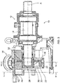
Figures 1 and 2 each show apump 10 in an exploded view. Thepump 10 comprises ashaft mounting unit 12 which supports ashaft 14. Attached to theshaft mounting unit 12 is apump housing 16 having a firstaxial housing component 18, a centralannular housing component 20 and a secondaxial housing component 22. - Provided between the first
axial housing component 18 and theshaft mounting unit 12 is asealing element 24. - The
shaft 14 projects into thepump housing 16 in a manner supported on one side. Arotor 26 comprises arotor hub 28 and arotor collar 30 that extends from therotor hub 28 in the radial direction and encircles it in an undulating manner. Therotor 26 is fastened to theshaft 14 via afastening bolt 36. The one-sided support allows a simple configuration of thepump housing 16, since it is in particular not necessary to support theshaft 14 in the secondaxial housing component 22. Some other kind of support of theshaft 14, for example a support on both sides, can also be provided. - In the following text, references to an axial direction relate to the rotation axis of the
rotor 26 and references to a radial direction relate to a corresponding radial direction centred on the rotation axis. "Axially rearward" relates to the direction pointing towards theshaft mounting unit 12 and "axially forward" relates to the direction pointing towards thepump housing 16. The firstaxial housing component 18 is thus the axially rear housing component and the secondaxial housing component 22 is thus the axially front housing component. - Provided between the
rotor 26 and the firstaxial housing component 18 is amechanical face seal 34. Instead of the mechanical face seal, some other sealing element can also be provided. - The mounting of the
shaft 14, the sealingelement 24 and themechanical face seal 34 and the fastening of therotor 26 to theshaft 14 can also be configured in some other manner. - In the embodiment shown, the
pump housing 16 is held together via fourbolts 38,washers 40 andnuts 42, wherein thebolts 38 each extend from theshaft mounting unit 12 through all threehousing components housing components pump housing 16 to theshaft mounting unit 12 can be provided or independent fastening of the secondaxial housing component 22 can be provided. This allows modular assembly and disassembly of thepump 10. Alternative ways of fastening thehousing components housing component 18 can be fastened to theshaft mounting unit 12 and thehousing components housing component 18 via grub screws in thehousing component 18. - The central
annular housing component 20 has a first inlet/outlet space 44 and a second inlet/outlet space 46, which are each formed with aconnection element 48 for connection to a pipeline. - A blocking
device 50 comprises a plurality of blockingelements 52 and is configured to block a pump duct in the axial direction on both sides of therotor collar 30. Each of the plurality of blockingelements 52 has a slot 72 with a U-shaped sealing profile 70 for abutting against therotor collar 30, a sealingface 68 for abutting against therotor hub 28, and two contactingfaces element 52 of the plurality of blockingelements 52. -
Figure 3 shows thepump 10 in a sectional view on a section plane perpendicularly through the rotation axis A of therotor 26 and theshaft 14. Thehousing components pump duct 32 together with therotor hub 28, saidpump duct 32 extending annularly around therotor hub 28. Therotor collar 30 divides thepump duct 32 into variousfluid chambers 55 by way of its undulating shape, wherein the radially outer end of the undulatingrotor collar 30 adjoins the radial outer wall, formed by theannular housing component 18, of thepump duct 32 in a sealing manner. - The blocking
device 50 is arranged in an upper sector, in the embodiment shown, of thepump duct 32. Each of the blockingelements 52 abuts in a sealing manner against the two axial side faces of therotor collar 30 and against therotor hub 28. Upon rotation of therotor 26, the blockingelements 52 can each move independently of one another in the axial direction within achamber 54 as per the undulating shape of therotating rotor collar 30. - The
chamber 54 is formed by thepump housing 16 in the embodiment shown and has aseat 60 which forms the transition between thechamber 54 and the annular pump duct 31. -
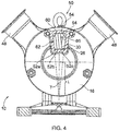
Figure 4 shows a section through thechamber 54 of thepump 10 on the section plane IV-IV inFigure 3 in the case of an anticlockwise direction of rotation of therotor 26. - A
first blocking element 52a abuts against theseat 60 of thechamber 54 with a first contactingface 62 in every axial position, and abuts against therotor collar 30 with the U-shaped sealing profile and against therotor hub 28 with the sealingface 68. Asecond blocking element 52b abuts against the second contacting face of thefirst blocking element 52a with a first contacting face and forms a second sealing line on therotor collar 30 and therotor hub 28 with the U-shaped sealing profile and the sealingface 68. Athird blocking element 52c abuts against the second contacting face of thesecond blocking element 52b with a first contacting face and forms a third sealing line on therotor collar 30 and therotor hub 28 in an analogous manner. The plurality of blockingelements 52 therefore block the annular pump duct 31 and prevent the fluid to be pumped from being transported back through the annular pump duct 31. - The second contacting
face 66 of thethird blocking element 52c is configured, in the embodiment shown, to abut against asecond seat 64 in a second operating direction, in which the rotor rotates clockwise, and thus to block the annular pump duct. This is described further below in conjunction withFigure 5 . - An
exchange duct 58 is formed within thechamber 54 and allows fluid to flow in the axial direction between the axially front fluid chamber and the axially rear fluid chamber. In this way, compression of the fluid by a change in volume during an axial movement of the blocking element and the rotor collar is avoided. - It is also possible for the blocking
elements 52 to form anexchange duct 58 which extends in the axial direction between an axially frontfluid chamber 55 and an axiallyrear fluid chamber 55 on the opposite side of therotor collar 30. This can be formed for example as a groove in one or more blocking elements or between two contacting faces, abutting against one another, of two blockingelements 52. - The
chamber 54 has four inner walls. A radially internal wall of thechamber 54 is formed in the shape of a circular arc about the rotation axis of therotor 26 axially on both sides of therotor 26 and has the same radius as or a slightly smaller radius than therotor hub 28 in order to ensure a good fit of the blockingelements 52 on therotor hub 28. - A radially external wall of the
chamber 54 has a profile that is in the shape of a circular arc about the rotation axis of therotor 26. It is also possible for the radially external wall of thechamber 54 to be formed such that it is spaced apart from the blockingelements 52, such that the fluid to be pumped on the pressure side can pass between the radially external wall of thechamber 54 and the blockingelements 52 and thus presses the blockingelements 52 against therotor hub 26. - In the circumferential direction, the
chamber 54 is formed by two flat walls that are located in the circumferential direction and each surround the flow duct in a U-shaped manner and form a first andsecond seat elements 52 in the embodiment shown. In this way, thepump 10 can be operated on both sides. - In the embodiment shown, the blocking
elements 52 are each formed with contactingfaces element 52. The two flat walls that are located in the circumferential direction are formed in this embodiment such that the blockingelement 52 can be displaced by an angle γ in the circumferential direction within thechamber 54 between the first andsecond seats - The angle γ can be in a range from 5° to 40°, wherein the angle is preferably in a range from 5° to 20°.
- To this end, the two flat walls that are located in the circumferential direction are in the radial direction with respect to a centre point which is shifted on a central axis of the pump by the distance L, wherein L = (D/2)/sin(γ/2) and D is the overall thickness of all the blocking elements 52 (in this case D=3d). In this way, the centreline of the
middle blocking element 52b is in each case oriented in the radial direction with respect to the rotation axis A when the first orsecond blocking element second seat chamber 54 by way of its contactingfaces - In order to compensate for a change in volume on account of the axial movement of the
rotor collar 30 and of the blockingelements 52, theexchange duct 58 is formed in the blockingdevice 50. This allows a flow of fluid to be pumped between the axially front fluid chamber and the axially rear fluid chamber within the blocking device. Therefore, a compact configuration of the blockingdevice 50 is allowed, since thechamber 54 of the blocking device does not have to be connected to one of the inlet/outlet spaces - In the
chamber 54, the ratio of the area of the axial flow cross section of theexchange duct 58 to the axial projection area of therotor collar 30 and of those parts of the blockingelements 52 that project beyond the rotor collar is preferably at least 0.2 and is for example in the range from 0.2 to 0.6. This allows sufficient volume compensation with a compact construction of the blockingdevice 50. - Sub-figures (a) to (c) of
Figure 5 each show a schematic view of the pump duct 31 with therotor 26 and the blockingdevice 50. - In the embodiment shown, the pump duct is formed by the
pump housing 16 itself, i.e. from the threehousing components Fig. 5 , installation space can be saved on in the region of the pump duct. Furthermore, the assembly and disassembly and also cleaning of thepump 10 are simplified. - The inlet and the outlet of the fluid to be pumped takes place via radially external inlet/
outlet spaces pump 10. - The
pump duct 32 is formed in an annular manner and extends with a constant cross section from the first radially external inlet/outlet space 44 to the second radially external inlet/outlet space 46. The blockingdevice 50 is arranged in theannular pump duct 32 between the two inlet/outlet spaces outlet spaces fluid chambers 55 formed by therotor 26 and the pump housing. When therotor 26 is rotated, the fluid chambers are moved further along theannular pump duct 32, wherein onerespective fluid chamber 56 closes and allows fluid transport in the pumping direction. On the outlet side of thepump 10, the fluid chambers move into the region of the blockingdevice 50, which blocks thepump duct 32, with the result that the fluid to be pumped flows in the radial direction out of the fluid chambers and into the outlet-side radially external inlet/outlet space. - The
pump 10 is therefore a positive displacement pump which transports a trapped fixed volume in theclosed fluid chamber 56. - The function of the blocking
device 50 is explained in the following text. The blockingdevice 50 is arranged between the first inlet/outlet space 44 and the second inlet/outlet space 46 and comprises a plurality of blockingelements 52 which block the pump duct 31 in the axial direction on both sides of therotor collar 30. In the embodiment shown inFigure 5 , three blockingelements 52 are provided. - The blocking
device 50 is configured for bidirectional operation of thepump 10. To this end, the blockingdevice 50 has afirst seat 60 for thefirst blocking element 52a on the side of the first inlet/outlet space 44, against which thefirst blocking element 52a abuts by way of a first contactingface 62 in a first operating direction for pumping from the first inlet/outlet space 44 to the second inlet/outlet space 46, seeFigure 5(a) and (b) . - The blocking device also has a
second seat 64 for thethird blocking element 52c on the side of the second inlet/outlet space 46, against which thethird blocking element 52c abuts by way of a second contactingface 66 in a second operating direction for pumping from the second inlet/outlet space 46 to the first inlet/outlet space, seeFigure 5 (c) . - The spacing between the
first seat 60 and thesecond seat 64 in the circumferential direction is greater than the spacing between the first contactingface 62 and the second contactingface 66 in the circumferential direction. - When the operating direction of the
bidirectional pump 10 is changed, all three blockingelements 52 move from thefirst seat 60 to thesecond seat 64 such that thethird blocking element 52c abuts against thesecond seat 64 by way of its second contactingface 66, thesecond blocking element 52b abuts against the first contacting face, facing the first inlet/outlet space 44, of thethird blocking element 52c via its second contacting face facing the second inlet/outlet space 46, and thefirst blocking element 52a abuts against the first contacting face, facing the first inlet/outlet space 44, of thesecond blocking element 52b via its second contacting face facing the second inlet/outlet space 46, and the respectively other contactingface pump housing 16. Furthermore, the resistance in the fluid to be pumped is reduced and thus the pressure force from the blocking elements to the rotor is reduced, with the result that the frictional forces and thus also the wear to the blockingelements 52 are reduced. - As can clearly be seen in
Figure 5(a) and (b) , the volume inchamber 54 changes when therotor 26 is rotated (from right to left in the drawing) on account of the undulating shape of the rotor collar and the blockingelements 52 moving in the axial direction. Since the blockingdevice 50 is arranged between the two inlet/outlet spaces chamber 54 of the blockingdevice 50 not to be connected to the associatedoutlet space - In order to allow this change in volume to be compensated, the
exchange duct 58 is formed between the axially front fluid chamber and the axially rear fluid chamber. A fluid flow is shown in the axial direction by the arrow inFigure 5 (b) . -
Figure 6 shows a sectional view through thecentral housing component 20 in accordance with the section plane VI-VI inFigure 3 . Thehousing component 20 is arranged such that the blockingdevice 50 with thechamber 54 is arranged in a manner rotated by 90° compared with the embodiment shown inFigure 3 , i.e. on the horizontal central axis of theannular pump duct 32. Preferably, thepump 10 is formed such that thepump housing 16 can be attached to theshaft mounting unit 12 at different angles. - The inlet/
outlet spaces annular pump duct 32, wherein a first part of the inlet/outlet spaces central housing component 20 is spaced apart from thepump duct 32 in the radial direction in the region of the inlet/outlet spaces housing component 20 narrows in the circumferential direction in the respective end region of the inlet/outlet spaces outlet spaces outlet spaces housing component 20 and forms a transition to theconnection elements 48. - The inlet/
outlet spaces housing component 20 in the embodiment shown and each extend as far as the vertical central axis of theannular pump duct 32. This allows the emptying of residues from the pump. -
Figure 7 shows a sectional view through thecentral housing component 20 as per the alternative embodiment. The embodiment differs from the embodiment shown inFigure 6 in that thehousing component 20 is not spaced apart from thepump duct 32 in the radial direction in the region of the inlet/outlet spaces - Sub-figure (a) of
Figure 8 shows an axial plan view of therotor 26 and the blockingelements 52. Sub-figure (b) shows a sectional view through the blockingelements 52 in accordance with the section plane b-b in sub-figure (a), and sub-figure (c) shows a perspective view of the components of sub-figure (a). - As can be seen in sub-
figure 8 (a) , the first and second contacting faces of theblocking elements middle blocking element 52b is formed in a symmetrical manner to its central plane in particular with regard to the sealingface 68 abutting against the rotor hub. The first andthird blocking elements middle blocking element 52b. Since theblocking elements outer blocking elements rotor collar 30 in a manner rotated by 180° with respect to one another. - As can be seen in sub-
figure 8 (b) , the U-shaped sealing profiles 70 on the slot 72 of the blockingelements 52 are each configured asconvex sealing lips 74. In order to allow optimal contact of the blockingelements 52 against therotor collar 30, the sealinglips 74 each extend in the radial direction of the rotor. Thus, the sealinglip 74 of themiddle blocking element 52b extends parallel to the lateral contacting faces, while the sealinglips 74 of theouter blocking elements - The blocking
elements 52 can furthermore also each have an inclined face which is directed at least partially in the axial direction and is configured to press theparticular blocking element 52 against therotor hub 28 in the event of an axial movement in the fluid to be pumped. For example, the surface remote from therotor hub 28 can be formed in a roof-like manner. Alternatively, an inclined face can be formed in a groove in a blockingelement 52 or in a groove between two blockingelements 52. -
Figure 9 shows a second embodiment of a blockingdevice 50 having five blockingelements 52a to 52e. In an analogous manner to the preceding embodiment, the first and second contacting faces of each blockingelement 52a to 52e extend parallel to one another. The sealinglip 74 of themiddle blocking element 52c extends parallel to the contacting faces, while the sealinglips 74 of theouter blocking elements elements elements different blocking elements 52a to 52e are formed with different thicknesses, i.e. the outer blocking elements have a greater spacing between the contacting faces than the inner blocking elements. In this way, installation space can be saved for the inner blocking elements, in the case of which the sealing lip extends parallel or at a small angle to the contacting faces, while a correspondingly greater thickness is required for theouter blocking elements lips 74 with a relatively large angle to the contacting faces. -
Figure 10 shows a third embodiment of a blockingdevice 50, in which theblocking elements 52 are configured such that the first and second contacting faces 62, 66 are arranged at an angle and each extend in the radial direction of therotor 26. In this way, all of the blockingelements 52 can be formed in an identical manner, with the result that the production costs are reduced and the assembly of the pump and the replacement of blockingelements 52 are simplified. - In
Figure 10 , the two flat walls of thechamber 54 that are located in the circumferential direction are likewise arranged in the radial direction of therotor 26. The first and second seats are thus each formed in planes which are oriented at the angle γ to one another. - The pump housing and the rotor are otherwise formed in an analogous manner to the preceding embodiments.
- Alternatively, it is also possible for the two walls that are located in the circumferential direction and the contacting faces 62, 66 of the blocking
elements 52 to each have generally cylindrical shapes, in particular curved shapes, that are coordinated with one another. Furthermore, the outer contacting faces 62, 66, in the circumferential direction, of the respectivelyouter blocking elements 52, which are configured to abut against the first andsecond seats blocking elements 52 abut against one another, for example by way of a wedge shape or arcuate shape of the blockingelement 52. - The shapes of the two walls that are located in the circumferential direction and of the contacting faces 62, 66 of the blocking
elements 52 can be selected such that the blocking elements are pressed against therotor hub 26 by the pressure difference when the pump is in operation. - Sub-figures (a) and (b) of
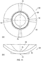
Figure 11 each show a view of therotor 26, wherein sub-figure (a) shows an axial plan view of therotor 26 and sub-figure (b) shows a radial plan view of therotor 26. - The
rotor collar 30 extends in the radial direction from therotor hub 28 and encircles therotor hub 28 in an undulating manner. In the embodiment shown, therotor collar 30 is in the two axial extreme positions at two opposite points each. Thus, the rotor collar forms two fluid chambers on each of the two axial sides of the rotor collar. - In the embodiment shown, the
rotor collar 30 extends in a flattened manner at the axialextreme positions 76, with the result that the sealing is improved at the axial end faces of thepump duct 32, which are formed by the twoaxial housing components rotor collar 30 and the axial end faces of thepump duct 32. This allows the pump to generate greater pressures with larger gap dimensions. - In the embodiment shown, the
rotor 26 is produced from an anti-seizure alloy. - Preferably, a sealing face, in the form of a circumferential groove, for a mechanical seal is provided in the
rotor hub 26. - It is also possible for other rotor shapes to be used for the pump.
- The pump housing can also be formed in some other manner. For example, the blocking
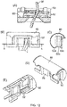
device 50 can also be provided in a known pump housing which provides only one-sided pumping operating. The plurality of blockingelements 52 can in particular also be guided in a guide which allows only a unidirectional movement in the axial direction. InFigure 12 , a blockingdevice 50 according to the invention is in a guidingcomponent 90 which allows a linear movement of the blockingelements 52 in the axial direction and forms aseat 92 for one of the blockingelements 52. The blocking elements are formed in an analogous manner to the embodiment shown inFigure 4 andFigure 8 .Fig. 12 (A) shows a sectional view through the blockingdevice 50.Fig. 12 (B) shows a view of the high-pressure side of the pump.Fig. 12 (C) shows a view in the axial direction, wherein the high-pressure side of the pump is arranged on the right and the low-pressure side of the pump is arranged on the left.Figures 12 (D) and 12 (E) each show perspective views.
Claims (7)
- Blocking device (50) for a pump (10) having a rotor (26) that is rotatable about a rotation axis (A) in a pump duct (32) and comprises a rotor hub (28) and a rotor collar (30) that extends from the rotor hub (28) in the radial direction and encircles it in an undulating manner,characterized in that the blocking device (50) comprises a plurality of blocking elements (52, 52a, 52b, 52c, 52d, 52e) which are configured to block the pump duct (32) in the axial direction on both sides of the rotor collar (30), wherein each of the plurality of blocking elements (52, 52a, 52b, 52c, 52d, 52e) has a slot with a U-shaped sealing profile for abutting against the rotor collar (30), a sealing face for abutting against the rotor hub (28), and two contacting faces for abutting against a seat (60, 66) of the pump duct (32) and/or against a contacting face (62, 66) of another blocking element (52, 52a, 52b, 52c, 52d, 52e) of the plurality of blocking elements (52, 52a, 52b, 52c, 52d, 52e), whereinthe blocking device (50) has a first seat (60) for the plurality of blocking elements (52, 52a, 52b, 52c, 52d, 52e) on the side of the first inlet/outlet space (44), against which a first one of the blocking elements (52, 52a, 52b, 52c, 52d, 52e) abuts by way of a first end contacting face (62) in a first operating direction for pumping from the first inlet/outlet space (44) to the second inlet/outlet space (46), and has a second seat (64) for the plurality of blocking elements (52, 52a, 52b, 52c, 52d, 52e) on the side of the second inlet/outlet space (46), against which a last one of the blocking elements (52, 52a, 52b, 52c, 52d, 52e) abuts by way of a second end contacting face (66) in a second operating direction for pumping from the second inlet/outlet space (46) to the first inlet/outlet space (44), andthe spacing between the first seat (60) and the second seat (64) in the circumferential direction is greater than the spacing between the respective first and second end contacting faces (62, 66) of the plurality of blocking elements (52, 52a, 52b, 52c, 52d, 52e) in the circumferential direction.
- Blocking device (50) according to Claim 1, wherein an odd number of blocking elements (52, 52a, 52b, 52c, 52d, 52e) are provided.
- Blocking device (50) according to Claim 1 or 2, wherein two blocking elements (52, 52a, 52b, 52c, 52d, 52e) are each formed in a uniform manner.
- Blocking device (50) according to one of the preceding claims, wherein the blocking elements (52, 52a, 52b, 52c, 52d, 52e) each have parallel contacting faces (62, 66).
- Blocking device (50) according to one of Claims 1 to 3, wherein the blocking elements (52, 52a, 52b, 52c, 52d, 52e) each have contacting faces (62, 66) which are arranged at an angle and are each parallel to the radial direction of the rotor (26).
- Blocking device (50) according to one of the preceding claims, wherein the blocking elements (52, 52a, 52b, 52c, 52d, 52e) each have a sealing profile which comprises a sealing lip extending in the radial direction of the rotor.
- Pump (10) having a rotor (26) that is rotatable about a rotation axis and comprises a rotor hub (28) and a rotor collar (30) that extends from the rotor hub (28) in the radial direction and encircles it in an undulating manner, a pump housing (16) having a pump duct (32) which connects a first inlet/outlet space (44) to a second inlet/outlet space (46), and a blocking device (50) according to one of the preceding claims.
Applications Claiming Priority (2)
| Application Number | Priority Date | Filing Date | Title |
|---|---|---|---|
| DE102015116770.0A DE102015116770A1 (en) | 2015-10-02 | 2015-10-02 | Pump and locking device |
| PCT/EP2016/073340 WO2017055499A1 (en) | 2015-10-02 | 2016-09-29 | Pump and blocking device |
Publications (2)
| Publication Number | Publication Date |
|---|---|
| EP3356676A1 EP3356676A1 (en) | 2018-08-08 |
| EP3356676B1 true EP3356676B1 (en) | 2021-11-10 |
Family
ID=57042886
Family Applications (1)
| Application Number | Title | Priority Date | Filing Date |
|---|---|---|---|
| EP16774669.2A Active EP3356676B1 (en) | 2015-10-02 | 2016-09-29 | Pump and blocking device |
Country Status (10)
| Country | Link |
|---|---|
| US (1) | US11125228B2 (en) |
| EP (1) | EP3356676B1 (en) |
| JP (1) | JP6721674B2 (en) |
| CN (1) | CN108026922B (en) |
| BR (1) | BR112018003620B1 (en) |
| DE (1) | DE102015116770A1 (en) |
| DK (1) | DK3356676T3 (en) |
| ES (1) | ES2905378T3 (en) |
| PT (1) | PT3356676T (en) |
| WO (1) | WO2017055499A1 (en) |
Families Citing this family (2)
| Publication number | Priority date | Publication date | Assignee | Title |
|---|---|---|---|---|
| EP3483440B1 (en) | 2017-11-08 | 2020-05-27 | Oina VV AB | Peristaltic pump |
| DE102019128678A1 (en) * | 2019-10-23 | 2021-04-29 | Qonqave Gmbh | Delivery device at least for delivering a fluid and pump with such a delivery device |
Citations (1)
| Publication number | Priority date | Publication date | Assignee | Title |
|---|---|---|---|---|
| GB1467578A (en) * | 1975-09-12 | 1977-03-16 | Kulasinghe A | Rotary positive-displacement pumps of the cam rotor type |
Family Cites Families (15)
| Publication number | Priority date | Publication date | Assignee | Title |
|---|---|---|---|---|
| US1654883A (en) * | 1926-01-11 | 1928-01-03 | Joseph F Jaworowski | Rotary pump |
| US1796535A (en) * | 1927-09-26 | 1931-03-17 | Walter G E Rolaff | Blade construction for compressors of the rotary type |
| US3156158A (en) * | 1959-08-20 | 1964-11-10 | James B Pamplin | Rotary fluid displacement apparatus |
| US3464362A (en) * | 1967-08-14 | 1969-09-02 | Milburn M Ross | Rotary power means |
| JPS6045789A (en) * | 1983-05-21 | 1985-03-12 | シネ、ポンプス、ナ−ムロ−ズ、ベンノ−トシヤツプ | Rotary liquid pump |
| US5259244A (en) * | 1991-03-19 | 1993-11-09 | Foran Jr Charles D | Sinewave flowmeter |
| US5980225A (en) * | 1996-07-05 | 1999-11-09 | Sundstrand Fluid Handling Corporation | Rotary pump having a drive shaft releasably connected to the rotor |
| AU2003301697A1 (en) * | 2002-10-31 | 2004-05-25 | Lg Electronics Inc. | Hermetic compressor having a z-plate |
| WO2005066496A1 (en) * | 2004-01-09 | 2005-07-21 | Manfred Sommer | Rotary pump provided with an axially movable blade |
| EP1637740A1 (en) | 2004-09-20 | 2006-03-22 | Sundyne Corporation | Rotary displacement pump comprising scraper and guide of the scraper |
| JP2006144592A (en) | 2004-11-17 | 2006-06-08 | Primix Copr | Rotary pump |
| ITBO20040716A1 (en) * | 2004-11-19 | 2005-02-19 | H P E High Performance Enginee | VARIABLE FLOW PUMP PUMP, IN PARTICULAR FOR OIL |
| EP2616684B1 (en) * | 2010-09-15 | 2014-07-16 | Watson-Marlow GmbH | Rotary displacement pump for pumping solids emulsions, especially liquid explosives |
| EP2565454B1 (en) | 2011-09-02 | 2016-12-14 | Watson Marlow GmbH MasoSine | Rotary displacement pump for pumping flowable materials of high viscosity |
| DE102015116768A1 (en) * | 2015-10-02 | 2017-04-20 | Watson-Marlow Gmbh | pump |
-
2015
- 2015-10-02 DE DE102015116770.0A patent/DE102015116770A1/en not_active Ceased
-
2016
- 2016-09-29 US US15/763,410 patent/US11125228B2/en not_active Expired - Fee Related
- 2016-09-29 EP EP16774669.2A patent/EP3356676B1/en active Active
- 2016-09-29 WO PCT/EP2016/073340 patent/WO2017055499A1/en not_active Ceased
- 2016-09-29 PT PT167746692T patent/PT3356676T/en unknown
- 2016-09-29 ES ES16774669T patent/ES2905378T3/en active Active
- 2016-09-29 CN CN201680056121.5A patent/CN108026922B/en active Active
- 2016-09-29 DK DK16774669.2T patent/DK3356676T3/en active
- 2016-09-29 BR BR112018003620-0A patent/BR112018003620B1/en active IP Right Grant
- 2016-09-29 JP JP2018510457A patent/JP6721674B2/en not_active Expired - Fee Related
Patent Citations (1)
| Publication number | Priority date | Publication date | Assignee | Title |
|---|---|---|---|---|
| GB1467578A (en) * | 1975-09-12 | 1977-03-16 | Kulasinghe A | Rotary positive-displacement pumps of the cam rotor type |
Also Published As
| Publication number | Publication date |
|---|---|
| EP3356676A1 (en) | 2018-08-08 |
| CN108026922A (en) | 2018-05-11 |
| JP2018529876A (en) | 2018-10-11 |
| US11125228B2 (en) | 2021-09-21 |
| BR112018003620A2 (en) | 2018-09-25 |
| DE102015116770A1 (en) | 2017-04-06 |
| BR112018003620B1 (en) | 2022-12-06 |
| CN108026922B (en) | 2020-06-05 |
| DK3356676T3 (en) | 2022-01-24 |
| PT3356676T (en) | 2021-12-09 |
| WO2017055499A1 (en) | 2017-04-06 |
| JP6721674B2 (en) | 2020-07-15 |
| ES2905378T3 (en) | 2022-04-08 |
| US20180274538A1 (en) | 2018-09-27 |
Similar Documents
| Publication | Publication Date | Title |
|---|---|---|
| EP3356649B1 (en) | Pump with axially movable vane | |
| CA2860285C (en) | Multi-stage vane pump | |
| US20130115058A1 (en) | Stator Seal Structure In Uniaxial Screw Pump | |
| US20100104462A1 (en) | Pump or motor | |
| JP5585724B2 (en) | Oil pump for vehicle | |
| EP3356648B1 (en) | Pump and blocking element | |
| EP1807625B1 (en) | Vane pump consisting a two-part stator | |
| US11125228B2 (en) | Pump including a rotor and a plurality of blocking device elements for blocking a pump duct | |
| CN103154519A (en) | Rotary displacement pump for pumping solids emulsions, especially liquid explosives | |
| EP1536138A1 (en) | Rotor machine | |
| CN106609753B (en) | Merge gerotor pump and motor | |
| US7314354B2 (en) | Rotor machine | |
| CN102782254A (en) | Volumetric Rotary Mechanism | |
| JP6553989B2 (en) | Hydraulic rotating machine |
Legal Events
| Date | Code | Title | Description |
|---|---|---|---|
| STAA | Information on the status of an ep patent application or granted ep patent |
Free format text: STATUS: THE INTERNATIONAL PUBLICATION HAS BEEN MADE |
|
| PUAI | Public reference made under article 153(3) epc to a published international application that has entered the european phase |
Free format text: ORIGINAL CODE: 0009012 |
|
| STAA | Information on the status of an ep patent application or granted ep patent |
Free format text: STATUS: REQUEST FOR EXAMINATION WAS MADE |
|
| 17P | Request for examination filed |
Effective date: 20180327 |
|
| AK | Designated contracting states |
Kind code of ref document: A1 Designated state(s): AL AT BE BG CH CY CZ DE DK EE ES FI FR GB GR HR HU IE IS IT LI LT LU LV MC MK MT NL NO PL PT RO RS SE SI SK SM TR |
|
| AX | Request for extension of the european patent |
Extension state: BA ME |
|
| DAV | Request for validation of the european patent (deleted) | ||
| DAX | Request for extension of the european patent (deleted) | ||
| STAA | Information on the status of an ep patent application or granted ep patent |
Free format text: STATUS: EXAMINATION IS IN PROGRESS |
|
| 17Q | First examination report despatched |
Effective date: 20201111 |
|
| GRAP | Despatch of communication of intention to grant a patent |
Free format text: ORIGINAL CODE: EPIDOSNIGR1 |
|
| STAA | Information on the status of an ep patent application or granted ep patent |
Free format text: STATUS: GRANT OF PATENT IS INTENDED |
|
| INTG | Intention to grant announced |
Effective date: 20210705 |
|
| GRAS | Grant fee paid |
Free format text: ORIGINAL CODE: EPIDOSNIGR3 |
|
| GRAA | (expected) grant |
Free format text: ORIGINAL CODE: 0009210 |
|
| STAA | Information on the status of an ep patent application or granted ep patent |
Free format text: STATUS: THE PATENT HAS BEEN GRANTED |
|
| AK | Designated contracting states |
Kind code of ref document: B1 Designated state(s): AL AT BE BG CH CY CZ DE DK EE ES FI FR GB GR HR HU IE IS IT LI LT LU LV MC MK MT NL NO PL PT RO RS SE SI SK SM TR |
|
| REG | Reference to a national code |
Ref country code: GB Ref legal event code: FG4D |
|
| RIN1 | Information on inventor provided before grant (corrected) |
Inventor name: MAYER, ERIC Inventor name: STAEDELE, ACHIM |
|
| REG | Reference to a national code |
Ref country code: AT Ref legal event code: REF Ref document number: 1446332 Country of ref document: AT Kind code of ref document: T Effective date: 20211115 Ref country code: CH Ref legal event code: EP |
|
| REG | Reference to a national code |
Ref country code: DE Ref legal event code: R096 Ref document number: 602016066059 Country of ref document: DE |
|
| REG | Reference to a national code |
Ref country code: IE Ref legal event code: FG4D |
|
| REG | Reference to a national code |
Ref country code: PT Ref legal event code: SC4A Ref document number: 3356676 Country of ref document: PT Date of ref document: 20211209 Kind code of ref document: T Free format text: AVAILABILITY OF NATIONAL TRANSLATION Effective date: 20211202 |
|
| REG | Reference to a national code |
Ref country code: SE Ref legal event code: TRGR |
|
| REG | Reference to a national code |
Ref country code: NL Ref legal event code: FP |
|
| REG | Reference to a national code |
Ref country code: FI Ref legal event code: FGE Ref country code: DK Ref legal event code: T3 Effective date: 20220118 |
|
| REG | Reference to a national code |
Ref country code: LT Ref legal event code: MG9D |
|
| REG | Reference to a national code |
Ref country code: NO Ref legal event code: T2 Effective date: 20211110 |
|
| REG | Reference to a national code |
Ref country code: ES Ref legal event code: FG2A Ref document number: 2905378 Country of ref document: ES Kind code of ref document: T3 Effective date: 20220408 |
|
| PG25 | Lapsed in a contracting state [announced via postgrant information from national office to epo] |
Ref country code: RS Free format text: LAPSE BECAUSE OF FAILURE TO SUBMIT A TRANSLATION OF THE DESCRIPTION OR TO PAY THE FEE WITHIN THE PRESCRIBED TIME-LIMIT Effective date: 20211110 Ref country code: LT Free format text: LAPSE BECAUSE OF FAILURE TO SUBMIT A TRANSLATION OF THE DESCRIPTION OR TO PAY THE FEE WITHIN THE PRESCRIBED TIME-LIMIT Effective date: 20211110 Ref country code: BG Free format text: LAPSE BECAUSE OF FAILURE TO SUBMIT A TRANSLATION OF THE DESCRIPTION OR TO PAY THE FEE WITHIN THE PRESCRIBED TIME-LIMIT Effective date: 20220210 |
|
| REG | Reference to a national code |
Ref country code: AT Ref legal event code: UEP Ref document number: 1446332 Country of ref document: AT Kind code of ref document: T Effective date: 20211110 |
|
| PG25 | Lapsed in a contracting state [announced via postgrant information from national office to epo] |
Ref country code: IS Free format text: LAPSE BECAUSE OF FAILURE TO SUBMIT A TRANSLATION OF THE DESCRIPTION OR TO PAY THE FEE WITHIN THE PRESCRIBED TIME-LIMIT Effective date: 20220310 Ref country code: PL Free format text: LAPSE BECAUSE OF FAILURE TO SUBMIT A TRANSLATION OF THE DESCRIPTION OR TO PAY THE FEE WITHIN THE PRESCRIBED TIME-LIMIT Effective date: 20211110 Ref country code: LV Free format text: LAPSE BECAUSE OF FAILURE TO SUBMIT A TRANSLATION OF THE DESCRIPTION OR TO PAY THE FEE WITHIN THE PRESCRIBED TIME-LIMIT Effective date: 20211110 Ref country code: HR Free format text: LAPSE BECAUSE OF FAILURE TO SUBMIT A TRANSLATION OF THE DESCRIPTION OR TO PAY THE FEE WITHIN THE PRESCRIBED TIME-LIMIT Effective date: 20211110 Ref country code: GR Free format text: LAPSE BECAUSE OF FAILURE TO SUBMIT A TRANSLATION OF THE DESCRIPTION OR TO PAY THE FEE WITHIN THE PRESCRIBED TIME-LIMIT Effective date: 20220211 |
|
| PG25 | Lapsed in a contracting state [announced via postgrant information from national office to epo] |
Ref country code: SM Free format text: LAPSE BECAUSE OF FAILURE TO SUBMIT A TRANSLATION OF THE DESCRIPTION OR TO PAY THE FEE WITHIN THE PRESCRIBED TIME-LIMIT Effective date: 20211110 Ref country code: SK Free format text: LAPSE BECAUSE OF FAILURE TO SUBMIT A TRANSLATION OF THE DESCRIPTION OR TO PAY THE FEE WITHIN THE PRESCRIBED TIME-LIMIT Effective date: 20211110 Ref country code: RO Free format text: LAPSE BECAUSE OF FAILURE TO SUBMIT A TRANSLATION OF THE DESCRIPTION OR TO PAY THE FEE WITHIN THE PRESCRIBED TIME-LIMIT Effective date: 20211110 Ref country code: EE Free format text: LAPSE BECAUSE OF FAILURE TO SUBMIT A TRANSLATION OF THE DESCRIPTION OR TO PAY THE FEE WITHIN THE PRESCRIBED TIME-LIMIT Effective date: 20211110 Ref country code: CZ Free format text: LAPSE BECAUSE OF FAILURE TO SUBMIT A TRANSLATION OF THE DESCRIPTION OR TO PAY THE FEE WITHIN THE PRESCRIBED TIME-LIMIT Effective date: 20211110 |
|
| REG | Reference to a national code |
Ref country code: DE Ref legal event code: R097 Ref document number: 602016066059 Country of ref document: DE |
|
| PLBE | No opposition filed within time limit |
Free format text: ORIGINAL CODE: 0009261 |
|
| STAA | Information on the status of an ep patent application or granted ep patent |
Free format text: STATUS: NO OPPOSITION FILED WITHIN TIME LIMIT |
|
| 26N | No opposition filed |
Effective date: 20220811 |
|
| PG25 | Lapsed in a contracting state [announced via postgrant information from national office to epo] |
Ref country code: AL Free format text: LAPSE BECAUSE OF FAILURE TO SUBMIT A TRANSLATION OF THE DESCRIPTION OR TO PAY THE FEE WITHIN THE PRESCRIBED TIME-LIMIT Effective date: 20211110 |
|
| PG25 | Lapsed in a contracting state [announced via postgrant information from national office to epo] |
Ref country code: SI Free format text: LAPSE BECAUSE OF FAILURE TO SUBMIT A TRANSLATION OF THE DESCRIPTION OR TO PAY THE FEE WITHIN THE PRESCRIBED TIME-LIMIT Effective date: 20211110 |
|
| PG25 | Lapsed in a contracting state [announced via postgrant information from national office to epo] |
Ref country code: MC Free format text: LAPSE BECAUSE OF FAILURE TO SUBMIT A TRANSLATION OF THE DESCRIPTION OR TO PAY THE FEE WITHIN THE PRESCRIBED TIME-LIMIT Effective date: 20211110 |
|
| P01 | Opt-out of the competence of the unified patent court (upc) registered |
Effective date: 20230524 |
|
| PG25 | Lapsed in a contracting state [announced via postgrant information from national office to epo] |
Ref country code: LU Free format text: LAPSE BECAUSE OF NON-PAYMENT OF DUE FEES Effective date: 20220929 |
|
| PG25 | Lapsed in a contracting state [announced via postgrant information from national office to epo] |
Ref country code: HU Free format text: LAPSE BECAUSE OF FAILURE TO SUBMIT A TRANSLATION OF THE DESCRIPTION OR TO PAY THE FEE WITHIN THE PRESCRIBED TIME-LIMIT; INVALID AB INITIO Effective date: 20160929 |
|
| PG25 | Lapsed in a contracting state [announced via postgrant information from national office to epo] |
Ref country code: CY Free format text: LAPSE BECAUSE OF FAILURE TO SUBMIT A TRANSLATION OF THE DESCRIPTION OR TO PAY THE FEE WITHIN THE PRESCRIBED TIME-LIMIT Effective date: 20211110 |
|
| PG25 | Lapsed in a contracting state [announced via postgrant information from national office to epo] |
Ref country code: MK Free format text: LAPSE BECAUSE OF FAILURE TO SUBMIT A TRANSLATION OF THE DESCRIPTION OR TO PAY THE FEE WITHIN THE PRESCRIBED TIME-LIMIT Effective date: 20211110 |
|
| PG25 | Lapsed in a contracting state [announced via postgrant information from national office to epo] |
Ref country code: MT Free format text: LAPSE BECAUSE OF FAILURE TO SUBMIT A TRANSLATION OF THE DESCRIPTION OR TO PAY THE FEE WITHIN THE PRESCRIBED TIME-LIMIT Effective date: 20211110 |
|
| PGFP | Annual fee paid to national office [announced via postgrant information from national office to epo] |
Ref country code: FI Payment date: 20240904 Year of fee payment: 9 Ref country code: IE Payment date: 20240905 Year of fee payment: 9 Ref country code: DE Payment date: 20240924 Year of fee payment: 9 |
|
| PGFP | Annual fee paid to national office [announced via postgrant information from national office to epo] |
Ref country code: DK Payment date: 20240923 Year of fee payment: 9 |
|
| PGFP | Annual fee paid to national office [announced via postgrant information from national office to epo] |
Ref country code: PT Payment date: 20240906 Year of fee payment: 9 Ref country code: GB Payment date: 20240925 Year of fee payment: 9 |
|
| PGFP | Annual fee paid to national office [announced via postgrant information from national office to epo] |
Ref country code: BE Payment date: 20240911 Year of fee payment: 9 |
|
| PGFP | Annual fee paid to national office [announced via postgrant information from national office to epo] |
Ref country code: FR Payment date: 20240909 Year of fee payment: 9 |
|
| PGFP | Annual fee paid to national office [announced via postgrant information from national office to epo] |
Ref country code: NL Payment date: 20240924 Year of fee payment: 9 |
|
| PGFP | Annual fee paid to national office [announced via postgrant information from national office to epo] |
Ref country code: AT Payment date: 20240904 Year of fee payment: 9 |
|
| PGFP | Annual fee paid to national office [announced via postgrant information from national office to epo] |
Ref country code: NO Payment date: 20240905 Year of fee payment: 9 Ref country code: IT Payment date: 20240916 Year of fee payment: 9 Ref country code: SE Payment date: 20240924 Year of fee payment: 9 |
|
| PGFP | Annual fee paid to national office [announced via postgrant information from national office to epo] |
Ref country code: ES Payment date: 20241010 Year of fee payment: 9 |
|
| PGFP | Annual fee paid to national office [announced via postgrant information from national office to epo] |
Ref country code: CH Payment date: 20241001 Year of fee payment: 9 |
|
| PG25 | Lapsed in a contracting state [announced via postgrant information from national office to epo] |
Ref country code: TR Free format text: LAPSE BECAUSE OF FAILURE TO SUBMIT A TRANSLATION OF THE DESCRIPTION OR TO PAY THE FEE WITHIN THE PRESCRIBED TIME-LIMIT Effective date: 20211110 |
|
| PG25 | Lapsed in a contracting state [announced via postgrant information from national office to epo] |
Ref country code: FI Free format text: LAPSE BECAUSE OF NON-PAYMENT OF DUE FEES Effective date: 20250929 |
|
| REG | Reference to a national code |
Ref country code: DK Ref legal event code: EBP Effective date: 20250930 |
|
| PG25 | Lapsed in a contracting state [announced via postgrant information from national office to epo] |
Ref country code: PT Free format text: LAPSE BECAUSE OF NON-PAYMENT OF DUE FEES Effective date: 20260330 |
|
| REG | Reference to a national code |
Ref country code: CH Ref legal event code: H13 Free format text: ST27 STATUS EVENT CODE: U-0-0-H10-H13 (AS PROVIDED BY THE NATIONAL OFFICE) Effective date: 20260504 |
|
| REG | Reference to a national code |
Ref country code: NL Ref legal event code: MM Effective date: 20251001 |