EP3356267B1 - Élément de sollicitation d'assistance de coupe de fardage - Google Patents
Élément de sollicitation d'assistance de coupe de fardage Download PDFInfo
- Publication number
- EP3356267B1 EP3356267B1 EP16852775.2A EP16852775A EP3356267B1 EP 3356267 B1 EP3356267 B1 EP 3356267B1 EP 16852775 A EP16852775 A EP 16852775A EP 3356267 B1 EP3356267 B1 EP 3356267B1
- Authority
- EP
- European Patent Office
- Prior art keywords
- cutting
- dunnage material
- biasing member
- dunnage
- cutting member
- Prior art date
- Legal status (The legal status is an assumption and is not a legal conclusion. Google has not performed a legal analysis and makes no representation as to the accuracy of the status listed.)
- Active
Links
- 239000000463 material Substances 0.000 claims description 272
- 238000005520 cutting process Methods 0.000 claims description 194
- 238000006243 chemical reaction Methods 0.000 claims description 63
- 230000007246 mechanism Effects 0.000 claims description 50
- 230000002441 reversible effect Effects 0.000 claims description 29
- 230000004044 response Effects 0.000 claims description 11
- 238000012545 processing Methods 0.000 claims description 9
- 238000005452 bending Methods 0.000 claims description 2
- 238000000034 method Methods 0.000 description 13
- 230000033001 locomotion Effects 0.000 description 8
- 230000003993 interaction Effects 0.000 description 7
- 230000008859 change Effects 0.000 description 5
- 230000005540 biological transmission Effects 0.000 description 4
- 239000000853 adhesive Substances 0.000 description 2
- 230000001070 adhesive effect Effects 0.000 description 2
- 239000013590 bulk material Substances 0.000 description 2
- 239000005022 packaging material Substances 0.000 description 2
- 238000004806 packaging method and process Methods 0.000 description 2
- 230000036961 partial effect Effects 0.000 description 2
- 238000003825 pressing Methods 0.000 description 2
- 230000008569 process Effects 0.000 description 2
- 230000001681 protective effect Effects 0.000 description 2
- 238000003860 storage Methods 0.000 description 2
- 239000011800 void material Substances 0.000 description 2
- 229920002472 Starch Polymers 0.000 description 1
- 230000009471 action Effects 0.000 description 1
- 230000008901 benefit Effects 0.000 description 1
- 229920002678 cellulose Polymers 0.000 description 1
- 239000001913 cellulose Substances 0.000 description 1
- 238000004891 communication Methods 0.000 description 1
- 239000000835 fiber Substances 0.000 description 1
- 239000002657 fibrous material Substances 0.000 description 1
- 230000006870 function Effects 0.000 description 1
- 230000000670 limiting effect Effects 0.000 description 1
- 238000005259 measurement Methods 0.000 description 1
- 239000000203 mixture Substances 0.000 description 1
- 239000004033 plastic Substances 0.000 description 1
- 230000002829 reductive effect Effects 0.000 description 1
- -1 ropes or thread Substances 0.000 description 1
- 238000000926 separation method Methods 0.000 description 1
- 238000004904 shortening Methods 0.000 description 1
- 238000009751 slip forming Methods 0.000 description 1
- 239000007779 soft material Substances 0.000 description 1
- 239000008107 starch Substances 0.000 description 1
- 235000019698 starch Nutrition 0.000 description 1
- 229920002994 synthetic fiber Polymers 0.000 description 1
- 239000012815 thermoplastic material Substances 0.000 description 1
Images


Classifications
-
- B—PERFORMING OPERATIONS; TRANSPORTING
- B31—MAKING ARTICLES OF PAPER, CARDBOARD OR MATERIAL WORKED IN A MANNER ANALOGOUS TO PAPER; WORKING PAPER, CARDBOARD OR MATERIAL WORKED IN A MANNER ANALOGOUS TO PAPER
- B31D—MAKING ARTICLES OF PAPER, CARDBOARD OR MATERIAL WORKED IN A MANNER ANALOGOUS TO PAPER, NOT PROVIDED FOR IN SUBCLASSES B31B OR B31C
- B31D5/00—Multiple-step processes for making three-dimensional articles ; Making three-dimensional articles
- B31D5/0039—Multiple-step processes for making three-dimensional articles ; Making three-dimensional articles for making dunnage or cushion pads
- B31D5/0043—Multiple-step processes for making three-dimensional articles ; Making three-dimensional articles for making dunnage or cushion pads including crumpling flat material
-
- B—PERFORMING OPERATIONS; TRANSPORTING
- B31—MAKING ARTICLES OF PAPER, CARDBOARD OR MATERIAL WORKED IN A MANNER ANALOGOUS TO PAPER; WORKING PAPER, CARDBOARD OR MATERIAL WORKED IN A MANNER ANALOGOUS TO PAPER
- B31D—MAKING ARTICLES OF PAPER, CARDBOARD OR MATERIAL WORKED IN A MANNER ANALOGOUS TO PAPER, NOT PROVIDED FOR IN SUBCLASSES B31B OR B31C
- B31D5/00—Multiple-step processes for making three-dimensional articles ; Making three-dimensional articles
- B31D5/0039—Multiple-step processes for making three-dimensional articles ; Making three-dimensional articles for making dunnage or cushion pads
-
- B—PERFORMING OPERATIONS; TRANSPORTING
- B65—CONVEYING; PACKING; STORING; HANDLING THIN OR FILAMENTARY MATERIAL
- B65H—HANDLING THIN OR FILAMENTARY MATERIAL, e.g. SHEETS, WEBS, CABLES
- B65H35/00—Delivering articles from cutting or line-perforating machines; Article or web delivery apparatus incorporating cutting or line-perforating devices, e.g. adhesive tape dispensers
- B65H35/0006—Article or web delivery apparatus incorporating cutting or line-perforating devices
- B65H35/0073—Details
- B65H35/008—Arrangements or adaptations of cutting devices
-
- B—PERFORMING OPERATIONS; TRANSPORTING
- B26—HAND CUTTING TOOLS; CUTTING; SEVERING
- B26D—CUTTING; DETAILS COMMON TO MACHINES FOR PERFORATING, PUNCHING, CUTTING-OUT, STAMPING-OUT OR SEVERING
- B26D1/00—Cutting through work characterised by the nature or movement of the cutting member or particular materials not otherwise provided for; Apparatus or machines therefor; Cutting members therefor
- B26D1/01—Cutting through work characterised by the nature or movement of the cutting member or particular materials not otherwise provided for; Apparatus or machines therefor; Cutting members therefor involving a cutting member which does not travel with the work
- B26D1/02—Cutting through work characterised by the nature or movement of the cutting member or particular materials not otherwise provided for; Apparatus or machines therefor; Cutting members therefor involving a cutting member which does not travel with the work having a stationary cutting member
- B26D1/025—Cutting through work characterised by the nature or movement of the cutting member or particular materials not otherwise provided for; Apparatus or machines therefor; Cutting members therefor involving a cutting member which does not travel with the work having a stationary cutting member for thin material, e.g. for sheets, strips or the like
-
- B—PERFORMING OPERATIONS; TRANSPORTING
- B26—HAND CUTTING TOOLS; CUTTING; SEVERING
- B26D—CUTTING; DETAILS COMMON TO MACHINES FOR PERFORATING, PUNCHING, CUTTING-OUT, STAMPING-OUT OR SEVERING
- B26D1/00—Cutting through work characterised by the nature or movement of the cutting member or particular materials not otherwise provided for; Apparatus or machines therefor; Cutting members therefor
- B26D1/0006—Cutting members therefor
- B26D2001/006—Cutting members therefor the cutting blade having a special shape, e.g. a special outline, serrations
-
- B—PERFORMING OPERATIONS; TRANSPORTING
- B26—HAND CUTTING TOOLS; CUTTING; SEVERING
- B26D—CUTTING; DETAILS COMMON TO MACHINES FOR PERFORATING, PUNCHING, CUTTING-OUT, STAMPING-OUT OR SEVERING
- B26D7/00—Details of apparatus for cutting, cutting-out, stamping-out, punching, perforating, or severing by means other than cutting
- B26D7/08—Means for treating work or cutting member to facilitate cutting
- B26D2007/082—Guiding or pushing a web into a favorable position by deflector means
-
- B—PERFORMING OPERATIONS; TRANSPORTING
- B26—HAND CUTTING TOOLS; CUTTING; SEVERING
- B26F—PERFORATING; PUNCHING; CUTTING-OUT; STAMPING-OUT; SEVERING BY MEANS OTHER THAN CUTTING
- B26F3/00—Severing by means other than cutting; Apparatus therefor
- B26F3/02—Tearing
-
- B—PERFORMING OPERATIONS; TRANSPORTING
- B31—MAKING ARTICLES OF PAPER, CARDBOARD OR MATERIAL WORKED IN A MANNER ANALOGOUS TO PAPER; WORKING PAPER, CARDBOARD OR MATERIAL WORKED IN A MANNER ANALOGOUS TO PAPER
- B31D—MAKING ARTICLES OF PAPER, CARDBOARD OR MATERIAL WORKED IN A MANNER ANALOGOUS TO PAPER, NOT PROVIDED FOR IN SUBCLASSES B31B OR B31C
- B31D2205/00—Multiple-step processes for making three-dimensional articles
- B31D2205/0005—Multiple-step processes for making three-dimensional articles for making dunnage or cushion pads
- B31D2205/0011—Multiple-step processes for making three-dimensional articles for making dunnage or cushion pads including particular additional operations
- B31D2205/0017—Providing stock material in a particular form
- B31D2205/0023—Providing stock material in a particular form as web from a roll
-
- B—PERFORMING OPERATIONS; TRANSPORTING
- B31—MAKING ARTICLES OF PAPER, CARDBOARD OR MATERIAL WORKED IN A MANNER ANALOGOUS TO PAPER; WORKING PAPER, CARDBOARD OR MATERIAL WORKED IN A MANNER ANALOGOUS TO PAPER
- B31D—MAKING ARTICLES OF PAPER, CARDBOARD OR MATERIAL WORKED IN A MANNER ANALOGOUS TO PAPER, NOT PROVIDED FOR IN SUBCLASSES B31B OR B31C
- B31D2205/00—Multiple-step processes for making three-dimensional articles
- B31D2205/0005—Multiple-step processes for making three-dimensional articles for making dunnage or cushion pads
- B31D2205/0011—Multiple-step processes for making three-dimensional articles for making dunnage or cushion pads including particular additional operations
- B31D2205/0017—Providing stock material in a particular form
- B31D2205/0035—Providing stock material in a particular form as fan folded web
-
- B—PERFORMING OPERATIONS; TRANSPORTING
- B31—MAKING ARTICLES OF PAPER, CARDBOARD OR MATERIAL WORKED IN A MANNER ANALOGOUS TO PAPER; WORKING PAPER, CARDBOARD OR MATERIAL WORKED IN A MANNER ANALOGOUS TO PAPER
- B31D—MAKING ARTICLES OF PAPER, CARDBOARD OR MATERIAL WORKED IN A MANNER ANALOGOUS TO PAPER, NOT PROVIDED FOR IN SUBCLASSES B31B OR B31C
- B31D2205/00—Multiple-step processes for making three-dimensional articles
- B31D2205/0005—Multiple-step processes for making three-dimensional articles for making dunnage or cushion pads
- B31D2205/0011—Multiple-step processes for making three-dimensional articles for making dunnage or cushion pads including particular additional operations
- B31D2205/0058—Cutting; Individualising the final products
-
- B—PERFORMING OPERATIONS; TRANSPORTING
- B31—MAKING ARTICLES OF PAPER, CARDBOARD OR MATERIAL WORKED IN A MANNER ANALOGOUS TO PAPER; WORKING PAPER, CARDBOARD OR MATERIAL WORKED IN A MANNER ANALOGOUS TO PAPER
- B31D—MAKING ARTICLES OF PAPER, CARDBOARD OR MATERIAL WORKED IN A MANNER ANALOGOUS TO PAPER, NOT PROVIDED FOR IN SUBCLASSES B31B OR B31C
- B31D2205/00—Multiple-step processes for making three-dimensional articles
- B31D2205/0005—Multiple-step processes for making three-dimensional articles for making dunnage or cushion pads
- B31D2205/0076—Multiple-step processes for making three-dimensional articles for making dunnage or cushion pads involving particular machinery details
- B31D2205/0082—General layout of the machinery or relative arrangement of its subunits
-
- B—PERFORMING OPERATIONS; TRANSPORTING
- B31—MAKING ARTICLES OF PAPER, CARDBOARD OR MATERIAL WORKED IN A MANNER ANALOGOUS TO PAPER; WORKING PAPER, CARDBOARD OR MATERIAL WORKED IN A MANNER ANALOGOUS TO PAPER
- B31D—MAKING ARTICLES OF PAPER, CARDBOARD OR MATERIAL WORKED IN A MANNER ANALOGOUS TO PAPER, NOT PROVIDED FOR IN SUBCLASSES B31B OR B31C
- B31D5/00—Multiple-step processes for making three-dimensional articles ; Making three-dimensional articles
- B31D5/0039—Multiple-step processes for making three-dimensional articles ; Making three-dimensional articles for making dunnage or cushion pads
- B31D5/0043—Multiple-step processes for making three-dimensional articles ; Making three-dimensional articles for making dunnage or cushion pads including crumpling flat material
- B31D5/0052—Multiple-step processes for making three-dimensional articles ; Making three-dimensional articles for making dunnage or cushion pads including crumpling flat material involving rollers
-
- B—PERFORMING OPERATIONS; TRANSPORTING
- B65—CONVEYING; PACKING; STORING; HANDLING THIN OR FILAMENTARY MATERIAL
- B65H—HANDLING THIN OR FILAMENTARY MATERIAL, e.g. SHEETS, WEBS, CABLES
- B65H2801/00—Application field
- B65H2801/63—Dunnage conversion
Definitions
- An apparatus for processing dunnage material is disclosed herein. More particularly, an apparatus for assisting a user in cutting the dunnage material at a desired point is disclosed.
- paper sheet is crumpled to produce the dunnage.
- this type of dunnage is created by running a generally continuous strip of paper into a dunnage conversion machine that converts a compact supply of stock material, such as a roll of paper or a fanfold stack of paper, into a lower density dunnage material.
- the supply of stock material such as in the case of fanfold paper, is pulled into the conversion machine from a stack that is either continuously formed or formed with discrete section connected together.
- the continuous strip of crumpled sheet material may be cut into desired lengths to effectively fill void space within a container holding a product.
- the dunnage material may be produced on an as-needed basis for a packer.
- Examples of cushioning product machines that feed a paper sheet from an innermost location of a roll are described in U.S. Pat. Pub. No. 2013/0092716 , U.S. Pat. Pub. No. 2008/0076653 , and U.S. Pat. Pub. No. 2008/0261794 .
- Another example of a cushioning product machine is described in U.S. Patent Publication No. 2009/0026306 .
- US 2,195,603 A and US 2013/092716 A disclose a conversion apparatus for processing a dunnage material along a path with a cutting member having an edge configured for cutting or tearing the dunnage material, wherein US 2013/092716 A further comprises a driving mechanism that drives the dunnage material in a reverse direction to facilitate to sever a dunnage material.
- the paper feed is controlled by a timer that interacts with a stop arm.
- a conversion apparatus in accordance with various embodiments, includes a cutting member having an edge configured for cutting the dunnage material.
- the conversion apparatus also includes a biasing member located adjacent to the cutting member and having a cutting position in which the dunnage material passes between the biasing member and the cutting member with the biasing member bending the dunnage material along a path around the end of the cutting member so that in response to the dunnage material being retracted back into the conversion apparatus the cutting member begins to sever the dunnage material.
- the conversion apparatus comprises a driving mechanism as described in paragraph [0010].
- the path includes an elbow defined where the dunnage material is bent around the cutting member, wherein in a dispensing direction, the elbow biases the dunnage away from the cutting member but in the reverse direction the elbow biases the dunnage toward the cutting member.
- the biasing member is movable between the cutting position and a dispensing position.
- the cutting member includes teeth having adjacent points with a trough there between.
- the biasing member can include a plurality of fingers. The plurality of figures can be positioned relative to one another such that, in response to moving toward the cutting member and into the cutting position, each finger fits into the trough between the adjacent points of the cutting member teeth.
- the conversion apparatus also includes a drum that is rotated by the drive mechanism and contacts the dunnage material to advance the dunnage material in the first direction and retract the dunnage material in the second direction within the apparatus.
- the drum drives a biasing linkage that actuates the biasing member.
- the biasing linkage can include an actuator wheel that is positioned adjacent the drum such that the dunnage material is guided between the actuator wheel and the drum.
- the actuator wheel can be in mechanical connection with the biasing member such that rotation of the actuator wheel drives the biasing linkage.
- the biasing linkage can include an actuator arm associated with the actuator wheel. The actuator arm rotates with actuation of the biasing member.
- the angular rotation of the actuator arm rotates less than a full rotation while the actuator wheel is operable to continually rotate.
- the actuator arm is connected to the biasing member through a link member having a pivot connection at the actuator arm and a pivot connection at the biasing member causing angular rotation of the actuator arm to correspond to angular rotation of the biasing member.
- the biasing linkage can include the biasing linkage includes opposing actuator arms, opposing links, and opposing biasing members that each operate on opposing sides of the path of the dunnage material.
- the actuator arm includes a slot with the ends of the slot defining a first position and a second position forming limits to the angular rotation of the actuator arm.
- the actuator arm can be connected to an actuator wheel through a clutch mechanism.
- the clutch mechanism can include a belt attached at each end to the actuator arm. The belt can wrap more than 90 degrees around the actuator wheel.
- the clutch mechanism allows the actuator wheel to rotate relative to the actuator arm once the arm extends to the first position. This allows the actuator wheel to rotate with the actuator arm between the first position and the second positon.
- the clutch mechanism then allows the actuator wheel to rotate relative to the actuator arm once the arm extends to the second position.
- the actuator wheel and the drum are connected such that they rotate together.
- the drum can be rotated by the drive mechanism, which in turn advances the dunnage material and rotates the actuator wheel.
- the conversion apparatus can also includes a converting station that is configured to form dunnage out of the dunnage material prior to feeding the dunnage material through the apparatus.
- the biasing member deflects the material path when the biasing member is in the cutting position such that the material path forms a bend of between 15° and 90°.
- the biasing member deflects the material path when the biasing member is in the cutting position such that the material path forms a bend of about 45°.
- the biasing member directly forces the dunnage material against the cutting member where the dunnage material contacts the cutting member when the biasing member is in the cutting position.
- a conversion apparatus for processing a dunnage material along a path include a cutting member with an edge suitable for cutting or tearing the dunnage material.
- the conversion apparatus also include a biasing member positioned adjacent to the cutting member such that the dunnage material passes between the biasing member and the cutting member.
- the biasing member is movable between the dispensing position and the cutting position relative to the cutting mechanism such that the biasing member is operable to bend the dunnage material around the edge of the cutting member in the cutting position.
- a cutting member include an edge suitable for cutting or tearing the dunnage material.
- a biasing member be positioned adjacent to the cutting member such that the dunnage material passes between the biasing member and the cutting member.
- the biasing member is movable relative to the cutting mechanism between the dispensing position configured to allow the dunnage material to exit from the apparatus and the cutting position that bends the dunnage material around the edge of the cutting member in the cutting position to cause the cutting member to sever the dunnage material.
- the conversion apparatus also include a driving mechanism that drives the dunnage material in the dispensing direction causing the dunnage material to be dispensed and in a reverse direction opposite the dispensing direction along the path.
- a driving mechanism that drives the dunnage material in the dispensing direction causing the dunnage material to be dispensed and in a reverse direction opposite the dispensing direction along the path.
- the biasing member In response to the driving mechanism driving the dunnage material in the reverse direction, the biasing member is moved into the cutting position and biases the dunnage material around the edge and in response to the driving mechanism driving the stock in the dispensing direction the biasing member is moved into the dispensing position away from the cutting member such that the dunnage material is not biased around the edge of the cutting member.
- the conversion apparatus can also include a drum that is rotated by the drive mechanism and contacts the dunnage material to advance the dunnage material in the first direction and retract the dunnage material in the second direction within the apparatus, wherein the drum drives a biasing linkage that actuates the biasing member by rotating an actuator arm that is connected through a friction connection with an actuator wheel that is driven by at least one of the drum or a pinch wheel opposing the drum.
- An apparatus for converting a stock material into dunnage is disclosed. More particularly, the conversion apparatus including a mechanism for cutting or assisting the cutting of the dunnage material at desired lengths is disclosed.
- the present disclosure is generally applicable to systems and apparatus where supply material, such as a stock material, is processed.
- the stock material may be stored in a roll (whether drawn from inside or outside the roll), a wind, a fan-folded source, or any other form.
- the stock material may be continuous or perforated.
- the conversion apparatus is operable to drive the stock material in a first direction, which is the dispensing direction.
- the conversion apparatus is fed the stock material from the repository through a drum in the dispensing direction.
- the stock material can be any type of protective packaging material including other dunnage and void fill materials, inflatable packaging pillows, etc. Some embodiments use supplies of other paper or fiber-based materials in sheet form, and some embodiments use supplies of wound fiber material such as ropes or thread, and thermoplastic materials such as a web of plastic material usable to form pillow packaging material.
- the conversion apparatus is used with a cutting mechanism operable to sever the dunnage material.
- the cutting mechanism is used with no or limited user interaction.
- the cutting mechanism punctures, cuts, or severs the dunnage material without the user touching the dunnage material or with only minor contact of the dunnage material by the user.
- a biasing member is used to bias the dunnage material against or around a cutting member to improve the ability of the system to sever the dunnage material.
- the biased position of the dunnage material is used in connection with or separately from other cutting features such as reversing the direction of travel of the dunnage material.
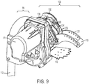
- a dunnage conversion system 10 for processing a stock material 21. Covers, guards, external elements, etc., may be removed from the various views shown to provide clarity to the structure discussed herein.
- Fig. 1 illustrates drum guide 233, which is omitted from the other figures for clarity.
- the dunnage conversion system 10 includes the conversion station 70 and a cutting mechanism 100.
- the cutting mechanism 100 includes a biasing apparatus 120 operable to bias the dunnage material 21 against a cutting member 110.
- the cutting mechanism 100 assists a user in cutting or severing material at a desired point.
- the dunnage material 19 is converted from stock material 19, which is itself delivered from a bulk material supply 61 and delivered to the conversion station for converting to dunnage material 21 and then to the cutting mechanism.
- the bulk material supply is stacked bales of fan-fold material.
- any other type of supply or stock material may be used.
- the stock material 19 is fed from the supply side 61 of the converting station 70.
- the stock material 19 is converted by the converting station 70 and then dispensed in the dispensing direction A on the out-feed side 62 of the converting station 70.
- the stock material 19 includes continuous or semi-continuous lengths of sheet material that are converted into dunnage material 21. Multiple lengths can be daisy-chained together.
- dunnage conversion system 10 is configured to pull a stream of stock material 19 from a supply station 13 and into a converting station 70, where the converting station 70 converts the high-density configuration of stock material 19 into a low-density configuration of dunnage material 21.
- the material can be converted by crumpling, folding, flattening, or other similar methods that convert high-density configuration to a low-density configuration.
- various structures of the converting station 70 can be used, such as those converting stations 70 disclosed in U.S. Pat. Pub. No. 2013/0092716 , U.S. Publication 2012/0165172 , U.S. Publication No 2011/0052875 , and U.S. Pat. No. 8,016,735 .
- the dunnage conversion system 10 can include a support portion 12 for supporting the station.
- the support portion 12 includes an inlet guide for guiding the sheet material into the dunnage conversion system 10.
- the support portion 12 and the inlet guide are shown combined into a single rolled or bent elongated element forming a support pole or post.
- the elongated element is a tube having a round pipe-like cross-section. Other cross-sections may be provided.
- the elongated element has an outer diameter of approximately 38 mm (11 ⁇ 2"). In other embodiments, the diameter ranges from approximately 19 mm (%") to approximately 76 mm (3") or from approximately 25 mm (1") to approximately 50 mm (2").
- the inlet guide 12 is a tubular member that also functions as a support member for the system. In embodiments where a tube is provided, it can be bent around that central axis such that the longitudinal axis is bent from about 250° to about 300° to form a loop through which the stock material is fed. Other inlet guide designs such as spindles may be used as well.
- the dunnage conversion system 10 includes an advancement mechanism for driving the stock/dunnage material.
- the advancement mechanism is an electromechanical drive such as an electric motor 11 or similar motive device.
- the motor 11 is connected to a power source, such as an outlet via a power cord, and is arranged and configured for driving the dunnage conversion system 10.
- the motor 11 is an electric motor in which the operation is controlled by a user of the system, for example, by a foot pedal, a switch, a button, or the like. (See, e.g., controls 15 in Fig. 9 )
- the motor 11 is part of a drive portion, and the drive portion includes a transmission for transferring power from the motor 11. Alternatively, a direct drive is used.
- the motor 11 is arranged in a housing and is secured to a first side of the central housing, and a transmission is contained within the central housing and operably connected to a drive shaft of the motor 11 and a drive portion, thereby transferring motor 11 power.
- a transmission is contained within the central housing and operably connected to a drive shaft of the motor 11 and a drive portion, thereby transferring motor 11 power.
- Other suitable powering arrangements can be used.
- the motor 11 is mechanically connected either directly or via a transmission to a drum 17, shown in FIGs. 1A , 1B , 7 , 8A and 8B , which causes the drum 17 to rotate with the motor 11.
- the motor 11 drives the drum 17 in either the dispensing direction or a reverse direction (i.e., opposite of the dispensing direction), which causes drum 17 to dispense the dunnage material 21 by driving it in the dispensing direction, depicted as arrows "A" in FIGs. 1A , 1B , 7 , 8A and 8B , or withdraw the dunnage material 21 back into the conversion machine in the direction opposite of A.
- the stock material 19 is fed from the supply side 61 of the converting station 70 and over the drum 17, forming the dunnage material 21 that is driven in the dispensing direction "A" when the motor 11 is in operation. While described herein as a drum, this element of the driving mechanism may also be wheels, conveyors, belts or any other device operable to advance stock material or dunnage material through the system.
- the dunnage conversion system 10 includes a pinch portion operable to press on the stock material 19 as it passes through the pinch portion.
- the pinch portion includes a pinch member such as a wheel, roller, sled, belt, multiple elements, or other similar member.
- the pinch portion includes a pinch wheel 14.
- the pinch wheel 14 is supported via a bearing or other low friction device positioned on an axis shaft arranged along the axis of the pinch wheel 14.
- the pinch wheel can be powered and driven.
- the pinch wheel 14 is positioned adjacent to the drum such that the material passes between the pinch wheel 14 and the drum 17.
- the pinch wheel 14 has a circumferential pressing surface arranged adjacent to or in tangential contact with the surface of the drum 17.
- the pinch wheel 14 may have any size, shape, or configuration. Examples of size, shape, and configuration of the pinch wheel may include those described in U.S. Pat. Pub. No. 2013/0092716 for the press wheels.
- the pinch wheel 14 is engaged in a position biased against the drum 17 for engaging and crushing the stock material 19 passing between the pinch wheel 14 and the drum 17 to convert the stock material 19 into dunnage material 21.
- the drum 17 or the pinch wheel 14 is connected to the motor 11 via a transmission (e.g., a belt drive or the like).
- the motor 11 causes the drum or the pinch wheel to rotate.
- the cutting mechanism controls the incoming dunnage material 19 in any suitable manner to advance it from a conversion device to the cutting member.
- the pinch wheel 14 is configured to control the incoming stock material.
- portions of the stock material contacts an exposed surface of the pinch wheels, which pulls the diverging portion down onto the drum and help crush and crease the resulting bunching material.
- the dunnage may be formed in accordance with any techniques including ones referenced to herein or ones known such as those disclosed in U.S. Pat. Pub. No. 2013/0092716 .
- the conversion apparatus 10 is operable to change the direction of the stock material 19 as it moves within the conversion apparatus 10.
- the stock material is moved by a combination of the motor 11 and drum 17 in a forward direction (i.e., from the inlet side to the dispensing side) or a reverse direction (i.e., from the dispensing side to the supply side 61 or direction opposite the dispensing direction).
- This ability to change direction allows the cutting mechanism 100 to cut the dunnage material more easily by pulling the dunnage material 19 directly against an edge 112 of cutting member 110.
- the drum 17 rotates in a converting, direction (depicted as direction "C") and dunnage material 21 passes over or near a cutting member 110 without being cut.
- a biasing apparatus 120 that includes a biasing member 122 that is located adjacent to the cutting member 110.
- the biasing member 122 and the cutting member 110 are positioned adjacent to one another downstream of, and preferable at a position proximal to, the portion of the dunnage conversion system 10 from which the dunnage material is dispensed.
- the biasing member 122 and the cutting member 110 are typically positioned on opposite sides of the formed dunnage 19 in the path.
- the dunnage material thus pass between the biasing member 122 and the cutting member 110.
- the biasing member 122 shown can contact the dunnage material 21, thereby biasing the dunnage material 21 towards and preferably against the cutting member 110.
- the position of the biasing member 122 relative to the cutting member 110 is such that the cutting member begins to sever or fully severs the dunnage material 21 in response to the dunnage material 21 being retracted back into the conversion apparatus 10.
- the dunnage material 21 is not positioned against the cutting member 110 in the dispensing direction "A", but in the reverse direction, the dunnage material 21 is forced against the cutting member 110 due to either one of or both the relative positions of the cutting member 110 or the biasing member 122. In other embodiments, the dunnage material 21 is generally positioned against or proximal to the cutting member 110.
- an end 24 of the biasing member 122 extends downstream of the edge 112 of the cutting member 110.
- the backward retraction of the dunnage material 19 is preferably performed by operating the drum 17 in reverse (i.e., the oppose direction of "C"), but it can also or alternatively be accomplished alternatively by another member.
- the end 228 contacting the dunnage material 21 causes the dunnage material 21 to bend or wrap around the end of the edge 112. In this manner, as the dunnage material 21 is retracted back into the conversion apparatus 10, the dunnage material 21 is pulled directly against the edge 112.
- the biasing member 122 is positioned relative to the edge such that, in the dispensing direction, there is insufficient interaction between the dunnage material 21 and the edge 112 to cause any severing of the dunnage material. In some embodiments, when the dunnage material is dispensed in the dispensing direction, the biasing member moves away from the blade and from the material.
- the biasing member 122 is in the cutting position and or moves with respect to the cutting member 110 such that, in the reverse direction there is sufficient interaction between the dunnage material 21 and the edge 112 to cause puncturing, cutting, severing, tearing or the like to the dunnage material.
- the biasing member 122 contacts the dunnage material 21 downstream of the cutting member 110. This contact point can be any portion of the biasing member including for example, the distal end 228 or intermediate portions.
- the position of the biasing member 122 downstream of the cutting member 110 causes the path A-B to have an elbow proximate to the cutting member.
- a concave side of the elbow is proximate to the cutting member 110 and when the material is dispensed in the dispensing direction the concave side of the elbow is moved away from the cutting member 110. In the reverse direction, however, the material pulls itself back into the cutting member at the elbow. More specifically, the concave side of the elbow is pulled into contact with the cutting member 110.
- the elbow is where the dunnage material bends around the edge 112 of the cutting member 110. The bend caused by the relationship of the biasing member 122 and the cutting member 110 includes any deflection of the material that allows the material to be cut when the material is driven in the reverse direction.
- the angles discussed herein are with regard to the change in angle or the path change caused by the biasing member 122.
- a straight path or an uninterrupted path of dunnage material would have a 0° angle Y (See Fig. 8A ) at the cutting member contact.
- a slight deflection would cause the angle Y to be greater than 0° (See Fig. 8B ).
- the bend of the dunnage material 21 around the cutting member 110 is at least about 15°; preferably, the bend is at least about 45°; or more preferably the bend is at least about 90°.
- the positions of the biasing member 122 and the cutting member 110 are configured such that the contact is not sufficient to sever the dunnage material 21 but merely begin to tear it or perforate it. In other embodiments, the positions are configured such that the contact is sufficient to cause the edge 112 to catch and begin cutting or tearing the material. In other embodiments, the positions are configured such that the contact is sufficient to cause the edge 112 to fully sever the dunnage material. Additionally or alternatively, the biasing member 122 is selectively movable between different positions so that the biasing member is positionable to avoid causing any bend (i.e., the dispensing position as shown for example in Figs.
- the biasing member is also repositionable so that it causes a bend (i.e., the cutting position as shown for example in Figs. 1B and 8B ) sufficient to at least cut or perforate the material and possibly sever the material.
- the cutting position is one in which the engagement between the biasing member 122 and the dunnage material 21 is sufficient to puncture, cut, or sever.
- the biasing member 122 allows the dunnage material to move freely at least in the longitudinal direction.
- the biasing member 122 contacts the dunnage material downstream of the cutting member such that there is no direct force by the biasing member 122 against the cutting member 110 but instead the material 19 is biased against the cutting member 110 because of the bend formed therein by the contact between the biasing member 122 and the material 19 downstream of the cutting member 110.
- the biasing member 122 does not pinch the material 19 against the cutting member 110, but instead merely biases the path of the material 19 such that it flows around and engages the cutting member 110.
- the biasing member 122 is movable between various positions relative to the cutting member 110 in such a way as to modify the interaction between the cutting member 110, the dunnage material 21, and the biasing member 122.
- the biasing member 122 can be placed in a cutting positon (See Fig. 1B and 8B ) or a dispensing positon (See Fig. 1A and 8A ).
- the relative motion may occur in any manner.
- the biasing member 122 rotates relative to the cutting member 110 such that the space and relative orientation between the two members changes.
- the entire biasing member 122 translates relative to the cutting member 110.
- the movable portion is the cutting member 110 with the biasing member being more or less stationary.
- the biasing member 122 includes a first end 226 which is disposed about a pivot axis. This pivot axis allows the biasing member 122 to rotate about the pivot axis at the first end. This rotation allows a second end 228 of the biasing member 122 to move relative to the cutting member 110. The second end of the biasing member 122 extends proximal to or beyond the edge 112 of the cutting member 110.
- the biasing member 122 may take any form.
- the biasing member 122 includes one or more structural members that in some embodiments are fingers.
- the fingers have a narrow width relative to their length. The width is sufficiently small to fit between consecutive points of teeth or serrations on the cutting member 110.
- the fingers 122 form the structure of the biasing member 122 having the first end 226 and the second end 228.
- the first end 226 is operable to connect to the conversion device 10 in a fixed position or a movable position.
- the first end 226 has a pivot axis 123 which rotates about the same axis through a locating feature 131 on the housing 130.
- the pivot axis 123 defines the center of an aperture that receives the locating feature 131, which, for example, is a protrusion extending from a wall of the housing 130.
- the biasing member 122 may have additional locating features operable to connect the biasing member 122 with one or more other elements of the biasing apparatus 120.
- the biasing member 122 includes a plurality of apertures 121 positioned along its length that are operable to connect with an actuator arm 124 or link arm 126. The plurality of apertures allow for the mechanical advantage extended to the biasing member to be adjusted by connecting the biasing member at different lengths from the pivot axis 123.
- the biasing member 122 is a support structure to support an area configured to contact the material 19.
- the contact area is located on the distal end of the biasing member 122.
- the contact area is a roller 119 that contacts the material 19 and rolls allowing for the material 19 to easily glide past the biasing member 122.
- other parts of the biasing member 122 may also contact the material 19.
- each finger making up the biasing member 122 is a curved plate defined by converging curved sidewalls 222, 224. In this way, a first end of the biasing member is wider than the second end.
- the biasing member 122 is sufficiently long to extend past the cutting member 110 such that the biasing member 122 would contact the biasing member 122 along its length as opposed to its second end.
- the second end 228 also includes the roller 119, which can connect adjacent fingers together.
- the roller allows the dunnage material 21 to flow past the end of the fingers 122 with lower friction, reducing the likelihood of the dunnage material 21 jamming between the fingers 122.
- the fingers may contact material proximal to the cutting member 110 and or the roller 119 may contact material downstream of cutting member 110. Adjustable pivots 223 for roller 119 are provided along the length of the biasing member 122.
- the cutting member 110 can be curved or directed downward so as to provide a guide that deflects the material in the out-feed segment 26 of the path as it exits the system over the cutting member 110 and potentially around the edge 112.
- the cutting member 110 is curved at an angle similar to the curve of the drum 17, but other curvature angles could be used.
- the cutting member 110 is not limited to cutting the material using a sharp blade, but it can include a member that causes breaking, tearing, slicing, or other methods of severing the dunnage material 21.
- the cutting member 110 is configured to fully or partially sever the dunnage material 21.
- the tearing mechanism comprises a single cutting member 110 that engages the dunnage material 21.
- the cutting member 110 can be disposed on a single lateral side of the material path. In the preferred embodiment, it is disposed below the drum 17 and substantially along the material path. As shown in Fig. 2 , the transverse width of the cutting member 110 is preferably about at most the width of the drum 17. In other embodiments, the cutting member 110 can have a width that is less than the width of the drum 17 or greater than the width of the drum 17. In one embodiment, the cutting member 110 is fixed; however, it is appreciated that in other embodiments, the cutting member 110 could be moveable or pivotable.
- the edge 112 is positioned at the leading end of the cutting member 110, which is oriented away from the driving portion.
- the edge 112 must be configured sufficient to engage the dunnage material 21 when the dunnage material 21 is drawn in reverse, as described below.
- the edge 112 can comprise a sharp or blunted edge having a toothed or smooth configuration, and in other embodiments, the edge 112 can have a serrated edge with many teeth, an edge with shallow teeth, or other useful configuration. A plurality of teeth is defined by having points separated by troughs positioned there between.
- the edge 112 has a shape defining its cutting edge profile that is formed such that contact with the dunnage material 21 does not occur uniformly across the edge of the cutting member 110 but instead occurs first at a leading portion 212 of the edge 112 and then at trailing portions 214 of the edge 112 as the leading portion cuts through the dunnage material.
- the edges are straight with a leading point that tapers back toward the conversion machine to the lateral edges of the cutting member.
- the edge 112 could form a curvilinear path at the end of the cutting member that contacts the dunnage material.
- the curved shape is convex in shape having a central portion as the leading portion.
- the curved shape is concave in shape having lateral portions as the leading portions.
- the curved shape of the edge 112 includes the teeth discussed above as well. The separation of each of the teeth is such that it is a multiple of the distance between respective portions (e.g., fingers) of the biasing apparatus 120. Such a relationship allows the biasing fingers 122 of the biasing apparatus 120 to engage the cutting member 110 within the troughs between the separate teeth. In this way, the biasing fingers 122 force the dunnage material 21 into the teeth and past the teeth, such that the teeth are forced to cut through the dunnage material 21.
- biasing member 122 in which the member is not a finger, may likewise force the dunnage material 21 past the profile edge 112 of the cutting member 110.
- the biasing member 122 includes a groove that receives the cutting member 110.
- the biasing member 122 is formed of a soft material that engages the cutting member 110, thereby forcing the dunnage material around and past the edge 112.
- the biasing member 122 may be positioned and or actuated in accordance with any of a variety of methods.
- the biasing member 122 is supported by a housing 130.
- the housing movably supports the biasing member 122 such as by pivot 132.
- the housing 130 fixedly supports the biasing member 122 such that it maintains a consistent position relative to the cutting member 110.
- the biasing apparatus 120 is actuated by the drive mechanism as the drive mechanism advances the dunnage material 21 through the system.
- the biasing apparatus 120 is actuated by its own dedicated actuator, such as a biasing motor, linear drive, or other mechanical or electromechanical actuator that is separate from the drive motor 11.
- Fig. 2 illustrates a partial exploded view of the conversion mechanism 10 showing an embodiment and relationship of some elements but excluding some of the counterpart elements that would be present in such an embodiment on their opposite side.
- the biasing member 122 is connected to the drive mechanism 11 via the biasing apparatus 120.
- the drive mechanism 11 transmits torque from the motor through the drum 17 and into the actuator arm 124. This may also be transmitted through the pinch wheel 14.
- the actuator arm 124 is connected to the drum 17 and or the pinch wheel 14 via an actuator wheel 150.
- the actuator arm 124 includes a plurality of pivot axes such as axes 128 and 129.
- each of these pivot axes are associated with a connection feature such as an aperture or stud that is operable to connect to other elements of the biasing apparatus 120.
- the actuator arm includes an aperture 125 located at the pivot axes 129. This aperture 125 aligns along axis 129 which passes through the actuator wheel 150, various support bearings 170, and or pinch wheel 14.
- the actuator arm 124 includes another aperture 123 operable to define the range of rotational motion of the actuator arm.
- the aperture 123 receives a locating feature 133 from the housing 130 such that as the actuator arm 124 rotates, the locating feature 133 contacts ends of the aperture 123, preventing or limiting further rotation of the actuator arm. For example, as illustrated in Fig.
- the aperture 123 is an arcuate slot.
- the slot 123 may be defined by two radial ends having an axis. The radial ends can then be connected by straight or curved walls 223A, 223B.
- the path of the slot 123 can be concentric with axes 129.
- the ends of the slot define the extent to which the actuator arm 124 can rotate.
- the actuator arm 124 connects directly to the biasing member 122; in other embodiments, it connects indirectly through a link arm 126.
- the pivot axis 128 defines the center of each mounting location 127 for mounting fixture 185 which aligns with aperture 142 of the link arm 126.
- the biasing member 122 is actuated in a simpler manner by single pivot.
- the biasing member 122 is also be actuated a multiple pivots in complex linkage system.
- the biasing member 122 does not rotate at all but is a part of a linear actuator with the biasing member 122 following a linear or varied path. While the example shown herein is one in which the biasing member 122 is actuated by the motor 11, it is appreciated that any actuator located in any position may similarly actuate the biasing member 122.
- the biasing member 122 is attached from below the cutting member with an actuator that extends below or with a different system than the one that advances the dunnage material 21.
- the biasing member does not move at all but is instead stationary providing a constant pressure in such a way that the material 19 is not cut, perforated or severed when being dispensed, but is only severed when reversed back into the device.
- the actuator arm 124 moves semi independently of the drum 17. While the drum 17 provides a force to move the actuator arm 124 this force is controlled such that there is not a direct proportional relationship between movement of the actuator arm 124 and the drum 17 and or the pinch wheel 14. For example, as the drum 17 and or the pinch wheel 14 continuously rotates in either direction, the actuator arm 124 rotates in the same direction as the pinch wheel 14 and or the drum 17 until it reaches the end of its range of travel at which point the actuator arm 124 slips relative to the drum 17 and or the pinch wheel 14. As shown by way of example in Fig. 2 , the actuator arm is connected to the pinch wheel 14 via the actuator wheel 150. This connection is operable to slip once the actuator arm 124 reaches its end of travel.
- connection includes an interface that is operable to engage the actuator arm 124 and the pinch wheel 14 throughout the range of travel but allow the connection to disengage or slip once the end of travel is reached.
- this interface is accomplished by providing a clutch 180 between the actuator arm 124 and the actuator wheel 150.
- the actuator arm 124 also includes mounting features 185, 187 for the clutch.
- one mounting feature 185 is adjustable between a plurality of mounting locations 127.
- the mounting locations can be apertures that receive a standoff 185.
- the other mounting feature 187 can be fixed.
- the features connect to the clutch in other suitable manners.
- one or both are apertures designed to receive a fastener from the clutch 180 or one or both are protrusions designed to receive the clutch 180 directly.
- the features 185, 187 also include both protrusions and apertures to contact the clutch 180 directly and then receive fastening hardware through the respective apertures as shown in Fig. 2 .
- the actuator wheel 160 is cylindrical having a friction surface 162 extending around its perimeter 164.
- the friction surface 162 contacts a clutch 180.
- the clutch 180 is, as an example, a belt-type clutch as shown in Fig. 2 .
- the friction surface 182 of the belt contacts the friction surface 162 of actuator wheel 160.
- the belt wraps around the actuator wheel 160 more than 180 degrees. In one example, the belt wraps around the actuator wheel about 270 degrees.
- the clutch 180 in this example, is anchored on each end by attaching to the actuator arm 124. One end of the clutch 180 is anchored with a spring mechanism 190.
- the springs are positioned such that as the pinch wheel rotates to advance the dunnage material 21 out of the device, the spring mechanism 190 has a tendency to lengthen, which in turn reduces the force of the clutch 180 against the friction surface 162 allowing for greater slip between the clutch 180 and the actuator wheel 160. With the clutch attached to the actuator arm 124, this greater slip translates to a reduced force on the actuator arm 124 allowing it to stop at the end of its range of motion while the actuator wheel and or the pinch wheel 14 continues to rotate. In the opposite direction, i.e. rotating the pinch wheel 14 such that the dunnage material 21 is retracted back into the device, the spring mechanism 190 shortens, thereby shortening the clutch belt 180 and increasing the frictional force between the belt and the friction surface 162.
- Hub portions 166 extend from the sides of the actuator wheel. The hub portions 166 are operable to engage bearings 170, the pinch wheel 14, the actuator arm 124, and or portions of the housing 130.
- the user in operation, feeds a desired length of the dunnage material 21 at the supply side 60 of the converting station 70, which is then moved in the dispensing direction by the operation of the motor 11 and dispensed at the out-feed side 62.
- the drum 17 turns in coordination therewith, and the dunnage material 21 is fed out of the machine.
- Running the motor in this dispensing direction biases the actuator arm 124 in the dispensing position causing the biasing member 122 to be disengaged from the cutting member 110. This state is maintained until a desired length has been reached.
- the motor 11 is reversed and dispensing movement of the dunnage material 21 stops and retracting of the dunnage material 21 begins.
- Running the motor in the reverse direction causes actuator arm 124 to rotate to the cutting position causing the biasing member 122 to engage the dunnage material 21.
- the dunnage material 21 is being retracted into the device it is bent around the cutting member 110 via the relative positions of the cutting member 110 and the biasing member 122. This puncture, cut or sever the dunnage material 21, allowing the user to remove the dunnage material 21 more easily.
- the dunnage material 21 follows a material path A-B as shown in Figs. 1B , 8A and 8B .
- the material path A-B has a direction in which the material 19 is moved through the system.
- the material path A-B has various segments such as the feed segment from the supply side 61, out-feed segment 26, and severable segment 24.
- the dunnage material 21 on the out-feed side 62 substantially follows the path A until it reaches the edge 112.
- the edge 112 provides a cutting location at which the dunnage material 21 is severed.
- the material path B can be bent over the edge 112.
- the dunnage material 21 on the out-feed side of the converting station 70 can be broken into two portions at the point in which the material path B is bent at the edge 112: an out-feed segment 26 that is disposed between the drum 17 and cutting member 110 and a severable segment 24 that is disposed beyond the cutting member 110.
- the motor is run in a first direction, dispensing the dunnage, until a desired length is reached. At such a point the motor is reversed.
- the biasing apparatus 120 is actuated mechanically in direct response to the change of direction of the motor as discussed above.
- the biasing apparatus 120 is actuated via a separate signal to a dedicated drive mechanism for the biasing apparatus.
- the user actuates the biasing apparatus (e.g., reverse drive motor 11 or send, a signal to a dedicated motor) in a variety of manners.
- the material 19 is cut, perforated, or severed by reversal of the motor.
- this causes the apparatus 120 to move as well.
- the reversal of the motor is actuated in a variety of manners.
- the motor is programed to operate for a fixed length of time or for a fixed number of revolutions that corresponds to a set length of dunnage material. After the fixed period, the motor reverses actuating the biasing apparatus 120.
- Other measurement devices and/or sensors may also be used to determine the length of dunnage and cause the motor to reverse.
- a sensor may detect portions of the dunnage material 21 such as certain perforations or attachment points.
- a sensor detects the length of dunnage material 21 through the system and the system calculates the desired point at which to sever the dunnage material 21 based on predetermined input.
- a plurality or all of these sensing techniques are alternatively selected on a single device.
- the motor is actuated by a trigger (e.g., a foot pedal) that, while engaged, causes the device to dispense dunnage.
- the motor reverses causing the dunnage to be cut, perforated, or severed.
- the cutting mechanism is actuated simply be pressing a switch which causes the motor to reverse.
- the sensing unit Upon receipt of an appropriate trigger force from a switch (such as a foot pedal, button, hand trigger, etc.), the sensing unit sends a signal to the driving portion to initiate a short rotational movement in the direction opposite the dispensing direction, thereby causing the dunnage material 21 to be pulled in a reverse direction. As indicated above, in instance incorporating a movable biasing mechanism, this causes the biasing member to engage the material 19. This reverse action partially or fully tears or severs the dunnage material 21. Release of a switch such as a foot pedal may also send the signal to the driving portion to initiate the short rotational movement.
- a switch such as a foot pedal
- the reverse rotational pulse initiated by the motor 11 is less than a millisecond in duration, or less than 10 milliseconds in duration, or less than 100 seconds in duration.
- a variety of mechanisms may cause a reverse rotation in the motor 11, including a preprogrammed interval, a button actuation, a release of a feed trigger, or some manipulation of the dunnage material 21 such as a pull. Any duration of any of these or other actuation methods are operable to actuate the reverse system. Examples of actuation methods are discussed above, examples of actuating by pulling the material are disclosed in U.S. Pat. Pub. No. 2013/0092716 .
- any stock material may be used.
- the stock material may have a basis weight of about at least 9 kg (20 lbs.), to about at most 45 kg (100 lbs.)
- the stock material 19 comprises paper stock stored in a high-density configuration having a first longitudinal end and a second longitudinal end that is later converted into a low-density configuration.
- the stock material 19 is a ribbon of sheet material that is stored in a fan-fold structure, as shown in Fig. 1A , or in coreless rolls as disclosed in Pat. Pub. No. 123456 .
- the stock material is formed or stored as single-ply or multiple plies of material. Where multi-ply material is used, a layer can include multiple plies. It is also appreciated that other types of material can be used, such as pulp-based virgin and recycled papers, newsprint, cellulose and starch compositions, and poly or synthetic material, of suitable thickness, weight, and dimensions.
- the stock material includes an attachment mechanism such as an adhesive portion that is operable as a connecting member between adjacent portions of stock material.
- the adhesive portion facilitates daisy-chaining the rolls together to form a continuous stream of sheet material that can be fed into the converting station 70.
- controllers may also include a computer-accessible medium (e.g., as described herein above, a storage device such as a hard disk, floppy disk, memory stick, CD-ROM, RAM, ROM, etc., or a collection thereof) can be provided (e.g., in communication with a processing arrangement).
- the computer-accessible medium can contain executable instructions thereon.
- a storage arrangement can be provided separately from the computer-accessible medium, which can provide the instructions to the processing arrangement so as to configure the processing arrangement to execute certain exemplary procedures, processes and methods, as described herein above, for example.
- Such control systems and methods may include those disclosed in U.S. Pat. Pub. No. 2013/0092716 . However, other systems may be used as well.
Claims (14)
- Appareil de conversion (10) pour traiter un matériau de fardage (21) le long d'un trajet, comprenant :un organe de coupe (110) ayant une arête (112) configurée pour couper ou déchirer le matériau de fardage (21) ;un organe de sollicitation (122) situé adjacent à l'organe de coupe (110) et ayant une position de coupe dans laquelle le matériau de fardage (21) passe entre l'organe de sollicitation (122) et l'organe de coupe (110), l'organe de sollicitation (122) courbant le matériau de fardage (21) le long d'un trajet autour de l'arête (112) de l'organe de coupe (110) de sorte qu'en réponse à la rétraction du matériau de fardage (21) de retour dans l'appareil de conversion (10) dans une direction inverse, l'organe de coupe (110) commence à sectionner le matériau de fardage (21) ; etun mécanisme d'entraînement qui entraîne le matériau de fardage (21) dans une direction de distribution et la direction inverse, dans lequel en réponse à l'entraînement du matériau de fardage (21) par le mécanisme d'entraînement dans la direction inverse, l'organe de sollicitation (122) est déplacé dans la position de coupe et sollicite le matériau de fardage (21) autour de l'arête (112).
- Appareil de conversion (10) selon la revendication 1, dans lequel lorsque l'organe de sollicitation (122) est dans la position de coupe il courbe le matériau de fardage (21) pour fournir un coude dans le trajet de matériau de fardage (21) où le matériau de fardage (21) est courbé autour de l'organe de coupe (110), dans lequel lorsque le matériau de fardage (21) est entraîné dans la direction de distribution, le coude dans le matériau de fardage (21) est sollicité en éloignement de l'organe de coupe (110), et dans la direction inverse le coude est sollicité vers l'organe de coupe (110) pour commencer le sectionnement du fardage.
- Appareil de conversion (10) selon l'une quelconque des revendications précédentes, dans lequel l'organe de sollicitation (122) est mobile par rapport à l'organe de coupe (110) entre la position de coupe et une position de distribution dans laquelle l'organe de sollicitation (122) permet au matériau de fardage (21) de sortir de l'appareil (10).
- Appareil de conversion (10) selon la revendication 3, dans lequel l'organe de sollicitation (122) se déplace en éloignement de l'organe de coupe (110) en se déplaçant de la position de coupe à la position de distribution.
- Appareil de conversion (10) selon la revendication 3 ou 4, dans lequel l'organe de coupe (110) comporte des dents ayant des pointes adjacentes avec un creux entre elles, dans lequel l'organe de sollicitation (122) comporte une pluralité de doigts et la pluralité de doigts sont positionnés les uns par rapport aux autres de sorte qu'en réponse au déplacement de l'organe de sollicitation (122) vers l'organe de coupe (110) et dans la position de coupe, chaque doigt s'ajuste dans le creux entre les pointes adjacentes des dents de l'organe de coupe (110).
- Appareil de conversion (10) selon l'une quelconque des revendications précédentes, dans lequel en réponse à l'entraînement du stock par le mécanisme d'entraînement dans la direction de distribution, l'organe de sollicitation (122) est déplacé dans une première position en éloignement de l'organe de coupe (110) de sorte que le matériau de fardage (21) ne soit pas sollicité autour de l'arête (112) de l'organe de coupe (110).
- Appareil de conversion (10) selon la revendication 6, dans lequel l'organe d'entraînement entraîne le matériau de fardage (21) dans la direction inverse d'une quantité qui amène l'organe de coupe (110) à ne sectionner que partiellement le matériau de fardage (21) lorsque l'organe de sollicitation (122) est dans la position de coupe.
- Appareil de conversion (10) selon la revendication 6, dans lequel l'organe d'entraînement entraîne le matériau de fardage (21) dans la direction inverse d'une quantité suffisante pour amener l'organe de coupe (110) à sectionner complètement le matériau de fardage (21) lorsque l'organe de sollicitation (122) est dans la position de coupe.
- Appareil de conversion (10) selon l'une quelconque des revendications 6 à 8, comprenant en outre un tambour (17) qui est mis en rotation par le mécanisme d'entraînement et entre en contact avec le matériau de fardage (21) pour faire avancer le matériau de fardage (21) dans la direction d'entraînement et rétracter le matériau de fardage (21) dans la direction inverse, dans lequel le tambour (17) entraîne une tringlerie de sollicitation qui actionne l'organe de sollicitation (122) pour qu'il se déplace à la position de coupe depuis la position de distribution.
- Appareil de conversion (10) selon l'une quelconque des revendications précédentes, dans lequel l'organe de sollicitation (122) dans la position de coupe est positionné pour entrer en contact avec le matériau de fardage (21) en aval de l'organe de coupe (110) de sorte que l'organe de sollicitation (122) change le trajet du matériau de fardage (21) pour le courber autour de l'organe de coupe (110) amenant l'organe de coupe (110) à couper le matériau de fardage (21) lors d'un entraînement dans la direction inverse.
- Appareil de conversion (10) selon l'une quelconque des revendications précédentes, comprenant en outre une station de conversion (70) qui est configurée pour former du fardage à partir du matériau de fardage (21) avant l'apport du matériau de fardage (21) à travers l'appareil (10).
- Appareil de conversion (10) selon l'une quelconque des revendications précédentes, dans lequel l'organe de sollicitation (122) dévie le trajet du matériau lorsque l'organe de sollicitation (122) est dans la position de coupe de sorte que le trajet de matériau forme un angle courbe entre 15° et 90°.
- Appareil de conversion (10) selon l'une quelconque des revendications précédentes, dans lequel l'organe de sollicitation (122) dévie le trajet de matériau lorsque l'organe de sollicitation (122) est dans la position de coupe de sorte que le trajet de matériau forme un angle courbe d'environ 45°.
- Appareil de conversion (10) selon l'une quelconque des revendications précédentes, dans lequel l'organe de sollicitation (122) dans la position de coupe force le matériau de fardage (21) contre l'organe de coupe (110).
Applications Claiming Priority (2)
| Application Number | Priority Date | Filing Date | Title |
|---|---|---|---|
| US201562236717P | 2015-10-02 | 2015-10-02 | |
| PCT/US2016/054976 WO2017059348A1 (fr) | 2015-10-02 | 2016-09-30 | Élément de sollicitation d'assistance de coupe de fardage |
Publications (3)
| Publication Number | Publication Date |
|---|---|
| EP3356267A1 EP3356267A1 (fr) | 2018-08-08 |
| EP3356267A4 EP3356267A4 (fr) | 2019-05-15 |
| EP3356267B1 true EP3356267B1 (fr) | 2021-08-11 |
Family
ID=58424681
Family Applications (1)
| Application Number | Title | Priority Date | Filing Date |
|---|---|---|---|
| EP16852775.2A Active EP3356267B1 (fr) | 2015-10-02 | 2016-09-30 | Élément de sollicitation d'assistance de coupe de fardage |
Country Status (8)
| Country | Link |
|---|---|
| US (2) | US11235548B2 (fr) |
| EP (1) | EP3356267B1 (fr) |
| JP (1) | JP6987747B2 (fr) |
| CN (1) | CN108698779B (fr) |
| BR (1) | BR112018006581B1 (fr) |
| CA (1) | CA3000677C (fr) |
| MX (2) | MX2018004001A (fr) |
| WO (1) | WO2017059348A1 (fr) |
Families Citing this family (12)
| Publication number | Priority date | Publication date | Assignee | Title |
|---|---|---|---|---|
| BR112014006564B1 (pt) * | 2011-09-20 | 2021-04-20 | Pregis Innovative Packaging Llc | aparelhos de conversão em almofada |
| JP6987747B2 (ja) | 2015-10-02 | 2022-01-05 | プレジス・イノベーティブ・パッケージング・エルエルシー | 変換装置 |
| CN109153213B (zh) * | 2016-03-28 | 2021-04-13 | 普里吉斯创新包装有限责任公司 | 可充气垫式充气和密封设备 |
| DE102017109867A1 (de) * | 2017-05-08 | 2018-11-08 | Sprick Gmbh Bielefelder Papier- Und Wellpappenwerke & Co. | Vorrichtung zum Fertigen eines dreidimensionalen Verpackungserzeugnisses, wie eines Polsterproduktes, aus einer ein- oder mehrlagigen Papierbahn |
| US11472151B2 (en) | 2017-05-11 | 2022-10-18 | Pregis Innovative Packaging Llc | Dunnage apparatus with static remover |
| US10926506B2 (en) * | 2017-05-11 | 2021-02-23 | Pregis Innovative Packaging Llc | Fanfold supply cart |
| US11034121B2 (en) | 2017-05-11 | 2021-06-15 | Pregis Innovative Packaging Llc | Dunnage apparatus carton filler |
| US20190105865A1 (en) * | 2017-10-11 | 2019-04-11 | Adam Kelley | Machine for converting spooled material into dunnage |
| EP3820691A1 (fr) * | 2018-07-12 | 2021-05-19 | Pregis Innovative Packaging LLC | Matériau de base présentant des raccords en série |
| AU2019338441A1 (en) * | 2018-09-14 | 2021-04-29 | Sealed Air Corporation (Us) | Fill material cutting mechanisms and methods |
| EP4244051A1 (fr) * | 2020-11-13 | 2023-09-20 | Ranpak Corp. | Machine de conversion de fardage et procédé à appareil de déchirement assisté |
| US20240001639A1 (en) * | 2022-07-01 | 2024-01-04 | Pregis Llc | Dunnage systems with automated feeding capability |
Family Cites Families (19)
| Publication number | Priority date | Publication date | Assignee | Title |
|---|---|---|---|---|
| US2195603A (en) | 1935-09-16 | 1940-04-02 | Steiner Sales Co | Paper unit dispensing device |
| US2255627A (en) * | 1940-03-25 | 1941-09-09 | Steiner Sales Co | Cabinet for dispensing sheet material |
| JPS5937253U (ja) * | 1982-08-31 | 1984-03-08 | デ−タイ−スト株式会社 | カツタ− |
| EP1144182A1 (fr) * | 1998-10-30 | 2001-10-17 | Free-Flow Packaging International, Inc. | Systeme de conversion pour matelassage avec ensemble de verrouillage de l'operation de coupe |
| US7186208B2 (en) | 2003-07-07 | 2007-03-06 | Ranpak Corp. | Cutterless dunnage converter and method |
| US6910997B1 (en) | 2004-03-26 | 2005-06-28 | Free-Flow Packaging International, Inc. | Machine and method for making paper dunnage |
| GB0503383D0 (en) | 2005-02-18 | 2005-03-23 | Easypack Ltd | Packaging and machinery |
| US20080076653A1 (en) | 2006-09-08 | 2008-03-27 | Shaw Kenneth L | Cushioning product, machine and method |
| US7771338B2 (en) | 2006-09-14 | 2010-08-10 | Pregis Innovative Packaging, Inc. | Apparatus for crumpling paper substrates |
| US7744519B2 (en) * | 2006-09-14 | 2010-06-29 | Pregis Innovative Packaging, Inc. | System and method for crumpling paper substrates |
| EP2404834B1 (fr) * | 2006-10-04 | 2014-06-18 | Pregis Innovative Packaging Inc. | Distributeur automatique de coussin d'air |
| US7789819B2 (en) | 2007-04-23 | 2010-09-07 | Storopack, Inc. | Cutting device for cushioning dunnage producing machine |
| US8388508B2 (en) | 2009-08-28 | 2013-03-05 | Pregis Innovative Packaging, Inc. | Crumpling mechanism for creating dunnage |
| US8845504B2 (en) * | 2009-08-28 | 2014-09-30 | Pregis Innovative Packaging, Inc. | Reconfigurable dunnage handler |
| US9038879B2 (en) * | 2009-10-13 | 2015-05-26 | 3M Innovative Properties Company | Corrugated edge nip |
| WO2012088521A2 (fr) | 2010-12-23 | 2012-06-28 | Pregis Innovative Packaging, Inc. | Distribution de système de fardage alimenté par le centre et dispositif de coupe |
| BR112014006564B1 (pt) * | 2011-09-20 | 2021-04-20 | Pregis Innovative Packaging Llc | aparelhos de conversão em almofada |
| US9457982B2 (en) * | 2013-03-15 | 2016-10-04 | Pregis Innovative Packaging Llc | Tear-assist blade |
| JP6987747B2 (ja) | 2015-10-02 | 2022-01-05 | プレジス・イノベーティブ・パッケージング・エルエルシー | 変換装置 |
-
2016
- 2016-09-30 JP JP2018516707A patent/JP6987747B2/ja active Active
- 2016-09-30 MX MX2018004001A patent/MX2018004001A/es unknown
- 2016-09-30 CN CN201680067123.4A patent/CN108698779B/zh active Active
- 2016-09-30 WO PCT/US2016/054976 patent/WO2017059348A1/fr active Application Filing
- 2016-09-30 EP EP16852775.2A patent/EP3356267B1/fr active Active
- 2016-09-30 CA CA3000677A patent/CA3000677C/fr active Active
- 2016-09-30 BR BR112018006581-1A patent/BR112018006581B1/pt active IP Right Grant
- 2016-09-30 US US15/282,885 patent/US11235548B2/en active Active
-
2018
- 2018-03-28 MX MX2022014477A patent/MX2022014477A/es unknown
-
2022
- 2022-01-31 US US17/588,785 patent/US11897227B2/en active Active
Non-Patent Citations (1)
| Title |
|---|
| None * |
Also Published As
| Publication number | Publication date |
|---|---|
| MX2022014477A (es) | 2022-12-13 |
| WO2017059348A1 (fr) | 2017-04-06 |
| CA3000677A1 (fr) | 2017-04-06 |
| US11897227B2 (en) | 2024-02-13 |
| US11235548B2 (en) | 2022-02-01 |
| US20220227091A1 (en) | 2022-07-21 |
| BR112018006581A2 (pt) | 2018-10-09 |
| CN108698779A (zh) | 2018-10-23 |
| EP3356267A1 (fr) | 2018-08-08 |
| JP2018535118A (ja) | 2018-11-29 |
| BR112018006581B1 (pt) | 2022-10-04 |
| CN108698779B (zh) | 2020-01-21 |
| JP6987747B2 (ja) | 2022-01-05 |
| EP3356267A4 (fr) | 2019-05-15 |
| US20170095991A1 (en) | 2017-04-06 |
| CA3000677C (fr) | 2022-08-02 |
| MX2018004001A (es) | 2018-07-06 |
Similar Documents
| Publication | Publication Date | Title |
|---|---|---|
| US11897227B2 (en) | Dunnage cut-assist biasing member | |
| US11241858B2 (en) | Tear-assist blade | |
| US10661523B2 (en) | Tear-assist apparatus | |
| US11780202B2 (en) | Dunnage conversion machine and method | |
| WO2018209283A1 (fr) | Remplisseur de carton d'appareil à fardage |
Legal Events
| Date | Code | Title | Description |
|---|---|---|---|
| STAA | Information on the status of an ep patent application or granted ep patent |
Free format text: STATUS: THE INTERNATIONAL PUBLICATION HAS BEEN MADE |
|
| PUAI | Public reference made under article 153(3) epc to a published international application that has entered the european phase |
Free format text: ORIGINAL CODE: 0009012 |
|
| STAA | Information on the status of an ep patent application or granted ep patent |
Free format text: STATUS: REQUEST FOR EXAMINATION WAS MADE |
|
| 17P | Request for examination filed |
Effective date: 20180404 |
|
| AK | Designated contracting states |
Kind code of ref document: A1 Designated state(s): AL AT BE BG CH CY CZ DE DK EE ES FI FR GB GR HR HU IE IS IT LI LT LU LV MC MK MT NL NO PL PT RO RS SE SI SK SM TR |
|
| AX | Request for extension of the european patent |
Extension state: BA ME |
|
| DAV | Request for validation of the european patent (deleted) | ||
| DAX | Request for extension of the european patent (deleted) | ||
| A4 | Supplementary search report drawn up and despatched |
Effective date: 20190417 |
|
| RIC1 | Information provided on ipc code assigned before grant |
Ipc: B65H 35/00 20060101AFI20190411BHEP Ipc: B26D 7/08 20060101ALI20190411BHEP Ipc: B26D 1/02 20060101ALI20190411BHEP Ipc: B26F 3/02 20060101ALI20190411BHEP Ipc: B31D 5/00 20170101ALI20190411BHEP |
|
| STAA | Information on the status of an ep patent application or granted ep patent |
Free format text: STATUS: EXAMINATION IS IN PROGRESS |
|
| 17Q | First examination report despatched |
Effective date: 20200313 |
|
| STAA | Information on the status of an ep patent application or granted ep patent |
Free format text: STATUS: EXAMINATION IS IN PROGRESS |
|
| GRAP | Despatch of communication of intention to grant a patent |
Free format text: ORIGINAL CODE: EPIDOSNIGR1 |
|
| STAA | Information on the status of an ep patent application or granted ep patent |
Free format text: STATUS: GRANT OF PATENT IS INTENDED |
|
| INTG | Intention to grant announced |
Effective date: 20210226 |
|
| RAP1 | Party data changed (applicant data changed or rights of an application transferred) |
Owner name: PREGIS INNOVATIVE PACKAGING LLC |
|
| GRAS | Grant fee paid |
Free format text: ORIGINAL CODE: EPIDOSNIGR3 |
|
| GRAA | (expected) grant |
Free format text: ORIGINAL CODE: 0009210 |
|
| STAA | Information on the status of an ep patent application or granted ep patent |
Free format text: STATUS: THE PATENT HAS BEEN GRANTED |
|
| AK | Designated contracting states |
Kind code of ref document: B1 Designated state(s): AL AT BE BG CH CY CZ DE DK EE ES FI FR GB GR HR HU IE IS IT LI LT LU LV MC MK MT NL NO PL PT RO RS SE SI SK SM TR |
|
| REG | Reference to a national code |
Ref country code: CH Ref legal event code: EP |
|
| REG | Reference to a national code |
Ref country code: DE Ref legal event code: R096 Ref document number: 602016062159 Country of ref document: DE |
|
| REG | Reference to a national code |
Ref country code: IE Ref legal event code: FG4D Ref country code: AT Ref legal event code: REF Ref document number: 1419203 Country of ref document: AT Kind code of ref document: T Effective date: 20210915 |
|
| REG | Reference to a national code |
Ref country code: NL Ref legal event code: FP |
|
| REG | Reference to a national code |
Ref country code: LT Ref legal event code: MG9D |
|
| REG | Reference to a national code |
Ref country code: AT Ref legal event code: MK05 Ref document number: 1419203 Country of ref document: AT Kind code of ref document: T Effective date: 20210811 |
|
| PG25 | Lapsed in a contracting state [announced via postgrant information from national office to epo] |
Ref country code: SE Free format text: LAPSE BECAUSE OF FAILURE TO SUBMIT A TRANSLATION OF THE DESCRIPTION OR TO PAY THE FEE WITHIN THE PRESCRIBED TIME-LIMIT Effective date: 20210811 Ref country code: RS Free format text: LAPSE BECAUSE OF FAILURE TO SUBMIT A TRANSLATION OF THE DESCRIPTION OR TO PAY THE FEE WITHIN THE PRESCRIBED TIME-LIMIT Effective date: 20210811 Ref country code: AT Free format text: LAPSE BECAUSE OF FAILURE TO SUBMIT A TRANSLATION OF THE DESCRIPTION OR TO PAY THE FEE WITHIN THE PRESCRIBED TIME-LIMIT Effective date: 20210811 Ref country code: BG Free format text: LAPSE BECAUSE OF FAILURE TO SUBMIT A TRANSLATION OF THE DESCRIPTION OR TO PAY THE FEE WITHIN THE PRESCRIBED TIME-LIMIT Effective date: 20211111 Ref country code: LT Free format text: LAPSE BECAUSE OF FAILURE TO SUBMIT A TRANSLATION OF THE DESCRIPTION OR TO PAY THE FEE WITHIN THE PRESCRIBED TIME-LIMIT Effective date: 20210811 Ref country code: NO Free format text: LAPSE BECAUSE OF FAILURE TO SUBMIT A TRANSLATION OF THE DESCRIPTION OR TO PAY THE FEE WITHIN THE PRESCRIBED TIME-LIMIT Effective date: 20211111 Ref country code: PT Free format text: LAPSE BECAUSE OF FAILURE TO SUBMIT A TRANSLATION OF THE DESCRIPTION OR TO PAY THE FEE WITHIN THE PRESCRIBED TIME-LIMIT Effective date: 20211213 Ref country code: ES Free format text: LAPSE BECAUSE OF FAILURE TO SUBMIT A TRANSLATION OF THE DESCRIPTION OR TO PAY THE FEE WITHIN THE PRESCRIBED TIME-LIMIT Effective date: 20210811 Ref country code: FI Free format text: LAPSE BECAUSE OF FAILURE TO SUBMIT A TRANSLATION OF THE DESCRIPTION OR TO PAY THE FEE WITHIN THE PRESCRIBED TIME-LIMIT Effective date: 20210811 Ref country code: HR Free format text: LAPSE BECAUSE OF FAILURE TO SUBMIT A TRANSLATION OF THE DESCRIPTION OR TO PAY THE FEE WITHIN THE PRESCRIBED TIME-LIMIT Effective date: 20210811 |
|
| PG25 | Lapsed in a contracting state [announced via postgrant information from national office to epo] |
Ref country code: PL Free format text: LAPSE BECAUSE OF FAILURE TO SUBMIT A TRANSLATION OF THE DESCRIPTION OR TO PAY THE FEE WITHIN THE PRESCRIBED TIME-LIMIT Effective date: 20210811 Ref country code: LV Free format text: LAPSE BECAUSE OF FAILURE TO SUBMIT A TRANSLATION OF THE DESCRIPTION OR TO PAY THE FEE WITHIN THE PRESCRIBED TIME-LIMIT Effective date: 20210811 Ref country code: GR Free format text: LAPSE BECAUSE OF FAILURE TO SUBMIT A TRANSLATION OF THE DESCRIPTION OR TO PAY THE FEE WITHIN THE PRESCRIBED TIME-LIMIT Effective date: 20211112 |
|
| PG25 | Lapsed in a contracting state [announced via postgrant information from national office to epo] |
Ref country code: DK Free format text: LAPSE BECAUSE OF FAILURE TO SUBMIT A TRANSLATION OF THE DESCRIPTION OR TO PAY THE FEE WITHIN THE PRESCRIBED TIME-LIMIT Effective date: 20210811 |
|
| REG | Reference to a national code |
Ref country code: CH Ref legal event code: PL |
|
| REG | Reference to a national code |
Ref country code: DE Ref legal event code: R097 Ref document number: 602016062159 Country of ref document: DE |
|
| PG25 | Lapsed in a contracting state [announced via postgrant information from national office to epo] |
Ref country code: SM Free format text: LAPSE BECAUSE OF FAILURE TO SUBMIT A TRANSLATION OF THE DESCRIPTION OR TO PAY THE FEE WITHIN THE PRESCRIBED TIME-LIMIT Effective date: 20210811 Ref country code: SK Free format text: LAPSE BECAUSE OF FAILURE TO SUBMIT A TRANSLATION OF THE DESCRIPTION OR TO PAY THE FEE WITHIN THE PRESCRIBED TIME-LIMIT Effective date: 20210811 Ref country code: RO Free format text: LAPSE BECAUSE OF FAILURE TO SUBMIT A TRANSLATION OF THE DESCRIPTION OR TO PAY THE FEE WITHIN THE PRESCRIBED TIME-LIMIT Effective date: 20210811 Ref country code: MC Free format text: LAPSE BECAUSE OF FAILURE TO SUBMIT A TRANSLATION OF THE DESCRIPTION OR TO PAY THE FEE WITHIN THE PRESCRIBED TIME-LIMIT Effective date: 20210811 Ref country code: EE Free format text: LAPSE BECAUSE OF FAILURE TO SUBMIT A TRANSLATION OF THE DESCRIPTION OR TO PAY THE FEE WITHIN THE PRESCRIBED TIME-LIMIT Effective date: 20210811 Ref country code: CZ Free format text: LAPSE BECAUSE OF FAILURE TO SUBMIT A TRANSLATION OF THE DESCRIPTION OR TO PAY THE FEE WITHIN THE PRESCRIBED TIME-LIMIT Effective date: 20210811 Ref country code: AL Free format text: LAPSE BECAUSE OF FAILURE TO SUBMIT A TRANSLATION OF THE DESCRIPTION OR TO PAY THE FEE WITHIN THE PRESCRIBED TIME-LIMIT Effective date: 20210811 |
|
| PLBE | No opposition filed within time limit |
Free format text: ORIGINAL CODE: 0009261 |
|
| STAA | Information on the status of an ep patent application or granted ep patent |
Free format text: STATUS: NO OPPOSITION FILED WITHIN TIME LIMIT |
|
| 26N | No opposition filed |
Effective date: 20220512 |
|
| PG25 | Lapsed in a contracting state [announced via postgrant information from national office to epo] |
Ref country code: LU Free format text: LAPSE BECAUSE OF NON-PAYMENT OF DUE FEES Effective date: 20210930 Ref country code: IE Free format text: LAPSE BECAUSE OF NON-PAYMENT OF DUE FEES Effective date: 20210930 |
|
| PG25 | Lapsed in a contracting state [announced via postgrant information from national office to epo] |
Ref country code: SI Free format text: LAPSE BECAUSE OF FAILURE TO SUBMIT A TRANSLATION OF THE DESCRIPTION OR TO PAY THE FEE WITHIN THE PRESCRIBED TIME-LIMIT Effective date: 20210811 Ref country code: LI Free format text: LAPSE BECAUSE OF NON-PAYMENT OF DUE FEES Effective date: 20210930 Ref country code: CH Free format text: LAPSE BECAUSE OF NON-PAYMENT OF DUE FEES Effective date: 20210930 |
|
| PG25 | Lapsed in a contracting state [announced via postgrant information from national office to epo] |
Ref country code: CY Free format text: LAPSE BECAUSE OF FAILURE TO SUBMIT A TRANSLATION OF THE DESCRIPTION OR TO PAY THE FEE WITHIN THE PRESCRIBED TIME-LIMIT Effective date: 20210811 |
|
| PG25 | Lapsed in a contracting state [announced via postgrant information from national office to epo] |
Ref country code: HU Free format text: LAPSE BECAUSE OF FAILURE TO SUBMIT A TRANSLATION OF THE DESCRIPTION OR TO PAY THE FEE WITHIN THE PRESCRIBED TIME-LIMIT; INVALID AB INITIO Effective date: 20160930 |
|
| PGFP | Annual fee paid to national office [announced via postgrant information from national office to epo] |
Ref country code: NL Payment date: 20230926 Year of fee payment: 8 Ref country code: IT Payment date: 20230921 Year of fee payment: 8 Ref country code: GB Payment date: 20230927 Year of fee payment: 8 |
|
| PGFP | Annual fee paid to national office [announced via postgrant information from national office to epo] |
Ref country code: FR Payment date: 20230925 Year of fee payment: 8 Ref country code: DE Payment date: 20230927 Year of fee payment: 8 Ref country code: BE Payment date: 20230927 Year of fee payment: 8 |
|
| PG25 | Lapsed in a contracting state [announced via postgrant information from national office to epo] |
Ref country code: MK Free format text: LAPSE BECAUSE OF FAILURE TO SUBMIT A TRANSLATION OF THE DESCRIPTION OR TO PAY THE FEE WITHIN THE PRESCRIBED TIME-LIMIT Effective date: 20210811 |