EP3356221B1 - Process and system for opening an emergency aircraft door - Google Patents
Process and system for opening an emergency aircraft door Download PDFInfo
- Publication number
- EP3356221B1 EP3356221B1 EP16788220.8A EP16788220A EP3356221B1 EP 3356221 B1 EP3356221 B1 EP 3356221B1 EP 16788220 A EP16788220 A EP 16788220A EP 3356221 B1 EP3356221 B1 EP 3356221B1
- Authority
- EP
- European Patent Office
- Prior art keywords
- door
- fuselage
- opening
- guides
- pivoting
- Prior art date
- Legal status (The legal status is an assumption and is not a legal conclusion. Google has not performed a legal analysis and makes no representation as to the accuracy of the status listed.)
- Active
Links
- 238000000034 method Methods 0.000 title claims description 12
- 230000008569 process Effects 0.000 title description 2
- 230000005540 biological transmission Effects 0.000 claims description 24
- 230000000903 blocking effect Effects 0.000 claims description 12
- 230000007246 mechanism Effects 0.000 claims description 11
- 230000009471 action Effects 0.000 claims description 3
- 230000004913 activation Effects 0.000 claims description 3
- 230000000630 rising effect Effects 0.000 claims description 2
- 238000010586 diagram Methods 0.000 description 28
- 238000007789 sealing Methods 0.000 description 5
- 230000003213 activating effect Effects 0.000 description 2
- 239000012530 fluid Substances 0.000 description 2
- 230000007704 transition Effects 0.000 description 2
- 230000000712 assembly Effects 0.000 description 1
- 238000000429 assembly Methods 0.000 description 1
- 230000006835 compression Effects 0.000 description 1
- 238000007906 compression Methods 0.000 description 1
- 230000005484 gravity Effects 0.000 description 1
- 230000010354 integration Effects 0.000 description 1
- 238000012946 outsourcing Methods 0.000 description 1
- 238000005096 rolling process Methods 0.000 description 1
Images


Classifications
-
- B—PERFORMING OPERATIONS; TRANSPORTING
- B64—AIRCRAFT; AVIATION; COSMONAUTICS
- B64C—AEROPLANES; HELICOPTERS
- B64C1/00—Fuselages; Constructional features common to fuselages, wings, stabilising surfaces or the like
- B64C1/14—Windows; Doors; Hatch covers or access panels; Surrounding frame structures; Canopies; Windscreens accessories therefor, e.g. pressure sensors, water deflectors, hinges, seals, handles, latches, windscreen wipers
- B64C1/1407—Doors; surrounding frames
- B64C1/1423—Passenger doors
- B64C1/143—Passenger doors of the plug type
-
- B—PERFORMING OPERATIONS; TRANSPORTING
- B64—AIRCRAFT; AVIATION; COSMONAUTICS
- B64C—AEROPLANES; HELICOPTERS
- B64C1/00—Fuselages; Constructional features common to fuselages, wings, stabilising surfaces or the like
- B64C1/14—Windows; Doors; Hatch covers or access panels; Surrounding frame structures; Canopies; Windscreens accessories therefor, e.g. pressure sensors, water deflectors, hinges, seals, handles, latches, windscreen wipers
- B64C1/1407—Doors; surrounding frames
- B64C1/1461—Structures of doors or surrounding frames
-
- E—FIXED CONSTRUCTIONS
- E05—LOCKS; KEYS; WINDOW OR DOOR FITTINGS; SAFES
- E05Y—INDEXING SCHEME RELATING TO HINGES OR OTHER SUSPENSION DEVICES FOR DOORS, WINDOWS OR WINGS AND DEVICES FOR MOVING WINGS INTO OPEN OR CLOSED POSITION, CHECKS FOR WINGS AND WING FITTINGS NOT OTHERWISE PROVIDED FOR, CONCERNED WITH THE FUNCTIONING OF THE WING
- E05Y2201/00—Constructional elements; Accessories therefore
- E05Y2201/60—Suspension or transmission members; Accessories therefore
- E05Y2201/606—Accessories therefore
- E05Y2201/62—Synchronisation of transmission members
-
- E—FIXED CONSTRUCTIONS
- E05—LOCKS; KEYS; WINDOW OR DOOR FITTINGS; SAFES
- E05Y—INDEXING SCHEME RELATING TO HINGES OR OTHER SUSPENSION DEVICES FOR DOORS, WINDOWS OR WINGS AND DEVICES FOR MOVING WINGS INTO OPEN OR CLOSED POSITION, CHECKS FOR WINGS AND WING FITTINGS NOT OTHERWISE PROVIDED FOR, CONCERNED WITH THE FUNCTIONING OF THE WING
- E05Y2201/00—Constructional elements; Accessories therefore
- E05Y2201/60—Suspension or transmission members; Accessories therefore
- E05Y2201/622—Suspension or transmission members elements
- E05Y2201/624—Arms
- E05Y2201/626—Levers
Definitions
- the invention relates to a method for opening an emergency door of an aircraft, as well as to a system comprising a mechanism between the emergency door and the fuselage of an aircraft capable of implementing such process.
- An emergency door of an aircraft is located above the wing of the aircraft (“overwing emergency exit door” in English terminology). Apart from its function of evacuating passengers in an emergency situation, such doors can be used to receive/exit equipment or goods.
- the opening of an aircraft door for example a passenger or emergency door
- unlocking and release of a safety catch lifting and pivoting of the door by actuators around an axis of rotation.
- pivoting of the door by actuators around an axis of rotation.
- these movements follow one another according to an inverse kinematics.
- actuators are mounted on the fuselage in the upper part of the door to exert a thrust on the hinge arms.
- a damper is also present in a similar position to regulate the speed of movement of the door.
- it is necessary to provide a sealing flap on the periphery of the door which comes into abutment against the fuselage.
- the hinge arm guide and door frame guide assemblies define a typical door opening kinematics: at the start of the lift, the upper and lower edges of the door move both inboard of the fuselage and upwards.
- the cabin doors use sealing flaps for their junction with the fuselage, the flap being able to present a flexible flap pressed on the outside of the fuselage after having been prestressed in the direction of the fuselage, as described in the patent FR 2 975 966 .
- the door opening and closing phases then require adapted kinematics for the correct positioning of the shutter.
- the document WO 2013/128219 A1 discloses an emergency door opening system positioned in an airplane fuselage with door opening kinematics that can be operated in a secure and simple manner by a passenger.
- the invention aims to remedy these drawbacks of the state of the art by means of a space-saving system, without hinge arms or sealing flaps, without requiring complex kinematics, while achieving safe and effective opening.
- the space-saving mechanism of this invention will make it possible to respond to the wishes of the airlines concerning the possibility of integration in the emergency door of a window of size comparable to that of the other windows of the cabin.
- the invention provides for a door opening by a lateral guide defining an integrated kinematics with reversal towards the inside of the cabin for the upper edge of the door, then towards the outside of the fuselage for the lower forward edge of perform a rotational lift.
- the present invention relates to a method for opening an aircraft cabin emergency door in a fuselage according to claim 1 to allow an emergency exit from the passenger cabin.
- the method consists in carrying out a door opening kinematics arranged in a cutout of the fuselage, from an initial state of the door in the closed position of profile aligned with the fuselage, according to the following series of steps, generated successively by the action of an opening control: a step of activating movement intermediaries as defined in claim 1 to unlock and unlock a control transmission, an inclined lifting step in connection with the fuselage by an inclined sliding of the upper edges of the door towards the interior of the cabin and a simultaneous elevation sliding of its lower edge.
- This step is followed, by reversal of movement, by a step of exteriorizing the lower edge of the door outside the cabin by sliding the edges of the door in the opposite direction and according to substantially the same inclination as that of the upper edge in the cabin.
- lifting step simultaneously restoring the upper edge of the door to the level of the fuselage, and a final step of pivoting the door by locking and blocking the control transmission on the door which is then driven, via the control of opening, pivoting about a longitudinal axis of rotation of the fuselage.
- the slidings are carried out by upper and lower connecting guides between frames of the door and of the opposite fuselage, as well as by guides for cooperation of the control transmission with the door.
- the invention also relates to an emergency door opening system positioned in an aircraft fuselage according to claim 7, the system comprising respective door and fuselage frames which extend opposite, at least one couple latch/latch, door attachment fitting and upper and lower guideways mounted in the fuselage frame.
- the opening system also comprises a handle for rotation combined with at least the lock/latch pair for (un)locking/(un)blocking, and an opening mechanism equipped, in at least one corner zone upper part of the door, of a pivoting lever hinged in rotation on an upper edge of the fuselage and provided with guide paths in cooperation with the lock/latch couple as defined in claim 7 and with the door attachment fitting , upper and lower guide rollers mounted in the side door frame to form guide means in conjunction with corresponding guide tracks mounted in the facing fuselage frame, the upper guide tracks being generally inclined upwards and angled lower guideways.
- each upper guide path has two substantially linear consecutive slide portions in which respectively circulate the rollers coming from the corresponding door frame side beam and each lower guide path has a bend configuration with an apex.
- the upper guide paths have an internal upper end stop and substantially linear and inclined portions up to a lower outer end opening
- the lower guide paths have a lower inner end stop coupled to a substantially vertical portion provided with a vertex and extended by a substantially linear portion with an open end towards the outside according to an inclination with a slope less than those of the portions of the upper guide paths.
- the invention relates to an aircraft cabin emergency door in a fuselage comprising an opening system as defined above.
- roller designates both a rotating rolling part during its movement on a ramp or in a cam track, slide, track or equivalent, as well as a non-rotating finger, moving in translation.
- the qualifiers “upper” and “lower” refer to a location respectively above and below the door window.
- the qualifier “longitudinal” refers to the main direction of the fuselage of the aircraft, "front” and “rear” to the usual qualifiers of location in an aircraft, namely the side of the cockpit and the side of the tail of an aircraft .
- Transversal qualifies an extent in a plane perpendicular to the longitudinal direction of the fuselage and "lateral” an extent in the fuselage in a direction perpendicular to the longitudinal direction. Furthermore, respectively “high” or “low” ends or abutments refer to a highest or lowest relative position in the same element, in the sense of furthest or least distant from the ground. The qualifiers “rising” or “descending” mean moving upwards, that is to say away from the ground, or respectively down while approaching it. In addition, “exterior” or “external” (respectively “interior” or “internal”) qualifies a location located outside (respectively inside) of the aircraft cabin, in other words outside (respectively inside) of the aircraft fuselage.
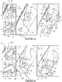
- FIGs of figures 1a to 1d illustrate an airplane emergency door profile 1 which moves in position relative to the profile of the fixed fuselage 2 of an airplane in order to illustrate the essential steps of the reversal opening kinematics according to the invention.
- the door 1 is in the closed position and the door profile 1 is then substantially aligned in the continuity of the fuselage profile 2 which surrounds it.
- the arrow F1a, for the upper edge of the door 1s, and the arrow F1b, for its lower edge 1i, indicate the direction and the orientation that the first so-called inclined lifting stage will impart to the door 1.
- the upper door edge 1s is moved towards the inside of the cabin C1 (arrow F1a) while the lower edge 1i moves substantially vertically upwards (arrows F1b).
- the figure 1b illustrates the position of the door 1 relative to the fuselage 2 following the movement made during the lifting step, with the edge 1s in the cabin C1 and the raised edge 1i facing the lower edge 2i of the fuselage 2.
- the exteriorization step which follows consists in translating the door 1 according to an inclination substantially identical to that of the lifting step but in the opposite direction (arrows F2a and F2b). This externalization step prepares the lower edge 1i in position outside the cabin C1 to proceed with the final pivoting under secure conditions.
- the pivoting of the door 1 can then begin with a rotation (arrow Rp) around a pivot axis A1 positioned close to the upper edge 2s of the fuselage 2.
- the pivoting step continues until that the door 1 has reached a maximum open position with respect to the profile of the fuselage 2, as illustrated in the figure 1d .
- FIGS. 2a and 2b illustrate the airplane emergency door 1 in the closed position, respectively from the exterior “E” of the fuselage 2 and from the interior of the cabin C1.
- the emergency door 1 includes a porthole 3 and is positioned in a cutout 10 made in the fuselage 2.
- a seal 4 (which also appears on the figure 3a and 4a to 4f , diagrams A and B) is attached to the edge of the door 1 and runs along the cutout 10 when the door is in the closed position.
- a waterproof box 40 houses an external opening control handle 41.
- the edges of the door 1 and of the fuselage 2 arranged facing each other around the cutout 10 respectively comprise door and fuselage frame beams, respectively, 11 and 21, which extend longitudinally and laterally, namely: two upper and lower longitudinal beams, 11a and 21a, as well as two front and rear side beams, respectively 11c and 21c, joining the corresponding longitudinal beams.
- the emergency door 1 opening system comprises an opening control handle 5 and a door opening mechanism 30.
- This mechanism 30 involves pivoting levers 6 and side door attachment fittings 12 arranged in the upper corner zones of the door Zs, located at the level of - or, alternatively, integrated with - the side beams of the door frame 11c.
- upper and lower guide paths, 20s and 20i are mounted on the side beams 21c of the fuselage frame 21 - close to their upper and lower ends - and facing the side beams 11c of the frame door 11.
- the figures 3a and 3b illustrate enlargements of the opening system according to partial perspective views, respectively located in the upper and lower corner zones, Zs and Zi, of the side beam 11c of the door frame 11 facing the side beam 21c of the fuselage 2.
- control handle 5 rotates (arrow F11) the shaft 5a which in turn drives the locking/unlocking latch 51 in combination with the locking/unlocking latch 52.
- lock 51 and latch 52 elements cooperate with the pivoting lever 6 - articulated in rotation by a support 6s fixed to the upper edge 2s of the fuselage 2 - to act on the fitting of door attachment 12 (cf. figures 4a to 4f ).
- An upper connecting guide, in the upper corner zones Zs, is produced between an upper roller Gs coming from the door attachment fitting 12 (or, alternatively, from the door frame side beam 11c acting as attachment fitting) and sliding in the upper guideway 20s mounted in the side beam 21c of the fuselage frame.
- a lower link guide is formed in the lower corner zones Zi, between the door 11c and fuselage 21c side beams by a lower roller Gi coming from the door side beam 11c to slide in the lower guide path 20i mounted in the side fuselage beam 21c opposite.
- a lower auxiliary abutment 7 is fixed to the junction angle of the side beams 11c and the longitudinal beam of the door frame 11a, and to the longitudinal beam of the fuselage frame 21a opposite.
- This lower auxiliary stop 7 makes it possible to overcome the rupture of the corresponding lower guide path 20i.
- An equivalent function is ensured in the upper location of the door 1 by the pivoting lever 6 to compensate for a break in the upper guide path 20s (cf. figure 2b ).
- each upper guideway 20s (diagram A), mounted on a transverse face 22 of the fuselage frame side beam 21c, has a slideway 22s formed of two linear portions, P1 and P2, which follow one another around the transition line “T”.
- the portions P1 and P2 have inclination slopes of the same sign and of slightly different amplitude: the portion P1 located towards the interior "I" of the cabin has a steeper slope - with respect to a horizontal line - than that of the portion P2 located towards the outside “E” of the fuselage 2.
- the difference in inclination amplitude between the portions P1 and P2 depends on the fuselage configurations, these portions possibly having the same inclination.
- the portion P1 ends inwards with a top stop Bs and the portion P2 with an opening Es towards the outside “E”.
- each slide 22i (diagram B) of the lower guide paths 20i, also mounted on the transverse face 22, has an elbow configuration with, from the inside "I” to the outside "E", a portion P3 substantially vertical from the internal bottom stop Bi, a vertex S1 forming a top stop and an inclined linear portion P4 ending in an opening Ei towards the outside "E".
- This portion P4 has a slope of inclination having a slightly lower amplitude (compared to a horizontal line) than that of the portion P2 of the upper slide 22s.
- the lock 51 has two wings 50a, terminated by two lugs 5E and 5F.
- the lug 5E is locked against the latch 52 and the lug 5F is close to the "vertical" portion of an "L" ramp R3 formed by the pivoting lever 6 which incorporates a cooperation guide path 23 ( diagram D).
- a face 52f of the latch 52 is blocked against a wall 23p connected to the ramp R3.
- the bolt 51 and the latch 52 are in the immobilization position (locking/blocking) of the door attachment fitting 12: lugs 12E of said fitting 12 are blocked halfway between windows F1, F2 formed in the cooperation guide path 23 of the pivoting lever 6.
- These lugs 12E also remain in this position in diagrams C and D of the figures 4b and 4c , i.e. as long as the opening mechanism is locked and/or blocked.
- an action on the control handle 5 results in unlocking without unlocking the opening system.
- the latch 51 has rotated around its axis of rotation 5x so that the lug 5E is in a position to be able to circulate in raceways R1 and R2 integrated into the latch 52.
- the lug 5F of the latch 51 remains close to the “vertical” portion of ramp R3 in the shape of an “L”.
- the latch 52 remains locked against the connected wall 23p of the ramp R3 of the pivot lever 6.
- the latch 52 is disengaged from the related blocking wall 23p following the rotation of the latch 52 in combination with that of the lock 51, the distance between their axes 5x and 5b being determined to achieve this combined rotation .
- the lug 5E of the latch 51 simultaneously enters the raceway R2 of the latch 52.
- the other lug 5F of the latch 51 slides along the "horizontal" portion of the "L" ramp R3 of the pivot lever 6 .
- the 4d figure illustrates the end of this lifting step towards the interior of the car to the reversal point.
- the upper roller Gs slides in the inwardly inclined portion "I" of the linear portion P1 (see diagram A of the figure 4a ) of the slide 22s until reaching the upper stop Bs (diagram A).
- the lower roller Gi reaches the top S1 of the lower slide 22i (diagram B).
- the positions of the rollers Gs and Gi in the slideways 22s and 22i correspond to a position of the lug 5F of the lock 51 at the end of sliding on the small side of the ramp R3 of the pivoting lever 6 (diagram C).
- the door attachment fitting 12 having followed the door lifting, the lugs 12E of this attachment fitting 12 reach or approach the upper stops B1 and B2 of the windows F1 and F2 of the cooperation path 23 (diagram D) of the pivoting lever 6.
- the opening mechanism has reached its reversal point, corresponding to the position of the roller Gs against the upper stop Bs.
- the step of exteriorizing the door then takes place by sliding in the opposite direction of the roller Gs and therefore backwards while the roller Gi continues its "elbow” movement around the vertex S1, respectively in the inclined portions P2 and P4 of slides 22s and 22i outwards “E” (diagrams A and B).
- the lug 5F of the lock 51 moves towards a slide 24 of the pivoting lever 6 which ends in a locking abutment B3 (diagrams C and D).
- the positions of the rollers Gs, Gi of the slides 22s and 22i and of the lugs 5E and 5F of the lock 51 are as illustrated by the figure 4e : the rollers Gs and Gi are found at the end of sliding inclined downwards, that is to say at the level of the openings in quasi disconnection of the slides 22s and 22i (diagrams A and B), and therefore ready to be released towards outside "E".
- the 5E latch lug comes out of the raceway R2 of the latch 52 and the 5F latch lug comes into position close to the locking abutment B3 of the pivoting lever 6.
- the pivoting of door 1 (cf. figure 2b ) is ready to engage, once the door attachment fitting 12 is locked on the pivot lever 6 as illustrated by the figure 4f .
- the rollers Gs, Gi are still at the level of the openings Es and Ei of the slides 22s and 22i (diagrams A and B)
- the lug 5F of the lock 51 is immobilized in the locking abutment B3 and its other lug 5E is blocked in abutment on the raceway R1 of the latch 52 (diagrams C and D): the attachment fitting 12 is secured to the pivoting lever 6 by this locking/blocking of the movement intermediaries, latch 51 combined with the latch 52.
- the pivot lever 6 will then drive the door attachment fitting 12 and therefore the door 1 in rotation around the pivot axis A1 of the pivot lever 6 (arrow F12).
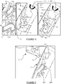
- the pivoting lever 6 opens the emergency door 1 to a maximum lifting position.
- the amplitude of the opening of the emergency door 1 can be appreciated by reference to the fuselage 2 and to the slide 22s of the upper connecting guide path 20s, also represented.
- the figure 6 From the perspective view coming from outside "E", the figure 6 also shows the emergency door 1 in the maximum open position with respect to the fuselage 2. This view also shows a compensation spring 8 - intended to balance, by its compression, the mass of the door 1 during its opening -, the door attachment fitting 12, the pivoting levers 6 and an upper guide path 20s connecting with the corresponding attachment fitting 12.
- the invention is not limited to the embodiments described and represented.
- other connecting guide paths between the door frame and fuselage side beams
- the number of movement intermediaries can be greater than two.
- the slopes of the slideways of the guide paths are adapted according to the configuration of the fuselage or the door.
Description
L'invention se rapporte à un procédé d'ouverture d'une porte de secours d'un avion, ainsi qu'à un système comportant un mécanisme entre la porte de secours et le fuselage d'un avion apte à mettre en œuvre un tel procédé. Une porte de secours d'un avion est située au-dessus de la voilure de l'avion (« overwing emergency exit door » en terminologie anglaise). En dehors de sa fonction d'évacuation des passagers en situation d'urgence, de telles portes peuvent être utilisées pour recevoir/sortir du matériel ou des marchandises.The invention relates to a method for opening an emergency door of an aircraft, as well as to a system comprising a mechanism between the emergency door and the fuselage of an aircraft capable of implementing such process. An emergency door of an aircraft is located above the wing of the aircraft (“overwing emergency exit door” in English terminology). Apart from its function of evacuating passengers in an emergency situation, such doors can be used to receive/exit equipment or goods.
De manière générale, l'ouverture d'une porte d'avion, par exemple d'une porte passagers ou d'urgence, peut se décomposer en plusieurs mouvements qui se succèdent: déverrouillage et libération d'un cran de sûreté, levage et pivotement de la porte par des actionneurs autour d'un axe de rotation. Pour la fermeture, ces mouvements se succèdent selon une cinématique inverse.In general, the opening of an aircraft door, for example a passenger or emergency door, can be broken down into several successive movements: unlocking and release of a safety catch, lifting and pivoting of the door by actuators around an axis of rotation. For closing, these movements follow one another according to an inverse kinematics.
Dans des situations d'urgence, il est recherché de pouvoir déclencher l'ouverture de la porte en un minimum d'opérations dans un minimum de temps tout en sécurisant l'ouverture.In emergency situations, it is desired to be able to trigger the opening of the door in a minimum of operations in a minimum of time while securing the opening.
La réglementation sécuritaire devient de plus en plus contraignante entraînant la mise en place de cinématiques complexes avec des moyens présentant des inconvénients substantiels, en particulier des bras d'articulation encombrants, coûteux et de masses non négligeables, ainsi que des bavettes d'étanchéité du fait de découpes additionnelles du fuselage pour réaliser le dégagement de la porte vers le haut ou vers le bas.Safety regulations are becoming more and more restrictive leading to the implementation of complex kinematics with means having substantial drawbacks, in particular cumbersome, expensive hinge arms with significant masses, as well as sealing flaps due to additional cutouts in the fuselage to make the door clearance upwards or downwards.
Il est par exemple connu du document de
Pour accompagner le mouvement de la porte, des actionneurs sont montés sur le fuselage en partie supérieure de porte pour exercer une poussée sur les bras d'articulation. Un amortisseur est également présent dans une position similaire pour réguler la vitesse de déplacement de la porte. En outre, afin de maintenir étanche la jonction entre l'intérieur et l'extérieur de l'avion, il est nécessaire de prévoir une bavette d'étanchéité en périphérie de porte qui vient en butée contre le fuselage.To accompany the movement of the door, actuators are mounted on the fuselage in the upper part of the door to exert a thrust on the hinge arms. A damper is also present in a similar position to regulate the speed of movement of the door. In addition, in order to keep the junction between the inside and the outside of the aircraft sealed, it is necessary to provide a sealing flap on the periphery of the door which comes into abutment against the fuselage.
Les ensembles de guidage de bras d'articulation et de guidage de cadre de porte définissent une cinématique d'ouverture de porte typique : en début de levage, les bords supérieur et inférieur de la porte se déplacent à la fois vers l'intérieur du fuselage et vers le haut.The hinge arm guide and door frame guide assemblies define a typical door opening kinematics: at the start of the lift, the upper and lower edges of the door move both inboard of the fuselage and upwards.
De manière générale, les portes de cabine utilisent des bavettes d'étanchéité pour leur jonction avec le fuselage, la bavette pouvant présenter un volet souple plaqué à l'extérieur du fuselage après avoir été précontraint en direction du fuselage, comme décrit dans le brevet
D'autres solutions, décrites par exemple dans les documents de brevet
L'invention vise à remédier à ces inconvénients de l'état de la technique à l'aide un système peu encombrant, sans bras d'articulation ni bavette d'étanchéité, sans nécessiter de cinématique complexe, tout en réalisant une ouverture sûre et efficace. En outre, le mécanisme peu encombrant de la présente invention va permettre de répondre au souhait des compagnies aériennes concernant la possibilité d'intégration dans la porte de secours d'un hublot de taille comparable à celle des autres hublots de la cabine.The invention aims to remedy these drawbacks of the state of the art by means of a space-saving system, without hinge arms or sealing flaps, without requiring complex kinematics, while achieving safe and effective opening. . In addition, the space-saving mechanism of this invention will make it possible to respond to the wishes of the airlines concerning the possibility of integration in the emergency door of a window of size comparable to that of the other windows of the cabin.
Pour ce faire, l'invention prévoit une ouverture de porte par un guidage latéral définissant une cinématique intégrée à rebroussement vers l'intérieur de la cabine pour le bord supérieur de la porte, puis vers l'extérieur du fuselage pour le bord inférieur avant de procéder à un levage par rotation.To do this, the invention provides for a door opening by a lateral guide defining an integrated kinematics with reversal towards the inside of the cabin for the upper edge of the door, then towards the outside of the fuselage for the lower forward edge of perform a rotational lift.
A ce titre, la présente invention a pour objet un procédé d'ouverture d'une porte de secours de cabine d'avion dans un fuselage selon la revendication 1 pour permettre une sortie d'urgence de la cabine de passagers. Le procédé consiste à effectuer une cinématique d'ouverture de porte agencée dans une découpe du fuselage, à partir d'un état initial de porte en position fermée de profil aligné avec le fuselage, selon la suite d'étapes suivantes, générées successivement par l'action d'une commande d'ouverture: une étape d'activation d'intermédiaires de mouvement tels que définis dans la revendication 1 pour déverrouiller et débloquer une transmission de commande, une étape de levage incliné en liaison avec le fuselage par un coulissement incliné des bords supérieur de la porte vers l'intérieur de cabine et un coulissement simultané d'élévation de son bord inférieur. Cette étape est suivie, par rebroussement de mouvement, d'une étape d'extériorisation du bord inférieur de porte hors de la cabine par un coulissement des bords de la porte en sens inverse et selon sensiblement une même inclinaison que celle du bord supérieur dans l'étape de levage, rétablissant simultanément le bord supérieur de la porte au niveau du fuselage, et une étape finale de pivotement de la porte par un verrouillage et un blocage de la transmission de commande sur la porte qui est alors entraînée, via la commande d'ouverture, en pivotement autour d'un axe de rotation longitudinal du fuselage. De plus, les coulissements sont réalisés par des guidages supérieurs et inférieurs de liaison entre des encadrements de la porte et du fuselage en regard, ainsi que par des guidages de coopération de la transmission de commande avec la porte.As such, the present invention relates to a method for opening an aircraft cabin emergency door in a fuselage according to
Dans ces conditions, les déplacements en « aller-retour » de la porte occupent un espace minimalisé sans découpe supplémentaire du fuselage, ce qui permet de réduire significativement la taille de la découpe de porte dans le fuselage et de s'affranchir des systèmes d'étanchéité à bavette pour la liaison porte- fuselage.Under these conditions, the "out and back" movements of the door occupy a minimal space without additional cutout of the fuselage, which makes it possible to significantly reduce the size of the door cutout in the fuselage and do away with flap sealing systems for the fuselage carrier connection.
Selon des modes de mise en œuvre préférés :
- l'étape d'activation des intermédiaires de mouvement sur la transmission de commande débute par une phase de déverrouillage produite par une rotation combinée des intermédiaires de mouvement à partir d'une position de verrouillage-blocage, ce déverrouillage entraînant un déblocage des guidages de coopération de la commande de transmission avec la porte et des guidages de liaison entre les encadrements ;
- l'étape de levage incliné de la porte est générée par des trajectoires simultanées vers l'intérieur de cabine des guidages supérieurs de liaison et vers le haut des guidages inférieurs de liaison, partant d'une position intermédiaire sur les guidages supérieurs et d'une position en butée basse sur les guidages inférieurs de liaison jusqu'à une position en butées hautes sur ces guidages de liaison définissant le rebroussement, alors qu'un coulissement de la porte se produit simultanément vers le haut dans le guidage de coopération de la transmission de commande jusqu'à une position de butée haute;
- dans l'étape d'extériorisation de la porte, les guidages supérieurs et inférieurs de liaison empruntent, en sens inverse et jusqu'à leur déconnexion, des trajectoires d'inclinaison inférieure ou égale à l'inclinaison des trajectoires des guidages supérieurs de liaison dans l'étape de levage et, simultanément, la porte coulisse vers le bas sur le guidage de coopération à partir de la position haute jusqu'à atteindre une butée basse puis, en fin de coulissement, le guidage de coopération de la porte est verrouillée-bloquée par les intermédiaires de mouvement en position de butée de verrouillage sur le guidage de coopération de la transmission de commande correspondant à la position initiale de pivotement; à la fin de la phase d'extériorisation, le bord inférieur de la porte est suffisamment dégagé vers l'extérieur de l'avion par rapport au fuselage de sorte que la phase de pivotement débute sans risque de contact;
- l'étape finale de pivotement de la porte débute par l'entraînement de la porte verrouillée-bloquée sur la transmission de commande par la commande d'ouverture autour de l'axe de rotation de la transmission de commande jusqu'à atteindre une position extrême prédéterminée;
- une compensation de masse de la porte est prévue afin d'équilibrer cette masse lors de l'étape finale de levage.
- the step of activating the movement intermediaries on the control transmission begins with an unlocking phase produced by a combined rotation of the movement intermediaries from a locking-locking position, this unlocking resulting in the unlocking of the cooperation guides the transmission control with the door and the connecting guides between the frames;
- the inclined lifting step of the door is generated by simultaneous trajectories towards the inside of the cabin of the upper connecting guides and upwards of the lower connecting guides, starting from an intermediate position on the upper guides and from a position in low stop on the lower link guides up to a position in high stops on these link guides defining the reversal, while a sliding of the door occurs simultaneously upwards in the cooperation guide of the transmission of control up to a high stop position;
- in the step of externalizing the door, the upper and lower connecting guides borrow, in the opposite direction and until they are disconnected, trajectories of inclination less than or equal to the inclination of the trajectories of the upper connecting guides in the lifting step and, simultaneously, the door slides downwards on the cooperation guide from the high position until reaching a low stop then, at the end of sliding, the cooperation guide of the door is locked- blocked by the movement intermediaries in the locking abutment position on the cooperation guide of the control transmission corresponding to the initial pivoting position; at the end of the exteriorization phase, the lower edge of the door is clear enough towards the outside of the airplane relative to the fuselage so that the pivoting phase begins without risk of contact;
- the final door pivoting stage begins with driving the locked-locked door onto the control transmission by the control opening around the axis of rotation of the control transmission until reaching a predetermined extreme position;
- a mass compensation of the door is provided in order to balance this mass during the final lifting stage.
L'invention se rapporte également à un système d'ouverture de porte de secours positionnée dans un fuselage d'avion selon la revendication 7, le système comportant des encadrements respectifs de porte et de fuselage qui s'étendent en regard, au moins un couple verrou/loquet, une ferrure d'attache de porte et des chemins de guidage supérieurs et inférieurs montés dans l'encadrement de fuselage.The invention also relates to an emergency door opening system positioned in an aircraft fuselage according to
Le système d'ouverture comporte également une poignée de mise en rotation combinée d'au moins le couple verrou/loquet de (dé)verrouillage / (dé)blocage, et un mécanisme d'ouverture équipé, dans au moins une zone d'angle supérieure de la porte, d'un levier de pivotement articulé en rotation sur un bord supérieur de fuselage et muni de chemins de guidage en coopération avec le couple verrou/loquet tel que définis dans la revendication 7 et avec la ferrure d'attache de porte, de galets de guidage supérieurs et inférieurs montés dans l'encadrement latéral de porte pour former des moyens de guidage en liaison avec des chemins de guidage correspondants montés dans l'encadrement de fuselage en regard, les chemins de guidage supérieurs étant globalement inclinés en montant et les chemins de guidage inférieurs coudés. De plus, chaque chemin de guidage supérieur présente deux portions de glissière consécutives sensiblement linéaires dans lesquels circulent respectivement les galets venant de la poutre latérale d'encadrement de porte correspondante et chaque chemin de guidage inférieur présente une configuration de coudage avec un sommet.The opening system also comprises a handle for rotation combined with at least the lock/latch pair for (un)locking/(un)blocking, and an opening mechanism equipped, in at least one corner zone upper part of the door, of a pivoting lever hinged in rotation on an upper edge of the fuselage and provided with guide paths in cooperation with the lock/latch couple as defined in
De préférence, les chemins de guidage supérieurs présentent une butée interne d'extrémité haute et des portions sensiblement linéaires et inclinées jusqu'à une ouverture d'extrémité externe basse, et les chemins de guidage inférieurs présentent une butée basse d'extrémité interne couplée à une portion sensiblement verticale pourvue d'un sommet et prolongée par une portion sensiblement linéaire d'extrémité ouverte vers l'extérieur selon une inclinaison de pente inférieure à celles des portions des chemins de guidage supérieurs.Preferably, the upper guide paths have an internal upper end stop and substantially linear and inclined portions up to a lower outer end opening, and the lower guide paths have a lower inner end stop coupled to a substantially vertical portion provided with a vertex and extended by a substantially linear portion with an open end towards the outside according to an inclination with a slope less than those of the portions of the upper guide paths.
Selon des modes de réalisation particulièrement avantageux :
- le (chaque) levier de pivotement présente un chemin de guidage en coopération avec des ergots venant de la ferrure d'attache de porte, ce chemin de guidage présentant des rebords qui servent de rampe au verrou et au loquet;
- l'encadrement de porte présente des côtés latéraux qui sont solidaires ou qui intègrent les ferrures d'attache de porte;
- un ressort de compensation de masse de la porte est monté sur l'axe de rotation du levier de pivotement afin d'équilibrer la masse de la porte lors du pivotement;
- des butées auxiliaires sont fixées à l'angle de jonction des poutres latérales et de la poutre longitudinale d'encadrement de porte et à la poutre longitudinale d'encadrement de fuselage en regard, pour pallier une rupture de chemin de guidage supérieur.
- the (each) pivoting lever has a guide path in cooperation with lugs coming from the door attachment fitting, this guide path having flanges which serve as a ramp for the bolt and the latch;
- the door frame has lateral sides which are integral with or which integrate the door attachment fittings;
- a door mass compensation spring is mounted on the axis of rotation of the pivoting lever in order to balance the mass of the door during pivoting;
- auxiliary stops are fixed to the angle of junction of the side beams and the longitudinal beam of the door frame and to the longitudinal beam of the opposite fuselage frame, to compensate for a break in the upper guide path.
L'invention se rapporte à une porte de secours de cabine d'avion dans un fuselage comportant un système d'ouverture tel que défini cidessus.The invention relates to an aircraft cabin emergency door in a fuselage comprising an opening system as defined above.
Dans le présent texte, le terme « galet » désigne aussi bien une pièce de roulement mobile en rotation lors de son déplacement sur une rampe ou dans un chemin de came, glissière, piste ou équivalent, qu'un doigt non rotatif, se déplaçant en translation. « Vertical » ou « horizontal » qualifie une direction parallèle à la direction de la gravité terrestre ou respectivement dans un plan perpendiculaire à cette direction. Les qualificatifs « supérieur » et « inférieur » se réfèrent à une localisation respectivement au-dessus et en-dessous du hublot de la porte. Le qualificatif « longitudinal » se réfère à la direction principale du fuselage de l'avion, « avant » et « arrière » aux qualificatifs usuels de localisation dans un avion, à savoir du côté du cockpit et du côté de la queue d'un avion. « Transversal » qualifie une étendue dans un plan perpendiculaire à la direction longitudinale du fuselage et « latéral » une étendue dans le fuselage selon une direction perpendiculaire à la direction longitudinale. Par ailleurs, des extrémités ou butées respectivement « haute » ou « basse » se réfèrent à une position relative la plus élevée ou la moins élevée dans un même élément, au sens de la plus éloignée ou la moins éloignée du sol. Les qualificatifs « montant » ou « descendant » signifient en déplacement vers le haut, c'est-à-dire en s'éloignant du sol, ou respectivement vers le bas en s'y rapprochant. De plus, « extérieur » ou « externe » (respectivement « intérieur » ou « interne ») qualifie une localisation située à l'extérieur (respectivement à l'intérieur) de la cabine d'avion, en d'autres termes hors (respectivement à l'intérieur) du fuselage de l'avion.In the present text, the term "roller" designates both a rotating rolling part during its movement on a ramp or in a cam track, slide, track or equivalent, as well as a non-rotating finger, moving in translation. "Vertical" or "horizontal" qualifies a direction parallel to the direction of Earth's gravity or respectively in a plane perpendicular to this direction. The qualifiers “upper” and “lower” refer to a location respectively above and below the door window. The qualifier "longitudinal" refers to the main direction of the fuselage of the aircraft, "front" and "rear" to the usual qualifiers of location in an aircraft, namely the side of the cockpit and the side of the tail of an aircraft . "Transversal" qualifies an extent in a plane perpendicular to the longitudinal direction of the fuselage and "lateral" an extent in the fuselage in a direction perpendicular to the longitudinal direction. Furthermore, respectively “high” or “low” ends or abutments refer to a highest or lowest relative position in the same element, in the sense of furthest or least distant from the ground. The qualifiers "rising" or "descending" mean moving upwards, that is to say away from the ground, or respectively down while approaching it. In addition, "exterior" or "external" (respectively "interior" or "internal") qualifies a location located outside (respectively inside) of the aircraft cabin, in other words outside (respectively inside) of the aircraft fuselage.
D'autres données, caractéristiques et avantages de la présente invention apparaîtront à la lecture de la description non limitée qui suit, en référence aux figures annexées qui représentent, respectivement :
- les
figures 1a à 1d , des schémas de profil d'une porte de secours d'avion par rapport au profil du fuselage illustrant les étapes essentielles de la cinématique d'ouverture à rebroussement selon l'invention; - les
figures 2a et 2b , des vues en perspective de la porte de secours d'avion en position fermée, respectivement à partir de l'extérieur du fuselage et de l'intérieur de la cabine d'avion; - les
figures 3a et 3b , des agrandissements en perspective d'un exemple de système d'ouverture de porte selon l'invention tel que localisé en vues partielles sur des poutres latérales de l'encadrement de porte et du fuselage en regard ; - les
figures 4a à 4f , des vues en coupe dans des plans transversaux des guidages de liaison (schémas A et B) et des guidages de coopération (schémas C et D) de ce système d'ouverture mis en œuvre depuis l'état de verrouillage jusqu'à l'ouverture maximale de la porte, entre des instants de verrouillage / blocage (figure 4a ), de déverrouillage (figure 4b ), déblocage (figure 4c ), de levage jusqu'au point de rebroussement (figure 4d ), en fin d'extériorisation (figure 4e ) et en prise de pivotement (figure 4f ); - la
figure 5 , une vue en coupe partielle de la porte en position de levage maximale, dans le plan transversal du schéma D, et - la
figure 6 , une vue en perspective externe de la porte de secours en position de levage maximale.
- them
figures 1a to 1d , profile diagrams of an airplane emergency door in relation to the profile of the fuselage illustrating the essential steps of the reversal opening kinematics according to the invention; - them
figures 2a and 2b , perspective views of the aircraft emergency door in the closed position, respectively from outside the fuselage and inside the aircraft cabin; - them
figures 3a and 3b , perspective enlargements of an example of a door opening system according to the invention as located in partial views on the side beams of the door frame and of the facing fuselage; - them
figures 4a to 4f , cross-sectional views in transverse planes of the connecting guides (diagrams A and B) and of the cooperation guides (diagrams C and D) of this opening system implemented from the locking state to the maximum opening of the door, between locking/blocking instants (figure 4a ), unlock (figure 4b ), unlock (figure 4c ), lifting to the cusp point (4d figure ), at the end of exteriorization (figure 4e ) and in pivoting gear (figure 4f ); - the
figure 5 , a partial sectional view of the door in the maximum lift position, in the transverse plane of diagram D, and - the
figure 6 , an external perspective view of the emergency door in the fully raised position.
Sur les figures, des signes de référence identiques renvoient à un même élément ainsi qu'aux passages de la description correspondants.In the figures, identical reference signs refer to the same element as well as to the corresponding passages of the description.
Les schémas des
Sur le schéma de la
La
En effet, à la fin de l'étape d'extériorisation (
Le pivotement de la porte 1 (étape de pivotement) peut alors commencer par une rotation (flèche Rp) autour d'un axe de pivotement A1 positionné à proximité du bord supérieur 2s du fuselage 2. L'étape de pivotement se poursuit jusqu'à ce que la porte 1 ait atteint une position d'ouverture maximale par rapport au profil du de fuselage 2, comme illustré sur la
De manière plus réaliste, les vues en perspective des
La porte de secours 1 comporte un hublot 3 et est positionnée dans une découpe 10 réalisée dans le fuselage 2. Un joint d'étanchéité 4 (qui apparaît également sur les
A l'intérieur de la cabine C1, les bords de porte 1 et de fuselage 2 disposés en regard autour de la découpe 10 comportent respectivement des poutres d'encadrements de porte et de fuselage, respectivement, 11 et 21, qui s'étendent longitudinalement et latéralement, à savoir: deux poutres longitudinales supérieures et inférieures, 11a et 21a, ainsi que deux poutres latérales avant et arrière, respectivement 11c et 21c, joignant les poutres longitudinales correspondantes.Inside the cabin C1, the edges of the
Le système d'ouverture de la porte de secours 1 comporte une poignée de commande d'ouverture 5 et un mécanisme d'ouverture de porte 30. Ce mécanisme 30 fait intervenir des leviers de pivotement 6 et des ferrures d'attache latérales de porte 12 agencées dans les zones d'angle supérieures de porte Zs, localisées au niveau des - ou, alternativement, intégrées aux - poutres latérales d'encadrement de porte 11c.The
De plus, des chemins de guidage supérieurs et inférieurs, 20s et 20i, sont montés sur les poutres latérales 21c de l'encadrement de fuselage 21 - à proximité de leurs extrémités supérieures et inférieures - et en regard des poutres latérales 11c de l'encadrement de porte 11.In addition, upper and lower guide paths, 20s and 20i, are mounted on the side beams 21c of the fuselage frame 21 - close to their upper and lower ends - and facing the side beams 11c of the
Les
En référence à la
Ces éléments de verrou 51 et de loquet 52, également appelés « intermédiaires de mouvement », coopèrent avec le levier de pivotement 6 - articulé en rotation par un support 6s fixé sur le bord supérieur 2s du fuselage 2 - pour agir sur la ferrure d'attache de porte 12 (cf.
En référence à la
De plus, une butée auxiliaire inférieure 7 est fixée à l'angle de jonction des poutres latérales 11c et de la poutre longitudinale d'encadrement de porte 11a, et à la poutre longitudinale d'encadrement de fuselage 21a en regard. Cette butée auxiliaire inférieure 7 permet de pallier la rupture du chemin de guidage inférieur 20i correspondant. Une fonction équivalente est assurée en localisation supérieure de la porte 1 par le levier de pivotement 6 pour pallier une rupture de chemin de guidage supérieur 20s (cf.
Le système d'ouverture de porte de secours est maintenant décrit de manière détaillée par les vues en coupe des
En référence aux schémas A et B des
Plus précisément, chaque chemin de guidage supérieur 20s (schéma A), monté sur une face transversale 22 de poutre latérale d'encadrement de fuselage 21c, présente une glissière 22s formée de deux portions linéaires, P1 et P2, qui se succèdent autour de la ligne de transition « T ». Les portions P1 et P2 ont des pentes d'inclinaison de même signe et d'amplitude légèrement différente: la portion P1 située vers l'intérieur « I » de cabine possède une pente plus inclinée - par rapport à une ligne horizontale - que celle de la portion P2 située vers l'extérieur « E » du fuselage 2. La différence d'amplitude d'inclinaison entre les portions P1 et P2 dépend des configurations de fuselage, ces portions pouvant avoir une même inclinaison. La portion P1 se termine vers l'intérieur par une butée haute Bs et la portion P2 par une ouverture Es vers l'extérieur « E ».More specifically, each
En outre, chaque glissière 22i (schéma B) des chemins de guidage inférieur 20i, montés également sur la face transversale 22, présente une configuration en coude avec, de l'intérieur « I » vers l'extérieur « E », une portion P3 sensiblement verticale à partir de la butée basse interne Bi, un sommet S1 formant une butée haute et une portion P4 linéaire inclinée se terminant par une ouverture Ei vers l'extérieur « E ». Cette portion P4 présente une pente d'inclinaison ayant une amplitude légèrement plus faible (par rapport à une ligne horizontale) que celle de la portion P2 de la glissière supérieure 22s.In addition, each
Sur les schémas C et D de la
Le verrou 51 présente deux ailes 50a, terminées par deux ergots 5E et 5F. L'ergot 5E est bloqué contre le loquet 52 et l'ergot 5F est à proximité de la portion « verticale » d'une rampe R3 en « L » formée par le levier de pivotement 6 qui intègre un chemin de guidage de coopération 23 (schéma D). Une face 52f du loquet 52 est bloquée contre une paroi 23p connexe à la rampe R3. Ainsi, le verrou 51 et le loquet 52 sont en position d'immobilisation (verrouillage/blocage) de la ferrure d'attache de porte 12: des ergots 12E de ladite ferrure 12 sont bloqués à mi-chemin de fenêtres F1, F2 formées dans le chemin de guidage de coopération 23 du levier de pivotement 6. Ces ergots 12E restent également dans cette position sur les schémas C et D des
En référence aux schémas C et D de la
Sur la
Suite au déblocage, le mécanisme d'ouverture se poursuit par l'étape de levage inclinée de porte via celle de la ferrure d'attache 12. La
Les positions des galets Gs et Gi dans les glissières 22s et 22i correspondent à une position de l'ergot 5F du verrou 51 en fin de glissement sur le petit côté de la rampe R3 du levier de pivotement 6 (schéma C). La ferrure d'attache de porte 12 ayant suivie le levage de porte, les ergots 12E de cette ferrure d'attache 12 atteignent ou se rapprochent des butées hautes B1 et B2 des fenêtres F1 et F2 du chemin de coopération 23 (schéma D) du levier de pivotement 6. Le mécanisme d'ouverture a atteint son point de rebroussement, correspondant à la position du galet Gs contre la butée haute Bs.The positions of the rollers Gs and Gi in the
En effet, l'étape d'extériorisation de la porte se déroule ensuite par coulissement en sens inverse du galet Gs et donc en rebroussement alors que le galet Gi poursuit son mouvement « coudé » autour du sommet S1, respectivement dans les portions inclinées P2 et P4 des glissières 22s et 22i vers l'extérieur « E » (schémas A et B). Simultanément, l'ergot 5F du verrou 51 se dirige vers une glissière 24 du levier de pivotement 6 qui se termine par une butée de verrouillage B3 (schémas C et D).Indeed, the step of exteriorizing the door then takes place by sliding in the opposite direction of the roller Gs and therefore backwards while the roller Gi continues its "elbow" movement around the vertex S1, respectively in the inclined portions P2 and P4 of
A la fin de l'étape d'extériorisation, les positions des galets Gs, Gi des glissières 22s et 22i et des ergots 5E et 5F du verrou 51 se présentent comme illustrées par la
L'ergot de verrou 5E sort du chemin de roulement R2 du loquet 52 et l'ergot de verrou 5F vient se positionner à proximité de la butée de verrouillage B3 du levier de pivotement 6. La porte 1 (cf.
Suite à l'étape d'externalisation, le pivotement de la porte 1 (cf.
Le levier de pivotement 6 va alors entraîner la ferrure d'attache de porte 12 et donc la porte 1 en rotation autour de l'axe de pivotement A1 du levier de pivotement 6 (flèche F12). Comme illustré par la vue en coupe partielle de la
A partir de la vue en perspective venant de l'extérieur « E », la
L'invention n'est pas limitée aux exemples de réalisation décrits et représentés. Ainsi, d'autres chemins de guidage de liaison (entre les poutres latérales d'encadrement de porte et de fuselage) peuvent être utilisés en configuration et en nombre. Par ailleurs, le nombre d'intermédiaires de mouvement peut être supérieur à deux. Les pentes des glissières des chemins de guidage sont adaptées en fonction de la configuration du fuselage ou de la porte.The invention is not limited to the embodiments described and represented. Thus, other connecting guide paths (between the door frame and fuselage side beams) can be used in configuration and in number. Furthermore, the number of movement intermediaries can be greater than two. The slopes of the slideways of the guide paths are adapted according to the configuration of the fuselage or the door.
Claims (13)
- Method for opening an emergency door (1) of an aircraft cabin (C1) in a fuselage (2) according to opening kinematics for a door arranged in a cutout (10) in the fuselage (2), from an initial door (1) state in the closed position, with a profile aligned with the fuselage (2), such that it consists in carrying out the following succession of steps, generated in succession by the action of an opening control (5): a step of activation of intermediary movement units (51, 52), in order to unlock and unblock a pivoting control transmission (6) via a combined rotation between these intermediary movement units (51, 52), comprising a first (51) and a second (52) intermediary movement unit, respectively for locking/unlocking and for blocking/unblocking, the first intermediary unit (51) having a locking function which can be released from the second intermediary unit (52), and the second unit (52) having a function of blocking the access to movement, which is released when the first intermediary unit (51) has been disarmed, and these intermediary movement units (51, 52) having longitudinal axes of rotation (5x, 5b) supported by the door (1), at a distance which is designed to allow this combined rotation, a step of inclined lifting thus generated in association with the fuselage (2), by means of inclined sliding of the upper edge (1s) of the door (1) towards the interior of the cabin (I), and simultaneously lifting and sliding of its lower edge (1i), followed, by means of doubling-back of movement, by a step of exteriorization of the lower edge (1i) of the door outside the cabin (C1), by inclined sliding of the upper and lower edges (1s, 1i) of the door (1) in the inverse direction, and according to an inclination which is substantially the same as that of the upper edge (1s) in the lifting step, repositioning the upper edge (1s) of the door (1) simultaneously at the fuselage (2), and a final step of pivoting of the door (1) by means of locking and blocking of the control transmission (6) on the door (1), which is then pivoted around a longitudinal axis of rotation of the fuselage (A1), with the slidings being created by upper (20s) and lower (20i) guides for connection between frameworks (11, 21) of the door (1) and of the fuselage (2) opposite, as well as by guides (12E, 23) for cooperation of the control transmission (6) with the door (1).
- Opening method according to Claim 1, wherein the step of activation of the intermediary movement units (51, 52) on the control transmission (6) starts with a phase of unlocking caused by combined rotation of the intermediary movement units (51, 52) from a locking/blocking position, with this unlocking giving rise to unblocking of the guides (23, 12E) for cooperation of the control transmission (6) with the door (1) and of the guides (Gs, 20s; Gi, 20i) for connection between the frameworks (11, 21).
- Opening method according to either one of the preceding claims, wherein the step of inclined lifting of the door (1) is generated by simultaneous trajectories towards the interior of the cabin (P1) of the upper connection guides (20s), and upwards (P3) of the lower connection guides (20i), starting from an intermediary position (T) on the upper guides (20s), and from a low abutment position (Bi) on the lower connection guides (20i), as far as a high abutment position (Bs, S1) on these connection guides (20s, 20i) defining the doubling-back, whereas sliding of the door (1) occurs simultaneously in the cooperation guide (23, 12E) of the control transmission (6) as far as a high abutment position (B1, B2).
- Opening method according to any one of the preceding claims, wherein, in the step of exeriorization of the door (1), the upper (20s) and lower (20i) connection guides follow, in the inverse direction and as far as their disconnection (Es, Ei), inclination trajectories (P2, P4) which are smaller than, or equal to, the inclination of the trajectories (P1) of the upper connection guides (20s) in the lifting step, and, simultaneously, the door (1) slides downwards on the cooperation guide (23) from the high position (B1, B2), until it reaches a low abutment (B4, B5), then, at the end of sliding, the cooperation guide (23) of the door (1) on the control transmission (6) is locked/blocked by the intermediary movement units (51, 52) in the position of locking abutment (B3), corresponding to the initial position of pivoting of the door (1).
- Opening method according to any one of the preceding claims, wherein the final step of pivoting of the door (1) starts by driving of the locked/blocked door (1) on the control transmission (6) by the opening control (5) around the axis of rotation (A1) of the control transmission (6), until a predetermined end position is reached.
- Opening method according to any one of the preceding claims, wherein compensation for the mass (8) of the door (1) is provided in order to balance this mass during the final lifting step.
- System for opening an emergency door (1) positioned in an aircraft fuselage (2) for implementing the method according to any one of the preceding claims, this system comprising respective door and fuselage frameworks (11, 21) which extend opposite, at least one bolt/latch pair (51, 52), a door attachment fitting (12), and upper and lower guide tracks fitted in the framework of the fuselage (21), this opening system being such that it comprises a control handle (5) for combined rotation of at least the (un)locking/(un)blocking bolt/latch pair (51, 52), and an opening mechanism (30), which is equipped in at least one upper corner area (Zs) of the door (1) with a pivoting lever (6) which is articulated in rotation (A1) on an upper edge of the fuselage (2s), and is provided with tracks (23; F1, F2; 23p, 24) for guiding with slides in cooperation with the bolt/latch pair (51, 52) and with the door attachment fitting (12), the bolt (51) having two end lugs (5E, 5F), i.e. a lug (5E) which can circulate in guide tracks (R1, R2) integrated in the latch (52), and a lug (5F) which can slide on a ramp portion (R3) with a configuration which ends in a locking abutment (B3), with the latch (52) having a face (52f) which can cooperate with a connected wall (23p) of a ramp (R3) of the pivoting lever (6), with upper (Gs) and lower (Gi) rollers fitted in the lateral framework of the door (11c) in order to form means for guiding in association with corresponding guide tracks (20s, 22s; 20i, 22i) fitted in the fuselage framework (21c) opposite, with the upper guide tracks (20s, 22s) being globally inclined in a rising manner towards the interior of the cabin (I), and the lower guide tracks (20, 22i) being curved, and such that each upper guide track (20s) has two substantially linear consecutive slide portions (P1, P2) in which the rollers (Gs) obtained from the corresponding lateral beam (11c) of the door framework (11) respectively circulate, and each lower guide track (22i) has a curved configuration (P3, P4) with a top (S1).
- Opening system according to the preceding claim, wherein the upper guide tracks (20s, 22s) have a high end inner abutment (Bs) and portions (P1, P2) which are substantially linear and inclined as far as a low outer end opening (Es), and the lower guide tracks (20i, 22i) have a low inner end abutment (Bi) which is coupled with a substantially vertical portion (P3) provided with a top (S1) and extended by a substantially linear portion (P4) with an end (Ei) which is open towards the exterior (E) according to an inclination with a gradient smaller than that of the portions (P1, P2) of the upper guide tracks (20s, 22s).
- Opening system according to either one of Claims 7 and 8, wherein the (each) pivoting lever (6) has a guide track (23) in cooperation with lugs (12E) obtained from the door attachment fitting (12), with this guide track (23) having rims which act as a ramp (R3, 23p) for the bolt (51) and the latch (52).
- Opening system according to any one of Claims 7 to 9, wherein the door framework (11) has lateral sides (11c) which are integral with, or which incorporate, the door attachment fittings (12).
- Opening system according to any one of Claims 7 to 10, wherein a spring (8) for compensation for the mass of the door (1) is fitted on the axis of rotation (A1) of the pivoting lever (6), in order to balance the mass of the door (1) during the pivoting.
- Opening system according to any one of Claims 7 to 11, wherein auxiliary abutments (7) are secured at the corner of joining of the lateral beams (11c) and of the door framework longitudinal beam (11a), and at the fuselage framework longitudinal beam (21a) opposite.
- Emergency door (1) of an aircraft cabin (C1) in a fuselage (2), characterized in that it comprises an opening system according to any one of Claims 7 to 12.
Applications Claiming Priority (2)
| Application Number | Priority Date | Filing Date | Title |
|---|---|---|---|
| FR1559413A FR3041929B1 (en) | 2015-10-02 | 2015-10-02 | METHOD AND SYSTEM FOR OPENING AIRCRAFT EMERGENCY DOOR |
| PCT/IB2016/055837 WO2017056036A1 (en) | 2015-10-02 | 2016-09-29 | Opening system and method for an aircraft emergency door |
Publications (2)
| Publication Number | Publication Date |
|---|---|
| EP3356221A1 EP3356221A1 (en) | 2018-08-08 |
| EP3356221B1 true EP3356221B1 (en) | 2022-12-21 |
Family
ID=54848743
Family Applications (1)
| Application Number | Title | Priority Date | Filing Date |
|---|---|---|---|
| EP16788220.8A Active EP3356221B1 (en) | 2015-10-02 | 2016-09-29 | Process and system for opening an emergency aircraft door |
Country Status (4)
| Country | Link |
|---|---|
| US (1) | US11198498B2 (en) |
| EP (1) | EP3356221B1 (en) |
| FR (1) | FR3041929B1 (en) |
| WO (1) | WO2017056036A1 (en) |
Families Citing this family (9)
| Publication number | Priority date | Publication date | Assignee | Title |
|---|---|---|---|---|
| FR3067701B1 (en) * | 2017-06-18 | 2019-07-19 | Latecoere | METHOD FOR OPENING / CLOSING A MOBILE AIRCRAFT DOOR PANEL AND DOOR EQUIPPED WITH SUCH A MOBILE PANEL |
| CN107724859B (en) * | 2017-09-30 | 2019-02-12 | 中国航空工业集团公司西安飞机设计研究所 | A kind of ladder unification landing gate two-part curve driving mechanism |
| US20220162893A1 (en) * | 2019-03-20 | 2022-05-26 | Scandinavian Cargoloading Technologies Ab | Cargo door operating method and device |
| USD913195S1 (en) * | 2019-05-24 | 2021-03-16 | Alakai Technologies Corporation | Set of aircraft sliding side doors |
| EP3792174B1 (en) * | 2019-09-11 | 2023-01-04 | Rohr Inc. | Door mechanism |
| FR3104134B1 (en) * | 2019-12-07 | 2021-12-10 | Latecoere | Aircraft door with adjustable door fitting fixings |
| EP3967595B1 (en) * | 2020-09-15 | 2023-04-26 | The Boeing Company | Overwing exit door system |
| BR102021018231A2 (en) * | 2020-11-05 | 2022-05-17 | The Boeing Company | Coaxial Pressure Lock Assembly |
| CN112550661B (en) * | 2020-12-17 | 2022-04-08 | 中航沈飞民用飞机有限责任公司 | Civil aircraft semi-plugging type wing upper emergency cabin door |
Family Cites Families (10)
| Publication number | Priority date | Publication date | Assignee | Title |
|---|---|---|---|---|
| US4720065A (en) * | 1985-01-24 | 1988-01-19 | The Boeing Company | Translatable outward opening plug-type aircraft door and actuating mechanisms therefor |
| US5064147A (en) * | 1990-02-12 | 1991-11-12 | The Boeing Company | Upwardly opening plug-type door for use as an over-wing emergency hatch |
| US5305969A (en) * | 1991-07-16 | 1994-04-26 | The Boeing Company | Aircraft door latch lock mechanism |
| US5687452A (en) * | 1995-05-02 | 1997-11-18 | The Boeing Company | Hydraulic snubber for aircraft |
| US5931415A (en) * | 1997-05-09 | 1999-08-03 | The Boeing Company | Plug-type overwing emergency exit door assembly |
| FR2830564B1 (en) | 2001-10-05 | 2003-12-26 | Airbus France | DEVICE AND METHOD FOR CONTROLLING THE EMERGENCY OPENING OF AN AIRCRAFT EXHAUST DOOR |
| FR2975966B1 (en) | 2011-05-31 | 2013-06-14 | Latecoere | AIRCRAFT COMPRISING A CABIN DELIMITED BY A FUSELAGE COMPRISING AT LEAST ONE OPENING OF ACCESS TO THE CABIN, AND A DEVICE FOR SHUTTING OFF THIS OPENING. |
| CN104144851B (en) * | 2012-02-29 | 2017-05-17 | 庞巴迪公司 | Coupling assembling for aircraft door |
| FR3018064B1 (en) * | 2014-03-01 | 2018-02-23 | Latecoere | METHOD FOR OPENING / CLOSING AN AIRCRAFT CABIN DOOR AND CABIN DOOR ASSEMBLY SYSTEM IN AIRCRAFT FUSELAGE |
| US11077937B1 (en) * | 2018-06-22 | 2021-08-03 | Transcend Air Corporation | Vertical take-off and landing (VTOL) tilt-wing passenger aircraft |
-
2015
- 2015-10-02 FR FR1559413A patent/FR3041929B1/en active Active
-
2016
- 2016-09-29 WO PCT/IB2016/055837 patent/WO2017056036A1/en active Application Filing
- 2016-09-29 US US15/764,065 patent/US11198498B2/en active Active
- 2016-09-29 EP EP16788220.8A patent/EP3356221B1/en active Active
Also Published As
| Publication number | Publication date |
|---|---|
| US11198498B2 (en) | 2021-12-14 |
| US20180273156A1 (en) | 2018-09-27 |
| FR3041929B1 (en) | 2018-08-17 |
| WO2017056036A1 (en) | 2017-04-06 |
| EP3356221A1 (en) | 2018-08-08 |
| FR3041929A1 (en) | 2017-04-07 |
Similar Documents
| Publication | Publication Date | Title |
|---|---|---|
| EP3356221B1 (en) | Process and system for opening an emergency aircraft door | |
| EP3863921B1 (en) | Method for opening/closing an aircraft door and aircraft implementing such a method | |
| EP3983289B1 (en) | Aircraft door with a device for fixing the door manipulator arms | |
| FR2901245A1 (en) | Door articulating device for aircraft`s nacelle, has telescopic arm connected to nacelle and door by pivoting axles, respectively, where axles are parallel, and movement of center of gravity of door is situated in horizontal plane | |
| FR2901244A1 (en) | DEVICE FOR JOINING DOORS OF AN AIRCRAFT NACELLE AND NACELLE EQUIPPED WITH SAID ARTICULATION DEVICE | |
| WO2015132167A1 (en) | Method for opening and closing an aircraft cabin door and system for mounting a cabin door in an aircraft fuselage | |
| EP1784312B1 (en) | Motor vehicle comprising a sliding door and means for retaining the sliding door upon impact | |
| CA3003933A1 (en) | Aircraft emergency exit door with integrated mechanisms and method for opening/closing such a door | |
| EP2989004B1 (en) | Landing gear bay | |
| EP3678879B1 (en) | Mechanism for a motor vehicle trunk with two opening panels | |
| WO2004075620A2 (en) | Retractable roof device and vehicle fitted with said device | |
| WO2015124685A2 (en) | Glass roof having a movable panel which tilts and slides into a deflecting position | |
| EP1594382B1 (en) | Retractable roof and vehicle fitted with said device | |
| WO2005080107A1 (en) | Vehicle comprising a sunroof and a hatch | |
| EP1594711B1 (en) | Retractable roof device and vehicle fitted with said device | |
| EP1594708B1 (en) | Method for mounting a retractable roof and vehicle fitted with said roof | |
| EP3830369A1 (en) | Device for guiding a door of a vehicle | |
| EP1323558B1 (en) | Powered closing unit of an opening of a vehicle and corresponding vehicle | |
| WO2005108191A1 (en) | Vehicle comprising mobile centre pillars and storage method | |
| EP1598513A1 (en) | Vehicle door with sliding window panel. | |
| FR3077243A1 (en) | Carrier carriage having different door shapes for the driver's cab and construction system for producing a driver's cab of a transporter carriage | |
| FR2902046A1 (en) | Soft top vehicle, has arms extending on both sides of front elements, where front elements are displaced from front to back and back to front along arms so that front elements are brought back to rear element`s top in storage position | |
| FR2983129A1 (en) | Glazed roof for car, has mobile panel guided by two guide rails, where portion of mobile panel is arranged close to distal end, and another portion of mobile panel is arranged close to stationary proximal end | |
| FR2880588A1 (en) | SLIDING DOOR FOR MOTOR VEHICLE AND CORRESPONDING MOTOR VEHICLE | |
| FR3130698A1 (en) | Motor vehicle body provided with an opening receiving an opening hinged between a low closed position and a high open position |
Legal Events
| Date | Code | Title | Description |
|---|---|---|---|
| STAA | Information on the status of an ep patent application or granted ep patent |
Free format text: STATUS: UNKNOWN |
|
| STAA | Information on the status of an ep patent application or granted ep patent |
Free format text: STATUS: THE INTERNATIONAL PUBLICATION HAS BEEN MADE |
|
| PUAI | Public reference made under article 153(3) epc to a published international application that has entered the european phase |
Free format text: ORIGINAL CODE: 0009012 |
|
| STAA | Information on the status of an ep patent application or granted ep patent |
Free format text: STATUS: REQUEST FOR EXAMINATION WAS MADE |
|
| 17P | Request for examination filed |
Effective date: 20180406 |
|
| AK | Designated contracting states |
Kind code of ref document: A1 Designated state(s): AL AT BE BG CH CY CZ DE DK EE ES FI FR GB GR HR HU IE IS IT LI LT LU LV MC MK MT NL NO PL PT RO RS SE SI SK SM TR |
|
| AX | Request for extension of the european patent |
Extension state: BA ME |
|
| DAV | Request for validation of the european patent (deleted) | ||
| DAX | Request for extension of the european patent (deleted) | ||
| STAA | Information on the status of an ep patent application or granted ep patent |
Free format text: STATUS: EXAMINATION IS IN PROGRESS |
|
| 17Q | First examination report despatched |
Effective date: 20210325 |
|
| STAA | Information on the status of an ep patent application or granted ep patent |
Free format text: STATUS: EXAMINATION IS IN PROGRESS |
|
| GRAP | Despatch of communication of intention to grant a patent |
Free format text: ORIGINAL CODE: EPIDOSNIGR1 |
|
| STAA | Information on the status of an ep patent application or granted ep patent |
Free format text: STATUS: GRANT OF PATENT IS INTENDED |
|
| RIC1 | Information provided on ipc code assigned before grant |
Ipc: B64C 1/14 20060101AFI20220627BHEP |
|
| INTG | Intention to grant announced |
Effective date: 20220722 |
|
| GRAS | Grant fee paid |
Free format text: ORIGINAL CODE: EPIDOSNIGR3 |
|
| GRAA | (expected) grant |
Free format text: ORIGINAL CODE: 0009210 |
|
| STAA | Information on the status of an ep patent application or granted ep patent |
Free format text: STATUS: THE PATENT HAS BEEN GRANTED |
|
| AK | Designated contracting states |
Kind code of ref document: B1 Designated state(s): AL AT BE BG CH CY CZ DE DK EE ES FI FR GB GR HR HU IE IS IT LI LT LU LV MC MK MT NL NO PL PT RO RS SE SI SK SM TR |
|
| REG | Reference to a national code |
Ref country code: GB Ref legal event code: FG4D Free format text: NOT ENGLISH |
|
| REG | Reference to a national code |
Ref country code: DE Ref legal event code: R096 Ref document number: 602016077025 Country of ref document: DE |
|
| REG | Reference to a national code |
Ref country code: CH Ref legal event code: EP |
|
| REG | Reference to a national code |
Ref country code: AT Ref legal event code: REF Ref document number: 1538924 Country of ref document: AT Kind code of ref document: T Effective date: 20230115 |
|
| REG | Reference to a national code |
Ref country code: IE Ref legal event code: FG4D Free format text: LANGUAGE OF EP DOCUMENT: FRENCH |
|
| REG | Reference to a national code |
Ref country code: SE Ref legal event code: TRGR |
|
| REG | Reference to a national code |
Ref country code: LT Ref legal event code: MG9D |
|
| REG | Reference to a national code |
Ref country code: NL Ref legal event code: MP Effective date: 20221221 |
|
| PG25 | Lapsed in a contracting state [announced via postgrant information from national office to epo] |
Ref country code: NO Free format text: LAPSE BECAUSE OF FAILURE TO SUBMIT A TRANSLATION OF THE DESCRIPTION OR TO PAY THE FEE WITHIN THE PRESCRIBED TIME-LIMIT Effective date: 20230321 Ref country code: LT Free format text: LAPSE BECAUSE OF FAILURE TO SUBMIT A TRANSLATION OF THE DESCRIPTION OR TO PAY THE FEE WITHIN THE PRESCRIBED TIME-LIMIT Effective date: 20221221 Ref country code: FI Free format text: LAPSE BECAUSE OF FAILURE TO SUBMIT A TRANSLATION OF THE DESCRIPTION OR TO PAY THE FEE WITHIN THE PRESCRIBED TIME-LIMIT Effective date: 20221221 |
|
| REG | Reference to a national code |
Ref country code: AT Ref legal event code: MK05 Ref document number: 1538924 Country of ref document: AT Kind code of ref document: T Effective date: 20221221 |
|
| PG25 | Lapsed in a contracting state [announced via postgrant information from national office to epo] |
Ref country code: RS Free format text: LAPSE BECAUSE OF FAILURE TO SUBMIT A TRANSLATION OF THE DESCRIPTION OR TO PAY THE FEE WITHIN THE PRESCRIBED TIME-LIMIT Effective date: 20221221 Ref country code: LV Free format text: LAPSE BECAUSE OF FAILURE TO SUBMIT A TRANSLATION OF THE DESCRIPTION OR TO PAY THE FEE WITHIN THE PRESCRIBED TIME-LIMIT Effective date: 20221221 Ref country code: HR Free format text: LAPSE BECAUSE OF FAILURE TO SUBMIT A TRANSLATION OF THE DESCRIPTION OR TO PAY THE FEE WITHIN THE PRESCRIBED TIME-LIMIT Effective date: 20221221 Ref country code: GR Free format text: LAPSE BECAUSE OF FAILURE TO SUBMIT A TRANSLATION OF THE DESCRIPTION OR TO PAY THE FEE WITHIN THE PRESCRIBED TIME-LIMIT Effective date: 20230322 |
|
| PG25 | Lapsed in a contracting state [announced via postgrant information from national office to epo] |
Ref country code: NL Free format text: LAPSE BECAUSE OF FAILURE TO SUBMIT A TRANSLATION OF THE DESCRIPTION OR TO PAY THE FEE WITHIN THE PRESCRIBED TIME-LIMIT Effective date: 20221221 |
|
| PG25 | Lapsed in a contracting state [announced via postgrant information from national office to epo] |
Ref country code: SM Free format text: LAPSE BECAUSE OF FAILURE TO SUBMIT A TRANSLATION OF THE DESCRIPTION OR TO PAY THE FEE WITHIN THE PRESCRIBED TIME-LIMIT Effective date: 20221221 Ref country code: RO Free format text: LAPSE BECAUSE OF FAILURE TO SUBMIT A TRANSLATION OF THE DESCRIPTION OR TO PAY THE FEE WITHIN THE PRESCRIBED TIME-LIMIT Effective date: 20221221 Ref country code: PT Free format text: LAPSE BECAUSE OF FAILURE TO SUBMIT A TRANSLATION OF THE DESCRIPTION OR TO PAY THE FEE WITHIN THE PRESCRIBED TIME-LIMIT Effective date: 20230421 Ref country code: ES Free format text: LAPSE BECAUSE OF FAILURE TO SUBMIT A TRANSLATION OF THE DESCRIPTION OR TO PAY THE FEE WITHIN THE PRESCRIBED TIME-LIMIT Effective date: 20221221 Ref country code: EE Free format text: LAPSE BECAUSE OF FAILURE TO SUBMIT A TRANSLATION OF THE DESCRIPTION OR TO PAY THE FEE WITHIN THE PRESCRIBED TIME-LIMIT Effective date: 20221221 Ref country code: CZ Free format text: LAPSE BECAUSE OF FAILURE TO SUBMIT A TRANSLATION OF THE DESCRIPTION OR TO PAY THE FEE WITHIN THE PRESCRIBED TIME-LIMIT Effective date: 20221221 Ref country code: AT Free format text: LAPSE BECAUSE OF FAILURE TO SUBMIT A TRANSLATION OF THE DESCRIPTION OR TO PAY THE FEE WITHIN THE PRESCRIBED TIME-LIMIT Effective date: 20221221 |
|
| PG25 | Lapsed in a contracting state [announced via postgrant information from national office to epo] |
Ref country code: SK Free format text: LAPSE BECAUSE OF FAILURE TO SUBMIT A TRANSLATION OF THE DESCRIPTION OR TO PAY THE FEE WITHIN THE PRESCRIBED TIME-LIMIT Effective date: 20221221 Ref country code: PL Free format text: LAPSE BECAUSE OF FAILURE TO SUBMIT A TRANSLATION OF THE DESCRIPTION OR TO PAY THE FEE WITHIN THE PRESCRIBED TIME-LIMIT Effective date: 20221221 Ref country code: IS Free format text: LAPSE BECAUSE OF FAILURE TO SUBMIT A TRANSLATION OF THE DESCRIPTION OR TO PAY THE FEE WITHIN THE PRESCRIBED TIME-LIMIT Effective date: 20230421 Ref country code: AL Free format text: LAPSE BECAUSE OF FAILURE TO SUBMIT A TRANSLATION OF THE DESCRIPTION OR TO PAY THE FEE WITHIN THE PRESCRIBED TIME-LIMIT Effective date: 20221221 |
|
| REG | Reference to a national code |
Ref country code: DE Ref legal event code: R097 Ref document number: 602016077025 Country of ref document: DE |
|
| PLBE | No opposition filed within time limit |
Free format text: ORIGINAL CODE: 0009261 |
|
| STAA | Information on the status of an ep patent application or granted ep patent |
Free format text: STATUS: NO OPPOSITION FILED WITHIN TIME LIMIT |
|
| PG25 | Lapsed in a contracting state [announced via postgrant information from national office to epo] |
Ref country code: DK Free format text: LAPSE BECAUSE OF FAILURE TO SUBMIT A TRANSLATION OF THE DESCRIPTION OR TO PAY THE FEE WITHIN THE PRESCRIBED TIME-LIMIT Effective date: 20221221 |
|
| 26N | No opposition filed |
Effective date: 20230922 |
|
| PGFP | Annual fee paid to national office [announced via postgrant information from national office to epo] |
Ref country code: SE Payment date: 20230922 Year of fee payment: 8 Ref country code: FR Payment date: 20230912 Year of fee payment: 8 Ref country code: DE Payment date: 20230911 Year of fee payment: 8 |
|
| PG25 | Lapsed in a contracting state [announced via postgrant information from national office to epo] |
Ref country code: SI Free format text: LAPSE BECAUSE OF FAILURE TO SUBMIT A TRANSLATION OF THE DESCRIPTION OR TO PAY THE FEE WITHIN THE PRESCRIBED TIME-LIMIT Effective date: 20221221 |