EP3355968B1 - Multi chamber syringe unit - Google Patents
Multi chamber syringe unit Download PDFInfo
- Publication number
- EP3355968B1 EP3355968B1 EP16774503.3A EP16774503A EP3355968B1 EP 3355968 B1 EP3355968 B1 EP 3355968B1 EP 16774503 A EP16774503 A EP 16774503A EP 3355968 B1 EP3355968 B1 EP 3355968B1
- Authority
- EP
- European Patent Office
- Prior art keywords
- end side
- chamber
- distal
- pharmaceutical
- interior
- Prior art date
- Legal status (The legal status is an assumption and is not a legal conclusion. Google has not performed a legal analysis and makes no representation as to the accuracy of the status listed.)
- Active
Links
- 239000007788 liquid Substances 0.000 claims description 100
- 239000004480 active ingredient Substances 0.000 claims description 23
- 230000001225 therapeutic effect Effects 0.000 claims description 19
- 238000002156 mixing Methods 0.000 claims description 7
- 102000004190 Enzymes Human genes 0.000 claims description 6
- 108090000790 Enzymes Proteins 0.000 claims description 6
- 229940088598 enzyme Drugs 0.000 claims description 6
- 239000000017 hydrogel Substances 0.000 claims description 5
- 108010003272 Hyaluronate lyase Proteins 0.000 claims description 4
- 102000001974 Hyaluronidases Human genes 0.000 claims description 4
- 239000000499 gel Substances 0.000 claims description 4
- 229960002773 hyaluronidase Drugs 0.000 claims description 4
- 102000004169 proteins and genes Human genes 0.000 claims description 4
- 108090000623 proteins and genes Proteins 0.000 claims description 4
- 238000002360 preparation method Methods 0.000 description 18
- 238000002560 therapeutic procedure Methods 0.000 description 18
- 230000003213 activating effect Effects 0.000 description 13
- 239000003814 drug Substances 0.000 description 11
- 239000007924 injection Substances 0.000 description 10
- 238000002347 injection Methods 0.000 description 10
- 239000000126 substance Substances 0.000 description 10
- 230000004913 activation Effects 0.000 description 9
- 238000000926 separation method Methods 0.000 description 8
- 230000003444 anaesthetic effect Effects 0.000 description 7
- 238000000034 method Methods 0.000 description 7
- 230000009286 beneficial effect Effects 0.000 description 6
- 239000000203 mixture Substances 0.000 description 5
- 210000003811 finger Anatomy 0.000 description 4
- 239000011521 glass Substances 0.000 description 4
- 230000001954 sterilising effect Effects 0.000 description 4
- 230000008901 benefit Effects 0.000 description 3
- 238000011109 contamination Methods 0.000 description 3
- 239000003085 diluting agent Substances 0.000 description 3
- 230000000694 effects Effects 0.000 description 3
- 230000001419 dependent effect Effects 0.000 description 2
- ZZUFCTLCJUWOSV-UHFFFAOYSA-N furosemide Chemical compound C1=C(Cl)C(S(=O)(=O)N)=CC(C(O)=O)=C1NCC1=CC=CO1 ZZUFCTLCJUWOSV-UHFFFAOYSA-N 0.000 description 2
- 230000000149 penetrating effect Effects 0.000 description 2
- 238000007789 sealing Methods 0.000 description 2
- 238000004659 sterilization and disinfection Methods 0.000 description 2
- 210000003813 thumb Anatomy 0.000 description 2
- 241001052688 Streptomyces koganeiensis Species 0.000 description 1
- MPHPHYZQRGLTBO-UHFFFAOYSA-N apazone Chemical compound CC1=CC=C2N=C(N(C)C)N3C(=O)C(CCC)C(=O)N3C2=C1 MPHPHYZQRGLTBO-UHFFFAOYSA-N 0.000 description 1
- 229960000074 biopharmaceutical Drugs 0.000 description 1
- 125000000484 butyl group Chemical group [H]C([*])([H])C([H])([H])C([H])([H])C([H])([H])[H] 0.000 description 1
- 238000013270 controlled release Methods 0.000 description 1
- 230000006378 damage Effects 0.000 description 1
- 238000009795 derivation Methods 0.000 description 1
- 239000002552 dosage form Substances 0.000 description 1
- 239000013013 elastic material Substances 0.000 description 1
- 210000001035 gastrointestinal tract Anatomy 0.000 description 1
- 238000011065 in-situ storage Methods 0.000 description 1
- 208000015181 infectious disease Diseases 0.000 description 1
- 239000004615 ingredient Substances 0.000 description 1
- 238000007918 intramuscular administration Methods 0.000 description 1
- 239000000463 material Substances 0.000 description 1
- 238000013160 medical therapy Methods 0.000 description 1
- 238000012986 modification Methods 0.000 description 1
- 230000004048 modification Effects 0.000 description 1
- 239000000825 pharmaceutical preparation Substances 0.000 description 1
- 229940127557 pharmaceutical product Drugs 0.000 description 1
- 239000003186 pharmaceutical solution Substances 0.000 description 1
- 238000003825 pressing Methods 0.000 description 1
- 238000011125 single therapy Methods 0.000 description 1
- 150000003384 small molecules Chemical class 0.000 description 1
- 238000007920 subcutaneous administration Methods 0.000 description 1
Images

Classifications
-
- A—HUMAN NECESSITIES
- A61—MEDICAL OR VETERINARY SCIENCE; HYGIENE
- A61M—DEVICES FOR INTRODUCING MEDIA INTO, OR ONTO, THE BODY; DEVICES FOR TRANSDUCING BODY MEDIA OR FOR TAKING MEDIA FROM THE BODY; DEVICES FOR PRODUCING OR ENDING SLEEP OR STUPOR
- A61M5/00—Devices for bringing media into the body in a subcutaneous, intra-vascular or intramuscular way; Accessories therefor, e.g. filling or cleaning devices, arm-rests
- A61M5/178—Syringes
- A61M5/28—Syringe ampoules or carpules, i.e. ampoules or carpules provided with a needle
- A61M5/284—Syringe ampoules or carpules, i.e. ampoules or carpules provided with a needle comprising means for injection of two or more media, e.g. by mixing
-
- A—HUMAN NECESSITIES
- A61—MEDICAL OR VETERINARY SCIENCE; HYGIENE
- A61M—DEVICES FOR INTRODUCING MEDIA INTO, OR ONTO, THE BODY; DEVICES FOR TRANSDUCING BODY MEDIA OR FOR TAKING MEDIA FROM THE BODY; DEVICES FOR PRODUCING OR ENDING SLEEP OR STUPOR
- A61M5/00—Devices for bringing media into the body in a subcutaneous, intra-vascular or intramuscular way; Accessories therefor, e.g. filling or cleaning devices, arm-rests
- A61M5/178—Syringes
- A61M5/19—Syringes having more than one chamber, e.g. including a manifold coupling two parallelly aligned syringes through separate channels to a common discharge assembly
-
- A—HUMAN NECESSITIES
- A61—MEDICAL OR VETERINARY SCIENCE; HYGIENE
- A61K—PREPARATIONS FOR MEDICAL, DENTAL OR TOILETRY PURPOSES
- A61K38/00—Medicinal preparations containing peptides
- A61K38/16—Peptides having more than 20 amino acids; Gastrins; Somatostatins; Melanotropins; Derivatives thereof
- A61K38/43—Enzymes; Proenzymes; Derivatives thereof
- A61K38/46—Hydrolases (3)
- A61K38/47—Hydrolases (3) acting on glycosyl compounds (3.2), e.g. cellulases, lactases
-
- A—HUMAN NECESSITIES
- A61—MEDICAL OR VETERINARY SCIENCE; HYGIENE
- A61K—PREPARATIONS FOR MEDICAL, DENTAL OR TOILETRY PURPOSES
- A61K45/00—Medicinal preparations containing active ingredients not provided for in groups A61K31/00 - A61K41/00
- A61K45/06—Mixtures of active ingredients without chemical characterisation, e.g. antiphlogistics and cardiaca
-
- A—HUMAN NECESSITIES
- A61—MEDICAL OR VETERINARY SCIENCE; HYGIENE
- A61K—PREPARATIONS FOR MEDICAL, DENTAL OR TOILETRY PURPOSES
- A61K9/00—Medicinal preparations characterised by special physical form
- A61K9/0012—Galenical forms characterised by the site of application
- A61K9/0019—Injectable compositions; Intramuscular, intravenous, arterial, subcutaneous administration; Compositions to be administered through the skin in an invasive manner
-
- A—HUMAN NECESSITIES
- A61—MEDICAL OR VETERINARY SCIENCE; HYGIENE
- A61K—PREPARATIONS FOR MEDICAL, DENTAL OR TOILETRY PURPOSES
- A61K9/00—Medicinal preparations characterised by special physical form
- A61K9/06—Ointments; Bases therefor; Other semi-solid forms, e.g. creams, sticks, gels
-
- A—HUMAN NECESSITIES
- A61—MEDICAL OR VETERINARY SCIENCE; HYGIENE
- A61M—DEVICES FOR INTRODUCING MEDIA INTO, OR ONTO, THE BODY; DEVICES FOR TRANSDUCING BODY MEDIA OR FOR TAKING MEDIA FROM THE BODY; DEVICES FOR PRODUCING OR ENDING SLEEP OR STUPOR
- A61M5/00—Devices for bringing media into the body in a subcutaneous, intra-vascular or intramuscular way; Accessories therefor, e.g. filling or cleaning devices, arm-rests
- A61M5/178—Syringes
- A61M5/31—Details
- A61M5/3129—Syringe barrels
-
- A—HUMAN NECESSITIES
- A61—MEDICAL OR VETERINARY SCIENCE; HYGIENE
- A61M—DEVICES FOR INTRODUCING MEDIA INTO, OR ONTO, THE BODY; DEVICES FOR TRANSDUCING BODY MEDIA OR FOR TAKING MEDIA FROM THE BODY; DEVICES FOR PRODUCING OR ENDING SLEEP OR STUPOR
- A61M5/00—Devices for bringing media into the body in a subcutaneous, intra-vascular or intramuscular way; Accessories therefor, e.g. filling or cleaning devices, arm-rests
- A61M5/178—Syringes
- A61M5/31—Details
- A61M5/315—Pistons; Piston-rods; Guiding, blocking or restricting the movement of the rod or piston; Appliances on the rod for facilitating dosing ; Dosing mechanisms
- A61M5/31511—Piston or piston-rod constructions, e.g. connection of piston with piston-rod
-
- A—HUMAN NECESSITIES
- A61—MEDICAL OR VETERINARY SCIENCE; HYGIENE
- A61M—DEVICES FOR INTRODUCING MEDIA INTO, OR ONTO, THE BODY; DEVICES FOR TRANSDUCING BODY MEDIA OR FOR TAKING MEDIA FROM THE BODY; DEVICES FOR PRODUCING OR ENDING SLEEP OR STUPOR
- A61M5/00—Devices for bringing media into the body in a subcutaneous, intra-vascular or intramuscular way; Accessories therefor, e.g. filling or cleaning devices, arm-rests
- A61M5/178—Syringes
- A61M5/31—Details
- A61M5/315—Pistons; Piston-rods; Guiding, blocking or restricting the movement of the rod or piston; Appliances on the rod for facilitating dosing ; Dosing mechanisms
- A61M5/31596—Pistons; Piston-rods; Guiding, blocking or restricting the movement of the rod or piston; Appliances on the rod for facilitating dosing ; Dosing mechanisms comprising means for injection of two or more media, e.g. by mixing
-
- A—HUMAN NECESSITIES
- A61—MEDICAL OR VETERINARY SCIENCE; HYGIENE
- A61P—SPECIFIC THERAPEUTIC ACTIVITY OF CHEMICAL COMPOUNDS OR MEDICINAL PREPARATIONS
- A61P23/00—Anaesthetics
-
- C—CHEMISTRY; METALLURGY
- C12—BIOCHEMISTRY; BEER; SPIRITS; WINE; VINEGAR; MICROBIOLOGY; ENZYMOLOGY; MUTATION OR GENETIC ENGINEERING
- C12Y—ENZYMES
- C12Y302/00—Hydrolases acting on glycosyl compounds, i.e. glycosylases (3.2)
- C12Y302/01—Glycosidases, i.e. enzymes hydrolysing O- and S-glycosyl compounds (3.2.1)
- C12Y302/01035—Hyaluronoglucosaminidase (3.2.1.35), i.e. hyaluronidase
-
- A—HUMAN NECESSITIES
- A61—MEDICAL OR VETERINARY SCIENCE; HYGIENE
- A61M—DEVICES FOR INTRODUCING MEDIA INTO, OR ONTO, THE BODY; DEVICES FOR TRANSDUCING BODY MEDIA OR FOR TAKING MEDIA FROM THE BODY; DEVICES FOR PRODUCING OR ENDING SLEEP OR STUPOR
- A61M5/00—Devices for bringing media into the body in a subcutaneous, intra-vascular or intramuscular way; Accessories therefor, e.g. filling or cleaning devices, arm-rests
- A61M5/178—Syringes
- A61M2005/1787—Syringes for sequential delivery of fluids, e.g. first medicament and then flushing liquid
-
- A—HUMAN NECESSITIES
- A61—MEDICAL OR VETERINARY SCIENCE; HYGIENE
- A61M—DEVICES FOR INTRODUCING MEDIA INTO, OR ONTO, THE BODY; DEVICES FOR TRANSDUCING BODY MEDIA OR FOR TAKING MEDIA FROM THE BODY; DEVICES FOR PRODUCING OR ENDING SLEEP OR STUPOR
- A61M5/00—Devices for bringing media into the body in a subcutaneous, intra-vascular or intramuscular way; Accessories therefor, e.g. filling or cleaning devices, arm-rests
- A61M5/178—Syringes
- A61M5/31—Details
- A61M2005/3114—Filling or refilling
-
- A—HUMAN NECESSITIES
- A61—MEDICAL OR VETERINARY SCIENCE; HYGIENE
- A61M—DEVICES FOR INTRODUCING MEDIA INTO, OR ONTO, THE BODY; DEVICES FOR TRANSDUCING BODY MEDIA OR FOR TAKING MEDIA FROM THE BODY; DEVICES FOR PRODUCING OR ENDING SLEEP OR STUPOR
- A61M5/00—Devices for bringing media into the body in a subcutaneous, intra-vascular or intramuscular way; Accessories therefor, e.g. filling or cleaning devices, arm-rests
- A61M5/178—Syringes
- A61M5/31—Details
- A61M5/3129—Syringe barrels
- A61M2005/3132—Syringe barrels having flow passages for injection agents at the distal end of the barrel to bypass a sealing stopper after its displacement to this end due to internal pressure increase
-
- A—HUMAN NECESSITIES
- A61—MEDICAL OR VETERINARY SCIENCE; HYGIENE
- A61M—DEVICES FOR INTRODUCING MEDIA INTO, OR ONTO, THE BODY; DEVICES FOR TRANSDUCING BODY MEDIA OR FOR TAKING MEDIA FROM THE BODY; DEVICES FOR PRODUCING OR ENDING SLEEP OR STUPOR
- A61M2202/00—Special media to be introduced, removed or treated
- A61M2202/04—Liquids
- A61M2202/0468—Liquids non-physiological
- A61M2202/048—Anaesthetics
-
- A—HUMAN NECESSITIES
- A61—MEDICAL OR VETERINARY SCIENCE; HYGIENE
- A61M—DEVICES FOR INTRODUCING MEDIA INTO, OR ONTO, THE BODY; DEVICES FOR TRANSDUCING BODY MEDIA OR FOR TAKING MEDIA FROM THE BODY; DEVICES FOR PRODUCING OR ENDING SLEEP OR STUPOR
- A61M2202/00—Special media to be introduced, removed or treated
- A61M2202/07—Proteins
-
- A—HUMAN NECESSITIES
- A61—MEDICAL OR VETERINARY SCIENCE; HYGIENE
- A61M—DEVICES FOR INTRODUCING MEDIA INTO, OR ONTO, THE BODY; DEVICES FOR TRANSDUCING BODY MEDIA OR FOR TAKING MEDIA FROM THE BODY; DEVICES FOR PRODUCING OR ENDING SLEEP OR STUPOR
- A61M2207/00—Methods of manufacture, assembly or production
Definitions
- the present invention relates to a multi chamber syringe unit according to the preamble of independent claim 1 and more particularly to a method of preparing an according multi chamber syringe unit and a therapeutic method using such a multi chamber syringe unit.
- Multi chamber syringe units can comprise a longitudinal body, a separating element and a bypass arrangement.
- the body has a side wall, a distal end side, a proximal end side opposite to the distal end side, an interior limited by the side wall between the distal end side and the proximal end side and a distal opening arranged in the distal end side for providing a liquid out of the body.
- the separating element is arranged in the interior of the body such that a distal chamber and a proximal chamber are formed in the interior of the body, wherein the separating element seals the distal chamber from the proximal chamber.
- the bypass arrangement is provided in the side wall of the distal chamber of the body.
- the pharmaceutical substances are often provided in pre-filled syringes wherein staked-in needle prefilled syringes but also other syringes and cartridges or injectors have been shown to be comparably convenient to handle and use.
- pre-filled syringes the pharmaceutical substance is provided in the interior of the syringe in a liquid form ready for being applied.
- the user receives a ready-to-inject syringe without the requirement to fill the pharmaceutical solution into the syringe or sometimes even without the need to manually assemble the needle to the syringe body.
- the occurrence of injuries or inappropriate handling during application can thereby be substantially lowered.
- WO 2008/007370 A2 describes a double chamber syringe for sequentially sequentially administering two liquids by one single injection.
- US 2012/0100103 A1 describes an in situ forming injectable hydrogel and WO 2014/203133 A1 describes a hyaluronidase from S. koganeiensis.
- the invention is a multi chamber syringe unit comprising a longitudinal body with a side wall, a distal end side, a proximal end side opposite to the distal end side, an interior limited by the side wall between the distal end side and the proximal end side and a distal opening arranged in the distal end side for providing a liquid out of the body.
- the multi chamber syringe unit further has a separating element arranged in the interior of the body such that a distal chamber and a proximal chamber are formed in the interior of the body, wherein the separating element seals the distal chamber from the proximal chamber.
- the separating element can be a plunger or a middle plunger or any other temporary separation element. They can be made of an elastic material such as rubber or an elastic plastic material such as butyl.
- the multi chamber syringe unit is equipped with a bypass arrangement being provided in the side wall of the distal chamber of the body. It can, e.g., be embodied by a bulge in the side wall which is dimensioned to allow liquid to pass the separation element when the being positioned adjacent to the bulge. Or, alternatively, it can be embodied by a similarly dimensioned groove or channel in the side wall. Also, other arrangements that allows liquid to bypass or flow through the separation element separating the plurality of chambers are possible.
- the multi chamber syringe unit particularly comprises a first pharmaceutical liquid arranged in the distal chamber of the body and a second pharmaceutical liquid arranged in the proximal chamber of the body.
- the multi chamber syringe unit can be a double chamber syringe or double chamber syringe unit. For many advantageous applications it can be a staked-in needle pre-filled double chamber syringe.
- the multi chamber syringe unit is adapted for mixing the first pharmaceutical liquid with the second pharmaceutical liquid before injection.
- such embodiments allow injecting the two pharmaceutical liquids concomitantly.
- the bypass arrangement can be located and shaped such that when the multi chamber syringe unit is activated, typically by pushing an activation rod, the second pharmaceutical liquid is transferred from the second chamber into the first chamber.
- pushing the activation rod may cause an increase of pressure inside the second chamber such that the separating element is moved towards the distal end of the body.
- the second pharmaceutical liquid passes into the distal chamber. There it is mixed with the first pharmaceutical liquid.
- the mixed first and second pharmaceutical liquids are pushed out of the distal opening of the body typically into a needle connected to the distal opening.
- the multi chamber syringe unit can be arranged for sequentially providing the first and second pharmaceutical liquids.
- the multi chamber syringe unit is adapted for, upon activation, initially providing the first pharmaceutical liquid out of the distal opening of the body and afterwards providing the second pharmaceutical liquid out of the distal opening of the body.
- the bypass arrangement is located adjacent to the distal end side of the body.
- adjacent can be referred to as close to the distal end side as possible or feasible.
- the body and the separating element preferably are arranged such that the distal chamber is essentially emptied when the separating element is moved to or located at the bypass arrangement.
- an activation rod may be pushed into the interior of the body which causes an increase of the pressure inside the proximal chamber. This causes the separating element to be moved towards the distal end side. Thereby, the first pharmaceutical liquid is forced out of the distal opening of the body.
- the distal chamber is essentially empty. In this connection the term "essentially empty" can still allow some residues of the first pharmaceutical liquid.
- the space between the separating element and the distal end side may still contain some few first pharmaceutical substance left when the separating element is at the bypass arrangement.
- the multi chamber syringe allows for conveniently and safely providing a first and a second pharmaceutical liquid out of the body.
- the first and the second pharmaceutical liquid can be injected in a predefined and preferred manner, i.e. sequentially.
- the multi chamber syringe unit allows for adequately administering plural pharmaceutical liquids by injection.
- the first pharmaceutical liquid is an anaesthetic and the second pharmaceutical liquid comprises a therapeutic active ingredient.
- the anaesthetic preferably is an amid based anaesthetic.
- Providing the anaesthetic as a first pharmaceutical liquid allows for a comparably comfortable administration of the therapeutic active ingredient which alone might be painful.
- the multi chamber syringe unit is embodied to sequentially provide the first and second pharmaceutical liquids.
- the multi chamber syringe unit is adapted to provide the anaesthetic in a first step and the therapeutic active ingredient in a second step.
- the first pharmaceutical liquid comprises a first therapeutic active ingredient and the second pharmaceutical liquid comprises a second therapeutic active ingredient.
- This can be useful for combinations of active ingredients which are used in one single therapy. In applications not covered by the claims it might also be useful to mix the two active ingredients and then injecting the mixture to a patient. Such administration might be particularly beneficial when the mixture of the two active ingredients is not stable for a certain time or when the two active ingredients do react with each other.
- the first pharmaceutical liquid comprises an enzyme and the second pharmaceutical liquid comprises a therapeutic active ingredient.
- the enzyme is a hyaluronidase.
- the acceptance of the tissue where the therapeutic active ingredient is provided within a particular therapy is comparably low or insufficient especially for comparably large injection volumes.
- the tissue can only accept a certain amount of active ingredient whereas it would be advantageous for the success of the therapy to provide more active ingredient.
- the acceptance of the tissue can be increased when the tissue first receives an enzyme.
- this can be achieved in a safe, efficient and convenient manner.
- the therapeutic active ingredients described herein can be small molecules.
- the therapeutic active ingredient preferably comprises a protein wherein the protein can be an antibody such as a monoclonal antibody.
- the above mentioned effects can be particularly advantageous.
- the first pharmaceutical liquid and the second pharmaceutical liquid together from a gel such as a hydrogel or complex upon mixing.
- a (hydro)gel or complex can be beneficial in therapy since it allows for continuously dispersing the therapeutic active ingredient over a comparably long time in a controlled release.
- this embodiment of the multi chamber syringe unit allows for efficiently provide the active ingredient over a comparably long time at the place of injection.
- the multi chamber syringe unit may comprise a closing element arranged in the interior of the body closing the proximal chamber.
- the closing element can be a plunger such as an end plunger. Such a closing element allows for efficiently sealing the proximal chamber and preventing contamination.
- the multi chamber syringe unit comprises a needle connected to the distal opening of the distal end side of the body.
- a needle allows for efficiently injecting the first and second pharmaceutical liquids to the patient.
- the multi chamber syringe unit can comprise an activation rod extending through the proximal end side of the body into the interior of the body. Such activation rod allows for conveniently activating and applying the multi chamber syringe unit.
- a method of preparing a multi chamber syringe (preparation method) is provided.
- the multi chamber syringe has a longitudinal body with a side wall, a distal end side, a proximal end side opposite to the distal end side, an interior limited by the side wall between the distal end side and the proximal end side and a distal opening arranged in the distal end side for providing a liquid out of the multi chamber syringe.
- the preparation method comprises the steps of: sterilizing the multi chamber syringe; filling a first pharmaceutical liquid into the interior of the body adjacent to its distal end side; providing a middle plunger in the interior of the body of the multi chamber syringe such that a distal chamber and a proximal chamber are formed in the interior of the body; and filling a second pharmaceutical liquid into the proximal chamber of the interior of the body.
- the various steps of the preparation method can be performed in the sequence as listed or in any other suitable sequence.
- the step of providing a middle plunger in the interior of the body can be performed before filling any liquid.
- the first pharmaceutical liquid can be filled from the distal end side and the second pharmaceutical liquid from the proximal end side after the middle plunger is arranged in the interior of the body.
- the various steps of the preparation method can all be performed at a single location or site. They can also be distributed to different locations which allows for a particularly efficient performance of single steps or combinations thereof.
- the step of sterilizing the multi chamber syringe can be performed at the location where the syringe is filled. Or, it can be performed at the site of the manufacturer of the syringe such that the syringe is delivered in a pre-sterilized manner, e.g. as a so-called ready-to-fill syringe.
- the preparation method according to the invention allows for efficiently providing a multi chamber syringe which can be used as a multi chamber syringe unit as described above. Like this, also the effects and benefits described above in connection with the multi chamber syringe unit according to the invention and the preferred embodiments thereof can efficiently be achieved.
- the first pharmaceutical liquid comprises any one of the group consisting of an anaesthetic, a first therapeutic active ingredient, a first hydrogel component and an enzyme such as hyaluronidase
- the second pharmaceutical liquid comprises a second hydrogel component and/or a second therapeutic active ingredient.
- the first pharmaceutical liquid can also comprise any combination of the components of the group.
- the preparation method further comprises the step of: providing a closing element such as an end plunger in the interior of the body of the multi chamber syringe such that the proximal chamber is closed.
- a closing element such as an end plunger in the interior of the body of the multi chamber syringe such that the proximal chamber is closed.
- the multi chamber syringe is aligned with the distal end side of the body down during all steps of the method. Such an alignment allows for a particular efficient performing of the preparation method.
- a therapeutic method comprising the steps of: obtaining a multi chamber syringe unit as described above and provided with a needle connected to the distal opening of the distal end side of the body; subcutaneously penetrating the needle of the multi chamber syringe unit; and activating the multi chamber syringe unit.
- activating can relate to starting operation or operating the multi chamber syringe unit. It can particularly relate to providing the pharmaceutical liquids out of the body. In embodiments having a rod, such activation can be performed by pressing the rod into the interior of the body.
- the first pharmaceutical liquid and the second pharmaceutical liquid of the multi chamber syringe unit are administered sequentially. In another preferred embodiment of the therapeutic method the first pharmaceutical liquid and the second pharmaceutical liquid of the multi chamber unit are administered concomitantly.
- a first particular example of a therapeutic method comprises the steps of: obtaining a multi chamber syringe unit as described above provided with a needle connected to the distal opening of the distal end side of the body; subcutaneously penetrating the needle of the multi chamber syringe unit; and activating the multi chamber syringe unit.
- a second particular example of a therapeutic method is the first particular example, wherein the first pharmaceutical liquid and the second pharmaceutical liquid of the multi chamber syringe unit are administered sequentially.
- a third particular example of a therapeutic method is the first particular example, wherein the first pharmaceutical liquid and the second pharmaceutical liquid of the multi chamber syringe unit are administered concomitantly.
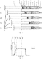
- Fig. 1 shows a pre-filled double chamber syringe 1 as a first embodiment of a multi chamber syringe unit not covered by the claims.
- the syringe1 has a longitudinal hollow glass body 2 with a tubular side wall 21 surrounding an interior of the body 2. At its one end in a longitudinal direction, in Fig. 1 this is the right end, the body 2 has a distal end side 23 which is equipped with a distal opening passing over in a needle connector 5. At its other opposite end in the longitudinal direction, in Fig. 1 this is the left end, the body 2 has a proximal end side 22 having a main opening.
- a middle plunger 3 as a separation element and an end plunger 4 as a closing element are arranged.
- a distal chamber 24 is formed in the interior of the body 2.
- a proximal chamber 25 is formed in the interior of the body 2.
- a first pharmaceutical liquid 7 in Fig. 1 and Fig. 2 also referred to as A
- a second pharmaceutical liquid 8 in the proximal chamber 25 of the body 2 .
- the syringe 1 is further equipped with an activating rod 6 which extends through the main opening at the proximal end 22 into the interior of the body 2.
- the activating rod 6 at its left end side has a finger rest and at its right end side is connected to the end plunger 4.
- the syringe 1 is operated by pushing the activating rod 6 from left to right into the interior of the body 2.
- the operation is initiated by applying a force to the finger rest of the rod 6 which, e.g. can be done by a thumb of a hand.
- the pressure inside the proximal chamber 25 is increased by the force acting on the rod 6 and the middle plunger 3 is moved from left to right into the direction of the distal end side 23 of the body 2 until it lies adjacent to or at the bulge 26. In this position a bypass channel is formed besides the middle plunger 3 by the bulge 26.
- the second pharmaceutical liquid 8 bypasses the middle plunger 3 and is transferred from the proximal chamber 25 into the distal chamber 24 wherein the middle plunger 3 is not moving.
- the first pharmaceutical liquid 8 is mixed with the second pharmaceutical liquid 7.
- the middle plunger 3 moves further to the right hand side and pushes the mixture of first and second pharmaceutical liquids 7, 8 through the needle connector 5 out of the syringe 1.
- a needle mounted to the needle connector 5 penetrates a target tissue, e.g. subcutaneously, and the syringe is activated, e.g. by the patient, as described above.
- the first and second pharmaceutical liquids 7, 8 are to a major extent injected concomitantly.
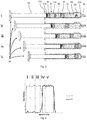
- a pre-filled double chamber syringe 10 is shown as a second embodiment of a multi chamber syringe unit according to the invention.
- the syringe 10 has a longitudinal hollow glass body 20 with a tubular side wall 210 surrounding an interior of the body 20.
- the body 20 At its one end in a longitudinal direction, in Fig. 3 this is the right end, the body 20 has a distal end side 230 which is equipped with a distal opening passing over in a needle connector 50.
- the body 20 has a proximal end side 220 having a main opening.
- the body 210 Adjacent to the distal end side 230 the body 210 has a longitudinal bulge 260 as a bypass arrangement.
- a middle plunger 30 as a separation element and an end plunger 40 as a closing element are arranged.
- a distal chamber 240 is formed in the interior of the body 20.
- a proximal chamber 250 is formed in the interior of the body 20.
- a first pharmaceutical liquid 70 in Fig. 3 and Fig. 4 also referred to as A
- a second pharmaceutical liquid 80 in the proximal chamber 250 of the body 20 arranged.
- the syringe 10 is further equipped with an activating rod 60 which extends through the main opening at the proximal end 220 into the interior of the body 20.
- the activating rod 60 at its left end side has a finger rest and at its right end side is connected to the end plunger 40.
- the syringe 10 is operated by pushing the activating rod 60 from left to right into the interior of the body 20.
- the operation is initiated by applying a force to the finger rest of the rod 60 which, e.g. can be done by a thumb of a hand.
- a pressure inside the proximal chamber 250 is increased and the middle plunger 30 is moved from left to right into the direction of the distal end side 230 of the body 20.
- the first pharmaceutical liquid 70 is provided through the needle connector 50 out of the distal chamber 240.
- the middle plunger 30 is further advanced to the right hand side and further first pharmaceutical substance 70 is dispensed.
- the middle plunger 30 is moved as far to the right such that it lies adjacent to or at the bulge 260. In this position, a bypass channel is formed besides the middle plunger 30 by the bulge 260.
- the first pharmaceutical liquid 70 originally arranged in the distal chamber 240 of the body 20 is, to a large extent, already pushed out of the syringe 10 via the needle connector 50.
- the second pharmaceutical substance 80 starts to pass the middle plunger 30 via the bypass channel.
- the second pharmaceutical liquid 80 By further advancing the activating rod 60, as shown in situation v the second pharmaceutical liquid 80 more and more bypasses the middle plunger 30 and is transferred from the proximal chamber 250 via the distal chamber 240 through the needle connector 50 out of the interior of the body 20.
- a needle mounted to the needle connector 50 penetrates a target tissue, e.g. subcutaneously, and the syringe 10 is activated, e.g. by the patient, as described above.
- the first and second pharmaceutical liquids 70, 80 are injected sequentially.
- the bulge 260 is located close or adjacent to the distal end side 230 of the body 20 the distal chamber 240 is essentially emptied before the second pharmaceutical liquid 80 bypasses the middle plunger 30. Only in situation iv there is, for a comparably short time, a mixture of the first and second pharmaceutical liquids 70, 80 provided. However, it can efficiently be achieved that the first and second pharmaceutical liquids 70, 80 are administered one after the other.
- Fig. 5 shows a first embodiment of a method of preparing a staked-in needle pre-filled double chamber syringe 19 as a multi chamber syringe (preparation method).
- the syringe 19 has a longitudinal glass body 29 with a side wall 219 surrounding an interior.
- the body 29 has a lower distal end side 239, an upper proximal end side 229 opposite to the distal end side 239 and a distal opening arranged in the distal end side 239 for providing liquids out of the syringe 19.
- the distal opening is equipped with a needle 59.
- a longitudinal bulge 269 is formed in the side wall 219 of the body 29.
- the preparation method comprises five steps A through E.
- step A the syringe 19 is positioned distal or front side down and prepared by sterilization.
- step B a first pharmaceutical liquid 79 is filled into the interior of the body 219 via the main opening at the proximal end side 229. It is located adjacent to the distal end side 239 of the body 219.
- step C a middle plunger 39 as separation element is forced into the interior of the body 219 and forwarded until it is located above the bulge 269. Thereby, a distal chamber 249 containing the first pharmaceutical liquid is formed in the interior of the body 219.
- step D a second pharmaceutical liquid 89 is filled in the interior of the body 219 via the main opening at the proximal end side 229.
- the second pharmaceutical liquid 89 lies on top of the middle plunger 39.
- step E an end plunger 49 as closing element is placed into the interior of the body 219 via its main opening at the proximal end side 229. Thereby, a closed proximal chamber 259 containing the second pharmaceutical liquid 89 is formed in the interior of the body 219.
- a second embodiment of a method of preparing a pre-filled double chamber syringe 18 as a multi chamber syringe is shown.
- the syringe 18 has a longitudinal glass body 28 with a side wall 218 surrounding an interior.
- the body 28 has a lower distal end side 238, an upper proximal end side 228 opposite to the distal end side 238 and a distal opening arranged in the distal end side 238 for providing liquids out of the body 28.
- the distal opening is equipped with a needle connector 58.
- a longitudinal bulge 268 is formed in the side wall 218 of the body 28.
- the preparation method comprises seven steps A through G.
- step A the syringe 18 is positioned distal or front side up and prepared by sterilization.
- step B a middle plunger 38 as separation element is forced bottom-up into the interior of the body 218 and forwarded until it is located below the bulge 268. Thereby, a distal chamber 248 is formed in the interior of the body 218 and above the middle plunger 38.
- step C a first pharmaceutical liquid 78 is filled top-down into the interior of the body 218 via the distal opening of the distal end side 238. It is located inside the distal chamber 248 of the body 28.
- step D a sealing cap 68 is mounted to the distal end side 238 of the body such that the distal opening is closed.
- step E the syringe 18 is turned around such that the distal side 238 of the body 28 is down and the proximal end side 228 is up.
- step F a second pharmaceutical liquid 88 is filled in the interior of the body 218 via the main opening at the proximal end side 228 of the body 28.
- the second pharmaceutical liquid 88 lies on top of the middle plunger 38.
- step G an end plunger 48 as closing element is placed into the interior of the body 218 via its main opening at the proximal end side 228. Thereby, a closed proximal chamber 258 containing the second pharmaceutical liquid 88 is formed in the interior of the body 218.
- the disclosure also covers all further features shown in the Figs. individually although they may not have been described in the afore or following description. Also, single alternatives of the embodiments described in the figures and the description and single alternatives of features thereof can be disclaimed from the subject matter of the invention or from disclosed subject matter.
- the disclosure comprises subject matter consisting of the features defined in the claims or the exemplary embodiments as well as subject matter comprising said features.
Description
- The present invention relates to a multi chamber syringe unit according to the preamble of
independent claim 1 and more particularly to a method of preparing an according multi chamber syringe unit and a therapeutic method using such a multi chamber syringe unit. - Multi chamber syringe units can comprise a longitudinal body, a separating element and a bypass arrangement. Thereby, the body has a side wall, a distal end side, a proximal end side opposite to the distal end side, an interior limited by the side wall between the distal end side and the proximal end side and a distal opening arranged in the distal end side for providing a liquid out of the body. The separating element is arranged in the interior of the body such that a distal chamber and a proximal chamber are formed in the interior of the body, wherein the separating element seals the distal chamber from the proximal chamber. The bypass arrangement is provided in the side wall of the distal chamber of the body. Such multi chamber syringe units can be used for providing and applying one or plural pharmaceutical substances or mixtures to a patient.
- Many pharmaceutical products are applied to patients in liquid form wherein injecting the product often is necessary when administration needs to be very quick, e.g. in case of an emergency, or the bioavailability via the gastro intestinal tract or other routes of administration is not sufficiently given. Particularly for subcutaneous, intramuscular, intradermal, intravitreal or other injections, the pharmaceutical substances are often provided in pre-filled syringes wherein staked-in needle prefilled syringes but also other syringes and cartridges or injectors have been shown to be comparably convenient to handle and use. In pre-filled syringes the pharmaceutical substance is provided in the interior of the syringe in a liquid form ready for being applied. Like this, the user receives a ready-to-inject syringe without the requirement to fill the pharmaceutical solution into the syringe or sometimes even without the need to manually assemble the needle to the syringe body. The occurrence of injuries or inappropriate handling during application can thereby be substantially lowered.
- For pharmaceutical substances being unstable in liquid form such as many biopharmaceutical substances it is also known to provide the pharmaceutical substance in a freeze-dried or lyophilized form in which it is essentially more stable and robust compared to its liquid form. For delivering and applying such pharmaceutical substances specific double chamber syringes are used wherein one chamber houses the lyophilized pharmaceutical substance and the other a suitable diluent. Before being injected the lyophilized pharmaceutical substance is then reconstituted or solved in a diluent or liquid. Such reconstitution of the pharmaceutical substance inside the double chamber syringe is performed by transferring the diluent into the chamber of the lyophilized pharmaceutical substance and mixing the two. In liquid form, the pharmaceutical substance is then injected and delivered to the patient.
- However, in many medical therapies it is required to apply a plurality of pharmaceutical substances. Thereby, it often is required to inject two or more substances which for stability reasons can only be mixed together shortly before administration. In these cases the use of pre-filled syringes often is not possible. Typically, the pharmaceutical substances are mixed before administration, provided into a syringe and then injected. Since such mixing and provision into the syringe has to be very accurate in order to assure adequate mixing ratio and a contamination free administration it is typically required that a skilled person such as a pharmacist prepares such a dosage form and a skilled person such as a doctor or a nurse performs administration.
- Furthermore, in therapies requiring application of plural pharmaceutical substance it is also often required to sequentially inject two or more substances. For example, in some applications it is desired in a first step to inject an anaesthetic and in a second step to inject a therapeutic ingredient. In such applications, two injections have to be performed which, particularly when being performed by untrained persons such as the patients themselves, doubles the risk of a misapplication. For example, the risk of an infection due to contamination is considerably higher if plural injections have to be performed. In this context,
WO 2008/007370 A2 describes a double chamber syringe for sequentially sequentially administering two liquids by one single injection.US 2012/0100103 A1 describes an in situ forming injectable hydrogel andWO 2014/203133 A1 describes a hyaluronidase from S. koganeiensis. - Therefore, there is need for a device or method allowing for adequately administering plural pharmaceutical substances by injection.
- According to the invention this need is fulfilled by a syringe as it is defined by the features of
independent claim 1. Preferred embodiments are subject of the dependent claims. - In particular, the invention is a multi chamber syringe unit comprising a longitudinal body with a side wall, a distal end side, a proximal end side opposite to the distal end side, an interior limited by the side wall between the distal end side and the proximal end side and a distal opening arranged in the distal end side for providing a liquid out of the body. The multi chamber syringe unit further has a separating element arranged in the interior of the body such that a distal chamber and a proximal chamber are formed in the interior of the body, wherein the separating element seals the distal chamber from the proximal chamber. The separating element can be a plunger or a middle plunger or any other temporary separation element. They can be made of an elastic material such as rubber or an elastic plastic material such as butyl.
- The multi chamber syringe unit is equipped with a bypass arrangement being provided in the side wall of the distal chamber of the body. It can, e.g., be embodied by a bulge in the side wall which is dimensioned to allow liquid to pass the separation element when the being positioned adjacent to the bulge. Or, alternatively, it can be embodied by a similarly dimensioned groove or channel in the side wall. Also, other arrangements that allows liquid to bypass or flow through the separation element separating the plurality of chambers are possible.
- The multi chamber syringe unit particularly comprises a first pharmaceutical liquid arranged in the distal chamber of the body and a second pharmaceutical liquid arranged in the proximal chamber of the body.
- The multi chamber syringe unit can be a double chamber syringe or double chamber syringe unit. For many advantageous applications it can be a staked-in needle pre-filled double chamber syringe.
- In an embodiment not covered by the claims, the multi chamber syringe unit is adapted for mixing the first pharmaceutical liquid with the second pharmaceutical liquid before injection. In particular, such embodiments allow injecting the two pharmaceutical liquids concomitantly.
- For allowing such concomitant injection, the bypass arrangement can be located and shaped such that when the multi chamber syringe unit is activated, typically by pushing an activation rod, the second pharmaceutical liquid is transferred from the second chamber into the first chamber. For example, pushing the activation rod may cause an increase of pressure inside the second chamber such that the separating element is moved towards the distal end of the body. When it is located at the bypass arrangement, the second pharmaceutical liquid passes into the distal chamber. There it is mixed with the first pharmaceutical liquid. By further advancing the activation rod, the mixed first and second pharmaceutical liquids are pushed out of the distal opening of the body typically into a needle connected to the distal opening.
- Alternatively, the multi chamber syringe unit can be arranged for sequentially providing the first and second pharmaceutical liquids. For this purpose, the multi chamber syringe unit is adapted for, upon activation, initially providing the first pharmaceutical liquid out of the distal opening of the body and afterwards providing the second pharmaceutical liquid out of the distal opening of the body.
- According to the invention, for this, the bypass arrangement is located adjacent to the distal end side of the body. In this connection the term "adjacent" can be referred to as close to the distal end side as possible or feasible. The closer the bypass arrangement is located at the distal end side the less first pharmaceutical liquid is left in the interior of the body when the second pharmaceutical liquid passes via the bypass arrangement. Thereby, the body and the separating element preferably are arranged such that the distal chamber is essentially emptied when the separating element is moved to or located at the bypass arrangement.
- In use of these embodiments allowing for a sequential provision of the first and second pharmaceutical liquids, an activation rod may be pushed into the interior of the body which causes an increase of the pressure inside the proximal chamber. This causes the separating element to be moved towards the distal end side. Thereby, the first pharmaceutical liquid is forced out of the distal opening of the body. When the separating element is located at the bypass arrangement, the distal chamber is essentially empty. In this connection the term "essentially empty" can still allow some residues of the first pharmaceutical liquid. In particular, the space between the separating element and the distal end side may still contain some few first pharmaceutical substance left when the separating element is at the bypass arrangement. By further advancing the activation rod the second liquid passes the separating element and is provided out of the distal opening of the body.
- Thus, as the need may be, the multi chamber syringe allows for conveniently and safely providing a first and a second pharmaceutical liquid out of the body. In particular, the first and the second pharmaceutical liquid can be injected in a predefined and preferred manner, i.e. sequentially. Like this, the multi chamber syringe unit allows for adequately administering plural pharmaceutical liquids by injection.
- In a first preferred embodiment, the first pharmaceutical liquid is an anaesthetic and the second pharmaceutical liquid comprises a therapeutic active ingredient. Thereby, the anaesthetic preferably is an amid based anaesthetic. Providing the anaesthetic as a first pharmaceutical liquid allows for a comparably comfortable administration of the therapeutic active ingredient which alone might be painful. In such configurations it might in many applications be particularly beneficial if the multi chamber syringe unit is embodied to sequentially provide the first and second pharmaceutical liquids. In particular, it might be beneficial if the multi chamber syringe unit is adapted to provide the anaesthetic in a first step and the therapeutic active ingredient in a second step.
- In a second preferred embodiment, the first pharmaceutical liquid comprises a first therapeutic active ingredient and the second pharmaceutical liquid comprises a second therapeutic active ingredient. This can be useful for combinations of active ingredients which are used in one single therapy. In applications not covered by the claims it might also be useful to mix the two active ingredients and then injecting the mixture to a patient. Such administration might be particularly beneficial when the mixture of the two active ingredients is not stable for a certain time or when the two active ingredients do react with each other.
- According to the invention, the first pharmaceutical liquid comprises an enzyme and the second pharmaceutical liquid comprises a therapeutic active ingredient. Thereby, the enzyme is a hyaluronidase. Often, the acceptance of the tissue where the therapeutic active ingredient is provided within a particular therapy is comparably low or insufficient especially for comparably large injection volumes. Thus, the tissue can only accept a certain amount of active ingredient whereas it would be advantageous for the success of the therapy to provide more active ingredient. In such situations it has been shown that in some cases the acceptance of the tissue can be increased when the tissue first receives an enzyme. For example, in such cases it can be beneficial to sequentially inject the enzyme and afterwards the therapeutic active ingredient. With the third embodiment of the invention this can be achieved in a safe, efficient and convenient manner.
- The therapeutic active ingredients described herein can be small molecules. However, the therapeutic active ingredient preferably comprises a protein wherein the protein can be an antibody such as a monoclonal antibody. When using such a protein as therapeutic active ingredient the above mentioned effects can be particularly advantageous.
- The first pharmaceutical liquid and the second pharmaceutical liquid together from a gel such as a hydrogel or complex upon mixing. A (hydro)gel or complex can be beneficial in therapy since it allows for continuously dispersing the therapeutic active ingredient over a comparably long time in a controlled release. Thus, by being a (hydro)gel or complex after mixing this embodiment of the multi chamber syringe unit allows for efficiently provide the active ingredient over a comparably long time at the place of injection.
- In addition to the separation element, the multi chamber syringe unit may comprise a closing element arranged in the interior of the body closing the proximal chamber. The closing element can be a plunger such as an end plunger. Such a closing element allows for efficiently sealing the proximal chamber and preventing contamination.
- Preferably, the multi chamber syringe unit comprises a needle connected to the distal opening of the distal end side of the body. Such a needle allows for efficiently injecting the first and second pharmaceutical liquids to the patient. Also, the multi chamber syringe unit can comprise an activation rod extending through the proximal end side of the body into the interior of the body. Such activation rod allows for conveniently activating and applying the multi chamber syringe unit.
- In another embodiment not covered by the claims, a method of preparing a multi chamber syringe (preparation method) is provided. The multi chamber syringe has a longitudinal body with a side wall, a distal end side, a proximal end side opposite to the distal end side, an interior limited by the side wall between the distal end side and the proximal end side and a distal opening arranged in the distal end side for providing a liquid out of the multi chamber syringe. The preparation method comprises the steps of: sterilizing the multi chamber syringe; filling a first pharmaceutical liquid into the interior of the body adjacent to its distal end side; providing a middle plunger in the interior of the body of the multi chamber syringe such that a distal chamber and a proximal chamber are formed in the interior of the body; and filling a second pharmaceutical liquid into the proximal chamber of the interior of the body.
- The various steps of the preparation method can be performed in the sequence as listed or in any other suitable sequence. For example, the step of providing a middle plunger in the interior of the body can be performed before filling any liquid. Thereby, the first pharmaceutical liquid can be filled from the distal end side and the second pharmaceutical liquid from the proximal end side after the middle plunger is arranged in the interior of the body.
- Further, the various steps of the preparation method can all be performed at a single location or site. They can also be distributed to different locations which allows for a particularly efficient performance of single steps or combinations thereof. For example, the step of sterilizing the multi chamber syringe can be performed at the location where the syringe is filled. Or, it can be performed at the site of the manufacturer of the syringe such that the syringe is delivered in a pre-sterilized manner, e.g. as a so-called ready-to-fill syringe.
- The preparation method according to the invention allows for efficiently providing a multi chamber syringe which can be used as a multi chamber syringe unit as described above. Like this, also the effects and benefits described above in connection with the multi chamber syringe unit according to the invention and the preferred embodiments thereof can efficiently be achieved.
- Preferably, within the preparation method the first pharmaceutical liquid comprises any one of the group consisting of an anaesthetic, a first therapeutic active ingredient, a first hydrogel component and an enzyme such as hyaluronidase, and the second pharmaceutical liquid comprises a second hydrogel component and/or a second therapeutic active ingredient. The first pharmaceutical liquid can also comprise any combination of the components of the group.
- Preferably, the preparation method further comprises the step of: providing a closing element such as an end plunger in the interior of the body of the multi chamber syringe such that the proximal chamber is closed.
- Preferably, within the preparation method the multi chamber syringe is aligned with the distal end side of the body down during all steps of the method. Such an alignment allows for a particular efficient performing of the preparation method.
- In another embodiment not covered by the claims, a therapeutic method is provided, comprising the steps of: obtaining a multi chamber syringe unit as described above and provided with a needle connected to the distal opening of the distal end side of the body; subcutaneously penetrating the needle of the multi chamber syringe unit; and activating the multi chamber syringe unit.
- The term "activating" as used in this connection can relate to starting operation or operating the multi chamber syringe unit. It can particularly relate to providing the pharmaceutical liquids out of the body. In embodiments having a rod, such activation can be performed by pressing the rod into the interior of the body.
- As described above with respect to plural aspects of the multi chamber syringe unit such therapy can be beneficial for plural reasons. In particular, by using the multi chamber syringe unit within the therapeutic method various effects and benefits described above in connection with the multi chamber syringe unit according to the invention and the preferred embodiments thereof can be achieved.
- In one preferred embodiment of the therapeutic method, the first pharmaceutical liquid and the second pharmaceutical liquid of the multi chamber syringe unit are administered sequentially. In another preferred embodiment of the therapeutic method the first pharmaceutical liquid and the second pharmaceutical liquid of the multi chamber unit are administered concomitantly.
- A first particular example of a therapeutic method comprises the steps of: obtaining a multi chamber syringe unit as described above provided with a needle connected to the distal opening of the distal end side of the body; subcutaneously penetrating the needle of the multi chamber syringe unit; and activating the multi chamber syringe unit.
- A second particular example of a therapeutic method is the first particular example, wherein the first pharmaceutical liquid and the second pharmaceutical liquid of the multi chamber syringe unit are administered sequentially.
- A third particular example of a therapeutic method is the first particular example, wherein the first pharmaceutical liquid and the second pharmaceutical liquid of the multi chamber syringe unit are administered concomitantly.
- The aspects of the invention mentioned hereinbefore and other aspects will be apparent from and elucidated with reference to the embodiments described hereinafter.
- The multi chamber syringe unit according to the invention, the preparation method and the therapeutic method are described in more detail herein below by way of exemplary embodiments and with reference to the attached drawings, in which:
- Fig. 1
- shows a side view on a first embodiment of a double chamber syringe as a first embodiment of a multi chamber syringe unit during concomitant liquid provision in a first embodiment of a therapeutic method;
- Fig. 2
- shows a graph of the liquid provision of the therapeutic method of
Fig. 1 ; - Fig. 3
- shows a side view on a second embodiment of a double chamber syringe as a second embodiment of a multi chamber syringe unit according to the invention during sequential liquid provision in a second embodiment of a therapeutic method not covered by the claims;
- Fig. 4
- shows a graph of the liquid provision of the therapeutic method of
Fig. 3 ; - Fig. 5
- shows a side view on a third embodiment of a double chamber syringe as a third embodiment of a multi chamber syringe unit during preparation in a first embodiment of a preparation method; and
- Fig. 6
- shows a side view on a fourth embodiment of a double chamber syringe as a fourth embodiment of a multi chamber syringe unit during preparation in a second embodiment of a preparation method.
- In the following description certain terms are used for reasons of convenience and are not intended to limit the invention. The terms "right", "left", "up", "down", "under" and "above" refer to directions in the figures. The terminology comprises the explicitly mentioned terms as well as their derivations and terms with a similar meaning. Also, spatially relative terms, such as "beneath", "below", "lower", "above", "upper", "proximal", "distal", and the like, may be used to describe one element's or feature's relationship to another element or feature as illustrated in the figures. These spatially relative terms are intended to encompass different positions and orientations of the devices in use or operation in addition to the position and orientation shown in the figures. For example, if a device in the figures is turned over, elements described as "below" or "beneath" other elements or features would then be "above" or "over" the other elements or features. Thus, the exemplary term "below" can encompass both positions and orientations of above and below. The devices may be otherwise oriented (rotated 90 degrees or at other orientations), and the spatially relative descriptors used herein interpreted accordingly. Likewise, descriptions of movement along and around various axes include various special device positions and orientations.
- To avoid repetition in the figures and the descriptions of the various aspects and illustrative embodiments, it should be understood that many features are common to many aspects and embodiments. Omission of an aspect from a description or figure does not imply that the aspect is missing from embodiments that incorporate that aspect. Instead, the aspect may have been omitted for clarity and to avoid prolix description. In this context, the following applies to the rest of this description: If, in order to clarify the drawings, a figure contains reference signs which are not explained in the directly associated part of the description, then it is referred to previous or following description sections. Further, for reason of lucidity, if in a drawing not all features of a part are provided with reference signs it is referred to other drawings showing the same part. Like numbers in two or more figures represent the same or similar elements.
-
Fig. 1 shows a pre-filleddouble chamber syringe 1 as a first embodiment of a multi chamber syringe unit not covered by the claims. The syringe1 has a longitudinalhollow glass body 2 with atubular side wall 21 surrounding an interior of thebody 2. At its one end in a longitudinal direction, inFig. 1 this is the right end, thebody 2 has adistal end side 23 which is equipped with a distal opening passing over in aneedle connector 5. At its other opposite end in the longitudinal direction, inFig. 1 this is the left end, thebody 2 has aproximal end side 22 having a main opening. - Between the
distal end side 23 and theproximal end side 22 theside wall 21 is equipped with alongitudinal bulge 26 as a bypass arrangement. In the interior of the body 2 amiddle plunger 3 as a separation element and anend plunger 4 as a closing element are arranged. Between themiddle plunger 3 and the distal end side 23 adistal chamber 24 is formed in the interior of thebody 2. Similarly, between themiddle plunger 3 and the end plunger 4 aproximal chamber 25 is formed in the interior of thebody 2. In thedistal chamber 24 of the body 2 a first pharmaceutical liquid 7 (inFig. 1 and Fig. 2 also referred to as A) and in theproximal chamber 25 of the body 2 a second pharmaceutical liquid 8 (inFig. 1 and Fig. 2 also referred to as B) are arranged. - The
syringe 1 is further equipped with an activatingrod 6 which extends through the main opening at theproximal end 22 into the interior of thebody 2. The activatingrod 6 at its left end side has a finger rest and at its right end side is connected to theend plunger 4. - As visualized in
Fig. 1 thesyringe 1 is operated by pushing the activatingrod 6 from left to right into the interior of thebody 2. Thereby, in situation i the operation is initiated by applying a force to the finger rest of therod 6 which, e.g. can be done by a thumb of a hand. As shown in situation ii the pressure inside theproximal chamber 25 is increased by the force acting on therod 6 and themiddle plunger 3 is moved from left to right into the direction of thedistal end side 23 of thebody 2 until it lies adjacent to or at thebulge 26. In this position a bypass channel is formed besides themiddle plunger 3 by thebulge 26. By further advancing the activatingrod 6 as shown in situation iii, the secondpharmaceutical liquid 8 bypasses themiddle plunger 3 and is transferred from theproximal chamber 25 into thedistal chamber 24 wherein themiddle plunger 3 is not moving. There, as shown in situation iv, the firstpharmaceutical liquid 8 is mixed with the secondpharmaceutical liquid 7. By still further advancing the activatingrod 6, as shown in situation v, themiddle plunger 3 moves further to the right hand side and pushes the mixture of first and secondpharmaceutical liquids needle connector 5 out of thesyringe 1. - In use in a therapeutic application a needle mounted to the
needle connector 5 penetrates a target tissue, e.g. subcutaneously, and the syringe is activated, e.g. by the patient, as described above. Thereby, as can be seen inFig. 2 , even though in situation i some first pharmaceutical liquid is purely provided the first and secondpharmaceutical liquids - In
Fig. 3 a pre-filleddouble chamber syringe 10 is shown as a second embodiment of a multi chamber syringe unit according to the invention. Thesyringe 10 has a longitudinalhollow glass body 20 with atubular side wall 210 surrounding an interior of thebody 20. At its one end in a longitudinal direction, inFig. 3 this is the right end, thebody 20 has adistal end side 230 which is equipped with a distal opening passing over in aneedle connector 50. At its other opposite end in the longitudinal direction, inFig. 3 this is the left end, thebody 20 has aproximal end side 220 having a main opening. - Adjacent to the
distal end side 230 thebody 210 has alongitudinal bulge 260 as a bypass arrangement. In the interior of the body 20 amiddle plunger 30 as a separation element and anend plunger 40 as a closing element are arranged. Between themiddle plunger 30 and the distal end side 230 adistal chamber 240 is formed in the interior of thebody 20. Similarly, between themiddle plunger 30 and the end plunger 40 aproximal chamber 250 is formed in the interior of thebody 20. In thedistal chamber 240 of the body 20 a first pharmaceutical liquid 70 (inFig. 3 and Fig. 4 also referred to as A) is arranged. In theproximal chamber 250 of the body 20 a second pharmaceutical liquid 80 (inFig. 3 and Fig. 4 also referred to as B) is arranged. - The
syringe 10 is further equipped with an activatingrod 60 which extends through the main opening at theproximal end 220 into the interior of thebody 20. The activatingrod 60 at its left end side has a finger rest and at its right end side is connected to theend plunger 40. - As visualized in
Fig. 3 thesyringe 10 is operated by pushing the activatingrod 60 from left to right into the interior of thebody 20. Thereby, in situation i the operation is initiated by applying a force to the finger rest of therod 60 which, e.g. can be done by a thumb of a hand. As shown in situation ii a pressure inside theproximal chamber 250 is increased and themiddle plunger 30 is moved from left to right into the direction of thedistal end side 230 of thebody 20. During this movement of themiddle plunger 30 the firstpharmaceutical liquid 70 is provided through theneedle connector 50 out of thedistal chamber 240. As shown in situation iii themiddle plunger 30 is further advanced to the right hand side and further firstpharmaceutical substance 70 is dispensed. In situation iv themiddle plunger 30 is moved as far to the right such that it lies adjacent to or at thebulge 260. In this position, a bypass channel is formed besides themiddle plunger 30 by thebulge 260. The firstpharmaceutical liquid 70 originally arranged in thedistal chamber 240 of thebody 20 is, to a large extent, already pushed out of thesyringe 10 via theneedle connector 50. The secondpharmaceutical substance 80 starts to pass themiddle plunger 30 via the bypass channel. By further advancing the activatingrod 60, as shown in situation v the secondpharmaceutical liquid 80 more and more bypasses themiddle plunger 30 and is transferred from theproximal chamber 250 via thedistal chamber 240 through theneedle connector 50 out of the interior of thebody 20. - In use, in a therapeutic application a needle mounted to the
needle connector 50 penetrates a target tissue, e.g. subcutaneously, and thesyringe 10 is activated, e.g. by the patient, as described above. Thereby, as shown inFig. 4 , the first and secondpharmaceutical liquids bulge 260 is located close or adjacent to thedistal end side 230 of thebody 20 thedistal chamber 240 is essentially emptied before the secondpharmaceutical liquid 80 bypasses themiddle plunger 30. Only in situation iv there is, for a comparably short time, a mixture of the first and secondpharmaceutical liquids pharmaceutical liquids -
Fig. 5 shows a first embodiment of a method of preparing a staked-in needle pre-filleddouble chamber syringe 19 as a multi chamber syringe (preparation method). Thesyringe 19 has a longitudinal glass body 29 with aside wall 219 surrounding an interior. The body 29 has a lowerdistal end side 239, an upperproximal end side 229 opposite to thedistal end side 239 and a distal opening arranged in thedistal end side 239 for providing liquids out of thesyringe 19. The distal opening is equipped with aneedle 59. Between thedistal end side 239 and the proximal end side 229 alongitudinal bulge 269 is formed in theside wall 219 of the body 29. - As shown in
Fig. 5 , the preparation method comprises five steps A through E. In step A thesyringe 19 is positioned distal or front side down and prepared by sterilization. In step B a firstpharmaceutical liquid 79 is filled into the interior of thebody 219 via the main opening at theproximal end side 229. It is located adjacent to thedistal end side 239 of thebody 219. In step C amiddle plunger 39 as separation element is forced into the interior of thebody 219 and forwarded until it is located above thebulge 269. Thereby, adistal chamber 249 containing the first pharmaceutical liquid is formed in the interior of thebody 219. - In step D a second
pharmaceutical liquid 89 is filled in the interior of thebody 219 via the main opening at theproximal end side 229. The secondpharmaceutical liquid 89 lies on top of themiddle plunger 39. In step E anend plunger 49 as closing element is placed into the interior of thebody 219 via its main opening at theproximal end side 229. Thereby, a closedproximal chamber 259 containing the secondpharmaceutical liquid 89 is formed in the interior of thebody 219. - In
Fig. 6 a second embodiment of a method of preparing a pre-filleddouble chamber syringe 18 as a multi chamber syringe (preparation method) is shown. Thesyringe 18 has a longitudinal glass body 28 with aside wall 218 surrounding an interior. The body 28 has a lowerdistal end side 238, an upperproximal end side 228 opposite to thedistal end side 238 and a distal opening arranged in thedistal end side 238 for providing liquids out of the body 28. The distal opening is equipped with aneedle connector 58. Between thedistal end side 238 and the proximal end side 228 alongitudinal bulge 268 is formed in theside wall 218 of the body 28. - As shown in
Fig. 6 , the preparation method comprises seven steps A through G. In step A thesyringe 18 is positioned distal or front side up and prepared by sterilization. In step B amiddle plunger 38 as separation element is forced bottom-up into the interior of thebody 218 and forwarded until it is located below thebulge 268. Thereby, adistal chamber 248 is formed in the interior of thebody 218 and above themiddle plunger 38. In step C a firstpharmaceutical liquid 78 is filled top-down into the interior of thebody 218 via the distal opening of thedistal end side 238. It is located inside thedistal chamber 248 of the body 28. In step D a sealingcap 68 is mounted to thedistal end side 238 of the body such that the distal opening is closed. - In step E the
syringe 18 is turned around such that thedistal side 238 of the body 28 is down and theproximal end side 228 is up. In step F a secondpharmaceutical liquid 88 is filled in the interior of thebody 218 via the main opening at theproximal end side 228 of the body 28. The secondpharmaceutical liquid 88 lies on top of themiddle plunger 38. In step G anend plunger 48 as closing element is placed into the interior of thebody 218 via its main opening at theproximal end side 228. Thereby, a closedproximal chamber 258 containing the secondpharmaceutical liquid 88 is formed in the interior of thebody 218. - This description and the accompanying drawings that illustrate aspects and embodiments of the present invention should not be taken as limiting-the claims defining the protected invention. In other words, while the invention has been illustrated and described in detail in the drawings and foregoing description, such illustration and description are to be considered illustrative or exemplary and not restrictive. Various mechanical, compositional, structural, electrical, and operational changes may be made without departing from the scope of the claims. In some instances, well-known circuits, structures and techniques have not been shown in detail in order not to obscure the invention. Thus, it will be understood that changes and modifications may be made by those of ordinary skill within the scope of the following claims.
- The disclosure also covers all further features shown in the Figs. individually although they may not have been described in the afore or following description. Also, single alternatives of the embodiments described in the figures and the description and single alternatives of features thereof can be disclaimed from the subject matter of the invention or from disclosed subject matter. The disclosure comprises subject matter consisting of the features defined in the claims or the exemplary embodiments as well as subject matter comprising said features.
- Furthermore, in the claims the word "comprising" does not exclude other elements or steps, and the indefinite article "a" or "an" does not exclude a plurality. A single unit or step may fulfil the functions of several features recited in the claims. The mere fact that certain measures are recited in mutually different dependent claims does not indicate that a combination of these measures cannot be used to advantage. The terms "essentially", "about", "approximately" and the like in connection with an attribute or a value particularly also define exactly the attribute or exactly the value, respectively. The term "about" in the context of a given numerate value or range refers to a value or range that is, e.g., within 20%, within 10%, within 5%, or within 2% of the given value or range. Components described as coupled or connected may be electrically or mechanically directly coupled, or they may be indirectly coupled via one or more intermediate components. Any reference signs in the claims should not be construed as limiting the scope.
Claims (3)
- Multi chamber syringe unit (1; 10; 18; 19) comprising
a longitudinal body (2; 20; 28; 29) with a side wall (21; 210; 218; 219), a distal end side (23; 230; 238; 239), a proximal end side (22; 220; 228; 229) opposite to the distal end side (23; 230; 238; 239), an interior limited by the side wall (21; 210; 218; 219) between the distal end side (23; 230; 238; 239) and the proximal end side (22; 220; 228; 229) and a distal opening arranged in the distal end side (23; 230; 238; 239) for providing a liquid out of the body (2; 20; 28; 29);
a separating element (3; 30; 38; 39) arranged in the interior of the body (2; 20; 28; 29) such that a distal chamber (24; 240; 248; 249) and a proximal chamber (25; 250; 258; 259) are formed in the interior of the body (2; 20; 28; 29), wherein the separating element (3; 30; 38; 39) seals the distal chamber (24; 240; 248; 249) from the proximal chamber (25; 250; 258; 259);
a bypass arrangement (26; 260; 268; 269) provided in the side wall (21; 210; 218; 219) of the distal chamber (24; 240; 248; 249) of the body (2; 20; 28; 29);
a first pharmaceutical liquid (7; 70; 78; 79) arranged in the distal chamber (24; 240; 248; 249) of the body (2; 20; 28; 29); and
a second pharmaceutical liquid (8; 80; 88; 89) arranged in the proximal chamber (25; 250; 258; 259) of the body (2; 20; 28; 29), wherein
the bypass arrangement (26; 260; 268; 269) is located adjacent to the distal end side (23; 230; 238; 239) of the body (2; 20; 28; 29), and
the body (2; 20; 28; 29) and the separating element (3; 30; 38; 39) are arranged such that the distal chamber (24; 240; 248; 249) is essentially emptied when the separating element (3; 30; 38; 39) is moved to the bypass arrangement (26; 260; 268; 269),
characterized in that
the first pharmaceutical liquid (7; 70; 78; 79) comprises an enzyme being hyaluronidase and the second pharmaceutical liquid (8; 80; 88; 89) comprises a therapeutic active ingredient, and
the first pharmaceutical liquid (7; 70; 78; 79) and the second pharmaceutical liquid (8; 80; 88; 89) together form a gel such as a hydrogel or complex upon mixing. - Multi chamber syringe unit (1; 10; 18; 19) according to claim 1, wherein the therapeutic active ingredient comprises a protein.
- Multi chamber syringe unit (1; 10; 18; 19) according to claim 1 or 2, comprising a needle (58) connected to the distal opening of the distal end side (23; 230; 238; 239) of the body (2; 20; 28; 29).
Applications Claiming Priority (2)
| Application Number | Priority Date | Filing Date | Title |
|---|---|---|---|
| EP15188184 | 2015-10-02 | ||
| PCT/EP2016/073272 WO2017055462A1 (en) | 2015-10-02 | 2016-09-29 | Multi chamber syringe unit and method of preparing a multi chamber syringe |
Publications (2)
| Publication Number | Publication Date |
|---|---|
| EP3355968A1 EP3355968A1 (en) | 2018-08-08 |
| EP3355968B1 true EP3355968B1 (en) | 2021-05-12 |
Family
ID=54252196
Family Applications (1)
| Application Number | Title | Priority Date | Filing Date |
|---|---|---|---|
| EP16774503.3A Active EP3355968B1 (en) | 2015-10-02 | 2016-09-29 | Multi chamber syringe unit |
Country Status (6)
| Country | Link |
|---|---|
| US (2) | US20180256818A1 (en) |
| EP (1) | EP3355968B1 (en) |
| JP (1) | JP2018531065A (en) |
| CN (1) | CN108136128B (en) |
| HK (1) | HK1255970A1 (en) |
| WO (1) | WO2017055462A1 (en) |
Families Citing this family (6)
| Publication number | Priority date | Publication date | Assignee | Title |
|---|---|---|---|---|
| EP4306137A3 (en) | 2017-03-27 | 2024-04-03 | Regeneron Pharmaceuticals, Inc. | Sterilisation method |
| US11940445B2 (en) * | 2018-04-06 | 2024-03-26 | University Of Rochester | ABO blood group point-of-care testing |
| DE102019101279A1 (en) * | 2019-01-18 | 2020-07-23 | Gerresheimer Bünde Gmbh | Prefillable syringe |
| CA3130053A1 (en) * | 2019-02-22 | 2020-08-27 | Credence Medsystems, Inc. | System and method for safety syringe |
| US11899026B2 (en) | 2019-10-07 | 2024-02-13 | University of Rochester, Rochester Institute of Technology | ABO blood group point-of-care chip testing |
| CH717267A2 (en) | 2020-03-30 | 2021-09-30 | Ypsomed Ag | Auto-injector with a multi-chamber product container. |
Citations (9)
| Publication number | Priority date | Publication date | Assignee | Title |
|---|---|---|---|---|
| US20050164981A1 (en) * | 2000-05-11 | 2005-07-28 | Burdick Julie-Anne M. | Biological lubricant composition and method of applying lubricant composition |
| US20070036745A1 (en) * | 2003-12-30 | 2007-02-15 | Leshchiner Adelya K | Polymeric materials, their preparation and use |
| US20070212385A1 (en) * | 2006-03-13 | 2007-09-13 | David Nathaniel E | Fluidic Tissue Augmentation Compositions and Methods |
| JP2007260349A (en) * | 2006-03-30 | 2007-10-11 | Daikyo Seiko Ltd | Double-chamber container syringe |
| US20090092677A1 (en) * | 2007-10-05 | 2009-04-09 | Boston Scientific Scimed, Inc. | Multi-component particles for injection and processes for forming the same |
| WO2010130810A1 (en) * | 2009-05-14 | 2010-11-18 | Fidia Farmaceutici S.P.A. | Extracellular yaluronidase from streptomyces koganeiensis |
| US20120100103A1 (en) * | 2009-07-02 | 2012-04-26 | Ki-Dong Park | In situ forming hydrogel and biomedical use thereof |
| US20120156164A1 (en) * | 2009-09-04 | 2012-06-21 | Ajou University Industry-Academic Cooperation Foundation | In situ-forming hydrogel for tissue adhesives and biomedical use thereof |
| WO2014203133A1 (en) * | 2013-06-17 | 2014-12-24 | Fidia Farmaceutici S.P.A. | Bacterial hyaluronidase and process for its production |
Family Cites Families (21)
| Publication number | Priority date | Publication date | Assignee | Title |
|---|---|---|---|---|
| GB1464797A (en) * | 1973-08-02 | 1977-02-16 | American Cyanamid Co | Injectable liquid vitamin preparation |
| DE3806562A1 (en) * | 1988-03-01 | 1989-09-14 | Alpha Therapeutic Gmbh | TWO CHAMBER SYRINGE WITH A FILLING OF ACTIVITY SENSITIVE HUMAN PROTEIN AS AN ACTIVE SUBSTANCE |
| WO2006011356A1 (en) * | 2004-07-29 | 2006-02-02 | Wakayama University | Impulse-responsive measurement method and device |
| DE102005038497A1 (en) * | 2005-08-13 | 2007-02-15 | Boehringer Ingelheim Pharma Gmbh & Co. Kg | Double chamber container without bypass |
| US8197435B2 (en) * | 2006-05-02 | 2012-06-12 | Emory University | Methods and devices for drug delivery to ocular tissue using microneedle |
| WO2008007370A2 (en) * | 2006-07-11 | 2008-01-17 | Nanopass Technologies Ltd. | Dual chamber injector intergrated with micro-needles |
| JP2008259704A (en) * | 2007-04-12 | 2008-10-30 | Hisamitsu Pharmaceut Co Inc | Prefilled syringe |
| US20080275387A1 (en) * | 2007-05-03 | 2008-11-06 | Yeadon Stephen C | Hemostatic medical device |
| US8057427B2 (en) * | 2007-05-09 | 2011-11-15 | Meridian Medical Technologies, Inc. | Drug delivery system with a small amount of a therapeutic agent |
| EP2214639A2 (en) * | 2007-11-06 | 2010-08-11 | Stuart L. Weg | Anesthetic composition, formulation and method of use |
| US9205194B2 (en) * | 2011-08-05 | 2015-12-08 | Unitract Syringe Pty Ltd | Dual chamber mixing device for a syringe |
| WO2013149032A1 (en) * | 2012-03-29 | 2013-10-03 | Biogen Idec Ma Inc. | Delivery device and components thereof |
| US9522235B2 (en) * | 2012-05-22 | 2016-12-20 | Kaleo, Inc. | Devices and methods for delivering medicaments from a multi-chamber container |
| GB201210580D0 (en) * | 2012-06-14 | 2012-08-01 | 3M Innovative Properties Co | Metered dose dispensing valve |
| JP5916530B2 (en) * | 2012-06-21 | 2016-05-11 | ぺんてる株式会社 | Container / Syringe |
| US9005108B2 (en) * | 2012-09-27 | 2015-04-14 | Palo Alto Research Center Incorporated | Multiple reservoir drug delivery device and methods |
| US9764093B2 (en) * | 2012-11-30 | 2017-09-19 | Sio2 Medical Products, Inc. | Controlling the uniformity of PECVD deposition |
| US9072678B2 (en) * | 2013-03-14 | 2015-07-07 | Pathak Holdings Llc | Methods for local drug delivery by microinjection |
| EP3003428A4 (en) * | 2013-06-05 | 2017-05-31 | The Regents of the University of California | Hydrogel pressure sealant system |
| US10363375B2 (en) * | 2014-07-22 | 2019-07-30 | OROFINO PHARMACEUTICALS GROUP S.r.l. | Pre-filled injection device |
| US20160067406A1 (en) * | 2014-09-08 | 2016-03-10 | Ethicon, Inc. | Modular Apparatus for Delivery of Fluid Materials |
-
2016
- 2016-09-29 EP EP16774503.3A patent/EP3355968B1/en active Active
- 2016-09-29 WO PCT/EP2016/073272 patent/WO2017055462A1/en active Application Filing
- 2016-09-29 JP JP2018515933A patent/JP2018531065A/en not_active Ceased
- 2016-09-29 US US15/762,276 patent/US20180256818A1/en not_active Abandoned
- 2016-09-29 CN CN201680058182.5A patent/CN108136128B/en active Active
-
2018
- 2018-11-23 HK HK18115044.4A patent/HK1255970A1/en unknown
-
2022
- 2022-12-22 US US18/145,388 patent/US20230128911A1/en active Pending
Patent Citations (9)
| Publication number | Priority date | Publication date | Assignee | Title |
|---|---|---|---|---|
| US20050164981A1 (en) * | 2000-05-11 | 2005-07-28 | Burdick Julie-Anne M. | Biological lubricant composition and method of applying lubricant composition |
| US20070036745A1 (en) * | 2003-12-30 | 2007-02-15 | Leshchiner Adelya K | Polymeric materials, their preparation and use |
| US20070212385A1 (en) * | 2006-03-13 | 2007-09-13 | David Nathaniel E | Fluidic Tissue Augmentation Compositions and Methods |
| JP2007260349A (en) * | 2006-03-30 | 2007-10-11 | Daikyo Seiko Ltd | Double-chamber container syringe |
| US20090092677A1 (en) * | 2007-10-05 | 2009-04-09 | Boston Scientific Scimed, Inc. | Multi-component particles for injection and processes for forming the same |
| WO2010130810A1 (en) * | 2009-05-14 | 2010-11-18 | Fidia Farmaceutici S.P.A. | Extracellular yaluronidase from streptomyces koganeiensis |
| US20120100103A1 (en) * | 2009-07-02 | 2012-04-26 | Ki-Dong Park | In situ forming hydrogel and biomedical use thereof |
| US20120156164A1 (en) * | 2009-09-04 | 2012-06-21 | Ajou University Industry-Academic Cooperation Foundation | In situ-forming hydrogel for tissue adhesives and biomedical use thereof |
| WO2014203133A1 (en) * | 2013-06-17 | 2014-12-24 | Fidia Farmaceutici S.P.A. | Bacterial hyaluronidase and process for its production |
Also Published As
| Publication number | Publication date |
|---|---|
| JP2018531065A (en) | 2018-10-25 |
| US20180256818A1 (en) | 2018-09-13 |
| US20230128911A1 (en) | 2023-04-27 |
| CN108136128A (en) | 2018-06-08 |
| EP3355968A1 (en) | 2018-08-08 |
| HK1255970A1 (en) | 2019-09-06 |
| CN108136128B (en) | 2021-04-13 |
| WO2017055462A1 (en) | 2017-04-06 |
Similar Documents
| Publication | Publication Date | Title |
|---|---|---|
| US20230128911A1 (en) | Multi chamber syringe unit and method of preparing a multi chamber syringe | |
| JP7389162B2 (en) | Vial transfer and injection equipment and methods | |
| KR102602601B1 (en) | Apparatus and method for precision dose delivery | |
| US7503907B1 (en) | Medicament cartridge and injection device | |
| US7740607B2 (en) | Modular units for use in an injection device | |
| JP2018531065A6 (en) | Multi-chamber syringe unit and method for making multi-chamber syringe | |
| CN104582761B (en) | The pre-filled mixing syringe of multi-compartment with bypass | |
| JP2004529739A (en) | Spike for liquid transfer device, liquid transfer device having spike, and liquid transfer method using the same | |
| JP6884147B2 (en) | Injection device | |
| WO2016049501A1 (en) | Concentric barrel drug containers and drug delivery pumps that allow mixing and delivery | |
| KR20210006386A (en) | Apparatus and method for dispensing at least one substance | |
| CN108601898B (en) | Multi-chamber syringe unit | |
| US20070208295A1 (en) | Double chamber syringe | |
| CN109890440B (en) | Syringe-connector device for separately administering at least two products in controlled amounts in one injection | |
| EP3377148B1 (en) | Autoinjector | |
| CA3225738A1 (en) | Medical delivery device | |
| WO2023052519A9 (en) | Medical delivery device |
Legal Events
| Date | Code | Title | Description |
|---|---|---|---|
| STAA | Information on the status of an ep patent application or granted ep patent |
Free format text: STATUS: UNKNOWN |
|
| STAA | Information on the status of an ep patent application or granted ep patent |
Free format text: STATUS: THE INTERNATIONAL PUBLICATION HAS BEEN MADE |
|
| PUAI | Public reference made under article 153(3) epc to a published international application that has entered the european phase |
Free format text: ORIGINAL CODE: 0009012 |
|
| STAA | Information on the status of an ep patent application or granted ep patent |
Free format text: STATUS: REQUEST FOR EXAMINATION WAS MADE |
|
| 17P | Request for examination filed |
Effective date: 20180430 |
|
| AK | Designated contracting states |
Kind code of ref document: A1 Designated state(s): AL AT BE BG CH CY CZ DE DK EE ES FI FR GB GR HR HU IE IS IT LI LT LU LV MC MK MT NL NO PL PT RO RS SE SI SK SM TR |
|
| AX | Request for extension of the european patent |
Extension state: BA ME |
|
| DAV | Request for validation of the european patent (deleted) | ||
| DAX | Request for extension of the european patent (deleted) | ||
| STAA | Information on the status of an ep patent application or granted ep patent |
Free format text: STATUS: EXAMINATION IS IN PROGRESS |
|
| 17Q | First examination report despatched |
Effective date: 20190617 |
|
| GRAP | Despatch of communication of intention to grant a patent |
Free format text: ORIGINAL CODE: EPIDOSNIGR1 |
|
| STAA | Information on the status of an ep patent application or granted ep patent |
Free format text: STATUS: GRANT OF PATENT IS INTENDED |
|
| INTG | Intention to grant announced |
Effective date: 20201201 |
|
| GRAS | Grant fee paid |
Free format text: ORIGINAL CODE: EPIDOSNIGR3 |
|
| GRAA | (expected) grant |
Free format text: ORIGINAL CODE: 0009210 |
|
| STAA | Information on the status of an ep patent application or granted ep patent |
Free format text: STATUS: THE PATENT HAS BEEN GRANTED |
|
| AK | Designated contracting states |
Kind code of ref document: B1 Designated state(s): AL AT BE BG CH CY CZ DE DK EE ES FI FR GB GR HR HU IE IS IT LI LT LU LV MC MK MT NL NO PL PT RO RS SE SI SK SM TR |
|
| REG | Reference to a national code |
Ref country code: GB Ref legal event code: FG4D |
|
| REG | Reference to a national code |
Ref country code: CH Ref legal event code: EP |
|
| REG | Reference to a national code |
Ref country code: DE Ref legal event code: R096 Ref document number: 602016057790 Country of ref document: DE |
|
| REG | Reference to a national code |
Ref country code: IE Ref legal event code: FG4D |
|
| REG | Reference to a national code |
Ref country code: AT Ref legal event code: REF Ref document number: 1391753 Country of ref document: AT Kind code of ref document: T Effective date: 20210615 |
|
| REG | Reference to a national code |
Ref country code: LT Ref legal event code: MG9D |
|
| REG | Reference to a national code |
Ref country code: AT Ref legal event code: MK05 Ref document number: 1391753 Country of ref document: AT Kind code of ref document: T Effective date: 20210512 |
|
| REG | Reference to a national code |
Ref country code: NL Ref legal event code: MP Effective date: 20210512 |
|
| PG25 | Lapsed in a contracting state [announced via postgrant information from national office to epo] |
Ref country code: FI Free format text: LAPSE BECAUSE OF FAILURE TO SUBMIT A TRANSLATION OF THE DESCRIPTION OR TO PAY THE FEE WITHIN THE PRESCRIBED TIME-LIMIT Effective date: 20210512 Ref country code: LT Free format text: LAPSE BECAUSE OF FAILURE TO SUBMIT A TRANSLATION OF THE DESCRIPTION OR TO PAY THE FEE WITHIN THE PRESCRIBED TIME-LIMIT Effective date: 20210512 Ref country code: HR Free format text: LAPSE BECAUSE OF FAILURE TO SUBMIT A TRANSLATION OF THE DESCRIPTION OR TO PAY THE FEE WITHIN THE PRESCRIBED TIME-LIMIT Effective date: 20210512 Ref country code: AT Free format text: LAPSE BECAUSE OF FAILURE TO SUBMIT A TRANSLATION OF THE DESCRIPTION OR TO PAY THE FEE WITHIN THE PRESCRIBED TIME-LIMIT Effective date: 20210512 Ref country code: BG Free format text: LAPSE BECAUSE OF FAILURE TO SUBMIT A TRANSLATION OF THE DESCRIPTION OR TO PAY THE FEE WITHIN THE PRESCRIBED TIME-LIMIT Effective date: 20210812 |
|
| PG25 | Lapsed in a contracting state [announced via postgrant information from national office to epo] |
Ref country code: PL Free format text: LAPSE BECAUSE OF FAILURE TO SUBMIT A TRANSLATION OF THE DESCRIPTION OR TO PAY THE FEE WITHIN THE PRESCRIBED TIME-LIMIT Effective date: 20210512 Ref country code: NO Free format text: LAPSE BECAUSE OF FAILURE TO SUBMIT A TRANSLATION OF THE DESCRIPTION OR TO PAY THE FEE WITHIN THE PRESCRIBED TIME-LIMIT Effective date: 20210812 Ref country code: PT Free format text: LAPSE BECAUSE OF FAILURE TO SUBMIT A TRANSLATION OF THE DESCRIPTION OR TO PAY THE FEE WITHIN THE PRESCRIBED TIME-LIMIT Effective date: 20210913 Ref country code: RS Free format text: LAPSE BECAUSE OF FAILURE TO SUBMIT A TRANSLATION OF THE DESCRIPTION OR TO PAY THE FEE WITHIN THE PRESCRIBED TIME-LIMIT Effective date: 20210512 Ref country code: SE Free format text: LAPSE BECAUSE OF FAILURE TO SUBMIT A TRANSLATION OF THE DESCRIPTION OR TO PAY THE FEE WITHIN THE PRESCRIBED TIME-LIMIT Effective date: 20210512 Ref country code: GR Free format text: LAPSE BECAUSE OF FAILURE TO SUBMIT A TRANSLATION OF THE DESCRIPTION OR TO PAY THE FEE WITHIN THE PRESCRIBED TIME-LIMIT Effective date: 20210813 Ref country code: IS Free format text: LAPSE BECAUSE OF FAILURE TO SUBMIT A TRANSLATION OF THE DESCRIPTION OR TO PAY THE FEE WITHIN THE PRESCRIBED TIME-LIMIT Effective date: 20210912 Ref country code: LV Free format text: LAPSE BECAUSE OF FAILURE TO SUBMIT A TRANSLATION OF THE DESCRIPTION OR TO PAY THE FEE WITHIN THE PRESCRIBED TIME-LIMIT Effective date: 20210512 |
|
| PG25 | Lapsed in a contracting state [announced via postgrant information from national office to epo] |
Ref country code: NL Free format text: LAPSE BECAUSE OF FAILURE TO SUBMIT A TRANSLATION OF THE DESCRIPTION OR TO PAY THE FEE WITHIN THE PRESCRIBED TIME-LIMIT Effective date: 20210512 |
|
| PG25 | Lapsed in a contracting state [announced via postgrant information from national office to epo] |
Ref country code: SM Free format text: LAPSE BECAUSE OF FAILURE TO SUBMIT A TRANSLATION OF THE DESCRIPTION OR TO PAY THE FEE WITHIN THE PRESCRIBED TIME-LIMIT Effective date: 20210512 Ref country code: SK Free format text: LAPSE BECAUSE OF FAILURE TO SUBMIT A TRANSLATION OF THE DESCRIPTION OR TO PAY THE FEE WITHIN THE PRESCRIBED TIME-LIMIT Effective date: 20210512 Ref country code: CZ Free format text: LAPSE BECAUSE OF FAILURE TO SUBMIT A TRANSLATION OF THE DESCRIPTION OR TO PAY THE FEE WITHIN THE PRESCRIBED TIME-LIMIT Effective date: 20210512 Ref country code: DK Free format text: LAPSE BECAUSE OF FAILURE TO SUBMIT A TRANSLATION OF THE DESCRIPTION OR TO PAY THE FEE WITHIN THE PRESCRIBED TIME-LIMIT Effective date: 20210512 Ref country code: EE Free format text: LAPSE BECAUSE OF FAILURE TO SUBMIT A TRANSLATION OF THE DESCRIPTION OR TO PAY THE FEE WITHIN THE PRESCRIBED TIME-LIMIT Effective date: 20210512 Ref country code: ES Free format text: LAPSE BECAUSE OF FAILURE TO SUBMIT A TRANSLATION OF THE DESCRIPTION OR TO PAY THE FEE WITHIN THE PRESCRIBED TIME-LIMIT Effective date: 20210512 Ref country code: RO Free format text: LAPSE BECAUSE OF FAILURE TO SUBMIT A TRANSLATION OF THE DESCRIPTION OR TO PAY THE FEE WITHIN THE PRESCRIBED TIME-LIMIT Effective date: 20210512 |
|
| REG | Reference to a national code |
Ref country code: DE Ref legal event code: R097 Ref document number: 602016057790 Country of ref document: DE |
|
| PLBE | No opposition filed within time limit |
Free format text: ORIGINAL CODE: 0009261 |
|
| STAA | Information on the status of an ep patent application or granted ep patent |
Free format text: STATUS: NO OPPOSITION FILED WITHIN TIME LIMIT |
|
| 26N | No opposition filed |
Effective date: 20220215 |
|
| REG | Reference to a national code |
Ref country code: BE Ref legal event code: MM Effective date: 20210930 |
|
| PG25 | Lapsed in a contracting state [announced via postgrant information from national office to epo] |
Ref country code: IS Free format text: LAPSE BECAUSE OF FAILURE TO SUBMIT A TRANSLATION OF THE DESCRIPTION OR TO PAY THE FEE WITHIN THE PRESCRIBED TIME-LIMIT Effective date: 20210912 Ref country code: MC Free format text: LAPSE BECAUSE OF FAILURE TO SUBMIT A TRANSLATION OF THE DESCRIPTION OR TO PAY THE FEE WITHIN THE PRESCRIBED TIME-LIMIT Effective date: 20210512 Ref country code: AL Free format text: LAPSE BECAUSE OF FAILURE TO SUBMIT A TRANSLATION OF THE DESCRIPTION OR TO PAY THE FEE WITHIN THE PRESCRIBED TIME-LIMIT Effective date: 20210512 |
|
| PG25 | Lapsed in a contracting state [announced via postgrant information from national office to epo] |
Ref country code: LU Free format text: LAPSE BECAUSE OF NON-PAYMENT OF DUE FEES Effective date: 20210929 Ref country code: IT Free format text: LAPSE BECAUSE OF FAILURE TO SUBMIT A TRANSLATION OF THE DESCRIPTION OR TO PAY THE FEE WITHIN THE PRESCRIBED TIME-LIMIT Effective date: 20210512 Ref country code: IE Free format text: LAPSE BECAUSE OF NON-PAYMENT OF DUE FEES Effective date: 20210929 Ref country code: BE Free format text: LAPSE BECAUSE OF NON-PAYMENT OF DUE FEES Effective date: 20210930 |
|
| PG25 | Lapsed in a contracting state [announced via postgrant information from national office to epo] |
Ref country code: CY Free format text: LAPSE BECAUSE OF FAILURE TO SUBMIT A TRANSLATION OF THE DESCRIPTION OR TO PAY THE FEE WITHIN THE PRESCRIBED TIME-LIMIT Effective date: 20210512 |
|
| PG25 | Lapsed in a contracting state [announced via postgrant information from national office to epo] |
Ref country code: HU Free format text: LAPSE BECAUSE OF FAILURE TO SUBMIT A TRANSLATION OF THE DESCRIPTION OR TO PAY THE FEE WITHIN THE PRESCRIBED TIME-LIMIT; INVALID AB INITIO Effective date: 20160929 |
|
| PGFP | Annual fee paid to national office [announced via postgrant information from national office to epo] |
Ref country code: GB Payment date: 20230822 Year of fee payment: 8 |
|
| PGFP | Annual fee paid to national office [announced via postgrant information from national office to epo] |
Ref country code: FR Payment date: 20230822 Year of fee payment: 8 Ref country code: DE Payment date: 20230822 Year of fee payment: 8 |
|
| REG | Reference to a national code |
Ref country code: DE Ref legal event code: R082 Ref document number: 602016057790 Country of ref document: DE Representative=s name: KRAUS & LEDERER PARTGMBB, DE |
|
| PGFP | Annual fee paid to national office [announced via postgrant information from national office to epo] |
Ref country code: CH Payment date: 20231001 Year of fee payment: 8 |