EP3355669A2 - Refrigeration control unit with three-axis hinge assembly - Google Patents
Refrigeration control unit with three-axis hinge assembly Download PDFInfo
- Publication number
- EP3355669A2 EP3355669A2 EP18153610.3A EP18153610A EP3355669A2 EP 3355669 A2 EP3355669 A2 EP 3355669A2 EP 18153610 A EP18153610 A EP 18153610A EP 3355669 A2 EP3355669 A2 EP 3355669A2
- Authority
- EP
- European Patent Office
- Prior art keywords
- hinge
- component
- hinge component
- assembly
- knuckle
- Prior art date
- Legal status (The legal status is an assumption and is not a legal conclusion. Google has not performed a legal analysis and makes no representation as to the accuracy of the status listed.)
- Granted
Links
Images








Classifications
-
- E—FIXED CONSTRUCTIONS
- E05—LOCKS; KEYS; WINDOW OR DOOR FITTINGS; SAFES
- E05D—HINGES OR SUSPENSION DEVICES FOR DOORS, WINDOWS OR WINGS
- E05D7/00—Hinges or pivots of special construction
- E05D7/08—Hinges or pivots of special construction for use in suspensions comprising two spigots placed at opposite edges of the wing, especially at the top and the bottom, e.g. trunnions
- E05D7/082—Hinges or pivots of special construction for use in suspensions comprising two spigots placed at opposite edges of the wing, especially at the top and the bottom, e.g. trunnions the pivot axis of the wing being situated at a considerable distance from the edges of the wing, e.g. for balanced wings
- E05D7/084—Hinges or pivots of special construction for use in suspensions comprising two spigots placed at opposite edges of the wing, especially at the top and the bottom, e.g. trunnions the pivot axis of the wing being situated at a considerable distance from the edges of the wing, e.g. for balanced wings with a movable pivot axis
- E05D7/085—Hinges or pivots of special construction for use in suspensions comprising two spigots placed at opposite edges of the wing, especially at the top and the bottom, e.g. trunnions the pivot axis of the wing being situated at a considerable distance from the edges of the wing, e.g. for balanced wings with a movable pivot axis with two or more pivot axes, e.g. used at the same time
-
- E—FIXED CONSTRUCTIONS
- E05—LOCKS; KEYS; WINDOW OR DOOR FITTINGS; SAFES
- E05D—HINGES OR SUSPENSION DEVICES FOR DOORS, WINDOWS OR WINGS
- E05D3/00—Hinges with pins
- E05D3/06—Hinges with pins with two or more pins
-
- E—FIXED CONSTRUCTIONS
- E05—LOCKS; KEYS; WINDOW OR DOOR FITTINGS; SAFES
- E05D—HINGES OR SUSPENSION DEVICES FOR DOORS, WINDOWS OR WINGS
- E05D1/00—Pinless hinges; Substitutes for hinges
- E05D1/06—Pinless hinges; Substitutes for hinges consisting of two easily-separable parts
-
- E—FIXED CONSTRUCTIONS
- E05—LOCKS; KEYS; WINDOW OR DOOR FITTINGS; SAFES
- E05D—HINGES OR SUSPENSION DEVICES FOR DOORS, WINDOWS OR WINGS
- E05D5/00—Construction of single parts, e.g. the parts for attachment
- E05D5/02—Parts for attachment, e.g. flaps
- E05D5/06—Bent flaps
-
- E—FIXED CONSTRUCTIONS
- E05—LOCKS; KEYS; WINDOW OR DOOR FITTINGS; SAFES
- E05D—HINGES OR SUSPENSION DEVICES FOR DOORS, WINDOWS OR WINGS
- E05D5/00—Construction of single parts, e.g. the parts for attachment
- E05D5/10—Pins, sockets or sleeves; Removable pins
- E05D5/14—Construction of sockets or sleeves
-
- E—FIXED CONSTRUCTIONS
- E05—LOCKS; KEYS; WINDOW OR DOOR FITTINGS; SAFES
- E05D—HINGES OR SUSPENSION DEVICES FOR DOORS, WINDOWS OR WINGS
- E05D7/00—Hinges or pivots of special construction
- E05D7/10—Hinges or pivots of special construction to allow easy separation or connection of the parts at the hinge axis
- E05D7/1061—Hinges or pivots of special construction to allow easy separation or connection of the parts at the hinge axis in a radial direction
- E05D7/1077—Hinges or pivots of special construction to allow easy separation or connection of the parts at the hinge axis in a radial direction with snap-fitted pins
-
- E—FIXED CONSTRUCTIONS
- E05—LOCKS; KEYS; WINDOW OR DOOR FITTINGS; SAFES
- E05D—HINGES OR SUSPENSION DEVICES FOR DOORS, WINDOWS OR WINGS
- E05D7/00—Hinges or pivots of special construction
- E05D7/12—Hinges or pivots of special construction to allow easy detachment of the hinge from the wing or the frame
-
- E—FIXED CONSTRUCTIONS
- E05—LOCKS; KEYS; WINDOW OR DOOR FITTINGS; SAFES
- E05D—HINGES OR SUSPENSION DEVICES FOR DOORS, WINDOWS OR WINGS
- E05D9/00—Flaps or sleeves specially designed for making from particular material, e.g. hoop-iron, sheet metal, plastics
- E05D9/005—Flaps or sleeves specially designed for making from particular material, e.g. hoop-iron, sheet metal, plastics from plastics
-
- F—MECHANICAL ENGINEERING; LIGHTING; HEATING; WEAPONS; BLASTING
- F25—REFRIGERATION OR COOLING; COMBINED HEATING AND REFRIGERATION SYSTEMS; HEAT PUMP SYSTEMS; MANUFACTURE OR STORAGE OF ICE; LIQUEFACTION SOLIDIFICATION OF GASES
- F25D—REFRIGERATORS; COLD ROOMS; ICE-BOXES; COOLING OR FREEZING APPARATUS NOT OTHERWISE PROVIDED FOR
- F25D29/00—Arrangement or mounting of control or safety devices
- F25D29/005—Mounting of control devices
-
- F—MECHANICAL ENGINEERING; LIGHTING; HEATING; WEAPONS; BLASTING
- F25—REFRIGERATION OR COOLING; COMBINED HEATING AND REFRIGERATION SYSTEMS; HEAT PUMP SYSTEMS; MANUFACTURE OR STORAGE OF ICE; LIQUEFACTION SOLIDIFICATION OF GASES
- F25D—REFRIGERATORS; COLD ROOMS; ICE-BOXES; COOLING OR FREEZING APPARATUS NOT OTHERWISE PROVIDED FOR
- F25D3/00—Devices using other cold materials; Devices using cold-storage bodies
- F25D3/02—Devices using other cold materials; Devices using cold-storage bodies using ice, e.g. ice-boxes
- F25D3/06—Movable containers
- F25D3/08—Movable containers portable, i.e. adapted to be carried personally
-
- H—ELECTRICITY
- H05—ELECTRIC TECHNIQUES NOT OTHERWISE PROVIDED FOR
- H05K—PRINTED CIRCUITS; CASINGS OR CONSTRUCTIONAL DETAILS OF ELECTRIC APPARATUS; MANUFACTURE OF ASSEMBLAGES OF ELECTRICAL COMPONENTS
- H05K5/00—Casings, cabinets or drawers for electric apparatus
- H05K5/02—Details
- H05K5/0217—Mechanical details of casings
- H05K5/0226—Hinges
-
- E—FIXED CONSTRUCTIONS
- E05—LOCKS; KEYS; WINDOW OR DOOR FITTINGS; SAFES
- E05D—HINGES OR SUSPENSION DEVICES FOR DOORS, WINDOWS OR WINGS
- E05D5/00—Construction of single parts, e.g. the parts for attachment
- E05D5/10—Pins, sockets or sleeves; Removable pins
- E05D5/14—Construction of sockets or sleeves
- E05D2005/145—Construction of sockets or sleeves with elastically deformable parts
-
- E—FIXED CONSTRUCTIONS
- E05—LOCKS; KEYS; WINDOW OR DOOR FITTINGS; SAFES
- E05D—HINGES OR SUSPENSION DEVICES FOR DOORS, WINDOWS OR WINGS
- E05D7/00—Hinges or pivots of special construction
- E05D7/12—Hinges or pivots of special construction to allow easy detachment of the hinge from the wing or the frame
- E05D2007/128—Hinges or pivots of special construction to allow easy detachment of the hinge from the wing or the frame in a radial direction
-
- E—FIXED CONSTRUCTIONS
- E05—LOCKS; KEYS; WINDOW OR DOOR FITTINGS; SAFES
- E05Y—INDEXING SCHEME ASSOCIATED WITH SUBCLASSES E05D AND E05F, RELATING TO CONSTRUCTION ELEMENTS, ELECTRIC CONTROL, POWER SUPPLY, POWER SIGNAL OR TRANSMISSION, USER INTERFACES, MOUNTING OR COUPLING, DETAILS, ACCESSORIES, AUXILIARY OPERATIONS NOT OTHERWISE PROVIDED FOR, APPLICATION THEREOF
- E05Y2999/00—Subject-matter not otherwise provided for in this subclass
-
- F—MECHANICAL ENGINEERING; LIGHTING; HEATING; WEAPONS; BLASTING
- F25—REFRIGERATION OR COOLING; COMBINED HEATING AND REFRIGERATION SYSTEMS; HEAT PUMP SYSTEMS; MANUFACTURE OR STORAGE OF ICE; LIQUEFACTION SOLIDIFICATION OF GASES
- F25D—REFRIGERATORS; COLD ROOMS; ICE-BOXES; COOLING OR FREEZING APPARATUS NOT OTHERWISE PROVIDED FOR
- F25D2323/00—General constructional features not provided for in other groups of this subclass
- F25D2323/02—Details of doors or covers not otherwise covered
- F25D2323/024—Door hinges
-
- F—MECHANICAL ENGINEERING; LIGHTING; HEATING; WEAPONS; BLASTING
- F25—REFRIGERATION OR COOLING; COMBINED HEATING AND REFRIGERATION SYSTEMS; HEAT PUMP SYSTEMS; MANUFACTURE OR STORAGE OF ICE; LIQUEFACTION SOLIDIFICATION OF GASES
- F25D—REFRIGERATORS; COLD ROOMS; ICE-BOXES; COOLING OR FREEZING APPARATUS NOT OTHERWISE PROVIDED FOR
- F25D2400/00—General features of, or devices for refrigerators, cold rooms, ice-boxes, or for cooling or freezing apparatus not covered by any other subclass
- F25D2400/36—Visual displays
- F25D2400/361—Interactive visual displays
-
- G—PHYSICS
- G06—COMPUTING OR CALCULATING; COUNTING
- G06F—ELECTRIC DIGITAL DATA PROCESSING
- G06F3/00—Input arrangements for transferring data to be processed into a form capable of being handled by the computer; Output arrangements for transferring data from processing unit to output unit, e.g. interface arrangements
- G06F3/01—Input arrangements or combined input and output arrangements for interaction between user and computer
- G06F3/048—Interaction techniques based on graphical user interfaces [GUI]
- G06F3/0484—Interaction techniques based on graphical user interfaces [GUI] for the control of specific functions or operations, e.g. selecting or manipulating an object, an image or a displayed text element, setting a parameter value or selecting a range
Definitions
- the present disclosure relates generally to the field of hardware and control for commercial refrigeration equipment. More specifically, the present disclosure relates to a three-axis symmetrical hinge assembly for an electronics enclosure and a refrigeration control unit user interface.
- hinge assemblies currently utilized on the enclosures of refrigeration control units require distinct (e.g., right-hand and left-hand) hinge leaf parts, which may be joined together by a separate pin component.
- a hinge assembly that does not require distinct hinge leaf parts and does not require a separate pin component, thereby reducing the overall number of parts in the assembly would be useful. It would also be advantageous to provide a hinge assembly that facilitates movement in multiple axes for the enclosure components coupled to the hinge assembly.
- refrigeration control units often utilize a limited user interface display that severely restricts the number of characters that may be displayed at a time (e.g., three or four characters).
- This character restriction means that the user interface is only able to display a short code to indicate a parameter that must be programmed (e.g., selection of a desired refrigerant), or to indicate an event (e.g., a parameter has fallen out of a safe food storage range) which requires remedial action by a user.
- a user In order to interpret these codes, a user must cross-reference the displayed code with an installation or service manual. This increases both the time and complexity of the control device programming process.
- a refrigeration control unit with the ability to display an expanded number of characters would be useful.
- the hinge assembly includes a first hinge component and a second hinge component.
- the first hinge component includes a leaf portion terminating in a first knuckle and a second knuckle.
- the first knuckle includes a protrusion and the second knuckle includes a recess.
- the second hinge component is rotatably coupled to the first hinge component and is structurally identical to the first hinge component.
- the protrusion of the first hinge component is configured to fit within the recess of the second hinge component, and the protrusion of the second hinge component is configured to fit within the recess of the first hinge component.
- At least one of the first hinge component and the second hinge component is fabricated from acetal resin.
- At least one of the first protrusion and the first recess has a substantially semi-spherical shape.
- the hinge assembly is configured to couple to an electronic device.
- the first hinge component is rotatably coupled to a first device enclosure component and the second hinge component is rotatably coupled to a second device enclosure component.
- the electronic device is a refrigeration control unit.
- first hinge component and the second hinge component each further include a pin member portion.
- the pin member portion is configured to permit the first hinge component and the second hinge component to pivotally couple to the first device enclosure component and the second device enclosure component via a snap fit assembly process.
- the first hinge component and the second hinge component each further include a third knuckle and a fourth knuckle.
- the third knuckle includes a second protrusion and the fourth knuckle includes a second recess.
- the second protrusion of the first hinge component is configured to fit within the second recess of the second hinge component, and the second protrusion of the second hinge component is configured to fit within the second recess of the first hinge component.
- the electronic device enclosure includes a first enclosure component and a second enclosure component configured to couple to the first enclosure component to encapsulate electronic device components.
- the electronic device enclosure further includes a hinge assembly configured to rotatably couple the first enclosure component to the second enclosure component.
- the hinge assembly includes a first hinge component and a second hinge component.
- the first hinge component and the second hinge component are structurally identical and include a leaf portion terminating in a first knuckle and a second knuckle.
- the first knuckle includes a first protrusion and the second knuckle includes a first recess.
- the first protrusion of the first hinge component is configured to fit within the first recess of the second hinge component, and the first protrusion of the second hinge component is configured to fit within the first recess of the first hinge component.
- At least one of the first hinge component and the second hinge component is fabricated from acetal resin.
- At least one of the first protrusion and the first recess has a substantially semi-spherical shape.
- the electronic device components comprise a refrigeration control unit.
- first hinge component and the second hinge component each further include a third knuckle and a fourth knuckle, the third knuckle comprising a second protrusion and the fourth knuckle comprising a second recess.
- the second protrusion of the first hinge component is configured to fit within the second recess of the second hinge component, and the second protrusion of the second hinge component is configured to fit within the second recess of the first hinge component.
- first hinge component and the second hinge component each further include a pin member portion.
- the pin member portion is configured to pivotally couple to hinge receiving features located on the first enclosure component and the second enclosure component.
- Still another implementation of the present disclosure relates to a refrigeration control unit configured to modify an operating condition of a refrigeration unit.
- the refrigeration control unit includes a first device housing component, a second device housing component, and a hinge assembly configured to rotatably couple the first device housing component to the second device housing component.
- the refrigeration control unit further includes touch screen controls configured to permit selection of refrigeration unit operating parameters, a liquid crystal display, and a processing circuit communicably coupled to the touch screen controls and the liquid crystal display.
- the processing circuit is configured to receive a selected refrigeration unit operating parameter via the touch screen controls and transmit a signal to display selected refrigeration unit operating parameters in a scrolling display format on the liquid crystal display.
- the hinge assembly includes a first hinge component and a second hinge component that are structurally identical.
- the hinge components include a leaf portion terminating in a first knuckle and a second knuckle.
- the first knuckle includes a first protrusion and the second knuckle includes a first recess.
- the first protrusion of the first hinge component is configured to fit within the first recess of the second hinge component, and the first protrusion of the second hinge component is configured to fit within the first recess of the first hinge component.
- first hinge component and the second hinge component each further include a third knuckle and a fourth knuckle.
- the third knuckle includes a second protrusion and the fourth knuckle includes a second recess.
- the refrigeration unit is a walk-in refrigerator, a cooler, or a freezer.
- the refrigeration control unit includes various embodiments of a three-axis symmetrical hinge assembly.
- three-axis symmetrical hinge assemblies are generally types of hardware configured to rotatably couple to an electronic device enclosure and to permit rotary and/or translational movement of the enclosure components relative to each other.
- the hinge assembly may be actuated by a user (e.g., by moving one component of the enclosure assembly relative to another component) to open and close an electronics housing.
- the example implementations described herein provide a hinge assembly comprised of two identical hinge components. Features of the hinge components permit the hinge assembly to rotate about three separate axes.
- a hinge assembly 100 includes two hinge components 110 rotatably coupled together along a central axis 112. As shown, assembly 100 has 180 degree rotational symmetry. In other words, one hinge component 110 may be rotated 180 degrees relative to the other hinge component 110 in order to mate the components with each other.
- no other parts e.g., hardware, fasteners
- Hinge component 110 is shown to include a pin portion 120 and a leaf portion 130. As described in further detail with reference to FIGS. 3 and 4 below, pin portion 120 may be configured to rotatably couple hinge assembly 100 to an electronics device enclosure via hinge receiving features.
- the leaf portion 130 of hinge component 110 terminates at a first knuckle 140 and a second knuckle 150.
- hinge component 110 is fabricated from acetal resin, otherwise known under the trade name Delrin®.
- hinge component may be fabricated from any suitable material (e.g., plastic, metal).
- hinge component 110 may be fabricated via any suitable process (e.g., injection molding, machining, 3D printing).
- First knuckle 140 is shown to include a detent feature 160, while second knuckle 150 includes an indent feature 170.
- Detent feature 160 and indent feature 170 may be configured to rotatably couple two hinge components 110 to each other.
- the detent feature 160 of a first hinge component 110 may be configured to fit (e.g., snap-fit) within the indent feature 170 of a second hinge component 110, and vice versa.
- detent feature 160 may include a semi-spherically shaped protrusion
- indent feature 170 may include a semi-spherically shaped recess.
- detent feature 160 and indent feature 170 may be any compatible shapes required to couple multiple hinge components 110.
- enclosure assembly 200 is a housing for a refrigeration control unit.
- enclosure assembly 200 may include a first enclosure component 210 and a second enclosure component 220.
- first enclosure component 210 and second enclosure component 220 are representative of a front half and back half of a device housing, or alternatively, a top cover and a bottom cover of a device housing.
- Both first enclosure component 210 and second enclosure component 220 may include a plurality of lower hinge receiving features 230 and upper hinge receiving features 240.
- hinge receiving features 230 and 240 may include protrusions from a wall of each of the enclosure components 210 and 220. The protrusions may have a substantially curved shape and may be configured to receive and retain a feature of hinge component 110 (e.g., pin portion 120).
- enclosure components 210 and 220 may include hinge receiving features 230 and 240 of any size, shape, or number required to rotatably couple hinge assembly 100 to electronics enclosure assembly 200.
- assembly 300 includes hinge assembly 100 installed within enclosure assembly 200.
- hinge assembly 100 may be installed within enclosure assembly 200 via a snap-fit assembly process.
- a different assembly process and/or different means of retention e.g., adhesives, fasteners, etc. may be utilized to form installed hinge enclosure assembly 300.
- FIG. 4 demonstrates the three axes of rotation enabled via the installation of hinge assembly 100 into enclosure assembly 200.
- These axes include: central axis 112, which permits rotation of the hinge components 110 relative to each other; first pin axis 114, which permits rotation of first enclosure component 210 relative to hinge assembly 100; and second pin axis 116 (not shown), which permits rotation of second enclosure component 220 relative to hinge assembly 100.
- first pin axis 114 which permits rotation of first enclosure component 210 relative to hinge assembly 100
- second pin axis 116 (not shown), which permits rotation of second enclosure component 220 relative to hinge assembly 100.
- the geometry of hinge components 110 and the presence of rotational axes 112, 114, and 116 permit translational relative movement between the first enclosure component 210 and the second enclosure component 220 in either a horizontal or a vertical direction.
- hinge assembly 500 Similar to hinge assembly 100, hinge assembly 500 includes two hinge components 510 rotatably coupled together along a central axis with 180 degree rotational symmetry.
- the extended length of hinge assembly 500 as compared to hinge assembly 100 may be advantageous when joining large device enclosure components.
- hinge component 510 is shown to include a pin portion 520 and a leaf portion 530.
- pin portion 520 may be configured to rotatably couple hinge assembly 500 to an electronics device enclosure via hinge receiving features.
- the leaf portion 530 of hinge component 510 terminates at a first knuckle 540, a second knuckle 550, a third knuckle 560, and a fourth knuckle 570.
- First knuckle 540 and third knuckle 560 are shown to include detent features 580
- second knuckle 550 and fourth knuckle 570 are shown to include indent features 590.
- Detent features 580 and indent features 590 may be configured to rotatably couple two hinge components 510 to each other.
- enclosure assembly 700 is a housing for a refrigeration control unit.
- enclosure assembly 700 may include a first enclosure component 710 and a second enclosure component 720.
- Both first enclosure component 710 and second enclosure component 720 may include a plurality of lower hinge receiving features 730 and upper hinge receiving features 740.
- hinge receiving features 730 and 740 may include protrusions from a wall of each of the components 710 and 720.
- the protrusions may have a substantially curved shape and may be configured to receive and retain a feature of hinge component 510 (e.g., pin portion 520).
- FIG. 8 depicts a refrigeration control unit 800.
- Refrigeration control unit device 800 may be configured to control commercial refrigeration equipment, including walk-in refrigerators, coolers, and freezers installed in grocery stores, restaurants, and the like. In some embodiments, refrigeration control unit devices may also be used to control refrigeration and freezer cases for the display and distribution of food service products.
- refrigeration control unit 800 may include, among other components, a first enclosure component 810, a universal serial bus (USB) port 815, a second enclosure component 820, a display 830, and unit controls 840. Display 830 and unit controls 840 are described in further detail below with reference to FIGS. 12 and 13 .
- USB universal serial bus
- FIG. 9 depicts the interior of refrigeration control unit 800 with the electronic components (e.g., circuit card assemblies, connectors) not shown.
- First enclosure component 810 may be rotatably coupled to second enclosure component 820 via a hinge assembly 500.
- hinge assembly 500 is shown to couple to the first enclosure component 810 and the second enclosure component 820 via multiple upper and lower hinge receiving features 850 and 860.
- hinge components 510 are configured to couple to upper and lower hinge receiving features 850 and 860 via a snap-fit assembly process.
- refrigeration control unit 1000 is depicted, according to an example embodiment. Similar to refrigeration control unit 800, refrigeration control unit 1000 is shown to include a first enclosure housing component 1010, a USB port 1015, a second enclosure housing component 1020, a display 1040, and unit controls 1050. In contrast to refrigeration control unit 800, refrigeration control unit 1000 is further shown to include a third enclosure housing component 1030. Third enclosure housing component 1030 is configured to be rotatably coupled to second enclosure housing component 1020 via a pair of hinge assemblies 100.
- third enclosure housing component 1030 may provide access to circuit breaker components located within the refrigeration control unit 1000 without requiring a user to open the entire refrigeration control unit (e.g., rotation of second enclosure housing component 1020 relative to first enclosure housing component 1010).
- FIG. 11 depicts the interior of refrigeration control unit 1000. As shown, first enclosure housing component 1010 is rotatably coupled to second enclosure component 1020 via hinge assembly 500.
- refrigeration unit control device 1200 is identical or substantially similar to refrigeration control units 800 and 1000. As shown, refrigeration unit control device 1200 includes, among other components, a display 1210 and unit controls 1220.
- the display 1210 may include a seven segment dot matrix LCD display combined with a standard 3-digit segmented area for temperature display.
- the seven segment dot matrix LCD display may be configured to permit plain language information to scroll across the display in a variety of languages. For example, in FIG. 12 , only the "CTRL" portion of the parameter "COLD ROOM CTRL” is visible at the top of the display 1210. In FIG. 13 , which represents the display 1210 while the parameter is in a different scroll position, the portion of the parameter reading "D ROOM C" is visible.
- the hybrid display 1210 may also be configured to display a setpoint temperature and/or a current temperature of the refrigeration unit. For example, as shown in FIGS. 12-13 , the setpoint temperature of the unit may be 72° F, while the current temperature of the unit may be 73° F.
- refrigeration control unit 1200 may include several touch screen controls 1220.
- the touch screen controls 1220 may include a MENU/ESC control, a down arrow control, an up arrow control, and a SET control.
- the MENU/ESC control may be configured to allow a user to navigate through a menu structure.
- refrigeration control unit 1200 may organize menu items into easy-to-navigate functional groupings on display 1210 that are directly related to the control functionality of the refrigeration equipment. For example, these functional groupings may include Defrost Control, Alarming, System Set-up, Fan Control, and Temperature Control.
- the user interface shown on display 1210 will automatically advance to the next programmable parameter, ensuring that all available parameters for the refrigeration equipment are programmed.
- the down and up arrow controls may be configured to permit a user to scroll through a list of options for each parameter, while the SET control may be configured to permit a user to select the desired option for each parameter.
- refrigeration control unit 1400 is shown to include a display head 1405 with a display 1410 and unit controls 1420. As shown, the display head 1405 may be coupled to an electronics unit 1425. Although smaller in form factor than refrigeration control units 800 and 1000, refrigeration control unit 1400 may be configured to perform many of the same functions as refrigeration control units 800 and 1000. For example, approximately 80-90% of the firmware for refrigeration control unit 1400 may be identical to the firmware of refrigeration control unit 800.
- Refrigeration control unit 1500 is shown to include a processing circuit 1502.
- Processing circuit 1502 can be communicably connected to USB interface 1508, display interface 1510, and control interface 1512 such that processing circuit 1502 and the various components thereof can send and receive data via interfaces 1508-1512.
- Processing circuit 1502 may include memory 1504 and a processor 1506.
- Processor 1506 can be implemented as a general purpose processor, an application specific integrated circuit (ASIC), one or more field programmable gate arrays (FPGAs), a group of processing components, or other suitable electronic processing components.
- Memory 1504 e.g., memory, memory unit, storage device, etc.
- Memory 1504 may include one or more devices (e.g., RAM, ROM, Flash memory, hard disk storage, etc.) for storing data and/or computer code for completing or facilitating the various processes, layers and modules described in the present application.
- Memory 1504 can be or include volatile memory or nonvolatile memory.
- Memory 1504 may include database components, object code components, script components, or any other type of information structure for supporting the various activities and information structures described in the present application. According to some embodiments, memory 1504 is communicably connected to processor 1506 via processing circuit 1502 and includes computer code for executing (e.g., by processing circuit 1502 and/or processor 1506) one or more processes described herein. In various embodiments, the processing circuit may be communicably coupled to various components of the refrigeration equipment (not shown) and control signals transmitted to the refrigeration equipment from the processing circuit 1502 may modify an operating condition of the refrigeration equipment.
- Refrigeration control unit 1500 is further shown to include a USB interface 1508, a display interface 1510, and a control interface 1512.
- USB interface 1508 may be communicably coupled to a USB port (e.g., USB port 815, USB port 1015) accessible from the exterior of the refrigeration control unit 1500.
- USB interface 1508 may be used to update control unit firmware. For example, as updates to the system become available, a user may obtain the updated firmware and upload it to control unit 1500 via USB interface 1508.
- Display unit interface 1510 may be communicably coupled to a display (e.g., display 830, display 1040, display 1410), while control interface 1512 may be communicably coupled to unit controls (e.g., touch screen controls 840, touch screen controls 1050, touch screen controls 1420). Based on data received from the unit controls via the control interface 1512, the processing circuit 1502 may execute processes and output data (e.g., selected refrigeration unit parameters) that are displayed on the unit display 1510.
- the elements and assemblies may be constructed from any of a wide variety of materials that provide sufficient strength or durability, in any of a wide variety of colors, textures, and combinations. Further, elements shown as integrally formed may be constructed of multiple parts or elements.
- the word "exemplary” is used to mean serving as an example, instance or illustration. Any implementation or design described herein as "exemplary” is not necessarily to be construed as preferred or advantageous over other implementations or designs. Rather, use of the word exemplary is intended to present concepts in a concrete manner. Accordingly, all such modifications are intended to be included within the scope of the present disclosure. Other substitutions, modifications, changes, and omissions may be made in the design, operating conditions, and arrangement of the preferred and other exemplary implementations without departing from the scope of the appended claims.
- the term "coupled” means the joining of two members directly or indirectly to one another. Such joining may be stationary in nature or moveable in nature and/or such joining may allow for the flow of fluids, electricity, electrical signals, or other types of signals or communication between the two members. Such joining may be achieved with the two members or the two members and any additional intermediate members being integrally formed as a single unitary body with one another or with the two members or the two members and any additional intermediate members being attached to one another. Such joining may be permanent in nature or alternatively may be removable or releasable in nature.
- the present disclosure contemplates methods, systems and program products on any machine-readable media for accomplishing various operations.
- the embodiments of the present disclosure may be implemented using existing computer processors, or by a special purpose computer processor for an appropriate system, incorporated for this or another purpose, or by a hardwired system.
- Embodiments within the scope of the present disclosure include program products comprising machine-readable media for carrying or having machine-executable instructions or data structures stored thereon.
- Such machine-readable media can be any available media that can be accessed by a general purpose or special purpose computer or other machine with a processor.
- machine-readable media can comprise RAM, ROM, EPROM, EEPROM, CD-ROM or other optical disk storage, magnetic disk storage or other magnetic storage devices, or any other medium which can be used to carry or store desired program code in the form of machine-executable instructions or data structures and which can be accessed by a general purpose or special purpose computer or other machine with a processor.
- a network or another communications connection either hardwired, wireless, or a combination of hardwired or wireless
- any such connection is properly termed a machine-readable medium.
- Machine-executable instructions include, for example, instructions and data which cause a general purpose computer, special purpose computer, or special purpose processing machines to perform a certain function or group of functions.
Landscapes
- Engineering & Computer Science (AREA)
- Mechanical Engineering (AREA)
- Chemical & Material Sciences (AREA)
- Combustion & Propulsion (AREA)
- Physics & Mathematics (AREA)
- Thermal Sciences (AREA)
- General Engineering & Computer Science (AREA)
- Microelectronics & Electronic Packaging (AREA)
- Devices That Are Associated With Refrigeration Equipment (AREA)
- Pivots And Pivotal Connections (AREA)
Abstract
Description
- This application claims the benefit of and priority to
U.S. Patent Application No. 15/727,462 U.S. Provisional Application No. 62/451,611, filed 1/27/2017 - The present disclosure relates generally to the field of hardware and control for commercial refrigeration equipment. More specifically, the present disclosure relates to a three-axis symmetrical hinge assembly for an electronics enclosure and a refrigeration control unit user interface.
- Many hinge assemblies currently utilized on the enclosures of refrigeration control units require distinct (e.g., right-hand and left-hand) hinge leaf parts, which may be joined together by a separate pin component. A hinge assembly that does not require distinct hinge leaf parts and does not require a separate pin component, thereby reducing the overall number of parts in the assembly would be useful. It would also be advantageous to provide a hinge assembly that facilitates movement in multiple axes for the enclosure components coupled to the hinge assembly.
- In addition, refrigeration control units often utilize a limited user interface display that severely restricts the number of characters that may be displayed at a time (e.g., three or four characters). This character restriction means that the user interface is only able to display a short code to indicate a parameter that must be programmed (e.g., selection of a desired refrigerant), or to indicate an event (e.g., a parameter has fallen out of a safe food storage range) which requires remedial action by a user. In order to interpret these codes, a user must cross-reference the displayed code with an installation or service manual. This increases both the time and complexity of the control device programming process. A refrigeration control unit with the ability to display an expanded number of characters would be useful.
- One implementation of the present disclosure relates to a hinge assembly. The hinge assembly includes a first hinge component and a second hinge component. The first hinge component includes a leaf portion terminating in a first knuckle and a second knuckle. The first knuckle includes a protrusion and the second knuckle includes a recess. The second hinge component is rotatably coupled to the first hinge component and is structurally identical to the first hinge component. The protrusion of the first hinge component is configured to fit within the recess of the second hinge component, and the protrusion of the second hinge component is configured to fit within the recess of the first hinge component.
- In some embodiments, at least one of the first hinge component and the second hinge component is fabricated from acetal resin.
- In some embodiments, at least one of the first protrusion and the first recess has a substantially semi-spherical shape.
- In some embodiments, the hinge assembly is configured to couple to an electronic device. The first hinge component is rotatably coupled to a first device enclosure component and the second hinge component is rotatably coupled to a second device enclosure component.
- In some embodiments, the electronic device is a refrigeration control unit.
- In some embodiments, the first hinge component and the second hinge component each further include a pin member portion. In other embodiments, the pin member portion is configured to permit the first hinge component and the second hinge component to pivotally couple to the first device enclosure component and the second device enclosure component via a snap fit assembly process.
- In some embodiments, the first hinge component and the second hinge component each further include a third knuckle and a fourth knuckle. The third knuckle includes a second protrusion and the fourth knuckle includes a second recess. In other embodiments, the second protrusion of the first hinge component is configured to fit within the second recess of the second hinge component, and the second protrusion of the second hinge component is configured to fit within the second recess of the first hinge component.
- Another implementation of the present disclosure relates to an electronic device enclosure. The electronic device enclosure includes a first enclosure component and a second enclosure component configured to couple to the first enclosure component to encapsulate electronic device components. The electronic device enclosure further includes a hinge assembly configured to rotatably couple the first enclosure component to the second enclosure component. The hinge assembly includes a first hinge component and a second hinge component. The first hinge component and the second hinge component are structurally identical and include a leaf portion terminating in a first knuckle and a second knuckle. The first knuckle includes a first protrusion and the second knuckle includes a first recess. The first protrusion of the first hinge component is configured to fit within the first recess of the second hinge component, and the first protrusion of the second hinge component is configured to fit within the first recess of the first hinge component.
- In some embodiments, at least one of the first hinge component and the second hinge component is fabricated from acetal resin.
- In some embodiments, at least one of the first protrusion and the first recess has a substantially semi-spherical shape.
- In some embodiments, the electronic device components comprise a refrigeration control unit.
- In some embodiments, the first hinge component and the second hinge component each further include a third knuckle and a fourth knuckle, the third knuckle comprising a second protrusion and the fourth knuckle comprising a second recess.
- In some embodiments, the second protrusion of the first hinge component is configured to fit within the second recess of the second hinge component, and the second protrusion of the second hinge component is configured to fit within the second recess of the first hinge component.
- In some embodiments, the first hinge component and the second hinge component each further include a pin member portion. The pin member portion is configured to pivotally couple to hinge receiving features located on the first enclosure component and the second enclosure component.
- Still another implementation of the present disclosure relates to a refrigeration control unit configured to modify an operating condition of a refrigeration unit. The refrigeration control unit includes a first device housing component, a second device housing component, and a hinge assembly configured to rotatably couple the first device housing component to the second device housing component. The refrigeration control unit further includes touch screen controls configured to permit selection of refrigeration unit operating parameters, a liquid crystal display, and a processing circuit communicably coupled to the touch screen controls and the liquid crystal display. The processing circuit is configured to receive a selected refrigeration unit operating parameter via the touch screen controls and transmit a signal to display selected refrigeration unit operating parameters in a scrolling display format on the liquid crystal display.
- In some embodiments, the hinge assembly includes a first hinge component and a second hinge component that are structurally identical. The hinge components include a leaf portion terminating in a first knuckle and a second knuckle. The first knuckle includes a first protrusion and the second knuckle includes a first recess. The first protrusion of the first hinge component is configured to fit within the first recess of the second hinge component, and the first protrusion of the second hinge component is configured to fit within the first recess of the first hinge component.
- In some embodiments, the first hinge component and the second hinge component each further include a third knuckle and a fourth knuckle. The third knuckle includes a second protrusion and the fourth knuckle includes a second recess.
- In some embodiments, the refrigeration unit is a walk-in refrigerator, a cooler, or a freezer.
-
-
FIG. 1 is a perspective view of a three-axis symmetrical hinge assembly, according to some embodiments. -
FIG. 2 is a perspective view of a component of the hinge assembly ofFIG. 1 , according to some embodiments. -
FIG. 3 is a perspective view of an electronics enclosure assembly, according to some embodiments. -
FIG. 4 is a perspective view of the hinge assembly ofFIG. 1 installed in the electronics enclosure assembly ofFIG. 3 , according to some embodiments. -
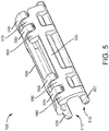
FIG. 5 is another perspective view of a three-axis symmetrical hinge assembly, according to some embodiments. -
FIG. 6 is a perspective view of a component of the hinge assembly ofFIG. 5 , according to some embodiments. -
FIG. 7 is another perspective view of an electronics enclosure assembly, according to some embodiments. -
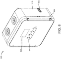
FIG. 8 is a perspective view of a refrigeration control unit, according to some embodiments. -
FIG. 9 is a perspective view of the hinge assembly ofFIG. 5 installed in the refrigeration control unit ofFIG. 8 , according to some embodiments. -
FIG. 10 is a perspective view of the hinge assembly ofFIG. 1 installed in another refrigeration control unit, according to some embodiments. -
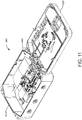
FIG. 11 is a perspective view of the hinge assembly ofFIG. 5 installed in the refrigeration control unit ofFIG. 10 , according to some embodiments. -
FIG. 12 is a front elevation view of a refrigeration control unit, according to some embodiments. -
FIG. 13 is another front elevation view of a refrigeration control unit, according to some embodiments. -
FIG. 14 is a perspective view of a refrigeration control unit, according to some embodiments. -
FIG. 15 is a block diagram of a refrigeration control unit, according to some embodiments. - Referring generally to FIGURES, disclosed herein are improvements to a refrigeration control unit. The refrigeration control unit includes various embodiments of a three-axis symmetrical hinge assembly. As discussed herein, three-axis symmetrical hinge assemblies are generally types of hardware configured to rotatably couple to an electronic device enclosure and to permit rotary and/or translational movement of the enclosure components relative to each other. For example, the hinge assembly may be actuated by a user (e.g., by moving one component of the enclosure assembly relative to another component) to open and close an electronics housing. The example implementations described herein provide a hinge assembly comprised of two identical hinge components. Features of the hinge components permit the hinge assembly to rotate about three separate axes.
- According to an example implementation illustrated by
FIGS. 1 and 2 , ahinge assembly 100 includes twohinge components 110 rotatably coupled together along acentral axis 112. As shown,assembly 100 has 180 degree rotational symmetry. In other words, onehinge component 110 may be rotated 180 degrees relative to theother hinge component 110 in order to mate the components with each other. Advantageously, no other parts (e.g., hardware, fasteners) are required to couple afirst hinge component 110 to asecond hinge component 110. -
Hinge component 110 is shown to include apin portion 120 and aleaf portion 130. As described in further detail with reference toFIGS. 3 and4 below,pin portion 120 may be configured to rotatably couple hinge assembly 100 to an electronics device enclosure via hinge receiving features. Theleaf portion 130 ofhinge component 110 terminates at afirst knuckle 140 and asecond knuckle 150. In some embodiments,hinge component 110 is fabricated from acetal resin, otherwise known under the trade name Delrin®. In other embodiments, hinge component may be fabricated from any suitable material (e.g., plastic, metal). In addition,hinge component 110 may be fabricated via any suitable process (e.g., injection molding, machining, 3D printing). -
First knuckle 140 is shown to include adetent feature 160, whilesecond knuckle 150 includes anindent feature 170.Detent feature 160 andindent feature 170 may be configured to rotatably couple twohinge components 110 to each other. For example, thedetent feature 160 of afirst hinge component 110 may be configured to fit (e.g., snap-fit) within theindent feature 170 of asecond hinge component 110, and vice versa. As shown, detent feature 160 may include a semi-spherically shaped protrusion, while indent feature 170 may include a semi-spherically shaped recess. However, in other embodiments, detent feature 160 andindent feature 170 may be any compatible shapes required to couplemultiple hinge components 110. - Turning now to
FIG. 3 , a view of anelectronics enclosure assembly 200 is depicted, according to an example embodiment. In some embodiments, theelectronics enclosure assembly 200 is a housing for a refrigeration control unit. As shown,enclosure assembly 200 may include afirst enclosure component 210 and asecond enclosure component 220. In various embodiments,first enclosure component 210 andsecond enclosure component 220 are representative of a front half and back half of a device housing, or alternatively, a top cover and a bottom cover of a device housing. - Both
first enclosure component 210 andsecond enclosure component 220 may include a plurality of lower hinge receiving features 230 and upper hinge receiving features 240. For example,hinge receiving features enclosure components enclosure components electronics enclosure assembly 200. - Referring now to
FIG. 4 , a view of installedhinge enclosure assembly 300 is shown, according to an example embodiment. As shown,assembly 300 includeshinge assembly 100 installed withinenclosure assembly 200. In some embodiments,hinge assembly 100 may be installed withinenclosure assembly 200 via a snap-fit assembly process. However, in other embodiments, a different assembly process and/or different means of retention (e.g., adhesives, fasteners, etc.) may be utilized to form installedhinge enclosure assembly 300. -
FIG. 4 demonstrates the three axes of rotation enabled via the installation ofhinge assembly 100 intoenclosure assembly 200. These axes include:central axis 112, which permits rotation of thehinge components 110 relative to each other;first pin axis 114, which permits rotation offirst enclosure component 210 relative to hingeassembly 100; and second pin axis 116 (not shown), which permits rotation ofsecond enclosure component 220 relative to hingeassembly 100. In some embodiments, in addition to rotational movement, the geometry ofhinge components 110 and the presence ofrotational axes first enclosure component 210 and thesecond enclosure component 220 in either a horizontal or a vertical direction. - Referring now to
FIGS. 5-6 , another example implementation of ahinge assembly 500 is depicted. Similar to hingeassembly 100,hinge assembly 500 includes twohinge components 510 rotatably coupled together along a central axis with 180 degree rotational symmetry. The extended length ofhinge assembly 500 as compared to hingeassembly 100 may be advantageous when joining large device enclosure components. - Like
hinge component 110,hinge component 510 is shown to include apin portion 520 and aleaf portion 530. As described in further detail with reference toFIGS. 7 and9 below,pin portion 520 may be configured to rotatably couple hinge assembly 500 to an electronics device enclosure via hinge receiving features. Theleaf portion 530 ofhinge component 510 terminates at afirst knuckle 540, asecond knuckle 550, athird knuckle 560, and afourth knuckle 570.First knuckle 540 andthird knuckle 560 are shown to include detent features 580, whilesecond knuckle 550 andfourth knuckle 570 are shown to include indent features 590. Detent features 580 and indent features 590 may be configured to rotatably couple twohinge components 510 to each other. - Turning now to
FIG. 7 , a view of anelectronics enclosure assembly 700 is depicted. In some embodiments, theelectronics enclosure assembly 700 is a housing for a refrigeration control unit. As shown,enclosure assembly 700 may include afirst enclosure component 710 and asecond enclosure component 720. Bothfirst enclosure component 710 andsecond enclosure component 720 may include a plurality of lower hinge receiving features 730 and upper hinge receiving features 740. For example,hinge receiving features components -
FIG. 8 depicts arefrigeration control unit 800. Refrigerationcontrol unit device 800 may be configured to control commercial refrigeration equipment, including walk-in refrigerators, coolers, and freezers installed in grocery stores, restaurants, and the like. In some embodiments, refrigeration control unit devices may also be used to control refrigeration and freezer cases for the display and distribution of food service products. As shown,refrigeration control unit 800 may include, among other components, afirst enclosure component 810, a universal serial bus (USB)port 815, asecond enclosure component 820, adisplay 830, and unit controls 840.Display 830 and unit controls 840 are described in further detail below with reference toFIGS. 12 and 13 . -
FIG. 9 depicts the interior ofrefrigeration control unit 800 with the electronic components (e.g., circuit card assemblies, connectors) not shown.First enclosure component 810 may be rotatably coupled tosecond enclosure component 820 via ahinge assembly 500. Similar to electronics enclosure assemblies described above,hinge assembly 500 is shown to couple to thefirst enclosure component 810 and thesecond enclosure component 820 via multiple upper and lower hinge receiving features 850 and 860. In some embodiments, hingecomponents 510 are configured to couple to upper and lower hinge receiving features 850 and 860 via a snap-fit assembly process. - Referring now to
FIGS 10 and11 , anotherrefrigeration control unit 1000 is depicted, according to an example embodiment. Similar torefrigeration control unit 800,refrigeration control unit 1000 is shown to include a firstenclosure housing component 1010, aUSB port 1015, a secondenclosure housing component 1020, adisplay 1040, and unit controls 1050. In contrast torefrigeration control unit 800,refrigeration control unit 1000 is further shown to include a thirdenclosure housing component 1030. Thirdenclosure housing component 1030 is configured to be rotatably coupled to secondenclosure housing component 1020 via a pair ofhinge assemblies 100. In some embodiments, thirdenclosure housing component 1030 may provide access to circuit breaker components located within therefrigeration control unit 1000 without requiring a user to open the entire refrigeration control unit (e.g., rotation of secondenclosure housing component 1020 relative to first enclosure housing component 1010).FIG. 11 depicts the interior ofrefrigeration control unit 1000. As shown, firstenclosure housing component 1010 is rotatably coupled tosecond enclosure component 1020 viahinge assembly 500. - Turning now to
FIGS. 12 and 13 , views of a refrigerationunit control device 1200 are shown, according to some embodiments. In some embodiments, refrigerationunit control device 1200 is identical or substantially similar torefrigeration control units unit control device 1200 includes, among other components, adisplay 1210 and unit controls 1220. - The
display 1210 may include a seven segment dot matrix LCD display combined with a standard 3-digit segmented area for temperature display. The seven segment dot matrix LCD display may be configured to permit plain language information to scroll across the display in a variety of languages. For example, inFIG. 12 , only the "CTRL" portion of the parameter "COLD ROOM CTRL" is visible at the top of thedisplay 1210. InFIG. 13 , which represents thedisplay 1210 while the parameter is in a different scroll position, the portion of the parameter reading "D ROOM C" is visible. In addition to the scrolling parameter portion, thehybrid display 1210 may also be configured to display a setpoint temperature and/or a current temperature of the refrigeration unit. For example, as shown inFIGS. 12-13 , the setpoint temperature of the unit may be 72° F, while the current temperature of the unit may be 73° F. - In addition to the
LCD display 1210,refrigeration control unit 1200 may include several touch screen controls 1220. In various embodiments, the touch screen controls 1220 may include a MENU/ESC control, a down arrow control, an up arrow control, and a SET control. The MENU/ESC control may be configured to allow a user to navigate through a menu structure. In some embodiments,refrigeration control unit 1200 may organize menu items into easy-to-navigate functional groupings ondisplay 1210 that are directly related to the control functionality of the refrigeration equipment. For example, these functional groupings may include Defrost Control, Alarming, System Set-up, Fan Control, and Temperature Control. In some embodiments, once a user has selected a functional group for programming, the user interface shown ondisplay 1210 will automatically advance to the next programmable parameter, ensuring that all available parameters for the refrigeration equipment are programmed. In various embodiments, the down and up arrow controls may be configured to permit a user to scroll through a list of options for each parameter, while the SET control may be configured to permit a user to select the desired option for each parameter. - Referring now to
FIG. 14 , another example implementation of arefrigeration control unit 1400 is depicted. Similar torefrigeration control units refrigeration control unit 1400 is shown to include adisplay head 1405 with adisplay 1410 and unit controls 1420. As shown, thedisplay head 1405 may be coupled to anelectronics unit 1425. Although smaller in form factor thanrefrigeration control units refrigeration control unit 1400 may be configured to perform many of the same functions asrefrigeration control units refrigeration control unit 1400 may be identical to the firmware ofrefrigeration control unit 800. - Turning now to
FIG. 15 , a block diagram of arefrigeration control unit 1500 is depicted, according to some embodiments. In various embodiments,refrigeration control unit 1500 is identical or substantially similar torefrigeration control units Refrigeration control unit 1500 is shown to include aprocessing circuit 1502.Processing circuit 1502 can be communicably connected toUSB interface 1508,display interface 1510, andcontrol interface 1512 such thatprocessing circuit 1502 and the various components thereof can send and receive data via interfaces 1508-1512. -
Processing circuit 1502 may includememory 1504 and aprocessor 1506.Processor 1506 can be implemented as a general purpose processor, an application specific integrated circuit (ASIC), one or more field programmable gate arrays (FPGAs), a group of processing components, or other suitable electronic processing components. Memory 1504 (e.g., memory, memory unit, storage device, etc.) may include one or more devices (e.g., RAM, ROM, Flash memory, hard disk storage, etc.) for storing data and/or computer code for completing or facilitating the various processes, layers and modules described in the present application.Memory 1504 can be or include volatile memory or nonvolatile memory.Memory 1504 may include database components, object code components, script components, or any other type of information structure for supporting the various activities and information structures described in the present application. According to some embodiments,memory 1504 is communicably connected toprocessor 1506 viaprocessing circuit 1502 and includes computer code for executing (e.g., by processingcircuit 1502 and/or processor 1506) one or more processes described herein. In various embodiments, the processing circuit may be communicably coupled to various components of the refrigeration equipment (not shown) and control signals transmitted to the refrigeration equipment from theprocessing circuit 1502 may modify an operating condition of the refrigeration equipment. -
Refrigeration control unit 1500 is further shown to include aUSB interface 1508, adisplay interface 1510, and acontrol interface 1512.USB interface 1508 may be communicably coupled to a USB port (e.g.,USB port 815, USB port 1015) accessible from the exterior of therefrigeration control unit 1500. In some embodiments,USB interface 1508 may be used to update control unit firmware. For example, as updates to the system become available, a user may obtain the updated firmware and upload it to controlunit 1500 viaUSB interface 1508.Display unit interface 1510 may be communicably coupled to a display (e.g.,display 830,display 1040, display 1410), whilecontrol interface 1512 may be communicably coupled to unit controls (e.g., touch screen controls 840, touch screen controls 1050, touch screen controls 1420). Based on data received from the unit controls via thecontrol interface 1512, theprocessing circuit 1502 may execute processes and output data (e.g., selected refrigeration unit parameters) that are displayed on theunit display 1510. - Numerous specific details are described to provide a thorough understanding of the disclosure. However, in certain instances, well-known or conventional details are not described in order to avoid obscuring the description. References to "some embodiments," "one embodiment," "an exemplary embodiment," and/or "various embodiments" in the present disclosure can be, but not necessarily are, references to the same embodiment and such references mean at least one of the embodiments.
- Alternative language and synonyms may be used for any one or more of the terms discussed herein. No special significance should be placed upon whether or not a term is elaborated or discussed herein. Synonyms for certain terms are provided. A recital of one or more synonyms does not exclude the use of other synonyms. The use of examples anywhere in this specification including examples of any terms discussed herein is illustrative only, and is not intended to further limit the scope and meaning of the disclosure or of any exemplified term. Likewise, the disclosure is not limited to various embodiments given in this specification.
- The elements and assemblies may be constructed from any of a wide variety of materials that provide sufficient strength or durability, in any of a wide variety of colors, textures, and combinations. Further, elements shown as integrally formed may be constructed of multiple parts or elements.
- As used herein, the word "exemplary" is used to mean serving as an example, instance or illustration. Any implementation or design described herein as "exemplary" is not necessarily to be construed as preferred or advantageous over other implementations or designs. Rather, use of the word exemplary is intended to present concepts in a concrete manner. Accordingly, all such modifications are intended to be included within the scope of the present disclosure. Other substitutions, modifications, changes, and omissions may be made in the design, operating conditions, and arrangement of the preferred and other exemplary implementations without departing from the scope of the appended claims.
- As used herein, the terms "approximately," "about," "substantially," and similar terms are intended to have a broad meaning in harmony with the common and accepted usage by those of ordinary skill in the art to which the subject matter of this disclosure pertains. It should be understood by those of skill in the art who review this disclosure that these terms are intended to allow a description of certain features described and claimed without restricting the scope of these features to the precise numerical ranges provided. Accordingly, these terms should be interpreted as indicating that insubstantial or inconsequential modifications or alterations of the subject matter described and claimed are considered to be within the scope of the invention as recited in the appended claims.
- As used herein, the term "coupled" means the joining of two members directly or indirectly to one another. Such joining may be stationary in nature or moveable in nature and/or such joining may allow for the flow of fluids, electricity, electrical signals, or other types of signals or communication between the two members. Such joining may be achieved with the two members or the two members and any additional intermediate members being integrally formed as a single unitary body with one another or with the two members or the two members and any additional intermediate members being attached to one another. Such joining may be permanent in nature or alternatively may be removable or releasable in nature.
- Although only a few embodiments have been described in detail in this disclosure, many modifications are possible (e.g., variations in sizes, dimensions, structures, shapes and proportions of the various elements, values of parameters, mounting arrangements, use of materials, colors, orientations, etc.). For example, the position of elements may be reversed or otherwise varied and the nature or number of discrete elements or positions may be altered or varied. Accordingly, all such modifications are intended to be included within the scope of the present disclosure. Other substitutions, modifications, changes, and omissions may be made in the design, operating conditions and arrangement of the exemplary embodiments without departing from the scope of the present disclosure.
- The present disclosure contemplates methods, systems and program products on any machine-readable media for accomplishing various operations. The embodiments of the present disclosure may be implemented using existing computer processors, or by a special purpose computer processor for an appropriate system, incorporated for this or another purpose, or by a hardwired system. Embodiments within the scope of the present disclosure include program products comprising machine-readable media for carrying or having machine-executable instructions or data structures stored thereon. Such machine-readable media can be any available media that can be accessed by a general purpose or special purpose computer or other machine with a processor. By way of example, such machine-readable media can comprise RAM, ROM, EPROM, EEPROM, CD-ROM or other optical disk storage, magnetic disk storage or other magnetic storage devices, or any other medium which can be used to carry or store desired program code in the form of machine-executable instructions or data structures and which can be accessed by a general purpose or special purpose computer or other machine with a processor. When information is transferred or provided over a network or another communications connection (either hardwired, wireless, or a combination of hardwired or wireless) to a machine, the machine properly views the connection as a machine-readable medium. Thus, any such connection is properly termed a machine-readable medium. Combinations of the above are also included within the scope of machine-readable media. Machine-executable instructions include, for example, instructions and data which cause a general purpose computer, special purpose computer, or special purpose processing machines to perform a certain function or group of functions.
- Although the figures may show a specific order of method steps, the order of the steps may differ from what is depicted. Also, two or more steps may be performed concurrently or with partial concurrence. Such variation will depend on the software and hardware systems chosen and on designer choice. All such variations are within the scope of the disclosure. Likewise, software implementations could be accomplished with standard programming techniques with rule based logic and other logic to accomplish the various connection steps, processing steps, comparison steps and decision steps.
Claims (15)
- A hinge assembly, comprising:- a first hinge component comprising a leaf portion terminating in a first knuckle and a second knuckle, the first knuckle comprising a first protrusion and the second knuckle comprising a first recess; and- a second hinge component, the second hinge component rotatably coupled to the first hinge component and structurally identical to the first hinge component;wherein the first protrusion of the first hinge component is configured to fit within the first recess of the second hinge component, and the first protrusion of the second hinge component is configured to fit within the first recess of the first hinge component.
- The hinge assembly of claim 1,
wherein at least one of the first hinge component and the second hinge component is fabricated from acetal resin. - The hinge assembly of claim 1 or 2,
wherein at least one of the first protrusion and the first recess has a substantially semi-spherical shape. - The hinge assembly of one of claims 1 to 3,
wherein the hinge assembly is configured to couple to an electronic device comprising a first device enclosure component and a second device enclosure component. - The hinge assembly of claim 4,
wherein the first hinge component is rotatably coupled to the first device enclosure component and the second hinge component is rotatably coupled to second device enclosure component. - The hinge assembly of claim 5,
wherein the first hinge component and the second hinge component each further comprise a pin member portion. - The hinge assembly of claim 6,
wherein the pin member portion is configured to permit the first hinge component and the second hinge component to pivotally couple to the first device enclosure component and the second device enclosure component via a snap fit assembly process. - The hinge assembly of one of claims 4 to 7,
wherein the electronic device is a refrigeration control unit. - The hinge assembly of claim 8,
wherein the refrigeration control unit comprises:- a plurality of touch screen controls configured to permit selection of refrigeration unit operating parameters;- a liquid crystal display; and- a processing circuit communicably coupled to the plurality of touch screen controls and the liquid crystal display. - The hinge assembly of claim 9,
wherein the processing circuit is configured to:- receive a selected refrigeration unit operating parameter via the plurality of touch screen controls; and- transmit a signal to display a plurality of selected refrigeration unit operating parameters in a scrolling display format on the liquid crystal display. - The hinge assembly of one of claims 8 to 10,
wherein the refrigeration control unit is configured to modify an operating condition of a walk-in refrigerator. - The hinge assembly of one of claims 8 to 10,
wherein the refrigeration control unit is configured to modify an operating condition of a cooler. - The hinge assembly of one of claims 8 to 10,
wherein the refrigeration control unit is configured to modify an operating condition of a freezer. - The hinge assembly of one of claims 1 to 13,
wherein the first hinge component and the second hinge component each further comprise a third knuckle and a fourth knuckle, the third knuckle comprising a second protrusion and the fourth knuckle comprising a second recess. - The hinge assembly of claim 14,
wherein the second protrusion of the first hinge component is configured to fit within the second recess of the second hinge component, and the second protrusion of the second hinge component is configured to fit within the second recess of the first hinge component.
Applications Claiming Priority (2)
| Application Number | Priority Date | Filing Date | Title |
|---|---|---|---|
| US201762451611P | 2017-01-27 | 2017-01-27 | |
| US15/727,462 US10760312B2 (en) | 2017-01-27 | 2017-10-06 | Refrigeration control unit with three-axis hinge assembly |
Publications (3)
| Publication Number | Publication Date |
|---|---|
| EP3355669A2 true EP3355669A2 (en) | 2018-08-01 |
| EP3355669A3 EP3355669A3 (en) | 2018-11-07 |
| EP3355669B1 EP3355669B1 (en) | 2021-08-18 |
Family
ID=61189211
Family Applications (1)
| Application Number | Title | Priority Date | Filing Date |
|---|---|---|---|
| EP18153610.3A Active EP3355669B1 (en) | 2017-01-27 | 2018-01-26 | Refrigeration control unit with three-axis hinge assembly |
Country Status (3)
| Country | Link |
|---|---|
| US (1) | US10760312B2 (en) |
| EP (1) | EP3355669B1 (en) |
| CN (1) | CN108397068B (en) |
Families Citing this family (11)
| Publication number | Priority date | Publication date | Assignee | Title |
|---|---|---|---|---|
| US10442580B2 (en) | 2016-11-10 | 2019-10-15 | Steven Murrill | Chemical storage container with locking hinge |
| CN108343668B (en) * | 2017-01-23 | 2020-11-06 | 漳州灿坤实业有限公司 | Rotating shaft mechanism and cooking device with same |
| USD895444S1 (en) * | 2018-01-19 | 2020-09-08 | Johnson Controls Technology Company | Display device |
| CN110671418B (en) * | 2018-07-02 | 2021-08-31 | 光宝电子(广州)有限公司 | Pivot structure and shell applying same |
| US10787846B2 (en) * | 2018-08-03 | 2020-09-29 | General Electric Company | Additively manufactured hinge assembly |
| CN109339606B (en) * | 2018-10-11 | 2020-09-11 | 赵崇良 | Self-adaptive three-axis hinge |
| DE102018132674A1 (en) * | 2018-12-18 | 2020-06-18 | Endress+Hauser Conducta Gmbh+Co. Kg | Wing hinge for a field device housing and field device housing with wing hinge |
| US12119505B2 (en) | 2019-07-29 | 2024-10-15 | Brightz, ltd. | Multi-purpose battery pack |
| CN111283641B (en) * | 2020-04-03 | 2023-06-27 | 上海美瑞实业有限公司 | Tool box |
| US20220045495A1 (en) * | 2020-08-06 | 2022-02-10 | Abb Schweiz Ag | Junction box assembly |
| DE102021120428A1 (en) | 2021-08-05 | 2023-02-09 | Endress+Hauser Conducta Gmbh+Co. Kg | Wing hinge for a field device housing and field device housing with wing hinge |
Family Cites Families (29)
| Publication number | Priority date | Publication date | Assignee | Title |
|---|---|---|---|---|
| US32482A (en) | 1861-06-04 | Conrad m | ||
| GB1057765A (en) | 1964-05-25 | 1967-02-08 | Sai Kheong Kwan | Improvements in or relating to hinges |
| US3268158A (en) | 1964-10-22 | 1966-08-23 | Elbert V Abbott | Strong box |
| FR2196684A5 (en) | 1972-08-16 | 1974-03-15 | See Jacques | |
| JPS5811741Y2 (en) * | 1978-04-28 | 1983-03-05 | 株式会社シマノ | Constant temperature container |
| US4213310A (en) * | 1979-04-03 | 1980-07-22 | Igloo Corporation | Thermal container with quick-release lid-mounted flask |
| US4336883A (en) * | 1980-06-09 | 1982-06-29 | Divajex | Insulated container |
| US4515421A (en) * | 1983-11-07 | 1985-05-07 | The Coleman Company, Inc. | Multiple use shelf for cooler |
| GB8528837D0 (en) | 1985-11-22 | 1985-12-24 | Frost Ltd F C | Concealed hinge mounting of doors |
| JP2506494Y2 (en) | 1989-11-02 | 1996-08-07 | 旭光学工業株式会社 | Image scanner cover mounting structure |
| US4966004A (en) * | 1989-11-06 | 1990-10-30 | Amana Refrigeration, Inc. | Electronic control mounting apparatus for refrigerator |
| FR2673971A1 (en) | 1991-03-11 | 1992-09-18 | Firac | Hinge with multiple axes of articulation and door equipped with such a hinge |
| US5551558A (en) * | 1994-07-01 | 1996-09-03 | Bureau; H. Lee | Combined portable container and collapsible table |
| US5865037A (en) * | 1996-08-30 | 1999-02-02 | Vesture Corporation | Insulated chest and method |
| US6026978A (en) * | 1999-02-11 | 2000-02-22 | Clegg; Geniel | Cooler |
| US6186351B1 (en) * | 1999-12-17 | 2001-02-13 | Frank Coyle | Portable salad cooler |
| US6408634B1 (en) | 2000-08-17 | 2002-06-25 | Jimex Corporation | Multi-chamber refrigeration system utilizing a single compressor and digital temperature controls |
| US6336552B1 (en) * | 2000-09-11 | 2002-01-08 | Rpm Industries, Inc. | Organizer for ammunition box |
| GB2385774B (en) | 2002-02-28 | 2005-06-22 | Sun Microsystems Inc | Rack-mounted module access |
| ITRM20030138U1 (en) * | 2003-07-31 | 2003-10-29 | Maurizio Fusco | TELEPHONE ALARM DEVICE TO REPORT THE DANGER OF DETERIORATION OF MEDICINAL PRODUCTS AND FOODSTUFFS STORED IN REFRIGERATORS, B |
| US7377125B2 (en) * | 2004-10-20 | 2008-05-27 | Cold Fusion Industries, Llc | Walk-in refrigerator/freezers and wine coolers for home use |
| US20080047287A1 (en) * | 2006-08-24 | 2008-02-28 | Jonathan Paul Ruppert | Refrigerator based audio-visual presentation and communication system |
| US8210387B2 (en) * | 2009-10-09 | 2012-07-03 | The Stanley Works Israel Ltd. | Organizer |
| CN201713165U (en) | 2010-06-29 | 2011-01-19 | 江南嘉捷电梯股份有限公司 | Elevator car operation panel |
| US9134053B2 (en) * | 2011-08-23 | 2015-09-15 | B/E Aerospace, Inc. | Vehicle refrigerator having a liquid line subcooled vapor cycle system |
| JP5666058B2 (en) | 2012-03-23 | 2015-02-12 | 三菱電機株式会社 | Electronics |
| DE202013103702U1 (en) | 2013-08-15 | 2013-08-27 | Emka Beschlagteile Gmbh & Co. Kg | Hinge with interlocking hinge wings |
| US20160187046A1 (en) * | 2014-12-31 | 2016-06-30 | Jeremy Chen | Cooler with integrated audio system and power station |
| US10501972B2 (en) | 2015-03-31 | 2019-12-10 | Follett Corporation | Refrigeration system and control system therefor |
-
2017
- 2017-10-06 US US15/727,462 patent/US10760312B2/en active Active
-
2018
- 2018-01-23 CN CN201810064156.4A patent/CN108397068B/en active Active
- 2018-01-26 EP EP18153610.3A patent/EP3355669B1/en active Active
Non-Patent Citations (1)
| Title |
|---|
| None |
Also Published As
| Publication number | Publication date |
|---|---|
| EP3355669B1 (en) | 2021-08-18 |
| EP3355669A3 (en) | 2018-11-07 |
| US10760312B2 (en) | 2020-09-01 |
| CN108397068B (en) | 2021-08-06 |
| CN108397068A (en) | 2018-08-14 |
| US20180216380A1 (en) | 2018-08-02 |
Similar Documents
| Publication | Publication Date | Title |
|---|---|---|
| US10760312B2 (en) | Refrigeration control unit with three-axis hinge assembly | |
| US7614567B2 (en) | Rotatable thermostat | |
| US9891664B2 (en) | Electronic device having standing unit | |
| EP3594067B1 (en) | Aircraft cabin apparatus including personal electronic device holder | |
| EP2823735B1 (en) | Temperature-controlled storage device with a display case door and a pivoting mullion | |
| EP2423778A2 (en) | Rotational hinge | |
| US11519653B2 (en) | Refrigerator with variable ice dispenser | |
| US20180245840A1 (en) | Refrigerator and camera system thereof | |
| EP3314352A1 (en) | Cylindrical dual axis hinge for electronic devices | |
| US11971212B2 (en) | Refrigerator with variable fluid dispenser | |
| US20140001941A1 (en) | Hinge mechanism and clamshell device thereof | |
| KR100549528B1 (en) | Refrigerator for displaying text data using pager system and control method thereof | |
| CN109768391B (en) | Antenna, antenna electric downtilt display system and transmission mechanism thereof | |
| US6741474B1 (en) | Electrical device with a revolvable display panel | |
| CN105531433A (en) | Household appliance with housing, door and door opening angle setting device | |
| US10034558B2 (en) | Product display systems and methods | |
| CN108206869B (en) | Method for switching display screen and mobile terminal | |
| US20190226756A1 (en) | Refrigeration control unit | |
| WO2020238930A1 (en) | Refrigerator dispenser control with multi-function control paddle | |
| CN213395801U (en) | Air conditioner indoor unit and air conditioner | |
| EP3564607A1 (en) | Refrigeration control unit | |
| AU2020442945A1 (en) | Refrigerator | |
| US20240402578A1 (en) | Pivoting camera assembly for a refrigerator appliance | |
| US20040139581A1 (en) | Rotation hinge module with two degree of freedom | |
| CN214670844U (en) | Get cupboard and order meal and get meal system with classification function |
Legal Events
| Date | Code | Title | Description |
|---|---|---|---|
| PUAI | Public reference made under article 153(3) epc to a published international application that has entered the european phase |
Free format text: ORIGINAL CODE: 0009012 |
|
| STAA | Information on the status of an ep patent application or granted ep patent |
Free format text: STATUS: REQUEST FOR EXAMINATION WAS MADE |
|
| 17P | Request for examination filed |
Effective date: 20180126 |
|
| AK | Designated contracting states |
Kind code of ref document: A2 Designated state(s): AL AT BE BG CH CY CZ DE DK EE ES FI FR GB GR HR HU IE IS IT LI LT LU LV MC MK MT NL NO PL PT RO RS SE SI SK SM TR |
|
| AX | Request for extension of the european patent |
Extension state: BA ME |
|
| PUAL | Search report despatched |
Free format text: ORIGINAL CODE: 0009013 |
|
| AK | Designated contracting states |
Kind code of ref document: A3 Designated state(s): AL AT BE BG CH CY CZ DE DK EE ES FI FR GB GR HR HU IE IS IT LI LT LU LV MC MK MT NL NO PL PT RO RS SE SI SK SM TR |
|
| AX | Request for extension of the european patent |
Extension state: BA ME |
|
| RIC1 | Information provided on ipc code assigned before grant |
Ipc: E05D 3/06 20060101ALI20181002BHEP Ipc: E05D 7/085 20060101ALI20181002BHEP Ipc: E05D 1/06 20060101ALI20181002BHEP Ipc: F25D 29/00 20060101ALI20181002BHEP Ipc: G06F 3/0484 20130101ALI20181002BHEP Ipc: E05D 7/10 20060101ALI20181002BHEP Ipc: H05K 5/02 20060101AFI20181002BHEP |
|
| STAA | Information on the status of an ep patent application or granted ep patent |
Free format text: STATUS: EXAMINATION IS IN PROGRESS |
|
| 17Q | First examination report despatched |
Effective date: 20201007 |
|
| GRAP | Despatch of communication of intention to grant a patent |
Free format text: ORIGINAL CODE: EPIDOSNIGR1 |
|
| STAA | Information on the status of an ep patent application or granted ep patent |
Free format text: STATUS: GRANT OF PATENT IS INTENDED |
|
| RIC1 | Information provided on ipc code assigned before grant |
Ipc: E05D 7/10 20060101ALI20210128BHEP Ipc: E05D 5/14 20060101ALI20210128BHEP Ipc: E05D 7/085 20060101ALI20210128BHEP Ipc: G06F 3/0484 20130101ALI20210128BHEP Ipc: E05D 3/06 20060101ALI20210128BHEP Ipc: F25D 29/00 20060101ALI20210128BHEP Ipc: H05K 5/02 20060101AFI20210128BHEP Ipc: E05D 7/12 20060101ALI20210128BHEP Ipc: E05D 1/06 20060101ALI20210128BHEP |
|
| INTG | Intention to grant announced |
Effective date: 20210226 |
|
| RIN1 | Information on inventor provided before grant (corrected) |
Inventor name: LUC, TAI P. Inventor name: WERT, TROY Inventor name: JERABEK, AARON Inventor name: WEICH, DEBRA L. Inventor name: BUSHONG, PHILIP L. Inventor name: BUTLER, TIM Inventor name: DEBOER, DAVE P. Inventor name: DODGE, VICTOR E. Inventor name: HENDERSON, KIRK |
|
| GRAS | Grant fee paid |
Free format text: ORIGINAL CODE: EPIDOSNIGR3 |
|
| GRAA | (expected) grant |
Free format text: ORIGINAL CODE: 0009210 |
|
| STAA | Information on the status of an ep patent application or granted ep patent |
Free format text: STATUS: THE PATENT HAS BEEN GRANTED |
|
| AK | Designated contracting states |
Kind code of ref document: B1 Designated state(s): AL AT BE BG CH CY CZ DE DK EE ES FI FR GB GR HR HU IE IS IT LI LT LU LV MC MK MT NL NO PL PT RO RS SE SI SK SM TR |
|
| REG | Reference to a national code |
Ref country code: GB Ref legal event code: FG4D |
|
| REG | Reference to a national code |
Ref country code: CH Ref legal event code: EP |
|
| REG | Reference to a national code |
Ref country code: DE Ref legal event code: R096 Ref document number: 602018021866 Country of ref document: DE |
|
| REG | Reference to a national code |
Ref country code: IE Ref legal event code: FG4D Ref country code: AT Ref legal event code: REF Ref document number: 1422826 Country of ref document: AT Kind code of ref document: T Effective date: 20210915 |
|
| RAP2 | Party data changed (patent owner data changed or rights of a patent transferred) |
Owner name: JOHNSON CONTROLS TYCO IP HOLDINGS LLP |
|
| REG | Reference to a national code |
Ref country code: LT Ref legal event code: MG9D |
|
| REG | Reference to a national code |
Ref country code: NL Ref legal event code: MP Effective date: 20210818 |
|
| REG | Reference to a national code |
Ref country code: AT Ref legal event code: MK05 Ref document number: 1422826 Country of ref document: AT Kind code of ref document: T Effective date: 20210818 |
|
| REG | Reference to a national code |
Ref country code: DE Ref legal event code: R081 Ref document number: 602018021866 Country of ref document: DE Owner name: JOHNSON CONTROLS TYCO IP HOLDINGS LLP, MILWAUK, US Free format text: FORMER OWNER: JOHNSON CONTROLS TECHNOLOGY COMPANY, AUBURN HILLS, MI, US |
|
| PG25 | Lapsed in a contracting state [announced via postgrant information from national office to epo] |
Ref country code: SE Free format text: LAPSE BECAUSE OF FAILURE TO SUBMIT A TRANSLATION OF THE DESCRIPTION OR TO PAY THE FEE WITHIN THE PRESCRIBED TIME-LIMIT Effective date: 20210818 Ref country code: RS Free format text: LAPSE BECAUSE OF FAILURE TO SUBMIT A TRANSLATION OF THE DESCRIPTION OR TO PAY THE FEE WITHIN THE PRESCRIBED TIME-LIMIT Effective date: 20210818 Ref country code: HR Free format text: LAPSE BECAUSE OF FAILURE TO SUBMIT A TRANSLATION OF THE DESCRIPTION OR TO PAY THE FEE WITHIN THE PRESCRIBED TIME-LIMIT Effective date: 20210818 Ref country code: ES Free format text: LAPSE BECAUSE OF FAILURE TO SUBMIT A TRANSLATION OF THE DESCRIPTION OR TO PAY THE FEE WITHIN THE PRESCRIBED TIME-LIMIT Effective date: 20210818 Ref country code: FI Free format text: LAPSE BECAUSE OF FAILURE TO SUBMIT A TRANSLATION OF THE DESCRIPTION OR TO PAY THE FEE WITHIN THE PRESCRIBED TIME-LIMIT Effective date: 20210818 Ref country code: BG Free format text: LAPSE BECAUSE OF FAILURE TO SUBMIT A TRANSLATION OF THE DESCRIPTION OR TO PAY THE FEE WITHIN THE PRESCRIBED TIME-LIMIT Effective date: 20211118 Ref country code: AT Free format text: LAPSE BECAUSE OF FAILURE TO SUBMIT A TRANSLATION OF THE DESCRIPTION OR TO PAY THE FEE WITHIN THE PRESCRIBED TIME-LIMIT Effective date: 20210818 Ref country code: LT Free format text: LAPSE BECAUSE OF FAILURE TO SUBMIT A TRANSLATION OF THE DESCRIPTION OR TO PAY THE FEE WITHIN THE PRESCRIBED TIME-LIMIT Effective date: 20210818 Ref country code: NO Free format text: LAPSE BECAUSE OF FAILURE TO SUBMIT A TRANSLATION OF THE DESCRIPTION OR TO PAY THE FEE WITHIN THE PRESCRIBED TIME-LIMIT Effective date: 20211118 Ref country code: PT Free format text: LAPSE BECAUSE OF FAILURE TO SUBMIT A TRANSLATION OF THE DESCRIPTION OR TO PAY THE FEE WITHIN THE PRESCRIBED TIME-LIMIT Effective date: 20211220 |
|
| PG25 | Lapsed in a contracting state [announced via postgrant information from national office to epo] |
Ref country code: PL Free format text: LAPSE BECAUSE OF FAILURE TO SUBMIT A TRANSLATION OF THE DESCRIPTION OR TO PAY THE FEE WITHIN THE PRESCRIBED TIME-LIMIT Effective date: 20210818 Ref country code: LV Free format text: LAPSE BECAUSE OF FAILURE TO SUBMIT A TRANSLATION OF THE DESCRIPTION OR TO PAY THE FEE WITHIN THE PRESCRIBED TIME-LIMIT Effective date: 20210818 Ref country code: GR Free format text: LAPSE BECAUSE OF FAILURE TO SUBMIT A TRANSLATION OF THE DESCRIPTION OR TO PAY THE FEE WITHIN THE PRESCRIBED TIME-LIMIT Effective date: 20211119 |
|
| PG25 | Lapsed in a contracting state [announced via postgrant information from national office to epo] |
Ref country code: NL Free format text: LAPSE BECAUSE OF FAILURE TO SUBMIT A TRANSLATION OF THE DESCRIPTION OR TO PAY THE FEE WITHIN THE PRESCRIBED TIME-LIMIT Effective date: 20210818 |
|
| PG25 | Lapsed in a contracting state [announced via postgrant information from national office to epo] |
Ref country code: DK Free format text: LAPSE BECAUSE OF FAILURE TO SUBMIT A TRANSLATION OF THE DESCRIPTION OR TO PAY THE FEE WITHIN THE PRESCRIBED TIME-LIMIT Effective date: 20210818 |
|
| REG | Reference to a national code |
Ref country code: DE Ref legal event code: R097 Ref document number: 602018021866 Country of ref document: DE |
|
| PG25 | Lapsed in a contracting state [announced via postgrant information from national office to epo] |
Ref country code: SM Free format text: LAPSE BECAUSE OF FAILURE TO SUBMIT A TRANSLATION OF THE DESCRIPTION OR TO PAY THE FEE WITHIN THE PRESCRIBED TIME-LIMIT Effective date: 20210818 Ref country code: SK Free format text: LAPSE BECAUSE OF FAILURE TO SUBMIT A TRANSLATION OF THE DESCRIPTION OR TO PAY THE FEE WITHIN THE PRESCRIBED TIME-LIMIT Effective date: 20210818 Ref country code: RO Free format text: LAPSE BECAUSE OF FAILURE TO SUBMIT A TRANSLATION OF THE DESCRIPTION OR TO PAY THE FEE WITHIN THE PRESCRIBED TIME-LIMIT Effective date: 20210818 Ref country code: EE Free format text: LAPSE BECAUSE OF FAILURE TO SUBMIT A TRANSLATION OF THE DESCRIPTION OR TO PAY THE FEE WITHIN THE PRESCRIBED TIME-LIMIT Effective date: 20210818 Ref country code: CZ Free format text: LAPSE BECAUSE OF FAILURE TO SUBMIT A TRANSLATION OF THE DESCRIPTION OR TO PAY THE FEE WITHIN THE PRESCRIBED TIME-LIMIT Effective date: 20210818 Ref country code: AL Free format text: LAPSE BECAUSE OF FAILURE TO SUBMIT A TRANSLATION OF THE DESCRIPTION OR TO PAY THE FEE WITHIN THE PRESCRIBED TIME-LIMIT Effective date: 20210818 |
|
| PLBE | No opposition filed within time limit |
Free format text: ORIGINAL CODE: 0009261 |
|
| STAA | Information on the status of an ep patent application or granted ep patent |
Free format text: STATUS: NO OPPOSITION FILED WITHIN TIME LIMIT |
|
| 26N | No opposition filed |
Effective date: 20220519 |
|
| PG25 | Lapsed in a contracting state [announced via postgrant information from national office to epo] |
Ref country code: IT Free format text: LAPSE BECAUSE OF FAILURE TO SUBMIT A TRANSLATION OF THE DESCRIPTION OR TO PAY THE FEE WITHIN THE PRESCRIBED TIME-LIMIT Effective date: 20210818 |
|
| PG25 | Lapsed in a contracting state [announced via postgrant information from national office to epo] |
Ref country code: SI Free format text: LAPSE BECAUSE OF FAILURE TO SUBMIT A TRANSLATION OF THE DESCRIPTION OR TO PAY THE FEE WITHIN THE PRESCRIBED TIME-LIMIT Effective date: 20210818 Ref country code: MC Free format text: LAPSE BECAUSE OF FAILURE TO SUBMIT A TRANSLATION OF THE DESCRIPTION OR TO PAY THE FEE WITHIN THE PRESCRIBED TIME-LIMIT Effective date: 20210818 |
|
| REG | Reference to a national code |
Ref country code: CH Ref legal event code: PL |
|
| GBPC | Gb: european patent ceased through non-payment of renewal fee |
Effective date: 20220126 |
|
| REG | Reference to a national code |
Ref country code: BE Ref legal event code: MM Effective date: 20220131 |
|
| PG25 | Lapsed in a contracting state [announced via postgrant information from national office to epo] |
Ref country code: LU Free format text: LAPSE BECAUSE OF NON-PAYMENT OF DUE FEES Effective date: 20220126 Ref country code: GB Free format text: LAPSE BECAUSE OF NON-PAYMENT OF DUE FEES Effective date: 20220126 |
|
| PG25 | Lapsed in a contracting state [announced via postgrant information from national office to epo] |
Ref country code: FR Free format text: LAPSE BECAUSE OF NON-PAYMENT OF DUE FEES Effective date: 20220131 Ref country code: BE Free format text: LAPSE BECAUSE OF NON-PAYMENT OF DUE FEES Effective date: 20220131 |
|
| PG25 | Lapsed in a contracting state [announced via postgrant information from national office to epo] |
Ref country code: LI Free format text: LAPSE BECAUSE OF NON-PAYMENT OF DUE FEES Effective date: 20220131 Ref country code: CH Free format text: LAPSE BECAUSE OF NON-PAYMENT OF DUE FEES Effective date: 20220131 |
|
| PG25 | Lapsed in a contracting state [announced via postgrant information from national office to epo] |
Ref country code: IE Free format text: LAPSE BECAUSE OF NON-PAYMENT OF DUE FEES Effective date: 20220126 |
|
| PG25 | Lapsed in a contracting state [announced via postgrant information from national office to epo] |
Ref country code: HU Free format text: LAPSE BECAUSE OF FAILURE TO SUBMIT A TRANSLATION OF THE DESCRIPTION OR TO PAY THE FEE WITHIN THE PRESCRIBED TIME-LIMIT; INVALID AB INITIO Effective date: 20180126 |
|
| PG25 | Lapsed in a contracting state [announced via postgrant information from national office to epo] |
Ref country code: MK Free format text: LAPSE BECAUSE OF FAILURE TO SUBMIT A TRANSLATION OF THE DESCRIPTION OR TO PAY THE FEE WITHIN THE PRESCRIBED TIME-LIMIT Effective date: 20210818 Ref country code: CY Free format text: LAPSE BECAUSE OF FAILURE TO SUBMIT A TRANSLATION OF THE DESCRIPTION OR TO PAY THE FEE WITHIN THE PRESCRIBED TIME-LIMIT Effective date: 20210818 |
|
| PG25 | Lapsed in a contracting state [announced via postgrant information from national office to epo] |
Ref country code: MT Free format text: LAPSE BECAUSE OF FAILURE TO SUBMIT A TRANSLATION OF THE DESCRIPTION OR TO PAY THE FEE WITHIN THE PRESCRIBED TIME-LIMIT Effective date: 20210818 |
|
| PG25 | Lapsed in a contracting state [announced via postgrant information from national office to epo] |
Ref country code: TR Free format text: LAPSE BECAUSE OF FAILURE TO SUBMIT A TRANSLATION OF THE DESCRIPTION OR TO PAY THE FEE WITHIN THE PRESCRIBED TIME-LIMIT Effective date: 20210818 |
|
| PGFP | Annual fee paid to national office [announced via postgrant information from national office to epo] |
Ref country code: DE Payment date: 20260127 Year of fee payment: 9 |