EP3355577A1 - Integral image processing device and vehicular lamp using same - Google Patents
Integral image processing device and vehicular lamp using same Download PDFInfo
- Publication number
- EP3355577A1 EP3355577A1 EP16849050.6A EP16849050A EP3355577A1 EP 3355577 A1 EP3355577 A1 EP 3355577A1 EP 16849050 A EP16849050 A EP 16849050A EP 3355577 A1 EP3355577 A1 EP 3355577A1
- Authority
- EP
- European Patent Office
- Prior art keywords
- image
- lens array
- denotes
- processing apparatus
- image processing
- Prior art date
- Legal status (The legal status is an assumption and is not a legal conclusion. Google has not performed a legal analysis and makes no representation as to the accuracy of the status listed.)
- Granted
Links
Images





Classifications
-
- G—PHYSICS
- G02—OPTICS
- G02B—OPTICAL ELEMENTS, SYSTEMS OR APPARATUS
- G02B30/00—Optical systems or apparatus for producing three-dimensional [3D] effects, e.g. stereoscopic images
- G02B30/20—Optical systems or apparatus for producing three-dimensional [3D] effects, e.g. stereoscopic images by providing first and second parallax images to an observer's left and right eyes
- G02B30/26—Optical systems or apparatus for producing three-dimensional [3D] effects, e.g. stereoscopic images by providing first and second parallax images to an observer's left and right eyes of the autostereoscopic type
- G02B30/27—Optical systems or apparatus for producing three-dimensional [3D] effects, e.g. stereoscopic images by providing first and second parallax images to an observer's left and right eyes of the autostereoscopic type involving lenticular arrays
-
- F—MECHANICAL ENGINEERING; LIGHTING; HEATING; WEAPONS; BLASTING
- F21—LIGHTING
- F21S—NON-PORTABLE LIGHTING DEVICES; SYSTEMS THEREOF; VEHICLE LIGHTING DEVICES SPECIALLY ADAPTED FOR VEHICLE EXTERIORS
- F21S43/00—Signalling devices specially adapted for vehicle exteriors, e.g. brake lamps, direction indicator lights or reversing lights
- F21S43/20—Signalling devices specially adapted for vehicle exteriors, e.g. brake lamps, direction indicator lights or reversing lights characterised by refractors, transparent cover plates, light guides or filters
- F21S43/26—Refractors, transparent cover plates, light guides or filters not provided in groups F21S43/235 - F21S43/255
-
- H—ELECTRICITY
- H04—ELECTRIC COMMUNICATION TECHNIQUE
- H04N—PICTORIAL COMMUNICATION, e.g. TELEVISION
- H04N13/00—Stereoscopic video systems; Multi-view video systems; Details thereof
- H04N13/20—Image signal generators
- H04N13/275—Image signal generators from three-dimensional [3D] object models, e.g. computer-generated stereoscopic image signals
-
- H—ELECTRICITY
- H04—ELECTRIC COMMUNICATION TECHNIQUE
- H04N—PICTORIAL COMMUNICATION, e.g. TELEVISION
- H04N13/00—Stereoscopic video systems; Multi-view video systems; Details thereof
- H04N13/30—Image reproducers
- H04N13/302—Image reproducers for viewing without the aid of special glasses, i.e. using autostereoscopic displays
-
- H—ELECTRICITY
- H04—ELECTRIC COMMUNICATION TECHNIQUE
- H04N—PICTORIAL COMMUNICATION, e.g. TELEVISION
- H04N13/00—Stereoscopic video systems; Multi-view video systems; Details thereof
- H04N13/30—Image reproducers
- H04N13/302—Image reproducers for viewing without the aid of special glasses, i.e. using autostereoscopic displays
- H04N13/307—Image reproducers for viewing without the aid of special glasses, i.e. using autostereoscopic displays using fly-eye lenses, e.g. arrangements of circular lenses
Definitions
- Embodiments relate to an integral image processing apparatus and a vehicle lamp using the same.
- a 3D stereoscopic image may be seen by a stereoscopic visual principle of the left eye and the right eye. Due to the difference between the two eyes, that is, due to the two eyes being separated by about 65 mm, the left eye and the right eye see slightly differently images. Thus, the difference between images caused by the difference in location between the two eyes is referred to as binocular disparity.
- a stereoscopic image display apparatus uses such binocular disparity to cause the user's left eye to see only a left view image and the user's right eye to see only a right view image, so that the user feels binocular disparity and, as a result, the user feels stereoscopic perception. That is, the left and right eyes view different 2D images and the two images are transmitted to the brain through the retinas. The brain combines the images and feels depth perception (or stereoscopic perception) or reality perception. This technology is called stereography.
- Integral imaging proposed by Lippmann in 1908, has advantages of providing full parallax and successive observation perspectives like holographic technology which is 3D display technology.
- glasses or other tools are not needed to see a stereoscopic image and a lens array consisting of a plurality of individual lenses is used to express a 3D stereoscopic image having a specific depth within a predetermined volume from all two-dimensional (2D) elemental images. That is, according to the integral imaging technology, the user may see a 3D stereoscopic image formed within a predetermined volume without eye fatigue and the user may feel as though they are seeing an actual 3D object.
- a conventional integral image processing apparatus adopting the integral imaging technology includes a pickup unit and a display (or reproduction or restoration) unit.
- the pickup unit stores various image information of a 3D object as an entire elemental image by use of a capture device such as a lens array or a camera. That is, the entire elemental image passing through the lens array of the pickup unit is stored in the pickup unit.
- the display unit may display the entire elemental image stored in the pickup unit on a display panel which is a type of a liquid crystal panel and image information of the entire elemental image passes through the lens array to display a 3D stereoscopic image (or an integrated image) in space.
- the display unit since the display unit necessarily includes a display panel, the conventional integral image processing apparatus has an increased volume.
- An embodiment provides an integral image processing apparatus having small volume and a vehicle lamp using the same.
- an integral image processing apparatus including a display unit configured to reproduce an entire elemental image for a 3-dimensional (3D) object as a 3D image, wherein the display unit includes: a light source; and a reproduction lens array for integrating a plurality of individual elemental images, which are included in a patterned image obtained by patterning the entire elemental image and constitute the entire elemental image, and reproducing the individual elemental images as a stereoscopic image.
- the display unit may include a pattern of the patterned image and may further include a pattern film disposed between the light source and the reproduction lens array.
- the reproduction lens array may include a first plane facing the light source; and a second plane facing the reproduced stereoscopic image from the opposite side of the first plane.
- the pattern of the patterned image may be transferred to the first plane and then may be engraved on the first plane.
- the pattern of the patterned image may be engraved on the first plane of the reproduction lens array in the form of roughness or in the form of intaglio.
- the integral image processing apparatus may further include a pickup unit configured to generate the patterned image.
- the pickup unit may include a pickup lens array configured to cause a plurality of rays emitted from the 3D object to pass therethrough to generate the plural individual elemental images, and the entire elemental image consisting of the plural individual elemental images passing through the pickup lens array may be engraved on the pattern film as the pattern of the patterned image.
- the pickup lens array may have the same characteristics as the reproduction lens array.
- the pickup unit may model the 3D object, estimate an illuminance value of a pixel included in each of the plural individual elemental images after the modeled result passes through a pickup lens array, and generate data for an illuminance value with respect to coordinates of each pixel as the patterned image.
- a first resolution of the reproduced stereoscopic image may be inversely proportional to the pixel size of the reproduced image.
- the size of a unit lens constituting the reproduction lens array may be less than 1 mm to 2 mm or may be 5 mm to 10 mm.
- a unit lens constituting the reproduction lens array may include a fly-eye lens.
- a lamp used in a vehicle including the integral image processing apparatus.
- an integral image processing apparatus includes an entire picked-up elemental image in a pattern film or engraves a pattern of a patterned image on the back of a reproduction lens array, so that the volume of the integral image processing apparatus can be reduced. If the integral image processing apparatus is applied to a lamp of a vehicle such as a tail lamp, a stereoscopic image is provided to other vehicles behind the vehicle to provide high visibility and sophisticated design.
- relational terms such as “on”/"upper part”/"above”, “under”/”lower part”/”below,” and the like, are used solely to distinguish one entity or element from another entity or element without necessarily requiring or implying any physical or logical relationship or order between such entities or elements.
- an integral image processing apparatus 100 will be described with reference to the attached drawings.
- the imaging processing apparatus 100 using the Cartesian coordinate system (x-axis, y-axis, and z-axis) is described.
- the image processing apparatus 100 can be described using other coordinate systems.
- the x-axis, the y-axis, and the x-axis are orthogonal according to the Cartesian coordinate system, embodiments are not limited thereto. In other words, the x-axis, the y-axis, and z-axis may not be orthogonal and may cross.
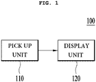
- FIG. 1 is a block diagram of the integral image processing apparatus 100 according to an embodiment.
- the integral image processing apparatus may include a pickup unit 110 and a display unit (or a reproduction unit) 120.
- the pickup unit 110 generates an entire elemental image for a 3D object OB and patterns the generated entire elemental image. Therefore, the patterned image generated from the pickup unit 110 is transmitted to the display unit 120 in various manners which will be described later.
- the entire elemental image may consist of a plurality of individual elemental images.
- FIG. 2 is a view conceptually illustrating an embodiment 110A of the pickup unit 110 illustrated in FIG. 1 .
- FIG. 2 shows a 2D plane of the y-axis and the z-axis, a 3D object OB is represented as a perspective view to aid in understanding of the embodiment.
- the pickup unit 110A may include a lens array (hereinafter, referred to as a "pickup lens array”) 112 and a pattern film 114.
- a lens array hereinafter, referred to as a "pickup lens array”
- a pattern film 114 may be included in the pickup unit 110A.
- the pickup lens array 112 causes a plurality of rays generated from a 3D object (or an object) OB to pass therethrough.
- the pickup lens array 112 may include a plurality of individual lenses.
- a plurality of individual elemental images of the 3D object OB seen from various directions in space is generated by the plural individual lenses.
- An individual elemental image is a 2D basic image for enabling a user to see the 3D object OB.
- the plural individual elemental images may have a uniform size.
- the entire elemental image consisting of a plurality of individual elemental images, each of which passes through each individual lens of the pickup lens array 112, may reach the pattern film 114 and may be engraved as a pattern of the patterned image.
- the pattern film 114 may be polyethylene terephthalate (PET) but embodiments are not limited thereto.
- the pickup unit stores the entire elemental image in an imaging device.
- the entire elemental image may be stored in the pattern film 114 in the form of a pattern (i.e., may be engraved). In this way, the patterned image for the 3D object OB may be physically generated.
- the pickup unit 110 may model the 3D object OB and estimate an illuminance value of a pixel included in each of the plural individual elemental images after the modeled object passes through the pickup lens array, thereby generating data for the illuminance value with respect to coordinates of each pixel as the patterned image.
- the entire elemental image may be generated by computer-generated integral imaging (CGII) using computer graphics. That is, the data for the illuminance value with respect to coordinates of the entire elemental image consisting of the plural individual elemental images for the 3D object OB may be generated as the patterned image by a computer algorithm.
- the patterned image for the 3D object OB may be programmatically generated.
- the patterned image may be generated in various ways without being limited to the above-described two embodiments. That is, the integral image processing apparatus 100 according to an embodiment may not include the pickup unit 110. In this case, a predefined patterned image may be provided to the display unit 120.
- the entire elemental image may be a video image (or active image) for the 3D object OB or may be a still image. That is, according to an application of the integral image processing apparatus 100 of an embodiment, various still images may be generated as the patterned image.
- FIGS. 3a to 3d are views illustrating a patterned image and a stereoscopic image.
- FIG. 3a is a front view exemplarily illustrating a 3D object OB
- FIG. 3b is a perspective view exemplarily illustrating the 3D object OB illustrated in FIG. 3a .
- FIG. 3c exemplarily illustrates a patterned image
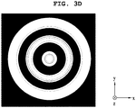
- FIG. 3d exemplarily illustrates a stereoscopic image.
- the 3D object OB has a cylindrical shape
- embodiments are not limited thereto.
- the patterned image may have a shape illustrated in FIG. 3c .
- a pattern of the patterned image illustrated in FIG. 3c may be engraved on the pattern film 114 or may be generated as data by a program.
- the display unit 120 may reproduce the entire elemental image for the 3D object OB as a 3D image. That is, the display unit 120 may reproduce the 3D stereoscopic image from the patterned image generated from the pickup unit 110 illustrated in FIG. 1 or from a predefined patterned image. If the patterned image is as illustrated in FIG. 3c and the 3D object OB is as illustrated in FIGS. 3a and 3b , the stereoscopic image illustrated in FIG. 3d may be reproduced by the display unit 120.
- FIG. 4 is a view conceptually illustrating an embodiment 120A of the display unit 120 illustrated in FIG. 1 .
- the display unit 120A may include a light source 122, a pattern film 124, and a lens array (hereinafter, referred to as a "reproduction lens array") 126.
- the light source 122 emits light towards the pattern film 124.
- the light source 122 may emit scattered light but embodiments are not limited to the types of light emitted from the light source 122.
- a backlight unit BLU
- BLU backlight unit
- the pattern film 124 illustrated in FIG. 4 may be the pattern film 114 illustrated in FIG. 2 . As described above with reference to FIG. 2 , if the entire elemental image for the 3D object OB is patterned and a pattern of the patterned image is engraved on the pattern film 114, the pattern film 114 may be used in the display unit 120A.
- the pattern film 124 illustrated in FIG. 4 may be disposed between the light source 122 and the reproduction lens array 126 but embodiments are not limited thereto.
- a plurality of individual elemental images included in the patterned image may be integrated so as to be reproduced as a stereoscopic image RI. That is, individual elemental images of the 3D object OB constituting the entire elemental image included in the patterned image are integrated while passing through the reproduction lens array 126, thereby being reproduced as the stereoscopic image. To this end, light may be emitted from the light source 122.
- the reproduction lens array 126 illustrated in FIG. 4 and the pickup lens array 112 illustrated in FIG. 2 may have the same characteristics.
- the pickup and reproduction lens arrays 112 and 126 illustrated respectively in FIGS. 2 and 4 may have the following similar characteristics.
- a first separation distance g between the pattern film 124 and the reproduction lens array 126 illustrated in FIG. 4 may be equal to a separation distance g' between the pickup lens array 112 and the pattern film 114 illustrated in FIG. 2 .
- the first separation distance g may correspond to a separation distance to the lens array 126 from an outer plane SO of the pattern film 124 facing the reproduction lens array 126.
- a second separation distance a between the reproduction lens array 126 illustrated in FIG. 4 and a center depth plane (CDP) (or a reference depth plane) of a reproduced stereoscopic image RI may be equal to a separation distance a' between the 3D object OB and the pickup lens array 112 illustrated in FIG. 2 .
- ⁇ denotes the size of a unit pixel of a patterned image having a pattern engraved on the pattern film 124.
- the first separation distance g and the second separation distance a illustrated in FIG. 4 may be determined as indicated by Equation 2 according to the first resolution R 1 of the reproduced stereoscopic image and a second resolution R D of a patterned image having a pattern engraved on the pattern film 124.
- g a R I R D
- Equation 3 the second resolution R D is determined by Equation 3.
- R D 1 ⁇
- the first resolution R I is adjusted by adjusting the first and second separation distances g and a.
- the number of lenses included in the reproduction lens array 126 illustrated in FIG. 4 may be equal to the number of lenses included in the pickup lens array 112 illustrated in FIG. 2 .
- a unit lens constituting each of the reproduction lens array 126 illustrated in FIG. 4 and the pickup lens array 112 illustrated in FIG. 2 may be a fly-eye lens but embodiments are not limited to the types of the unit lens.
- a size p of a unit lens included in the reproduction lens array 126 illustrated in FIG. 4 may be equal to a size p' of a unit lens included in the pickup lens array 112 included in FIG. 2 .
- the size p of each unit lens constituting the reproduction lens array 126 may be 2 mm or less but embodiments are not limited thereto.
- the size p of each unit lens constituting the reproduction lens array 126 may be 5 mm or more but embodiments are not limited thereto.
- the height of an individual integral image processing apparatus may be limited to a maximum of 15 mm although it may be different according to the construction of the tail lamp.
- the size p of each unit lens is less than 1 mm, a view angle is remarkably reduced to 15 degrees or less and, if the size p of each unit lens is greater than 10 mm, it is difficult to secure the depth perception of 30 mm or more.
- the size of the unit lens may have a range of 1 mm to 2 mm and, if the first resolution takes priority over the stereoscopic perception, the size of the unit lens may have a range of 5 mm to 10 mm.
- embodiments are not limited thereto.
- a view angle ⁇ of the reproduced stereoscopic image RI may be determined as indicated by Equation 4.
- tan ⁇ 2 p 2 g
- the view angle ⁇ can be adjusted according to the size p of the unit lens included in the reproduction lens array 126 and the first separation distance g.
- a depth ⁇ z of the reproduced image RI may be determined as indicated by Equation 5.
- ⁇ z 2 a p ⁇ I
- ⁇ I denotes a pixel size of the reproduced stereoscopic image RI and may be represented by Equation 6.
- ⁇ I a g ⁇
- the depth ⁇ z of the reproduced image can be adjusted by adjusting the size p of the unit lens and the first and second separation distances g and a in a state in which the second resolution R D is fixed.
- Equation 7 the second resolution R D may be expressed as indicated by Equation 8.
- the depth ⁇ z of the reproduced image RI may be defined by a first marginal depth plane MDP1 and a second marginal depth plane MDP2. Therefore, the depth ⁇ z of the reproduced image RI expressed as indicated by Equation 5 may be an interval between the first marginal depth plane MDP1 and the second marginal depth plane MDP2 in the z-axis direction. As the depth ⁇ z of the reproduced image RI increases, the stereoscopic sense of the reproduced image RI may also increase.
- a CDP of a stereoscopic image RI which is mentioned when defining the second separation distance a may be any one point on a CDP located at the middle between the first marginal depth plane MDP1 and the second marginal depth plane MDP2.
- FIG. 5 is a view conceptually illustrating another embodiment 120B of the display unit 120 illustrated in FIG. 1 .
- the display unit 120B may include a light source 122 and a reproduction lens array 126 as illustrated in FIG. 5
- the reproduction lens array 126 may include a first plane S1 and a second plane S2.
- the first plane S1 corresponds to the back surface of the reproduction lens array 126 facing the light source 122 and the second plane S2 corresponds to the front surface of the reproduction lens array 126 facing a reproduced stereoscopic image RI from the opposite side of the first plane S1.
- the display unit 120B illustrated in FIG. 5 does not include the pattern film 124.
- a pattern 125 of a patterned image corresponding to an entire elemental image for a 3D object OB may be transferred and engraved on the first plane S1 of the reproduction lens array 126.
- the display unit 120B illustrated FIG. 5 is the same as the display unit 120A illustrated in FIG. 4 , a repetitive description will be omitted.
- FIGS. 6A to 6C illustrate various shapes of the reproduction lens array 126 illustrated in FIGS. 4 and 5 .
- FIG. 6A is a right side view of the reproduction lens array 126
- FIG. 6B is a front view of the reproduction lens array 126
- FIG. 6C is a left side view of the reproduction lens array 126.
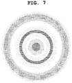
- FIG. 7 exemplarily illustrates a pattern of a patterned image transferred on the reproduction lens array 126.
- the pattern of the patterned image as illustrated in FIG. 7 may be engraved on the first plane S1 of the reproduction lens array 126 illustrated in FIG. 6c.
- the pattern of the patterned image may be engraved on the first plane S1 of the reproduction lens array 126 in the form of roughness or intaglio.
- the light source 122 is disposed in contact with the pattern 125 of the patterned image engraved on the first plane S1 of the reproduction lens array 126 as illustrated in FIG. 5 , embodiments are not limited thereto. That is, according to another embodiment, the light source 122 may be disposed separately from the pattern 125 of the patterned image in the z-axis direction.
- the pattern of the patterned image is engraved on the pattern film 124, whereas, in the display unit 120B illustrated in FIG. 4 , the pattern 125 of the patterned image is engraved on the first plane S1 of the reproduction lens array 126.
- the first separation distance g, the second separation distance a, the view angle ⁇ , a maximum value max( ⁇ z) of the depth of the reproduced image, and the pixel size ⁇ I of the reproduced image RI may have various values as shown in Table 1 according to the above-described equations.
- a focus distance f of the reproduction lens array 126 is decreased from 10 mm of CASE 1 to 5 mm of CASE 3, it can be appreciated that the view angle ⁇ is increased, similar to CASE 2, and the stereoscopic sense (max( ⁇ z)) is lower than that of CASE 2 but a width g in the z-axis direction of the display unit 120 becomes thinner.
- the size ⁇ of a pixel included in a patterned image is increased from 0.3 mm of CASE 1 to 1 mm of CASE 4, it can be appreciated that the view angle ⁇ is the same as that of CASE 1 and the stereoscopic perception (max( ⁇ z)) is increased above CASE 1, 2, or 3.
- the view angle ⁇ and the stereoscopic perception (max( ⁇ z)) can be adjusted by adjusting the focus distance f of the reproduction lens array 126, the size p of each of a plurality of unit lenses, and the size ⁇ of a pixel included in an image pattern. Accordingly, the view angle ⁇ and the stereoscopic perception (max( ⁇ z)) can be satisfied in fields to which the above-described integral image processing apparatus 100 is applied by adjusting the focus distance f of the reproduction lens array 126, the size p of each of a plurality of unit lenses, and the size ⁇ of a pixel included in a patterned image.
- the integral image processing apparatus may be applied to various fields. Accordingly, if the integral image processing apparatus 100 includes only the display unit 120, 120A, or 120B without including the pickup unit 110, the display unit 120, 120A, or 120B may be applied to various fields.
- the display units 120, 120A, and 120B may be used for vehicle lamps such as a tail lamp, a position lamp, and a brake lamp.
- FIG. 8 is a view illustrating an example applied to the integral image processing apparatus 100 according to an embodiment.
- the display unit 120B of the integral image processing apparatus 100 illustrated in FIG. 5 may be applied to a tail lamp of a vehicle 200 as illustrated in FIG. 8 .
- the display unit 120A illustrated in FIG. 4 instead of the display unit 120B illustrated in FIG. 5 , may be applied to the tail lamp of the vehicle 200.
- the stereoscopic image RI may be reproduced as illustrated in FIG. 3d even in a space separated from the tail of the vehicle 200.
- the integral image processing apparatus 100 is applied to a tail lamp of the vehicle as illustrated in FIG. 8 , high visibility can be provided by providing a stereoscopic image to other vehicles behind the vehicle 200 and a sophisticated design can be provided.
- the integral image processing apparatus includes an entire picked-up elemental image in a pattern film or a pattern of a patterned image is engraved on the back of the reproduction lens array so that the volume of the integral image processing apparatus can be reduced because a display panel is not needed in the display panel. If the integral image processing apparatus is applied to a tail lamp of a vehicle, high visibility can be provided by providing a stereoscopic image to other vehicles behind the vehicle and a sophisticated design can be provided.
Landscapes
- Engineering & Computer Science (AREA)
- Multimedia (AREA)
- Signal Processing (AREA)
- General Engineering & Computer Science (AREA)
- Physics & Mathematics (AREA)
- General Physics & Mathematics (AREA)
- Optics & Photonics (AREA)
- Stereoscopic And Panoramic Photography (AREA)
Abstract
Description
- Embodiments relate to an integral image processing apparatus and a vehicle lamp using the same.
- Recently, many studies on recognition of a 3-dimensional (3D) object and system implementation have been conducted.
- Generally, a 3D stereoscopic image may be seen by a stereoscopic visual principle of the left eye and the right eye. Due to the difference between the two eyes, that is, due to the two eyes being separated by about 65 mm, the left eye and the right eye see slightly differently images. Thus, the difference between images caused by the difference in location between the two eyes is referred to as binocular disparity.
- A stereoscopic image display apparatus uses such binocular disparity to cause the user's left eye to see only a left view image and the user's right eye to see only a right view image, so that the user feels binocular disparity and, as a result, the user feels stereoscopic perception. That is, the left and right eyes view different 2D images and the two images are transmitted to the brain through the retinas. The brain combines the images and feels depth perception (or stereoscopic perception) or reality perception. This technology is called stereography.
- However, when the user sees a stereoscopic image using binocular disparity, the user may experience dizziness and eye fatigue due to the difference between two images and mismatch of a focusing function of the eyes. Therefore, substantial research into applying integral imaging techniques to solve problems of stereography has been conducted recently.
- Integral imaging, proposed by Lippmann in 1908, has advantages of providing full parallax and successive observation perspectives like holographic technology which is 3D display technology. According to the integral imaging technology, glasses or other tools are not needed to see a stereoscopic image and a lens array consisting of a plurality of individual lenses is used to express a 3D stereoscopic image having a specific depth within a predetermined volume from all two-dimensional (2D) elemental images. That is, according to the integral imaging technology, the user may see a 3D stereoscopic image formed within a predetermined volume without eye fatigue and the user may feel as though they are seeing an actual 3D object.
- A conventional integral image processing apparatus adopting the integral imaging technology includes a pickup unit and a display (or reproduction or restoration) unit.
- The pickup unit stores various image information of a 3D object as an entire elemental image by use of a capture device such as a lens array or a camera. That is, the entire elemental image passing through the lens array of the pickup unit is stored in the pickup unit. The display unit may display the entire elemental image stored in the pickup unit on a display panel which is a type of a liquid crystal panel and image information of the entire elemental image passes through the lens array to display a 3D stereoscopic image (or an integrated image) in space. To this end, since the display unit necessarily includes a display panel, the conventional integral image processing apparatus has an increased volume.
- An embodiment provides an integral image processing apparatus having small volume and a vehicle lamp using the same.
- According to an embodiment, provided herein is an integral image processing apparatus including a display unit configured to reproduce an entire elemental image for a 3-dimensional (3D) object as a 3D image, wherein the display unit includes: a light source; and a reproduction lens array for integrating a plurality of individual elemental images, which are included in a patterned image obtained by patterning the entire elemental image and constitute the entire elemental image, and reproducing the individual elemental images as a stereoscopic image.
- For example, the display unit may include a pattern of the patterned image and may further include a pattern film disposed between the light source and the reproduction lens array.
- For example, the reproduction lens array may include a first plane facing the light source; and a second plane facing the reproduced stereoscopic image from the opposite side of the first plane.
- For example, the pattern of the patterned image may be transferred to the first plane and then may be engraved on the first plane.
- For example, the pattern of the patterned image may be engraved on the first plane of the reproduction lens array in the form of roughness or in the form of intaglio.
- For example, the integral image processing apparatus may further include a pickup unit configured to generate the patterned image.
- For example, the pickup unit may include a pickup lens array configured to cause a plurality of rays emitted from the 3D object to pass therethrough to generate the plural individual elemental images, and the entire elemental image consisting of the plural individual elemental images passing through the pickup lens array may be engraved on the pattern film as the pattern of the patterned image.
- For example, the pickup lens array may have the same characteristics as the reproduction lens array.
- For example, the pickup unit may model the 3D object, estimate an illuminance value of a pixel included in each of the plural individual elemental images after the modeled result passes through a pickup lens array, and generate data for an illuminance value with respect to coordinates of each pixel as the patterned image.
- For example, a first separation distance between the pattern film and the reproduction lens array may be determined as follows according to a first resolution of the reproduced stereoscopic image:

where g denotes the first separation distance, RI denotes the first resolution, a denotes a second separation distance between the reproduction lens array and a center of the reproduced stereoscopic image, and δ denotes a size of a unit pixel of the patterned image. - For example, a first separation distance between the pattern film and a reproduction lens array and the second separation distance between the reproduction lens array and a center of the reproduced stereoscopic image may be determined as follows according to a first resolution of the reproduced stereoscopic image and a second resolution of the patterned image:

where RD denotes the second resolution. - For example, a view angle of the reproduced stereoscopic image may be determined as follows:

where ψ denotes the view angle and p denotes a size of a unit lens constituting the reproduction lens array. - For example, a depth of the reproduced stereoscopic image may be as follows:

where Δz denotes the depth of the reproduced stereoscopic image and δI denotes a pixel size of the reproduced image. - For example, the pixel size of the reproduced image may be as follows:
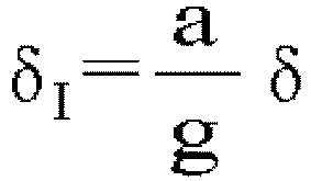
where δI denotes the pixel size of the reproduced image, g denotes a first separation distance between the pattern film and the reproduction lens array, a denotes the second separation distance between the reproduction lens array and the center of the reproduced stereoscopic image, and δ denotes the size of a unit pixel of the patterned image. - For example, a first resolution of the reproduced stereoscopic image may be inversely proportional to the pixel size of the reproduced image.
- For example, a second resolution of the patterned image may be as follows:

where RD denotes the second resolution, RI denotes a first resolution of the reproduced stereoscopic image, Δz denotes a depth of the reproduced stereoscopic image, and ψ denotes a view angle of the reproduced stereoscopic image. - For example, the size of a unit lens constituting the reproduction lens array may be less than 1 mm to 2 mm or may be 5 mm to 10 mm. A unit lens constituting the reproduction lens array may include a fly-eye lens.
- According to another embodiment, provided herein is a lamp used in a vehicle, including the integral image processing apparatus.
- According to the present invention, an integral image processing apparatus includes an entire picked-up elemental image in a pattern film or engraves a pattern of a patterned image on the back of a reproduction lens array, so that the volume of the integral image processing apparatus can be reduced. If the integral image processing apparatus is applied to a lamp of a vehicle such as a tail lamp, a stereoscopic image is provided to other vehicles behind the vehicle to provide high visibility and sophisticated design.
-
-
FIG. 1 is a block diagram of an integral image processing apparatus according to an embodiment. -
FIG. 2 is a view conceptually illustrating an embodiment of a pickup unit illustrated inFIG. 1 . -
FIGS. 3a to 3d are views illustrating a patterned image and a stereoscopic image. -
FIG. 4 is a view conceptually illustrating an embodiment of a display unit illustrated inFIG. 1 . -
FIG. 5 is a view conceptually illustrating another embodiment of the display unit illustrated inFIG. 1 . -
FIGS. 6A to 6C illustrate various shapes of a reproduction lens array illustrated inFIGS. 4 and5 . -
FIG. 7 exemplarily illustrates a pattern of a patterned image transferred on a reproduction lens array. -
FIG. 8 is a view illustrating an example applied to an integral image processing apparatus according to an embodiment. - Hereinafter, embodiments of the present invention will be described in detail with reference to the attached drawings to aid in understanding of the present invention. However, embodiments according to the present invention can be modified in various ways and the scope of the present invention should not be interpreted as being limited to the following embodiments. Embodiments of the present invention are provided to fully describe the present invention to those having ordinary knowledge in the art to which the present invention pertains.
- In description of the embodiments, it will be understood that, when an element is referred to as being formed "on" or "under" another element, it can be directly "on" or "under" the other element or be indirectly formed with intervening elements therebetween.
- It will also be understood that, when an element is referred to as being "on" or "under," "under the element" as well as "on the element" can be included based on the element.
- As used herein, relational terms, such as "on"/"upper part"/"above", "under"/"lower part"/"below," and the like, are used solely to distinguish one entity or element from another entity or element without necessarily requiring or implying any physical or logical relationship or order between such entities or elements.
- Hereinafter, an integral
image processing apparatus 100 according to an embodiment will be described with reference to the attached drawings. For convenience, theimaging processing apparatus 100 using the Cartesian coordinate system (x-axis, y-axis, and z-axis) is described. However, it is apparent that theimage processing apparatus 100 can be described using other coordinate systems. Although the x-axis, the y-axis, and the x-axis are orthogonal according to the Cartesian coordinate system, embodiments are not limited thereto. In other words, the x-axis, the y-axis, and z-axis may not be orthogonal and may cross. -
FIG. 1 is a block diagram of the integralimage processing apparatus 100 according to an embodiment. The integral image processing apparatus may include apickup unit 110 and a display unit (or a reproduction unit) 120. - Referring to
FIG. 1 , thepickup unit 110 generates an entire elemental image for a 3D object OB and patterns the generated entire elemental image. Therefore, the patterned image generated from thepickup unit 110 is transmitted to thedisplay unit 120 in various manners which will be described later. Herein, the entire elemental image may consist of a plurality of individual elemental images. - Hereinafter, an embodiment for generating the patterned image for the 3D object OB by the
pickup unit 110 will be described. -
FIG. 2 is a view conceptually illustrating anembodiment 110A of thepickup unit 110 illustrated inFIG. 1 . AlthoughFIG. 2 shows a 2D plane of the y-axis and the z-axis, a 3D object OB is represented as a perspective view to aid in understanding of the embodiment. - According to an embodiment, the
pickup unit 110A may include a lens array (hereinafter, referred to as a "pickup lens array") 112 and apattern film 114. - The
pickup lens array 112 causes a plurality of rays generated from a 3D object (or an object) OB to pass therethrough. - To this end, the
pickup lens array 112 may include a plurality of individual lenses. A plurality of individual elemental images of the 3D object OB seen from various directions in space is generated by the plural individual lenses. An individual elemental image is a 2D basic image for enabling a user to see the 3D object OB. The plural individual elemental images may have a uniform size. - Next, the entire elemental image consisting of a plurality of individual elemental images, each of which passes through each individual lens of the
pickup lens array 112, may reach thepattern film 114 and may be engraved as a pattern of the patterned image. For example, thepattern film 114 may be polyethylene terephthalate (PET) but embodiments are not limited thereto. - In a general integral image processing apparatus, the pickup unit stores the entire elemental image in an imaging device. However, in the integral image processing apparatus according to an embodiment, the entire elemental image may be stored in the
pattern film 114 in the form of a pattern (i.e., may be engraved). In this way, the patterned image for the 3D object OB may be physically generated. - According to another embodiment, the
pickup unit 110 may model the 3D object OB and estimate an illuminance value of a pixel included in each of the plural individual elemental images after the modeled object passes through the pickup lens array, thereby generating data for the illuminance value with respect to coordinates of each pixel as the patterned image. For example, the entire elemental image may be generated by computer-generated integral imaging (CGII) using computer graphics. That is, the data for the illuminance value with respect to coordinates of the entire elemental image consisting of the plural individual elemental images for the 3D object OB may be generated as the patterned image by a computer algorithm. Thus, the patterned image for the 3D object OB may be programmatically generated. - According to a further embodiment, the patterned image may be generated in various ways without being limited to the above-described two embodiments. That is, the integral
image processing apparatus 100 according to an embodiment may not include thepickup unit 110. In this case, a predefined patterned image may be provided to thedisplay unit 120. - The entire elemental image may be a video image (or active image) for the 3D object OB or may be a still image. That is, according to an application of the integral
image processing apparatus 100 of an embodiment, various still images may be generated as the patterned image. -
FIGS. 3a to 3d are views illustrating a patterned image and a stereoscopic image.FIG. 3a is a front view exemplarily illustrating a 3D object OB,FIG. 3b is a perspective view exemplarily illustrating the 3D object OB illustrated inFIG. 3a .FIG. 3c exemplarily illustrates a patterned image andFIG. 3d exemplarily illustrates a stereoscopic image. - In
FIG. 2 , although the 3D object OB has a cylindrical shape, embodiments are not limited thereto. For example, as illustrated inFIG. 3b , if the 3D object OB has the shape of three rings, the patterned image may have a shape illustrated inFIG. 3c . - As described above, a pattern of the patterned image illustrated in
FIG. 3c may be engraved on thepattern film 114 or may be generated as data by a program. - Meanwhile, referring back to
FIG. 1 , thedisplay unit 120 may reproduce the entire elemental image for the 3D object OB as a 3D image. That is, thedisplay unit 120 may reproduce the 3D stereoscopic image from the patterned image generated from thepickup unit 110 illustrated inFIG. 1 or from a predefined patterned image. If the patterned image is as illustrated inFIG. 3c and the 3D object OB is as illustrated inFIGS. 3a and3b , the stereoscopic image illustrated inFIG. 3d may be reproduced by thedisplay unit 120. -
FIG. 4 is a view conceptually illustrating anembodiment 120A of thedisplay unit 120 illustrated inFIG. 1 . - According to an embodiment, as illustrated in
FIG. 4 , thedisplay unit 120A may include alight source 122, apattern film 124, and a lens array (hereinafter, referred to as a "reproduction lens array") 126. - The
light source 122 emits light towards thepattern film 124. Thelight source 122 may emit scattered light but embodiments are not limited to the types of light emitted from thelight source 122. For example, a backlight unit (BLU) may be used as thelight source 122 but embodiments are not limited to the types oflight source 122. - The
pattern film 124 illustrated inFIG. 4 may be thepattern film 114 illustrated inFIG. 2 . As described above with reference toFIG. 2 , if the entire elemental image for the 3D object OB is patterned and a pattern of the patterned image is engraved on thepattern film 114, thepattern film 114 may be used in thedisplay unit 120A. Thepattern film 124 illustrated inFIG. 4 may be disposed between thelight source 122 and thereproduction lens array 126 but embodiments are not limited thereto. - In addition, a plurality of individual elemental images included in the patterned image may be integrated so as to be reproduced as a stereoscopic image RI. That is, individual elemental images of the 3D object OB constituting the entire elemental image included in the patterned image are integrated while passing through the
reproduction lens array 126, thereby being reproduced as the stereoscopic image. To this end, light may be emitted from thelight source 122. - If the pattern of the patterned image is engraved in the
pattern film 114 as illustrated inFIG. 2 , thereproduction lens array 126 illustrated inFIG. 4 and thepickup lens array 112 illustrated inFIG. 2 may have the same characteristics. For example, the pickup andreproduction lens arrays FIGS. 2 and4 may have the following similar characteristics. - A first separation distance g between the
pattern film 124 and thereproduction lens array 126 illustrated inFIG. 4 may be equal to a separation distance g' between thepickup lens array 112 and thepattern film 114 illustrated inFIG. 2 . Herein, the first separation distance g may correspond to a separation distance to thelens array 126 from an outer plane SO of thepattern film 124 facing thereproduction lens array 126. - A second separation distance a between the
reproduction lens array 126 illustrated inFIG. 4 and a center depth plane (CDP) (or a reference depth plane) of a reproduced stereoscopic image RI may be equal to a separation distance a' between the 3D object OB and thepickup lens array 112 illustrated inFIG. 2 . - The first separation distance g illustrated in
FIG. 4 may be determined as indicated byEquation 1 according to a resolution RI of the reproduced stereoscopic image RI.
- Herein, referring to
FIG. 4 , δ denotes the size of a unit pixel of a patterned image having a pattern engraved on thepattern film 124. - The first separation distance g and the second separation distance a illustrated in
FIG. 4 may be determined as indicated byEquation 2 according to the first resolution R1 of the reproduced stereoscopic image and a second resolution RD of a patterned image having a pattern engraved on thepattern film 124.
- Referring to
Equations 
- Referring to
Equation 2, it can be appreciated that, when the second resolution RD is fixed, the first resolution RI is adjusted by adjusting the first and second separation distances g and a. - The number of lenses included in the
reproduction lens array 126 illustrated inFIG. 4 may be equal to the number of lenses included in thepickup lens array 112 illustrated inFIG. 2 . - A unit lens constituting each of the
reproduction lens array 126 illustrated inFIG. 4 and thepickup lens array 112 illustrated inFIG. 2 may be a fly-eye lens but embodiments are not limited to the types of the unit lens. - A size p of a unit lens included in the
reproduction lens array 126 illustrated inFIG. 4 may be equal to a size p' of a unit lens included in thepickup lens array 112 included inFIG. 2 . For example, if the stereoscopic perception (or depth perception) of the reproduced stereoscopic image RI has priority over the first resolution RI of the reproduced stereoscopic image RI, the size p of each unit lens constituting thereproduction lens array 126 may be 2 mm or less but embodiments are not limited thereto. - Alternatively, if the first resolution RI of the reproduced stereoscopic image RI has priority over the stereoscopic perception of the reproduced stereoscopic image RI, the size p of each unit lens constituting the
reproduction lens array 126 may be 5 mm or more but embodiments are not limited thereto. - If the integral image processing apparatus according to this embodiment is applied to a vehicle tail lamp which will be described with reference to
FIG. 8 , the height of an individual integral image processing apparatus may be limited to a maximum of 15 mm although it may be different according to the construction of the tail lamp. In this case, if the size p of each unit lens is less than 1 mm, a view angle is remarkably reduced to 15 degrees or less and, if the size p of each unit lens is greater than 10 mm, it is difficult to secure the depth perception of 30 mm or more. Accordingly, if stereoscopic perception takes priority over the first resolution, the size of the unit lens may have a range of 1 mm to 2 mm and, if the first resolution takes priority over the stereoscopic perception, the size of the unit lens may have a range of 5 mm to 10 mm. However, embodiments are not limited thereto. - A view angle ψ of the reproduced stereoscopic image RI may be determined as indicated by
Equation 4.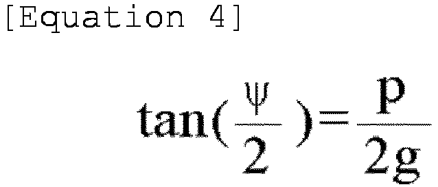
- Herein, referring to
Equation 4, it can be appreciated that the view angle ψ can be adjusted according to the size p of the unit lens included in thereproduction lens array 126 and the first separation distance g. - A depth Δz of the reproduced image RI may be determined as indicated by Equation 5.

- Herein, δI denotes a pixel size of the reproduced stereoscopic image RI and may be represented by Equation 6.
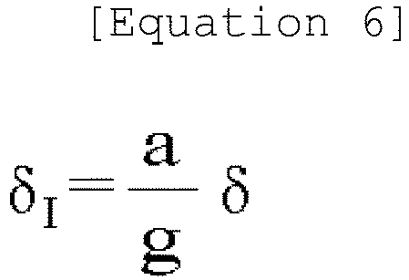
- Referring to Equations 3, 5, and 6, it can be appreciated that the depth Δz of the reproduced image can be adjusted by adjusting the size p of the unit lens and the first and second separation distances g and a in a state in which the second resolution RD is fixed.
- If Equation 7 indicated below is substituted into Equation 5 and
Equations Equation 8.

- Referring to
FIG. 4 , the depth Δz of the reproduced image RI may be defined by a first marginal depth plane MDP1 and a second marginal depth plane MDP2. Therefore, the depth Δz of the reproduced image RI expressed as indicated by Equation 5 may be an interval between the first marginal depth plane MDP1 and the second marginal depth plane MDP2 in the z-axis direction. As the depth Δz of the reproduced image RI increases, the stereoscopic sense of the reproduced image RI may also increase. - In addition, "a CDP of a stereoscopic image RI" which is mentioned when defining the second separation distance a may be any one point on a CDP located at the middle between the first marginal depth plane MDP1 and the second marginal depth plane MDP2.
-
FIG. 5 is a view conceptually illustrating anotherembodiment 120B of thedisplay unit 120 illustrated inFIG. 1 . - According to another embodiment, the
display unit 120B may include alight source 122 and areproduction lens array 126 as illustrated inFIG. 5 - Referring to
FIG. 5 , thereproduction lens array 126 may include a first plane S1 and a second plane S2. The first plane S1 corresponds to the back surface of thereproduction lens array 126 facing thelight source 122 and the second plane S2 corresponds to the front surface of thereproduction lens array 126 facing a reproduced stereoscopic image RI from the opposite side of the first plane S1. - The
display unit 120B illustrated inFIG. 5 according to another embodiment does not include thepattern film 124. In this case, apattern 125 of a patterned image corresponding to an entire elemental image for a 3D object OB may be transferred and engraved on the first plane S1 of thereproduction lens array 126. In this way, except that thepattern 125 of the patterned image is transferred on the first plane S1 of thereproduction lens array 126 instead of being engraved on thepattern film 124, since thedisplay unit 120B illustratedFIG. 5 is the same as thedisplay unit 120A illustrated inFIG. 4 , a repetitive description will be omitted. -
FIGS. 6A to 6C illustrate various shapes of thereproduction lens array 126 illustrated inFIGS. 4 and5 . Based on thereproduction lens array 126 illustrated inFIGS. 4 and5 ,FIG. 6A is a right side view of thereproduction lens array 126,FIG. 6B is a front view of thereproduction lens array 126, and FIG. 6C is a left side view of thereproduction lens array 126. -
FIG. 7 exemplarily illustrates a pattern of a patterned image transferred on thereproduction lens array 126. - If the patterned image for the 3D object illustrated in
FIGS. 3a and3b is given as illustrated inFIG. 3c , the pattern of the patterned image as illustrated inFIG. 7 may be engraved on the first plane S1 of thereproduction lens array 126 illustrated in FIG. 6c. - According to an embodiment, the pattern of the patterned image may be engraved on the first plane S1 of the
reproduction lens array 126 in the form of roughness or intaglio. - Although the
light source 122 is disposed in contact with thepattern 125 of the patterned image engraved on the first plane S1 of thereproduction lens array 126 as illustrated inFIG. 5 , embodiments are not limited thereto. That is, according to another embodiment, thelight source 122 may be disposed separately from thepattern 125 of the patterned image in the z-axis direction. - As described above, in the
display unit 120A illustrated inFIG. 2 , the pattern of the patterned image is engraved on thepattern film 124, whereas, in thedisplay unit 120B illustrated inFIG. 4 , thepattern 125 of the patterned image is engraved on the first plane S1 of thereproduction lens array 126. - Meanwhile, according to an embodiment, the first separation distance g, the second separation distance a, the view angle ψ, a maximum value max(Δz) of the depth of the reproduced image, and the pixel size δI of the reproduced image RI may have various values as shown in Table 1 according to the above-described equations.
[Table 1] Classification g (mm) a (mm) ψ (°) max (Δz) (mm) δI (mm) Description CASE 1 11 110 25.6 132 3 f=10 14 35 20.2 10.5 0.75 p=5 20 20 14.3 2.4 0.3 δ=0.3 CASE 211 110 48.9 66 3 f=10 14 35 39.3 5.25 0.75 p=10 20 20 28 1.2 0.3 δ=0.3 CASE 3 6 30 45.2 18 1.5 f=5 8 13.3 34.7 2.7 0.5 p=5 10 10 28 1.2 0.3 δ=0.3 CASE 411 110 25.6 440 10 f=10 14 35 20.2 35 2.5 p=5 20 20 14.3 8 1 δ=1 - Referring to Table 1, if the size p of each of a plurality of unit lenses constituting the
reproduction lens array 126 is increased from 5 mm ofCASE 1 to 10 mm ofCASE 2, it can be appreciated that the view angle ψ becomes wider but the stereoscopic sense (max(Δz)) of the reproduced image RI is lowered. - In addition, if a focus distance f of the
reproduction lens array 126 is decreased from 10 mm ofCASE 1 to 5 mm of CASE 3, it can be appreciated that the view angle ψ is increased, similar toCASE 2, and the stereoscopic sense (max(Δz)) is lower than that ofCASE 2 but a width g in the z-axis direction of thedisplay unit 120 becomes thinner. Herein, the focus distance f has a relationship indicated in Equation 9.
- If the size δ of a pixel included in a patterned image is increased from 0.3 mm of
CASE 1 to 1 mm ofCASE 4, it can be appreciated that the view angle ψ is the same as that ofCASE 1 and the stereoscopic perception (max(Δz)) is increased aboveCASE - As described with reference to Table 1, it can be appreciated that the view angle ψ and the stereoscopic perception (max(Δz)) can be adjusted by adjusting the focus distance f of the
reproduction lens array 126, the size p of each of a plurality of unit lenses, and the size δ of a pixel included in an image pattern. Accordingly, the view angle ψ and the stereoscopic perception (max(Δz)) can be satisfied in fields to which the above-described integralimage processing apparatus 100 is applied by adjusting the focus distance f of thereproduction lens array 126, the size p of each of a plurality of unit lenses, and the size δ of a pixel included in a patterned image. - The integral image processing apparatus according to the above-described embodiment may be applied to various fields. Accordingly, if the integral
image processing apparatus 100 includes only thedisplay unit pickup unit 110, thedisplay unit display units -
FIG. 8 is a view illustrating an example applied to the integralimage processing apparatus 100 according to an embodiment. - The
display unit 120B of the integralimage processing apparatus 100 illustrated inFIG. 5 according to the above-described embodiment may be applied to a tail lamp of avehicle 200 as illustrated inFIG. 8 . Although not illustrated, thedisplay unit 120A illustrated inFIG. 4 , instead of thedisplay unit 120B illustrated inFIG. 5 , may be applied to the tail lamp of thevehicle 200. - In this case, the stereoscopic image RI may be reproduced as illustrated in
FIG. 3d even in a space separated from the tail of thevehicle 200. - If the integral
image processing apparatus 100 according to the above-described embodiment is applied to a tail lamp of the vehicle as illustrated inFIG. 8 , high visibility can be provided by providing a stereoscopic image to other vehicles behind thevehicle 200 and a sophisticated design can be provided. - While the present disclosure has been particularly shown and described with reference to exemplary embodiments thereof, these embodiments are only proposed for illustrative purposes and do not restrict the present disclosure, and it will be apparent to those skilled in the art that various changes in form and detail may be made without departing from the essential characteristics of the embodiments set forth herein. For example, respective configurations set forth in the embodiments may be modified and applied. Further, differences in such modifications and applications should be construed as falling within the scope of the present disclosure as defined by the appended claims.
- The integral image processing apparatus according to an embodiment includes an entire picked-up elemental image in a pattern film or a pattern of a patterned image is engraved on the back of the reproduction lens array so that the volume of the integral image processing apparatus can be reduced because a display panel is not needed in the display panel. If the integral image processing apparatus is applied to a tail lamp of a vehicle, high visibility can be provided by providing a stereoscopic image to other vehicles behind the vehicle and a sophisticated design can be provided.
Claims (20)
- An integral image processing apparatus comprising a display unit configured to reproduce an entire elemental image for a 3-dimensional (3D) object as a 3D image, wherein the display unit comprises:a light source; anda reproduction lens array for integrating a plurality of individual elemental images, which are included in a patterned image obtained by patterning the entire elemental image and constitute the entire elemental image, and reproducing the individual elemental images as a stereoscopic image.
- The integral image processing apparatus according to claim 1, wherein the display unit includes a pattern of the patterned image and further comprises a pattern film disposed between the light source and the reproduction lens array.
- The integral image processing apparatus according to claim 1, wherein the reproduction lens array includes:a first plane facing the light source; anda second plane facing the reproduced stereoscopic image from the opposite side of the first plane.
- The integral image processing apparatus according to claim 3, wherein the pattern of the patterned image is transferred to the first plane and then is engraved on the first plane.
- The integral image processing apparatus according to claim 4, wherein the pattern of the patterned image is engraved on the first plane of the reproduction lens array in the form of roughness.
- The integral image processing apparatus according to claim 4, wherein the pattern of the patterned image is engraved on the first plane of the reproduction lens array in the form of intaglio.
- The integral image processing apparatus according to claim 2, further comprising a pickup unit configured to generate the patterned image.
- The integral image processing apparatus according to claim 7, wherein the pickup unit includes a pickup lens array configured to cause a plurality of rays emitted from the 3D object to pass therethrough to generate the plural individual elemental images, and the entire elemental image consisting of the plural individual elemental images passing through the pickup lens array is engraved on the pattern film as the pattern of the patterned image.
- The integral image processing apparatus according to claim 8, wherein the pickup lens array has the same characteristics as the reproduction lens array.
- The integral image processing apparatus according to claim 7, wherein the pickup unit models the 3D object, estimates an illuminance value of a pixel included in each of the plural individual elemental images after the modeled result passes through a pickup lens array, and generates data for an illuminance value with respect to coordinates of each pixel as the patterned image.
- The integral image processing apparatus according to claim 2, wherein a first separation distance between the pattern film and the reproduction lens array is determined as follows according to a first resolution of the reproduced stereoscopic image:

- The integral image processing apparatus according to claim 2, wherein a first separation distance between the pattern film and the reproduction lens array and a second separation distance between the reproduction lens array and a center of the reproduced stereoscopic image are determined as follows according to a first resolution of the reproduced stereoscopic image and a second resolution of the patterned image:

- The integral image processing apparatus according to claim 2, wherein a view angle of the reproduced stereoscopic image is determined as follows:

- The integral image processing apparatus according to claim 2, wherein a depth of the reproduced stereoscopic image is as follows:

- The integral image processing apparatus according to claim 14, wherein the pixel size of the reproduced image is as follows:

- The integral image processing apparatus according to claim 14, wherein a first resolution of the reproduced stereoscopic image is inversely proportional to the pixel size of the reproduced image.
- The integral image processing apparatus according to claim 2, wherein a second resolution of the patterned image is as follows:

- The integral image processing apparatus according to claim 4, wherein the size of a unit lens constituting the reproduction lens array is less than 1 mm to 2 mm or is 5 mm to 10 mm.
- The integral image processing apparatus according to claim 1, wherein a unit lens constituting the reproduction lens array includes a fly-eye lens.
- A lamp used in a vehicle, comprising the integral image processing apparatus of claim 1.
Applications Claiming Priority (2)
| Application Number | Priority Date | Filing Date | Title |
|---|---|---|---|
| KR1020150136821A KR102486430B1 (en) | 2015-09-25 | 2015-09-25 | Imaging processing apparatus |
| PCT/KR2016/010754 WO2017052325A1 (en) | 2015-09-25 | 2016-09-26 | Integral image processing device and vehicular lamp using same |
Publications (3)
| Publication Number | Publication Date |
|---|---|
| EP3355577A1 true EP3355577A1 (en) | 2018-08-01 |
| EP3355577A4 EP3355577A4 (en) | 2018-09-26 |
| EP3355577B1 EP3355577B1 (en) | 2020-06-03 |
Family
ID=58386609
Family Applications (1)
| Application Number | Title | Priority Date | Filing Date |
|---|---|---|---|
| EP16849050.6A Active EP3355577B1 (en) | 2015-09-25 | 2016-09-26 | Integral image processing device |
Country Status (5)
| Country | Link |
|---|---|
| US (1) | US11275255B2 (en) |
| EP (1) | EP3355577B1 (en) |
| KR (1) | KR102486430B1 (en) |
| CN (1) | CN108141580B (en) |
| WO (1) | WO2017052325A1 (en) |
Families Citing this family (6)
| Publication number | Priority date | Publication date | Assignee | Title |
|---|---|---|---|---|
| DE102017108498A1 (en) * | 2017-04-21 | 2018-10-25 | HELLA GmbH & Co. KGaA | Lighting device for vehicles |
| US10851962B2 (en) | 2017-12-12 | 2020-12-01 | Flex-N-Gate Advanced Product Development, Llc | Backlit 3D lamp |
| CN108833894A (en) * | 2018-06-09 | 2018-11-16 | 成都工业学院 | An integrated imaging 3D display method with adjustable viewing parameters |
| CN108881881B (en) * | 2018-08-03 | 2020-10-09 | 北京航空航天大学 | Self-adaptive micro-image array generation method for 3D display of integrated imaging desktop |
| TWI772014B (en) * | 2021-05-05 | 2022-07-21 | 幻景啟動股份有限公司 | Stereoscopic image display device capable of reducing grid effect |
| CN113759650A (en) * | 2021-07-14 | 2021-12-07 | 东风汽车集团股份有限公司 | Vehicle carpet lamp, vehicle carpet lamp system component and design method |
Family Cites Families (24)
| Publication number | Priority date | Publication date | Assignee | Title |
|---|---|---|---|---|
| CN2609102Y (en) * | 2003-04-15 | 2004-03-31 | 陈震 | Pattern stand |
| WO2006093365A1 (en) * | 2005-03-02 | 2006-09-08 | Seoul National University Industry Foundation | Three-dimensional/ two-dimensional convertible display device |
| EP1893074B2 (en) * | 2005-05-18 | 2017-06-14 | Visual Physics, LLC | Image presentation and micro-optic security system |
| JP2008026654A (en) * | 2006-07-21 | 2008-02-07 | Hitachi Displays Ltd | 3D display device |
| JP2008052010A (en) | 2006-08-24 | 2008-03-06 | Noriji Ooishi | Stereoscopic image display device and photographing device |
| KR100910642B1 (en) | 2007-07-27 | 2009-08-05 | 광운대학교 산학협력단 | 3D integrated image restoration method and apparatus for images acquired by holography |
| TWI387316B (en) * | 2008-11-18 | 2013-02-21 | 財團法人工業技術研究院 | Stereoscopic image display device and stereoscopic image display method |
| WO2010072065A1 (en) | 2008-12-25 | 2010-07-01 | 深圳市泛彩溢实业有限公司 | Hologram three-dimensional image information collecting device and method, reproduction device and method |
| WO2010136921A2 (en) * | 2009-05-28 | 2010-12-02 | Koninklijke Philips Electronics N.V. | Autostereoscopic display device |
| WO2010143639A1 (en) * | 2009-06-12 | 2010-12-16 | 旭硝子株式会社 | Projection display device |
| WO2012015106A1 (en) * | 2010-07-24 | 2012-02-02 | Chung Hyun In | Interlaced pattern structure and stereoscopic image apparatus employing integral photography technique |
| KR20120090507A (en) | 2011-02-08 | 2012-08-17 | 엘지디스플레이 주식회사 | Integral imaging type stereoscopic image display device |
| KR20120093693A (en) | 2011-02-15 | 2012-08-23 | 엘지디스플레이 주식회사 | Stereoscopic 3d display device and method of driving the same |
| WO2012144836A2 (en) * | 2011-04-19 | 2012-10-26 | 전자부품연구원 | 3-dimensional image display and recording device |
| CN102209254B (en) | 2011-05-30 | 2012-12-05 | 四川大学 | One-dimensional integrated imaging method and device |
| KR20130055460A (en) | 2011-11-18 | 2013-05-28 | 인포뱅크 주식회사 | Display apparatus for vehicle and recording medium |
| US9057880B2 (en) * | 2011-11-30 | 2015-06-16 | Reald Inc. | Laser beam scanned display apparatus and method thereof |
| KR101881163B1 (en) | 2012-03-20 | 2018-07-23 | 엘지디스플레이 주식회사 | Integral image system and driving method of the same |
| CN103342060B (en) | 2013-06-18 | 2016-01-20 | 坤达国际有限公司 | A kind of three-dimensional image printed matter and three-dimensional image printing process |
| CN203442674U (en) * | 2013-07-19 | 2014-02-19 | 汕头市晟琪塑胶制品有限公司 | Lampshade |
| KR101620147B1 (en) * | 2013-12-18 | 2016-05-23 | 현대자동차주식회사 | Light source module of lamp for vehicle |
| WO2015197654A1 (en) * | 2014-06-26 | 2015-12-30 | Koninklijke Philips N.V. | Optical arrangement, lighting device and illumination method |
| KR101472921B1 (en) | 2014-08-11 | 2014-12-17 | 골드맥스그룹 주식회사 | The three-dimentional label by using the fine pattern and the microlens |
| KR20160040384A (en) * | 2014-10-02 | 2016-04-14 | 삼성전자주식회사 | Light emitting device |
-
2015
- 2015-09-25 KR KR1020150136821A patent/KR102486430B1/en active Active
-
2016
- 2016-09-26 EP EP16849050.6A patent/EP3355577B1/en active Active
- 2016-09-26 US US15/762,353 patent/US11275255B2/en active Active
- 2016-09-26 CN CN201680055720.5A patent/CN108141580B/en active Active
- 2016-09-26 WO PCT/KR2016/010754 patent/WO2017052325A1/en not_active Ceased
Also Published As
| Publication number | Publication date |
|---|---|
| US11275255B2 (en) | 2022-03-15 |
| US20180239159A1 (en) | 2018-08-23 |
| WO2017052325A1 (en) | 2017-03-30 |
| EP3355577A4 (en) | 2018-09-26 |
| KR102486430B1 (en) | 2023-01-10 |
| KR20170037346A (en) | 2017-04-04 |
| CN108141580A (en) | 2018-06-08 |
| EP3355577B1 (en) | 2020-06-03 |
| CN108141580B (en) | 2021-02-05 |
Similar Documents
| Publication | Publication Date | Title |
|---|---|---|
| EP3355577B1 (en) | Integral image processing device | |
| JP6308513B2 (en) | Stereoscopic image display apparatus, image processing apparatus, and stereoscopic image processing method | |
| US7719621B2 (en) | Image display device and method having image control unit preventing light source unit from outputting an image when observer is outside of predefined normal viewing area | |
| JP6516234B2 (en) | Stereoscopic display | |
| US12052406B2 (en) | Display apparatus and operating method of the same | |
| US9494798B2 (en) | Image display apparatus and image display method | |
| JP4881871B2 (en) | 3D display device | |
| TW201624058A (en) | Wide angle stereoscopic image display method, stereoscopic image display device and operation method thereof | |
| JP7335233B2 (en) | A system and method for displaying two-viewpoint autostereoscopic images on an N-viewpoint autostereoscopic display screen and a method for controlling the display on such a display screen | |
| US20180139437A1 (en) | Method and apparatus for correcting distortion | |
| KR101741227B1 (en) | Auto stereoscopic image display device | |
| KR101567002B1 (en) | Computer graphics based stereo floting integral imaging creation system | |
| JP7127415B2 (en) | virtual image display | |
| KR101883883B1 (en) | method for glass-free hologram display without flipping images | |
| KR101093929B1 (en) | Method and system for displaying 3D image using depth map | |
| KR100893381B1 (en) | Real time stereoscopic image generation method | |
| US12568197B2 (en) | Light field display apparatus | |
| CN115220240B (en) | Generating method and display system of stereoscopic image data adapted to eye position | |
| KR101502407B1 (en) | Stereo integral imaging display system | |
| WO2025047846A1 (en) | Electronic mirror system and electronic mirror display method | |
| KR101555974B1 (en) | Table-top type three dimensional display system using lens array | |
| KARAJEH | Intermediate view reconstruction for multiscopic 3D display |
Legal Events
| Date | Code | Title | Description |
|---|---|---|---|
| STAA | Information on the status of an ep patent application or granted ep patent |
Free format text: STATUS: THE INTERNATIONAL PUBLICATION HAS BEEN MADE |
|
| PUAI | Public reference made under article 153(3) epc to a published international application that has entered the european phase |
Free format text: ORIGINAL CODE: 0009012 |
|
| STAA | Information on the status of an ep patent application or granted ep patent |
Free format text: STATUS: REQUEST FOR EXAMINATION WAS MADE |
|
| 17P | Request for examination filed |
Effective date: 20180424 |
|
| AK | Designated contracting states |
Kind code of ref document: A1 Designated state(s): AL AT BE BG CH CY CZ DE DK EE ES FI FR GB GR HR HU IE IS IT LI LT LU LV MC MK MT NL NO PL PT RO RS SE SI SK SM TR |
|
| AX | Request for extension of the european patent |
Extension state: BA ME |
|
| REG | Reference to a national code |
Ref country code: DE Ref legal event code: R079 Ref document number: 602016037683 Country of ref document: DE Free format text: PREVIOUS MAIN CLASS: H04N0013040000 Ipc: H04N0013000000 |
|
| RIC1 | Information provided on ipc code assigned before grant |
Ipc: H04N 13/30 20180101ALI20180815BHEP Ipc: H04N 13/307 20180101ALI20180815BHEP Ipc: G02B 27/22 20180101ALI20180815BHEP Ipc: H04N 13/00 20180101AFI20180815BHEP |
|
| A4 | Supplementary search report drawn up and despatched |
Effective date: 20180823 |
|
| DAV | Request for validation of the european patent (deleted) | ||
| DAX | Request for extension of the european patent (deleted) | ||
| STAA | Information on the status of an ep patent application or granted ep patent |
Free format text: STATUS: EXAMINATION IS IN PROGRESS |
|
| 17Q | First examination report despatched |
Effective date: 20190508 |
|
| GRAP | Despatch of communication of intention to grant a patent |
Free format text: ORIGINAL CODE: EPIDOSNIGR1 |
|
| STAA | Information on the status of an ep patent application or granted ep patent |
Free format text: STATUS: GRANT OF PATENT IS INTENDED |
|
| INTG | Intention to grant announced |
Effective date: 20200108 |
|
| GRAS | Grant fee paid |
Free format text: ORIGINAL CODE: EPIDOSNIGR3 |
|
| GRAA | (expected) grant |
Free format text: ORIGINAL CODE: 0009210 |
|
| STAA | Information on the status of an ep patent application or granted ep patent |
Free format text: STATUS: THE PATENT HAS BEEN GRANTED |
|
| AK | Designated contracting states |
Kind code of ref document: B1 Designated state(s): AL AT BE BG CH CY CZ DE DK EE ES FI FR GB GR HR HU IE IS IT LI LT LU LV MC MK MT NL NO PL PT RO RS SE SI SK SM TR |
|
| REG | Reference to a national code |
Ref country code: GB Ref legal event code: FG4D |
|
| REG | Reference to a national code |
Ref country code: CH Ref legal event code: EP Ref country code: AT Ref legal event code: REF Ref document number: 1278294 Country of ref document: AT Kind code of ref document: T Effective date: 20200615 |
|
| REG | Reference to a national code |
Ref country code: DE Ref legal event code: R096 Ref document number: 602016037683 Country of ref document: DE |
|
| REG | Reference to a national code |
Ref country code: LT Ref legal event code: MG4D |
|
| PG25 | Lapsed in a contracting state [announced via postgrant information from national office to epo] |
Ref country code: FI Free format text: LAPSE BECAUSE OF FAILURE TO SUBMIT A TRANSLATION OF THE DESCRIPTION OR TO PAY THE FEE WITHIN THE PRESCRIBED TIME-LIMIT Effective date: 20200603 Ref country code: LT Free format text: LAPSE BECAUSE OF FAILURE TO SUBMIT A TRANSLATION OF THE DESCRIPTION OR TO PAY THE FEE WITHIN THE PRESCRIBED TIME-LIMIT Effective date: 20200603 Ref country code: SE Free format text: LAPSE BECAUSE OF FAILURE TO SUBMIT A TRANSLATION OF THE DESCRIPTION OR TO PAY THE FEE WITHIN THE PRESCRIBED TIME-LIMIT Effective date: 20200603 Ref country code: NO Free format text: LAPSE BECAUSE OF FAILURE TO SUBMIT A TRANSLATION OF THE DESCRIPTION OR TO PAY THE FEE WITHIN THE PRESCRIBED TIME-LIMIT Effective date: 20200903 Ref country code: GR Free format text: LAPSE BECAUSE OF FAILURE TO SUBMIT A TRANSLATION OF THE DESCRIPTION OR TO PAY THE FEE WITHIN THE PRESCRIBED TIME-LIMIT Effective date: 20200904 |
|
| REG | Reference to a national code |
Ref country code: NL Ref legal event code: MP Effective date: 20200603 |
|
| PG25 | Lapsed in a contracting state [announced via postgrant information from national office to epo] |
Ref country code: BG Free format text: LAPSE BECAUSE OF FAILURE TO SUBMIT A TRANSLATION OF THE DESCRIPTION OR TO PAY THE FEE WITHIN THE PRESCRIBED TIME-LIMIT Effective date: 20200903 Ref country code: RS Free format text: LAPSE BECAUSE OF FAILURE TO SUBMIT A TRANSLATION OF THE DESCRIPTION OR TO PAY THE FEE WITHIN THE PRESCRIBED TIME-LIMIT Effective date: 20200603 Ref country code: LV Free format text: LAPSE BECAUSE OF FAILURE TO SUBMIT A TRANSLATION OF THE DESCRIPTION OR TO PAY THE FEE WITHIN THE PRESCRIBED TIME-LIMIT Effective date: 20200603 Ref country code: HR Free format text: LAPSE BECAUSE OF FAILURE TO SUBMIT A TRANSLATION OF THE DESCRIPTION OR TO PAY THE FEE WITHIN THE PRESCRIBED TIME-LIMIT Effective date: 20200603 |
|
| REG | Reference to a national code |
Ref country code: AT Ref legal event code: MK05 Ref document number: 1278294 Country of ref document: AT Kind code of ref document: T Effective date: 20200603 |
|
| PG25 | Lapsed in a contracting state [announced via postgrant information from national office to epo] |
Ref country code: AL Free format text: LAPSE BECAUSE OF FAILURE TO SUBMIT A TRANSLATION OF THE DESCRIPTION OR TO PAY THE FEE WITHIN THE PRESCRIBED TIME-LIMIT Effective date: 20200603 Ref country code: NL Free format text: LAPSE BECAUSE OF FAILURE TO SUBMIT A TRANSLATION OF THE DESCRIPTION OR TO PAY THE FEE WITHIN THE PRESCRIBED TIME-LIMIT Effective date: 20200603 |
|
| PG25 | Lapsed in a contracting state [announced via postgrant information from national office to epo] |
Ref country code: EE Free format text: LAPSE BECAUSE OF FAILURE TO SUBMIT A TRANSLATION OF THE DESCRIPTION OR TO PAY THE FEE WITHIN THE PRESCRIBED TIME-LIMIT Effective date: 20200603 Ref country code: IT Free format text: LAPSE BECAUSE OF FAILURE TO SUBMIT A TRANSLATION OF THE DESCRIPTION OR TO PAY THE FEE WITHIN THE PRESCRIBED TIME-LIMIT Effective date: 20200603 Ref country code: RO Free format text: LAPSE BECAUSE OF FAILURE TO SUBMIT A TRANSLATION OF THE DESCRIPTION OR TO PAY THE FEE WITHIN THE PRESCRIBED TIME-LIMIT Effective date: 20200603 Ref country code: SM Free format text: LAPSE BECAUSE OF FAILURE TO SUBMIT A TRANSLATION OF THE DESCRIPTION OR TO PAY THE FEE WITHIN THE PRESCRIBED TIME-LIMIT Effective date: 20200603 Ref country code: AT Free format text: LAPSE BECAUSE OF FAILURE TO SUBMIT A TRANSLATION OF THE DESCRIPTION OR TO PAY THE FEE WITHIN THE PRESCRIBED TIME-LIMIT Effective date: 20200603 Ref country code: CZ Free format text: LAPSE BECAUSE OF FAILURE TO SUBMIT A TRANSLATION OF THE DESCRIPTION OR TO PAY THE FEE WITHIN THE PRESCRIBED TIME-LIMIT Effective date: 20200603 Ref country code: ES Free format text: LAPSE BECAUSE OF FAILURE TO SUBMIT A TRANSLATION OF THE DESCRIPTION OR TO PAY THE FEE WITHIN THE PRESCRIBED TIME-LIMIT Effective date: 20200603 Ref country code: PT Free format text: LAPSE BECAUSE OF FAILURE TO SUBMIT A TRANSLATION OF THE DESCRIPTION OR TO PAY THE FEE WITHIN THE PRESCRIBED TIME-LIMIT Effective date: 20201006 |
|
| PG25 | Lapsed in a contracting state [announced via postgrant information from national office to epo] |
Ref country code: PL Free format text: LAPSE BECAUSE OF FAILURE TO SUBMIT A TRANSLATION OF THE DESCRIPTION OR TO PAY THE FEE WITHIN THE PRESCRIBED TIME-LIMIT Effective date: 20200603 Ref country code: SK Free format text: LAPSE BECAUSE OF FAILURE TO SUBMIT A TRANSLATION OF THE DESCRIPTION OR TO PAY THE FEE WITHIN THE PRESCRIBED TIME-LIMIT Effective date: 20200603 Ref country code: IS Free format text: LAPSE BECAUSE OF FAILURE TO SUBMIT A TRANSLATION OF THE DESCRIPTION OR TO PAY THE FEE WITHIN THE PRESCRIBED TIME-LIMIT Effective date: 20201003 |
|
| REG | Reference to a national code |
Ref country code: DE Ref legal event code: R097 Ref document number: 602016037683 Country of ref document: DE |
|
| PLBE | No opposition filed within time limit |
Free format text: ORIGINAL CODE: 0009261 |
|
| STAA | Information on the status of an ep patent application or granted ep patent |
Free format text: STATUS: NO OPPOSITION FILED WITHIN TIME LIMIT |
|
| PG25 | Lapsed in a contracting state [announced via postgrant information from national office to epo] |
Ref country code: DK Free format text: LAPSE BECAUSE OF FAILURE TO SUBMIT A TRANSLATION OF THE DESCRIPTION OR TO PAY THE FEE WITHIN THE PRESCRIBED TIME-LIMIT Effective date: 20200603 |
|
| REG | Reference to a national code |
Ref country code: CH Ref legal event code: PL |
|
| 26N | No opposition filed |
Effective date: 20210304 |
|
| PG25 | Lapsed in a contracting state [announced via postgrant information from national office to epo] |
Ref country code: SI Free format text: LAPSE BECAUSE OF FAILURE TO SUBMIT A TRANSLATION OF THE DESCRIPTION OR TO PAY THE FEE WITHIN THE PRESCRIBED TIME-LIMIT Effective date: 20200603 |
|
| REG | Reference to a national code |
Ref country code: BE Ref legal event code: MM Effective date: 20200930 |
|
| PG25 | Lapsed in a contracting state [announced via postgrant information from national office to epo] |
Ref country code: LU Free format text: LAPSE BECAUSE OF NON-PAYMENT OF DUE FEES Effective date: 20200926 |
|
| PG25 | Lapsed in a contracting state [announced via postgrant information from national office to epo] |
Ref country code: FR Free format text: LAPSE BECAUSE OF NON-PAYMENT OF DUE FEES Effective date: 20200930 |
|
| PG25 | Lapsed in a contracting state [announced via postgrant information from national office to epo] |
Ref country code: IE Free format text: LAPSE BECAUSE OF NON-PAYMENT OF DUE FEES Effective date: 20200926 Ref country code: LI Free format text: LAPSE BECAUSE OF NON-PAYMENT OF DUE FEES Effective date: 20200930 Ref country code: BE Free format text: LAPSE BECAUSE OF NON-PAYMENT OF DUE FEES Effective date: 20200930 Ref country code: CH Free format text: LAPSE BECAUSE OF NON-PAYMENT OF DUE FEES Effective date: 20200930 |
|
| PG25 | Lapsed in a contracting state [announced via postgrant information from national office to epo] |
Ref country code: TR Free format text: LAPSE BECAUSE OF FAILURE TO SUBMIT A TRANSLATION OF THE DESCRIPTION OR TO PAY THE FEE WITHIN THE PRESCRIBED TIME-LIMIT Effective date: 20200603 Ref country code: MT Free format text: LAPSE BECAUSE OF FAILURE TO SUBMIT A TRANSLATION OF THE DESCRIPTION OR TO PAY THE FEE WITHIN THE PRESCRIBED TIME-LIMIT Effective date: 20200603 Ref country code: CY Free format text: LAPSE BECAUSE OF FAILURE TO SUBMIT A TRANSLATION OF THE DESCRIPTION OR TO PAY THE FEE WITHIN THE PRESCRIBED TIME-LIMIT Effective date: 20200603 |
|
| PG25 | Lapsed in a contracting state [announced via postgrant information from national office to epo] |
Ref country code: MK Free format text: LAPSE BECAUSE OF FAILURE TO SUBMIT A TRANSLATION OF THE DESCRIPTION OR TO PAY THE FEE WITHIN THE PRESCRIBED TIME-LIMIT Effective date: 20200603 Ref country code: MC Free format text: LAPSE BECAUSE OF FAILURE TO SUBMIT A TRANSLATION OF THE DESCRIPTION OR TO PAY THE FEE WITHIN THE PRESCRIBED TIME-LIMIT Effective date: 20200603 |
|
| PGFP | Annual fee paid to national office [announced via postgrant information from national office to epo] |
Ref country code: DE Payment date: 20250820 Year of fee payment: 10 |
|
| PGFP | Annual fee paid to national office [announced via postgrant information from national office to epo] |
Ref country code: GB Payment date: 20250820 Year of fee payment: 10 |