EP3355434A1 - Verfahren und system zum synchronisieren von generatoren - Google Patents
Verfahren und system zum synchronisieren von generatoren Download PDFInfo
- Publication number
- EP3355434A1 EP3355434A1 EP18154153.3A EP18154153A EP3355434A1 EP 3355434 A1 EP3355434 A1 EP 3355434A1 EP 18154153 A EP18154153 A EP 18154153A EP 3355434 A1 EP3355434 A1 EP 3355434A1
- Authority
- EP
- European Patent Office
- Prior art keywords
- generator
- engine
- power source
- phase
- power
- Prior art date
- Legal status (The legal status is an assumption and is not a legal conclusion. Google has not performed a legal analysis and makes no representation as to the accuracy of the status listed.)
- Granted
Links
Images


Classifications
-
- H—ELECTRICITY
- H02—GENERATION; CONVERSION OR DISTRIBUTION OF ELECTRIC POWER
- H02P—CONTROL OR REGULATION OF ELECTRIC MOTORS, ELECTRIC GENERATORS OR DYNAMO-ELECTRIC CONVERTERS; CONTROLLING TRANSFORMERS, REACTORS OR CHOKE COILS
- H02P9/00—Arrangements for controlling electric generators for the purpose of obtaining a desired output
- H02P9/06—Control effected upon clutch or other mechanical power transmission means and dependent upon electric output value of the generator
-
- F—MECHANICAL ENGINEERING; LIGHTING; HEATING; WEAPONS; BLASTING
- F01—MACHINES OR ENGINES IN GENERAL; ENGINE PLANTS IN GENERAL; STEAM ENGINES
- F01D—NON-POSITIVE DISPLACEMENT MACHINES OR ENGINES, e.g. STEAM TURBINES
- F01D15/00—Adaptations of machines or engines for special use; Combinations of engines with devices driven thereby
- F01D15/10—Adaptations for driving, or combinations with, electric generators
-
- F—MECHANICAL ENGINEERING; LIGHTING; HEATING; WEAPONS; BLASTING
- F01—MACHINES OR ENGINES IN GENERAL; ENGINE PLANTS IN GENERAL; STEAM ENGINES
- F01D—NON-POSITIVE DISPLACEMENT MACHINES OR ENGINES, e.g. STEAM TURBINES
- F01D15/00—Adaptations of machines or engines for special use; Combinations of engines with devices driven thereby
- F01D15/12—Combinations with mechanical gearing
-
- F—MECHANICAL ENGINEERING; LIGHTING; HEATING; WEAPONS; BLASTING
- F02—COMBUSTION ENGINES; HOT-GAS OR COMBUSTION-PRODUCT ENGINE PLANTS
- F02B—INTERNAL-COMBUSTION PISTON ENGINES; COMBUSTION ENGINES IN GENERAL
- F02B63/00—Adaptations of engines for driving pumps, hand-held tools or electric generators; Portable combinations of engines with engine-driven devices
- F02B63/04—Adaptations of engines for driving pumps, hand-held tools or electric generators; Portable combinations of engines with engine-driven devices for electric generators
- F02B63/042—Rotating electric generators
-
- F—MECHANICAL ENGINEERING; LIGHTING; HEATING; WEAPONS; BLASTING
- F02—COMBUSTION ENGINES; HOT-GAS OR COMBUSTION-PRODUCT ENGINE PLANTS
- F02C—GAS-TURBINE PLANTS; AIR INTAKES FOR JET-PROPULSION PLANTS; CONTROLLING FUEL SUPPLY IN AIR-BREATHING JET-PROPULSION PLANTS
- F02C7/00—Features, components parts, details or accessories, not provided for in, or of interest apart form groups F02C1/00 - F02C6/00; Air intakes for jet-propulsion plants
- F02C7/26—Starting; Ignition
- F02C7/268—Starting drives for the rotor, acting directly on the rotor of the gas turbine to be started
-
- F—MECHANICAL ENGINEERING; LIGHTING; HEATING; WEAPONS; BLASTING
- F02—COMBUSTION ENGINES; HOT-GAS OR COMBUSTION-PRODUCT ENGINE PLANTS
- F02C—GAS-TURBINE PLANTS; AIR INTAKES FOR JET-PROPULSION PLANTS; CONTROLLING FUEL SUPPLY IN AIR-BREATHING JET-PROPULSION PLANTS
- F02C7/00—Features, components parts, details or accessories, not provided for in, or of interest apart form groups F02C1/00 - F02C6/00; Air intakes for jet-propulsion plants
- F02C7/32—Arrangement, mounting, or driving, of auxiliaries
-
- F—MECHANICAL ENGINEERING; LIGHTING; HEATING; WEAPONS; BLASTING
- F02—COMBUSTION ENGINES; HOT-GAS OR COMBUSTION-PRODUCT ENGINE PLANTS
- F02N—STARTING OF COMBUSTION ENGINES; STARTING AIDS FOR SUCH ENGINES, NOT OTHERWISE PROVIDED FOR
- F02N11/00—Starting of engines by means of electric motors
- F02N11/006—Starting of engines by means of electric motors using a plurality of electric motors
-
- F—MECHANICAL ENGINEERING; LIGHTING; HEATING; WEAPONS; BLASTING
- F02—COMBUSTION ENGINES; HOT-GAS OR COMBUSTION-PRODUCT ENGINE PLANTS
- F02N—STARTING OF COMBUSTION ENGINES; STARTING AIDS FOR SUCH ENGINES, NOT OTHERWISE PROVIDED FOR
- F02N11/00—Starting of engines by means of electric motors
- F02N11/04—Starting of engines by means of electric motors the motors being associated with current generators
-
- H—ELECTRICITY
- H02—GENERATION; CONVERSION OR DISTRIBUTION OF ELECTRIC POWER
- H02J—ELECTRIC POWER NETWORKS; CIRCUIT ARRANGEMENTS OR SYSTEMS FOR SUPPLYING OR DISTRIBUTING ELECTRIC POWER; SYSTEMS FOR STORING ELECTRIC ENERGY
- H02J1/00—Circuit arrangements for DC mains or DC distribution networks
- H02J1/06—Two-wire DC power distribution systems
-
- H—ELECTRICITY
- H02—GENERATION; CONVERSION OR DISTRIBUTION OF ELECTRIC POWER
- H02J—ELECTRIC POWER NETWORKS; CIRCUIT ARRANGEMENTS OR SYSTEMS FOR SUPPLYING OR DISTRIBUTING ELECTRIC POWER; SYSTEMS FOR STORING ELECTRIC ENERGY
- H02J3/00—Circuit arrangements for AC mains or AC distribution networks
- H02J3/38—Arrangements for feeding a single network from two or more generators or sources in parallel; Arrangements for feeding already energised networks from additional generators or sources in parallel
- H02J3/40—Synchronisation of generators for connection to a network or to another generator
-
- H—ELECTRICITY
- H02—GENERATION; CONVERSION OR DISTRIBUTION OF ELECTRIC POWER
- H02K—DYNAMO-ELECTRIC MACHINES
- H02K7/00—Arrangements for handling mechanical energy structurally associated with dynamo-electric machines, e.g. structural association with mechanical driving motors or auxiliary dynamo-electric machines
- H02K7/10—Structural association with clutches, brakes, gears, pulleys or mechanical starters
- H02K7/116—Structural association with clutches, brakes, gears, pulleys or mechanical starters with gears
-
- H—ELECTRICITY
- H02—GENERATION; CONVERSION OR DISTRIBUTION OF ELECTRIC POWER
- H02K—DYNAMO-ELECTRIC MACHINES
- H02K7/00—Arrangements for handling mechanical energy structurally associated with dynamo-electric machines, e.g. structural association with mechanical driving motors or auxiliary dynamo-electric machines
- H02K7/18—Structural association of electric generators with mechanical driving motors, e.g. with turbines
- H02K7/1807—Rotary generators
- H02K7/1815—Rotary generators structurally associated with reciprocating piston engines
-
- H—ELECTRICITY
- H02—GENERATION; CONVERSION OR DISTRIBUTION OF ELECTRIC POWER
- H02K—DYNAMO-ELECTRIC MACHINES
- H02K7/00—Arrangements for handling mechanical energy structurally associated with dynamo-electric machines, e.g. structural association with mechanical driving motors or auxiliary dynamo-electric machines
- H02K7/18—Structural association of electric generators with mechanical driving motors, e.g. with turbines
- H02K7/1807—Rotary generators
- H02K7/1823—Rotary generators structurally associated with turbines or similar engines
-
- H—ELECTRICITY
- H02—GENERATION; CONVERSION OR DISTRIBUTION OF ELECTRIC POWER
- H02P—CONTROL OR REGULATION OF ELECTRIC MOTORS, ELECTRIC GENERATORS OR DYNAMO-ELECTRIC CONVERTERS; CONTROLLING TRANSFORMERS, REACTORS OR CHOKE COILS
- H02P9/00—Arrangements for controlling electric generators for the purpose of obtaining a desired output
- H02P9/02—Details of the control
-
- F—MECHANICAL ENGINEERING; LIGHTING; HEATING; WEAPONS; BLASTING
- F05—INDEXING SCHEMES RELATING TO ENGINES OR PUMPS IN VARIOUS SUBCLASSES OF CLASSES F01-F04
- F05D—INDEXING SCHEME FOR ASPECTS RELATING TO NON-POSITIVE-DISPLACEMENT MACHINES OR ENGINES, GAS-TURBINES OR JET-PROPULSION PLANTS
- F05D2220/00—Application
- F05D2220/30—Application in turbines
- F05D2220/32—Application in turbines in gas turbines
- F05D2220/323—Application in turbines in gas turbines for aircraft propulsion, e.g. jet engines
-
- F—MECHANICAL ENGINEERING; LIGHTING; HEATING; WEAPONS; BLASTING
- F05—INDEXING SCHEMES RELATING TO ENGINES OR PUMPS IN VARIOUS SUBCLASSES OF CLASSES F01-F04
- F05D—INDEXING SCHEME FOR ASPECTS RELATING TO NON-POSITIVE-DISPLACEMENT MACHINES OR ENGINES, GAS-TURBINES OR JET-PROPULSION PLANTS
- F05D2220/00—Application
- F05D2220/70—Application in combination with
- F05D2220/76—Application in combination with an electrical generator
-
- F—MECHANICAL ENGINEERING; LIGHTING; HEATING; WEAPONS; BLASTING
- F05—INDEXING SCHEMES RELATING TO ENGINES OR PUMPS IN VARIOUS SUBCLASSES OF CLASSES F01-F04
- F05D—INDEXING SCHEME FOR ASPECTS RELATING TO NON-POSITIVE-DISPLACEMENT MACHINES OR ENGINES, GAS-TURBINES OR JET-PROPULSION PLANTS
- F05D2270/00—Control
- F05D2270/01—Purpose of the control system
- F05D2270/06—Purpose of the control system to match engine to driven device
- F05D2270/061—Purpose of the control system to match engine to driven device in particular the electrical frequency of driven generator
Definitions
- the disclosure relates generally to the synchronization of generators and more particularly, to the phase-alignment of two or more generators.
- synchronization is the process of matching the frequency and speed of a generator to a power grid.
- An AC generator cannot deliver power to the power grid unless it is running at the same frequency as the grid.
- the generators When the power grid has two or more generators connected thereto, or two generators are provided on separate power grids but there may be a transfer of power between the two generators, the generators also need to be synchronized together in frequency and phase. Poor phase matching can lead to high transient torque with high currents, which can damage the windings of the generator, and high instant voltages, which can damage the insulation of the equipment.
- the typical power plant arrangement of an aircraft is one generator per driving unit, whether for a diesel engine, a gas turbine engine or a steam turbine.
- Driving two generators through the same gear box, thus mechanically interconnected, requires mechanical phase matching between the twin generators.
- a method for synchronizing at least two generators for an engine A first generator is mechanically coupled to the engine.
- a power source is connected in parallel to the first generator and to a second generator, the second generator mechanically uncoupled from the engine, the power source connected across a same respective phase of a stator in the first generator and the second generator. Power from the power source is applied to the first generator and the second generator to align a respective rotor to the respective phase in each generator and cause the first generator and the second generator to be in-phase.
- the second generator is then mechanically coupled to the engine.
- a system for synchronizing at least two generators for an engine comprising a first generator, a second generator mechanically uncoupled from the engine, and a power source connected in parallel to the first generator and the second generator across a same respective phase of a stator in the first generator and the second generator, the power source operable to apply power to the first generator and the second generator to align a respective rotor to the respective phase in each generator and cause the first generator and the second generator to be in-phase.
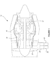
- Fig. 1 illustrates a gas turbine engine 10 of a type preferably provided for use in subsonic flight, generally comprising in serial flow communication a fan 12 through which ambient air is propelled, a compressor section 14 for pressurizing the air, a combustor 16 in which the compressed air is mixed with fuel and ignited for generating an annular stream of hot combustion gases, and a turbine section 18 for extracting energy from the combustion gases.
- Engine 10 is illustrated as a turbofan engine but may be any other type of gas turbine engine, such as turboprop and turboshaft, or any other type of engine or motor, such as a diesel engine.
- the engine 10 may be an aircraft engine, an automobile engine, a power plant engine, and the like. In the case of an aircraft engine, engine 10 may be a main engine or an auxiliary power unit. Other embodiments may also apply.
- a gearbox 20 forms part of the gas turbine engine 10 and is used to drive accessories such as fuel pumps, oil pumps, engine starters, and generators.
- Two generators 22, 24 are fitted into the gearbox 20 for converting mechanical energy from the engine 10 into electrical energy.
- the engine 10 drives the gearbox 20 which in turn drives the generators 22, 24.
- the two generators 22, 24 may feed separate power grids of an aircraft electrical power system, or they may be used on a same power grid.
- the gearbox 20 mechanically links together the generators 22, 24, causing them to rotate at a same frequency.
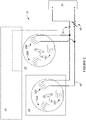
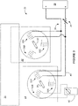
- FIG. 2 illustrates an example system 25 for synchronizing at least two generators, such as generator 22 and generator 24.
- Generator 22 is mechanically coupled to engine 10 via gearbox 20.
- Generator 24 is mechanically uncoupled from gearbox 20 and engine 10.
- gearbox 20 is one embodiment by which the generators 22, 24 may be mechanically coupled to the engine 10.
- Generators 22, 24 are illustrated as polyphase generators, and more specifically 3-phase generators, but may also be single-phase or contain any other number of phases suitable for the application for which they are intended. In some embodiments, generators 22 and 24 are identical.
- the stator of generator 22 has three electromagnets 28a, 28b, 28c, each one composed of a solenoid wrapped around a conductive core.
- the rotor of generator 22 is composed of a magnet 30, having a north pole (N) and a south pole (S).
- the stator of generator 24 has three electromagnets 32a, 32b, 32c, each one composed of a solenoid wrapped around a conductive core.
- the rotor of generator 24 is composed of a magnet 34, having a north pole (N) and a south pole (S).
- Each electromagnet represents a respective phase of a corresponding generator.
- Electromagnets 28a, 32a correspond to a first phase
- electromagnets 28b, 32b correspond to a second phase
- electromagnets 28c, 32c correspond to a third phase.
- the windings on each pair of electromagnets 28a, 32a, 28b, 32b, and 28c, 32c have a same indexing.
- a power source 26 is connected in parallel to generator 22 and generator 24 while generator 22 is mechanically coupled to the gearbox 20 and generator 24 is mechanically uncoupled from the gearbox 20. Note that generator 22 may also be mechanically uncoupled from the gearbox 20 at this stage, but only the embodiment with generator 22 mechanically coupled to the gearbox 20 is illustrated for simplicity.
- the power source 26 may be any type of device capable of supplying electric energy to a load, including stand-alone devices and devices built into larger devices.
- the power source 26 may be a battery, a fuel cell, a generator, an alternator, a solar power converter, and the like.
- the power source 26 may be independent from the engine 10 and/or from an aircraft in which the engine 10 is installed.
- the power source 26 is connected across a same phase in both generators 22 and 24, namely electromagnets 28a and 32a.
- power source 26 may be connected across electromagnets 28b and 32b, or across electromagnets 28c and 32c.
- Cables 40 are used to connect the positive terminal of power source 26 to a first end of the solenoid forming electromagnet 28a and a first end of the solenoid forming electromagnet 32a, and to connect the negative terminal of power source 26 to a second end of the solenoid forming electromagnet 28a and a second end of the solenoid forming electromagnet 32a.
- the same respective ends of electromagnets 28a, 32a are connected to the positive and negative terminals of the power source 26, respectively. Any type of suitable wiring may be used for cables 40.
- a switching device 36 is provided in the path between the power source 26 and the generators 22, 24, to selectively open and close the circuit.
- the act of connecting cables 40 to either end of the circuit i.e. the battery terminals at one end and the electromagnets 28a, 32a at the other end, serves the same function as switching device 36.
- one or both ends of the circuit may be left unconnected until power is to be applied from the power source 26 to the generators 22, 24.
- a variable resistor 38 is provided in the path between the power source 26 and the generators 22, 24 to modulate the power applied from the power source 26 to the generators 22, 24.
- power modulation may be performed manually, for example by limiting the amount of time during which the cables are connected to the power source 26 and/or the generators 22, 24 or by connecting the cables 40 intermittently.
- the power source 26 may have a power modulating function integrated therein.
- one or more impedance meter 42 is used to confirm that the rotors 30, 34 have stopped rotating and are fixed.
- the impedance meter 42 may also be used to confirm that the same impedance can be read across electromagnet 28a and electromagnet 32a.
- a single impedance meter 42 may be alternately connected to an electromagnet of generator 22 and an electromagnet of generator 24.
- two impedance meters 42 may be used, one connected to each generator 22, 24. Impedance may be measured across the same electromagnet to which power is applied, namely electromagnets 28a, 32a, or to one of the other electromagnets in the generator (as illustrated). Any type of impedance measuring instrument may be used, such as a multimeter or an LCR meter.
- generator 24 is then mechanically coupled to engine 10 via gearbox 20.
- the mechanical coupling will allow the generators 22, 24 to be aligned in frequency when the engine is started, as both generators 22, 24 will be rotated together via gearbox 20. Cables 40 may be removed from generators 22, 24 before or after generator 24 is mechanically coupled to the engine 10.
- Figures 5A and 5B are flowcharts of example methods 50 1 , 50 2 for synchronizing at least two generators for an engine, such as generators 22, 24 for engine 10.
- the first generator is mechanically coupled to the engine.
- mechanically coupling the first generator may comprise fitting the first generator to a gearbox of the engine.
- another structural device may be used to couple the engine and generator so as to have the shaft of the engine and the rotor of the generator rotate together.
- a power source such as power source 26, is connected in parallel to the first generator and the second generator, across a same respective phase of a stator in both generators.
- the power source is a battery external to the engine.
- power from the power source is applied to the first generator and the second generator to align the rotor of each generator with its own stator. In some embodiments, this comprises closing a switch connected between the power source and the first generator and second generator. In some embodiments, a variable resistor may also be adjusted until the rotors of each generator rotates to a fixed position.
- impedance is measured across the phase of the stator in each generator in order to confirm phase alignment between the two generators. This may be done using one or two impedance measuring devices. Also optionally at 60, the power source is disconnected from the first generator and the second generator once the two generators are aligned in phase.
- the second generator is mechanically coupled to the engine, for example via the same gearbox as the first generator.
- the two generators are then synchronized as they are aligned in both frequency and in phase.
- the power source is connected in parallel to the first and second generators while both the first generator and the second generator are mechanically uncoupled from the engine.
- Mechanically coupling the first generator to the engine, as per 52, may thus be performed later in the method 50 2 , such as before mechanically coupling the second generator to the engine at 62 as illustrated.
- mechanically coupling the first generator to the engine may be performed after mechanically coupling the second generator to the engine at 62, or after connecting the power source in parallel to the first and second generators at 54, or after applying power from the power source to the first and second generators at 56.
- the generators are aligned to a non-zero phase. This may be done, for example, by connecting a second power source to a second phase of at least one of the two generators.
- a second power source may be connected across electromagnet 32b in generator 24.
- magnet 34 will rotate to a position located between the two electromagnets 32a, 32b. Having magnet 30 and magnet 34 set to different positions causes the desired non-zero phase alignment. This may be done, for example, in an effort to create a different loading between generators 22, 24.
- the second power source may be connected across electromagnet 32b in generator 24 and across electromagnet 28b in generator 22. Power may then be applied so as to cause magnets 30, 34 to rotate to a same position located substantially centrally between electromagnets 28b, 28a and 32b, 32a, respectively.
- a shift left to either of the two magnets 30, 34 can set the phase difference between the two generators to a negative non-zero value.
- a shift right to either of the two magnets 30, 34 can set the phase difference to a positive non-zero value.
- the method and system may be performed as the time of installation of an engine and/or at engine maintenance.
- the single gearbox 20 may be two separate gearboxes that are mechanically coupled together. Still other modifications which fall within the scope of the present invention will be apparent to those skilled in the art, in light of a review of this disclosure, and such modifications are intended to fall within the appended claims.
Landscapes
- Engineering & Computer Science (AREA)
- Chemical & Material Sciences (AREA)
- Combustion & Propulsion (AREA)
- Power Engineering (AREA)
- Mechanical Engineering (AREA)
- General Engineering & Computer Science (AREA)
- Connection Of Motors, Electrical Generators, Mechanical Devices, And The Like (AREA)
- Supply And Distribution Of Alternating Current (AREA)
Applications Claiming Priority (1)
| Application Number | Priority Date | Filing Date | Title |
|---|---|---|---|
| US15/418,856 US10224848B2 (en) | 2017-01-30 | 2017-01-30 | Method and system for synchronizing generators |
Publications (2)
| Publication Number | Publication Date |
|---|---|
| EP3355434A1 true EP3355434A1 (de) | 2018-08-01 |
| EP3355434B1 EP3355434B1 (de) | 2019-12-18 |
Family
ID=61094322
Family Applications (1)
| Application Number | Title | Priority Date | Filing Date |
|---|---|---|---|
| EP18154153.3A Active EP3355434B1 (de) | 2017-01-30 | 2018-01-30 | Verfahren und system zum synchronisieren von generatoren |
Country Status (3)
| Country | Link |
|---|---|
| US (1) | US10224848B2 (de) |
| EP (1) | EP3355434B1 (de) |
| CA (1) | CA2991837C (de) |
Families Citing this family (1)
| Publication number | Priority date | Publication date | Assignee | Title |
|---|---|---|---|---|
| US10868483B1 (en) * | 2019-06-03 | 2020-12-15 | Hamilton Sundstrand Corporation | DC generator system |
Citations (3)
| Publication number | Priority date | Publication date | Assignee | Title |
|---|---|---|---|---|
| JPS5763435U (de) * | 1980-10-02 | 1982-04-15 | ||
| US20060061336A1 (en) * | 2004-09-21 | 2006-03-23 | Honeywell International | Method and apparatus for controlling an engine start system |
| US20070040383A1 (en) * | 2005-08-17 | 2007-02-22 | Hamilton Sundstrand Corporation | Electric engine start with two motors and single motor drive |
Family Cites Families (15)
| Publication number | Priority date | Publication date | Assignee | Title |
|---|---|---|---|---|
| US3611080A (en) * | 1969-09-19 | 1971-10-05 | Gen Electric Canada | Common load sharing by two or more synchronous motors |
| US4208620A (en) * | 1975-11-20 | 1980-06-17 | Siemens-Allis, Inc. | Plural electric motors driving common load and having interconnections for load control |
| JPS5763435A (en) | 1980-10-02 | 1982-04-16 | Yokohama Rubber Co Ltd:The | Tackiness measuring device |
| CA2283943C (en) * | 1997-02-07 | 2009-02-03 | Marks, Hildegard K. (Executrix For The Deceased Inventor) | Method and apparatus for compensating a line synchronous generator |
| WO1999019962A1 (en) * | 1997-10-16 | 1999-04-22 | Omnidyne Inc. | Generators and transformers with toroidally wound stator winding |
| IL124923A (en) * | 1998-06-15 | 2003-02-12 | Mekler Dan | Rotary machine |
| US7692335B2 (en) * | 2004-11-22 | 2010-04-06 | Honeywell International Inc. | Method and apparatus for mechanical phase synchronization of multiple AC generators |
| US7971499B2 (en) | 2004-11-22 | 2011-07-05 | Honeywell International Inc. | Adjustable gear position arrangement for synchronization of multiple generators |
| US7319307B2 (en) * | 2005-12-16 | 2008-01-15 | General Electric Company | Power balancing of multiple synchronized generators |
| US7723931B2 (en) * | 2006-05-31 | 2010-05-25 | Pratt & Whitney Canada Corp. | Starting a gas turbine engine using a sensorless, brushless motor |
| US7405542B1 (en) * | 2006-12-20 | 2008-07-29 | The Boeing Company | Generator synchronization method on a common drive source and apparatus therefor |
| GB0715472D0 (en) * | 2007-08-09 | 2007-09-19 | Rolls Royce Plc | An electrical machine |
| US20130168960A1 (en) * | 2012-01-03 | 2013-07-04 | ComAp a.s. | Method and apparatus for pole-slip detection in synchronous generators |
| KR101500355B1 (ko) * | 2013-07-01 | 2015-03-09 | 현대자동차 주식회사 | 하이브리드 자동차의 동력전달장치 |
| US9762160B2 (en) * | 2013-12-23 | 2017-09-12 | Generac Power Systems, Inc. | Method of controlling multiple parallel-connected generators |
-
2017
- 2017-01-30 US US15/418,856 patent/US10224848B2/en active Active
-
2018
- 2018-01-12 CA CA2991837A patent/CA2991837C/en active Active
- 2018-01-30 EP EP18154153.3A patent/EP3355434B1/de active Active
Patent Citations (3)
| Publication number | Priority date | Publication date | Assignee | Title |
|---|---|---|---|---|
| JPS5763435U (de) * | 1980-10-02 | 1982-04-15 | ||
| US20060061336A1 (en) * | 2004-09-21 | 2006-03-23 | Honeywell International | Method and apparatus for controlling an engine start system |
| US20070040383A1 (en) * | 2005-08-17 | 2007-02-22 | Hamilton Sundstrand Corporation | Electric engine start with two motors and single motor drive |
Also Published As
| Publication number | Publication date |
|---|---|
| CA2991837A1 (en) | 2018-07-30 |
| EP3355434B1 (de) | 2019-12-18 |
| CA2991837C (en) | 2025-09-02 |
| US20180219502A1 (en) | 2018-08-02 |
| US10224848B2 (en) | 2019-03-05 |
Similar Documents
| Publication | Publication Date | Title |
|---|---|---|
| EP1018211B1 (de) | Verfahren und vorrichtung zur kompensation eines synchrongenerators mit sektoren | |
| JP5656404B2 (ja) | 電動装置の起動及び運転方法およびそのシステム | |
| EP2767705B1 (de) | System zum Neustarten während des Fluges eines mehrwelligen Turbomotors | |
| US8823334B2 (en) | Method for starting an electric motor | |
| US12278494B2 (en) | Method for black-starting an electrical grid | |
| GB1580155A (en) | Quadrature axis field brushless exciter | |
| JP2010503791A5 (de) | ||
| US20140145536A1 (en) | Method and apparatus for compensating a line synchronous generator | |
| CN104426444A (zh) | 一种用于涡轮发动机的恒频起动器/发电机 | |
| US7692335B2 (en) | Method and apparatus for mechanical phase synchronization of multiple AC generators | |
| US7227338B2 (en) | Fixed frequency electrical generation system with induction coupler and use thereof in an aircraft | |
| US10312781B2 (en) | Multiple coil electric generator in turbine engine | |
| EP3355434B1 (de) | Verfahren und system zum synchronisieren von generatoren | |
| US5886505A (en) | Apparatus and method for bringing on line a large synchronous condenser that cannot be started by an across the line start | |
| CN113228450A (zh) | 混合同步调相机和发电单元 | |
| RU2645866C2 (ru) | Электромеханическая система приведения в действие и/или генерирования, содержащая электрическую изоляцию между источником электрического напряжения и нагрузкой | |
| US20030052565A1 (en) | Method and apparatus for compensating a line synchronous generator | |
| Ismagilov et al. | Experimental Studies of the High-Temperature Starter-Generator for Aircraft Engine. | |
| KR100980063B1 (ko) | 3상 라인 동기 발전기의 위상 정렬을 결정하는 방법 | |
| Racewicz et al. | Feasibility study of the electric power generation unit start-up using the three-phase synchronous generator with the ac exciter | |
| Ranayhossaini et al. | Laboratory Experiments on a Doubly Fed Induction Generator (DFIG) for Wind Turbine Application | |
| Gerling | Synchronous Machines |
Legal Events
| Date | Code | Title | Description |
|---|---|---|---|
| PUAI | Public reference made under article 153(3) epc to a published international application that has entered the european phase |
Free format text: ORIGINAL CODE: 0009012 |
|
| STAA | Information on the status of an ep patent application or granted ep patent |
Free format text: STATUS: THE APPLICATION HAS BEEN PUBLISHED |
|
| AK | Designated contracting states |
Kind code of ref document: A1 Designated state(s): AL AT BE BG CH CY CZ DE DK EE ES FI FR GB GR HR HU IE IS IT LI LT LU LV MC MK MT NL NO PL PT RO RS SE SI SK SM TR |
|
| AX | Request for extension of the european patent |
Extension state: BA ME |
|
| STAA | Information on the status of an ep patent application or granted ep patent |
Free format text: STATUS: REQUEST FOR EXAMINATION WAS MADE |
|
| 17P | Request for examination filed |
Effective date: 20190121 |
|
| RBV | Designated contracting states (corrected) |
Designated state(s): AL AT BE BG CH CY CZ DE DK EE ES FI FR GB GR HR HU IE IS IT LI LT LU LV MC MK MT NL NO PL PT RO RS SE SI SK SM TR |
|
| GRAP | Despatch of communication of intention to grant a patent |
Free format text: ORIGINAL CODE: EPIDOSNIGR1 |
|
| STAA | Information on the status of an ep patent application or granted ep patent |
Free format text: STATUS: GRANT OF PATENT IS INTENDED |
|
| RIC1 | Information provided on ipc code assigned before grant |
Ipc: F02C 7/268 20060101ALI20190605BHEP Ipc: H02K 7/18 20060101ALI20190605BHEP Ipc: H02J 3/40 20060101ALI20190605BHEP Ipc: H02P 9/02 20060101ALI20190605BHEP Ipc: F02N 11/00 20060101ALI20190605BHEP Ipc: F02B 63/04 20060101ALI20190605BHEP Ipc: F01D 15/12 20060101ALI20190605BHEP Ipc: H02J 1/06 20060101AFI20190605BHEP Ipc: F01D 15/10 20060101ALI20190605BHEP Ipc: H02K 7/116 20060101ALI20190605BHEP Ipc: F02N 11/04 20060101ALI20190605BHEP Ipc: H02P 9/06 20060101ALI20190605BHEP Ipc: F02C 7/32 20060101ALI20190605BHEP |
|
| INTG | Intention to grant announced |
Effective date: 20190628 |
|
| GRAS | Grant fee paid |
Free format text: ORIGINAL CODE: EPIDOSNIGR3 |
|
| GRAA | (expected) grant |
Free format text: ORIGINAL CODE: 0009210 |
|
| STAA | Information on the status of an ep patent application or granted ep patent |
Free format text: STATUS: THE PATENT HAS BEEN GRANTED |
|
| AK | Designated contracting states |
Kind code of ref document: B1 Designated state(s): AL AT BE BG CH CY CZ DE DK EE ES FI FR GB GR HR HU IE IS IT LI LT LU LV MC MK MT NL NO PL PT RO RS SE SI SK SM TR |
|
| REG | Reference to a national code |
Ref country code: CH Ref legal event code: EP |
|
| REG | Reference to a national code |
Ref country code: IE Ref legal event code: FG4D |
|
| REG | Reference to a national code |
Ref country code: DE Ref legal event code: R096 Ref document number: 602018001605 Country of ref document: DE |
|
| REG | Reference to a national code |
Ref country code: AT Ref legal event code: REF Ref document number: 1215624 Country of ref document: AT Kind code of ref document: T Effective date: 20200115 |
|
| REG | Reference to a national code |
Ref country code: NL Ref legal event code: MP Effective date: 20191218 |
|
| PG25 | Lapsed in a contracting state [announced via postgrant information from national office to epo] |
Ref country code: FI Free format text: LAPSE BECAUSE OF FAILURE TO SUBMIT A TRANSLATION OF THE DESCRIPTION OR TO PAY THE FEE WITHIN THE PRESCRIBED TIME-LIMIT Effective date: 20191218 Ref country code: BG Free format text: LAPSE BECAUSE OF FAILURE TO SUBMIT A TRANSLATION OF THE DESCRIPTION OR TO PAY THE FEE WITHIN THE PRESCRIBED TIME-LIMIT Effective date: 20200318 Ref country code: GR Free format text: LAPSE BECAUSE OF FAILURE TO SUBMIT A TRANSLATION OF THE DESCRIPTION OR TO PAY THE FEE WITHIN THE PRESCRIBED TIME-LIMIT Effective date: 20200319 Ref country code: LT Free format text: LAPSE BECAUSE OF FAILURE TO SUBMIT A TRANSLATION OF THE DESCRIPTION OR TO PAY THE FEE WITHIN THE PRESCRIBED TIME-LIMIT Effective date: 20191218 Ref country code: SE Free format text: LAPSE BECAUSE OF FAILURE TO SUBMIT A TRANSLATION OF THE DESCRIPTION OR TO PAY THE FEE WITHIN THE PRESCRIBED TIME-LIMIT Effective date: 20191218 Ref country code: LV Free format text: LAPSE BECAUSE OF FAILURE TO SUBMIT A TRANSLATION OF THE DESCRIPTION OR TO PAY THE FEE WITHIN THE PRESCRIBED TIME-LIMIT Effective date: 20191218 Ref country code: NO Free format text: LAPSE BECAUSE OF FAILURE TO SUBMIT A TRANSLATION OF THE DESCRIPTION OR TO PAY THE FEE WITHIN THE PRESCRIBED TIME-LIMIT Effective date: 20200318 |
|
| REG | Reference to a national code |
Ref country code: LT Ref legal event code: MG4D |
|
| PG25 | Lapsed in a contracting state [announced via postgrant information from national office to epo] |
Ref country code: HR Free format text: LAPSE BECAUSE OF FAILURE TO SUBMIT A TRANSLATION OF THE DESCRIPTION OR TO PAY THE FEE WITHIN THE PRESCRIBED TIME-LIMIT Effective date: 20191218 Ref country code: RS Free format text: LAPSE BECAUSE OF FAILURE TO SUBMIT A TRANSLATION OF THE DESCRIPTION OR TO PAY THE FEE WITHIN THE PRESCRIBED TIME-LIMIT Effective date: 20191218 |
|
| PG25 | Lapsed in a contracting state [announced via postgrant information from national office to epo] |
Ref country code: AL Free format text: LAPSE BECAUSE OF FAILURE TO SUBMIT A TRANSLATION OF THE DESCRIPTION OR TO PAY THE FEE WITHIN THE PRESCRIBED TIME-LIMIT Effective date: 20191218 |
|
| PG25 | Lapsed in a contracting state [announced via postgrant information from national office to epo] |
Ref country code: CZ Free format text: LAPSE BECAUSE OF FAILURE TO SUBMIT A TRANSLATION OF THE DESCRIPTION OR TO PAY THE FEE WITHIN THE PRESCRIBED TIME-LIMIT Effective date: 20191218 Ref country code: RO Free format text: LAPSE BECAUSE OF FAILURE TO SUBMIT A TRANSLATION OF THE DESCRIPTION OR TO PAY THE FEE WITHIN THE PRESCRIBED TIME-LIMIT Effective date: 20191218 Ref country code: NL Free format text: LAPSE BECAUSE OF FAILURE TO SUBMIT A TRANSLATION OF THE DESCRIPTION OR TO PAY THE FEE WITHIN THE PRESCRIBED TIME-LIMIT Effective date: 20191218 Ref country code: PT Free format text: LAPSE BECAUSE OF FAILURE TO SUBMIT A TRANSLATION OF THE DESCRIPTION OR TO PAY THE FEE WITHIN THE PRESCRIBED TIME-LIMIT Effective date: 20200513 Ref country code: EE Free format text: LAPSE BECAUSE OF FAILURE TO SUBMIT A TRANSLATION OF THE DESCRIPTION OR TO PAY THE FEE WITHIN THE PRESCRIBED TIME-LIMIT Effective date: 20191218 |
|
| PG25 | Lapsed in a contracting state [announced via postgrant information from national office to epo] |
Ref country code: SK Free format text: LAPSE BECAUSE OF FAILURE TO SUBMIT A TRANSLATION OF THE DESCRIPTION OR TO PAY THE FEE WITHIN THE PRESCRIBED TIME-LIMIT Effective date: 20191218 Ref country code: IS Free format text: LAPSE BECAUSE OF FAILURE TO SUBMIT A TRANSLATION OF THE DESCRIPTION OR TO PAY THE FEE WITHIN THE PRESCRIBED TIME-LIMIT Effective date: 20200418 Ref country code: SM Free format text: LAPSE BECAUSE OF FAILURE TO SUBMIT A TRANSLATION OF THE DESCRIPTION OR TO PAY THE FEE WITHIN THE PRESCRIBED TIME-LIMIT Effective date: 20191218 |
|
| REG | Reference to a national code |
Ref country code: DE Ref legal event code: R097 Ref document number: 602018001605 Country of ref document: DE |
|
| PG25 | Lapsed in a contracting state [announced via postgrant information from national office to epo] |
Ref country code: MC Free format text: LAPSE BECAUSE OF FAILURE TO SUBMIT A TRANSLATION OF THE DESCRIPTION OR TO PAY THE FEE WITHIN THE PRESCRIBED TIME-LIMIT Effective date: 20191218 |
|
| REG | Reference to a national code |
Ref country code: AT Ref legal event code: MK05 Ref document number: 1215624 Country of ref document: AT Kind code of ref document: T Effective date: 20191218 Ref country code: BE Ref legal event code: MM Effective date: 20200131 |
|
| PLBE | No opposition filed within time limit |
Free format text: ORIGINAL CODE: 0009261 |
|
| STAA | Information on the status of an ep patent application or granted ep patent |
Free format text: STATUS: NO OPPOSITION FILED WITHIN TIME LIMIT |
|
| PG25 | Lapsed in a contracting state [announced via postgrant information from national office to epo] |
Ref country code: ES Free format text: LAPSE BECAUSE OF FAILURE TO SUBMIT A TRANSLATION OF THE DESCRIPTION OR TO PAY THE FEE WITHIN THE PRESCRIBED TIME-LIMIT Effective date: 20191218 Ref country code: DK Free format text: LAPSE BECAUSE OF FAILURE TO SUBMIT A TRANSLATION OF THE DESCRIPTION OR TO PAY THE FEE WITHIN THE PRESCRIBED TIME-LIMIT Effective date: 20191218 Ref country code: LU Free format text: LAPSE BECAUSE OF NON-PAYMENT OF DUE FEES Effective date: 20200130 |
|
| 26N | No opposition filed |
Effective date: 20200921 |
|
| PG25 | Lapsed in a contracting state [announced via postgrant information from national office to epo] |
Ref country code: SI Free format text: LAPSE BECAUSE OF FAILURE TO SUBMIT A TRANSLATION OF THE DESCRIPTION OR TO PAY THE FEE WITHIN THE PRESCRIBED TIME-LIMIT Effective date: 20191218 Ref country code: AT Free format text: LAPSE BECAUSE OF FAILURE TO SUBMIT A TRANSLATION OF THE DESCRIPTION OR TO PAY THE FEE WITHIN THE PRESCRIBED TIME-LIMIT Effective date: 20191218 Ref country code: BE Free format text: LAPSE BECAUSE OF NON-PAYMENT OF DUE FEES Effective date: 20200131 |
|
| PG25 | Lapsed in a contracting state [announced via postgrant information from national office to epo] |
Ref country code: IE Free format text: LAPSE BECAUSE OF NON-PAYMENT OF DUE FEES Effective date: 20200130 Ref country code: IT Free format text: LAPSE BECAUSE OF FAILURE TO SUBMIT A TRANSLATION OF THE DESCRIPTION OR TO PAY THE FEE WITHIN THE PRESCRIBED TIME-LIMIT Effective date: 20191218 |
|
| PG25 | Lapsed in a contracting state [announced via postgrant information from national office to epo] |
Ref country code: PL Free format text: LAPSE BECAUSE OF FAILURE TO SUBMIT A TRANSLATION OF THE DESCRIPTION OR TO PAY THE FEE WITHIN THE PRESCRIBED TIME-LIMIT Effective date: 20191218 |
|
| REG | Reference to a national code |
Ref country code: CH Ref legal event code: PL |
|
| PG25 | Lapsed in a contracting state [announced via postgrant information from national office to epo] |
Ref country code: LI Free format text: LAPSE BECAUSE OF NON-PAYMENT OF DUE FEES Effective date: 20210131 Ref country code: CH Free format text: LAPSE BECAUSE OF NON-PAYMENT OF DUE FEES Effective date: 20210131 |
|
| PG25 | Lapsed in a contracting state [announced via postgrant information from national office to epo] |
Ref country code: TR Free format text: LAPSE BECAUSE OF FAILURE TO SUBMIT A TRANSLATION OF THE DESCRIPTION OR TO PAY THE FEE WITHIN THE PRESCRIBED TIME-LIMIT Effective date: 20191218 Ref country code: MT Free format text: LAPSE BECAUSE OF FAILURE TO SUBMIT A TRANSLATION OF THE DESCRIPTION OR TO PAY THE FEE WITHIN THE PRESCRIBED TIME-LIMIT Effective date: 20191218 Ref country code: CY Free format text: LAPSE BECAUSE OF FAILURE TO SUBMIT A TRANSLATION OF THE DESCRIPTION OR TO PAY THE FEE WITHIN THE PRESCRIBED TIME-LIMIT Effective date: 20191218 |
|
| PG25 | Lapsed in a contracting state [announced via postgrant information from national office to epo] |
Ref country code: MK Free format text: LAPSE BECAUSE OF FAILURE TO SUBMIT A TRANSLATION OF THE DESCRIPTION OR TO PAY THE FEE WITHIN THE PRESCRIBED TIME-LIMIT Effective date: 20191218 |
|
| P01 | Opt-out of the competence of the unified patent court (upc) registered |
Effective date: 20230530 |
|
| PGFP | Annual fee paid to national office [announced via postgrant information from national office to epo] |
Ref country code: GB Payment date: 20251220 Year of fee payment: 9 |
|
| PGFP | Annual fee paid to national office [announced via postgrant information from national office to epo] |
Ref country code: FR Payment date: 20251217 Year of fee payment: 9 |
|
| PGFP | Annual fee paid to national office [announced via postgrant information from national office to epo] |
Ref country code: DE Payment date: 20251217 Year of fee payment: 9 |