EP3355322B1 - Coil component - Google Patents
Coil component Download PDFInfo
- Publication number
- EP3355322B1 EP3355322B1 EP18152911.6A EP18152911A EP3355322B1 EP 3355322 B1 EP3355322 B1 EP 3355322B1 EP 18152911 A EP18152911 A EP 18152911A EP 3355322 B1 EP3355322 B1 EP 3355322B1
- Authority
- EP
- European Patent Office
- Prior art keywords
- limiting protruding
- portions
- protruding portion
- winding
- coil
- Prior art date
- Legal status (The legal status is an assumption and is not a legal conclusion. Google has not performed a legal analysis and makes no representation as to the accuracy of the status listed.)
- Active
Links
- 238000004804 winding Methods 0.000 claims description 174
- 230000002093 peripheral effect Effects 0.000 claims description 10
- 230000000149 penetrating effect Effects 0.000 claims description 2
- 125000006850 spacer group Chemical group 0.000 description 18
- 238000000034 method Methods 0.000 description 8
- 238000000638 solvent extraction Methods 0.000 description 7
- 238000004519 manufacturing process Methods 0.000 description 5
- 238000003780 insertion Methods 0.000 description 4
- 230000037431 insertion Effects 0.000 description 4
- 230000000694 effects Effects 0.000 description 3
- RYGMFSIKBFXOCR-UHFFFAOYSA-N Copper Chemical compound [Cu] RYGMFSIKBFXOCR-UHFFFAOYSA-N 0.000 description 2
- 230000002500 effect on skin Effects 0.000 description 2
- 230000002349 favourable effect Effects 0.000 description 2
- 230000017525 heat dissipation Effects 0.000 description 2
- 239000000470 constituent Substances 0.000 description 1
- 238000001816 cooling Methods 0.000 description 1
- 230000008878 coupling Effects 0.000 description 1
- 238000010168 coupling process Methods 0.000 description 1
- 238000005859 coupling reaction Methods 0.000 description 1
- 238000010586 diagram Methods 0.000 description 1
- 238000006073 displacement reaction Methods 0.000 description 1
- 239000000696 magnetic material Substances 0.000 description 1
- 239000002184 metal Substances 0.000 description 1
- 229910052751 metal Inorganic materials 0.000 description 1
- 230000004048 modification Effects 0.000 description 1
- 238000012986 modification Methods 0.000 description 1
- 239000011347 resin Substances 0.000 description 1
- 229920005989 resin Polymers 0.000 description 1
Images


Classifications
-
- H—ELECTRICITY
- H01—ELECTRIC ELEMENTS
- H01F—MAGNETS; INDUCTANCES; TRANSFORMERS; SELECTION OF MATERIALS FOR THEIR MAGNETIC PROPERTIES
- H01F27/00—Details of transformers or inductances, in general
- H01F27/28—Coils; Windings; Conductive connections
- H01F27/30—Fastening or clamping coils, windings, or parts thereof together; Fastening or mounting coils or windings on core, casing, or other support
- H01F27/306—Fastening or mounting coils or windings on core, casing or other support
-
- H—ELECTRICITY
- H01—ELECTRIC ELEMENTS
- H01F—MAGNETS; INDUCTANCES; TRANSFORMERS; SELECTION OF MATERIALS FOR THEIR MAGNETIC PROPERTIES
- H01F27/00—Details of transformers or inductances, in general
- H01F27/28—Coils; Windings; Conductive connections
- H01F27/32—Insulating of coils, windings, or parts thereof
- H01F27/324—Insulation between coil and core, between different winding sections, around the coil; Other insulation structures
- H01F27/325—Coil bobbins
-
- H—ELECTRICITY
- H01—ELECTRIC ELEMENTS
- H01F—MAGNETS; INDUCTANCES; TRANSFORMERS; SELECTION OF MATERIALS FOR THEIR MAGNETIC PROPERTIES
- H01F27/00—Details of transformers or inductances, in general
- H01F27/28—Coils; Windings; Conductive connections
- H01F27/2823—Wires
-
- H—ELECTRICITY
- H01—ELECTRIC ELEMENTS
- H01F—MAGNETS; INDUCTANCES; TRANSFORMERS; SELECTION OF MATERIALS FOR THEIR MAGNETIC PROPERTIES
- H01F27/00—Details of transformers or inductances, in general
- H01F27/28—Coils; Windings; Conductive connections
- H01F27/32—Insulating of coils, windings, or parts thereof
- H01F27/323—Insulation between winding turns, between winding layers
-
- H—ELECTRICITY
- H01—ELECTRIC ELEMENTS
- H01F—MAGNETS; INDUCTANCES; TRANSFORMERS; SELECTION OF MATERIALS FOR THEIR MAGNETIC PROPERTIES
- H01F37/00—Fixed inductances not covered by group H01F17/00
-
- H—ELECTRICITY
- H01—ELECTRIC ELEMENTS
- H01F—MAGNETS; INDUCTANCES; TRANSFORMERS; SELECTION OF MATERIALS FOR THEIR MAGNETIC PROPERTIES
- H01F41/00—Apparatus or processes specially adapted for manufacturing or assembling magnets, inductances or transformers; Apparatus or processes specially adapted for manufacturing materials characterised by their magnetic properties
- H01F41/02—Apparatus or processes specially adapted for manufacturing or assembling magnets, inductances or transformers; Apparatus or processes specially adapted for manufacturing materials characterised by their magnetic properties for manufacturing cores, coils, or magnets
- H01F41/04—Apparatus or processes specially adapted for manufacturing or assembling magnets, inductances or transformers; Apparatus or processes specially adapted for manufacturing materials characterised by their magnetic properties for manufacturing cores, coils, or magnets for manufacturing coils
- H01F41/06—Coil winding
- H01F41/061—Winding flat conductive wires or sheets
-
- H—ELECTRICITY
- H01—ELECTRIC ELEMENTS
- H01F—MAGNETS; INDUCTANCES; TRANSFORMERS; SELECTION OF MATERIALS FOR THEIR MAGNETIC PROPERTIES
- H01F41/00—Apparatus or processes specially adapted for manufacturing or assembling magnets, inductances or transformers; Apparatus or processes specially adapted for manufacturing materials characterised by their magnetic properties
- H01F41/02—Apparatus or processes specially adapted for manufacturing or assembling magnets, inductances or transformers; Apparatus or processes specially adapted for manufacturing materials characterised by their magnetic properties for manufacturing cores, coils, or magnets
- H01F41/04—Apparatus or processes specially adapted for manufacturing or assembling magnets, inductances or transformers; Apparatus or processes specially adapted for manufacturing materials characterised by their magnetic properties for manufacturing cores, coils, or magnets for manufacturing coils
- H01F41/06—Coil winding
- H01F41/098—Mandrels; Formers
-
- H—ELECTRICITY
- H01—ELECTRIC ELEMENTS
- H01F—MAGNETS; INDUCTANCES; TRANSFORMERS; SELECTION OF MATERIALS FOR THEIR MAGNETIC PROPERTIES
- H01F5/00—Coils
- H01F5/02—Coils wound on non-magnetic supports, e.g. formers
-
- H—ELECTRICITY
- H01—ELECTRIC ELEMENTS
- H01F—MAGNETS; INDUCTANCES; TRANSFORMERS; SELECTION OF MATERIALS FOR THEIR MAGNETIC PROPERTIES
- H01F27/00—Details of transformers or inductances, in general
- H01F27/006—Details of transformers or inductances, in general with special arrangement or spacing of turns of the winding(s), e.g. to produce desired self-resonance
Definitions
- the present invention relates to coil components.
- Document JP 2006-120767 describes a coil component including a core and a coil wound around the outer periphery of the core, in which plural protruding portions, each of which is arranged between winding portions of the coil to determine the position of each winding portion, are formed integrally with the outer peripheral surface of the core.
- This coil component is manufactured in the following manner.
- the core is inserted into the coil in a state where the diameter of the coil is increased by twisting it in a radially expanding direction.
- each protruding portion of the core is arranged between individual winding portions of the coil. In this manner, the coil is wound around the outer periphery of the core.
- a coil is formed by concentrically winding a flat type copper wire, wherein both ends of the flat type copper wire are led out to serve as coil terminals. Furthermore, insulating terminal boards are fixed to a partitioning plate of a coil bobbin nearly in parallel with each other along the axial direction of a main body confronting each other so as to sandwich the main body between them. Pairs of terminal pins are made to penetrate through the terminal boards and in a crosswise direction on each side of the partitioning plate. The terminal pin is formed like a pointed flat type conductive bar.
- Document JP 2006-147927 describes a transformer which is formed by mounting a spacer having a notch provided to coincide with the corner of a core on the side in contact with the core at four corners of the core, and pinching a straight angle winding wound like a coil comprising a primary winding and a secondary winding so that one of cross-sectional longitudinal ends is inserted into a comb-like recess provided on a side face of the spacer for holding the winding.
- the primary winding and the secondary winding are held at a predetermined interval by the protrusion of the spacer.
- the windings are insulated from the core by the body of the spacer to be kept at the interval. A rise in temperature of the transformer is reduced by making cooling air flow between the windings and between the windings and the core.
- the reactor is formed from a combination of a magnetic T-core and a pair of magnetic L-cores.
- a plurality of comb-like separators is placed over a vertical portion of the T-core.
- a wire, with a rectangular cross-section, is wound about the vertical portion of the T-core thereby forming a coil.
- the comb-like separators electrically isolate the wire from adjacent windings and the T-core.
- the L-cores are attached to the T-core such that they flank two sides of the coil.
- a plurality of taps is formed on a side of the coil that is not flanked by one of the L-cores. The taps are formed by extending individual windings further from the T-core than other common windings.
- a hole is formed through the rectangular wire at the taps to provide a secure electrical connection to the wire.
- a coil component which includes:
- the edgewise coil includes the first winding portion that is in pressure contact with the first position-limiting protruding portion toward the second position-limiting protruding portion and the second winding portion that is in pressure contact with the second position-limiting protruding portion toward the first position-limiting protruding portion.
- the edgewise coil is in the state of space winding where respective winding portions from the first winding portion to the second winding portion are spaced apart from each other in the axial direction of the bobbin body.
- the present invention has been made in view of the problem described above, and is to provide a coil component having a structure that can more stably maintain the position of each winding portion of the coil, and also provide a method for manufacturing the coil component.
- the coil component 40 includes an edgewise coil 10 and a bobbin 20 around which the edgewise coil 10 is wound.
- the bobbin 20 includes a tubular bobbin body 20a, and a plurality of position-limiting protruding portions (for example, plural position-limiting protruding portions 21, plural position-limiting protruding portions 22, plural position-limiting protruding portions 23, and plural position-limiting protruding portions 24) that are arranged in a plurality of portions on an outer peripheral surface of the bobbin body 20a and limit the position of each winding portion 11 of the edgewise coil 10 in the axial direction of the bobbin body 20a.
- position-limiting protruding portions for example, plural position-limiting protruding portions 21, plural position-limiting protruding portions 22, plural position-limiting protruding portions 23, and plural position-limiting protruding portions 24
- the plurality of position-limiting protruding portions include a first position-limiting protruding portion (for example, a position-limiting protruding portion 22b illustrated in Fig. 9 and so on) and a second position-limiting protruding portion (for example, a position-limiting protruding portion 22z illustrated in Fig. 9 and so on) that are disposed at positions different from each other in the axial direction of the bobbin body 20a.
- the edgewise coil 10 includes a first winding portion (for example, a winding portion 11a illustrated in Fig.
- the edgewise coil 10 is in a state of space winding in which respective winding portions 11 from the first winding portion to the second winding portion are spaced apart from each other in the axial direction of the bobbin body 20a.
- the space winding represents a way of winding which is also called pitch winding.
- each of the winding portions 11 is a portion of the edgewise coil 10 that makes one round around the bobbin 20, and the edgewise coil 10 is an assembly of plural winding portions 11 arranged seamlessly in a spiral shape.
- first position-limiting protruding portion and the second position-limiting protruding portion may be arranged alongside each other in the axial direction of the bobbin body 20a, or may be arranged alongside each other in a direction intersecting the axial direction.
- the direction of the second position-limiting protruding portion with respect to the first position-limiting protruding portion (the direction in which the first winding portion is in pressure contact with the first position-limiting protruding portion) and the direction of the first position-limiting protruding portion with respect to the second position-limiting protruding portion (the direction in which the second winding portion is in pressure contact with the second position-limiting protruding portion) may be the axial direction of the bobbin body 20a, or may be the direction intersecting this axial direction.
- the edgewise coil 10 is in a state of space winding in which respective winding portions 11 from the first winding portion to the second winding portion are spaced apart from each other in the axial direction of the bobbin body 20a.
- This configuration enables a stray capacity and a proximity effect between winding portions 11 to be reduced, and hence, it is possible to obtain the coil component 40 with high quality factor, and also possible to reduce the size of the coil component 40.
- the coil component 40 is configured so as to include the edgewise coil 10 using a rectangular wire, and hence, it is possible to reduce the skin effect.
- individual winding portions 11 are space apart from each other, it is possible to achieve a favorable heat dissipation property.
- the first winding portion of the edgewise coil 10 is in pressure contact with the first position-limiting protruding portion toward the second position-limiting protruding portion, and at the same time, the second winding portion of the edgewise coil 10 is in pressure contact with the second position-limiting protruding portion toward the first position-limiting protruding portion.
- the coil component 40 according to this exemplary embodiment can be favorably used as a resonance coil for a field coupling non-contact power supply system, can be used at high frequencies (for example, a band of MHz) and with large electric power (the order of kw or higher), and has a structure that has reduced loss.
- the alternating-current resistance due to stray capacity, proximity effect and core loss causes a large loss.
- the edgewise coil 10 configured with a rectangular wire is used to increase the surface area of the edgewise coil 10, so that the skin effect can be reduced.
- the edgewise coil 10 having a favorable heat dissipation property can be obtained.
- the edgewise coil 10 is formed by spirally winding a metal wire 10a, which is a rectangular wire, and has plural winding portions 11.
- the winding portions 11 each have a winding diameter equivalent to each other.
- the edgewise coil 10 has an outwardly extending piece 13 at both ends thereof.
- the edgewise coil 10 may be configured such that, before wound around the bobbin 20, adjacent winding portions 11 may be in contact with each other (for example, the edgewise coil 10 may be tightly wound in a manner such that no space 12 exists between adjacent winding portions 11).
- the bobbin 20 includes a tubular bobbin body 20a, and plural position-limiting protruding portions arranged in plural portions on the outer peripheral surface of the bobbin body 20a.
- the position-limiting protruding portions are arranged in a plurality of portions in the circumferential direction of the bobbin body 20a (in a direction around the axial center of the bobbin body 20a).
- a plurality of the position-limiting protruding portions are arranged alongside each other along the axial direction of the bobbin body 20a at each of the plurality of portions in the circumferential direction of the bobbin body 20a.
- plural position-limiting protruding portions 21, plural position-limiting protruding portions 22, plural position-limiting protruding portions 23 (see Fig. 3 ), and plural position-limiting protruding portions 24 are arranged on the outer peripheral surface of the bobbin body 20a.
- the plural position-limiting protruding portions 21 are arranged alongside each other along the axial direction of the bobbin body 20a at one position in the circumferential direction of the bobbin body 20 a.
- the plural position-limiting protruding portions 22 are arranged alongside each other along the axial direction of the bobbin body 20a.
- the plural position-limiting protruding portions 23 are arranged alongside each other along the axial direction of the bobbin body 20a.
- the plural position-limiting protruding portions 24 are arranged alongside each other along the axial direction of the bobbin body 20a.
- plural position-limiting protruding portions are arranged respectively at positions equiangularly spaced apart in the circumferential direction of the bobbin body 20a.
- the number of the position-limiting protruding portions 21, the number of the position-limiting protruding portions 22, the number of the position-limiting protruding portions 23, and the number of the position-limiting protruding portions 24 are equal to each other.
- the bobbin 20 includes a position-limiting protruding portion 21a, a position-limiting protruding portion 21b, a position-limiting protruding portion 21c, and a position-limiting protruding portion 21d in the order they appear from the bottom in Fig. 4 , each of which serves as the position-limiting protruding portion 21.
- the bobbin 20 includes a position-limiting protruding portion 22a, a position-limiting protruding portion 22b, a position-limiting protruding portion 22c, and a position-limiting protruding portion 22d in the order they appear from the bottom in Fig. 8 , each of which serves as the position-limiting protruding portion 22.
- the bobbin 20 includes a position-limiting protruding portion 23a (not illustrated), a position-limiting protruding portion 23b (not illustrated), a position-limiting protruding portion 23c (not illustrated), and a position-limiting protruding portion 23d (not illustrated) in the order from bottom to top in Fig. 8 , each of which serves as the position-limiting protruding portion 23.
- the reference characters 23a, 23b, 23c, and 23d are reference characters used for convenience sake and not illustrated in the drawings.
- the bobbin 20 includes a position-limiting protruding portion 24a, a position-limiting protruding portion 24b, a position-limiting protruding portion 24c, and a position-limiting protruding portion 24d in the order they appear from the bottom in Fig. 8 , each of which serves as the position-limiting protruding portion 24.
- the bobbin 20 includes a position-limiting protruding portion 22z, a position-limiting protruding portion 22y, and a position-limiting protruding portion 22x in the order they appear from the top in Fig. 8 , each of which serves as the position-limiting protruding portion 22.
- the bobbin 20 includes a position-limiting protruding portion 21z serving as the position-limiting protruding portion 21 and located at the uppermost position in Fig. 8 .
- the bobbin 20 includes a position-limiting protruding portion 23z (not illustrated) serving as the position-limiting protruding portion 23 and located at the uppermost position in Fig. 8 .
- the reference character 23z is a reference character used for convenience sake and not illustrated in the drawings.
- the bobbin 20 includes a position-limiting protruding portion 24z serving as the position-limiting protruding portion 24 and located at the uppermost position in Fig. 8 .
- the position-limiting protruding portion 22a is disposed at a position higher than the position-limiting protruding portion 21a; the position-limiting protruding portion 23a (not illustrated) is disposed at a position higher than the position-limiting protruding portion 22a; the position-limiting protruding portion 24a is disposed at a position higher than the position-limiting protruding portion 23a; and the position-limiting protruding portion 21b is disposed at a position higher than the position-limiting protruding portion 24a.
- the distance between the position-limiting protruding portion 21a and the position-limiting protruding portion 22a, the distance between the position-limiting protruding portion 22a and the position-limiting protruding portion 23a, the distance between the position-limiting protruding portion 23a and the position-limiting protruding portion 24a, and the distance between the position-limiting protruding portion 24a and the position-limiting protruding portion 21b are, for example, one quarter of the distance between the position-limiting protruding portion 21a and the position-limiting protruding portion 21b.
- position-limiting protruding portions 21 are each arranged at equal intervals in the axial direction of the bobbin body 20a.
- the position-limiting protruding portions 22 are each arranged at equal intervals in the axial direction of the bobbin body 20a.
- the position-limiting protruding portions 23 are each arranged at equal intervals in the axial direction of the bobbin body 20a.
- the position-limiting protruding portions 24 are each arranged at equal intervals in the axial direction of the bobbin body 20a.
- the distance between adjacent position-limiting protruding portions 21, the distance between adjacent position-limiting protruding portions 22, the distance between adjacent position-limiting protruding portions 23, and the distance between adjacent position-limiting protruding portions 24 are equal to each other.
- the position-limiting protruding portions of the bobbin 20 are arranged alongside each other along the spirally shaped path in the following order: the position-limiting protruding portion 21a, the position-limiting protruding portion 22a, the position-limiting protruding portion 23a, the position-limiting protruding portion 24a, the position-limiting protruding portion 21b, the position-limiting protruding portion 22b, the position-limiting protruding portion 23b, the position-limiting protruding portion 24b, the position-limiting protruding portion 21c, ....
- the plurality of position-limiting protruding portions of the bobbin 20 are arranged along the spirally shaped path.
- each of the position-limiting protruding portions is a rib elongated in the circumferential direction of the bobbin body 20a. That is, the position-limiting protruding portions each have the shape in which the size of each of the position-limiting protruding portions in the circumferential direction of the bobbin body 20a is larger than the size of each of the position-limiting protruding portions in the axial direction of the bobbin body 20a.
- the position-limiting protruding portions each have a pair of orthogonal surfaces 26 orthogonal to the axial direction of the bobbin body 20a. That is, in Fig. 4 , the surface on the bottom side and the surface on the top side of each of the position-limiting protruding portions each serve as the orthogonal surface 26 (in Fig. 4 , the reference character of the orthogonal surface 26 is attached only to the position-limiting protruding portion 2Iz).
- the plural position-limiting protruding portions each have the orthogonal surfaces 26, each of which is orthogonal to the axial direction of the bobbin body 20a.
- the orthogonal surfaces 26 are formed into a flat plane shape.
- each of the position-limiting protruding portions are set, for example, so as to be equivalent to each other.
- bobbin body 20a for example, one or a plurality of openings 20c penetrating the inside and the outside of the bobbin main body 20a are formed. That is, a hollow portion 20b, which is the inside space of the bobbing body 20a, and the external space of the bobbin body 20a are communicated with each other through each of the opening 20c.
- plural openings 20c are arranged respectively between the line of the plural position-limiting protruding portions 21 and the line of the plural position-limiting protruding portions 22, between the line of the plural position-limiting protruding portions 22 and the line of the plural position-limiting protruding portions 23, between the line of the plural position-limiting protruding portions 23 and the line of the plural position-limiting protruding portions 24, and between the line of the plural position-limiting protruding portions 24 and the line of the plural position-limiting protruding portions 21.
- the entire bobbin 20 including the bobbin body 20a and the plural position-limiting protruding portions is formed integrally using resin or other insulating, non-magnetic material.
- the present invention is not limited to the example in which position-limiting protruding portions are arranged in each of plural portions in the circumferential direction of the bobbin body 20a. It may be possible to employ a configuration in which plural position-limiting protruding portions are arranged in only one portion in the circumferential direction of the bobbin body 20a.
- the present invention is not limited to the example in which plural position-limiting protruding portions are arranged alongside each other along the axial direction of the bobbin body 20a in each of plural portions located in the circumferential direction of the bobbin body 20a. It may be possible to employ a configuration in which one position-limiting protruding portion is disposed in each of plural portions located in the circumferential direction of the bobbin body 20a.
- one spirally shaped position-limiting protruding portion is formed on the outer peripheral surface of the bobbin body 20a instead of plural position-limiting protruding portions arranged on the out peripheral surface of ) the bobbin body.
- the core 30 is comprised of a tubular core body 30a. On the inner side of the core body 30a, a cylindrical hollow portion 30b is formed.
- the outer diameter of the core 30 is smaller than the inner diameter of the bobbin body 20a.
- H represents the projection length of the position-limiting protruding portion outward from the outer peripheral surface of the bobbin body 20a in the radial direction ) of the bobbin body 20a (the size of height of the position-limiting protruding portion)
- R represents the outer diameter of the bobbin body 20a.
- the inner diameter of the edgewise coil 10 is larger than the outer diameter R of the bobbin body 20a, and preferably, is less than (R + 2H).
- the coil component 40 is configured by winding the edgewise coil 10 around the bobbin body 20a and inserting the core 30 into the hollow portion ) 20b of the bobbin 20.
- each of the winding portions 11 of the edgewise coil 10 is disposed between position-limiting protruding portions adjacent to each other in the axial direction of the bobbin body 20a.
- the edgewise coil 10 includes a winding portion 11a, a winding portion 11b, a winding portion 11c, and a winding portion 11d in the order they appear from the bottom in Fig. 8 .
- the edgewise coil 10 includes a winding portion 11z, a winding portion 11y, a winding portion 11x, and a winding portion 11w in the order they appear from the top in Fig. 8 .
- the winding portion 11a passes through, for example, between the position-limiting protruding portion 21a and the position-limiting protruding portion 21b, between the position-limiting protruding portion 22a and the position-limiting protruding portion 22b, and between the position-limiting protruding portion 23a (not illustrated) and the position-limiting protruding portion 23b (not illustrated), and then, reaches a portion between the position-limiting protruding portion 24a and the position-limiting protruding portion 24b.
- the winding portion 11b passes through between the position-limiting protruding portion 21b and the position-limiting protruding portion 21c, between the position-limiting protruding portion 22b and the position-limiting protruding portion 22c, and between the position-limiting protruding portion 23b (not illustrated) and the position-limiting protruding portion 23c (not illustrated), and then, reaches a portion between the position-limiting protruding portion 24b and the position-limiting protruding portion 24c.
- the winding portion 11c passes through between the position-limiting protruding portion 21c and the position-limiting protruding portion 21d, between the position-limiting protruding portion 22c and the position-limiting protruding portion 22d, and between the position-limiting protruding portion 23c (not illustrated) and the position-limiting protruding portion 23d (not illustrated), and then, reaches a portion between the position-limiting protruding portion 24c and the position-limiting protruding portion 24d.
- winding portions 11 of the edgewise coil 10 similarly pass sequentially through between position-limiting protruding portions adjacent to each other in the axial direction of the bobbin 20.
- the path of the wire 10a forming the edgewise coil 10 is limited to the spirally shaped path by the plural position-limiting protruding portions of the bobbin 20.
- a space 12 exists between winding portions 11 adjacent to each other of the edgewise coil 10.
- the edgewise coil 10 is in a state of space winding (in a state of pitch winding).
- the winding portion 11a of the edgewise coil 10 is in pressure contact with the position-limiting protruding portion 22b toward the top side in Fig. 9 (in other words, toward the position-limiting protruding portion 22z). Meanwhile, the winding portion 11z of the edgewise coil 10 is in pressure contact with the position-limiting protruding portion 22z toward the bottom side in Fig. 9 (in other words, toward the position-limiting protruding portion 22b).
- winding portion 11a of the edgewise coil 10 is in pressure contact with the position-limiting protruding portion 21b towards the position-limiting protruding portion 21z, although no detailed illustration is given. Meanwhile, the winding portion 11z of the edgewise coil 10 is in pressure contact with the position-limiting protruding portion 21z toward the position-limiting protruding portion 21b.
- the winding portion 11a of the edgewise coil 10 is in pressure contact with the position-limiting protruding portion 23b toward the position-limiting protruding portion 23z. Meanwhile, the winding portion 11z of the edgewise coil 10 is in pressure contact with the position-limiting protruding portion 23z toward the position-limiting protruding portion 23b.
- the winding portion 11a of the edgewise coil 10 is in pressure contact with the position-limiting protruding portion 24b toward the position-limiting protruding portion 24z. Meanwhile, the winding portion 11z of the edgewise coil 10 is in pressure contact with the position-limiting protruding portion 24z toward the position-limiting protruding portion 24b.
- the plural position-limiting protruding portions include the first position-limiting protruding portion (for example, the position-limiting protruding portion 21b, 22b, 23b, 24b) and the second position-limiting protruding portion (the position-limiting protruding portion 21z, 22z, 23z, 24z) that are disposed at positions different from each other in the axial direction of the bobbin body 20a.
- the edgewise coil 10 includes the first winding portion (for example, the winding portion 11a) that is in pressure contact with the first position-limiting protruding portion toward the second position-limiting protruding portion, and the second winding portion (for example, the winding portion 11z) that is in pressure contact with the second position-limiting protruding portion toward the first position-limiting protruding portion.
- the first winding portion (for example, the winding portion 11a) is in pressure contact with the orthogonal surface 26 (in particular, the surface on the bottom side of the first position-limiting protruding portion in Figs. 8 and 9 ) of the first position-limiting protruding portion (for example, the position-limiting protruding portion 21b, 22b, 23b, 24b), and the second winding portion (for example, the winding portion 11z) is in pressure contact with the orthogonal surface 26 (in particular, the surface on the top side of the second position-limiting protruding portion in Figs. 8 and 9 ) of the second position-limiting protruding portion.
- the orthogonal surface 26 in particular, the surface on the bottom side of the first position-limiting protruding portion in Figs. 8 and 9
- the second winding portion (for example, the winding portion 11z) is in pressure contact with the orthogonal surface 26 (in particular, the surface on the top side of the second position-limiting protruding portion in Fig
- first winding portion and the second winding portion are substantially in surface contact with the first position-limiting protruding portion and the second position-limiting protruding portion, respectively.
- This configuration more reliably reduces the positional displacement of the first winding portion and the second winding portion relative to the first position-limiting protruding portion and the second position-limiting protruding portion, respectively.
- winding portions 11 (for example, the winding portion 11b, 11c, 11x, 11y and the like illustrated in Fig. 9 ) other than the first winding portion (for example, the winding portion 11a) and the second winding portion (for example, the winding portion 11z) are disposed, for example, between position-limiting protruding portions 21 adjacent to each other in the axial direction of the bobbin body 20a, between position-limiting protruding portions 22 adjacent to each other in the axial direction of the bobbin body 20a, between position-limiting protruding portions 23 adjacent to each other in the axial direction of the bobbin body 20a, and between position-limiting protruding portions 24 adjacent to each other in the axial direction of the bobbin body 20a, respectively, and are not in contact with any of position-limiting protruding portions.
- winding portions 11 from the first winding portion (for example, the winding portion 11a) to the second winding portion (for example, the winding portion 11z) are arranged equally (substantially at equal intervals) in the axial direction of the bobbin body 20a.
- part of the winding portions 11 other than the first winding portion (for example, the winding portion 11a) and the second winding portion (for example, the winding portion 11z) is in contact with any of position-limiting protruding portions.
- surplus position-limiting protruding portions 21, 22, and 23 (the position-limiting protruding portions 21a, 22a, 23a (not illustrated)) exist on one side (the bottom side) of the bobbin body 20a in the axial direction.
- these surplus position-limiting protruding portions may not exist.
- surplus position-limiting protruding portions may exist on both sides of the bobbin body 20a in the axial direction.
- the winding portion 11b is in pressure contact with the position-limiting protruding portion 22a toward the position-limiting protruding portion 22z, and the winding portion 11y is in pressure contact with the position-limiting protruding portion 22z toward the position-limiting protruding portion 22a.
- the winding portion 11b serves as the first winding portion
- the winding portion 11y serves as the second winding portion.
- the position-limiting protruding portion 22a serves as the first position-limiting protruding portion
- the position-limiting protruding portion 22z serves as the second position-limiting protruding portion.
- a surplus winding portion 11 may be tightly wound in a manner such that the excess winding portion 11 is in close contact with an adjacent winding portion 11. At least, in the axial direction of the bobbin body 20a, the space between a surplus winding portion 11 and a winding portion 11 adjacent to the surplus winding portion 11 is narrower than each of the spaces between winding portions 11 adjacent to each other of the winding portions from the first winding portion to the second winding portion.
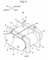
- Figs. 11 and 12 are diagrams each illustrating a coil component unit 100 formed by making plural (for example, two) coil components 40 into a unit.
- Fig. 11 is a perspective view
- Fig. 12 is a sectional plan view.
- the directions of forward, backward, left, and right are shown in each drawing. These directions are used only to illustrate the structure of the coil component unit 100, and do not necessarily correspond to the positional relationships of the coil component unit 100 during manufacturing or when in use.
- a flange portion 25 (see Figs. 11 and 12 ) of the bobbin 20 is not illustrated.
- the bobbin 20 includes a pair of flange portions 25 each provided on both ends of the bobbin body 20a in the axial direction.
- the flange portion 25 is formed into a rectangular shape such as a square shape.
- the longitudinal dimension of the core 30 is longer than that of the bobbin 20, and the end portion of the core 30 protrudes from each end of the bobbin 20.
- the two coil components 40 of the coil component unit 100 are arranged in parallel so that the axial directions of bobbin bodies 20a of these coil components 40 extend in parallel to each other.
- a flat plate-like partitioning plate 80 is disposed between the two coil components 40.
- both ends of the partitioning plate 80 are each provided with a cutout-shaped portion 80a having a shape obtained by cutting out a rectangular-shaped portion from the partitioning plate 80.
- a flat plate-like spacer 50 is disposed at both ends of the coil component 40 in the axial direction of the bobbin body 20a.
- a holding member 60 is disposed at positions located outside of the spacer 50 in the axial direction of the bobbin body 20a (at a position located in front of the forward-side spacer 50 in Fig. 12 and at a position located behind the backward-side spacer 50 in Fig. 12 ).
- the coil component unit 100 includes a pair of spacers 50 and a pair of holding members 60.
- Each of the holding members 60 and the spacers 50 is used to fix both of the two coil components 40 of the coil component unit 100.
- the spacers 50 and the holding members 60 each have an insertion hole 50a and an insertion hole 60a, respectively, formed therein.
- a bolt 71 is inserted into the insertion hole 50a and the insertion hole 60a of each of the spacers 50 and the holding members 60, respectively, located at both ends of the coil components 40 and also into the hollow portion 30b of the core 30.
- a nut 72 is tightened at the tip end side of the bolt 71.
- both ends of the core 30 are sandwiched by the pair of holding members 60 via the spacers 50, respectively.
- the spacer 50 on one side and a holding member 60 adjacent to this spacer 50 are disposed so as to penetrate through a plate surface of the partitioning plate 80 through the cutout-shaped portion 80a on one side (penetrate in the right and left direction in Fig. 11 and Fig. 12 ).
- the spacer 50 on the other side and a holding member 60 adjacent to this spacer 50 are disposed so as to penetrate through a plate surface of the partitioning plate 80 through the cutout-shaped portion 80a on the other side (penetrate in the right and left direction in Fig. 11 and Fig. 12 ).
- a terminal portion 15 for external connection is provided at the outwardly extending pieces 13 at both ends of the edgewise coil 10 of each of the coil components 40.
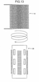
- the coil component 40 according to this exemplary embodiment can be manufactured by screwing a bobbin 20 to a fixed edgewise coil 10 as illustrated, for example, in Fig. 13 , and inserting a core 30 into the bobbin 20.
- the method for manufacturing a coil component according to this example is a method for manufacturing the coil component 40 by winding the edgewise coil 10 around the bobbin 20.
- This method includes: preparing the bobbin 20, which includes: the tubular bobbin body 20a; and the plurality of position-limiting protruding portions arranged in the plurality of portions on the outer peripheral surface of the bobbin body 20a and limiting the position of each winding portion 11 of the edgewise coil 10 in the axial direction of the bobbin body 20a.
- the plurality of position-limiting protruding portions include a first position-limiting protruding portion and a second position-limiting protruding portion, which are disposed at positions different from each other in the axial direction of the bobbin body 20a.
- the method further includes winding the edgewise coil 10 around the bobbin 20 by screwing the bobbin 20 and the edgewise coil 10 with each other, in a manner such that: the edgewise coil 10 includes a first winding portion that is in pressure contact with the first position-limiting protruding portion toward the second position-limiting protruding portion and a second winding portion that is in pressure contact with the second position-limiting protruding portion toward the first position-limiting protruding portion; and the edgewise coil 10 is in a state of space winding in which respective winding portions 11 from the first winding portion and the second winding portion are spaced apart from each other in the axial direction of the bobbin body 20a.
- the edgewise coil 10 extends in the axial direction of the bobbin body 20a due to drag that the winding portions 11 of the edgewise coil 10 receives from the plural position-limiting protruding portions.
- the first winding portion of the edgewise coil 10 is brought into pressure contact with the first position-limiting protruding portion toward the second position-limiting protruding portion
- the second winding portion of the edgewise coil 10 is brought into pressure contact with the second position-limiting protruding portion toward the first position-limiting protruding portion.
- the winding the edgewise coil 10 around the bobbin 20 is performed while the edgewise coil 10 is being caused to extend in the axial direction of the bobbin body 20a using drag that each of the winding portions 11 of the edgewise coil 10 receives from the plurality of position-limiting protruding portions.
- the edgewise coil 10 Before the edgewise coil 10 is screwed with the bobbin 20, the edgewise coil 10 may be tightly wound in a manner such that adjacent winding portions 11 are in close contact with each other.
- these spaces between winding portions 11 can be equalized by limiting positions of the winding portions 11 using the plural position-limiting protruding portions arranged at equal intervals in the axial direction of the bobbin body 20a.
- the first winding portion of the edgewise coil 10 is in pressure contact with the first position-limiting protruding portion toward the second position-limiting protruding portion
- the second winding portion of the edgewise coil 10 is in pressure contact with the second position-limiting protruding portion toward the first position-limiting protruding portion.
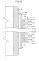
- a coil component according to the second exemplary embodiment is different from the coil component 40 according to the first exemplary embodiment in that the core 30 (core body 30a) is formed into a cylindrical column shape (rather than the tubular shape), and in other points, is configured in a similar manner to the coil component 40 according to the first exemplary embodiment.
Description
- The present invention relates to coil components.
- Document
JP 2006-120767 - This coil component is manufactured in the following manner.
- First, the core is inserted into the coil in a state where the diameter of the coil is increased by twisting it in a radially expanding direction.
- Then, twisting of the coil is released to make the diameter of the coil elastically return to the original diameter. At this time, each protruding portion of the core is arranged between individual winding portions of the coil. In this manner, the coil is wound around the outer periphery of the core.
- In this way, changes in positions of each of the winding portions are limited in the axial direction of the coil by the plural protruding portions.
- According to document
JP H08-264338 - Document
JP 2006-147927 - In document
US 2004/0196128 A1 , there is disclosed an electrical reactor assembly and a method of assembly. The reactor is formed from a combination of a magnetic T-core and a pair of magnetic L-cores. A plurality of comb-like separators is placed over a vertical portion of the T-core. A wire, with a rectangular cross-section, is wound about the vertical portion of the T-core thereby forming a coil. The comb-like separators electrically isolate the wire from adjacent windings and the T-core. The L-cores are attached to the T-core such that they flank two sides of the coil. A plurality of taps is formed on a side of the coil that is not flanked by one of the L-cores. The taps are formed by extending individual windings further from the T-core than other common windings. A hole is formed through the rectangular wire at the taps to provide a secure electrical connection to the wire. - According to the present invention, there is provided a coil component, which includes:
- an edgewise coil; and
- a bobbin around which the edgewise coil is wound, in which
- the bobbin includes:
- a tubular bobbin body; and
- a plurality of position-limiting protruding portions arranged in a plurality of portions on an outer peripheral surface of the bobbin body and limiting a position of a winding portion of the edgewise coil in an axial direction of the bobbin body, the plurality of position limiting protruding portions being discontinuous and spaced-apart from each other,
- the plurality of position-limiting protruding portions of each portion of the plurality of portions including a first position-limiting protruding portion and a second position-limiting protruding portion that are disposed at positions different from each other in the axial direction of the bobbin body,
- wherein the edgewise coil includes:
- a first winding portion that is in pressure contact with the first position-limiting protruding portion of each portion of the plurality of portions toward the second position-limiting protruding portion of each portion of the plurality of portions; and
- a second winding portion that is in pressure contact with the second position-limiting protruding portion of each portion of the plurality of portions toward the respective first position-limiting protruding portion, and
- the edgewise coil is in a state of space winding in which respective winding portions from the first winding portion to the second winding portion are spaced apart from each other in the axial direction of the bobbin body, wherein the plurality of position-limiting protruding portions are arranged along a spirally shaped path.
- According to the present invention, the edgewise coil includes the first winding portion that is in pressure contact with the first position-limiting protruding portion toward the second position-limiting protruding portion and the second winding portion that is in pressure contact with the second position-limiting protruding portion toward the first position-limiting protruding portion. In addition, the edgewise coil is in the state of space winding where respective winding portions from the first winding portion to the second winding portion are spaced apart from each other in the axial direction of the bobbin body. With such a structure, it is possible to stably assemble the edgewise coil to the bobbin, and stably maintain the positions of the winding portions of the coil.
-
-
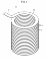
Fig. 1 is a perspective view illustrating a coil that a coil component according to the first exemplary embodiment has. -
Fig. 2 is a perspective view illustrating a bobbin that the coil component according to the first exemplary embodiment has. -
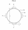
Fig. 3 is a plan view illustrating the bobbin that the coil component according to the first exemplary embodiment has. -
Fig. 4 is an elevation view illustrating the bobbin that the coil component according to the first exemplary embodiment has, showing the shape of the bobbin as viewed in the direction of the arrow A inFig. 2 . -
Fig. 5 is a perspective view illustrating a core that the coil component according to the first exemplary embodiment has. -
Fig. 6 is a front sectional view illustrating the core that the coil component according to the first exemplary embodiment has. -
Fig. 7 is a perspective view illustrating the coil component according to the first exemplary embodiment. -
Fig. 8 is an elevation view illustrating the coil component according to the first exemplary embodiment. -
Fig. 9 is a front sectional view illustrating the coil component according to the first exemplary embodiment. -
Fig. 10 is a front sectional view illustrating a coil component according to a modification example of the first exemplary embodiment. -
Fig. 11 is a perspective view illustrating a coil component unit including the coil component according to the first exemplary embodiment. -
Fig. 12 is a sectional plan view illustrating the coil component unit including the coil component according to the first exemplary embodiment. -
Fig. 13 is an explanatory view illustrating a method for manufacturing the coil component according to the first exemplary embodiment. -
Fig. 14 is a perspective view illustrating a core that a coil component according to a second exemplary embodiment has. -
Fig. 15 is a front sectional view illustrating the core that the coil component according to the second exemplary embodiment has. - However, as a result of studies made by the present inventor, there are rooms for improvement in the technique described in Patent Document 1 in terms of stability of the position of each of the winding portions in the axial direction of the coil.
- The present invention has been made in view of the problem described above, and is to provide a coil component having a structure that can more stably maintain the position of each winding portion of the coil, and also provide a method for manufacturing the coil component.
- The above and other objects, advantages and features of this invention will be more apparent from the following description of certain preferred embodiments taken in conjunction with the accompanying drawings.
- Hereinbelow, exemplary embodiments according to the present invention will be described with reference to the drawings. Note that, in all the drawings, the same reference characters are attached to similar constituent components, and detailed explanation thereof will not be repeated as appropriate.
- First, a
coil component 40 according to this exemplary embodiment will be described with reference toFigs. 1 to 10 . - The
coil component 40 according to this exemplary embodiment includes anedgewise coil 10 and abobbin 20 around which theedgewise coil 10 is wound. Thebobbin 20 includes atubular bobbin body 20a, and a plurality of position-limiting protruding portions (for example, plural position-limitingprotruding portions 21, plural position-limitingprotruding portions 22, plural position-limitingprotruding portions 23, and plural position-limiting protruding portions 24) that are arranged in a plurality of portions on an outer peripheral surface of thebobbin body 20a and limit the position of each windingportion 11 of theedgewise coil 10 in the axial direction of thebobbin body 20a. The plurality of position-limiting protruding portions include a first position-limiting protruding portion (for example, a position-limitingprotruding portion 22b illustrated inFig. 9 and so on) and a second position-limiting protruding portion (for example, a position-limitingprotruding portion 22z illustrated inFig. 9 and so on) that are disposed at positions different from each other in the axial direction of thebobbin body 20a. Theedgewise coil 10 includes a first winding portion (for example, a windingportion 11a illustrated inFig. 9 ) that is in pressure contact with the first position-limiting protruding portion toward the second position-limiting protruding portion, and a second winding portion (for example, a windingportion 11z illustrated inFig. 9 ) that is in pressure contact with the second position-limiting protruding portion toward the first position-limiting protruding portion. Theedgewise coil 10 is in a state of space winding in which respective windingportions 11 from the first winding portion to the second winding portion are spaced apart from each other in the axial direction of thebobbin body 20a. - Here, the space winding represents a way of winding which is also called pitch winding.
- Furthermore, each of the winding
portions 11 is a portion of theedgewise coil 10 that makes one round around thebobbin 20, and theedgewise coil 10 is an assembly of plural windingportions 11 arranged seamlessly in a spiral shape. - In addition, the first position-limiting protruding portion and the second position-limiting protruding portion may be arranged alongside each other in the axial direction of the
bobbin body 20a, or may be arranged alongside each other in a direction intersecting the axial direction. Moreover, the direction of the second position-limiting protruding portion with respect to the first position-limiting protruding portion (the direction in which the first winding portion is in pressure contact with the first position-limiting protruding portion) and the direction of the first position-limiting protruding portion with respect to the second position-limiting protruding portion (the direction in which the second winding portion is in pressure contact with the second position-limiting protruding portion) may be the axial direction of thebobbin body 20a, or may be the direction intersecting this axial direction. - In the case of the
coil component 40 according to this exemplary embodiment, theedgewise coil 10 is in a state of space winding in which respective windingportions 11 from the first winding portion to the second winding portion are spaced apart from each other in the axial direction of thebobbin body 20a. This configuration enables a stray capacity and a proximity effect between windingportions 11 to be reduced, and hence, it is possible to obtain thecoil component 40 with high quality factor, and also possible to reduce the size of thecoil component 40. Furthermore, thecoil component 40 is configured so as to include theedgewise coil 10 using a rectangular wire, and hence, it is possible to reduce the skin effect. In addition, since individual windingportions 11 are space apart from each other, it is possible to achieve a favorable heat dissipation property. - Furthermore, the first winding portion of the
edgewise coil 10 is in pressure contact with the first position-limiting protruding portion toward the second position-limiting protruding portion, and at the same time, the second winding portion of theedgewise coil 10 is in pressure contact with the second position-limiting protruding portion toward the first position-limiting protruding portion. With this configuration, it is possible to stably determine the positions of the first winding portion and the second winding portion with respect to the first position-limiting protruding portion and the second position-limiting protruding portion, respectively. Thus, it is possible to more stably maintain the position of each of the windingportions 11 of theedgewise coil 10. - The
coil component 40 according to this exemplary embodiment can be favorably used as a resonance coil for a field coupling non-contact power supply system, can be used at high frequencies (for example, a band of MHz) and with large electric power (the order of kw or higher), and has a structure that has reduced loss. In such a resonance coil, the alternating-current resistance due to stray capacity, proximity effect and core loss causes a large loss. However, in the case of thecoil component 40 according to this exemplary embodiment, the stray capacity and the proximity effect between windingportions 11 can be reduced, so that the alternating-current resistance can be suppressed. In addition, theedgewise coil 10 configured with a rectangular wire is used to increase the surface area of theedgewise coil 10, so that the skin effect can be reduced. Thus, it is possible to obtain a resonance coil having an excellent quality factor. - That is, in the case of the
coil component 40 according to this exemplary embodiment, although inductance is reduce, the capacitance can be largely reduced, and hence, it is possible to obtain sufficient quality factor. Furthermore, theedgewise coil 10 having a favorable heat dissipation property can be obtained. - Below, detailed description will be given.
- As illustrated in
Fig. 1 , theedgewise coil 10 is formed by spirally winding ametal wire 10a, which is a rectangular wire, and has plural windingportions 11. The windingportions 11 each have a winding diameter equivalent to each other. - The
edgewise coil 10 has an outwardly extendingpiece 13 at both ends thereof. - The
edgewise coil 10 may be configured such that, before wound around thebobbin 20, adjacent windingportions 11 may be in contact with each other (for example, theedgewise coil 10 may be tightly wound in a manner such that nospace 12 exists between adjacent winding portions 11). - As illustrated in any of
Figs. 2 to 4 , thebobbin 20 includes atubular bobbin body 20a, and plural position-limiting protruding portions arranged in plural portions on the outer peripheral surface of thebobbin body 20a. - In the case of this exemplary embodiment, the position-limiting protruding portions are arranged in a plurality of portions in the circumferential direction of the
bobbin body 20a (in a direction around the axial center of thebobbin body 20a). - In addition, a plurality of the position-limiting protruding portions are arranged alongside each other along the axial direction of the
bobbin body 20a at each of the plurality of portions in the circumferential direction of thebobbin body 20a. - More specifically, on the outer peripheral surface of the
bobbin body 20a, plural position-limitingprotruding portions 21, plural position-limitingprotruding portions 22, plural position-limiting protruding portions 23 (seeFig. 3 ), and plural position-limitingprotruding portions 24 are arranged. - The plural position-limiting
protruding portions 21 are arranged alongside each other along the axial direction of thebobbin body 20a at one position in the circumferential direction of thebobbin body 20 a. - In a portion positionally shifted by 90 degrees in the circumferential direction of the
bobbin body 20a from the portion where the plural position-limitingprotruding portions 21 are arranged, the plural position-limitingprotruding portions 22 are arranged alongside each other along the axial direction of thebobbin body 20a. - In a portion positionally shifted by 180 degrees in the circumferential direction of the
bobbin body 20a from the portion where the plural position-limitingprotruding portions 21 are arranged, the plural position-limitingprotruding portions 23 are arranged alongside each other along the axial direction of thebobbin body 20a. - In a portion positionally shifted by 180 degrees in the circumferential direction of the
bobbin body 20a from the portion where the plural position-limitingprotruding portions 22 are arranged, the plural position-limitingprotruding portions 24 are arranged alongside each other along the axial direction of thebobbin body 20a. - In this way, plural position-limiting protruding portions are arranged respectively at positions equiangularly spaced apart in the circumferential direction of the
bobbin body 20a. - For example, the number of the position-limiting
protruding portions 21, the number of the position-limitingprotruding portions 22, the number of the position-limitingprotruding portions 23, and the number of the position-limitingprotruding portions 24 are equal to each other. - The
bobbin 20 includes a position-limitingprotruding portion 21a, a position-limitingprotruding portion 21b, a position-limitingprotruding portion 21c, and a position-limitingprotruding portion 21d in the order they appear from the bottom inFig. 4 , each of which serves as the position-limitingprotruding portion 21. - Similarly, the
bobbin 20 includes a position-limitingprotruding portion 22a, a position-limitingprotruding portion 22b, a position-limitingprotruding portion 22c, and a position-limitingprotruding portion 22d in the order they appear from the bottom inFig. 8 , each of which serves as the position-limitingprotruding portion 22. - Similarly, the
bobbin 20 includes a position-limiting protruding portion 23a (not illustrated), a position-limiting protruding portion 23b (not illustrated), a position-limiting protruding portion 23c (not illustrated), and a position-limiting protruding portion 23d (not illustrated) in the order from bottom to top inFig. 8 , each of which serves as the position-limitingprotruding portion 23. Here, the reference characters 23a, 23b, 23c, and 23d are reference characters used for convenience sake and not illustrated in the drawings. - Similarly, the
bobbin 20 includes a position-limitingprotruding portion 24a, a position-limitingprotruding portion 24b, a position-limitingprotruding portion 24c, and a position-limitingprotruding portion 24d in the order they appear from the bottom inFig. 8 , each of which serves as the position-limitingprotruding portion 24. - In addition, the
bobbin 20 includes a position-limitingprotruding portion 22z, a position-limitingprotruding portion 22y, and a position-limitingprotruding portion 22x in the order they appear from the top inFig. 8 , each of which serves as the position-limitingprotruding portion 22. - Furthermore, the
bobbin 20 includes a position-limitingprotruding portion 21z serving as the position-limitingprotruding portion 21 and located at the uppermost position inFig. 8 . - Similarly, the
bobbin 20 includes a position-limiting protruding portion 23z (not illustrated) serving as the position-limitingprotruding portion 23 and located at the uppermost position inFig. 8 . Here, the reference character 23z is a reference character used for convenience sake and not illustrated in the drawings. - Similarly, the
bobbin 20 includes a position-limitingprotruding portion 24z serving as the position-limitingprotruding portion 24 and located at the uppermost position inFig. 8 . - In
Fig. 4 , the position-limitingprotruding portion 22a is disposed at a position higher than the position-limitingprotruding portion 21a; the position-limiting protruding portion 23a (not illustrated) is disposed at a position higher than the position-limitingprotruding portion 22a; the position-limitingprotruding portion 24a is disposed at a position higher than the position-limiting protruding portion 23a; and the position-limitingprotruding portion 21b is disposed at a position higher than the position-limitingprotruding portion 24a. - Here, in the axial direction of the
bobbin body 20a, the distance between the position-limitingprotruding portion 21a and the position-limitingprotruding portion 22a, the distance between the position-limitingprotruding portion 22a and the position-limiting protruding portion 23a, the distance between the position-limiting protruding portion 23a and the position-limitingprotruding portion 24a, and the distance between the position-limitingprotruding portion 24a and the position-limitingprotruding portion 21b are, for example, one quarter of the distance between the position-limitingprotruding portion 21a and the position-limitingprotruding portion 21b. - In addition, the position-limiting
protruding portions 21 are each arranged at equal intervals in the axial direction of thebobbin body 20a. - Similarly, the position-limiting
protruding portions 22 are each arranged at equal intervals in the axial direction of thebobbin body 20a. - Similarly, the position-limiting
protruding portions 23 are each arranged at equal intervals in the axial direction of thebobbin body 20a. - Similarly, the position-limiting
protruding portions 24 are each arranged at equal intervals in the axial direction of thebobbin body 20a. - Furthermore, the distance between adjacent position-limiting
protruding portions 21, the distance between adjacent position-limitingprotruding portions 22, the distance between adjacent position-limitingprotruding portions 23, and the distance between adjacent position-limitingprotruding portions 24 are equal to each other. - Thus, the position-limiting protruding portions of the
bobbin 20 are arranged alongside each other along the spirally shaped path in the following order: the position-limitingprotruding portion 21a, the position-limitingprotruding portion 22a, the position-limiting protruding portion 23a, the position-limitingprotruding portion 24a, the position-limitingprotruding portion 21b, the position-limitingprotruding portion 22b, the position-limiting protruding portion 23b, the position-limitingprotruding portion 24b, the position-limitingprotruding portion 21c, .... - As described above, the plurality of position-limiting protruding portions of the
bobbin 20 are arranged along the spirally shaped path. - In the case of this exemplary embodiment, each of the position-limiting protruding portions is a rib elongated in the circumferential direction of the
bobbin body 20a. That is, the position-limiting protruding portions each have the shape in which the size of each of the position-limiting protruding portions in the circumferential direction of thebobbin body 20a is larger than the size of each of the position-limiting protruding portions in the axial direction of thebobbin body 20a. - More specifically, the position-limiting protruding portions each have a pair of
orthogonal surfaces 26 orthogonal to the axial direction of thebobbin body 20a. That is, inFig. 4 , the surface on the bottom side and the surface on the top side of each of the position-limiting protruding portions each serve as the orthogonal surface 26 (inFig. 4 , the reference character of theorthogonal surface 26 is attached only to the position-limiting protruding portion 2Iz). - As described above, the plural position-limiting protruding portions each have the
orthogonal surfaces 26, each of which is orthogonal to the axial direction of thebobbin body 20a. Theorthogonal surfaces 26 are formed into a flat plane shape. - The shape and the size of each of the position-limiting protruding portions are set, for example, so as to be equivalent to each other.
- In the
bobbin body 20a, for example, one or a plurality ofopenings 20c penetrating the inside and the outside of the bobbinmain body 20a are formed. That is, ahollow portion 20b, which is the inside space of thebobbing body 20a, and the external space of thebobbin body 20a are communicated with each other through each of theopening 20c. - For example, in the circumferential direction of the
bobbin body 20a,plural openings 20c are arranged respectively between the line of the plural position-limitingprotruding portions 21 and the line of the plural position-limitingprotruding portions 22, between the line of the plural position-limitingprotruding portions 22 and the line of the plural position-limitingprotruding portions 23, between the line of the plural position-limitingprotruding portions 23 and the line of the plural position-limitingprotruding portions 24, and between the line of the plural position-limitingprotruding portions 24 and the line of the plural position-limitingprotruding portions 21. - For example, the
entire bobbin 20 including thebobbin body 20a and the plural position-limiting protruding portions (the plural position-limitingprotruding portions 21, the plural position-limitingprotruding portions 22, the plural position-limitingprotruding portions 23, and the plural position-limiting protruding portions 24) is formed integrally using resin or other insulating, non-magnetic material. - In this exemplary embodiment, description is made of an example in which plural position-limiting protruding portions are arranged in each of four portions located in the circumferential direction of the
bobbin body 20a. However, the present invention is not limited to this example. It may be possible that plural position-limiting protruding portions are arranged in each of two or three portions in the circumferential direction of thebobbin body 20a, or it may be possible that plural position-limiting protruding portions are arranged in each of five or more portions in the circumferential direction of thebobbin body 20a. - Furthermore, the present invention is not limited to the example in which position-limiting protruding portions are arranged in each of plural portions in the circumferential direction of the
bobbin body 20a. It may be possible to employ a configuration in which plural position-limiting protruding portions are arranged in only one portion in the circumferential direction of thebobbin body 20a. - In addition, the present invention is not limited to the example in which plural position-limiting protruding portions are arranged alongside each other along the axial direction of the
bobbin body 20a in each of plural portions located in the circumferential direction of thebobbin body 20a. It may be possible to employ a configuration in which one position-limiting protruding portion is disposed in each of plural portions located in the circumferential direction of thebobbin body 20a. - In an example which is not part of the invention, one spirally shaped position-limiting protruding portion (rib) is formed on the outer peripheral surface of the
bobbin body 20a instead of plural position-limiting protruding portions arranged on the out peripheral surface of ) the bobbin body. - As illustrated in
Figs. 5 and6 , in the case of this exemplary embodiment, thecore 30 is comprised of atubular core body 30a. On the inner side of thecore body 30a, a cylindricalhollow portion 30b is formed. - The outer diameter of the
core 30 is smaller than the inner diameter of thebobbin body 20a. - Here, H (see
Fig. 3 ) represents the projection length of the position-limiting protruding portion outward from the outer peripheral surface of thebobbin body 20a in the radial direction ) of thebobbin body 20a (the size of height of the position-limiting protruding portion), and R (seeFig. 3 ) represents the outer diameter of thebobbin body 20a. The inner diameter of theedgewise coil 10 is larger than the outer diameter R of thebobbin body 20a, and preferably, is less than (R + 2H). In addition, it may be possible to set the inner diameter of theedgewise coil 10 to be less than (R + H). By setting the inner diameter of theedgewise coil 10 so as to be less than (R + 2H), it is possible to more reliably engage the windingportions 11 of theedgewise coil 10 with the position-limiting protruding portions. - As illustrated in
Figs. 7 and8 , thecoil component 40 is configured by winding theedgewise coil 10 around thebobbin body 20a and inserting the core 30 into the hollow portion ) 20b of thebobbin 20. - As illustrated in
Fig. 8 , each of the windingportions 11 of theedgewise coil 10 is disposed between position-limiting protruding portions adjacent to each other in the axial direction of thebobbin body 20a. Here, theedgewise coil 10 includes a windingportion 11a, a windingportion 11b, a windingportion 11c, and a windingportion 11d in the order they appear from the bottom inFig. 8 . - Furthermore, the
edgewise coil 10 includes a windingportion 11z, a windingportion 11y, a windingportion 11x, and a windingportion 11w in the order they appear from the top inFig. 8 . - Of these winding portions, the winding
portion 11a passes through, for example, between the position-limitingprotruding portion 21a and the position-limitingprotruding portion 21b, between the position-limitingprotruding portion 22a and the position-limitingprotruding portion 22b, and between the position-limiting protruding portion 23a (not illustrated) and the position-limiting protruding portion 23b (not illustrated), and then, reaches a portion between the position-limitingprotruding portion 24a and the position-limitingprotruding portion 24b. - Similarly, the winding
portion 11b passes through between the position-limitingprotruding portion 21b and the position-limitingprotruding portion 21c, between the position-limitingprotruding portion 22b and the position-limitingprotruding portion 22c, and between the position-limiting protruding portion 23b (not illustrated) and the position-limiting protruding portion 23c (not illustrated), and then, reaches a portion between the position-limitingprotruding portion 24b and the position-limitingprotruding portion 24c. - Similarly, the winding
portion 11c passes through between the position-limitingprotruding portion 21c and the position-limitingprotruding portion 21d, between the position-limitingprotruding portion 22c and the position-limitingprotruding portion 22d, and between the position-limiting protruding portion 23c (not illustrated) and the position-limiting protruding portion 23d (not illustrated), and then, reaches a portion between the position-limitingprotruding portion 24c and the position-limitingprotruding portion 24d. - Other winding
portions 11 of theedgewise coil 10 similarly pass sequentially through between position-limiting protruding portions adjacent to each other in the axial direction of thebobbin 20. - Thus, the path of the
wire 10a forming theedgewise coil 10 is limited to the spirally shaped path by the plural position-limiting protruding portions of thebobbin 20. - In addition, a
space 12 exists between windingportions 11 adjacent to each other of theedgewise coil 10. In other words, theedgewise coil 10 is in a state of space winding (in a state of pitch winding). - More specifically, for example, as illustrated in
Fig. 9 , the windingportion 11a of theedgewise coil 10 is in pressure contact with the position-limitingprotruding portion 22b toward the top side inFig. 9 (in other words, toward the position-limitingprotruding portion 22z). Meanwhile, the windingportion 11z of theedgewise coil 10 is in pressure contact with the position-limitingprotruding portion 22z toward the bottom side inFig. 9 (in other words, toward the position-limitingprotruding portion 22b). - In addition, the winding
portion 11a of theedgewise coil 10 is in pressure contact with the position-limitingprotruding portion 21b towards the position-limitingprotruding portion 21z, although no detailed illustration is given. Meanwhile, the windingportion 11z of theedgewise coil 10 is in pressure contact with the position-limitingprotruding portion 21z toward the position-limitingprotruding portion 21b. - Furthermore, although no illustration is given, the winding
portion 11a of theedgewise coil 10 is in pressure contact with the position-limiting protruding portion 23b toward the position-limiting protruding portion 23z. Meanwhile, the windingportion 11z of theedgewise coil 10 is in pressure contact with the position-limiting protruding portion 23z toward the position-limiting protruding portion 23b. - Moreover, although no detailed illustration is given, the winding
portion 11a of theedgewise coil 10 is in pressure contact with the position-limitingprotruding portion 24b toward the position-limitingprotruding portion 24z. Meanwhile, the windingportion 11z of theedgewise coil 10 is in pressure contact with the position-limitingprotruding portion 24z toward the position-limitingprotruding portion 24b. - As described above, the plural position-limiting protruding portions include the first position-limiting protruding portion (for example, the position-limiting
protruding portion protruding portion bobbin body 20a. In addition, theedgewise coil 10 includes the first winding portion (for example, the windingportion 11a) that is in pressure contact with the first position-limiting protruding portion toward the second position-limiting protruding portion, and the second winding portion (for example, the windingportion 11z) that is in pressure contact with the second position-limiting protruding portion toward the first position-limiting protruding portion. - More specifically, the first winding portion (for example, the winding
portion 11a) is in pressure contact with the orthogonal surface 26 (in particular, the surface on the bottom side of the first position-limiting protruding portion inFigs. 8 and9 ) of the first position-limiting protruding portion (for example, the position-limitingprotruding portion portion 11z) is in pressure contact with the orthogonal surface 26 (in particular, the surface on the top side of the second position-limiting protruding portion inFigs. 8 and9 ) of the second position-limiting protruding portion. - Thus, the first winding portion and the second winding portion are substantially in surface contact with the first position-limiting protruding portion and the second position-limiting protruding portion, respectively.
- This configuration more reliably reduces the positional displacement of the first winding portion and the second winding portion relative to the first position-limiting protruding portion and the second position-limiting protruding portion, respectively.
- In addition, the winding portions 11 (for example, the winding
portion Fig. 9 ) other than the first winding portion (for example, the windingportion 11a) and the second winding portion (for example, the windingportion 11z) are disposed, for example, between position-limitingprotruding portions 21 adjacent to each other in the axial direction of thebobbin body 20a, between position-limitingprotruding portions 22 adjacent to each other in the axial direction of thebobbin body 20a, between position-limitingprotruding portions 23 adjacent to each other in the axial direction of thebobbin body 20a, and between position-limitingprotruding portions 24 adjacent to each other in the axial direction of thebobbin body 20a, respectively, and are not in contact with any of position-limiting protruding portions. - With this configuration, winding
portions 11 from the first winding portion (for example, the windingportion 11a) to the second winding portion (for example, the windingportion 11z) are arranged equally (substantially at equal intervals) in the axial direction of thebobbin body 20a. - However, it may be possible that part of the winding
portions 11 other than the first winding portion (for example, the windingportion 11a) and the second winding portion (for example, the windingportion 11z) is in contact with any of position-limiting protruding portions. - In the example illustrated in
Figs. 8 and9 , surplus position-limitingprotruding portions protruding portions bobbin body 20a in the axial direction. However, these surplus position-limiting protruding portions may not exist. - In addition, surplus position-limiting protruding portions may exist on both sides of the
bobbin body 20a in the axial direction. - Description has been made with reference to
Fig. 9 of an example in which the winding portions 11 (windingportions edgewise coil 10 are each in pressure contact with the position-limiting protruding portion. However, it may be possible that asurplus winding portion 11 exists on both sides or one side of theedgewise coil 10, and a windingportion 11 that is not an end portion of theedgewise coil 10 is in pressure contact with a position-limiting protruding portion. - That is, for example, as illustrated in
Fig. 10 , it may be possible that the windingportion 11b is in pressure contact with the position-limitingprotruding portion 22a toward the position-limitingprotruding portion 22z, and the windingportion 11y is in pressure contact with the position-limitingprotruding portion 22z toward the position-limitingprotruding portion 22a. In this case, the windingportion 11b serves as the first winding portion, and the windingportion 11y serves as the second winding portion. In addition, the position-limitingprotruding portion 22a serves as the first position-limiting protruding portion, and the position-limitingprotruding portion 22z serves as the second position-limiting protruding portion. - In this case, a
surplus winding portion 11 may be tightly wound in a manner such that the excess windingportion 11 is in close contact with an adjacent windingportion 11. At least, in the axial direction of thebobbin body 20a, the space between asurplus winding portion 11 and a windingportion 11 adjacent to thesurplus winding portion 11 is narrower than each of the spaces between windingportions 11 adjacent to each other of the winding portions from the first winding portion to the second winding portion. -
Figs. 11 and12 are diagrams each illustrating acoil component unit 100 formed by making plural (for example, two)coil components 40 into a unit.Fig. 11 is a perspective view andFig. 12 is a sectional plan view. As for the positional relationship of thecoil component unit 100 in each ofFigs. 11 and12 , the directions of forward, backward, left, and right are shown in each drawing. These directions are used only to illustrate the structure of thecoil component unit 100, and do not necessarily correspond to the positional relationships of thecoil component unit 100 during manufacturing or when in use. - Here, in
Figs. 2 to 4 andFigs. 7 to 10 , a flange portion 25 (seeFigs. 11 and12 ) of thebobbin 20 is not illustrated. However, thebobbin 20 includes a pair offlange portions 25 each provided on both ends of thebobbin body 20a in the axial direction. Theflange portion 25 is formed into a rectangular shape such as a square shape. - In addition, as illustrated in
Figs. 7 ,8 , and12 , in the axial direction of thebobbin body 20a, the longitudinal dimension of thecore 30 is longer than that of thebobbin 20, and the end portion of the core 30 protrudes from each end of thebobbin 20. - Here, the two
coil components 40 of thecoil component unit 100 are arranged in parallel so that the axial directions ofbobbin bodies 20a of thesecoil components 40 extend in parallel to each other. - In addition, a flat plate-
like partitioning plate 80 is disposed between the twocoil components 40. - In the axial direction of the
bobbin body 20a, both ends of thepartitioning plate 80 are each provided with a cutout-shapedportion 80a having a shape obtained by cutting out a rectangular-shaped portion from thepartitioning plate 80. - As illustrated in
Fig. 12 , a flat plate-like spacer 50 is disposed at both ends of thecoil component 40 in the axial direction of thebobbin body 20a. - In addition, a holding
member 60 is disposed at positions located outside of thespacer 50 in the axial direction of thebobbin body 20a (at a position located in front of the forward-side spacer 50 inFig. 12 and at a position located behind the backward-side spacer 50 inFig. 12 ). - That is, the
coil component unit 100 includes a pair ofspacers 50 and a pair of holdingmembers 60. - Each of the holding
members 60 and thespacers 50 is used to fix both of the twocoil components 40 of thecoil component unit 100. - The
spacers 50 and the holdingmembers 60 each have aninsertion hole 50a and aninsertion hole 60a, respectively, formed therein. Abolt 71 is inserted into theinsertion hole 50a and theinsertion hole 60a of each of thespacers 50 and the holdingmembers 60, respectively, located at both ends of thecoil components 40 and also into thehollow portion 30b of thecore 30. Anut 72 is tightened at the tip end side of thebolt 71. With this configuration, a pair of holdingmembers 60, a pair ofspacers 50, and thecoil components 40 are fixed to each other with afastening member 70 including thebolt 71 and thenut 72. - That is, by fastening the
bolt 71 and thenut 72 together, both ends of the core 30 are sandwiched by the pair of holdingmembers 60 via thespacers 50, respectively. - The
spacer 50 on one side and a holdingmember 60 adjacent to thisspacer 50 are disposed so as to penetrate through a plate surface of thepartitioning plate 80 through the cutout-shapedportion 80a on one side (penetrate in the right and left direction inFig. 11 andFig. 12 ). - Similarly, the
spacer 50 on the other side and a holdingmember 60 adjacent to thisspacer 50 are disposed so as to penetrate through a plate surface of thepartitioning plate 80 through the cutout-shapedportion 80a on the other side (penetrate in the right and left direction inFig. 11 andFig. 12 ). - In addition, a
terminal portion 15 for external connection is provided at the outwardly extendingpieces 13 at both ends of theedgewise coil 10 of each of thecoil components 40. - The
coil component 40 according to this exemplary embodiment can be manufactured by screwing abobbin 20 to a fixededgewise coil 10 as illustrated, for example, inFig. 13 , and inserting a core 30 into thebobbin 20. - That is, the method for manufacturing a coil component according to this example is a method for manufacturing the
coil component 40 by winding theedgewise coil 10 around thebobbin 20. This method includes: preparing thebobbin 20, which includes: thetubular bobbin body 20a; and the plurality of position-limiting protruding portions arranged in the plurality of portions on the outer peripheral surface of thebobbin body 20a and limiting the position of each windingportion 11 of theedgewise coil 10 in the axial direction of thebobbin body 20a. The plurality of position-limiting protruding portions include a first position-limiting protruding portion and a second position-limiting protruding portion, which are disposed at positions different from each other in the axial direction of thebobbin body 20a. The method further includes winding theedgewise coil 10 around thebobbin 20 by screwing thebobbin 20 and theedgewise coil 10 with each other, in a manner such that: theedgewise coil 10 includes a first winding portion that is in pressure contact with the first position-limiting protruding portion toward the second position-limiting protruding portion and a second winding portion that is in pressure contact with the second position-limiting protruding portion toward the first position-limiting protruding portion; and theedgewise coil 10 is in a state of space winding in which respective windingportions 11 from the first winding portion and the second winding portion are spaced apart from each other in the axial direction of thebobbin body 20a. - Here, when the
bobbin 20 and theedgewise coil 10 are screwed with each other, theedgewise coil 10 extends in the axial direction of thebobbin body 20a due to drag that the windingportions 11 of theedgewise coil 10 receives from the plural position-limiting protruding portions. As a result, the first winding portion of theedgewise coil 10 is brought into pressure contact with the first position-limiting protruding portion toward the second position-limiting protruding portion, and the second winding portion of theedgewise coil 10 is brought into pressure contact with the second position-limiting protruding portion toward the first position-limiting protruding portion. - As described above, the winding the
edgewise coil 10 around thebobbin 20 is performed while theedgewise coil 10 is being caused to extend in the axial direction of thebobbin body 20a using drag that each of the windingportions 11 of theedgewise coil 10 receives from the plurality of position-limiting protruding portions. - Before the
edgewise coil 10 is screwed with thebobbin 20, theedgewise coil 10 may be tightly wound in a manner such that adjacent windingportions 11 are in close contact with each other. - In addition, if there are variations in spaces between winding
portions 11 of theedgewise coil 10 before theedgewise coil 10 is screwed with thebobbin 20, these spaces between windingportions 11 can be equalized by limiting positions of the windingportions 11 using the plural position-limiting protruding portions arranged at equal intervals in the axial direction of thebobbin body 20a. - According to the first exemplary embodiment as described above, the first winding portion of the
edgewise coil 10 is in pressure contact with the first position-limiting protruding portion toward the second position-limiting protruding portion, and the second winding portion of theedgewise coil 10 is in pressure contact with the second position-limiting protruding portion toward the first position-limiting protruding portion. With this configuration, it is possible to stably determine the positions of the first winding portion and the second winding portion with respect to the first position-limiting protruding portion and the second position-limiting protruding portion, respectively. Thus, it is possible to more stably maintain the positions of each of the windingportions 11 of theedgewise coil 10, and it is possible to more reliably achieve thecoil component 40 having a high quality factor. - As illustrated in
Figs. 14 and15 , a coil component according to the second exemplary embodiment is different from thecoil component 40 according to the first exemplary embodiment in that the core 30 (core body 30a) is formed into a cylindrical column shape (rather than the tubular shape), and in other points, is configured in a similar manner to thecoil component 40 according to the first exemplary embodiment. - These are descriptions of each of the exemplary embodiments with reference to the drawings. However, these are merely examples of the present invention, and it may be possible to employ various configurations other than those described above. In addition, it may be possible to combine the exemplary embodiments described above as appropriate without departing from the present invention.
- This application is based on
Japanese Patent Application No. 2017-12701, filed on January 27, 2017
Claims (4)
- A coil component (40), comprising:an edgewise coil (10); anda bobbin (20) around which the edgewise coil (10) is wound, whereinthe bobbin (20) comprises:a tubular bobbin body (20a); anda plurality of position-limiting protruding portions arranged in a plurality of portions (21, 22, 23, 24) on an outer peripheral surface of the bobbin body (20a) and limiting a position of a winding portion (11) of the edgewise coil (10) in an axial direction of the bobbin body (20a),the plurality of position limiting protruding portions being discontinuous and spaced-apart from each other;the plurality of position-limiting protruding portions of each portion (21; 22; 23; 24) of the plurality of portions (21, 22, 23, 24) including a first position-limiting protruding portion (21a, 22a, 24a) and a second position-limiting protruding portion (21z, 22z, 24z) that are disposed at positions different from each other in the axial direction of the bobbin body (20a),wherein the edgewise coil (10) includes:a first winding portion (11a) that is in pressure contact with the first position-limiting protruding portion (21a, 22a, 24a) of each portion (21; 22; 23; 24) of the plurality of portions (21, 22, 23, 24) toward the second position-limiting protruding portion (21z, 22, 24z) of each portion (21; 22; 23; 24) of the plurality of portions (21, 22, 23, 24); anda second winding portion (11z) that is in pressure contact with the second position-limiting protruding portion (21z, 22z, 24z) of each portion (21; 22; 23; 24) of the plurality of portions (21, 22, 23, 24) toward the respective first position-limiting protruding portion (21a; 22a; 24a), andthe edgewise coil (10) is in a state of space winding in which respective winding portions (11) from the first winding portion (11a) to the second winding portion (11z) are spaced apart from each other in the axial direction of the bobbin body (20a) wherein the plurality of portions (21, 22, 23, 24) is arranged in a circumferential direction of the bobbin body (20a),wherein said position-limiting protruding portions are arranged alongside each other along the axial direction of the bobbin body (20a) at each of the plurality of portions (21, 22, 23, 24) in the circumferential direction of the bobbin body (20a), andwherein the plurality of position-limiting protruding portions are arranged along a spirally shaped path.
- The coil component (40) according to claim 1, whereineach of the plurality of position-limiting protruding portions has an orthogonal surface (26) orthogonal to the axial direction of the bobbin body (20a), andthe first winding portion (11a) is in pressure contact with the orthogonal surface (26) of the first position-limiting protruding portion (21a; 22a; 24a), while the second winding portion (11z) is in pressure contact with the orthogonal surface (26) of the second position-limiting protruding portion (21z, 22z, 24z).
- The coil component (40) according to claim 1 or 2, wherein the inner diameter of the edgewise coil (10) is larger than the outer diameter of the bobbin body (20a).
- The coil component (40) according to any one of claims 1 to 3, wherein in the bobbin body (20a), one or a plurality of openings (20c) penetrating the inside and the outside of the bobbin body (20a) are formed.
Applications Claiming Priority (1)
| Application Number | Priority Date | Filing Date | Title |
|---|---|---|---|
| JP2017012701A JP6888309B2 (en) | 2017-01-27 | 2017-01-27 | Coil parts and manufacturing method of coil parts |
Publications (2)
| Publication Number | Publication Date |
|---|---|
| EP3355322A1 EP3355322A1 (en) | 2018-08-01 |
| EP3355322B1 true EP3355322B1 (en) | 2022-03-09 |
Family
ID=61027472
Family Applications (1)
| Application Number | Title | Priority Date | Filing Date |
|---|---|---|---|
| EP18152911.6A Active EP3355322B1 (en) | 2017-01-27 | 2018-01-23 | Coil component |
Country Status (4)
| Country | Link |
|---|---|
| US (1) | US10643786B2 (en) |
| EP (1) | EP3355322B1 (en) |
| JP (1) | JP6888309B2 (en) |
| CN (1) | CN108364771B (en) |
Family Cites Families (12)
| Publication number | Priority date | Publication date | Assignee | Title |
|---|---|---|---|---|
| JPS4624784Y1 (en) * | 1968-09-28 | 1971-08-26 | ||
| JPH08264338A (en) * | 1995-03-28 | 1996-10-11 | Matsushita Electric Works Ltd | Electromagnetic device |
| US6954131B2 (en) * | 2003-04-02 | 2005-10-11 | Illinois Tool Works Inc. | Electrical reactor assembly having center taps |
| JP4356928B2 (en) * | 2004-01-30 | 2009-11-04 | Tdk株式会社 | Folding coil, folding coil bobbin, and method of manufacturing the folding coil |
| JP2006120767A (en) * | 2004-10-20 | 2006-05-11 | Sumitomo Electric Ind Ltd | Reactor and method of manufacturing same |
| JP4622475B2 (en) * | 2004-11-22 | 2011-02-02 | ウシオ電機株式会社 | Trance |
| US7256673B2 (en) * | 2005-01-31 | 2007-08-14 | Tdk Corporation | Coil assembly including common-mode choke coil |
| KR100777603B1 (en) * | 2006-11-20 | 2007-11-21 | 주식회사 세림테크 | Transbobbin designated to generating high voltage |
| KR101085665B1 (en) * | 2009-02-26 | 2011-11-22 | 삼성전기주식회사 | Transformer |
| JP5381673B2 (en) * | 2009-12-14 | 2014-01-08 | 住友電気工業株式会社 | Reactor |
| JP2014082266A (en) * | 2012-10-15 | 2014-05-08 | Auto Network Gijutsu Kenkyusho:Kk | Coil |
| JP2015201491A (en) * | 2014-04-04 | 2015-11-12 | トヨタ自動車株式会社 | Reactor with cooler |
-
2017
- 2017-01-27 JP JP2017012701A patent/JP6888309B2/en active Active
- 2017-11-30 CN CN201711236762.1A patent/CN108364771B/en active Active
- 2017-12-13 US US15/840,148 patent/US10643786B2/en active Active
-
2018
- 2018-01-23 EP EP18152911.6A patent/EP3355322B1/en active Active
Also Published As
| Publication number | Publication date |
|---|---|
| EP3355322A1 (en) | 2018-08-01 |
| JP2018121003A (en) | 2018-08-02 |
| CN108364771A (en) | 2018-08-03 |
| US10643786B2 (en) | 2020-05-05 |
| CN108364771B (en) | 2022-09-13 |
| JP6888309B2 (en) | 2021-06-16 |
| US20180218831A1 (en) | 2018-08-02 |
Similar Documents
| Publication | Publication Date | Title |
|---|---|---|
| EP1547103B1 (en) | Coil form | |
| JP6380745B2 (en) | Trance | |
| KR102016225B1 (en) | Transformer | |
| US7656261B2 (en) | Integrated magnetic device and conductive structure thereof | |
| US8471663B2 (en) | Combined winding structure and magnetic device | |
| JPH08264338A (en) | Electromagnetic device | |
| US20220130602A1 (en) | Transformer And Method For Manufacturing Transformer | |
| US9793044B2 (en) | Coil device and method for manufacturing the same | |
| EP3355322B1 (en) | Coil component | |
| US20210065930A1 (en) | Conducting wire and coil member | |
| US20040113739A1 (en) | Low profile transformer | |
| KR101656013B1 (en) | Coil component | |
| US20170117090A1 (en) | Energy storage apparatus | |
| US8970335B2 (en) | Coil form for forming an inductive element | |
| CN210722717U (en) | Flat transformer | |
| US9082544B2 (en) | Bobbin and coil component | |
| JP2008270347A (en) | Transformer | |
| US10672553B2 (en) | High voltage high frequency transformer | |
| JP2015207577A (en) | coil | |
| CN114078625A (en) | Transformer device |
Legal Events
| Date | Code | Title | Description |
|---|---|---|---|
| PUAI | Public reference made under article 153(3) epc to a published international application that has entered the european phase |
Free format text: ORIGINAL CODE: 0009012 |
|
| STAA | Information on the status of an ep patent application or granted ep patent |
Free format text: STATUS: THE APPLICATION HAS BEEN PUBLISHED |
|
| AK | Designated contracting states |
Kind code of ref document: A1 Designated state(s): AL AT BE BG CH CY CZ DE DK EE ES FI FR GB GR HR HU IE IS IT LI LT LU LV MC MK MT NL NO PL PT RO RS SE SI SK SM TR |
|
| AX | Request for extension of the european patent |
Extension state: BA ME |
|
| STAA | Information on the status of an ep patent application or granted ep patent |
Free format text: STATUS: REQUEST FOR EXAMINATION WAS MADE |
|
| 17P | Request for examination filed |
Effective date: 20190131 |
|
| RBV | Designated contracting states (corrected) |
Designated state(s): AL AT BE BG CH CY CZ DE DK EE ES FI FR GB GR HR HU IE IS IT LI LT LU LV MC MK MT NL NO PL PT RO RS SE SI SK SM TR |
|
| STAA | Information on the status of an ep patent application or granted ep patent |
Free format text: STATUS: REQUEST FOR EXAMINATION WAS MADE |
|
| STAA | Information on the status of an ep patent application or granted ep patent |
Free format text: STATUS: EXAMINATION IS IN PROGRESS |
|
| 17Q | First examination report despatched |
Effective date: 20210201 |
|
| RAP3 | Party data changed (applicant data changed or rights of an application transferred) |
Owner name: SUMIDA CORPORATION |
|
| RIC1 | Information provided on ipc code assigned before grant |
Ipc: H01F 27/00 20060101ALN20210923BHEP Ipc: H01F 41/061 20160101ALI20210923BHEP Ipc: H01F 27/32 20060101ALI20210923BHEP Ipc: H01F 5/02 20060101AFI20210923BHEP |
|
| GRAP | Despatch of communication of intention to grant a patent |
Free format text: ORIGINAL CODE: EPIDOSNIGR1 |
|
| STAA | Information on the status of an ep patent application or granted ep patent |
Free format text: STATUS: GRANT OF PATENT IS INTENDED |
|
| RIC1 | Information provided on ipc code assigned before grant |
Ipc: H01F 27/00 20060101ALN20211022BHEP Ipc: H01F 41/061 20160101ALI20211022BHEP Ipc: H01F 27/32 20060101ALI20211022BHEP Ipc: H01F 5/02 20060101AFI20211022BHEP |
|
| INTG | Intention to grant announced |
Effective date: 20211112 |
|
| GRAS | Grant fee paid |
Free format text: ORIGINAL CODE: EPIDOSNIGR3 |
|
| GRAA | (expected) grant |
Free format text: ORIGINAL CODE: 0009210 |
|
| STAA | Information on the status of an ep patent application or granted ep patent |
Free format text: STATUS: THE PATENT HAS BEEN GRANTED |
|
| AK | Designated contracting states |
Kind code of ref document: B1 Designated state(s): AL AT BE BG CH CY CZ DE DK EE ES FI FR GB GR HR HU IE IS IT LI LT LU LV MC MK MT NL NO PL PT RO RS SE SI SK SM TR |
|
| REG | Reference to a national code |
Ref country code: CH Ref legal event code: EP Ref country code: AT Ref legal event code: REF Ref document number: 1474833 Country of ref document: AT Kind code of ref document: T Effective date: 20220315 |
|
| REG | Reference to a national code |
Ref country code: DE Ref legal event code: R096 Ref document number: 602018031834 Country of ref document: DE |
|
| REG | Reference to a national code |
Ref country code: IE Ref legal event code: FG4D |
|
| REG | Reference to a national code |
Ref country code: LT Ref legal event code: MG9D |
|
| REG | Reference to a national code |
Ref country code: NL Ref legal event code: MP Effective date: 20220309 |
|
| PG25 | Lapsed in a contracting state [announced via postgrant information from national office to epo] |
Ref country code: SE Free format text: LAPSE BECAUSE OF FAILURE TO SUBMIT A TRANSLATION OF THE DESCRIPTION OR TO PAY THE FEE WITHIN THE PRESCRIBED TIME-LIMIT Effective date: 20220309 Ref country code: RS Free format text: LAPSE BECAUSE OF FAILURE TO SUBMIT A TRANSLATION OF THE DESCRIPTION OR TO PAY THE FEE WITHIN THE PRESCRIBED TIME-LIMIT Effective date: 20220309 Ref country code: NO Free format text: LAPSE BECAUSE OF FAILURE TO SUBMIT A TRANSLATION OF THE DESCRIPTION OR TO PAY THE FEE WITHIN THE PRESCRIBED TIME-LIMIT Effective date: 20220609 Ref country code: LT Free format text: LAPSE BECAUSE OF FAILURE TO SUBMIT A TRANSLATION OF THE DESCRIPTION OR TO PAY THE FEE WITHIN THE PRESCRIBED TIME-LIMIT Effective date: 20220309 Ref country code: HR Free format text: LAPSE BECAUSE OF FAILURE TO SUBMIT A TRANSLATION OF THE DESCRIPTION OR TO PAY THE FEE WITHIN THE PRESCRIBED TIME-LIMIT Effective date: 20220309 Ref country code: BG Free format text: LAPSE BECAUSE OF FAILURE TO SUBMIT A TRANSLATION OF THE DESCRIPTION OR TO PAY THE FEE WITHIN THE PRESCRIBED TIME-LIMIT Effective date: 20220609 |
|
| REG | Reference to a national code |
Ref country code: AT Ref legal event code: MK05 Ref document number: 1474833 Country of ref document: AT Kind code of ref document: T Effective date: 20220309 |
|
| PG25 | Lapsed in a contracting state [announced via postgrant information from national office to epo] |
Ref country code: LV Free format text: LAPSE BECAUSE OF FAILURE TO SUBMIT A TRANSLATION OF THE DESCRIPTION OR TO PAY THE FEE WITHIN THE PRESCRIBED TIME-LIMIT Effective date: 20220309 Ref country code: GR Free format text: LAPSE BECAUSE OF FAILURE TO SUBMIT A TRANSLATION OF THE DESCRIPTION OR TO PAY THE FEE WITHIN THE PRESCRIBED TIME-LIMIT Effective date: 20220610 Ref country code: FI Free format text: LAPSE BECAUSE OF FAILURE TO SUBMIT A TRANSLATION OF THE DESCRIPTION OR TO PAY THE FEE WITHIN THE PRESCRIBED TIME-LIMIT Effective date: 20220309 |
|
| PG25 | Lapsed in a contracting state [announced via postgrant information from national office to epo] |
Ref country code: NL Free format text: LAPSE BECAUSE OF FAILURE TO SUBMIT A TRANSLATION OF THE DESCRIPTION OR TO PAY THE FEE WITHIN THE PRESCRIBED TIME-LIMIT Effective date: 20220309 |
|
| PG25 | Lapsed in a contracting state [announced via postgrant information from national office to epo] |
Ref country code: SM Free format text: LAPSE BECAUSE OF FAILURE TO SUBMIT A TRANSLATION OF THE DESCRIPTION OR TO PAY THE FEE WITHIN THE PRESCRIBED TIME-LIMIT Effective date: 20220309 Ref country code: SK Free format text: LAPSE BECAUSE OF FAILURE TO SUBMIT A TRANSLATION OF THE DESCRIPTION OR TO PAY THE FEE WITHIN THE PRESCRIBED TIME-LIMIT Effective date: 20220309 Ref country code: RO Free format text: LAPSE BECAUSE OF FAILURE TO SUBMIT A TRANSLATION OF THE DESCRIPTION OR TO PAY THE FEE WITHIN THE PRESCRIBED TIME-LIMIT Effective date: 20220309 Ref country code: PT Free format text: LAPSE BECAUSE OF FAILURE TO SUBMIT A TRANSLATION OF THE DESCRIPTION OR TO PAY THE FEE WITHIN THE PRESCRIBED TIME-LIMIT Effective date: 20220711 Ref country code: ES Free format text: LAPSE BECAUSE OF FAILURE TO SUBMIT A TRANSLATION OF THE DESCRIPTION OR TO PAY THE FEE WITHIN THE PRESCRIBED TIME-LIMIT Effective date: 20220309 Ref country code: EE Free format text: LAPSE BECAUSE OF FAILURE TO SUBMIT A TRANSLATION OF THE DESCRIPTION OR TO PAY THE FEE WITHIN THE PRESCRIBED TIME-LIMIT Effective date: 20220309 Ref country code: CZ Free format text: LAPSE BECAUSE OF FAILURE TO SUBMIT A TRANSLATION OF THE DESCRIPTION OR TO PAY THE FEE WITHIN THE PRESCRIBED TIME-LIMIT Effective date: 20220309 Ref country code: AT Free format text: LAPSE BECAUSE OF FAILURE TO SUBMIT A TRANSLATION OF THE DESCRIPTION OR TO PAY THE FEE WITHIN THE PRESCRIBED TIME-LIMIT Effective date: 20220309 |
|
| PG25 | Lapsed in a contracting state [announced via postgrant information from national office to epo] |
Ref country code: PL Free format text: LAPSE BECAUSE OF FAILURE TO SUBMIT A TRANSLATION OF THE DESCRIPTION OR TO PAY THE FEE WITHIN THE PRESCRIBED TIME-LIMIT Effective date: 20220309 Ref country code: IS Free format text: LAPSE BECAUSE OF FAILURE TO SUBMIT A TRANSLATION OF THE DESCRIPTION OR TO PAY THE FEE WITHIN THE PRESCRIBED TIME-LIMIT Effective date: 20220709 Ref country code: AL Free format text: LAPSE BECAUSE OF FAILURE TO SUBMIT A TRANSLATION OF THE DESCRIPTION OR TO PAY THE FEE WITHIN THE PRESCRIBED TIME-LIMIT Effective date: 20220309 |
|
| REG | Reference to a national code |
Ref country code: DE Ref legal event code: R097 Ref document number: 602018031834 Country of ref document: DE |
|
| PLBE | No opposition filed within time limit |
Free format text: ORIGINAL CODE: 0009261 |
|
| STAA | Information on the status of an ep patent application or granted ep patent |
Free format text: STATUS: NO OPPOSITION FILED WITHIN TIME LIMIT |
|
| PG25 | Lapsed in a contracting state [announced via postgrant information from national office to epo] |
Ref country code: DK Free format text: LAPSE BECAUSE OF FAILURE TO SUBMIT A TRANSLATION OF THE DESCRIPTION OR TO PAY THE FEE WITHIN THE PRESCRIBED TIME-LIMIT Effective date: 20220309 |
|
| 26N | No opposition filed |
Effective date: 20221212 |
|
| PG25 | Lapsed in a contracting state [announced via postgrant information from national office to epo] |
Ref country code: SI Free format text: LAPSE BECAUSE OF FAILURE TO SUBMIT A TRANSLATION OF THE DESCRIPTION OR TO PAY THE FEE WITHIN THE PRESCRIBED TIME-LIMIT Effective date: 20220309 |
|
| PGFP | Annual fee paid to national office [announced via postgrant information from national office to epo] |
Ref country code: FR Payment date: 20230124 Year of fee payment: 6 |
|
| PGFP | Annual fee paid to national office [announced via postgrant information from national office to epo] |
Ref country code: GB Payment date: 20230119 Year of fee payment: 6 Ref country code: DE Payment date: 20220620 Year of fee payment: 6 |
|
| PG25 | Lapsed in a contracting state [announced via postgrant information from national office to epo] |
Ref country code: IT Free format text: LAPSE BECAUSE OF FAILURE TO SUBMIT A TRANSLATION OF THE DESCRIPTION OR TO PAY THE FEE WITHIN THE PRESCRIBED TIME-LIMIT Effective date: 20220309 |
|
| REG | Reference to a national code |
Ref country code: CH Ref legal event code: PL |
|
| PG25 | Lapsed in a contracting state [announced via postgrant information from national office to epo] |
Ref country code: LU Free format text: LAPSE BECAUSE OF NON-PAYMENT OF DUE FEES Effective date: 20230123 |
|
| REG | Reference to a national code |
Ref country code: BE Ref legal event code: MM Effective date: 20230131 |
|
| PG25 | Lapsed in a contracting state [announced via postgrant information from national office to epo] |
Ref country code: LI Free format text: LAPSE BECAUSE OF NON-PAYMENT OF DUE FEES Effective date: 20230131 Ref country code: CH Free format text: LAPSE BECAUSE OF NON-PAYMENT OF DUE FEES Effective date: 20230131 |
|
| PG25 | Lapsed in a contracting state [announced via postgrant information from national office to epo] |
Ref country code: BE Free format text: LAPSE BECAUSE OF NON-PAYMENT OF DUE FEES Effective date: 20230131 |
|
| PG25 | Lapsed in a contracting state [announced via postgrant information from national office to epo] |
Ref country code: IE Free format text: LAPSE BECAUSE OF NON-PAYMENT OF DUE FEES Effective date: 20230123 |