EP3355095A1 - Head-up display device - Google Patents
Head-up display device Download PDFInfo
- Publication number
- EP3355095A1 EP3355095A1 EP16848527.4A EP16848527A EP3355095A1 EP 3355095 A1 EP3355095 A1 EP 3355095A1 EP 16848527 A EP16848527 A EP 16848527A EP 3355095 A1 EP3355095 A1 EP 3355095A1
- Authority
- EP
- European Patent Office
- Prior art keywords
- predicted
- temperature
- rotational position
- correction
- display
- Prior art date
- Legal status (The legal status is an assumption and is not a legal conclusion. Google has not performed a legal analysis and makes no representation as to the accuracy of the status listed.)
- Granted
Links
Images




Classifications
-
- G—PHYSICS
- G02—OPTICS
- G02B—OPTICAL ELEMENTS, SYSTEMS OR APPARATUS
- G02B27/00—Optical systems or apparatus not provided for by any of the groups G02B1/00 - G02B26/00, G02B30/00
- G02B27/01—Head-up displays
-
- G—PHYSICS
- G02—OPTICS
- G02B—OPTICAL ELEMENTS, SYSTEMS OR APPARATUS
- G02B27/00—Optical systems or apparatus not provided for by any of the groups G02B1/00 - G02B26/00, G02B30/00
- G02B27/01—Head-up displays
- G02B27/0101—Head-up displays characterised by optical features
-
- B—PERFORMING OPERATIONS; TRANSPORTING
- B60—VEHICLES IN GENERAL
- B60K—ARRANGEMENT OR MOUNTING OF PROPULSION UNITS OR OF TRANSMISSIONS IN VEHICLES; ARRANGEMENT OR MOUNTING OF PLURAL DIVERSE PRIME-MOVERS IN VEHICLES; AUXILIARY DRIVES FOR VEHICLES; INSTRUMENTATION OR DASHBOARDS FOR VEHICLES; ARRANGEMENTS IN CONNECTION WITH COOLING, AIR INTAKE, GAS EXHAUST OR FUEL SUPPLY OF PROPULSION UNITS IN VEHICLES
- B60K35/00—Instruments specially adapted for vehicles; Arrangement of instruments in or on vehicles
- B60K35/20—Output arrangements, i.e. from vehicle to user, associated with vehicle functions or specially adapted therefor
- B60K35/21—Output arrangements, i.e. from vehicle to user, associated with vehicle functions or specially adapted therefor using visual output, e.g. blinking lights or matrix displays
- B60K35/23—Head-up displays [HUD]
-
- B—PERFORMING OPERATIONS; TRANSPORTING
- B60—VEHICLES IN GENERAL
- B60K—ARRANGEMENT OR MOUNTING OF PROPULSION UNITS OR OF TRANSMISSIONS IN VEHICLES; ARRANGEMENT OR MOUNTING OF PLURAL DIVERSE PRIME-MOVERS IN VEHICLES; AUXILIARY DRIVES FOR VEHICLES; INSTRUMENTATION OR DASHBOARDS FOR VEHICLES; ARRANGEMENTS IN CONNECTION WITH COOLING, AIR INTAKE, GAS EXHAUST OR FUEL SUPPLY OF PROPULSION UNITS IN VEHICLES
- B60K35/00—Instruments specially adapted for vehicles; Arrangement of instruments in or on vehicles
- B60K35/65—Instruments specially adapted for specific vehicle types or users, e.g. for left- or right-hand drive
- B60K35/654—Instruments specially adapted for specific vehicle types or users, e.g. for left- or right-hand drive the user being the driver
-
- B—PERFORMING OPERATIONS; TRANSPORTING
- B60—VEHICLES IN GENERAL
- B60K—ARRANGEMENT OR MOUNTING OF PROPULSION UNITS OR OF TRANSMISSIONS IN VEHICLES; ARRANGEMENT OR MOUNTING OF PLURAL DIVERSE PRIME-MOVERS IN VEHICLES; AUXILIARY DRIVES FOR VEHICLES; INSTRUMENTATION OR DASHBOARDS FOR VEHICLES; ARRANGEMENTS IN CONNECTION WITH COOLING, AIR INTAKE, GAS EXHAUST OR FUEL SUPPLY OF PROPULSION UNITS IN VEHICLES
- B60K35/00—Instruments specially adapted for vehicles; Arrangement of instruments in or on vehicles
- B60K35/65—Instruments specially adapted for specific vehicle types or users, e.g. for left- or right-hand drive
- B60K35/658—Instruments specially adapted for specific vehicle types or users, e.g. for left- or right-hand drive the instruments being ergonomically adjustable to the user
-
- G—PHYSICS
- G02—OPTICS
- G02B—OPTICAL ELEMENTS, SYSTEMS OR APPARATUS
- G02B27/00—Optical systems or apparatus not provided for by any of the groups G02B1/00 - G02B26/00, G02B30/00
- G02B27/01—Head-up displays
- G02B27/0149—Head-up displays characterised by mechanical features
-
- B—PERFORMING OPERATIONS; TRANSPORTING
- B60—VEHICLES IN GENERAL
- B60K—ARRANGEMENT OR MOUNTING OF PROPULSION UNITS OR OF TRANSMISSIONS IN VEHICLES; ARRANGEMENT OR MOUNTING OF PLURAL DIVERSE PRIME-MOVERS IN VEHICLES; AUXILIARY DRIVES FOR VEHICLES; INSTRUMENTATION OR DASHBOARDS FOR VEHICLES; ARRANGEMENTS IN CONNECTION WITH COOLING, AIR INTAKE, GAS EXHAUST OR FUEL SUPPLY OF PROPULSION UNITS IN VEHICLES
- B60K2360/00—Indexing scheme associated with groups B60K35/00 or B60K37/00 relating to details of instruments or dashboards
- B60K2360/20—Optical features of instruments
- B60K2360/23—Optical features of instruments using reflectors
-
- B—PERFORMING OPERATIONS; TRANSPORTING
- B60—VEHICLES IN GENERAL
- B60K—ARRANGEMENT OR MOUNTING OF PROPULSION UNITS OR OF TRANSMISSIONS IN VEHICLES; ARRANGEMENT OR MOUNTING OF PLURAL DIVERSE PRIME-MOVERS IN VEHICLES; AUXILIARY DRIVES FOR VEHICLES; INSTRUMENTATION OR DASHBOARDS FOR VEHICLES; ARRANGEMENTS IN CONNECTION WITH COOLING, AIR INTAKE, GAS EXHAUST OR FUEL SUPPLY OF PROPULSION UNITS IN VEHICLES
- B60K2360/00—Indexing scheme associated with groups B60K35/00 or B60K37/00 relating to details of instruments or dashboards
- B60K2360/20—Optical features of instruments
- B60K2360/33—Illumination features
- B60K2360/334—Projection means
-
- B—PERFORMING OPERATIONS; TRANSPORTING
- B60—VEHICLES IN GENERAL
- B60K—ARRANGEMENT OR MOUNTING OF PROPULSION UNITS OR OF TRANSMISSIONS IN VEHICLES; ARRANGEMENT OR MOUNTING OF PLURAL DIVERSE PRIME-MOVERS IN VEHICLES; AUXILIARY DRIVES FOR VEHICLES; INSTRUMENTATION OR DASHBOARDS FOR VEHICLES; ARRANGEMENTS IN CONNECTION WITH COOLING, AIR INTAKE, GAS EXHAUST OR FUEL SUPPLY OF PROPULSION UNITS IN VEHICLES
- B60K35/00—Instruments specially adapted for vehicles; Arrangement of instruments in or on vehicles
- B60K35/10—Input arrangements, i.e. from user to vehicle, associated with vehicle functions or specially adapted therefor
-
- B—PERFORMING OPERATIONS; TRANSPORTING
- B60—VEHICLES IN GENERAL
- B60K—ARRANGEMENT OR MOUNTING OF PROPULSION UNITS OR OF TRANSMISSIONS IN VEHICLES; ARRANGEMENT OR MOUNTING OF PLURAL DIVERSE PRIME-MOVERS IN VEHICLES; AUXILIARY DRIVES FOR VEHICLES; INSTRUMENTATION OR DASHBOARDS FOR VEHICLES; ARRANGEMENTS IN CONNECTION WITH COOLING, AIR INTAKE, GAS EXHAUST OR FUEL SUPPLY OF PROPULSION UNITS IN VEHICLES
- B60K35/00—Instruments specially adapted for vehicles; Arrangement of instruments in or on vehicles
- B60K35/20—Output arrangements, i.e. from vehicle to user, associated with vehicle functions or specially adapted therefor
- B60K35/28—Output arrangements, i.e. from vehicle to user, associated with vehicle functions or specially adapted therefor characterised by the type of the output information, e.g. video entertainment or vehicle dynamics information; characterised by the purpose of the output information, e.g. for attracting the attention of the driver
-
- B—PERFORMING OPERATIONS; TRANSPORTING
- B60—VEHICLES IN GENERAL
- B60K—ARRANGEMENT OR MOUNTING OF PROPULSION UNITS OR OF TRANSMISSIONS IN VEHICLES; ARRANGEMENT OR MOUNTING OF PLURAL DIVERSE PRIME-MOVERS IN VEHICLES; AUXILIARY DRIVES FOR VEHICLES; INSTRUMENTATION OR DASHBOARDS FOR VEHICLES; ARRANGEMENTS IN CONNECTION WITH COOLING, AIR INTAKE, GAS EXHAUST OR FUEL SUPPLY OF PROPULSION UNITS IN VEHICLES
- B60K35/00—Instruments specially adapted for vehicles; Arrangement of instruments in or on vehicles
- B60K35/60—Instruments characterised by their location or relative disposition in or on vehicles
-
- B—PERFORMING OPERATIONS; TRANSPORTING
- B60—VEHICLES IN GENERAL
- B60R—VEHICLES, VEHICLE FITTINGS, OR VEHICLE PARTS, NOT OTHERWISE PROVIDED FOR
- B60R2300/00—Details of viewing arrangements using cameras and displays, specially adapted for use in a vehicle
- B60R2300/20—Details of viewing arrangements using cameras and displays, specially adapted for use in a vehicle characterised by the type of display used
- B60R2300/205—Details of viewing arrangements using cameras and displays, specially adapted for use in a vehicle characterised by the type of display used using a head-up display
-
- G—PHYSICS
- G02—OPTICS
- G02B—OPTICAL ELEMENTS, SYSTEMS OR APPARATUS
- G02B27/00—Optical systems or apparatus not provided for by any of the groups G02B1/00 - G02B26/00, G02B30/00
- G02B27/01—Head-up displays
- G02B27/0149—Head-up displays characterised by mechanical features
- G02B2027/0154—Head-up displays characterised by mechanical features with movable elements
- G02B2027/0159—Head-up displays characterised by mechanical features with movable elements with mechanical means other than scaning means for positioning the whole image
-
- G—PHYSICS
- G02—OPTICS
- G02B—OPTICAL ELEMENTS, SYSTEMS OR APPARATUS
- G02B27/00—Optical systems or apparatus not provided for by any of the groups G02B1/00 - G02B26/00, G02B30/00
- G02B27/01—Head-up displays
- G02B27/0179—Display position adjusting means not related to the information to be displayed
- G02B2027/0181—Adaptation to the pilot/driver
Definitions
- the present disclosure relates to a head-up display (hereunder referred to as HUD) device installed in a vehicle.
- HUD head-up display
- An HUD device to display a virtual image of a display light image representing vehicle-related information related to a vehicle by projecting the display light image with a projector and reflecting the display light image with a reflecting mirror has heretofore been known widely.
- a reflecting mirror By using a reflecting mirror in this way, a space occupied by an HUD device in a vehicle can be reduced substantially.
- Patent Document 1 a device that adjusts a position of displaying a virtual image of a display light image by decelerating the rotation of a stepping motor with a reduction gear mechanism, transferring the rotation to a reflecting mirror, and thus driving the reflecting mirror is disclosed in Patent Document 1.
- a rotational position of a stepping motor is controlled in accordance with an adjustment instruction from an occupant of a vehicle and resultantly a position of displaying a virtual image of a display light image can be adjusted appropriately to a position expected by the occupant.
- a resilient member in a reduction gear mechanism, a resilient member generates a restoring force in the direction of engaging transmission gears with each other and resultantly a backlash between the transmission gears disappears.
- a deviation caused by a backlash between transmission gears is not easily generated at a position of displaying a virtual image of a display light image.
- Patent Document 1 JP 2011-131651 A
- the present disclosure addresses the issues described above.
- a head-up display device installed in a vehicle in a first aspect of the present disclosure includes a projector that projects a display light image representing vehicle-related information related to the vehicle, an optical unit that includes a drivable reflecting mirror, which reflects the display light image projected by the projector, and that adjusts a virtual image display position where a virtual image of the display light image reflected by the reflecting mirror is displayed by drive of the reflecting mirror, a stepping motor that rotates to drive the reflecting mirror, a reduction gear mechanism that rotatably includes a plurality of transmission gears, which decelerate the rotation of the stepping motor and transmit the rotation to the reflecting mirror, a resilient member that generates a restoring force in a direction that the plurality of transmission gears are engaged with each other, and a control unit that controls a rotational position of the stepping motor in accordance with an adjustment command by an occupant of the vehicle.
- At least one of the plurality of transmission gears that is predicted to incur a creep deformation is defined as a specific gear.
- An environmental temperature of the specific gear, at which the specific gear is predicted to incur the creep deformation, is defined as a predicted deformation temperature.
- a deviation predicted to be caused at the virtual image display position by the creep deformation at the predicted deformation temperature is defined as a predicted display deviation.
- the control unit corrects the rotational position in a direction to reduce the predicted display deviation when the environmental temperature rises to the predicted deformation temperature or higher.
- At least one transmission gear where creep deformation is predicted is defined as a specific gear in a reduction gear mechanism and correction triggered by the environmental temperature of the specific gear is given to the rotational position of a stepping motor.
- the rotational position of a stepping motor is corrected toward the side of reducing a predicted display deviation related to a position of displaying a virtual image of a display light image.
- a predicted display deviation is a deviation predicted to be generated at a position of displaying a virtual image of a display light image by creep deformation at a temperature of a predicted deformation temperature or more.
- a position of displaying a virtual image of a display light image can be inhibited from deviating in a vehicle by correcting a rotational position toward the side of reducing a predicted display deviation.
- the control unit in a second aspect of the present disclosure includes a correction execution block that executes the correction of the rotational position by a correction amount, which shifts the rotational position in the direction to reduce the predicted display deviation, when the environmental temperature rises to the predicted deformation temperature or higher, and a post-correction control block that controls the rotational position in accordance with the adjustment command, with the rotational position corrected by the correction execution block used as a reference.
- a rotational position of a stepping motor shifts toward the side of reducing a predicted display deviation by correcting the rotational position by a correction amount. Then after the shift, the rotational position of the stepping motor is controlled in accordance with an adjustment command with a corrected position used as a reference.
- a position of displaying a virtual image of a display light image can be controlled in the state of reducing a deviation caused by the creep deformation of a specific gear.
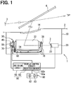
- an HUD device 1 As shown in FIG. 1 , an HUD device 1 according to a first embodiment is installed in a vehicle and displays a virtual image of a display light image 3 in the vehicle.
- the HUD device 1 has a housing 10, a projector 20, an optical unit 30, a stepping motor 40, a reduction gear mechanism 50, a resilient member 60, a temperature sensor 70, an adjustment switch 80, and a control unit 90.
- the housing 10 has a hollow shape and is installed at an instrument panel 2 in the vehicle.
- the housing 10 accommodates the constituent components 20, 30, 40, 50, 60, 70, and others of the device 1 in front of the driver's seat in the vehicle.
- the housing 10 has a translucent light emitting window 14 at a place vertically facing a windshield 4 as a projection member in front of the driver's seat in the vehicle.
- the projector 20 is mainly composed of a liquid crystal panel or an organic EL panel of a transillumination type or the like and has a screen 22.
- the screen 22 is transilluminated by a backlight incorporated in the projector 20.
- An image displayed as a real image on the screen 22 illuminates by receiving the transillumination and thus is projected as a display light image 3.
- the display light image 3 projected from the projector 20 represents vehicle-related information related to a vehicle.
- a display light image 3 according to the present embodiment represents navigation information such as a vehicle traveling direction as shown in FIG. 2 .
- a display light image 3 may also represent vehicle state information such as a vehicle speed, a remaining fuel amount, and a cooling water temperature and vehicle exterior situation information such as a traffic situation other than navigation information.
- the optical unit 30 includes a plurality of optical members including a reflecting mirror 32. Other members than the reflecting mirror 32 however are omitted in FIG. 1 .
- the reflecting mirror 32 has a reflective surface 34 concaved in a smoothly curved surface shape and is a so-called concave mirror.
- the reflecting mirror 32 expands a display light image 3 entering the reflective surface 34 directly or indirectly from the projector 20 and reflects the display light image 3 toward the side of the light emitting window 14.
- the display light image 3 reflected in this way passes through the light emitting window 14, is projected to the windshield 4, and thus focuses in front of the windshield 4 as shown in FIG. 2 .
- the vehicle-related information represented by the display light image 3 is displayed as a virtual image toward the side of the driver's seat in the vehicle.
- the reflecting mirror 32 has a rotation axis 38.
- the rotation axis 38 is supported rotatably by a base 16 fixed to the housing 10.
- a position of displaying a virtual image of a display light image 3 shifts vertically to the windshield 4 as shown in FIG. 2 .
- a position of displaying a virtual image of a display light image 3 is adjustable between a lower limit display position D1 shown by the solid line in FIG. 2 and an upper limit display position Du shown by the broken line in FIG. 2 due to the optical properties of the optical unit 30 and the windshield 4.
- the stepping motor 40 is a permanent magnet type of a claw pole structure.
- the stepping motor 40 has a magnetic casing 46, a rotor 41, and stators 44 and 45.
- the magnetic casing 46 is obtained by forming a magnetic material into a hollow shape.
- the rotor 41 is formed by assembling a rotor magnet 43 around the outer circumference of a motor shaft 42.
- the motor shaft 42 is supported rotatably by the magnetic casing 46.
- the rotor magnet 43 is formed by aligning a plurality of N and S magnetic poles alternately in a rotation direction.
- the two phase stators 44 and 45 are retained by the magnetic casing 46 on the outer circumferential side of the rotor 41.
- the stator 44 of an A phase has magnetic yokes 441 and 442 and a coil 443.
- the stator 45 of a B phase has magnetic yokes 451 and 452 and a coil 453.
- the coils 443 and 453 of the respective A and B phases receive electricity by a drive signal and are excited and thus the rotor magnet 43 rotates together with the motor shaft 42.
- a drive signal is applied in accordance with a cosine function of alternating an amplitude in response to an electric angle as shown by the thick solid line in the graph of FIG. 5 .
- a drive signal is applied in accordance with a sine function of alternating an amplitude in response to an electric angle as shown by the thin solid line in the graph of FIG. 5 .
- a rotational position of the motor shaft 42 therefore comes to be a position responding to an electric angle of a drive signal applied to the coils 443 and 453 of the respective A and B phases.
- the reduction gear mechanism 50 shares the magnetic casing 46 with the stepping motor 40.
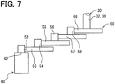
- the reduction gear mechanism 50 has a plurality of transmission gears 52, 53, 54, 55, 56, 57, 58, and 59 in the interior of the magnetic casing 46.
- the whole transmission gears 52, 53, 54, 55, 56, 57, 58, and 59 including tooth-shaped portions 52a, 53a, 54a, 55a, 56a, 57a, 58a, and 59a comprise a resin respectively.
- creep deformation caused by a residual stress during the resin forming and the like is likely to be generated as shown schematically by white allows in FIG. 6A .
- every one of the transmission gears 52, 53, 54, 55, 56, 57, 58, and 59 is defined as a "specific gear" where creep deformation is predicted.
- a first stage transmission gear 52 is formed in the motor shaft 42.
- a first idler transmission gear 53 and a first pinion transmission gear 54 are formed integrally and supported rotatably by the magnetic casing 46.
- a tooth-shaped portion 53a of the first idler transmission gear 53 links with a tooth-shaped portion 52a of the first stage transmission gear 52 by engagement.
- a second idler transmission gear 55 and a second pinion transmission gear 56 are formed integrally and supported rotatably by the magnetic casing 46.
- a tooth-shaped portion 55a of the second idler transmission gear 55 links with a tooth-shaped portion 54a of the first pinion transmission gear 54 by engagement.
- a third idler transmission gear 57 and a third pinion transmission gear 58 are formed integrally and supported rotatably by the magnetic casing 46.
- a tooth-shaped portion 57a of the third idler transmission gear 57 links with a tooth-shaped portion 56a of the second pinion transmission gear 56 by engagement.
- a final stage transmission gear 59 is formed in a rotation shaft 38.
- a tooth-shaped portion 59a of the final stage transmission gear 59 links with a tooth-shaped portion 58a of the third pinion transmission gear 58 by engagement.
- the rotation of the motor shaft 42 is decelerated and transferred to the rotation shaft 38.
- the rotation shaft 38 is driven so that a position of displaying a virtual image of a display light image 3 may shift toward an upward upper limit display position Du as shown in FIG. 2 .
- the rotation shaft 38 is driven so that a position of displaying a virtual image of a display light image 3 may shift toward a downward lower limit display position D1 as shown in FIG. 2 .
- the resilient member 60 is a so-called tension coil spring comprising a metal.
- An end of the resilient member 60 is locked by the reflecting mirror 32.
- the other end of the resilient member 60 is locked by the base 16.
- the resilient member 60 generates a restoring force so as to energize the rotation shaft 38 toward one side in a rotation direction.
- the restoring force comes to be a force generated in the direction of eliminating a backlash by engaging the tooth-shaped portions 52a, 53a, 54a, 55a, 56a, 57a, 58a, and 59a with each other, those tooth-shaped portions constituting places where the transmission gears 52, 53, 54, 55, 56, 57, 58, and 59 link respectively.
- Creep deformation causing such a deviation of a virtual image display position is generated more for a shorter period of time particularly as an environmental temperature T (refer to FIG. 8A ) of the transmission gears 52, 53, 54, 55, 56, 57, 58, and 59 rises.
- the deviation of a virtual image display position therefore is also generated more for a shorter period of time as an environmental temperature T rises.
- an environmental temperature T at which a large creep deformation is predicted is defined as a predicted deformation temperature Te (refer to FIG. 8A ).
- a predicted deformation temperature Te is set at an environmental temperature T, for example a predetermined value such as 85°C, at which a deviation that gives a sense of incongruity to an occupant in a vehicle is predicted to be generated as a deviation of a virtual image display position caused by creep deformation of the transmission gears 52, 53, 54, 55, 56, 57, 58, and 59.
- a deviation of a virtual image display position predicted to be generated by creep deformation at such a predicted deformation temperature Te is defined as a predicted display deviation ⁇ De as shown in FIG. 8A .
- Such a predicted deformation temperature Te and a predicted display deviation ⁇ De may be measured actually from a result of experiment using a plurality of sets of transmission gears 52, 53, 54, 55, 56, 57, 58, and 59 or may be estimated by simulation.
- the temperature sensor 70 is accommodated in the interior of the magnetic casing 46 together with the transmission gears 52, 53, 54, 55, 56, 57, 58, and 59.
- the temperature sensor 70 therefore is installed at the instrument panel 2 in a vehicle.
- the temperature sensor 70 is mainly composed of a thermistor that changes an electric resistance relatively largely in response to the change of a temperature.
- the temperature sensor 70 detects an environmental temperature T common to the transmission gears 52, 53, 54, 55, 56, 57, 58, and 59 in the interior of the magnetic casing 46.
- the temperature sensor 70 outputs a temperature signal representing a detected environmental temperature T.
- the adjustment switch 80 is installed around a driver's seat in a vehicle so as to be operable by an occupant.
- the adjustment switch 80 has operation members 82 and 83 of a lever type, a push type, or the like.
- An up operation member 82 is operated by an occupant who wants to shift a position of displaying a virtual image of a display light image 3 upward.
- the adjustment switch 80 outputs a command signal to give an up adjustment command.
- a down operation member 83 is operated by an occupant who wants to shift a position of displaying a virtual image of a display light image 3 downward.
- the adjustment switch 80 outputs a command signal to give a down adjustment command.
- the control unit 90 is installed in the exterior or the interior of the housing 10.
- the control unit 90 is formed by combining a display control circuit 92 and a switching circuit 93.
- the display control circuit 92 is mainly composed of a microcomputer having a processor 92a and a memory 92b.
- the display control unit 92 is connected electrically to the projector 20, the temperature sensor 70, and the adjustment switch 80.
- the switching circuit 93 has a plurality of transistors as switching elements 94. Collectors of the switching elements 94 are connected electrically to either of the coils 443 and 453. Emitters and bases of the switching elements 94 are connected electrically to an earth terminal of a vehicle and the display control circuit 92 respectively.
- the switching elements 94 change stepwise a drive signal applied to the coils 443 and 453 of the respective A and B phases in accordance with a base signal inputted from the display control circuit 92. As a result, the rotational position of the motor shaft 42 shifts in response to an electric angle of the drive signal applied to the coils 443 and 453 of the respective A and B phases. Then the control of a base signal sent to the switching elements 94 is explained hereunder as the control of a rotational position of the motor shaft 42.
- the display control circuit 92 controls the display of an image projected by the projector 20. Along with this, the display control circuit 92 controls a rotational position of the motor shaft 42 in accordance with a temperature signal inputted from the temperature sensor 70 and a command signal inputted from the adjustment switch 80.
- the display control circuit 92 shifts a rotational position of the motor shaft 42 toward the forward rotation side in accordance with an up adjustment command by the operation of the up operation member 82. As a result, a position of displaying a virtual image of a display light image 3 shifts upward in accordance with the up adjustment command.
- the display control circuit 92 shifts a rotational position of the motor shaft 42 toward the backward rotation side in accordance with a down adjustment command by the operation of the down operation member 83. As a result, a position of displaying a virtual image of a display light image 3 shifts downward in accordance with the down adjustment command.
- an up adjustment command and a down adjustment command are referred collectively to as an adjustment command.
- the display control circuit 92 controls a rotational position of the motor shaft 42 in response to an environmental temperature T detected by the temperature sensor 70. Then rotational position control responding to an environmental temperature T is hereunder explained in detail.
- the display control circuit 92 executes a control program stored in the memory 92b in order to carry out rotational position control responding to an environmental temperature T by the processor 92a; and thus builds a plurality of blocks 921 and 922 shown in FIG. 9 functionally.
- the correction execution block 921 corrects a rotational position of the motor shaft 42 by a predetermined correction amount ⁇ C (refer to FIG. 8B ).
- the correction execution block 921 according to the present embodiment corrects a rotational position by a correction amount ⁇ C when an environmental temperature T detected by the temperature sensor 70 rises to a temperature of a predicted deformation temperature Te or more for the first time after the HUD device 1 is installed in a vehicle.
- a correction amount ⁇ C is set on the backward rotation side of the motor shaft 42 so as to reduce a predicted display deviation ⁇ De at a temperature of a predicted deformation temperature Te or more by shifting a position of displaying a virtual image of a display light image 3 downward as schematically shown by a dot-hatched arrow in FIG. 8B .
- a correction amount ⁇ C is set at a variation of rotating the motor shaft 42 backward in order to return a predicted display deviation ⁇ De to the state before deviation, for example a predetermined value of 360 degrees corresponding to two steps, as an electric angle variation of a drive signal applied to the coils 443 and 453 of the respective A and B phases.
- Such a correction amount ⁇ C is set beforehand at a value of shifting a rotational position of the motor shaft 42 toward the backward rotation side so as to return a predicted display deviation ⁇ De actually measured or estimated as stated earlier to the state before deviation and stored in the memory 92b. Then the correction execution block 921 reads out the correction amount ⁇ C stored in the memory 92b and thus corrects the rotational position by the correction amount ⁇ C. As a result, an electric angle of a drive signal applied to the coils 443 and 453 of the respective A and B phases shifts to the extent corresponding to the correction amount ⁇ C. The rotational position of the motor shaft 42 is therefore corrected toward the backward rotation side of returning the predicted display deviation ⁇ De to the state before deviation.
- the post-correction control block 922 controls the rotational position of the motor shaft 42 from a current position corrected by a correction amount ⁇ C to a position following the first adjustment command. Further, when a second or subsequent adjustment command is given after the rotational position is corrected, the post-correction control block 922 controls the rotational position of the motor shaft 42 from a current position controlled through the position corrected by the correction amount ⁇ C to a position following the second or subsequent adjustment command.
- the display control circuit 92 executes a display control flow shown in FIG. 10 and then the details are explained hereunder.
- the display control flow starts in response to on operation of a power switch of a vehicle and finishes in response to off operation of the switch. Further, during the display control flow, a virtual image of a display light image 3 continues to be displayed by projecting the display light image 3 from the projector 20.
- "S" in the display control flow means a step.
- a temperature signal representing an environmental temperature T detected by the temperature sensor 70 is obtained. Successively, at S103, whether or not the environmental temperature T detected by the temperature sensor 70 is the predicted deformation temperature Te or more is determined on the basis of the temperature signal obtained at immediately preceding S102. When positive determination is given as a result, the process shifts to S104.
- a rotational position of the motor shaft 42 is corrected by a correction amount ⁇ C stored in the memory 92b.
- a temperature rise flag representing that an environmental temperature T has risen to a temperature of a predicted deformation temperature Te or more for the first time after the device is installed in a vehicle is stored in the memory 92b.
- the temperature rise flag is not deleted regardless of on or off operation of a power switch as long as the initialization of the memory 92b is not forced from an exterior.
- the process shifts to S106. Further, also when negative determination is given at S103, the process shifts to S106. Furthermore, even when positive determination is given at S101, the process shifts to S106.
- the process shifts from any of S101, S103, and S105, at S106, whether or not an adjustment command is given by an occupant is determined on the basis of the existence or non-existence of a command signal from the adjustment switch 80.
- negative determination is given as a result, the process returns to S101.
- positive determination is given, the process shifts to S107.
- a rotational position of the motor shaft 42 is controlled to a position conforming to an adjustment command and then the process returns to S101.
- a rotational position of the motor shaft 42 is controlled from a current position corrected at S105.
- a rotational position of the motor shaft 42 is controlled from a current position controlled through a position corrected at S104.
- the transmission gears 52, 53, 54, 55, 56, 57, 58, and 59 where creep deformation is predicted are defined as "specific gears" and correction triggered by an environmental temperature T of the gears is given to a rotational position of the stepping motor 40.
- a rotational position of the stepping motor 40 is corrected toward the side of returning a predicted display deviation ⁇ De related to a position of displaying a virtual image of a display light image 3 to the state before deviation.
- the predicted display deviation ⁇ De is a deviation estimated to be generated at a position of displaying a virtual image of a display light image 3 by creep deformation at a predicted deformation temperature Te. Even when the transmission gears 52, 53, 54, 55, 56, 57, 58, and 59 incur creep deformation at an environmental temperature T of a predicted deformation temperature Te or more therefore, by correcting a rotational position toward the side of returning the predicted display deviation ⁇ De to the state before deviation, a position of displaying a virtual image of a display light image 3 can be inhibited from deviating in a vehicle.
- a rotational position of the stepping motor 40 shifts toward the side of returning a predicted display deviation ⁇ De to the state before deviation by correcting the rotational position by a correction amount ⁇ C. After the shift therefore, the rotational position of the stepping motor 40 is controlled in accordance with an adjustment command on the basis of the corrected position.
- a position of displaying a virtual image of a display light image 3 can be controlled while the state of reducing deviation caused by the creep deformation of the transmission gears 52, 53, 54, 55, 56, 57, 58, and 59 is maintained.
- an environmental temperature T of the transmission gears 52, 53, 54, 55, 56, 57, 58, and 59 is likely to rise to a temperature of a predicted deformation temperature Te or more by the travel of a vehicle in which the HUD device 1 is installed.
- a rotational position is corrected.
- the situation that creep deformation may be generated in the transmission gears 52, 53, 54, 55, 56, 57, 58, and 59 can be captured without fail and the rotational position can be corrected timely. Consequently, the reliability of the effect of inhibiting a position of displaying a virtual image of a display light image 3 from deviating can be ensured.
- the temperature sensor 70 is accommodated in the interior of the magnetic casing 46 of the reduction gear mechanism 50 together with the transmission gears 52, 53, 54, 55, 56, 57, 58, and 59.
- the temperature sensor 70 can detect an environmental temperature T of the transmission gears 52, 53, 54, 55, 56, 57, 58, and 59 as close as possible with a high degree of accuracy. Consequently, the rise of an environmental temperature T to a temperature of a predicted deformation temperature Te or more can be captured accurately and a rotational position can be corrected timely.
- creep deformation is likely to be generated at a temperature of a predicted deformation temperature Te or more.
- a second embodiment is a modification of the first embodiment.
- S2100 is added to a display control flow as shown in FIG. 11 .
- a process shifts to S2100 when negative determination is given at S101.
- S2100 whether or not a set time has elapsed since a vehicle stopped is determined.
- a set time is set at a time required for raising an environmental temperature T detected by the temperature sensor 70 to the utmost and saturating the environmental temperature T in a vehicle because the vehicle stops and thus an air conditioner and the like stop.
- negative determination is given at S2100
- the process shifts to S106.
- positive determination is given at S2100, the process shifts to S102.
- a rotational position is corrected.
- the situation that creep deformation may be generated in the transmission gears 52, 53, 54, 55, 56, 57, 58, and 59 can be captured without fail and the rotational position can be corrected timely. Consequently, the reliability of the effect of inhibiting a position of displaying a virtual image of a display light image 3 from deviating can be ensured.
- a third embodiment is a modification of the second embodiment.
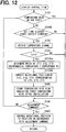
- S3104a and S3104b are executed in place of S104 in a display control flow as shown in FIG. 12 .
- a process shifts to S3104a when positive determination is given at S103.
- S3104a which of a plurality of temperature ranges of ⁇ T1, ⁇ T2, and ⁇ T3 of a predicted deformation temperature Te or more an environmental temperature T detected by the temperature sensor 70 corresponds to is determined on the basis of a temperature signal obtained at the closest S102.
- three temperature ranges ⁇ T1, ⁇ T2, and ⁇ T3 are set.
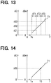
- the temperature ranges ⁇ T1, ⁇ T2, and ⁇ T3 are set with temperatures that are predicted to cause notable differences in a predicted display deviation ⁇ De felt by an occupant defined as boundaries on the basis of a temperature correlation lt between an environmental temperature T of a predicted deformation temperature Te or more and a predicted display deviation ⁇ De as shown in FIG. 13 .
- the temperature ranges ⁇ T1, ⁇ T2, and ⁇ T3 are set on the basis of a temperature correlation lt of increasing a predicted display deviation ⁇ De in proportion to the rise of an environmental temperature T.
- a rotational position of the motor shaft 42 is corrected by any one of a plurality of values ⁇ C1, ⁇ C2, and ⁇ C3 that are variable correction amounts ⁇ C stored in the memory 92b as a function of the correction execution block 921.
- three correction amounts ⁇ C1, ⁇ C2, and ⁇ C3 are set in response to the three temperature ranges ⁇ T1, ⁇ T2, and ⁇ T3.
- the correction amounts ⁇ C1, ⁇ C2, and ⁇ C3 are set at different values corresponding to the temperature ranges ⁇ T1, ⁇ T2, and ⁇ T3 respectively on the basis of a temperature correlation lt between an environmental temperature T of a predicted deformation temperature Te or more and a predicted display deviation ⁇ De as shown in FIG. 13 .
- the correction amounts ⁇ C1, ⁇ C2, and ⁇ C3 are set so as to increase the values in proportion to the rise of the relevant temperature ranges ⁇ T1, ⁇ T2, and ⁇ T3.
- a value corresponding to any one of the temperature ranges ⁇ T1, ⁇ T2, and ⁇ T3 determined at immediately preceding S3104a is selected from the correction amounts ⁇ C1, ⁇ C2, and ⁇ C3 and a rotational position is corrected by the selected value.
- the process shifts to S105.
- a rotational position is corrected by variable correction amounts ⁇ C1, ⁇ C2, and ⁇ C3 based on a temperature correlation lt between an environmental temperature T of a predicted deformation temperature Te or more and a predicted display deviation ⁇ De.
- appropriate correction amounts ⁇ C1, ⁇ C2, and ⁇ C3 are selected in consideration of even the general knowledge that a predicted display deviation ⁇ De varies in response to an environmental temperature T; and can be used for rotational position correction. Consequently, the reliability of the effect of inhibiting a position of displaying a virtual image of a display light image 3 from deviating can be ensured.
- a rotational position is corrected by a value corresponding to a relevant range of an environmental temperature T in the correction amounts ⁇ C1, ⁇ C2, and ⁇ C3 which are set at different values in accordance with the multiple temperature ranges ⁇ T1, ⁇ T2, and ⁇ T3 of a predicted deformation temperature Te or more on the basis of a temperature correlation lt.
- correction amounts ⁇ C1, ⁇ C2, and ⁇ C3 appropriate to temperature ranges ⁇ T1, ⁇ T2, and ⁇ T3 that are predicted to cause notable differences in a predicted display deviation ⁇ De felt by an occupant are selected respectively and can be used for rotational position correction. Consequently, a high degree of reliability in the effect of inhibiting a position of displaying a virtual image of a display light image 3 from deviating can be ensured.
- a rotational position may be corrected by the correction execution block 921 when an environmental temperature T detected by the temperature sensor 70 comes to be a temperature of a predicted deformation temperature Te or more for the first time after production or after factory shipment before the HUD device 1 is installed in a vehicle.
- an environmental temperature T detected by the temperature sensor 70 comes to be a temperature of a predicted deformation temperature Te or more for the first time after production or after factory shipment before the HUD device 1 is installed in a vehicle.
- at least a part of the multiple blocks 921 and 922 may be configured as hardware by at least one IC or the like.
- a zero position serving as a reference for controlling a rotational position of the motor shaft 42 may be set.
- control may be executed so as to follow an adjustment command with the corrected zero position used as a reference.
- gears excluding at least one of the transmission gears 52, 53, 54, 55, 56, 57, 58, and 59 may comprise a material that does not generate creep deformation easily even when an environmental temperature T comes to be a temperature of a predicted deformation temperature Te or more.
- at least one transmission gear comprising a resin similarly to the above embodiments is defined as a "specific gear”.
- only the tooth-shaped portions 52a, 53a, 54a, 55a, 56a, 57a, 58a, and 59a or parts including the tooth-shaped portions 52a, 53a, 54a, 55a, 56a, 57a, 58a, and 59a may comprise a resin.
- At least one gear defined as a "specific gear" in the transmission gears 52, 53, 54, 55, 56, 57, 58, and 59 may comprise a material other than a resin as long as creep deformation causing a virtual image display position to be deviated to the extent of giving a sense of incongruity to an occupant is generated.
- a torsion spring of various kinds such as a torsion coil spring or a spiral spring, may be adopted as the resilient member 60.
- any one of the shafts of the transmission gears 53, 54, 55, 56, 57, and 58 or the motor shaft 42 may be energized by the resilient member 60.
- the resilient member 60 similarly to the above embodiments, the resilient member 60 generates a restoring force in a direction of engaging the tooth-shaped portions 52a, 53a, 54a, 55a, 56a, 57a, 58a, and 59a constituting the respective link places of the transmission gears 52, 53, 54, 55, 56, 57, 58, and 59 with each other.
- a thermometer of various kinds, of a thermocouple type or an infrared type may be adopted as the temperature sensor 70.
- the temperature sensor 70 may be installed outside the magnetic casing 46 in the interior of the housing 10.
- the temperature sensor 70 may be installed outside the housing 10.
- an environmental temperature T may be detected by a temperature sensor installed at a place different from the HUD device 1 in a vehicle, such as a room temperature sensor of an air conditioner, in place of the temperature sensor 70 exclusively used in the HUD device 1 like the above embodiments.
- a laser scanner of projecting a laser light forming a display light image 3 by an electromechanical system, a video display system of projecting a visible light or a laser light forming a display light image 3 by a digital mirror device, or the like may be adopted as the projector 20.
- a display light image 3 may be projected toward a combiner or the like installed exclusively for the HUD device 1 in a vehicle.
- a display control flow may be changed so as to correct a rotational position when an environmental temperature T in a vehicle rises to a temperature of a predicted deformation temperature Te or more during the travel of the vehicle.
- whether or not a vehicle is in a traveling state is determined at S2100 and, when positive determination is given, the process shifts to S102.
- the number of sets of temperature ranges and correction amounts may be set at two or four or more in place of three described above.
- the process may shift to S102.
- a value 8C0 that is a correction amount ⁇ C corresponding to a value T0 as an environmental temperature T one to one on the basis of a temperature correlation lt of increasing a predicted display deviation ⁇ De in proportion to the rise of an environmental temperature T may be used for correcting a rotational position.
- a rotational position is corrected at S3104b by a correction amount ⁇ C0 corresponding to an environmental temperature T0 based on a signal obtained at S102.
Landscapes
- Engineering & Computer Science (AREA)
- Physics & Mathematics (AREA)
- Chemical & Material Sciences (AREA)
- Combustion & Propulsion (AREA)
- Transportation (AREA)
- Mechanical Engineering (AREA)
- General Physics & Mathematics (AREA)
- Optics & Photonics (AREA)
- Instrument Panels (AREA)
Abstract
Description
- This application is based on Japanese Patent Application No.
2015-188752 filed on September 25, 2015 2016-33523 filed on February 24, 2016 - The present disclosure relates to a head-up display (hereunder referred to as HUD) device installed in a vehicle.
- An HUD device to display a virtual image of a display light image representing vehicle-related information related to a vehicle by projecting the display light image with a projector and reflecting the display light image with a reflecting mirror has heretofore been known widely. By using a reflecting mirror in this way, a space occupied by an HUD device in a vehicle can be reduced substantially.
- As such an HUD device, a device that adjusts a position of displaying a virtual image of a display light image by decelerating the rotation of a stepping motor with a reduction gear mechanism, transferring the rotation to a reflecting mirror, and thus driving the reflecting mirror is disclosed in
Patent Document 1. In the device disclosed inPatent Document 1, a rotational position of a stepping motor is controlled in accordance with an adjustment instruction from an occupant of a vehicle and resultantly a position of displaying a virtual image of a display light image can be adjusted appropriately to a position expected by the occupant. In addition, in the device disclosed inPatent Document 1, in a reduction gear mechanism, a resilient member generates a restoring force in the direction of engaging transmission gears with each other and resultantly a backlash between the transmission gears disappears. As a result, a deviation caused by a backlash between transmission gears is not easily generated at a position of displaying a virtual image of a display light image. - Patent Document 1:
JP 2011-131651 A - With a device disclosed in
Patent Document 1 however, the environmental temperature of transmission gears rises in a vehicle. As a result, the transmission gears incur creep deformation in the manner of increasing a backlash at a place where the transmission gears link with each other by engagement. On this occasion, the transmission gears receiving a restoring force of a resilient member rotate so as to reduce the backlash. A position of displaying a virtual image of a display light image therefore deviates undesirably and hence it has been concerned that an occupant may feel a sense of incongruity. - The present disclosure addresses the issues described above. Thus, it is an objective of the present disclosure to provide an HUD device inhibiting a position of displaying a virtual image of a display light image from deviating in a vehicle.
- To achieve the objective, a head-up display device installed in a vehicle in a first aspect of the present disclosure includes a projector that projects a display light image representing vehicle-related information related to the vehicle, an optical unit that includes a drivable reflecting mirror, which reflects the display light image projected by the projector, and that adjusts a virtual image display position where a virtual image of the display light image reflected by the reflecting mirror is displayed by drive of the reflecting mirror, a stepping motor that rotates to drive the reflecting mirror, a reduction gear mechanism that rotatably includes a plurality of transmission gears, which decelerate the rotation of the stepping motor and transmit the rotation to the reflecting mirror, a resilient member that generates a restoring force in a direction that the plurality of transmission gears are engaged with each other, and a control unit that controls a rotational position of the stepping motor in accordance with an adjustment command by an occupant of the vehicle. At least one of the plurality of transmission gears that is predicted to incur a creep deformation is defined as a specific gear. An environmental temperature of the specific gear, at which the specific gear is predicted to incur the creep deformation, is defined as a predicted deformation temperature. A deviation predicted to be caused at the virtual image display position by the creep deformation at the predicted deformation temperature is defined as a predicted display deviation. The control unit corrects the rotational position in a direction to reduce the predicted display deviation when the environmental temperature rises to the predicted deformation temperature or higher.
- In this first aspect, at least one transmission gear where creep deformation is predicted is defined as a specific gear in a reduction gear mechanism and correction triggered by the environmental temperature of the specific gear is given to the rotational position of a stepping motor. Concretely, when an environmental temperature rises to a temperature of a predicted deformation temperature or more at which creep deformation is predicted, the rotational position of a stepping motor is corrected toward the side of reducing a predicted display deviation related to a position of displaying a virtual image of a display light image. Here, a predicted display deviation is a deviation predicted to be generated at a position of displaying a virtual image of a display light image by creep deformation at a temperature of a predicted deformation temperature or more. Even when a specific gear incurs creep deformation at a high environmental temperature of a predicted deformation temperature or more therefore, a position of displaying a virtual image of a display light image can be inhibited from deviating in a vehicle by correcting a rotational position toward the side of reducing a predicted display deviation.
- The control unit in a second aspect of the present disclosure includes a correction execution block that executes the correction of the rotational position by a correction amount, which shifts the rotational position in the direction to reduce the predicted display deviation, when the environmental temperature rises to the predicted deformation temperature or higher, and a post-correction control block that controls the rotational position in accordance with the adjustment command, with the rotational position corrected by the correction execution block used as a reference.
- In this second aspect, when an environmental temperature rises to a temperature of a predicted deformation temperature or more, a rotational position of a stepping motor shifts toward the side of reducing a predicted display deviation by correcting the rotational position by a correction amount. Then after the shift, the rotational position of the stepping motor is controlled in accordance with an adjustment command with a corrected position used as a reference. As a result, once a rotational position is corrected by an environmental temperature of a predicted deformation temperature or more, a position of displaying a virtual image of a display light image can be controlled in the state of reducing a deviation caused by the creep deformation of a specific gear.
- The above and other objects, features and advantages of the present disclosure will become more apparent from the following detailed description made with reference to the accompanying drawings. In the drawings:
-
FIG. 1 is a schematic configuration diagram showing an HUD device according to a first embodiment; -
FIG. 2 is a schematic view showing a state of displaying a virtual image of a display light image by the HUD device inFIG. 1 ; -
FIG. 3 is a sectional view showing the stepping motor and the reduction gear mechanism inFIG. 1 ; -
FIG. 4 is an electric circuit diagram showing a state of electrically connecting the stepping motor to the control unit inFIG. 1 ; -
FIG. 5 is a characteristic diagram for explaining a drive signal applied to the stepping motor inFIG. 1 ; -
FIG. 6A is a schematic view for explaining creep deformation generated in the transmission gears inFIG. 1 andFIG. 6B is a schematic view for explaining creep deformation generated in the transmission gears inFIG. 1 ; -
FIG. 7 is a schematic view showing a link relationship between the stepping motor and the reduction gear mechanism inFIG. 1 ; -
FIG. 8A is a schematic view for explaining a deviation generated at the virtual image display position shown inFIG. 2 andFIG 8B is a schematic view for explaining correction for returning the deviation; -
FIG. 9 is a block diagram showing a plurality of blocks constituting the display control circuit inFIG. 1 ; -
FIG. 10 is a flowchart showing a display control flow in the display control circuit inFIG. 1 ; -
FIG. 11 is a flowchart showing a display control flow in a display control circuit according to a second embodiment; -
FIG. 12 is a flowchart showing a display control flow in a display control circuit according to a third embodiment; -
FIG. 13 is a characteristic diagram for explaining correction by a display control circuit according to the third embodiment; and -
FIG. 14 is a characteristic diagram for explaining correction by a display control circuit according to a modification. - A plurality of embodiments according to the present disclosure are explained hereunder in reference to the drawings. Here, constituent components corresponding to each other in the embodiments are represented by an identical reference sign and thus a duplicate explanation is avoided sometimes. When only a part of a configuration is explained in an embodiment, a configuration of another embodiment explained previously can be applied to the other part of the relevant embodiment. Further, not only configurations specified in the explanation of an embodiment can be combined but also configurations of a plurality of embodiments can be combined partially with each other even when they are not specified as long as there is no problem with the combination.
- As shown in
FIG. 1 , anHUD device 1 according to a first embodiment is installed in a vehicle and displays a virtual image of adisplay light image 3 in the vehicle. TheHUD device 1 has ahousing 10, aprojector 20, anoptical unit 30, astepping motor 40, areduction gear mechanism 50, aresilient member 60, atemperature sensor 70, anadjustment switch 80, and acontrol unit 90. - The
housing 10 has a hollow shape and is installed at aninstrument panel 2 in the vehicle. Thehousing 10 accommodates theconstituent components device 1 in front of the driver's seat in the vehicle. Thehousing 10 has a translucentlight emitting window 14 at a place vertically facing awindshield 4 as a projection member in front of the driver's seat in the vehicle. - The
projector 20 is mainly composed of a liquid crystal panel or an organic EL panel of a transillumination type or the like and has ascreen 22. Thescreen 22 is transilluminated by a backlight incorporated in theprojector 20. An image displayed as a real image on thescreen 22 illuminates by receiving the transillumination and thus is projected as a displaylight image 3. The displaylight image 3 projected from theprojector 20 represents vehicle-related information related to a vehicle. A displaylight image 3 according to the present embodiment represents navigation information such as a vehicle traveling direction as shown inFIG. 2 . Here, a displaylight image 3 may also represent vehicle state information such as a vehicle speed, a remaining fuel amount, and a cooling water temperature and vehicle exterior situation information such as a traffic situation other than navigation information. - As shown in
FIG. 1 , theoptical unit 30 includes a plurality of optical members including a reflectingmirror 32. Other members than the reflectingmirror 32 however are omitted inFIG. 1 . The reflectingmirror 32 has areflective surface 34 concaved in a smoothly curved surface shape and is a so-called concave mirror. The reflectingmirror 32 expands a displaylight image 3 entering thereflective surface 34 directly or indirectly from theprojector 20 and reflects the displaylight image 3 toward the side of thelight emitting window 14. The displaylight image 3 reflected in this way passes through thelight emitting window 14, is projected to thewindshield 4, and thus focuses in front of thewindshield 4 as shown inFIG. 2 . As a result, the vehicle-related information represented by the displaylight image 3 is displayed as a virtual image toward the side of the driver's seat in the vehicle. - As shown in
FIG. 1 , the reflectingmirror 32 has arotation axis 38. Therotation axis 38 is supported rotatably by a base 16 fixed to thehousing 10. By rotationally driving therotation axis 38, a position of displaying a virtual image of a displaylight image 3 shifts vertically to thewindshield 4 as shown inFIG. 2 . In the present embodiment here, a position of displaying a virtual image of a displaylight image 3 is adjustable between a lower limit display position D1 shown by the solid line inFIG. 2 and an upper limit display position Du shown by the broken line inFIG. 2 due to the optical properties of theoptical unit 30 and thewindshield 4. - As shown in
FIG. 3 , the steppingmotor 40 is a permanent magnet type of a claw pole structure. The steppingmotor 40 has amagnetic casing 46, arotor 41, andstators magnetic casing 46 is obtained by forming a magnetic material into a hollow shape. Therotor 41 is formed by assembling arotor magnet 43 around the outer circumference of amotor shaft 42. Themotor shaft 42 is supported rotatably by themagnetic casing 46. Therotor magnet 43 is formed by aligning a plurality of N and S magnetic poles alternately in a rotation direction. The twophase stators magnetic casing 46 on the outer circumferential side of therotor 41. As shownFIGS. 3 and4 , thestator 44 of an A phase hasmagnetic yokes coil 443. Likewise, thestator 45 of a B phase hasmagnetic yokes coil 453. - By this configuration, in the stepping
motor 40, thecoils rotor magnet 43 rotates together with themotor shaft 42. Here, to thecoil 443 of the A phase, a drive signal is applied in accordance with a cosine function of alternating an amplitude in response to an electric angle as shown by the thick solid line in the graph ofFIG. 5 . Likewise, to thecoil 453 of the B phase, a drive signal is applied in accordance with a sine function of alternating an amplitude in response to an electric angle as shown by the thin solid line in the graph ofFIG. 5 . A rotational position of themotor shaft 42 therefore comes to be a position responding to an electric angle of a drive signal applied to thecoils - As shown in
FIG. 3 , thereduction gear mechanism 50 shares themagnetic casing 46 with the steppingmotor 40. Along with that, thereduction gear mechanism 50 has a plurality of transmission gears 52, 53, 54, 55, 56, 57, 58, and 59 in the interior of themagnetic casing 46. The whole transmission gears 52, 53, 54, 55, 56, 57, 58, and 59 including tooth-shapedportions FIG. 6A . In the present embodiment therefore, every one of the transmission gears 52, 53, 54, 55, 56, 57, 58, and 59 is defined as a "specific gear" where creep deformation is predicted. - As shown in
FIGS. 3 and7 , a firststage transmission gear 52 is formed in themotor shaft 42. A firstidler transmission gear 53 and a firstpinion transmission gear 54 are formed integrally and supported rotatably by themagnetic casing 46. A tooth-shapedportion 53a of the firstidler transmission gear 53 links with a tooth-shapedportion 52a of the firststage transmission gear 52 by engagement. A secondidler transmission gear 55 and a secondpinion transmission gear 56 are formed integrally and supported rotatably by themagnetic casing 46. A tooth-shapedportion 55a of the secondidler transmission gear 55 links with a tooth-shapedportion 54a of the firstpinion transmission gear 54 by engagement. A thirdidler transmission gear 57 and a thirdpinion transmission gear 58 are formed integrally and supported rotatably by themagnetic casing 46. A tooth-shapedportion 57a of the thirdidler transmission gear 57 links with a tooth-shapedportion 56a of the secondpinion transmission gear 56 by engagement. A finalstage transmission gear 59 is formed in arotation shaft 38. A tooth-shapedportion 59a of the finalstage transmission gear 59 links with a tooth-shapedportion 58a of the thirdpinion transmission gear 58 by engagement. - By this configuration, in the
reduction gear mechanism 50, the rotation of themotor shaft 42 is decelerated and transferred to therotation shaft 38. As a result, when themotor shaft 42 rotates forward, therotation shaft 38 is driven so that a position of displaying a virtual image of a displaylight image 3 may shift toward an upward upper limit display position Du as shown inFIG. 2 . On the other hand, when themotor shaft 42 rotates backward, therotation shaft 38 is driven so that a position of displaying a virtual image of a displaylight image 3 may shift toward a downward lower limit display position D1 as shown inFIG. 2 . - As shown in
FIG. 1 , theresilient member 60 is a so-called tension coil spring comprising a metal. An end of theresilient member 60 is locked by the reflectingmirror 32. The other end of theresilient member 60 is locked by thebase 16. By such a locked form, theresilient member 60 generates a restoring force so as to energize therotation shaft 38 toward one side in a rotation direction. The restoring force comes to be a force generated in the direction of eliminating a backlash by engaging the tooth-shapedportions - Here, such creep deformation as shown in
FIG. 6A occurs in the manner of bending the teeth of the tooth-shapedportions resilient member 60 at the respective link places; thus rotate as shown schematically by the dot-hatched arrow inFIG. 6B ; and reduce a backlash to the extent of having increased by the bends of the teeth. As a result, a position of displaying a virtual image of a displaylight image 3 deviates upward as shown schematically by the white arrow inFIG. 8A . Creep deformation causing such a deviation of a virtual image display position is generated more for a shorter period of time particularly as an environmental temperature T (refer toFIG. 8A ) of the transmission gears 52, 53, 54, 55, 56, 57, 58, and 59 rises. The deviation of a virtual image display position therefore is also generated more for a shorter period of time as an environmental temperature T rises. - In the present embodiment therefore, an environmental temperature T at which a large creep deformation is predicted is defined as a predicted deformation temperature Te (refer to
FIG. 8A ). Concretely, a predicted deformation temperature Te is set at an environmental temperature T, for example a predetermined value such as 85°C, at which a deviation that gives a sense of incongruity to an occupant in a vehicle is predicted to be generated as a deviation of a virtual image display position caused by creep deformation of the transmission gears 52, 53, 54, 55, 56, 57, 58, and 59. Further, a deviation of a virtual image display position predicted to be generated by creep deformation at such a predicted deformation temperature Te is defined as a predicted display deviation δDe as shown inFIG. 8A . Such a predicted deformation temperature Te and a predicted display deviation δDe may be measured actually from a result of experiment using a plurality of sets of transmission gears 52, 53, 54, 55, 56, 57, 58, and 59 or may be estimated by simulation. - As shown in
FIGS. 1 and3 , thetemperature sensor 70 is accommodated in the interior of themagnetic casing 46 together with the transmission gears 52, 53, 54, 55, 56, 57, 58, and 59. Thetemperature sensor 70 therefore is installed at theinstrument panel 2 in a vehicle. Thetemperature sensor 70 is mainly composed of a thermistor that changes an electric resistance relatively largely in response to the change of a temperature. Thetemperature sensor 70 detects an environmental temperature T common to the transmission gears 52, 53, 54, 55, 56, 57, 58, and 59 in the interior of themagnetic casing 46. Thetemperature sensor 70 outputs a temperature signal representing a detected environmental temperature T. - As shown in
FIGS. 1 and4 , theadjustment switch 80 is installed around a driver's seat in a vehicle so as to be operable by an occupant. Theadjustment switch 80 hasoperation members operation member 82 is operated by an occupant who wants to shift a position of displaying a virtual image of a displaylight image 3 upward. By receiving the operation, theadjustment switch 80 outputs a command signal to give an up adjustment command. In contrast, adown operation member 83 is operated by an occupant who wants to shift a position of displaying a virtual image of a displaylight image 3 downward. By receiving the operation, theadjustment switch 80 outputs a command signal to give a down adjustment command. - The
control unit 90 is installed in the exterior or the interior of thehousing 10. Thecontrol unit 90 is formed by combining adisplay control circuit 92 and aswitching circuit 93. Thedisplay control circuit 92 is mainly composed of a microcomputer having aprocessor 92a and amemory 92b. Thedisplay control unit 92 is connected electrically to theprojector 20, thetemperature sensor 70, and theadjustment switch 80. As shown inFIG. 4 , the switchingcircuit 93 has a plurality of transistors as switchingelements 94. Collectors of the switchingelements 94 are connected electrically to either of thecoils elements 94 are connected electrically to an earth terminal of a vehicle and thedisplay control circuit 92 respectively. The switchingelements 94 change stepwise a drive signal applied to thecoils display control circuit 92. As a result, the rotational position of themotor shaft 42 shifts in response to an electric angle of the drive signal applied to thecoils switching elements 94 is explained hereunder as the control of a rotational position of themotor shaft 42. - In the
control unit 90 of such a configuration, thedisplay control circuit 92 controls the display of an image projected by theprojector 20. Along with this, thedisplay control circuit 92 controls a rotational position of themotor shaft 42 in accordance with a temperature signal inputted from thetemperature sensor 70 and a command signal inputted from theadjustment switch 80. - Concretely, the
display control circuit 92 shifts a rotational position of themotor shaft 42 toward the forward rotation side in accordance with an up adjustment command by the operation of theup operation member 82. As a result, a position of displaying a virtual image of a displaylight image 3 shifts upward in accordance with the up adjustment command. On the other hand, thedisplay control circuit 92 shifts a rotational position of themotor shaft 42 toward the backward rotation side in accordance with a down adjustment command by the operation of thedown operation member 83. As a result, a position of displaying a virtual image of a displaylight image 3 shifts downward in accordance with the down adjustment command. Here, in the following explanations, an up adjustment command and a down adjustment command are referred collectively to as an adjustment command. - Further, the
display control circuit 92 controls a rotational position of themotor shaft 42 in response to an environmental temperature T detected by thetemperature sensor 70. Then rotational position control responding to an environmental temperature T is hereunder explained in detail. The display control circuit 92: executes a control program stored in thememory 92b in order to carry out rotational position control responding to an environmental temperature T by theprocessor 92a; and thus builds a plurality ofblocks FIG. 9 functionally. - When an environmental temperature T detected by the
temperature sensor 70 rises to a temperature of a predicted deformation temperature Te or more, thecorrection execution block 921 corrects a rotational position of themotor shaft 42 by a predetermined correction amount δC (refer toFIG. 8B ). In particular, thecorrection execution block 921 according to the present embodiment corrects a rotational position by a correction amount δC when an environmental temperature T detected by thetemperature sensor 70 rises to a temperature of a predicted deformation temperature Te or more for the first time after theHUD device 1 is installed in a vehicle. - On this occasion, a correction amount δC is set on the backward rotation side of the
motor shaft 42 so as to reduce a predicted display deviation δDe at a temperature of a predicted deformation temperature Te or more by shifting a position of displaying a virtual image of a displaylight image 3 downward as schematically shown by a dot-hatched arrow inFIG. 8B . Here therefore, a correction amount δC is set at a variation of rotating themotor shaft 42 backward in order to return a predicted display deviation δDe to the state before deviation, for example a predetermined value of 360 degrees corresponding to two steps, as an electric angle variation of a drive signal applied to thecoils - Such a correction amount δC is set beforehand at a value of shifting a rotational position of the
motor shaft 42 toward the backward rotation side so as to return a predicted display deviation δDe actually measured or estimated as stated earlier to the state before deviation and stored in thememory 92b. Then thecorrection execution block 921 reads out the correction amount δC stored in thememory 92b and thus corrects the rotational position by the correction amount δC. As a result, an electric angle of a drive signal applied to thecoils motor shaft 42 is therefore corrected toward the backward rotation side of returning the predicted display deviation δDe to the state before deviation. - Here, once an environmental temperature T rises to a temperature of a predicted deformation temperature Te or more, the residual stresses of the transmission gears 52, 53, 54, 55, 56, 57, 58, and 59 reduce rapidly. The creep deformations of the transmission gears 52, 53, 54, 55, 56, 57, 58, and 59 therefore can be fictionalized as not generated substantially after the rotational position is corrected by the
correction execution block 921. - Then when a first adjustment command is given after a rotational position is corrected, the post-correction control block 922 controls the rotational position of the
motor shaft 42 from a current position corrected by a correction amount δC to a position following the first adjustment command. Further, when a second or subsequent adjustment command is given after the rotational position is corrected, the post-correction control block 922 controls the rotational position of themotor shaft 42 from a current position controlled through the position corrected by the correction amount δC to a position following the second or subsequent adjustment command. By the above control, once a rotational position of themotor shaft 42 is corrected in response to the rise of an environmental temperature T to a temperature of a predetermined deformation temperature Te or more, the rotational position of themotor shaft 42 is controlled on the basis of the corrected position. - By building such
multiple blocks display control circuit 92 executes a display control flow shown inFIG. 10 and then the details are explained hereunder. Here, the display control flow starts in response to on operation of a power switch of a vehicle and finishes in response to off operation of the switch. Further, during the display control flow, a virtual image of a displaylight image 3 continues to be displayed by projecting the displaylight image 3 from theprojector 20. Here, "S" in the display control flow means a step. - At S101 in the display control flow, whether or not an environmental temperature T has ever risen to a temperature of a predicted deformation temperature Te or more is determined on the basis of contents stored in the
memory 92b. When negative determination is given as a result, the process shifts to S102. - At S102, a temperature signal representing an environmental temperature T detected by the
temperature sensor 70 is obtained. Successively, at S103, whether or not the environmental temperature T detected by thetemperature sensor 70 is the predicted deformation temperature Te or more is determined on the basis of the temperature signal obtained at immediately preceding S102. When positive determination is given as a result, the process shifts to S104. - At S104, as a function of the
correction execution block 921, a rotational position of themotor shaft 42 is corrected by a correction amount δC stored in thememory 92b. At succeeding S105, a temperature rise flag representing that an environmental temperature T has risen to a temperature of a predicted deformation temperature Te or more for the first time after the device is installed in a vehicle is stored in thememory 92b. Here, once the temperature rise flag is stored in thememory 92b, the temperature rise flag is not deleted regardless of on or off operation of a power switch as long as the initialization of thememory 92b is not forced from an exterior. At S101 that is repeated by returning from S106 or S107 as described later after the execution of S105 therefore, positive determination is given on the basis of the temperature rise flag stored in thememory 92b. On the contrary, before the execution of S105, the temperature rise flag is not stored in thememory 92b and hence negative determination is given at S101. - Meanwhile, after the execution of S105, the process shifts to S106. Further, also when negative determination is given at S103, the process shifts to S106. Furthermore, even when positive determination is given at S101, the process shifts to S106. Here, when the process shifts from any of S101, S103, and S105, at S106, whether or not an adjustment command is given by an occupant is determined on the basis of the existence or non-existence of a command signal from the
adjustment switch 80. When negative determination is given as a result, the process returns to S101. On the other hand, when positive determination is given, the process shifts to S107. - At S107, as a function of the
post-correction control block 922, a rotational position of themotor shaft 42 is controlled to a position conforming to an adjustment command and then the process returns to S101. At S107 of first time after the shift from S105 to S106 therefore, a rotational position of themotor shaft 42 is controlled from a current position corrected at S105. Further, at S107 of second time shift after the shift from S105 to S106, a rotational position of themotor shaft 42 is controlled from a current position controlled through a position corrected at S104. - Operational advantages of the first embodiment explained heretofore are explained hereunder.
- According to the first embodiment, in the
reduction gear mechanism 50, the transmission gears 52, 53, 54, 55, 56, 57, 58, and 59 where creep deformation is predicted are defined as "specific gears" and correction triggered by an environmental temperature T of the gears is given to a rotational position of the steppingmotor 40. Concretely, when an environmental temperature T rises to a temperature of a predicted deformation temperature Te or more at which creep deformation is predicted, a rotational position of the steppingmotor 40 is corrected toward the side of returning a predicted display deviation δDe related to a position of displaying a virtual image of a displaylight image 3 to the state before deviation. Here, the predicted display deviation δDe is a deviation estimated to be generated at a position of displaying a virtual image of a displaylight image 3 by creep deformation at a predicted deformation temperature Te. Even when the transmission gears 52, 53, 54, 55, 56, 57, 58, and 59 incur creep deformation at an environmental temperature T of a predicted deformation temperature Te or more therefore, by correcting a rotational position toward the side of returning the predicted display deviation δDe to the state before deviation, a position of displaying a virtual image of a displaylight image 3 can be inhibited from deviating in a vehicle. - Further, when an environmental temperature T rises to a temperature of a predicted deformation temperature Te or more, a rotational position of the stepping
motor 40 shifts toward the side of returning a predicted display deviation δDe to the state before deviation by correcting the rotational position by a correction amount δC. After the shift therefore, the rotational position of the steppingmotor 40 is controlled in accordance with an adjustment command on the basis of the corrected position. As a result, once a rotational position is corrected at an environmental temperature T of a predicted deformation temperature Te or more, a position of displaying a virtual image of a displaylight image 3 can be controlled while the state of reducing deviation caused by the creep deformation of the transmission gears 52, 53, 54, 55, 56, 57, 58, and 59 is maintained. - Furthermore, an environmental temperature T of the transmission gears 52, 53, 54, 55, 56, 57, 58, and 59 is likely to rise to a temperature of a predicted deformation temperature Te or more by the travel of a vehicle in which the
HUD device 1 is installed. In theHUD device 1 therefore, when an environmental temperature T rises to a temperature of a predicted deformation temperature Te or more for the first time after the installation in the vehicle, a rotational position is corrected. As a result, the situation that creep deformation may be generated in the transmission gears 52, 53, 54, 55, 56, 57, 58, and 59 can be captured without fail and the rotational position can be corrected timely. Consequently, the reliability of the effect of inhibiting a position of displaying a virtual image of a displaylight image 3 from deviating can be ensured. - Moreover, the
temperature sensor 70 is accommodated in the interior of themagnetic casing 46 of thereduction gear mechanism 50 together with the transmission gears 52, 53, 54, 55, 56, 57, 58, and 59. Thetemperature sensor 70 can detect an environmental temperature T of the transmission gears 52, 53, 54, 55, 56, 57, 58, and 59 as close as possible with a high degree of accuracy. Consequently, the rise of an environmental temperature T to a temperature of a predicted deformation temperature Te or more can be captured accurately and a rotational position can be corrected timely. For the reason, a situation that a rotational position is corrected and inversely a position of displaying a virtual image of a displaylight image 3 deviates undesirably in spite of the fact that a predicted display deviation δDe requiring rotational position correction is not generated can be inhibited. - In addition, in the transmission gears 52, 53, 54, 55, 56, 57, 58, and 59, the whole of them including the tooth-shaped
portions light image 3 can be inhibited from deviating. - A second embodiment is a modification of the first embodiment. In the second embodiment, S2100 is added to a display control flow as shown in
FIG. 11 . - A process shifts to S2100 when negative determination is given at S101. At S2100, whether or not a set time has elapsed since a vehicle stopped is determined. Here, a set time is set at a time required for raising an environmental temperature T detected by the
temperature sensor 70 to the utmost and saturating the environmental temperature T in a vehicle because the vehicle stops and thus an air conditioner and the like stop. When negative determination is given at S2100, the process shifts to S106. On the other hand, when positive determination is given at S2100, the process shifts to S102. - According to the second embodiment, when an environmental temperature T in a vehicle rises to a temperature of a predicted deformation temperature Te or more after the stop of the vehicle, a rotational position is corrected. As a result, on the basis of the finding that an environmental temperature T is likely to rise to the utmost after the stop of the travel of a vehicle, the situation that creep deformation may be generated in the transmission gears 52, 53, 54, 55, 56, 57, 58, and 59 can be captured without fail and the rotational position can be corrected timely. Consequently, the reliability of the effect of inhibiting a position of displaying a virtual image of a display
light image 3 from deviating can be ensured. - A third embodiment is a modification of the second embodiment. In the third embodiment, S3104a and S3104b are executed in place of S104 in a display control flow as shown in
FIG. 12 . - Firstly, a process shifts to S3104a when positive determination is given at S103. At S3104a, which of a plurality of temperature ranges of δT1, δT2, and δT3 of a predicted deformation temperature Te or more an environmental temperature T detected by the
temperature sensor 70 corresponds to is determined on the basis of a temperature signal obtained at the closest S102. In the present embodiment here, three temperature ranges δT1, δT2, and δT3 are set. The temperature ranges δT1, δT2, and δT3 are set with temperatures that are predicted to cause notable differences in a predicted display deviation δDe felt by an occupant defined as boundaries on the basis of a temperature correlation lt between an environmental temperature T of a predicted deformation temperature Te or more and a predicted display deviation δDe as shown inFIG. 13 . In the present embodiment in particular, the temperature ranges δT1, δT2, and δT3 are set on the basis of a temperature correlation lt of increasing a predicted display deviation δDe in proportion to the rise of an environmental temperature T. - Successively, the process shifts to S3104b after the temperature ranges δT1, δT2, and δT3 are determined at S3104a as shown in
FIG. 12 . At S3104b, a rotational position of themotor shaft 42 is corrected by any one of a plurality of values δC1, δC2, and δC3 that are variable correction amounts δC stored in thememory 92b as a function of thecorrection execution block 921. In the present embodiment here, three correction amounts δC1, δC2, and δC3 are set in response to the three temperature ranges δT1, δT2, and δT3. The correction amounts δC1, δC2, and δC3 are set at different values corresponding to the temperature ranges δT1, δT2, and δT3 respectively on the basis of a temperature correlation lt between an environmental temperature T of a predicted deformation temperature Te or more and a predicted display deviation δDe as shown inFIG. 13 . In the present embodiment in particular, the correction amounts δC1, δC2, and δC3 are set so as to increase the values in proportion to the rise of the relevant temperature ranges δT1, δT2, and δT3. Then at S3104b, a value corresponding to any one of the temperature ranges δT1, δT2, and δT3 determined at immediately preceding S3104a is selected from the correction amounts δC1, δC2, and δC3 and a rotational position is corrected by the selected value. Here, when the correction of the rotational position finishes at S3104b, the process shifts to S105. - According to the third embodiment, a rotational position is corrected by variable correction amounts δC1, δC2, and δC3 based on a temperature correlation lt between an environmental temperature T of a predicted deformation temperature Te or more and a predicted display deviation δDe. As a result, appropriate correction amounts δC1, δC2, and δC3: are selected in consideration of even the general knowledge that a predicted display deviation δDe varies in response to an environmental temperature T; and can be used for rotational position correction. Consequently, the reliability of the effect of inhibiting a position of displaying a virtual image of a display
light image 3 from deviating can be ensured. - Further, according to the third embodiment, a rotational position is corrected by a value corresponding to a relevant range of an environmental temperature T in the correction amounts δC1, δC2, and δC3 which are set at different values in accordance with the multiple temperature ranges δT1, δT2, and δT3 of a predicted deformation temperature Te or more on the basis of a temperature correlation lt. As a result, correction amounts δC1, δC2, and δC3 appropriate to temperature ranges δT1, δT2, and δT3 that are predicted to cause notable differences in a predicted display deviation δDe felt by an occupant are selected respectively and can be used for rotational position correction. Consequently, a high degree of reliability in the effect of inhibiting a position of displaying a virtual image of a display
light image 3 from deviating can be ensured. - Although several embodiments have heretofore been explained, the present disclosure should not be construed as limited to those embodiments and can apply to various embodiments in the range not departing from the gist of the present disclosure. Modifications of the above embodiments are explained.
- Concretely, in a first modification according to the first to third embodiments, a rotational position may be corrected by the
correction execution block 921 when an environmental temperature T detected by thetemperature sensor 70 comes to be a temperature of a predicted deformation temperature Te or more for the first time after production or after factory shipment before theHUD device 1 is installed in a vehicle. In a second modification according to the first to third embodiments, at least a part of themultiple blocks - In a third modification according to the first to third embodiments, a zero position serving as a reference for controlling a rotational position of the
motor shaft 42 may be set. In the third modification, after a current position and a zero position of a rotational position of themotor shaft 42 are corrected by a fixed correction amount δC or variable correction amounts δC1, δC2, and δC3, control may be executed so as to follow an adjustment command with the corrected zero position used as a reference. - In a fourth modification according to the first to third embodiments, gears excluding at least one of the transmission gears 52, 53, 54, 55, 56, 57, 58, and 59 may comprise a material that does not generate creep deformation easily even when an environmental temperature T comes to be a temperature of a predicted deformation temperature Te or more. In the fourth modification, at least one transmission gear comprising a resin similarly to the above embodiments is defined as a "specific gear".
- In a fifth modification according to the first to third embodiments, with regard to at least one gear defined as a "specific gear" in the transmission gears 52, 53, 54, 55, 56, 57, 58, and 59, only the tooth-shaped
portions portions - In a sixth modification according to the first to third embodiments, at least one gear defined as a "specific gear" in the transmission gears 52, 53, 54, 55, 56, 57, 58, and 59 may comprise a material other than a resin as long as creep deformation causing a virtual image display position to be deviated to the extent of giving a sense of incongruity to an occupant is generated.
- In a seventh modification according to the first to third embodiments, a torsion spring of various kinds, such as a torsion coil spring or a spiral spring, may be adopted as the
resilient member 60. In an eighth modification according to the first to third embodiments, any one of the shafts of the transmission gears 53, 54, 55, 56, 57, and 58 or themotor shaft 42 may be energized by theresilient member 60. In the eighth modification, similarly to the above embodiments, theresilient member 60 generates a restoring force in a direction of engaging the tooth-shapedportions - In a ninth modification according to the first to third embodiments, a thermometer of various kinds, of a thermocouple type or an infrared type, may be adopted as the
temperature sensor 70. In a tenth modification according to the first to third embodiments, thetemperature sensor 70 may be installed outside themagnetic casing 46 in the interior of thehousing 10. In an eleventh modification according to the first to third embodiments, thetemperature sensor 70 may be installed outside thehousing 10. In a twelfth modification according to the first to third embodiments, an environmental temperature T may be detected by a temperature sensor installed at a place different from theHUD device 1 in a vehicle, such as a room temperature sensor of an air conditioner, in place of thetemperature sensor 70 exclusively used in theHUD device 1 like the above embodiments. - In a thirteenth modification according to the first to third embodiments, a laser scanner of projecting a laser light forming a display
light image 3 by an electromechanical system, a video display system of projecting a visible light or a laser light forming a displaylight image 3 by a digital mirror device, or the like may be adopted as theprojector 20. In a fourteenth modification according to the first to third embodiments, a displaylight image 3 may be projected toward a combiner or the like installed exclusively for theHUD device 1 in a vehicle. - In a fifteenth modification according to the second and third embodiments, a display control flow may be changed so as to correct a rotational position when an environmental temperature T in a vehicle rises to a temperature of a predicted deformation temperature Te or more during the travel of the vehicle. In the display control flow according to the fifteenth modification, whether or not a vehicle is in a traveling state is determined at S2100 and, when positive determination is given, the process shifts to S102.
- In a sixteenth modification according to the third embodiment, the number of sets of temperature ranges and correction amounts may be set at two or four or more in place of three described above. In a display control flow of a seventeenth modification according to the third embodiment, similarly to the first embodiment, without executing S2100, when negative determination is given at S101, the process may shift to S102.
- In an eighteenth modification according to the third embodiment, as shown in
FIG. 14 , a value 8C0 that is a correction amount δC corresponding to a value T0 as an environmental temperature T one to one on the basis of a temperature correlation lt of increasing a predicted display deviation δDe in proportion to the rise of an environmental temperature T may be used for correcting a rotational position. In the display control flow of the eighteenth modification, without executing S3104a, a rotational position is corrected at S3104b by a correction amount δC0 corresponding to an environmental temperature T0 based on a signal obtained at S102. - While the present disclosure has been described with reference to embodiments thereof, it is to be understood that the disclosure is not limited to the embodiments and constructions. The present disclosure is intended to cover various modification and equivalent arrangements. In addition, the various combinations and configurations, other combinations and configurations, including more, less or only a single element, are also within the spirit and scope of the present disclosure.
Claims (8)
- A head-up display device (1) installed in a vehicle, comprising:a projector (20) that projects a display light image (3) representing vehicle-related information related to the vehicle;an optical unit (30) that includes a drivable reflecting mirror (32), which reflects the display light image (3) projected by the projector (20), and that adjusts a virtual image display position, where a virtual image of the display light image (3) reflected by the reflecting mirror (32) is displayed, by drive of the reflecting mirror (32);a stepping motor (40) that rotates to drive the reflecting mirror (32);a reduction gear mechanism (50) that rotatably includes a plurality of transmission gears (52, 53, 54, 55, 56, 57, 58, 59), which decelerate the rotation of the stepping motor (40) and transmit the rotation to the reflecting mirror (32);a resilient member (60) that generates a restoring force in a direction that the plurality of transmission gears (52, 53, 54, 55, 56, 57, 58, 59) are engaged with each other; anda control unit (90) that controls a rotational position of the stepping motor (40) in accordance with an adjustment command by an occupant of the vehicle, wherein:at least one of the plurality of transmission gears (52, 53, 54, 55, 56, 57, 58, 59) that is predicted to incur a creep deformation is defined as a specific gear;an environmental temperature (T) of the specific gear, at which the specific gear is predicted to incur the creep deformation, is defined as a predicted deformation temperature (Te);a deviation predicted to be caused at the virtual image display position by the creep deformation at the predicted deformation temperature (Te) is defined as a predicted display deviation (δDe); andthe control unit (90) corrects the rotational position in a direction to reduce the predicted display deviation (δDe) when the environmental temperature (T) rises to the predicted deformation temperature (Te) or higher.
- The head-up display device according to claim 1, wherein the control unit (90) includes:a correction execution block (921) that executes the correction of the rotational position by a correction amount (δC, δC1, δC2, δC3), which shifts the rotational position in the direction to reduce the predicted display deviation (δDe), when the environmental temperature (T) rises to the predicted deformation temperature (Te) or higher; anda post-correction control block (922) that controls the rotational position in accordance with the adjustment command, with the rotational position corrected by the correction execution block (921) used as a reference.
- The head-up display device according to claim 2, wherein the correction execution block (921) executes the correction of the rotational position by the correction amount (δC, δC1, δC2, δC3), which is variable based on a temperature correlation (lt) between the environmental temperature (T) equal to or higher than the predicted deformation temperature (Te) and the predicted display deviation (δDe).
- The head-up display device according to claim 3, wherein:the correction execution block (921) executes the correction of the rotational position by the correction amount (δC1, δC2, δC3), which is one of a plurality of correction amounts (δC1, δC2, δC3) having different values respectively corresponding to a plurality of temperature ranges (δT1, δT2, δT3) equal to or higher than the predicted deformation temperature (Te) based on the temperature correlation (lt); andthe one of the plurality of correction amounts (δC1, δC2, δC3) corresponds to one of the plurality of temperature ranges (δT1, δT2, δT3) to which the environmental temperature (T) belongs.
- The head-up display device according to any one of claims 1 to 4, wherein the control unit (90) executes the correction of the rotational position when the environmental temperature (T) rises to the predicted deformation temperature (Te) or higher for the first time after the head-up display device (1) is installed in the vehicle.
- The head-up display device according to any one of claims 1 to 5, wherein the control unit (90) executes the correction of the rotational position when the environmental temperature (T) in the vehicle rises to the predicted deformation temperature (Te) or higher after the vehicle stops.
- The head-up display device according to any one of claims 1 to 6, further comprising a temperature sensor (70) that detects the environmental temperature (T), wherein:the reduction gear mechanism (50) includes a casing (46) that accommodates therein the temperature sensor (70) together with the specific gear; andthe control unit (90) executes the correction of the rotational position when the environmental temperature (T) detected by the temperature sensor (70) rises to the predicted deformation temperature (Te) or higher.
- The head-up display device according to any one of claims 1 to 7, wherein at least a tooth-shaped portion (52a, 53a, 54a, 55a, 56a, 57a, 58a, 59a) of the specific gear is formed from resin.
Applications Claiming Priority (3)
| Application Number | Priority Date | Filing Date | Title |
|---|---|---|---|
| JP2015188752 | 2015-09-25 | ||
| JP2016033523A JP6372502B2 (en) | 2015-09-25 | 2016-02-24 | Head-up display device |
| PCT/JP2016/076787 WO2017051739A1 (en) | 2015-09-25 | 2016-09-12 | Head-up display device |
Publications (3)
| Publication Number | Publication Date |
|---|---|
| EP3355095A1 true EP3355095A1 (en) | 2018-08-01 |
| EP3355095A4 EP3355095A4 (en) | 2018-09-05 |
| EP3355095B1 EP3355095B1 (en) | 2019-04-17 |
Family
ID=58429674
Family Applications (1)
| Application Number | Title | Priority Date | Filing Date |
|---|---|---|---|
| EP16848527.4A Not-in-force EP3355095B1 (en) | 2015-09-25 | 2016-09-12 | Head-up display device |
Country Status (4)
| Country | Link |
|---|---|
| US (1) | US10429642B2 (en) |
| EP (1) | EP3355095B1 (en) |
| JP (1) | JP6372502B2 (en) |
| KR (1) | KR101997414B1 (en) |
Cited By (1)
| Publication number | Priority date | Publication date | Assignee | Title |
|---|---|---|---|---|
| CN113296286A (en) * | 2021-06-10 | 2021-08-24 | 重庆市天实精工科技有限公司 | Camera module lens assembly correction jig and use method thereof |
Families Citing this family (7)
| Publication number | Priority date | Publication date | Assignee | Title |
|---|---|---|---|---|
| CN111752046B (en) * | 2015-10-15 | 2023-06-02 | 麦克赛尔株式会社 | HUD |
| JP6510578B2 (en) * | 2017-03-28 | 2019-05-08 | 本田技研工業株式会社 | Head-up display device |
| US10324289B1 (en) * | 2017-12-14 | 2019-06-18 | Visteon Global Technologies, Inc. | Vibration compensating head-up display |
| US11709365B1 (en) * | 2020-05-12 | 2023-07-25 | Apple Inc. | Motor temperature sensor for head-mountable device |
| WO2022025329A1 (en) * | 2020-07-31 | 2022-02-03 | 엘지전자 주식회사 | Head-up display device |
| US12339447B2 (en) * | 2020-11-13 | 2025-06-24 | Panasonic Automotive Systems Company Of America, Division Of Panasonic Corporation Of North America | Temperature variable HUD motor control |
| CN116841051A (en) * | 2023-07-24 | 2023-10-03 | 业成科技(成都)有限公司 | Head-up display structure |
Family Cites Families (11)
| Publication number | Priority date | Publication date | Assignee | Title |
|---|---|---|---|---|
| JPS6418628A (en) | 1987-07-15 | 1989-01-23 | Dainippon Ink & Chemicals | Extrusion molding of flexible continuous rack gear made of synthetic resin |
| JPH0796771A (en) * | 1993-09-27 | 1995-04-11 | Nippondenso Co Ltd | Display position adjuster of head up display |
| JP5486248B2 (en) | 2009-09-11 | 2014-05-07 | 株式会社日本クライメイトシステムズ | Actuator control device |
| JP5446837B2 (en) * | 2009-12-22 | 2014-03-19 | 株式会社デンソー | Head-up display device |
| JP5071508B2 (en) | 2010-03-30 | 2012-11-14 | 株式会社デンソー | Head-up display device for vehicle |
| US8902130B2 (en) * | 2010-04-20 | 2014-12-02 | Panasonic Corporation | Image display device |
| JP5494516B2 (en) | 2011-02-03 | 2014-05-14 | 株式会社デンソー | Manufacturing method of head-up display |
| JP5799864B2 (en) * | 2012-03-12 | 2015-10-28 | 株式会社デンソー | Head-up display device for vehicle |
| JP6046502B2 (en) | 2013-01-18 | 2016-12-14 | 矢崎総業株式会社 | Head-up display device |
| JP2014203012A (en) * | 2013-04-09 | 2014-10-27 | 日本精機株式会社 | Head-up display device |
| KR101768143B1 (en) * | 2016-01-12 | 2017-08-14 | 현대자동차주식회사 | Vehicle head unit, and method of operating the same |
-
2016
- 2016-02-24 JP JP2016033523A patent/JP6372502B2/en not_active Expired - Fee Related
- 2016-09-12 EP EP16848527.4A patent/EP3355095B1/en not_active Not-in-force
- 2016-09-12 US US15/761,897 patent/US10429642B2/en active Active
- 2016-09-12 KR KR1020187007978A patent/KR101997414B1/en not_active Expired - Fee Related
Cited By (1)
| Publication number | Priority date | Publication date | Assignee | Title |
|---|---|---|---|---|
| CN113296286A (en) * | 2021-06-10 | 2021-08-24 | 重庆市天实精工科技有限公司 | Camera module lens assembly correction jig and use method thereof |
Also Published As
| Publication number | Publication date |
|---|---|
| JP6372502B2 (en) | 2018-08-15 |
| KR101997414B1 (en) | 2019-07-05 |
| US20180267304A1 (en) | 2018-09-20 |
| KR20180038555A (en) | 2018-04-16 |
| EP3355095A4 (en) | 2018-09-05 |
| EP3355095B1 (en) | 2019-04-17 |
| JP2017062455A (en) | 2017-03-30 |
| US10429642B2 (en) | 2019-10-01 |
Similar Documents
| Publication | Publication Date | Title |
|---|---|---|
| EP3355095B1 (en) | Head-up display device | |
| KR101704366B1 (en) | Vehicle headup display device | |
| JP5799920B2 (en) | Head-up display device for vehicle | |
| US20130201541A1 (en) | Head-up display device for vehicle | |
| US9036234B2 (en) | Head-up display device for vehicle | |
| JP5093279B2 (en) | Head-up display device for vehicle | |
| KR101222414B1 (en) | Head up display device for vehicle | |
| KR101930188B1 (en) | Head-up display device | |
| JP5488279B2 (en) | Head-up display device for vehicle | |
| US10041821B2 (en) | Indicating-needle type meter device | |
| JP6468161B2 (en) | Head-up display device | |
| JP2017203881A (en) | Display position adjustment unit and head-up display device | |
| WO2017051739A1 (en) | Head-up display device | |
| JP5799864B2 (en) | Head-up display device for vehicle | |
| US20150229195A1 (en) | Stepper motor | |
| JP6485344B2 (en) | Display position adjustment unit and head-up display device |
Legal Events
| Date | Code | Title | Description |
|---|---|---|---|
| STAA | Information on the status of an ep patent application or granted ep patent |
Free format text: STATUS: THE INTERNATIONAL PUBLICATION HAS BEEN MADE |
|
| PUAI | Public reference made under article 153(3) epc to a published international application that has entered the european phase |
Free format text: ORIGINAL CODE: 0009012 |
|
| STAA | Information on the status of an ep patent application or granted ep patent |
Free format text: STATUS: REQUEST FOR EXAMINATION WAS MADE |
|
| 17P | Request for examination filed |
Effective date: 20180309 |
|
| AK | Designated contracting states |
Kind code of ref document: A1 Designated state(s): AL AT BE BG CH CY CZ DE DK EE ES FI FR GB GR HR HU IE IS IT LI LT LU LV MC MK MT NL NO PL PT RO RS SE SI SK SM TR |
|
| AX | Request for extension of the european patent |
Extension state: BA ME |
|
| A4 | Supplementary search report drawn up and despatched |
Effective date: 20180802 |
|
| RIC1 | Information provided on ipc code assigned before grant |
Ipc: G02B 27/01 20060101AFI20180727BHEP Ipc: B60K 35/00 20060101ALI20180727BHEP |
|
| GRAP | Despatch of communication of intention to grant a patent |
Free format text: ORIGINAL CODE: EPIDOSNIGR1 |
|
| STAA | Information on the status of an ep patent application or granted ep patent |
Free format text: STATUS: GRANT OF PATENT IS INTENDED |
|
| DAV | Request for validation of the european patent (deleted) | ||
| DAX | Request for extension of the european patent (deleted) | ||
| INTG | Intention to grant announced |
Effective date: 20181031 |
|
| GRAS | Grant fee paid |
Free format text: ORIGINAL CODE: EPIDOSNIGR3 |
|
| GRAA | (expected) grant |
Free format text: ORIGINAL CODE: 0009210 |
|
| STAA | Information on the status of an ep patent application or granted ep patent |
Free format text: STATUS: THE PATENT HAS BEEN GRANTED |
|
| AK | Designated contracting states |
Kind code of ref document: B1 Designated state(s): AL AT BE BG CH CY CZ DE DK EE ES FI FR GB GR HR HU IE IS IT LI LT LU LV MC MK MT NL NO PL PT RO RS SE SI SK SM TR |
|
| REG | Reference to a national code |
Ref country code: GB Ref legal event code: FG4D |
|
| REG | Reference to a national code |
Ref country code: CH Ref legal event code: EP |
|
| REG | Reference to a national code |
Ref country code: DE Ref legal event code: R096 Ref document number: 602016012679 Country of ref document: DE |
|
| REG | Reference to a national code |
Ref country code: AT Ref legal event code: REF Ref document number: 1122211 Country of ref document: AT Kind code of ref document: T Effective date: 20190515 Ref country code: IE Ref legal event code: FG4D |
|
| REG | Reference to a national code |
Ref country code: SE Ref legal event code: TRGR |
|
| REG | Reference to a national code |
Ref country code: NL Ref legal event code: MP Effective date: 20190417 |
|
| REG | Reference to a national code |
Ref country code: LT Ref legal event code: MG4D |
|
| PG25 | Lapsed in a contracting state [announced via postgrant information from national office to epo] |
Ref country code: NL Free format text: LAPSE BECAUSE OF FAILURE TO SUBMIT A TRANSLATION OF THE DESCRIPTION OR TO PAY THE FEE WITHIN THE PRESCRIBED TIME-LIMIT Effective date: 20190417 |
|
| PG25 | Lapsed in a contracting state [announced via postgrant information from national office to epo] |
Ref country code: LT Free format text: LAPSE BECAUSE OF FAILURE TO SUBMIT A TRANSLATION OF THE DESCRIPTION OR TO PAY THE FEE WITHIN THE PRESCRIBED TIME-LIMIT Effective date: 20190417 Ref country code: HR Free format text: LAPSE BECAUSE OF FAILURE TO SUBMIT A TRANSLATION OF THE DESCRIPTION OR TO PAY THE FEE WITHIN THE PRESCRIBED TIME-LIMIT Effective date: 20190417 Ref country code: FI Free format text: LAPSE BECAUSE OF FAILURE TO SUBMIT A TRANSLATION OF THE DESCRIPTION OR TO PAY THE FEE WITHIN THE PRESCRIBED TIME-LIMIT Effective date: 20190417 Ref country code: PT Free format text: LAPSE BECAUSE OF FAILURE TO SUBMIT A TRANSLATION OF THE DESCRIPTION OR TO PAY THE FEE WITHIN THE PRESCRIBED TIME-LIMIT Effective date: 20190817 Ref country code: NO Free format text: LAPSE BECAUSE OF FAILURE TO SUBMIT A TRANSLATION OF THE DESCRIPTION OR TO PAY THE FEE WITHIN THE PRESCRIBED TIME-LIMIT Effective date: 20190717 Ref country code: AL Free format text: LAPSE BECAUSE OF FAILURE TO SUBMIT A TRANSLATION OF THE DESCRIPTION OR TO PAY THE FEE WITHIN THE PRESCRIBED TIME-LIMIT Effective date: 20190417 Ref country code: ES Free format text: LAPSE BECAUSE OF FAILURE TO SUBMIT A TRANSLATION OF THE DESCRIPTION OR TO PAY THE FEE WITHIN THE PRESCRIBED TIME-LIMIT Effective date: 20190417 |
|
| PGFP | Annual fee paid to national office [announced via postgrant information from national office to epo] |
Ref country code: SE Payment date: 20190918 Year of fee payment: 4 Ref country code: DE Payment date: 20190918 Year of fee payment: 4 |
|
| PG25 | Lapsed in a contracting state [announced via postgrant information from national office to epo] |
Ref country code: BG Free format text: LAPSE BECAUSE OF FAILURE TO SUBMIT A TRANSLATION OF THE DESCRIPTION OR TO PAY THE FEE WITHIN THE PRESCRIBED TIME-LIMIT Effective date: 20190717 Ref country code: LV Free format text: LAPSE BECAUSE OF FAILURE TO SUBMIT A TRANSLATION OF THE DESCRIPTION OR TO PAY THE FEE WITHIN THE PRESCRIBED TIME-LIMIT Effective date: 20190417 Ref country code: RS Free format text: LAPSE BECAUSE OF FAILURE TO SUBMIT A TRANSLATION OF THE DESCRIPTION OR TO PAY THE FEE WITHIN THE PRESCRIBED TIME-LIMIT Effective date: 20190417 Ref country code: GR Free format text: LAPSE BECAUSE OF FAILURE TO SUBMIT A TRANSLATION OF THE DESCRIPTION OR TO PAY THE FEE WITHIN THE PRESCRIBED TIME-LIMIT Effective date: 20190718 Ref country code: PL Free format text: LAPSE BECAUSE OF FAILURE TO SUBMIT A TRANSLATION OF THE DESCRIPTION OR TO PAY THE FEE WITHIN THE PRESCRIBED TIME-LIMIT Effective date: 20190417 |
|
| REG | Reference to a national code |
Ref country code: AT Ref legal event code: MK05 Ref document number: 1122211 Country of ref document: AT Kind code of ref document: T Effective date: 20190417 |
|
| PG25 | Lapsed in a contracting state [announced via postgrant information from national office to epo] |
Ref country code: IS Free format text: LAPSE BECAUSE OF FAILURE TO SUBMIT A TRANSLATION OF THE DESCRIPTION OR TO PAY THE FEE WITHIN THE PRESCRIBED TIME-LIMIT Effective date: 20190817 |
|
| REG | Reference to a national code |
Ref country code: DE Ref legal event code: R097 Ref document number: 602016012679 Country of ref document: DE |
|
| PG25 | Lapsed in a contracting state [announced via postgrant information from national office to epo] |
Ref country code: EE Free format text: LAPSE BECAUSE OF FAILURE TO SUBMIT A TRANSLATION OF THE DESCRIPTION OR TO PAY THE FEE WITHIN THE PRESCRIBED TIME-LIMIT Effective date: 20190417 Ref country code: SK Free format text: LAPSE BECAUSE OF FAILURE TO SUBMIT A TRANSLATION OF THE DESCRIPTION OR TO PAY THE FEE WITHIN THE PRESCRIBED TIME-LIMIT Effective date: 20190417 Ref country code: DK Free format text: LAPSE BECAUSE OF FAILURE TO SUBMIT A TRANSLATION OF THE DESCRIPTION OR TO PAY THE FEE WITHIN THE PRESCRIBED TIME-LIMIT Effective date: 20190417 Ref country code: AT Free format text: LAPSE BECAUSE OF FAILURE TO SUBMIT A TRANSLATION OF THE DESCRIPTION OR TO PAY THE FEE WITHIN THE PRESCRIBED TIME-LIMIT Effective date: 20190417 Ref country code: RO Free format text: LAPSE BECAUSE OF FAILURE TO SUBMIT A TRANSLATION OF THE DESCRIPTION OR TO PAY THE FEE WITHIN THE PRESCRIBED TIME-LIMIT Effective date: 20190417 Ref country code: CZ Free format text: LAPSE BECAUSE OF FAILURE TO SUBMIT A TRANSLATION OF THE DESCRIPTION OR TO PAY THE FEE WITHIN THE PRESCRIBED TIME-LIMIT Effective date: 20190417 |
|
| PLBE | No opposition filed within time limit |
Free format text: ORIGINAL CODE: 0009261 |
|
| STAA | Information on the status of an ep patent application or granted ep patent |
Free format text: STATUS: NO OPPOSITION FILED WITHIN TIME LIMIT |
|
| PG25 | Lapsed in a contracting state [announced via postgrant information from national office to epo] |
Ref country code: SM Free format text: LAPSE BECAUSE OF FAILURE TO SUBMIT A TRANSLATION OF THE DESCRIPTION OR TO PAY THE FEE WITHIN THE PRESCRIBED TIME-LIMIT Effective date: 20190417 Ref country code: IT Free format text: LAPSE BECAUSE OF FAILURE TO SUBMIT A TRANSLATION OF THE DESCRIPTION OR TO PAY THE FEE WITHIN THE PRESCRIBED TIME-LIMIT Effective date: 20190417 |
|
| 26N | No opposition filed |
Effective date: 20200120 |
|
| PG25 | Lapsed in a contracting state [announced via postgrant information from national office to epo] |
Ref country code: TR Free format text: LAPSE BECAUSE OF FAILURE TO SUBMIT A TRANSLATION OF THE DESCRIPTION OR TO PAY THE FEE WITHIN THE PRESCRIBED TIME-LIMIT Effective date: 20190417 |
|
| PG25 | Lapsed in a contracting state [announced via postgrant information from national office to epo] |
Ref country code: MC Free format text: LAPSE BECAUSE OF FAILURE TO SUBMIT A TRANSLATION OF THE DESCRIPTION OR TO PAY THE FEE WITHIN THE PRESCRIBED TIME-LIMIT Effective date: 20190417 |
|
| REG | Reference to a national code |
Ref country code: CH Ref legal event code: PL |
|
| PG25 | Lapsed in a contracting state [announced via postgrant information from national office to epo] |
Ref country code: LI Free format text: LAPSE BECAUSE OF NON-PAYMENT OF DUE FEES Effective date: 20190930 Ref country code: IE Free format text: LAPSE BECAUSE OF NON-PAYMENT OF DUE FEES Effective date: 20190912 Ref country code: LU Free format text: LAPSE BECAUSE OF NON-PAYMENT OF DUE FEES Effective date: 20190912 Ref country code: CH Free format text: LAPSE BECAUSE OF NON-PAYMENT OF DUE FEES Effective date: 20190930 |
|
| REG | Reference to a national code |
Ref country code: BE Ref legal event code: MM Effective date: 20190930 |
|
| PG25 | Lapsed in a contracting state [announced via postgrant information from national office to epo] |
Ref country code: BE Free format text: LAPSE BECAUSE OF NON-PAYMENT OF DUE FEES Effective date: 20190930 |
|
| PG25 | Lapsed in a contracting state [announced via postgrant information from national office to epo] |
Ref country code: FR Free format text: LAPSE BECAUSE OF NON-PAYMENT OF DUE FEES Effective date: 20190930 |
|
| REG | Reference to a national code |
Ref country code: DE Ref legal event code: R119 Ref document number: 602016012679 Country of ref document: DE |
|
| GBPC | Gb: european patent ceased through non-payment of renewal fee |
Effective date: 20200912 |
|
| PG25 | Lapsed in a contracting state [announced via postgrant information from national office to epo] |
Ref country code: CY Free format text: LAPSE BECAUSE OF FAILURE TO SUBMIT A TRANSLATION OF THE DESCRIPTION OR TO PAY THE FEE WITHIN THE PRESCRIBED TIME-LIMIT Effective date: 20190417 |
|
| PG25 | Lapsed in a contracting state [announced via postgrant information from national office to epo] |
Ref country code: HU Free format text: LAPSE BECAUSE OF FAILURE TO SUBMIT A TRANSLATION OF THE DESCRIPTION OR TO PAY THE FEE WITHIN THE PRESCRIBED TIME-LIMIT; INVALID AB INITIO Effective date: 20160912 Ref country code: DE Free format text: LAPSE BECAUSE OF NON-PAYMENT OF DUE FEES Effective date: 20210401 Ref country code: MT Free format text: LAPSE BECAUSE OF FAILURE TO SUBMIT A TRANSLATION OF THE DESCRIPTION OR TO PAY THE FEE WITHIN THE PRESCRIBED TIME-LIMIT Effective date: 20190417 |
|
| PG25 | Lapsed in a contracting state [announced via postgrant information from national office to epo] |
Ref country code: GB Free format text: LAPSE BECAUSE OF NON-PAYMENT OF DUE FEES Effective date: 20200912 Ref country code: SE Free format text: LAPSE BECAUSE OF NON-PAYMENT OF DUE FEES Effective date: 20200913 |
|
| REG | Reference to a national code |
Ref country code: SE Ref legal event code: EUG |
|
| PG25 | Lapsed in a contracting state [announced via postgrant information from national office to epo] |
Ref country code: SI Free format text: LAPSE BECAUSE OF FAILURE TO SUBMIT A TRANSLATION OF THE DESCRIPTION OR TO PAY THE FEE WITHIN THE PRESCRIBED TIME-LIMIT Effective date: 20190417 |
|
| PG25 | Lapsed in a contracting state [announced via postgrant information from national office to epo] |
Ref country code: MK Free format text: LAPSE BECAUSE OF FAILURE TO SUBMIT A TRANSLATION OF THE DESCRIPTION OR TO PAY THE FEE WITHIN THE PRESCRIBED TIME-LIMIT Effective date: 20190417 |