EP3355086A1 - Diffuser, method for designing diffuser, method for manufacturing diffuser, display device, projection device, and illumination device - Google Patents
Diffuser, method for designing diffuser, method for manufacturing diffuser, display device, projection device, and illumination device Download PDFInfo
- Publication number
- EP3355086A1 EP3355086A1 EP16859488.5A EP16859488A EP3355086A1 EP 3355086 A1 EP3355086 A1 EP 3355086A1 EP 16859488 A EP16859488 A EP 16859488A EP 3355086 A1 EP3355086 A1 EP 3355086A1
- Authority
- EP
- European Patent Office
- Prior art keywords
- diffuser plate
- microlenses
- plate according
- transparent substrate
- unit cell
- Prior art date
- Legal status (The legal status is an assumption and is not a legal conclusion. Google has not performed a legal analysis and makes no representation as to the accuracy of the status listed.)
- Granted
Links
Images









Classifications
-
- F—MECHANICAL ENGINEERING; LIGHTING; HEATING; WEAPONS; BLASTING
- F21—LIGHTING
- F21V—FUNCTIONAL FEATURES OR DETAILS OF LIGHTING DEVICES OR SYSTEMS THEREOF; STRUCTURAL COMBINATIONS OF LIGHTING DEVICES WITH OTHER ARTICLES, NOT OTHERWISE PROVIDED FOR
- F21V5/00—Refractors for light sources
- F21V5/02—Refractors for light sources of prismatic shape
-
- G—PHYSICS
- G02—OPTICS
- G02B—OPTICAL ELEMENTS, SYSTEMS OR APPARATUS
- G02B1/00—Optical elements characterised by the material of which they are made; Optical coatings for optical elements
- G02B1/10—Optical coatings produced by application to, or surface treatment of, optical elements
- G02B1/11—Anti-reflection coatings
- G02B1/113—Anti-reflection coatings using inorganic layer materials only
- G02B1/115—Multilayers
-
- F—MECHANICAL ENGINEERING; LIGHTING; HEATING; WEAPONS; BLASTING
- F21—LIGHTING
- F21V—FUNCTIONAL FEATURES OR DETAILS OF LIGHTING DEVICES OR SYSTEMS THEREOF; STRUCTURAL COMBINATIONS OF LIGHTING DEVICES WITH OTHER ARTICLES, NOT OTHERWISE PROVIDED FOR
- F21V5/00—Refractors for light sources
- F21V5/002—Refractors for light sources using microoptical elements for redirecting or diffusing light
- F21V5/004—Refractors for light sources using microoptical elements for redirecting or diffusing light using microlenses
-
- G—PHYSICS
- G02—OPTICS
- G02B—OPTICAL ELEMENTS, SYSTEMS OR APPARATUS
- G02B1/00—Optical elements characterised by the material of which they are made; Optical coatings for optical elements
- G02B1/10—Optical coatings produced by application to, or surface treatment of, optical elements
- G02B1/11—Anti-reflection coatings
- G02B1/118—Anti-reflection coatings having sub-optical wavelength surface structures designed to provide an enhanced transmittance, e.g. moth-eye structures
-
- G—PHYSICS
- G02—OPTICS
- G02B—OPTICAL ELEMENTS, SYSTEMS OR APPARATUS
- G02B3/00—Simple or compound lenses
- G02B3/0006—Arrays
-
- G—PHYSICS
- G02—OPTICS
- G02B—OPTICAL ELEMENTS, SYSTEMS OR APPARATUS
- G02B3/00—Simple or compound lenses
- G02B3/0006—Arrays
- G02B3/0037—Arrays characterized by the distribution or form of lenses
- G02B3/0043—Inhomogeneous or irregular arrays, e.g. varying shape, size, height
-
- G—PHYSICS
- G02—OPTICS
- G02B—OPTICAL ELEMENTS, SYSTEMS OR APPARATUS
- G02B5/00—Optical elements other than lenses
- G02B5/02—Diffusing elements; Afocal elements
-
- G—PHYSICS
- G02—OPTICS
- G02B—OPTICAL ELEMENTS, SYSTEMS OR APPARATUS
- G02B5/00—Optical elements other than lenses
- G02B5/02—Diffusing elements; Afocal elements
- G02B5/0205—Diffusing elements; Afocal elements characterised by the diffusing properties
- G02B5/021—Diffusing elements; Afocal elements characterised by the diffusing properties the diffusion taking place at the element's surface, e.g. by means of surface roughening or microprismatic structures
- G02B5/0221—Diffusing elements; Afocal elements characterised by the diffusing properties the diffusion taking place at the element's surface, e.g. by means of surface roughening or microprismatic structures the surface having an irregular structure
-
- G—PHYSICS
- G03—PHOTOGRAPHY; CINEMATOGRAPHY; ANALOGOUS TECHNIQUES USING WAVES OTHER THAN OPTICAL WAVES; ELECTROGRAPHY; HOLOGRAPHY
- G03B—APPARATUS OR ARRANGEMENTS FOR TAKING PHOTOGRAPHS OR FOR PROJECTING OR VIEWING THEM; APPARATUS OR ARRANGEMENTS EMPLOYING ANALOGOUS TECHNIQUES USING WAVES OTHER THAN OPTICAL WAVES; ACCESSORIES THEREFOR
- G03B21/00—Projectors or projection-type viewers; Accessories therefor
- G03B21/14—Details
-
- G—PHYSICS
- G03—PHOTOGRAPHY; CINEMATOGRAPHY; ANALOGOUS TECHNIQUES USING WAVES OTHER THAN OPTICAL WAVES; ELECTROGRAPHY; HOLOGRAPHY
- G03B—APPARATUS OR ARRANGEMENTS FOR TAKING PHOTOGRAPHS OR FOR PROJECTING OR VIEWING THEM; APPARATUS OR ARRANGEMENTS EMPLOYING ANALOGOUS TECHNIQUES USING WAVES OTHER THAN OPTICAL WAVES; ACCESSORIES THEREFOR
- G03B21/00—Projectors or projection-type viewers; Accessories therefor
- G03B21/54—Accessories
- G03B21/56—Projection screens
- G03B21/60—Projection screens characterised by the nature of the surface
- G03B21/62—Translucent screens
- G03B21/625—Lenticular translucent screens
Definitions
- the present invention relates to a diffuser plate, a designing method of the diffuser plate, a manufacturing method of the diffuser plate, a display device, a projection device, and a lighting device.
- a diffuser plate that scatters incoming light to various directions is widely utilized in various devices, for example, a display device such as a display, a projection device such as a projector, and various types of lighting devices.
- An incoming light diffusing mechanism in this diffuser plate is roughly classified into a mechanism that utilizes light refraction resulting from the surface shape of the diffuser plate and a mechanism that utilizes scattering by a substance existing inside a bulk body and having different refractive index from the circumference.
- One of the diffuser plates which utilize the light refraction resulting from the surface shape is what is called a microlens array diffuser plate including a plurality of microlenses having sizes of approximately several tens of micrometers and located on the surface of the bulk body.
- Patent Literature 1 discloses a diffuser plate for a reticle, and such a diffuser plate is designed to have variations in pitches and heights of microlenses.
- Patent Literature 1 below discloses that a microlens pitch P is set at 8 ⁇ m ⁇ P ⁇ 30 ⁇ m and a microlens height H is set at 0.01 ⁇ P ⁇ H ⁇ 0.1 ⁇ P.
- Patent Literature 2 discloses a microlens array in which a plurality of microlenses are located irregularly, and discloses that boundary regions of the plurality of microlenses are composed of a surface of a curvature having a different sign from that of a plane curvature of the microlenses.
- Patent Literature 3 discloses a manufacturing method of a focusing screen that performs an exposure of a large area by a step and repeat method using a reticle pattern composed of a random pattern.
- This Patent Literature 3 mentions preventing the pattern on the peripheral portion of the reticle from becoming discontinuous at joints.
- this Patent Literature 3 also mentions suppression of diffracted light components while paying attention to functional properties as a focus plate, such as bokeh and brightness.
- a focusing screen that is, a focus plate manufactured by a manufacturing method as disclosed in Patent Literature 3 above can achieve desired properties in the case where light enters across a wide region of the focus plate.
- a manufacturing method to a microlens array diffuser plate, there is a problem in that it is difficult to obtain desired diffused light with respect to light that enters into a narrow region like a spot, such as laser light, for example.
- the present invention was made in view of above-described problems, and an object of the present invention is to provide a diffuser plate that exhibits an excellent diffusion property, has excellent durability with respect to light having large coherence, and can be manufactured with better productivity, a designing method of the diffuser plate, and a manufacturing method of the diffuser plate, as well as a display device, a projection device, and a lighting device in which such a diffuser plate is used.
- a microlens array diffuser plate including a microlens group positioned on a surface of a transparent substrate.
- the diffuser plate includes two or more unit cells that are continuously set in array, the unit cell includes a plurality of microlenses positioned on the surface of the transparent substrate, and ridge lines between the microlenses adjacent to each other are nonparallel to each other, and are nonparallel to the transparent substrate.
- a vertex-to-vertex distance of the microlenses that are adjacent to each other and that consitute the unit cell is included in a range of ⁇ 60% from an average value, and a radius of curvature of each of the microlenses that constitute the unit cell is included in a range of ⁇ 20% from an average value.
- a length of a diagonal line of the unit cell is smaller than or equal to 3 mm.
- a length of at least one of sides of the unit cell is an integer multiple of an average pitch of the microlenses included in the unit cell.
- the number of microlenses included in the unit cell is at least 9 or more.
- a boundary portion between the microlenses adjacent to each other is not flat.
- a half lens is arranged in at least part of the boundary portion.
- the microlenses may have polygonal shapes.
- microlenses are concave lenses.
- the transparent substrate may be made of an inorganic material.
- the inorganic material may be glass containing silicon as a principal component, in which an alkaline component content is less than or equal to 20%.
- the diffuser plate may include an antireflection layer on a surface of the microlenses and a surface of the transparent substrate on which the microlens group is not arranged.
- the antireflection layer may be a multilayered structure composed of Nb 2 O 5 and SiO 2 .
- the antireflection layer provided on the surface of the microlenses may be an antireflection structure composed of concavities and convexities that have sizes smaller than or equal to a wavelength of light and that are formed on the surface of the microlens group.
- the antireflection structure may be a structure provided anisotropically in the surface of the microlenses, in which the concavities and convexities have pitches of smaller than or equal to 300 nm.
- adesigning method of a microlens array diffuser plate including a microlens group positioned on a surface of a transparent substrate.
- a radius of curvature of each of microlenses that constitute the microlens group is determined on a basis of a product of a reciprocal of an etching selection ratio between the transparent substrate and a resist and a radius of curvature developed on the resist.
- a manufacturing method of the diffuser plate including: a step of laminating a resist on the transparent substrate; a step of exposing the resist with a gray scale mask having a transmittance distribution; and a step of performing dry etching on the developed transparent substrate by using a fluorine-based gas such that a desired lens shape is obtained.
- a radius of curvature of each of the microlenses that constitute the microlens group may be determined on a basis of a product of a reciprocal of an etching selection ratio between the transparent substrate and the resist and a radius of curvature developed on the resist.
- a display device including the diffuser plate.
- a projection device including the diffuser plate.
- a lighting device inlcuding the diffuser plate.
- the present invention as described above, it is possible to manufacture, with better productivity, a diffuser plate that exhibits an excellent diffusion property and has excellent durability with respect to light having large coherence, and it is possible to provide a display device, a projection device, and a lighting device in which such a diffuser plate is used.
- a diffuser plate 1 according to a first embodiment of the present invention will be described in detail with reference to FIG. 1 to FIG. 7B .
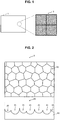
- FIG. 1 is an explanatory diagram schematically illustrating the diffuser plate according to the present embodiment.
- FIG. 2 is an explanatory diagram schematically illustrating part of unit cells that constitute the diffuser plate according to the present embodiment.
- FIG. 3A to FIG. 4B are explanatory diagrams illustrating examples of a state of the boundary between microlenses adjacent to each other in a unit cell according to the present embodiment.
- FIG. 5 is an explanatory diagram schematically illustrating the diffuser plate according to the present embodiment.
- FIG. 6A to FIG. 7B are explanatory diagrams for describing location of unit cells in the diffuser plate according to the present embodiment.
- the diffuser plate 1 is a microlens array diffuser plate in which a microlens group composed of a plurality of microlenses has been located on a substrate.
- a diffuser plate 1 includes a plurality of unit cells 3 as schematically illustrated in FIG. 1 .
- a layout pattern (location pattern) of a plurality of microlenses provided in the unit cells 3 is continuous in the sequence direction of the unit cells (in other words, the array sequence direction), as schematically illustrated in the right diagram in FIG. 1 .
- FIG. 1 presents an illustration using a case where the unit cells 3 that constitute the diffuser plate 1 have a rectangular shape as an example, whilst the shape of the unit cells 3 is not limited to that illustrated in FIG. 1 , but should only be a shape that can fill a plane leaving no space, such as an equilateral triangular shape or a regular hexagonal shape, for example.
- the number of the unit cells 3 that constitute the diffuser plate 1 according to the present embodiment is not particularly limited, but it is preferable that the diffuser plate 1 includes at least two or more unit cells 3.
- FIG. 2 is an explanatory diagram schematically illustrating a structure of part of the unit cells 3 according to the present embodiment.
- the unit cell 3 according to the present embodiment has a transparent substrate 10 and a microlens group 20 formed on a surface of the transparent substrate 10.
- the transparent substrate 10 is a substrate made of a material that can be assumed as transparent in a wavelength band of light that enters into the diffuser plate 1 according to the present embodiment. It is preferable that such a substrate is formed using an inorganic material having high light resistance.
- the inorganic material having high light resistance can include publicly-known optical glass such as quartz glass, borosilicate glass, and white plate glass, whilst it is preferable to use glass containing silicon as a principal component, in which an alkaline component content is less than or equal to 20 mass %.
- the transparent substrate 10 is a rectangle as an example
- the shape of the transparent substrate 10 is not limited to the rectangle, but may have an arbitrary shape, depending on the shape of a display device, a projection device, a lighting device, or the like, for example, in which the diffuser plate 1 is provided.
- the microlens group 20 composed of a plurality of microlenses 21 is formed on a surface of the transparent substrate 10. Since an essential usage of the diffuser plate is to diffuse light, it is preferable for the microlenses 21 that constitute the unit cell 3 that a light outgoing surface is entirely composed of concave lenses, as schematically illustrated at the bottom of FIG. 2 . This is because, in the case where the light outgoing surface of the diffuser plate is composed of convex lenses, a light collecting portion is created at a focal point, which can cause problems in installation restrictions and safety.
- the respective microlenses 21 are not identical in radius of curvature and vertex-to-vertex pitch, and have variations in a certain range, and thus, the focal length also has a certain distribution.
- the focal point becomes an imaginary point, whilst it is preferable that the focal point of each of the microlenses 21 is present in a region adjacent to the transparent substrate 10 that constitutes the diffuser plate 1 since the light intensity density is large at the focal point. This is because, in the case where the focal point of each of the microlenses 21 is present at a place away from the transparent substrate 10, restrictions on an optical system may occur, such as an inability to locate various components at the focal point.
- the respective microlenses 21 that constitute the unit cell 3 are arranged so as to satisfy three conditions indicated below.
- “irregular” mentioned in (2) above means that regularity concerning the location of the microlenses 21 does not exist practically, in an arbitrary region of the microlens group 20 in the diffuser plate 1. Thus, even if a certain kind of regularity exists in the location of the microlenses 21 at a microscopic region in an arbitrary region, the arbitrary region having no regularity in the location of the microlenses 21 as a whole is assumed to be determined as "irregular".
- all the ridge lines between the microlenses 21 adjacent to each other are nonparallel to each other and are nonparallel to the transparent substrate 10. This is because, in the case where ridge lines parallel to each other exist between the microlenses 21, diffracted light components will be increased.
- the "ridge line” shall refer to a linear region, present in an adjacent lens boundary portion to which the plurality of microlenses 21 are adjacent, in which the radius of curvature of the microlenses 21 changes drastically.
- the width of such a ridge line is usually approximately smaller than or equal to the wavelength of light, and the width of this ridge line is controlled by a process condition such as etching such that diffracted light has an appropriate magnitude.
- nonparallel shall include a case where at least one of two lines to be determined whether they are parallel or not is a curve.
- a microlens region surrounded by the adjacent microlenses 21 is a polygon as seen from the direction of an optical axis of the microlenses as illustrated in FIG. 3A and FIG. 3B , and each side of the polygon is a curve as seen from a cross-section of the microlens.
- the length of at least one of the sides of the unit cell 3 including the microlenses 21 that satisfy the above-described three conditions is an integer multiple of an average pitch of the microlenses 21 (for example, an average value of vertex-position-to-vertex-position distances of the respective microlenses 21) included in the unit cell 3.
- the cycle of the unit cells 3 in the diffuser plate 1 according to the present embodiment is a cycle in which the length of at least one of the sides of the unit cell 3 becomes an integer multiple of the average pitch of the microlenses 21.
- each of the adjacent microlenses 21 in the microlens group 20 is determined so as to satisfy the conditions as described above, and is not completely random.
- the half lens portion in the present embodiment refers to a region in which a change in radius of curvature of the microlenses 21 is relatively gentle such that the width of the ridge line becomes more than or equal to 10 ⁇ m.
- such a half lens portion also includes a half lens portion whose curvature has different signs in orthogonal directions like a saddle shape.
- An antireflection layer 30 may be formed on a front surface and a rear surface of the diffuser plate 1 according to the present embodiment (in other words, a surface of the microlenses 21 and a surface of the transparent substrate 10 at a side where the microlens group 20 is not arranged) for the purpose of increasing transmittance and preventing reflection stray light or the like, as schematically illustrated in FIG. 5 .
- an antireflection layer 30 by using a general dielectric such as SiO 2 , Al 2 O 3 , MgF 2 , CeO 2 , TiO 2 , Ta 2 O 5 , Nb2O 5 , Y 2 O 3 , Tb 2 O 3 , ZnS, or ZrO 2 , for example, by a publicly-known method such as vapor deposition or sputtering.
- a material having high light resistance such as Ta 2 O 5 , Nb 2 O 5 , or SiO 2 , for example, even if incoming light is light having a high optical density, such as high-power laser, it is possible to produce sufficient effects without degradation by such light.
- the antireflection layer 30 as a multilayered structure in which materials having high light resistance, such as Ta2O 5 , Nb 2 O 5 , and SiO 2 , for example, are laminated one upon another, it is possible to achieve still higher light resistance.
- the film thickness of such an antireflection layer 30 is not particularly limited, but may be appropriately set depending on the use of the diffuser plate 1, the optical density of incoming light, and the like.
- the film thickness of the antireflection layer 30 may differ at the central portion and the peripheral portion of the microlenses 21 due to the presence of unevenness of the microlenses 21 at the surface of the diffuser plate 1, and thus, it is preferable to form the antireflection layer 30 taking this into consideration.
- the incoming angle of incoming light differs at the central portion and the peripheral portion of the microlenses 21, it is more preferable to exercise ingenuity such as taking an assumed angular range wider than usual by design.
- the antireflection layer 30 provided on the surface of the microlenses 21 may be an antireflection structure formed on the surface of the microlens group 20 (which is also the surface of the microlenses 21) and composed of fine concavities and convexities (the so-called moth-eye structure) having sizes smaller than or equal to the wavelength of light. Since the inclination of the surface of the microlenses 21 becomes large particularly in the case of achieving a diffusion property in which the diffusion angle exceeds 10 degrees, the moth-eye structure in which the dependence of reflectivity on incoming angle is small is advantageous as compared with the multilayered structure described above.
- the above-described antireflection structure is a structure that is provided anisotropically within the surface of the microlenses 21 and has fine concavities and convexities having pitches of smaller than or equal to 300 nm.
- both of the diffusion effect exerted by lens elements (the microlenses 21) and diffracted light components resulting from the cyclic sequence of the microlenses 21 are superimposed to be outgoing light.
- the diffracted light components are a discrete distribution relative to angles, and the peak intensities of the diffracted light components become smaller in inverse proportion to the diffraction order m.
- these discrete diffraction components are buried in diffused light and cannot be identified as they are. Therefore, suppression of an adverse effect caused by the diffraction is performed by adding random irregular components to the cyclic location to make the diffraction peak smaller.
- the peak intensity of the diffracted light component also depends on incoming light conditions such as the incoming light diameter. For example, in the case where light with an incoming light diameter having a size approximately the same as the size of the microlenses 21 enters into a microlens 21, only little light enters into a microlens 21 adjacent to the microlens 21 into which the light has entered even if the microlens group 20 is regularly located, so that diffracted light hardly occurs.
- FIG. 6A to FIG. 6C Examples in which the outgoing light distribution of the microlens array having an irregular location was simulated by a commercially-available electromagnetic field simulator are illustrated in FIG. 6A to FIG. 6C .
- a pitch p of the microlenses 21 (which is also the diameter of the microlenses) in the microlens array is set at 82 ⁇ m
- the size of the rectangular microlens array is set at 738 ⁇ m ⁇ 710 ⁇ m (the length of the diagonal line: about 1024 ⁇ m).
- the diffraction angle resulting from the unit cell array (the diffraction angle between the unit cells 3) is considered.
- each of luminescent spots in diffracted light through the lens array as described earlier (in other words, each of luminescent spots in diffracted light obtained by diffraction within the unit cells 3) are separated further discretely by sub-diffraction peaks obtained by the unit cell array as described above. Consequently, clarity of luminescent spots in the diffused light will be reduced by such sub-diffracted light peaks.
- a phenomenon in which diffracted light obtained by diffraction within the unit cells 3 (hereinbelow, also referred to as main diffracted light) as described above is separated by sub-diffracted light causes the diffracted light luminescent spots in the diffused light to become smaller as the conditions transition from FIG. 6A to FIG. 6C .
- the diffraction angle obtained by the unit cells is very small, luminescent spots of the sub-diffraction component do not raise any problem in actual use of the diffuser plate 1 according to the present embodiment. Consequently, by causing sub-diffracted light obtained by the unit cells 3 to occur appropriately, it is possible to reduce the peak intensity of main diffracted light as described with reference to FIG. 6A to FIG. 6C .
- the intensity of sub-diffracted light is determined by the relationship between the unit cells 3 and the magnitude of incoming light.
- the unit cell 3 is larger than incoming light, sub-diffracted light resulting from the cyclic structure of the unit cells 3 will not occur in general.
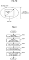
- the diameter in a direction in which such a full width at half maximum is minimized is defined as an "incoming light diameter" as illustrated in FIG. 7B .
- the unit cell 3 is assumed as being rectangular such as a rectangle or a square, and the length of the diagonal line of the unit cells 3 is defined as a "unit cell size".
- the unit cell size is smaller than the incoming light diameter as illustrated in FIG. 7B , sub-diffracted light resulting from diffraction between the unit cells 3 occurs, and it is possible to reduce the peak intensity of main diffracted light resulting from the lens array (in other words, resulting from diffraction within the unit cells 3).
- the diffuser plate 1 even if light that enters into the diffuser plate 1 is laser light, it is considered that the incoming light diameter as illustrated in FIG. 7B is at most approximately 3 mm. Consequently, if the unit cell size as illustrated in FIG 7B is smaller than or equal to 3 mm, it is possible to use the diffuser plate 1 according to the present embodiment for any laser light source.
- the microlens array diffuser plate 1 includes two or more unit cells 3, and each of the unit cells 3 has the microlens group 20 composed of the plurality of microlenses 21.
- the microlenses 21 included in each of the unit cells 3 are continuously set in array, the ridge lines between the respective microlenses 21 are nonparallel to each other, and are also nonparallel to the transparent substrate 10. Accordingly, the diffuser plate 1 according to the present embodiment can suppress the diffracted light components in diffused light, and exhibits an excellent diffusion property.
- the diffuser plate 1 according to the present embodiment has been described above in detail with reference to FIG. 1 to FIG. 7B .
- FIG. 8 is a flowchart illustrating an example of a flow of the manufacturing method of the diffuser plate according to the embodiment.
- FIG. 9 and FIG. 10 are explanatory diagrams for describing the manufacturing method of the diffuser plate according to the present embodiment.
- the diffuser plate 1 it is possible to manufacture the diffuser plate 1 according to the present embodiment by transferring a pattern made of an organic material, such as photoresist, for example, to a substrate by dry etching, as will be described below.
- a pattern made of an organic material such as photoresist, for example
- step S101 applying resist onto the predetermined transparent substrate 10 is carried out first (step S101).
- a fluorine-based etching gas such as CF 4 , SF 6 , or CHF 3
- step S103 a stepper exposure is carried out on the transparent substrate 10 on which the resist has been applied.
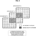
- pattern joints having a width of at most approximately several micrometers occur between basic cells depending on the positional accuracy in stepping, whilst it is possible to prevent these pattern joints from occurring by moving an exposure shot at the unit cell interval and performing an exposure with patterns overlapping, as schematically illustrated in FIG. 9 .
- the amount of exposure by one exposure is set at a half of a desired amount of exposure, it is possible to achieve the desired amount of exposure by four exposures.
- step S105 the resist pattern on which the stepper exposure has been terminated is developed. Accordingly, a desired microlens pattern is formed on the resist applied onto the transparent substrate 10.
- step S107 dry etching is carried out on the transparent substrate 10 on which development has been terminated, by utilizing a fluorine-based etching gas as described above (step S107). Accordingly, the microlens pattern formed on the resist is transferred to the transparent substrate 10.
- step S109 Thereafter, by using a dielectric as described above, AR coating is performed through vapor deposition or sputtering on the front surface and the rear surface of the transparent substrate 10 on which the microlens pattern has been formed to form the antireflection layer 30 (step S109).
- an antireflection structure composed of concavities and convexities having sizes smaller than or equal to the wavelength of light may be formed as the antireflection layer 30 on the surface of the microlenses.
- the diffuser plate 1 is produced by forming a resist pattern having a lens curved surface on the transparent substrate 10 such as a glass substrate by a gray scale exposure, and then performing dry etching on such a resist pattern to transfer the lens shape onto the transparent substrate 10.
- a lens-like resist pattern shape to be transferred to the transparent substrate 10 is determined taking not only conditions of the gray scale exposure but also conditions of the dry etching into consideration.
- Such a phenomenon means that the radius of curvature of microlenses made of photoresist obtained by the gray scale exposure can be adjusted by etching within the range of 70 to 170%.
- the shape of the resist pattern formed by the gray scale exposure is determined while taking into consideration the lens pattern of the transparent substrate 10 which is a final completed body of the diffuser plate and a shape deformation through the above-described etching. Specifically, when expressing the etching selection ratio as ⁇ and the depth (which is also a sag amount) of the respective microlenses 21 as S, the depth of the microlenses 21 actually formed on the transparent substrate 10 becomes approximately ⁇ S. In addition, when assuming the radius of curvature of the resist pattern as R, the radius of curvature after etching becomes R/ ⁇ .
- FIG. 10 illustrates results obtained by actually measuring the shape of the resist patterns formed in the case where the etching selection ratio is set at 0.6 and 1.7.
- the shape of the almost central portion (the shape in the vicinity of an A-A cut line at the top of FIG. 10 ) of a microlens array is actually measured with a laser confocal microscope.
- a resist design value and the shape of a transferred completed body do not always match with each other.
- FIG. 11 a designing method as illustrated in FIG. 11 is employed when manufacturing the diffuser plate according to the present embodiment.
- FIG. 11 is a flowchart illustrating an example of a flow of the designing method of the diffuser plate according to the present embodiment.
- change tolerances such as a radius-of-curvature changing range ⁇ R, a pitch changing range ⁇ p, and a lens-vertex-height changing range ⁇ h are set (step S205).
- layout of unit cells is carried out by utilizing a publicly-known lens location calculation algorithm (step S207).
- layout criteria are the conditions (1) to (3) as described earlier.
- step S207 In the case where the laid-out unit cells fail to satisfy all of the conditions (1) to (3) described above, the process returns to step S207, and layout of the unit cells is carried out again while changing the basic setting conditions within the range of change tolerances. On the other hand, in the case where the laid-out unit cells satisfy all of the conditions (1) to (3) described above, a temporary layout of unit cells is completed (step S211).
- the above-described etching selection ratio ⁇ is set (step S211). Thereafter, on the basis of the set etching selection ratio ⁇ , sag data (that is, height S) of the temporary layout is corrected to a value expressed by ⁇ S (step S215). Accordingly, a final layout of unit cells is completed (step S213).
- the manufacturing method as described above it is possible to manufacture the diffuser plate 1 according to the present embodiment with better productivity by utilizing an easier manufacturing process (a dry etching process).
- a Tempax glass substrate for example, is utilized as the transparent substrate 10, and a positive resist is applied onto this glass substrate.
- the film thickness of the resist is set at 11 ⁇ m so as to be larger than a sag depth of the microlenses 21 to be produced.
- a layout of the gray scale mask used shall be composed of a vertical and horizontal array sequence (that is, a basic cell) of the unit cells 3 having a rectangular shape of 737.6 ⁇ m wide ⁇ 709.6 ⁇ m depth.
- the unit cells 3 are designed such that, for example, the horizontal row of microlenses has an average pitch of 82 ⁇ m, and 9 (within a cell, a total of 100 or more) lenses are aligned so as not to be a discontinuous pattern in vertical and horizontal repetition.
- the locating condition of the respective microlenses within the unit cell 3 shall be such that the vertex in-plane position falls within a 42- ⁇ m in radius from the vertex of a hexagon, the changing range of the height position is smaller than or equal to 2 ⁇ m, and the boundaries between adjacent lenses are nonparallel to each other and also nonparallel to the substrate.
- R 752 ⁇ m is obtained after etching according to Expression 103 above.
- the location that satisfies the above-described conditions that is searched for and determined by uinsg the publicly-known lens location calculation algorithm shall be applied to the unit cells 3.
- an array sequence of sixteen unit cells 3 as described above in the horizontal direction ⁇ seventeen unit cells 3 in the vertical direction is set as the basic cell, and a step and repeat exposure is performed by using such a basic cell as an exposure unit.
- the resist shape obtained after development is uased as a mask, and dry etching is performed using a mixed gas of CF 4 and Ar as an etching gas.
- the etching speed is 0.5 ⁇ m/min for glass and 0.45 ⁇ m/min for resist as an example, and by performing etching deeper than the sag of the resist pattern, the microlens shape of the resist is transferred to the glass substrate.
- the antireflection layer 30 made of an Nb 2 O 5 /SiO 2 multilayered film, for example, is formed on the both surfaces of the glass substrate through vapor deposition or sputtering.
- the diffuser plate 1 according to the present embodiment described above is provided as appropriate in a device that needs to diffuse the light to achieve its function.
- the device that needs to diffuse the light to achieve its function is a display device such as various types of displays, a projection device such as a projector, and the like, for example.
- the diffuser plate 1 according to the present embodiment is also applicable to a backlight of a liquid crystal display device, and can also be used for optical shaping application. Further, the diffuser plate 1 according to the present embodiment can also be applied to various lighting devices.
- the device that needs to diffuse the light to achieve its function is not limited to the above examples, and the diffuser plate 1 according to the present embodiment can be applied to other publicly known devices, as long as it is a device that utilizes diffusion of light.
- diffuser plates having various diffusion full angles such as a diffusion full angle of approximately 1 degree to 30 degrees, are used.
- a diffuser plate having a diffusion full angle of less than 10 degrees is used, and in an application of obtaining a diffusion property similar to that of a phosphor film utilizing blue light and in an application of reducing speckles, a diffuser plate having a diffusion full angle of approximately 10 degrees to 30 degrees is used.
- a diffuser plate according to the second embodiment which will be described below in detail, additional conditions are added besides the above-described conditions (1) to (3) concerning each of the microlenses that constitute a unit cell to which attention has been paid in the diffuser plate according to the first embodiment, and thereby a more excellent diffusion property such that attenuation of diffused light becomes abrupt also in an angular region in which the diffused light intensity attenuates is achieved, in addition to suppression of diffraction components.
- the diffuser plate 1 according to the second embodiment of the present invention is a microlens array diffuser plate in which a microlens group composed of a plurality of microlenses is located on a substrate, similarly to the diffuser plate 1 according to the first embodiment.
- a diffuser plate 1 includes a plurality of unit cells 3 in the same manner as the diffuser plate 1 according to the first embodiment illustrated in FIG. 1 .
- a layout pattern (location pattern) of a plurality of microlenses provided in the unit cells 3 is continuous in the sequence direction (in other words, the array sequence direction) of the unit cells.
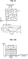
- FIG. 12 is an explanatory diagram schematically illustrating part of unit cells that constitute the diffuser plate according to the present embodiment.
- FIG. 13A is an explanatory diagram for describing variations in vertex-to-vertex distance in the microlens group according to the present embodiment
- FIG. 13B is an explanatory diagram for describing variations in radius of curvature in the microlens group according to the present embodiment.
- FIG. 14 is an explanatory diagram for describing an attenuation width in the diffuser plate according to the present embodiment
- FIG. 15A and FIG 15B are graphs illustrating the relationship between attenuation rates and variations in vertex-to-vertex distance and radius of curvature.
- FIG. 16 is an explanatory diagram for describing the relationship between diffusion full angles and attenuation rates in the diffuser plate.
- the unit cell 3 included in the diffuser plate 1 according to the present embodiment has the transparent substrate 10 and the microlens group 20 formed on a surface of the transparent substrate 10, similarly to the unit cell 3 according to the first embodiment illustrated in FIG. 2 .
- the transparent substrate 10 of the unit cells 3 according to the present embodiment has a similar structure to the transparent substrate 10 of the unit cells 3 according to the first embodiment and exerts similar effects, detailed description will be omitted below.
- the microlens group 20 composed of the plurality of microlenses 21 is formed on the surface of the transparent substrate 10, similarly to the first embodiment. Since an essential usage of the diffuser plate is to diffuse light, it is preferable that, for the microlenses 21 that constitute the unit cells 3, the light outgoing surface is entirely composed of concave lenses.
- the respective microlenses 21 are not identical in radius of curvature and vertex-to-vertex pitch, and the respective microlenses 21 have variations in a certain range, so that the focal length also has a certain distribution.
- the focal point is an imaginary point, whilst the light intensity density increases at the focal point, so that it is preferable that the focal point of each of the microlenses 21 is present in a region adjacent to the transparent substrate 10 that constitutes the diffuser plate 1.
- the respective microlenses 21 that constitute the unit cells 3 are arranged so as to satisfy three conditions (1) to (3) indicated below, similarly to the first embodiment.
- the ridge lines between the microlenses 21 adjacent to each other are entirely nonparallel to each other, and are nonparallel to the transparent substrate 10.
- an average value (average pitch) of the pitches of the repetition structures of the microlenses 21 (that is, the vertex-to-vertex distances between the microlenses 21 adjacent to each other in FIG. 12 ) shall be expressed as p
- an average value of the radii of curvature (average radius of curvature) of curves representing the shapes of the microlens 21 (that is, acurve corresponding to the sectional profile in FIG. 12 ) shall be expressed as R.
- the diffusion full angle (full width at half maximum) ⁇ of the microlens diffuser plate can be expressed as in Expression 201 below using the refractive index n of the microlenses 21, the average pitch (average vertex-to-vertex distance) p, and the average radius of curvature R.
- the average vertex-to-vertex distance p and the average radius of curvature R are determined on the basis of Expression 201 below such that the desired diffusion full angle ⁇ is obtained.
- the microlens group 20 has a uniform and regular sequence
- rays of diffused light from all the microlenses 21 that constitute the array match with each other, and a diffusion property having an abrupt attenuation property in which the central part is flat is obatained.
- this is not preferable as a diffuser plate. Consequently, similarly to the first embodiment, suppression of diffraction components is performed by introducing appropriate irregularity into the lens shapes and lens location. As a result, variations occur in values of vertex-to-vertex distance and radius of curvature as schematically illustrated in FIG. 13A and FIG. 13B .
- ⁇ R obtained by Expression 205 below is utilized as a variation degree of the radii of curvature from the average value in the present embodiment.
- abruptness in the diffusion property shall be expressed by an attenuation rate ⁇ expressed by Expression 207 below.
- ⁇ in Expression 207 below is the diffusion full angle, and corresponds to the full width at half maximum of the diffusion angle distribution curve as schematically illustrated in FIG. 14 .
- FIG. 207 is the diffusion full angle, and corresponds to the full width at half maximum of the diffusion angle distribution curve as schematically illustrated in FIG. 14 .
- an angular region from an angle at which the intensity becomes 90% of the maximum value to an angle at which the intensity becomes 10% of the maximum value shall be referred to as an attenuation range, and an average value of the extent (that is, an angular width) of such an attenuation range in the circumferential direction is expressed as an attenuation width ⁇ in Expression 207 below.
- an attenuation width ⁇ used in Expression 207 below is an average value of the extents of these two attenuation ranges (angular widths).
- a changing range dp of the vertex-to-vertex distance and a changing range dR of the radius of curvature shall be expressed by Expression 209 and Expression 211 below utilizing the variation degrees ⁇ p and ⁇ R given by Expression 203 and Expression 205 above.
- the attenuation width ⁇ can be expressed as Expression 213 below using Expression 201, Expression 209, and Expression 211 above.
- Expression 213 below can be expressed as Expression 215.
- the attenuation rate ⁇ defined by Expression 207 above can be expressed as Expression 217 below using Expression 215 below.
- the diffusion angle distribution curve is calculated using a commercially-available ray tracking simulator.
- a result of calculating the attenuation rate ⁇ from the obtained diffusion angle distribution curve thereafter is illustrated in FIG. 15B .
- the diffuser plate 1 for an application such as uniformly spreading light having large coherence, such as laser light, for example, to a phosphor surface.
- the attenuation rate ⁇ as described above influences the light conversion efficiency in phosphor, and is thus required to be usually less than or equal to 1, more preferably less than or equal to 0.9.
- the attenuation range extent ⁇ increases in proportion to the diffusion full angle ⁇ when the diffusion full angle ⁇ increases.
- the conversion efficiency of phosphor depends on the attenuation range extent ⁇ rather than the attenuation rate ⁇ , and as schematically illustrated in FIG. 16 , as the attenuation range extent ⁇ becomes wider, wasted light energy also increases. Consequently, in the case of achieving a diffuser plate having a larger diffusion full angle ⁇ , the required attenuation rate ⁇ becomes smaller.
- the diffusion full angles ⁇ become a same value
- the average vertex-to-vertex distance is restricted by the incoming light diameter, the sag in production, or the like
- the average radius of curvature is restricted by a resolution in the depth direction determined by a production method, or the like, in addition to the sag in production.
- the average vertex-to-vertex distance p falls within the range of 13 to 90 ⁇ m
- the average radius of curvature R falls within the range of 20 to 2000 ⁇ m.
- the diffuser plate 1 according to the present embodiment is paying attention to the fact that the attenuation property is related to two parameters including the distribution of microlens locations and the distribution of radii of curvature, and the ranges of these two parameters are defined. Accordingly, in the diffuser plate according to the present embodiment, it is possible to optimize the attenuation property while achieving reduction of diffraction components.
- the antireflection layer 30 may be formed on a front surface and a rear surface of the diffuser plate 1 according to the present embodiment (in other words, a surface of the microlenses 21 and a surface of the transparent substrate 10 at a side where the microlens group 20 is not arranged) for the purpose of increasing transmittance and preventing reflection stray light and the like. Since it is possible to provide, as such an antireflection layer 30, a layer similar to the antireflection layer 30 in the diffuser plate 1 according to the first embodiment, detailed description will be omitted below.
- the diffuser plate according to the present embodiment has been described above in detail with reference to FIG. 12 to FIG. 16 .
- the procedure of locating the microlenses 21 is not particularly limited.
- the vertex positions may be displaced within a range that satisfy the conditions (1) to (5) above, more preferably within a range that satisfy the conditions (1) to (6) above.
- a positional relationship that satisfies the conditions (1) to (5) above, more preferably a positional relationship that satisfies the conditions (1) to (6) above may be sequentially obtained using various computers without providing initial positions.
- NA of the stepper is 0.4 to 0.6, and the resist depth that can be exposed becomes about 15 ⁇ m.
- the sag depth is set at less than or equal to 15 ⁇ m.
- the array location according to the present embodiment allows the f-number to be precisely controlled by changing the sag depth even if the planar shapes are the same. That is, by changing the process time by a manufacturing method which will be described later, it is possible to achieve a desired f-number, and in addition, it is also possible to achieve high productivity.
- the f-number is smaller than or equal to 5.5, but even if the f-number is higher than that (for example, even if the f-number is approximately 8 to 60 for the purpose of making the light intensities of a laser array light source uniform, or the like), it is possible to manufacture the diffuser plate by shortening the process time by using a similar pattern.
- the diffuser plate 1 according to the present embodiment described above is provided as appropriate in a device that needs to diffuse the light to achive its function.
- the device that needs to diffuse the light to achieve its function is a display device such as various types of displays, a projection device such as a projector, and the like, for example.
- the diffuser plate 1 according to the present embodiment is also applicable to a backlight of a liquid crystal display device, and can also be used for optical shaping application. Further, the diffuser plate 1 according to the present embodiment can also be applied to various lighting devices.
- the device that needs to diffuse the light to achieve its function is not limited to the above examples, and the diffuser plate 1 according to the present embodiment can be applied to other publicly known devices, as long as it is a device that utilizes diffusion of light.
- the diffuser plate according to the present invention will be described in detail, with Examples and Comparative Examples. Note that the Examples described below are mere examples of the diffuser plate according to the present invention, and the diffuser plate according to the present invention is not limited to the following examples.
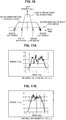
- FIG. 17A only in the case where the incoming light diameter is 650 ⁇ m, it is understood that sudden intensity changes within a range of a diffusion angle ( ⁇ 1 degree from central angle) that are not recognized in the cases of the other incoming light diameters ( FIG. 17B , FIG. 17C, FIG. 17D ) occur. This is because, at the incoming light diameter of 650 ⁇ m, sub-diffraction through the unit cells 3 does not sufficiently occur because of the presence of most of incoming light components within the unit cell size, and main diffracted light is output without being separated by sub-diffracted light.
- FIG. 17A and FIG 17D it is understood that sub-diffracted light as described earlier occurs because the unit cell size becomes smaller than or equal to the incoming light diameter, and sudden intensity changes as markedly monitored in FIG. 17A are relaxed.
- FIG. 18 illustrates conditions of diffuser plate models for which simulation is performed as a table, and obtained diffused light distributions are illustrated in FIG. 19A and FIG. 19B.
- FIG. 19A is a simulation result in the case where the variation degree ⁇ R of the radius of curvature is ⁇ 10%
- FIG. 19B is a simulation result in the case where the variation degree ⁇ R of the radius of curvature is ⁇ 20%.
- the attenuation rates ⁇ calculated from the results illustrated in FIG. 19A and FIG. 19B are shown together in the table illustrated in FIG. 18 .
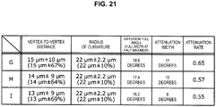
- FIG. 21 shows three types of conditions as illustrated in FIG. 21 . Obtained values of diffusion full angle, attenuation width, and attenuation rate are illustrated together in FIG. 21 .
- FIG. 22 the diffusion property of the obtained diffuser plate is illustrated in FIG. 22 . As is apparent from FIG. 21 and FIG.
- the attenuation rate can be 0.65 by setting the vertex-to-vertex distances at 15 ⁇ m ⁇ 10 ⁇ m (variation range: ⁇ 0.67) and the radii of curvature at 22 ⁇ m ⁇ 2.2 ⁇ m (variation width: ⁇ 0.10).
- a location state of the microlenses in such a case is illustrated in FIG. 23 .
Landscapes
- Physics & Mathematics (AREA)
- General Physics & Mathematics (AREA)
- Optics & Photonics (AREA)
- Engineering & Computer Science (AREA)
- General Engineering & Computer Science (AREA)
- Chemical & Material Sciences (AREA)
- Inorganic Chemistry (AREA)
- Optical Elements Other Than Lenses (AREA)
Abstract
Description
- The present invention relates to a diffuser plate, a designing method of the diffuser plate, a manufacturing method of the diffuser plate, a display device, a projection device, and a lighting device.
- A diffuser plate that scatters incoming light to various directions is widely utilized in various devices, for example, a display device such as a display, a projection device such as a projector, and various types of lighting devices. An incoming light diffusing mechanism in this diffuser plate is roughly classified into a mechanism that utilizes light refraction resulting from the surface shape of the diffuser plate and a mechanism that utilizes scattering by a substance existing inside a bulk body and having different refractive index from the circumference. One of the diffuser plates which utilize the light refraction resulting from the surface shape is what is called a microlens array diffuser plate including a plurality of microlenses having sizes of approximately several tens of micrometers and located on the surface of the bulk body.
- For a microlens array diffuser plate, various methods of suppressing occurrence of diffracted light by making the lens shape or lens location irregular have been proposed as in
Patent Literature 1 andPatent Literature 2 below, for example.Patent Literature 1 below discloses a diffuser plate for a reticle, and such a diffuser plate is designed to have variations in pitches and heights of microlenses. Specifically,Patent Literature 1 below discloses that a microlens pitch P is set at 8 µm ≤ P ≤ 30 µm and a microlens height H is set at 0.01×P ≤ H ≤ 0.1×P. In addition,Patent Literature 2 below discloses a microlens array in which a plurality of microlenses are located irregularly, and discloses that boundary regions of the plurality of microlenses are composed of a surface of a curvature having a different sign from that of a plane curvature of the microlenses. - In the case of actually manufacturing a structure of irregular location as described above, it is general to perform drawing by laser or an electron beam in production of a transfer mold or a photomask. On this occasion, in the case where the entire surface of a drawing region is a pattern having no repetition, there is a problem in that the amount of data becomes enormous. In addition, also when evaluating a drawn product, there is also a problem in that the production cost increases, such as, for example, requiring an enormous time for overall evaluation as a result of an inability to narrow down evaluation spots because the pattern has no repetition.
- In order to resolve the problems in productivity as described above,
Patent Literature 3 below, for example, discloses a manufacturing method of a focusing screen that performs an exposure of a large area by a step and repeat method using a reticle pattern composed of a random pattern. ThisPatent Literature 3 mentions preventing the pattern on the peripheral portion of the reticle from becoming discontinuous at joints. In addition, thisPatent Literature 3 also mentions suppression of diffracted light components while paying attention to functional properties as a focus plate, such as bokeh and brightness. -
- Patent Literature 1:
JP H3-192232A - Patent Literature 2:
JP 2007-108400A - Patent Literature 3:
JP S59-208536A - Here, a focusing screen (that is, a focus plate) manufactured by a manufacturing method as disclosed in
Patent Literature 3 above can achieve desired properties in the case where light enters across a wide region of the focus plate. However, if an attempt is made to apply such a manufacturing method to a microlens array diffuser plate, there is a problem in that it is difficult to obtain desired diffused light with respect to light that enters into a narrow region like a spot, such as laser light, for example. - In the case where spot-like incoming light as described above enters, particularly in the case where laser light enters, coherence of incoming light increases. Thus, not only the influence of the lens location but also the influence of the boundary portion between lenses is not negligible for suppression of diffracted light components, and in addition, only a lens portion existing in an irradiated spot exerts an influence upon outgoing light. From these perspectives, optimization of a microlens array structure different from the focus plate is important. Further, in order to retain durability even for high light intensity density in the spot, it is important to form the whole diffuser plate including the lens portion by using an appropriate material. However,
Patent Literature 3 above fails to disclose an influence exerted by restrictions in the manufacturing process resulting from the material of the diffuser plate upon the microlens structure. - Therefore, the present invention was made in view of above-described problems, and an object of the present invention is to provide a diffuser plate that exhibits an excellent diffusion property, has excellent durability with respect to light having large coherence, and can be manufactured with better productivity, a designing method of the diffuser plate, and a manufacturing method of the diffuser plate, as well as a display device, a projection device, and a lighting device in which such a diffuser plate is used.
- To solve the above-described problem, according to an aspect of the present invention, there is provided a microlens array diffuser plate including a microlens group positioned on a surface of a transparent substrate. The diffuser plate includes two or more unit cells that are continuously set in array, the unit cell includes a plurality of microlenses positioned on the surface of the transparent substrate, and ridge lines between the microlenses adjacent to each other are nonparallel to each other, and are nonparallel to the transparent substrate.
- It is preferable that a vertex-to-vertex distance of the microlenses that are adjacent to each other and that consitute the unit cell is included in a range of ±60% from an average value, and a radius of curvature of each of the microlenses that constitute the unit cell is included in a range of ±20% from an average value.
- It is preferable that, when expressing a variation degree from an average value of vertex-to-vertex distances of the microlenses that are adjacent to each other and that constitute the unit cell as σp, and expressing a variation degree from an average value of radii of curvature of the microlenses that are adjacent to each other and that constitute the unit cell as σR, (Expression 1) below is obtained.
[Math. 1]
- It is preferable that a length of a diagonal line of the unit cell is smaller than or equal to 3 mm.
- It is preferable that a length of at least one of sides of the unit cell is an integer multiple of an average pitch of the microlenses included in the unit cell.
- It is preferable that the number of microlenses included in the unit cell is at least 9 or more.
- It is preferable that, in the unit cell, a boundary portion between the microlenses adjacent to each other is not flat.
- It is preferable that a half lens is arranged in at least part of the boundary portion.
- The microlenses may have polygonal shapes.
- It is preferable that the microlenses are concave lenses.
- The transparent substrate may be made of an inorganic material.
- The inorganic material may be glass containing silicon as a principal component, in which an alkaline component content is less than or equal to 20%.
- The diffuser plate may include an antireflection layer on a surface of the microlenses and a surface of the transparent substrate on which the microlens group is not arranged.
- The antireflection layer may be a multilayered structure composed of Nb2O5 and SiO2.
- The antireflection layer provided on the surface of the microlenses may be an antireflection structure composed of concavities and convexities that have sizes smaller than or equal to a wavelength of light and that are formed on the surface of the microlens group.
- The antireflection structure may be a structure provided anisotropically in the surface of the microlenses, in which the concavities and convexities have pitches of smaller than or equal to 300 nm.
- To solve the above-described problem, according to another aspect of the present invention, there is provided adesigning method of a microlens array diffuser plate including a microlens group positioned on a surface of a transparent substrate. A radius of curvature of each of microlenses that constitute the microlens group is determined on a basis of a product of a reciprocal of an etching selection ratio between the transparent substrate and a resist and a radius of curvature developed on the resist.
- To solve the above-described problem, according to another aspect of the present invention, there is provided a manufacturing method of the diffuser plate, the manufacturing method including: a step of laminating a resist on the transparent substrate; a step of exposing the resist with a gray scale mask having a transmittance distribution; and a step of performing dry etching on the developed transparent substrate by using a fluorine-based gas such that a desired lens shape is obtained.
- In the step of performing dry etching, a radius of curvature of each of the microlenses that constitute the microlens group may be determined on a basis of a product of a reciprocal of an etching selection ratio between the transparent substrate and the resist and a radius of curvature developed on the resist.
- To solve the above-described problem, according to another aspect of the present invention, there is provided a display device including the diffuser plate.
- To solve the above-described problem, according to another aspect of the present invention, there is provided a projection device including the diffuser plate.
- To solve the above-described problem, according to another aspect of the present invention, there is provided a lighting device inlcuding the diffuser plate.
- According to the present invention as described above, it is possible to manufacture, with better productivity, a diffuser plate that exhibits an excellent diffusion property and has excellent durability with respect to light having large coherence, and it is possible to provide a display device, a projection device, and a lighting device in which such a diffuser plate is used.
-
- [
FIG. 1] FIG. 1 is an explanatory diagram schematically illustrating a diffuser plate according to a first embodiment of the present invention. - [
FIG. 2] FIG. 2 is an explanatory diagram schematically illustrating part of unit cells that constitute the diffuser plate according to the embodiment. - [
FIG. 3A] FIG. 3A is an explanatory diagram schematically illustrating examples of a state of a boundary between adjacent microlenses in a unit cell according to the embodiment. - [
FIG. 3B] FIG. 3B is an explanatory diagram illustrating an example of a state of a boundary between adjacent microlenses in a unit cell according to the embodiment. - [
FIG. 4A] FIG. 4A is an explanatory diagram illustrating an example of a state of a boundary between adjacent microlenses in a unit cell according to the embodiment. - [
FIG.4B] FIG. 4B is an explanatory diagram illustrating an example of a state of a boundary between adjacent microlenses in a unit cell according to the embodiment. - [
FIG. 5] FIG. 5 is an explanatory diagram schematically illustrating a diffuser plate according to the embodiment. - [
FIG. 6A] FIG. 6A is an explanatory diagram for describing location of unit cells in the diffuser plate according to the embodiment. - [
FIG. 6B] FIG. 6B is an explanatory diagram for describing location of unit cells in the diffuser plate according to the embodiment. - [
FIG 6C] FIG. 6C is an explanatory diagram for describing location of unit cells in the diffuser plate according to the embodiment. - [
FIG. 7A] FIG. 7A is an explanatory diagram for describing location of unit cells in the diffuser plate according to the embodiment. - [
FIG. 7B] FIG. 7B is an explanatory diagram for describing location of unit cells in the diffuser plate according to the embodiment. - [
FIG. 8] FIG. 8 is a flowchart illustrating an example of a flow of a manufacturing method of the diffuser plate according to the embodiment. - [
FIG. 9] FIG. 9 is an explanatory diagram for describing the manufacturing method of the diffuser plate according to the embodiment. - [
FIG. 10] FIG. 10 is an explanatory diagram for describing the manufacturing method of the diffuser plate according to the embodiment. - [
FIG. 11] FIG. 11 is a flowchart illustrating an example of a flow of a designing method of the diffuser plate according to the embodiment. - [
FIG 12] FIG. 12 is an explanatory diagram schematically illustrating part of unit cells that constitute a diffuser plate according to a second embodiment of the present invention. - [
FIG. 13A] FIG. 13A is an explanatory diagram for describing variations in vertex-to-vertex distance in a microlens group according to the embodiment. - [
FIG. 13B] FIG. 13B is an explanatory diagram for describing variations in radius of curvature in the microlens group according to the embodiment. - [
FIG. 14] FIG. 14 is an explanatory diagram for describing an attenuation range in the diffuser plate according to the embodiment. - [
FIG. 15A] FIG. 15A is a graph illustrating the relationship between attenuation rates and variations in vertex-to-vertex distance and radius of curvature. - [
FIG. 15B] FIG. 15B is a graph illustrating the relationship between attenuation rates and variations in vertex-to-vertex distance and radius of curvature. - [
FIG. 16] FIG. 16 is an explanatory diagram for describing relationships between diffusion full angles and attenuation rates in the diffuser plate. - [
FIG. 17A] FIG. 17A is a graph illustrating results of examples concerning the diffuser plate according to the first embodiment of the present invention. - [
FIG. 17B] FIG. 17B is a graph illustrating results of examples concerning the diffuser plate according to the first embodiment of the present invention. - [
FIG. 17C] FIG. 17C is a graph illustrating results of examples concerning the diffuser plate according to the first embodiment of the present invention. - [
FIG. 17D] FIG 17D is a graph illustrating results of examples concerning the diffuser plate according to the first embodiment of the present invention. - [
FIG. 18] FIG. 18 is a table illustrating results of examples concerning the diffuser plate according to the second embodiment of the present invention. - [
FIG. 19A] FIG. 19A is a graph illustrating results of examples concerning the diffuser plate according to the second embodiment of the present invention. - [
FIG. 19B] FIG. 19B is a graph illustrating results of examples concerning the diffuser plate according to the second embodiment of the present invention. - [
FIG. 20] FIG. 20 is a graph illustrating results of examples concerning the diffuser plate according to the second embodiment of the present invention. - [
FIG. 21] FIG. 21 is a table illustrating results of examples concerning the diffuser plate according to the second embodiment of the present invention. - [
FIG. 22] FIG. 22 is a graph illustrating results of examples concerning the diffuser plate according to the second embodiment of the present invention. - [
FIG. 23] FIG. 23 is an explanatory diagram illustrating an example of location of microlenses in the diffuser plate according to the second embodiment of the present invention. - Hereinafter, (a) preferred embodiment(s) of the present invention will be described in detail with reference to the appended drawings. Note that, in this specification and the appended drawings, structural elements that have substantially the same function and structure are denoted with the same reference numerals, and repeated explanation of these structural elements is omitted.
- Hereinbelow, a
diffuser plate 1 according to a first embodiment of the present invention will be described in detail with reference toFIG. 1 to FIG. 7B . -
FIG. 1 is an explanatory diagram schematically illustrating the diffuser plate according to the present embodiment.FIG. 2 is an explanatory diagram schematically illustrating part of unit cells that constitute the diffuser plate according to the present embodiment.FIG. 3A to FIG. 4B are explanatory diagrams illustrating examples of a state of the boundary between microlenses adjacent to each other in a unit cell according to the present embodiment.FIG. 5 is an explanatory diagram schematically illustrating the diffuser plate according to the present embodiment.FIG. 6A to FIG. 7B are explanatory diagrams for describing location of unit cells in the diffuser plate according to the present embodiment. - The
diffuser plate 1 according to the present embodiment is a microlens array diffuser plate in which a microlens group composed of a plurality of microlenses has been located on a substrate. Such adiffuser plate 1 includes a plurality ofunit cells 3 as schematically illustrated inFIG. 1 . In addition, between theunit cells 3, a layout pattern (location pattern) of a plurality of microlenses provided in theunit cells 3 is continuous in the sequence direction of the unit cells (in other words, the array sequence direction), as schematically illustrated in the right diagram inFIG. 1 . - Here,
FIG. 1 presents an illustration using a case where theunit cells 3 that constitute thediffuser plate 1 have a rectangular shape as an example, whilst the shape of theunit cells 3 is not limited to that illustrated inFIG. 1 , but should only be a shape that can fill a plane leaving no space, such as an equilateral triangular shape or a regular hexagonal shape, for example. - The number of the
unit cells 3 that constitute thediffuser plate 1 according to the present embodiment is not particularly limited, but it is preferable that thediffuser plate 1 includes at least two ormore unit cells 3. -
FIG. 2 is an explanatory diagram schematically illustrating a structure of part of theunit cells 3 according to the present embodiment. As schematically illustrated inFIG. 2 , theunit cell 3 according to the present embodiment has atransparent substrate 10 and amicrolens group 20 formed on a surface of thetransparent substrate 10. - The
transparent substrate 10 is a substrate made of a material that can be assumed as transparent in a wavelength band of light that enters into thediffuser plate 1 according to the present embodiment. It is preferable that such a substrate is formed using an inorganic material having high light resistance. Examples of the inorganic material having high light resistance can include publicly-known optical glass such as quartz glass, borosilicate glass, and white plate glass, whilst it is preferable to use glass containing silicon as a principal component, in which an alkaline component content is less than or equal to 20 mass %. By using such an inorganic material, it is possible to eliminate degradation in diffusion property of the diffuser plate that would be caused by an alteration in material even in the case of particularly using high-power laser light as incoming light. AlthoughFIG. 2 presents an illustration using a case where thetransparent substrate 10 is a rectangle as an example, the shape of thetransparent substrate 10 is not limited to the rectangle, but may have an arbitrary shape, depending on the shape of a display device, a projection device, a lighting device, or the like, for example, in which thediffuser plate 1 is provided. - <
Microlens Group 20> - The
microlens group 20 composed of a plurality ofmicrolenses 21 is formed on a surface of thetransparent substrate 10. Since an essential usage of the diffuser plate is to diffuse light, it is preferable for themicrolenses 21 that constitute theunit cell 3 that a light outgoing surface is entirely composed of concave lenses, as schematically illustrated at the bottom ofFIG. 2 . This is because, in the case where the light outgoing surface of the diffuser plate is composed of convex lenses, a light collecting portion is created at a focal point, which can cause problems in installation restrictions and safety. In addition, in themicrolens group 20 according to the present embodiment, therespective microlenses 21 are not identical in radius of curvature and vertex-to-vertex pitch, and have variations in a certain range, and thus, the focal length also has a certain distribution. In the case of concave lenses, the focal point becomes an imaginary point, whilst it is preferable that the focal point of each of themicrolenses 21 is present in a region adjacent to thetransparent substrate 10 that constitutes thediffuser plate 1 since the light intensity density is large at the focal point. This is because, in the case where the focal point of each of themicrolenses 21 is present at a place away from thetransparent substrate 10, restrictions on an optical system may occur, such as an inability to locate various components at the focal point. - In addition, in the
microlens group 20 according to the present embodiment, therespective microlenses 21 that constitute theunit cell 3 are arranged so as to satisfy three conditions indicated below. - (1) The boundaries on the four sides of the
unit cell 3 shall be such that discontinuousness does not occur in the pattern in the array sequence. - (2) The planar position and height position of the vertex of each of the microlenses 21 (in other words, the lowest position of the depth of the concave lens) and ridge lines between the
microlenses 21 shall be made irregular such that diffraction is sufficiently suppressed. - (3) In order to suppress undiffused transmitted light, a non-lens region shall not exist between the
microlenses 21 adjacent to each other. - Here, "irregular" mentioned in (2) above means that regularity concerning the location of the
microlenses 21 does not exist practically, in an arbitrary region of themicrolens group 20 in thediffuser plate 1. Thus, even if a certain kind of regularity exists in the location of themicrolenses 21 at a microscopic region in an arbitrary region, the arbitrary region having no regularity in the location of themicrolenses 21 as a whole is assumed to be determined as "irregular". - In the
microlens group 20 according to the present embodiment located so as to satisfy the above-described three conditions, all the ridge lines between themicrolenses 21 adjacent to each other are nonparallel to each other and are nonparallel to thetransparent substrate 10. This is because, in the case where ridge lines parallel to each other exist between themicrolenses 21, diffracted light components will be increased. - Here, the "ridge line" shall refer to a linear region, present in an adjacent lens boundary portion to which the plurality of
microlenses 21 are adjacent, in which the radius of curvature of themicrolenses 21 changes drastically. The width of such a ridge line is usually approximately smaller than or equal to the wavelength of light, and the width of this ridge line is controlled by a process condition such as etching such that diffracted light has an appropriate magnitude. In addition, "nonparallel" shall include a case where at least one of two lines to be determined whether they are parallel or not is a curve. - Specifically, a microlens region surrounded by the
adjacent microlenses 21 is a polygon as seen from the direction of an optical axis of the microlenses as illustrated inFIG. 3A and FIG. 3B , and each side of the polygon is a curve as seen from a cross-section of the microlens. - In addition, it is preferable that the length of at least one of the sides of the
unit cell 3 including themicrolenses 21 that satisfy the above-described three conditions is an integer multiple of an average pitch of the microlenses 21 (for example, an average value of vertex-position-to-vertex-position distances of the respective microlenses 21) included in theunit cell 3. In other words, it is preferable that the cycle of theunit cells 3 in thediffuser plate 1 according to the present embodiment is a cycle in which the length of at least one of the sides of theunit cell 3 becomes an integer multiple of the average pitch of themicrolenses 21. - In this manner, each of the
adjacent microlenses 21 in themicrolens group 20 is determined so as to satisfy the conditions as described above, and is not completely random. - Note that, for the ridge lines between the
adjacent microlenses 21, it is possible to exercise further ingenuity in order to reduce diffracted light components. For example, it is also possible to make part of the ridge line have an irregular shape rather than a simple straight line or curve as schematically illustrated inFIG. 3A , and to locate a different shape such as a half lens portion on part of the ridge line as illustrated inFIG. 4A and FIG. 4B . Here, the half lens portion in the present embodiment refers to a region in which a change in radius of curvature of themicrolenses 21 is relatively gentle such that the width of the ridge line becomes more than or equal to 10 µm. In addition, such a half lens portion also includes a half lens portion whose curvature has different signs in orthogonal directions like a saddle shape. By making the ridge lines between themicrolenses 21 have a form as described above, it is possible to make the boundary portions between themicrolenses 21 adjacent to each other non-flat to disturb the phase of a diffraction wavefront occurring at the ridge line portion, and to prevent diffracted light components in a specific direction from occurring. - In addition, it is preferable that the number of the
microlenses 21 that constitute theunit cell 3 is 3×3 = 9 or more. This is derived from the fact that, in the case where incoming light equal in diameter to theunit cell 3 enters, the diffusion property does not change with respect to a displacement of an incoming light position if the average pitch of themicrolenses 21 is approximately smaller than or equal to 1/3 of the incoming light diameter. The relationship between the average pitch of themicrolenses 21 and the incoming light diameter will be described later in detail. - An
antireflection layer 30 may be formed on a front surface and a rear surface of thediffuser plate 1 according to the present embodiment (in other words, a surface of themicrolenses 21 and a surface of thetransparent substrate 10 at a side where themicrolens group 20 is not arranged) for the purpose of increasing transmittance and preventing reflection stray light or the like, as schematically illustrated inFIG. 5 . - It is possible to form such an
antireflection layer 30 by using a general dielectric such as SiO2, Al2O3, MgF2, CeO2, TiO2, Ta2O5, Nb2O5, Y2O3, Tb2O3, ZnS, or ZrO2, for example, by a publicly-known method such as vapor deposition or sputtering. Here, by forming theantireflection layer 30 using a material having high light resistance, such as Ta2O5, Nb2O5, or SiO2, for example, even if incoming light is light having a high optical density, such as high-power laser, it is possible to produce sufficient effects without degradation by such light. On this occasion, by forming theantireflection layer 30 as a multilayered structure in which materials having high light resistance, such as Ta2O5, Nb2O5, and SiO2, for example, are laminated one upon another, it is possible to achieve still higher light resistance. The film thickness of such anantireflection layer 30 is not particularly limited, but may be appropriately set depending on the use of thediffuser plate 1, the optical density of incoming light, and the like. - Note that, when forming the
antireflection layer 30 on thediffuser plate 1, the film thickness of theantireflection layer 30 may differ at the central portion and the peripheral portion of themicrolenses 21 due to the presence of unevenness of themicrolenses 21 at the surface of thediffuser plate 1, and thus, it is preferable to form theantireflection layer 30 taking this into consideration. In addition, since the incoming angle of incoming light differs at the central portion and the peripheral portion of themicrolenses 21, it is more preferable to exercise ingenuity such as taking an assumed angular range wider than usual by design. - In addition, the
antireflection layer 30 provided on the surface of themicrolenses 21 may be an antireflection structure formed on the surface of the microlens group 20 (which is also the surface of the microlenses 21) and composed of fine concavities and convexities (the so-called moth-eye structure) having sizes smaller than or equal to the wavelength of light. Since the inclination of the surface of themicrolenses 21 becomes large particularly in the case of achieving a diffusion property in which the diffusion angle exceeds 10 degrees, the moth-eye structure in which the dependence of reflectivity on incoming angle is small is advantageous as compared with the multilayered structure described above. From the perspective of reducing stray light and reflection, it is preferable that the above-described antireflection structure is a structure that is provided anisotropically within the surface of themicrolenses 21 and has fine concavities and convexities having pitches of smaller than or equal to 300 nm. - As is conventionally known, when light enters into a cyclic repetition structure, diffracted light occurs. When expressing the pitch of the repetition structure (repetition cycle) as p, a diffraction order (integer) as m, and the wavelength of incoming light as λ, a diffraction angle θ is given by Expression 101 below.
[Math. 2]
- In the case of a microlens array diffuser plate as receiving attention in the present embodiment, both of the diffusion effect exerted by lens elements (the microlenses 21) and diffracted light components resulting from the cyclic sequence of the
microlenses 21 are superimposed to be outgoing light. The diffracted light components are a discrete distribution relative to angles, and the peak intensities of the diffracted light components become smaller in inverse proportion to the diffraction order m. When becoming smaller than the intensity level of diffused light spread by the lens array, these discrete diffraction components are buried in diffused light and cannot be identified as they are. Therefore, suppression of an adverse effect caused by the diffraction is performed by adding random irregular components to the cyclic location to make the diffraction peak smaller. - In addition, the peak intensity of the diffracted light component also depends on incoming light conditions such as the incoming light diameter. For example, in the case where light with an incoming light diameter having a size approximately the same as the size of the
microlenses 21 enters into amicrolens 21, only little light enters into amicrolens 21 adjacent to themicrolens 21 into which the light has entered even if themicrolens group 20 is regularly located, so that diffracted light hardly occurs. On the other hand, in the case where incoming light having an incoming light diameter approximately the same as the size of themicrolenses 21 enters into amicrolens 21, a phenomenon in which the outgoing property changes is likely to occur depending on the relationship between the incoming light axis and the optical axis of themicrolens 21. - Examples in which the outgoing light distribution of the microlens array having an irregular location was simulated by a commercially-available electromagnetic field simulator are illustrated in
FIG. 6A to FIG. 6C . In such simulation, a pitch p of the microlenses 21 (which is also the diameter of the microlenses) in the microlens array is set at 82 µm, and the size of the rectangular microlens array is set at 738 µm × 710 µm (the length of the diagonal line: about 1024 µm). Then, how the outgoing light distribution including diffracted light is projected onto a screen which is a detector in the case where the incoming light diameter of light entering into such a microlens array is changed to 200 µm, 300 µm, and 650 µm is verified. InFIG. 6A to FIG. 6C , luminescent spots in the drawings indicate diffracted light caused by the microlens array. - As illustrated in
FIG. 6A , since diffracted light luminescent spots in diffused light are enlarged in the case where the size difference between the diameter (82 µm) of themicrolenses 21 and the incoming light diameter is relatively small, it is understood that it is preferable to decrease the diameter of the microlenses 21 (or increase the incoming light diameter) as is apparent fromFIG. 6B andFIG. 6C . Specifically, by setting the pitch of the microlens array at smaller than or equal to about 1/3 of the incoming light diameter, it is possible to reduce the influence caused by the luminescent spots as described above to a practically negligible level. - On the other hand, when actually manufacturing the microlens array, producing a photomask or mold for transfer is considered. In this case, in general, formation of the shapes of the
microlenses 21 is often performed by direct drawing with laser or an electron beam, whilst in order to reduce the amount of data to be produced, a technique like the so-called step and repeat that repeats theunit cell 3 having a relatively small area vertically and horizontally to form an array sequence and enlarges the array sequence to a desired size is also often adopted. When light enters into a microlens array having such an array structure, two types of diffracted light components composed of double repetition structures, one within theunit cells 3 and the other between theunit cells 3, will be produced. With respect to each diffraction angle, the diffraction angle within theunit cells 3 is determined by the pitch of the lens location, and the diffraction angle between theunit cells 3 is determined by the sizes of theunit cells 3. - The diffraction angle resulting from the unit cell array (the diffraction angle between the unit cells 3) is considered. For example, when assuming the pitch of the unit cell as 700 µm and the wavelength of incoming light as 450 nm, the angle (half angle) of first order diffracted light (diffracted light in the case where m=1) is 0.03 degree according to Expression (101) above. Consequently, even in the case where the diffusion angle (half angle) of the diffuser plate is approximately 3 degrees, (3/0.03)2 = 104 rays of diffracted light will occur in diffused light. Since the intensity of diffracted light rapidly decreases as the diffraction order m becomes higher (for example, when the diffraction order is m, the peak intensity becomes (2/π)m), approximately several tens of diffraction peaks will appear in the diffused light, actually. Hereinbelow, such diffracted light resulting from the unit cell array will be referred to as sub-diffracted light.
- On the other hand, each of luminescent spots in diffracted light through the lens array as described earlier (in other words, each of luminescent spots in diffracted light obtained by diffraction within the unit cells 3) are separated further discretely by sub-diffraction peaks obtained by the unit cell array as described above. Consequently, clarity of luminescent spots in the diffused light will be reduced by such sub-diffracted light peaks. A phenomenon in which diffracted light obtained by diffraction within the unit cells 3 (hereinbelow, also referred to as main diffracted light) as described above is separated by sub-diffracted light causes the diffracted light luminescent spots in the diffused light to become smaller as the conditions transition from
FIG. 6A to FIG. 6C . - Here, since the diffraction angle obtained by the unit cells is very small, luminescent spots of the sub-diffraction component do not raise any problem in actual use of the
diffuser plate 1 according to the present embodiment. Consequently, by causing sub-diffracted light obtained by theunit cells 3 to occur appropriately, it is possible to reduce the peak intensity of main diffracted light as described with reference toFIG. 6A to FIG. 6C . - The intensity of sub-diffracted light is determined by the relationship between the
unit cells 3 and the magnitude of incoming light. In the case where theunit cell 3 is larger than incoming light, sub-diffracted light resulting from the cyclic structure of theunit cells 3 will not occur in general. Here, considering the full width at half maximum of incoming light intensity as illustrated inFIG. 7A , the diameter in a direction in which such a full width at half maximum is minimized is defined as an "incoming light diameter" as illustrated inFIG. 7B . In addition, theunit cell 3 is assumed as being rectangular such as a rectangle or a square, and the length of the diagonal line of theunit cells 3 is defined as a "unit cell size". On this occasion, if the unit cell size is smaller than the incoming light diameter as illustrated inFIG. 7B , sub-diffracted light resulting from diffraction between theunit cells 3 occurs, and it is possible to reduce the peak intensity of main diffracted light resulting from the lens array (in other words, resulting from diffraction within the unit cells 3). - Here, even if light that enters into the
diffuser plate 1 is laser light, it is considered that the incoming light diameter as illustrated inFIG. 7B is at most approximately 3 mm. Consequently, if the unit cell size as illustrated inFIG 7B is smaller than or equal to 3 mm, it is possible to use thediffuser plate 1 according to the present embodiment for any laser light source. - As described above, the microlens
array diffuser plate 1 according to the present embodiment includes two ormore unit cells 3, and each of theunit cells 3 has themicrolens group 20 composed of the plurality ofmicrolenses 21. In addition, it is characterized in that themicrolenses 21 included in each of theunit cells 3 are continuously set in array, the ridge lines between therespective microlenses 21 are nonparallel to each other, and are also nonparallel to thetransparent substrate 10. Accordingly, thediffuser plate 1 according to the present embodiment can suppress the diffracted light components in diffused light, and exhibits an excellent diffusion property. - The
diffuser plate 1 according to the present embodiment has been described above in detail with reference toFIG. 1 to FIG. 7B . - Hereinbelow, an example of a manufacturing method of the
diffuser plate 1 according to the present embodiment will be described briefly with reference toFIG. 8 to FIG. 10 .FIG. 8 is a flowchart illustrating an example of a flow of the manufacturing method of the diffuser plate according to the embodiment.FIG. 9 andFIG. 10 are explanatory diagrams for describing the manufacturing method of the diffuser plate according to the present embodiment. - It is possible to manufacture the
diffuser plate 1 according to the present embodiment by transferring a pattern made of an organic material, such as photoresist, for example, to a substrate by dry etching, as will be described below. - In such a manufacturing method, applying resist onto the predetermined
transparent substrate 10 is carried out first (step S101). Here, in the manufacturing method as described below, since a fluorine-based etching gas such as CF4, SF6, or CHF3 is generally used as an etching gas, it is preferable to use, for thetransparent substrate 10, quartz glass or Tempax glass that does not contain Al2O3, an alkaline component such as alkali metal (or an alkaline component content of less than or equal to 20 mass %, more preferably less than or equal to 10 mass %) or the like that react with a fluorine-based etching gas as described above to turn into nonvolatile materials. For example, when performing dry etching on a glass substrate (for example,EAGLE XG (the name of a product made by Corning Incorporated) or the like) that contains 27% Al2O3 and does not contain alkali metal at all, by using a fluorine-based etching gas as described above, a problem will occur in that unetched microprojections of Al2O3 occur at the surface, resulting in reduced transmittance. - Subsequently, by using a gray scale mask, a stepper exposure is carried out on the
transparent substrate 10 on which the resist has been applied (step S103). - On this occasion, as schematically illustrated in
FIG. 9 , it is also possible to use an array of theunit cells 3 each of which are smaller than or equal to approximately 1 mm and which are further repeated vertically and horizontally, as a basic cell of approximately 1 to 20 mm, and to use such a basic cell as a repetition unit in a step and repeat exposure. In this case, pattern joints having a width of at most approximately several micrometers occur between basic cells depending on the positional accuracy in stepping, whilst it is possible to prevent these pattern joints from occurring by moving an exposure shot at the unit cell interval and performing an exposure with patterns overlapping, as schematically illustrated inFIG. 9 . On this occasion, in the case where the amount of exposure by one exposure is set at a half of a desired amount of exposure, it is possible to achieve the desired amount of exposure by four exposures. In addition, it is also possible to eliminate joints by performing a step and repeat exposure in such a manner that edges of adjacent basic cells overlap slightly (with a width of less than or equal to 500 nm, for example). In this case, a plurality of exposures become unnecessary. - Subsequently, the resist pattern on which the stepper exposure has been terminated is developed (step S105). Accordingly, a desired microlens pattern is formed on the resist applied onto the
transparent substrate 10. - Subsequently, dry etching is carried out on the
transparent substrate 10 on which development has been terminated, by utilizing a fluorine-based etching gas as described above (step S107). Accordingly, the microlens pattern formed on the resist is transferred to thetransparent substrate 10. - Thereafter, by using a dielectric as described above, AR coating is performed through vapor deposition or sputtering on the front surface and the rear surface of the
transparent substrate 10 on which the microlens pattern has been formed to form the antireflection layer 30 (step S109). In addition, by using a manufacturing method of a publicly-known moth-eye structure, an antireflection structure composed of concavities and convexities having sizes smaller than or equal to the wavelength of light may be formed as theantireflection layer 30 on the surface of the microlenses. - In this manner, the
diffuser plate 1 according to the present embodiment is produced by forming a resist pattern having a lens curved surface on thetransparent substrate 10 such as a glass substrate by a gray scale exposure, and then performing dry etching on such a resist pattern to transfer the lens shape onto thetransparent substrate 10. Here, a lens-like resist pattern shape to be transferred to thetransparent substrate 10 is determined taking not only conditions of the gray scale exposure but also conditions of the dry etching into consideration. - Here, the ratio between the etching speed for the resist in dry etching and the etching speed for the transparent substrate 10 (such as glass, for example) in the dry etching (= the etching speed for the transparent substrate/the etching speed for the resist) will be referred to as an "etching selection ratio". On this occasion, by regulating the flow rate of each etching gas in the dry etching step, it is possible to change the above-described etching selection ratio. Accordingly, it is possible to perform fine adjustment of the lens shape (for example, the radius of curvature of the microlenses 21) to be transferred.
- Specifically, in the case of using CF4, Ar, or O2 as an etching gas, the etching selection ratio as described above changes to 1.0 to 1.7 when the flow rate (= "flow of CF4 gas/flow of Ar gas") is changed within the range of 0.25 to 4. Further, when 3% to 10% O2 gas is added in this state, the etching selection ratio as described above can be reduced to 0.7 to 1.0. In this manner, it is possible to change the etching selection ratio to 0.7 to 1.7 depending on conditions of the etching gas. Such a phenomenon means that the radius of curvature of microlenses made of photoresist obtained by the gray scale exposure can be adjusted by etching within the range of 70 to 170%.
- The shape of the resist pattern formed by the gray scale exposure is determined while taking into consideration the lens pattern of the
transparent substrate 10 which is a final completed body of the diffuser plate and a shape deformation through the above-described etching. Specifically, when expressing the etching selection ratio as η and the depth (which is also a sag amount) of therespective microlenses 21 as S, the depth of themicrolenses 21 actually formed on thetransparent substrate 10 becomes approximately η×S. In addition, when assuming the radius of curvature of the resist pattern as R, the radius of curvature after etching becomes R/η. -
FIG. 10 illustrates results obtained by actually measuring the shape of the resist patterns formed in the case where the etching selection ratio is set at 0.6 and 1.7. In such measurement, the shape of the almost central portion (the shape in the vicinity of an A-A cut line at the top ofFIG. 10 ) of a microlens array is actually measured with a laser confocal microscope. As is apparent fromFIG. 10 , a resist design value and the shape of a transferred completed body do not always match with each other. - Therefore, a designing method as illustrated in
FIG. 11 is employed when manufacturing the diffuser plate according to the present embodiment. - Hereinbelow, an example of a designing method of the
diffuser plate 1 according to the present embodiment will be described briefly with reference toFIG. 11. FIG. 11 is a flowchart illustrating an example of a flow of the designing method of the diffuser plate according to the present embodiment. - In the designing method of the diffuser plate according to the present embodiment, first, basic design conditions such as a refractive index n of the
transparent substrate 10, a diffusion angle size θ to be achieved, and the pitch p of themicrolenses 21 are set (step S201). Thereafter, a radius of curvature R (n, θ, p) is calculated on the basis of Expression 103 below (step S203).
[Math. 3]
- Subsequently, in the designing method of the diffuser plate according to the present embodiment, change tolerances such as a radius-of-curvature changing range ΔR, a pitch changing range Δp, and a lens-vertex-height changing range Δh are set (step S205). Then, layout of unit cells is carried out by utilizing a publicly-known lens location calculation algorithm (step S207).
- When layout of unit cells is terminated, it is determined whether or not the laid-out unit cells conform to layout criteria (step S209). Such layout criteria are the conditions (1) to (3) as described earlier.
- In the case where the laid-out unit cells fail to satisfy all of the conditions (1) to (3) described above, the process returns to step S207, and layout of the unit cells is carried out again while changing the basic setting conditions within the range of change tolerances. On the other hand, in the case where the laid-out unit cells satisfy all of the conditions (1) to (3) described above, a temporary layout of unit cells is completed (step S211).
- Subsequently, in the designing method of the diffuser plate according to the present embodiment, the above-described etching selection ratio ηis set (step S211). Thereafter, on the basis of the set etching selection ratio η, sag data (that is, height S) of the temporary layout is corrected to a value expressed by η×S (step S215). Accordingly, a final layout of unit cells is completed (step S213).
- The example of the designing method of the
diffuser plate 1 according to the present embodiment has been described above briefly with reference toFIG. 11 . - By using the manufacturing method as described above, it is possible to manufacture the
diffuser plate 1 according to the present embodiment with better productivity by utilizing an easier manufacturing process (a dry etching process). - A specific example of the above-described manufacturing method of the diffuser plate according to the present embodiment will be described below briefly. Note that the specific example which will be indicated below is merely one specific example of the manufacturing method of the diffuser plate according to the present invention, and the manufacturing method of the diffuser plate according to the present invention is not limited to the following specific example.
- First, a Tempax glass substrate, for example, is utilized as the
transparent substrate 10, and a positive resist is applied onto this glass substrate. On this occasion, the film thickness of the resist is set at 11 µm so as to be larger than a sag depth of themicrolenses 21 to be produced. - Next, by using a gray scale mask and an exposure device (stepper), a step and repeat exposure is carried out. On this occasion, a layout of the gray scale mask used shall be composed of a vertical and horizontal array sequence (that is, a basic cell) of the
unit cells 3 having a rectangular shape of 737.6 µm wide × 709.6 µm depth. Theunit cells 3 are designed such that, for example, the horizontal row of microlenses has an average pitch of 82 µm, and 9 (within a cell, a total of 100 or more) lenses are aligned so as not to be a discontinuous pattern in vertical and horizontal repetition. - Here, the locating condition of the respective microlenses within the
unit cell 3 shall be such that the vertex in-plane position falls within a 42-µm in radius from the vertex of a hexagon, the changing range of the height position is smaller than or equal to 2 µm, and the boundaries between adjacent lenses are nonparallel to each other and also nonparallel to the substrate. For the radius of curvature, when assuming that the diffusion angle θ = 3 degrees, R = 752 µm is obtained after etching according to Expression 103 above. On this occasion, a change caused by the etching selection ratio of 0.90 is taken into account, a curvature of the resist pattern can be R' = 752×0.90 = 677 µm, and the changing range can be 67 µm. - The location that satisfies the above-described conditions that is searched for and determined by uinsg the publicly-known lens location calculation algorithm shall be applied to the
unit cells 3. - Further, an array sequence of sixteen
unit cells 3 as described above in the horizontal direction × seventeenunit cells 3 in the vertical direction is set as the basic cell, and a step and repeat exposure is performed by using such a basic cell as an exposure unit. - Next, the resist shape obtained after development is uased as a mask, and dry etching is performed using a mixed gas of CF4 and Ar as an etching gas. The etching speed is 0.5 µm/min for glass and 0.45 µm/min for resist as an example, and by performing etching deeper than the sag of the resist pattern, the microlens shape of the resist is transferred to the glass substrate.
- After lens formation through etching, the
antireflection layer 30 made of an Nb2O5/SiO2 multilayered film, for example, is formed on the both surfaces of the glass substrate through vapor deposition or sputtering. - By carrying out such a manufacturing method, it is possible to actually manufacture the diffuser plate according to the present embodiment.
- Next, application examples of the
diffuser plate 1 according to the present embodiment will be described briefly. - The
diffuser plate 1 according to the present embodiment described above is provided as appropriate in a device that needs to diffuse the light to achieve its function. The device that needs to diffuse the light to achieve its function is a display device such as various types of displays, a projection device such as a projector, and the like, for example. - In addition, the
diffuser plate 1 according to the present embodiment is also applicable to a backlight of a liquid crystal display device, and can also be used for optical shaping application. Further, thediffuser plate 1 according to the present embodiment can also be applied to various lighting devices. - Also, the device that needs to diffuse the light to achieve its function is not limited to the above examples, and the
diffuser plate 1 according to the present embodiment can be applied to other publicly known devices, as long as it is a device that utilizes diffusion of light. - As a diffuser plate used for light having large coherence, such as laser light, diffuser plates having various diffusion full angles, such as a diffusion full angle of approximately 1 degree to 30 degrees, are used. For example, in an application of uniformly spreading incoming laser light on a phosphor surface, a diffuser plate having a diffusion full angle of less than 10 degrees is used, and in an application of obtaining a diffusion property similar to that of a phosphor film utilizing blue light and in an application of reducing speckles, a diffuser plate having a diffusion full angle of approximately 10 degrees to 30 degrees is used. In the case of achieving a diffuser plate having a relatively large diffusion full angle such as the diffusion full angle of 10 degrees to 30 degrees by using a microlens diffuser plate, there is a problem in that attenuation of diffused light is not abrupt in an angular region in which the diffused light intensity attenuates.
- Consequently, in the case of achieving a diffuser plate that is also applicable to applications as described above by using a microlens diffuser plate, it is important to achieve a more excellent diffusion property such that attenuation of diffused light becomes abrupt also in an angular region in which the diffused light intensity attenuates, in addition to suppression of diffraction components as described in the first embodiment.
- Therefore, in a diffuser plate according to the second embodiment which will be described below in detail, additional conditions are added besides the above-described conditions (1) to (3) concerning each of the microlenses that constitute a unit cell to which attention has been paid in the diffuser plate according to the first embodiment, and thereby a more excellent diffusion property such that attenuation of diffused light becomes abrupt also in an angular region in which the diffused light intensity attenuates is achieved, in addition to suppression of diffraction components.
- The
diffuser plate 1 according to the second embodiment of the present invention is a microlens array diffuser plate in which a microlens group composed of a plurality of microlenses is located on a substrate, similarly to thediffuser plate 1 according to the first embodiment. Such adiffuser plate 1 includes a plurality ofunit cells 3 in the same manner as thediffuser plate 1 according to the first embodiment illustrated inFIG. 1 . In addition, between theunit cells 3, a layout pattern (location pattern) of a plurality of microlenses provided in theunit cells 3 is continuous in the sequence direction (in other words, the array sequence direction) of the unit cells. - Hereinbelow, differences from the
diffuser plate 1 according to the first embodiment will be mainly described with reference toFIG. 12 to FIG. 16 , and detailed description of components similar to those of thediffuser plate 1 according to the first embodiment will be omitted. -
FIG. 12 is an explanatory diagram schematically illustrating part of unit cells that constitute the diffuser plate according to the present embodiment.FIG. 13A is an explanatory diagram for describing variations in vertex-to-vertex distance in the microlens group according to the present embodiment, andFIG. 13B is an explanatory diagram for describing variations in radius of curvature in the microlens group according to the present embodiment.FIG. 14 is an explanatory diagram for describing an attenuation width in the diffuser plate according to the present embodiment, andFIG. 15A and FIG 15B are graphs illustrating the relationship between attenuation rates and variations in vertex-to-vertex distance and radius of curvature.FIG. 16 is an explanatory diagram for describing the relationship between diffusion full angles and attenuation rates in the diffuser plate. - The
unit cell 3 included in thediffuser plate 1 according to the present embodiment has thetransparent substrate 10 and themicrolens group 20 formed on a surface of thetransparent substrate 10, similarly to theunit cell 3 according to the first embodiment illustrated inFIG. 2 . - Here, since the
transparent substrate 10 of theunit cells 3 according to the present embodiment has a similar structure to thetransparent substrate 10 of theunit cells 3 according to the first embodiment and exerts similar effects, detailed description will be omitted below. - The
microlens group 20 composed of the plurality ofmicrolenses 21 is formed on the surface of thetransparent substrate 10, similarly to the first embodiment. Since an essential usage of the diffuser plate is to diffuse light, it is preferable that, for themicrolenses 21 that constitute theunit cells 3, the light outgoing surface is entirely composed of concave lenses. In addition, also in themicrolens group 20 according to the present embodiment, therespective microlenses 21 are not identical in radius of curvature and vertex-to-vertex pitch, and therespective microlenses 21 have variations in a certain range, so that the focal length also has a certain distribution. In the case of concave lenses, the focal point is an imaginary point, whilst the light intensity density increases at the focal point, so that it is preferable that the focal point of each of themicrolenses 21 is present in a region adjacent to thetransparent substrate 10 that constitutes thediffuser plate 1. - In addition, in the
microlens group 20 according to the present embodiment, therespective microlenses 21 that constitute theunit cells 3 are arranged so as to satisfy three conditions (1) to (3) indicated below, similarly to the first embodiment. - (1) The boundaries on the four sides of the
unit cell 3 should be such that discontinuousness shall not occur in the pattern in the array sequence. - (2) The planar position and height position of vertices of the respective microlenses 21 (in other words, the lowest position of the depth of concave lenses) and the ridge lines between the
microlenses 21 shall be made irregular such that diffraction is sufficiently suppressed. - (3) A non-lens region shall not exist between the
adjacent microlenses 21 in order to suppress undiffused transmitted light. - Also in the
microlens group 20 according to the present embodiment located to satisfy the above-described three conditions, the ridge lines between themicrolenses 21 adjacent to each other are entirely nonparallel to each other, and are nonparallel to thetransparent substrate 10. - Hereinbelow, an average value (average pitch) of the pitches of the repetition structures of the microlenses 21 (that is, the vertex-to-vertex distances between the
microlenses 21 adjacent to each other inFIG. 12 ) shall be expressed as p, and an average value of the radii of curvature (average radius of curvature) of curves representing the shapes of the microlens 21 (that is, acurve corresponding to the sectional profile inFIG. 12 ) shall be expressed as R. In this case, the diffusion full angle (full width at half maximum) θ of the microlens diffuser plate can be expressed as in Expression 201 below using the refractive index n of themicrolenses 21, the average pitch (average vertex-to-vertex distance) p, and the average radius of curvature R. On this occasion, the average vertex-to-vertex distance p and the average radius of curvature R are determined on the basis of Expression 201 below such that the desired diffusion full angle θ is obtained.
[Math. 4]
- In the case where the
microlens group 20 has a uniform and regular sequence, rays of diffused light from all themicrolenses 21 that constitute the array match with each other, and a diffusion property having an abrupt attenuation property in which the central part is flat is obatained. However, since many rays of diffracted light occur because of the cyclical nature of the array structure, this is not preferable as a diffuser plate. Consequently, similarly to the first embodiment, suppression of diffraction components is performed by introducing appropriate irregularity into the lens shapes and lens location. As a result, variations occur in values of vertex-to-vertex distance and radius of curvature as schematically illustrated inFIG. 13A andFIG. 13B . - Now, as illustrated in
FIG. 13A , in the case of expressing the maximum value of the vertex-to-vertex distance occurring as a result of introducing irregularity as pmax, and expressing the minimum value of the vertex-to-vertex distance as pmin, σp obtained by Expression 203 below is utilized as a variation degree of the vertex-to-vertex distances from the average value in the present embodiment. Similarly, as illustrated inFIG 13B , in the case of expressing the maximum value of the radius of curvature occurring as a result of introducing irregularity as Rmax, and expressing the minimum value of the radius of curvature as Rmin, σR obtained by Expression 205 below is utilized as a variation degree of the radii of curvature from the average value in the present embodiment.
[Math. 5]

- In the present embodiment, abruptness in the diffusion property (in particular, attenuation property) shall be expressed by an attenuation rate α expressed by Expression 207 below. Here, θ in Expression 207 below is the diffusion full angle, and corresponds to the full width at half maximum of the diffusion angle distribution curve as schematically illustrated in
FIG. 14 . In addition, as schematically illustrated inFIG. 14 , on the diffusion angle distribution curve, an angular region from an angle at which the intensity becomes 90% of the maximum value to an angle at which the intensity becomes 10% of the maximum value shall be referred to as an attenuation range, and an average value of the extent (that is, an angular width) of such an attenuation range in the circumferential direction is expressed as an attenuation width δ in Expression 207 below. For example, in the example illustrated inFIG. 14 , two attenuation ranges exist. The two attenuation ranges include a region where angles have positive values and a region where angles have negative values. The attenuation width δ used in Expression 207 below is an average value of the extents of these two attenuation ranges (angular widths). - In addition, concerning irregularity of the location of the microlenses to be introduced, a changing range dp of the vertex-to-vertex distance and a changing range dR of the radius of curvature shall be expressed by
Expression 209 and Expression 211 below utilizing the variation degrees σp and σR given by Expression 203 and Expression 205 above.
[Math. 6]


- In this case, the attenuation width δ can be expressed as Expression 213 below using Expression 201,
Expression 209, and Expression 211 above. Here, when performing approximation that the value of (p/R) is sufficiently small, Expression 213 below can be expressed as Expression 215. Consequently, the attenuation rate α defined by Expression 207 above can be expressed as Expression 217 below using Expression 215 below.
[Math. 7]


- In the case of changing the variation degree σR of the radius of curvature from 0.02 (2%) to 0.3 (30%) upon fixing the variation degree σp of the vertex-to-vertex distance at 0.4 (40%), 0.6 (60%), and 0.8 (80%), respectively, how the attenuation rate α given by Expression 217 above changes is calculated, and an obtained result is illustrated in
FIG. 15A . In addition, regarding the case of assuming a diffuser plate in which the average vertex-to-vertex distance p = 90 µm, the average radius of curvature R = 300 µm, and the refractive index n = 1.47 (that is, the diffusion full angle θ ≈ 8 degrees), and changing the variation degree σp of the vertex-to-vertex distance from 0.4 (40%) to 0.8 (80%) while changing the variation degree σR of the radius of curvature from 0.02 (2%) to 0.3 (30%), the diffusion angle distribution curve is calculated using a commercially-available ray tracking simulator. A result of calculating the attenuation rate α from the obtained diffusion angle distribution curve thereafter is illustrated inFIG. 15B . As is apparent from comparison betweenFIG. 15A and FIG. 15B , the calculation result of the attenuation rate α through use of the approximation formula as shown in Expression 217 above substantially agrees with the result of ray tracking simulation, and it can be said that the approximation formula shown in Expression 217 above is appropriate. - It is possible to suitably utilize the
diffuser plate 1 according to the present embodiment for an application such as uniformly spreading light having large coherence, such as laser light, for example, to a phosphor surface. In such an application, the attenuation rate α as described above influences the light conversion efficiency in phosphor, and is thus required to be usually less than or equal to 1, more preferably less than or equal to 0.9. - Here, looking at the result of calculation using Expression 217 above illustrated in
FIG. 15A , it is understood that when the variation degree σp of the vertex-to-vertex distance = 0.6 (60%) and the variation degree σR of the radius of curvature = 0.2 (20%), the attenuation rate α = 0.83. Such a result suggests that it is possible to make the attenuation rate α of the diffusion property less than or equal to 0.9 when the vertex-to-vertex distances of themicrolenses 21 adjacent to each other that constitute theunit cell 3 have variations within a range of ±60% from an average value (in other words, the variation degree σp of the vertex-to-vertex distance satisfies the relation of 0<σp≤0.6) and the radii of curvature of therespective microlenses 21 that constitute theunit cell 3 have variations within a range of ±20% from an average value (in other words, the variation degree σR of the radius of curvature satisfies the relation of 0<σR≤0.2). - Consequently, in the
microlens group 20 according to the present embodiment, it is preferable that conditions (4) and (5) below are further satisfied, and it is more preferable that the conditions (4) to (6) below are further satisfied. - (4) The vertex-to-vertex distances of the
microlenses 21 adjacent to each other that constitute theunit cell 3 shall be included within a range of ±60% from an average value. - (5) The radii of curvature of the
microlenses 21 shall be included within a range of ±20% from an average value. - (6) When expressing the variation degree of the vertex-to-vertex distances from the average value as σp and the variation degree of the radii of curvature from the average value as σR, the relation of Expression 217 above shall be achieved.
- Here, even if the attenuation rate α is constant, the attenuation range extent δ increases in proportion to the diffusion full angle θ when the diffusion full angle θ increases. The conversion efficiency of phosphor depends on the attenuation range extent δ rather than the attenuation rate α, and as schematically illustrated in
FIG. 16 , as the attenuation range extent δ becomes wider, wasted light energy also increases. Consequently, in the case of achieving a diffuser plate having a larger diffusion full angle θ, the required attenuation rate α becomes smaller. Thus, a result of improvement in conversion efficiency obtained by thediffuser plate 1 according to the present embodiment becomes larger in the case where the diffusion full angle θ = larger than or equal to 10 degrees (in other words, f-number = smaller than or equal to 5.5). - Note that the average vertex-to-vertex distance and the average radius of curvature of the
microlenses 21 are determined by Expression 201 above in accordance with the required diffusion full angle θ (for example, θ = 1 to 30 degrees) as mentioned earlier. In the case where the ratios between the average vertex-to-vertex distance and the average radius of curvature are the same, the diffusion full angles θ become a same value, whilst the average vertex-to-vertex distance is restricted by the incoming light diameter, the sag in production, or the like, and the average radius of curvature is restricted by a resolution in the depth direction determined by a production method, or the like, in addition to the sag in production. Thus, considering these practical restrictions, it is preferable that the average vertex-to-vertex distance p falls within the range of 13 to 90 µm, and it is preferable that the average radius of curvature R falls within the range of 20 to 2000 µm. - As described above, with regard to the new perspective of optimization of the attenuation property, the
diffuser plate 1 according to the present embodiment is paying attention to the fact that the attenuation property is related to two parameters including the distribution of microlens locations and the distribution of radii of curvature, and the ranges of these two parameters are defined. Accordingly, in the diffuser plate according to the present embodiment, it is possible to optimize the attenuation property while achieving reduction of diffraction components. - The
antireflection layer 30 may be formed on a front surface and a rear surface of thediffuser plate 1 according to the present embodiment (in other words, a surface of themicrolenses 21 and a surface of thetransparent substrate 10 at a side where themicrolens group 20 is not arranged) for the purpose of increasing transmittance and preventing reflection stray light and the like. Since it is possible to provide, as such anantireflection layer 30, a layer similar to theantireflection layer 30 in thediffuser plate 1 according to the first embodiment, detailed description will be omitted below. - The diffuser plate according to the present embodiment has been described above in detail with reference to
FIG. 12 to FIG. 16 . - In the diffuser plate according to the present embodiment, the procedure of locating the
microlenses 21 is not particularly limited. For example, upon initially locating vertices of therespective microlenses 21 at positions corresponding to the respective vertices of hexagon, the vertex positions may be displaced within a range that satisfy the conditions (1) to (5) above, more preferably within a range that satisfy the conditions (1) to (6) above. In addition, similarly to the method described in the first embodiment, a positional relationship that satisfies the conditions (1) to (5) above, more preferably a positional relationship that satisfies the conditions (1) to (6) above may be sequentially obtained using various computers without providing initial positions. - Here, when designing the diffuser plate according to the present embodiment, it is important to consider restrictions on the production process. For example, in the case of performing a gray mask exposure, a resist depth that can be exposed is defined by the focal depth (= λ/NA2) of the stepper. For example, in the case of using i-line (λ = 365 nm), NA of the stepper is 0.4 to 0.6, and the resist depth that can be exposed becomes about 15 µm. Thus, it is preferable that the sag depth is set at less than or equal to 15 µm.
- In the case of determining the location of microlenses by the method of providing initial positions, it is possible to easily control statistics (for example, average value, range, or the like) of the vertex-to-vertex distances of the microlenses. On the other hand, in the case of sequentially determining the location of the microlenses without providing initial positions, it is possible to reduce diffraction components more efficiently.
- It is possible to manufacture the
diffuser plate 1 according to the present embodiment similarly to the manufacturing method of thediffuser plate 1 according to the first embodiment. - Note that, in the case of manufacturing a diffuser plate having a large diffusion angle (in other words, having a large f-number), it is possible to obtain the effects according to the present embodiment more significantly. In the case of adjusting the f-number depending on an intended use, the array location according to the present embodiment allows the f-number to be precisely controlled by changing the sag depth even if the planar shapes are the same. That is, by changing the process time by a manufacturing method which will be described later, it is possible to achieve a desired f-number, and in addition, it is also possible to achieve high productivity. For the purpose of significantly expanding incoming light, it is desirable that the f-number is smaller than or equal to 5.5, but even if the f-number is higher than that (for example, even if the f-number is approximately 8 to 60 for the purpose of making the light intensities of a laser array light source uniform, or the like), it is possible to manufacture the diffuser plate by shortening the process time by using a similar pattern.
- Next, application examples of the
diffuser plate 1 according to the present embodiment will be described briefly. - The
diffuser plate 1 according to the present embodiment described above is provided as appropriate in a device that needs to diffuse the light to achive its function. The device that needs to diffuse the light to achieve its function is a display device such as various types of displays, a projection device such as a projector, and the like, for example. - In addition, the
diffuser plate 1 according to the present embodiment is also applicable to a backlight of a liquid crystal display device, and can also be used for optical shaping application. Further, thediffuser plate 1 according to the present embodiment can also be applied to various lighting devices. - Also, the device that needs to diffuse the light to achieve its function is not limited to the above examples, and the
diffuser plate 1 according to the present embodiment can be applied to other publicly known devices, as long as it is a device that utilizes diffusion of light. - Next, the diffuser plate according to the present invention will be described in detail, with Examples and Comparative Examples. Note that the Examples described below are mere examples of the diffuser plate according to the present invention, and the diffuser plate according to the present invention is not limited to the following examples.
- Hereinbelow, in order to verify the appropriateness of the diffuser plate according to the first embodiment of the present invention, calculation of an outgoing light intensity distribution in the case of changing the incoming light diameter in a state where the unit cell size and the pitch of the lens array are fixed is performed. In the following verification, the shape of the
unit cell 3 is set at 738 µm wide × 710 µm depth, and the unit cell size = 1024 µm, andsuch unit cells 3 are located into a 3×3 array to be used as a verification model. - For the verification model as described above, calculation is performed using a commercially-available ray tracking simulator for the cases where four types of circular incoming light whose intensity full width at half maximum are (a) 650 µm, (b) 1000 µm, (c) 1500 µm, and (d) 2000 µm are entered. In the calculation, a spatial filter restricting the spatial resolution of a detector is located so as to bring the spatial resolution closer to actual evaluation conditions. Thus, luminescent spots through diffraction as seen in the results of
FIG. 6A to FIG. 6C are averaged to some degree in calculation results indicated below, and the results illustrated inFIG. 6A to FIG. 6C somewhat differ from the results indicated below. - Obtained results are illustrated in
FIG. 17A to FIG. 17D . - As illustrated in
FIG 17A , only in the case where the incoming light diameter is 650 µm, it is understood that sudden intensity changes within a range of a diffusion angle (±1 degree from central angle) that are not recognized in the cases of the other incoming light diameters (FIG. 17B ,FIG. 17C, FIG. 17D ) occur. This is because, at the incoming light diameter of 650 µm, sub-diffraction through theunit cells 3 does not sufficiently occur because of the presence of most of incoming light components within the unit cell size, and main diffracted light is output without being separated by sub-diffracted light. On the other hand, inFIG. 17A andFIG 17D , it is understood that sub-diffracted light as described earlier occurs because the unit cell size becomes smaller than or equal to the incoming light diameter, and sudden intensity changes as markedly monitored inFIG. 17A are relaxed. - Such results have revealed that it is possible to provide a diffuser plate in which sub-diffracted light is generated by setting the unit cell size smaller than or equal to the incoming light diameter, and sudden intensity changes do not occur in diffused outgoing light.
- Hereinbelow, in order to verify the appropriateness of the diffuser plate according to the second embodiment of the present invention, verification is performed using a commercially-available ray tracking simulator.
- A model of a microlens array diffuser plate used for calculation is obtained by locating many concave lenses having constant variations in shapes and locations on a surface of a glass substrate (refractive index n = 1.47). In such a simulation, the wavelength λ = 450 nm, and incoming light having an incoming light diameter ϕ = 0.6 mm is caused to enter into the diffuser plate as described above, and a light diffusion pattern projected on a
screen 200 mm ahead is converted into an angular distribution. -
FIG. 18 illustrates conditions of diffuser plate models for which simulation is performed as a table, and obtained diffused light distributions are illustrated inFIG. 19A and FIG. 19B. FIG. 19A is a simulation result in the case where the variation degree σR of the radius of curvature is ±10%, andFIG. 19B is a simulation result in the case where the variation degree σR of the radius of curvature is ±20%. In addition, the attenuation rates α calculated from the results illustrated inFIG. 19A and FIG. 19B are shown together in the table illustrated inFIG. 18 . - As is apparent from the comparison in
FIG. 19A and the comparison inFIG. 19B , it is understood that, as the range of variations in vertex-to-vertex distance becomes larger, the attenuation rate α also becomes larger. In addition, from the comparison between the condition A and the condition D, the comparison between the condition B and the condition E, and the comparison between the condition C and the condition F, it is understood that, in the case where the ranges of variations in vertex-to-vertex distance are substantially identical, the attenuation rate α also becomes larger as the range of variations in radius of curvature becomes larger. - Here, it has been revealed that, when the relationship between the amounts of variations and attenuation rates illustrated in
FIG. 18 obtained by the ray tracking simulation is plotted in the graph illustrated inFIG. 15A , the relationship substantially agrees with the curve in the graph. Also according to such a result, it is understood that the relationship between the variation degree of the vertex-to-vertex distances, the variation degree of the radii of curvature, and the attenuation rate based on Expression 217 above is appropriate. - In the above-described examples, results in the vicinity of a curvature of 300 µm (generally, a range in which the diffusion angle is 2 degrees to 4 degrees) are described, whilst it is possible to widen the diffusion angle while maintaining the attenuation property constant by adopting design or process conditions in line with the second embodiment of the present invention even in the case of a wider diffusion angle. For example, upon setting the vertex-to-vertex distance at 82 µm ± 42 µm (variation range: ±50%) and setting the average radius of curvature at 370 µm to 760 µm while setting the variation range of radius of curvature at ±10%, the selection ratio in etching is changed appropriately in the range of 0.8 to 1.4. The diffusion property of a diffuser plate obtained under such design and process conditions is illustrated in
FIG. 20 . As is apparent fromFIG. 20 , it is understood that the diffuser plate as described above exhibits a diffusion property whose diffusion angle is 2 degrees to 9 degrees. - Further, verification is performed for a microlens array structure in the case where the diffusion angle is larger. In such verification, three types of conditions as illustrated in
FIG. 21 are studied. Obtained values of diffusion full angle, attenuation width, and attenuation rate are illustrated together inFIG. 21 . In addition, the diffusion property of the obtained diffuser plate is illustrated inFIG. 22 . As is apparent fromFIG. 21 andFIG. 22 , as a design that satisfies sag restrictions on the process, the attenuation rate can be 0.65 by setting the vertex-to-vertex distances at 15 µm ±10 µm (variation range: ±0.67) and the radii of curvature at 22 µm ±2.2 µm (variation width: ±0.10). A location state of the microlenses in such a case is illustrated inFIG. 23 . - The preferred embodiment(s) of the present invention has/have been described above with reference to the accompanying drawings, whilst the present invention is not limited to the above examples. A person skilled in the art may find various alterations and modifications within the scope of the appended claims, and it should be understood that they will naturally come under the technical scope of the present invention.
-
- 1
- diffuser plate
- 3
- unit cell
- 10
- transparent substrate
- 20
- microlens group
- 21
- microlens
Claims (22)
- A microlens array diffuser plate comprising a microlens group positioned on a surface of a transparent substrate, wherein
the diffuser plate includes two or more unit cells that are continuously set in array,
the unit cell includes a plurality of microlenses positioned on the surface of the transparent substrate, and
ridge lines between the microlenses adjacent to each other are nonparallel to each other, and are nonparallel to the transparent substrate. - The diffuser plate according to claim 1, wherein
a vertex-to-vertex distance of the microlenses that are adjacent to each other and that consitute the unit cell is included in a range of ±60% from an average value, and
a radius of curvature of each of the microlenses that constitute the unit cell is included in a range of ±20% from an average value. - The diffuser plate according to claim 1 or 2, wherein
when expressing a variation degree from an average value of vertex-to-vertex distances of the microlenses that are adjacent to each other and that constitute the unit cell as σp, and expressing a variation degree from an average value of radii of curvature of the microlenses that are adjacent to each other and that constitute the unit cell as σR, (Expression 1) below is obtained.
[Math. 1]
- The diffuser plate according to any one of claims 1 to 3, wherein
a length of a diagonal line of the unit cell is smaller than or equal to 3 mm. - The diffuser plate according to any one of claims 1 to 4, wherein
a length of at least one of sides of the unit cell is an integer multiple of an average pitch of the microlenses included in the unit cell. - The diffuser plate according to any one of claims 1 to 5, wherein
the number of microlenses included in the unit cell is at least 9 or more. - The diffuser plate according to any one of claims 1 to 6, wherein
in the unit cell, a boundary portion between the microlenses adjacent to each other is not flat. - The diffuser plate according to claim 7, wherein
a half lens is arranged in at least part of the boundary portion. - The diffuser plate according to any one of claims 1 to 8, wherein
the microlenses have polygonal shapes. - The diffuser plate according to any one of claims 1 to 9, wherein
the microlenses are concave lenses. - The diffuser plate according to any one of claims 1 to 10, wherein
the transparent substrate is made of an inorganic material. - The diffuser plate according to claim 11, wherein
the inorganic material is glass containing silicon as a principal component, in which an alkaline component content is less than or equal to 20%. - The diffuser plate according to any one of claims 1 to 12, comprising:
an antireflection layer on a surface of the microlenses and a surface of the transparent substrate on which the microlens group is not arranged. - The diffuser plate according to claim 13, wherein
the antireflection layer is a multilayered structure composed of Nb2O5 and SiO2. - The diffuser plate according to claim 13, wherein
the antireflection layer provided on the surface of the microlenses is an antireflection structure composed of concavities and convexities that have sizes smaller than or equal to a wavelength of light and that are formed on the surface of the microlens group. - The diffuser plate according to claim 15, wherein
the antireflection structure is a structure provided anisotropically in the surface of the microlenses, in which the concavities and convexities have pitches of smaller than or equal to 300 nm. - A designing method of a microlens array diffuser plate including a microlens group positioned on a surface of a transparent substrate, wherein
a radius of curvature of each of microlenses that constitute the microlens group is determined on a basis of a product of a reciprocal of an etching selection ratio between the transparent substrate and a resist and a radius of curvature developed on the resist. - A manufacturing method of the diffuser plate according to any one of claims 1 to 16, the manufacturing method comprising:a step of laminating a resist on the transparent substrate;a step of exposing the resist with a gray scale mask having a transmittance distribution; anda step of performing dry etching on the developed transparent substrate by using a fluorine-based gas such that a desired lens shape is obtained.
- The manufacturing method of the diffuser plate according to claim 18, wherein
in the step of performing dry etching, a radius of curvature of each of the microlenses that constitute the microlens group is determined on a basis of a product of a reciprocal of an etching selection ratio between the transparent substrate and the resist and a radius of curvature developed on the resist. - A display device comprising the diffuser plate according to any one of claims 1 to 16.
- A projection device comprising the diffuser plate according to any one of claims 1 to 16.
- A lighting device comprising the diffuser plate according to any one of claims 1 to 16.
Applications Claiming Priority (3)
| Application Number | Priority Date | Filing Date | Title |
|---|---|---|---|
| JP2015213465 | 2015-10-29 | ||
| JP2016121332A JP6884518B2 (en) | 2015-10-29 | 2016-06-20 | Diffusing plate, diffuser plate design method, diffuser plate manufacturing method, display device, projection device and lighting device |
| PCT/JP2016/079345 WO2017073251A1 (en) | 2015-10-29 | 2016-10-03 | Diffuser, method for designing diffuser, method for manufacturing diffuser, display device, projection device, and illumination device |
Publications (3)
| Publication Number | Publication Date |
|---|---|
| EP3355086A1 true EP3355086A1 (en) | 2018-08-01 |
| EP3355086A4 EP3355086A4 (en) | 2019-06-12 |
| EP3355086B1 EP3355086B1 (en) | 2024-04-17 |
Family
ID=58711897
Family Applications (1)
| Application Number | Title | Priority Date | Filing Date |
|---|---|---|---|
| EP16859488.5A Active EP3355086B1 (en) | 2015-10-29 | 2016-10-03 | Diffuser, method for designing diffuser, method for manufacturing diffuser, display device, projection device, and illumination device |
Country Status (3)
| Country | Link |
|---|---|
| US (2) | US11125413B2 (en) |
| EP (1) | EP3355086B1 (en) |
| JP (1) | JP6884518B2 (en) |
Families Citing this family (17)
| Publication number | Priority date | Publication date | Assignee | Title |
|---|---|---|---|---|
| USD921175S1 (en) * | 2016-08-19 | 2021-06-01 | Wallner Expac, Inc. | Diffuser |
| USD921174S1 (en) * | 2016-08-19 | 2021-06-01 | Wallner Expac, Inc. | Diffuser |
| JP2019090856A (en) * | 2017-11-10 | 2019-06-13 | パナソニックIpマネジメント株式会社 | Wavelength conversion device, light source device, illumination device, and projection-type picture display device |
| JP6430048B1 (en) | 2018-01-25 | 2018-11-28 | デクセリアルズ株式会社 | Diffusion plate and optical equipment |
| EP3524967B1 (en) * | 2018-02-07 | 2024-01-31 | OMRON Corporation | Image inspection device and lighting device |
| JP7391495B2 (en) * | 2018-02-14 | 2023-12-05 | デクセリアルズ株式会社 | Diffusion plate, diffusion plate design method, display device, projection device, and lighting device |
| WO2019189225A1 (en) | 2018-03-26 | 2019-10-03 | Agc株式会社 | Diffusion element, lighting module and method for machining aspherical lens |
| JP7301513B2 (en) * | 2018-09-21 | 2023-07-03 | リコーインダストリアルソリューションズ株式会社 | speckle reduction module |
| JP7030757B2 (en) * | 2018-10-23 | 2022-03-07 | ヴァイアヴィ・ソリューションズ・インコーポレイテッド | An optical element including a plurality of regions, an optical system including the optical element, and a method of using the optical system. |
| US11442282B2 (en) * | 2018-10-26 | 2022-09-13 | Viavi Solutions Inc. | Optical element including a plurality of regions |
| WO2020196620A1 (en) * | 2019-03-27 | 2020-10-01 | 株式会社クラレ | Fine uneven pattern film and head-up display device |
| JP6841889B1 (en) * | 2019-11-06 | 2021-03-10 | デクセリアルズ株式会社 | Microlens array, projection image display device, microlens array design method and microlens array manufacturing method |
| JP6974637B2 (en) * | 2019-11-06 | 2021-12-01 | デクセリアルズ株式会社 | Microlens array and projection type image display device |
| KR102740171B1 (en) * | 2020-03-16 | 2024-12-09 | 엘지이노텍 주식회사 | Camera module |
| WO2022172654A1 (en) * | 2021-02-10 | 2022-08-18 | キヤノン株式会社 | Optical system |
| US12163658B2 (en) * | 2022-08-01 | 2024-12-10 | Viavi Solutions Inc. | Source-matched diffuser for low speckle illumination |
| CN117348120A (en) * | 2023-10-13 | 2024-01-05 | 深圳迈塔兰斯科技有限公司 | Metalens array acquisition method, metalens array and uniform light system |
Family Cites Families (23)
| Publication number | Priority date | Publication date | Assignee | Title |
|---|---|---|---|---|
| JPS59208536A (en) | 1983-05-12 | 1984-11-26 | Canon Inc | Manufacture of focusing screen |
| JP2881877B2 (en) * | 1989-12-21 | 1999-04-12 | 株式会社ニコン | Reticle |
| JP3731017B2 (en) * | 1995-04-26 | 2006-01-05 | リコー光学株式会社 | Optical device manufacturing method |
| CN1174359C (en) | 1999-03-04 | 2004-11-03 | 三星电子株式会社 | Reflective liquid crystal display and manufacturing method thereof |
| WO2002010804A1 (en) | 2000-07-31 | 2002-02-07 | Rochester Photonics Corporation | Structure screens for controlled spreading of light |
| JP4161602B2 (en) * | 2002-03-27 | 2008-10-08 | セイコーエプソン株式会社 | Microlens array, manufacturing method thereof, and optical apparatus |
| US6859326B2 (en) | 2002-09-20 | 2005-02-22 | Corning Incorporated | Random microlens array for optical beam shaping and homogenization |
| JP2004287372A (en) * | 2003-01-28 | 2004-10-14 | Seiko Epson Corp | Method for manufacturing substrate with concave portion, substrate with concave portion, substrate with concave portion for microlens, microlens substrate, transmission screen and rear projector |
| JP3800186B2 (en) * | 2003-02-21 | 2006-07-26 | セイコーエプソン株式会社 | Liquid crystal display device, reflector, and electronic device |
| JP2005114772A (en) | 2003-10-02 | 2005-04-28 | Alps Electric Co Ltd | Reflector and liquid crystal display device using the same |
| KR100629866B1 (en) * | 2003-12-23 | 2006-09-29 | 엘지전자 주식회사 | Method for producing microlens array sheet with controlled aspherical coefficient |
| JP2005274938A (en) * | 2004-03-24 | 2005-10-06 | Seiko Epson Corp | Plastic lens |
| KR20060068156A (en) | 2004-12-16 | 2006-06-21 | 삼성전자주식회사 | A light diffusing member, a backlight assembly having the same, and a display device having the same |
| JP4981300B2 (en) * | 2005-10-13 | 2012-07-18 | キヤノン株式会社 | Focus plate and optical viewfinder having the same |
| JP4039465B1 (en) * | 2007-02-07 | 2008-01-30 | 凸版印刷株式会社 | Optical sheet and backlight unit and display using the same |
| WO2009070434A1 (en) * | 2007-11-27 | 2009-06-04 | 3M Innovative Properties Company | Methods for forming sheeting with a composite image that floats and a master tooling |
| TWI418855B (en) | 2008-08-28 | 2013-12-11 | Ind Tech Res Inst | Illuminant module with an optical film of multiple curvatures |
| TWI392930B (en) * | 2009-09-21 | 2013-04-11 | Coretronic Corp | Backlight module and liquid crystal display apparatus |
| KR101279483B1 (en) * | 2011-06-29 | 2013-07-05 | 엘지이노텍 주식회사 | Optical plate and lighting device using the same |
| WO2014045147A1 (en) | 2012-09-20 | 2014-03-27 | Koninklijke Philips N.V. | Optical device, lens, lighting device, system and method |
| JP2014102311A (en) * | 2012-11-19 | 2014-06-05 | Seiko Epson Corp | Microlens array substrate, method for manufacturing microlens array substrate, electro-optic device, and electronic equipment |
| CN104871043B (en) * | 2012-12-28 | 2017-09-26 | 旭硝子株式会社 | Optical element, projection device and method for manufacturing optical element |
| JP6303759B2 (en) * | 2013-08-12 | 2018-04-04 | 旭硝子株式会社 | Optical element and projection device |
-
2016
- 2016-06-20 JP JP2016121332A patent/JP6884518B2/en active Active
- 2016-10-03 US US15/770,816 patent/US11125413B2/en active Active
- 2016-10-03 EP EP16859488.5A patent/EP3355086B1/en active Active
-
2021
- 2021-08-06 US US17/396,116 patent/US11592156B2/en active Active
Also Published As
| Publication number | Publication date |
|---|---|
| EP3355086A4 (en) | 2019-06-12 |
| JP2017083815A (en) | 2017-05-18 |
| EP3355086B1 (en) | 2024-04-17 |
| US11125413B2 (en) | 2021-09-21 |
| US11592156B2 (en) | 2023-02-28 |
| US20180306404A1 (en) | 2018-10-25 |
| US20210364147A1 (en) | 2021-11-25 |
| JP6884518B2 (en) | 2021-06-09 |
Similar Documents
| Publication | Publication Date | Title |
|---|---|---|
| US11592156B2 (en) | Diffuser plate, designing method of diffuser plate, manufacturing method of diffuser plate, display device, projection device, and lighting device | |
| CN108351437B (en) | Diffusion plate, method for designing diffusion plate, method for manufacturing diffusion plate, display device, projection device, and illumination device | |
| CN114556168B (en) | Diffuser plate, display device, projection device, and lighting device | |
| US11353635B2 (en) | Diffuser plate, designing method of diffuser plate, display device, projection device, and lighting device | |
| CN107430219B (en) | Diffuser plate | |
| JP6424418B2 (en) | Optical element, projection device, measurement device, and manufacturing method | |
| JP2005234538A (en) | Optical film for display | |
| US20250321365A1 (en) | Micro-lens array, projection type image display device, method for designing micro-lens array, and method for manufacturing micro-lens array | |
| US20210325574A1 (en) | Light diffuser plate, image display device, and lighting device | |
| JP2023152875A (en) | Diffusers, display devices, projection devices and lighting devices | |
| WO2021079923A1 (en) | Diffusion plate, display device, projection device, and illumination device | |
| JP2023044051A (en) | Diffusion plate, display device, projector, and illumination device | |
| JP2025021559A (en) | Diffuser | |
| TW202403228A (en) | Diffusion plate and device | |
| JP7381544B2 (en) | Microlens array and projection type image display device | |
| TW202407398A (en) | Diffusion plate, display device, projection device and illumination device | |
| EP3839584A1 (en) | Light-diffusing plate, image display device, and lighting device |
Legal Events
| Date | Code | Title | Description |
|---|---|---|---|
| STAA | Information on the status of an ep patent application or granted ep patent |
Free format text: STATUS: THE INTERNATIONAL PUBLICATION HAS BEEN MADE |
|
| PUAI | Public reference made under article 153(3) epc to a published international application that has entered the european phase |
Free format text: ORIGINAL CODE: 0009012 |
|
| STAA | Information on the status of an ep patent application or granted ep patent |
Free format text: STATUS: REQUEST FOR EXAMINATION WAS MADE |
|
| 17P | Request for examination filed |
Effective date: 20180426 |
|
| AK | Designated contracting states |
Kind code of ref document: A1 Designated state(s): AL AT BE BG CH CY CZ DE DK EE ES FI FR GB GR HR HU IE IS IT LI LT LU LV MC MK MT NL NO PL PT RO RS SE SI SK SM TR |
|
| AX | Request for extension of the european patent |
Extension state: BA ME |
|
| DAV | Request for validation of the european patent (deleted) | ||
| DAX | Request for extension of the european patent (deleted) | ||
| A4 | Supplementary search report drawn up and despatched |
Effective date: 20190509 |
|
| RIC1 | Information provided on ipc code assigned before grant |
Ipc: G02B 1/115 20150101ALI20190503BHEP Ipc: G02B 1/118 20150101ALI20190503BHEP Ipc: F21V 5/02 20060101ALI20190503BHEP Ipc: F21V 5/00 20180101ALI20190503BHEP Ipc: G03B 21/14 20060101ALI20190503BHEP Ipc: G09F 9/00 20060101ALI20190503BHEP Ipc: G02F 1/13357 20060101ALI20190503BHEP Ipc: G02B 3/00 20060101ALI20190503BHEP Ipc: G02B 5/02 20060101AFI20190503BHEP |
|
| STAA | Information on the status of an ep patent application or granted ep patent |
Free format text: STATUS: EXAMINATION IS IN PROGRESS |
|
| 17Q | First examination report despatched |
Effective date: 20220118 |
|
| GRAP | Despatch of communication of intention to grant a patent |
Free format text: ORIGINAL CODE: EPIDOSNIGR1 |
|
| STAA | Information on the status of an ep patent application or granted ep patent |
Free format text: STATUS: GRANT OF PATENT IS INTENDED |
|
| RIC1 | Information provided on ipc code assigned before grant |
Ipc: G03B 21/625 20140101ALI20230629BHEP Ipc: F21V 5/00 20180101ALI20230629BHEP Ipc: F21V 5/02 20060101ALI20230629BHEP Ipc: G02B 1/115 20150101ALI20230629BHEP Ipc: G02B 1/118 20150101ALI20230629BHEP Ipc: G02B 3/00 20060101ALI20230629BHEP Ipc: G03B 21/14 20060101ALI20230629BHEP Ipc: G09F 9/00 20060101ALI20230629BHEP Ipc: G02B 5/02 20060101AFI20230629BHEP |
|
| INTG | Intention to grant announced |
Effective date: 20230725 |
|
| GRAJ | Information related to disapproval of communication of intention to grant by the applicant or resumption of examination proceedings by the epo deleted |
Free format text: ORIGINAL CODE: EPIDOSDIGR1 |
|
| STAA | Information on the status of an ep patent application or granted ep patent |
Free format text: STATUS: EXAMINATION IS IN PROGRESS |
|
| INTC | Intention to grant announced (deleted) | ||
| GRAP | Despatch of communication of intention to grant a patent |
Free format text: ORIGINAL CODE: EPIDOSNIGR1 |
|
| STAA | Information on the status of an ep patent application or granted ep patent |
Free format text: STATUS: GRANT OF PATENT IS INTENDED |
|
| INTG | Intention to grant announced |
Effective date: 20231110 |
|
| GRAS | Grant fee paid |
Free format text: ORIGINAL CODE: EPIDOSNIGR3 |
|
| GRAA | (expected) grant |
Free format text: ORIGINAL CODE: 0009210 |
|
| STAA | Information on the status of an ep patent application or granted ep patent |
Free format text: STATUS: THE PATENT HAS BEEN GRANTED |
|
| AK | Designated contracting states |
Kind code of ref document: B1 Designated state(s): AL AT BE BG CH CY CZ DE DK EE ES FI FR GB GR HR HU IE IS IT LI LT LU LV MC MK MT NL NO PL PT RO RS SE SI SK SM TR |
|
| REG | Reference to a national code |
Ref country code: GB Ref legal event code: FG4D |
|
| REG | Reference to a national code |
Ref country code: CH Ref legal event code: EP |
|
| REG | Reference to a national code |
Ref country code: DE Ref legal event code: R096 Ref document number: 602016087027 Country of ref document: DE |
|
| REG | Reference to a national code |
Ref country code: IE Ref legal event code: FG4D |
|
| REG | Reference to a national code |
Ref country code: LT Ref legal event code: MG9D |
|
| REG | Reference to a national code |
Ref country code: NL Ref legal event code: MP Effective date: 20240417 |
|
| REG | Reference to a national code |
Ref country code: AT Ref legal event code: MK05 Ref document number: 1677773 Country of ref document: AT Kind code of ref document: T Effective date: 20240417 |
|
| PG25 | Lapsed in a contracting state [announced via postgrant information from national office to epo] |
Ref country code: NL Free format text: LAPSE BECAUSE OF FAILURE TO SUBMIT A TRANSLATION OF THE DESCRIPTION OR TO PAY THE FEE WITHIN THE PRESCRIBED TIME-LIMIT Effective date: 20240417 |
|
| PG25 | Lapsed in a contracting state [announced via postgrant information from national office to epo] |
Ref country code: NL Free format text: LAPSE BECAUSE OF FAILURE TO SUBMIT A TRANSLATION OF THE DESCRIPTION OR TO PAY THE FEE WITHIN THE PRESCRIBED TIME-LIMIT Effective date: 20240417 |
|
| PG25 | Lapsed in a contracting state [announced via postgrant information from national office to epo] |
Ref country code: IS Free format text: LAPSE BECAUSE OF FAILURE TO SUBMIT A TRANSLATION OF THE DESCRIPTION OR TO PAY THE FEE WITHIN THE PRESCRIBED TIME-LIMIT Effective date: 20240817 |
|
| PG25 | Lapsed in a contracting state [announced via postgrant information from national office to epo] |
Ref country code: BG Free format text: LAPSE BECAUSE OF FAILURE TO SUBMIT A TRANSLATION OF THE DESCRIPTION OR TO PAY THE FEE WITHIN THE PRESCRIBED TIME-LIMIT Effective date: 20240417 |
|
| PG25 | Lapsed in a contracting state [announced via postgrant information from national office to epo] |
Ref country code: HR Free format text: LAPSE BECAUSE OF FAILURE TO SUBMIT A TRANSLATION OF THE DESCRIPTION OR TO PAY THE FEE WITHIN THE PRESCRIBED TIME-LIMIT Effective date: 20240417 Ref country code: FI Free format text: LAPSE BECAUSE OF FAILURE TO SUBMIT A TRANSLATION OF THE DESCRIPTION OR TO PAY THE FEE WITHIN THE PRESCRIBED TIME-LIMIT Effective date: 20240417 |
|
| PG25 | Lapsed in a contracting state [announced via postgrant information from national office to epo] |
Ref country code: GR Free format text: LAPSE BECAUSE OF FAILURE TO SUBMIT A TRANSLATION OF THE DESCRIPTION OR TO PAY THE FEE WITHIN THE PRESCRIBED TIME-LIMIT Effective date: 20240718 |
|
| PG25 | Lapsed in a contracting state [announced via postgrant information from national office to epo] |
Ref country code: PT Free format text: LAPSE BECAUSE OF FAILURE TO SUBMIT A TRANSLATION OF THE DESCRIPTION OR TO PAY THE FEE WITHIN THE PRESCRIBED TIME-LIMIT Effective date: 20240819 |
|
| PG25 | Lapsed in a contracting state [announced via postgrant information from national office to epo] |
Ref country code: ES Free format text: LAPSE BECAUSE OF FAILURE TO SUBMIT A TRANSLATION OF THE DESCRIPTION OR TO PAY THE FEE WITHIN THE PRESCRIBED TIME-LIMIT Effective date: 20240417 |
|
| PG25 | Lapsed in a contracting state [announced via postgrant information from national office to epo] |
Ref country code: AT Free format text: LAPSE BECAUSE OF FAILURE TO SUBMIT A TRANSLATION OF THE DESCRIPTION OR TO PAY THE FEE WITHIN THE PRESCRIBED TIME-LIMIT Effective date: 20240417 |
|
| REG | Reference to a national code |
Ref country code: HU Ref legal event code: AG4A Ref document number: E067433 Country of ref document: HU |
|
| PG25 | Lapsed in a contracting state [announced via postgrant information from national office to epo] |
Ref country code: LV Free format text: LAPSE BECAUSE OF FAILURE TO SUBMIT A TRANSLATION OF THE DESCRIPTION OR TO PAY THE FEE WITHIN THE PRESCRIBED TIME-LIMIT Effective date: 20240417 |
|
| PG25 | Lapsed in a contracting state [announced via postgrant information from national office to epo] |
Ref country code: PT Free format text: LAPSE BECAUSE OF FAILURE TO SUBMIT A TRANSLATION OF THE DESCRIPTION OR TO PAY THE FEE WITHIN THE PRESCRIBED TIME-LIMIT Effective date: 20240819 Ref country code: NO Free format text: LAPSE BECAUSE OF FAILURE TO SUBMIT A TRANSLATION OF THE DESCRIPTION OR TO PAY THE FEE WITHIN THE PRESCRIBED TIME-LIMIT Effective date: 20240717 Ref country code: LV Free format text: LAPSE BECAUSE OF FAILURE TO SUBMIT A TRANSLATION OF THE DESCRIPTION OR TO PAY THE FEE WITHIN THE PRESCRIBED TIME-LIMIT Effective date: 20240417 Ref country code: IS Free format text: LAPSE BECAUSE OF FAILURE TO SUBMIT A TRANSLATION OF THE DESCRIPTION OR TO PAY THE FEE WITHIN THE PRESCRIBED TIME-LIMIT Effective date: 20240817 Ref country code: HR Free format text: LAPSE BECAUSE OF FAILURE TO SUBMIT A TRANSLATION OF THE DESCRIPTION OR TO PAY THE FEE WITHIN THE PRESCRIBED TIME-LIMIT Effective date: 20240417 Ref country code: GR Free format text: LAPSE BECAUSE OF FAILURE TO SUBMIT A TRANSLATION OF THE DESCRIPTION OR TO PAY THE FEE WITHIN THE PRESCRIBED TIME-LIMIT Effective date: 20240718 Ref country code: FI Free format text: LAPSE BECAUSE OF FAILURE TO SUBMIT A TRANSLATION OF THE DESCRIPTION OR TO PAY THE FEE WITHIN THE PRESCRIBED TIME-LIMIT Effective date: 20240417 Ref country code: ES Free format text: LAPSE BECAUSE OF FAILURE TO SUBMIT A TRANSLATION OF THE DESCRIPTION OR TO PAY THE FEE WITHIN THE PRESCRIBED TIME-LIMIT Effective date: 20240417 Ref country code: BG Free format text: LAPSE BECAUSE OF FAILURE TO SUBMIT A TRANSLATION OF THE DESCRIPTION OR TO PAY THE FEE WITHIN THE PRESCRIBED TIME-LIMIT Effective date: 20240417 Ref country code: AT Free format text: LAPSE BECAUSE OF FAILURE TO SUBMIT A TRANSLATION OF THE DESCRIPTION OR TO PAY THE FEE WITHIN THE PRESCRIBED TIME-LIMIT Effective date: 20240417 Ref country code: RS Free format text: LAPSE BECAUSE OF FAILURE TO SUBMIT A TRANSLATION OF THE DESCRIPTION OR TO PAY THE FEE WITHIN THE PRESCRIBED TIME-LIMIT Effective date: 20240717 |
|
| PG25 | Lapsed in a contracting state [announced via postgrant information from national office to epo] |
Ref country code: DK Free format text: LAPSE BECAUSE OF FAILURE TO SUBMIT A TRANSLATION OF THE DESCRIPTION OR TO PAY THE FEE WITHIN THE PRESCRIBED TIME-LIMIT Effective date: 20240417 |
|
| REG | Reference to a national code |
Ref country code: DE Ref legal event code: R097 Ref document number: 602016087027 Country of ref document: DE |
|
| PG25 | Lapsed in a contracting state [announced via postgrant information from national office to epo] |
Ref country code: EE Free format text: LAPSE BECAUSE OF FAILURE TO SUBMIT A TRANSLATION OF THE DESCRIPTION OR TO PAY THE FEE WITHIN THE PRESCRIBED TIME-LIMIT Effective date: 20240417 |
|
| PG25 | Lapsed in a contracting state [announced via postgrant information from national office to epo] |
Ref country code: CZ Free format text: LAPSE BECAUSE OF FAILURE TO SUBMIT A TRANSLATION OF THE DESCRIPTION OR TO PAY THE FEE WITHIN THE PRESCRIBED TIME-LIMIT Effective date: 20240417 |
|
| PG25 | Lapsed in a contracting state [announced via postgrant information from national office to epo] |
Ref country code: SK Free format text: LAPSE BECAUSE OF FAILURE TO SUBMIT A TRANSLATION OF THE DESCRIPTION OR TO PAY THE FEE WITHIN THE PRESCRIBED TIME-LIMIT Effective date: 20240417 Ref country code: RO Free format text: LAPSE BECAUSE OF FAILURE TO SUBMIT A TRANSLATION OF THE DESCRIPTION OR TO PAY THE FEE WITHIN THE PRESCRIBED TIME-LIMIT Effective date: 20240417 |
|
| PG25 | Lapsed in a contracting state [announced via postgrant information from national office to epo] |
Ref country code: SM Free format text: LAPSE BECAUSE OF FAILURE TO SUBMIT A TRANSLATION OF THE DESCRIPTION OR TO PAY THE FEE WITHIN THE PRESCRIBED TIME-LIMIT Effective date: 20240417 |
|
| PG25 | Lapsed in a contracting state [announced via postgrant information from national office to epo] |
Ref country code: SM Free format text: LAPSE BECAUSE OF FAILURE TO SUBMIT A TRANSLATION OF THE DESCRIPTION OR TO PAY THE FEE WITHIN THE PRESCRIBED TIME-LIMIT Effective date: 20240417 Ref country code: SK Free format text: LAPSE BECAUSE OF FAILURE TO SUBMIT A TRANSLATION OF THE DESCRIPTION OR TO PAY THE FEE WITHIN THE PRESCRIBED TIME-LIMIT Effective date: 20240417 Ref country code: RO Free format text: LAPSE BECAUSE OF FAILURE TO SUBMIT A TRANSLATION OF THE DESCRIPTION OR TO PAY THE FEE WITHIN THE PRESCRIBED TIME-LIMIT Effective date: 20240417 Ref country code: EE Free format text: LAPSE BECAUSE OF FAILURE TO SUBMIT A TRANSLATION OF THE DESCRIPTION OR TO PAY THE FEE WITHIN THE PRESCRIBED TIME-LIMIT Effective date: 20240417 Ref country code: DK Free format text: LAPSE BECAUSE OF FAILURE TO SUBMIT A TRANSLATION OF THE DESCRIPTION OR TO PAY THE FEE WITHIN THE PRESCRIBED TIME-LIMIT Effective date: 20240417 Ref country code: CZ Free format text: LAPSE BECAUSE OF FAILURE TO SUBMIT A TRANSLATION OF THE DESCRIPTION OR TO PAY THE FEE WITHIN THE PRESCRIBED TIME-LIMIT Effective date: 20240417 |
|
| PG25 | Lapsed in a contracting state [announced via postgrant information from national office to epo] |
Ref country code: IT Free format text: LAPSE BECAUSE OF FAILURE TO SUBMIT A TRANSLATION OF THE DESCRIPTION OR TO PAY THE FEE WITHIN THE PRESCRIBED TIME-LIMIT Effective date: 20240417 |
|
| PLBE | No opposition filed within time limit |
Free format text: ORIGINAL CODE: 0009261 |
|
| STAA | Information on the status of an ep patent application or granted ep patent |
Free format text: STATUS: NO OPPOSITION FILED WITHIN TIME LIMIT |
|
| 26N | No opposition filed |
Effective date: 20250120 |
|
| PG25 | Lapsed in a contracting state [announced via postgrant information from national office to epo] |
Ref country code: SI Free format text: LAPSE BECAUSE OF FAILURE TO SUBMIT A TRANSLATION OF THE DESCRIPTION OR TO PAY THE FEE WITHIN THE PRESCRIBED TIME-LIMIT Effective date: 20240417 |
|
| REG | Reference to a national code |
Ref country code: CH Ref legal event code: PL |
|
| PG25 | Lapsed in a contracting state [announced via postgrant information from national office to epo] |
Ref country code: MC Free format text: LAPSE BECAUSE OF FAILURE TO SUBMIT A TRANSLATION OF THE DESCRIPTION OR TO PAY THE FEE WITHIN THE PRESCRIBED TIME-LIMIT Effective date: 20240417 |
|
| PG25 | Lapsed in a contracting state [announced via postgrant information from national office to epo] |
Ref country code: LU Free format text: LAPSE BECAUSE OF NON-PAYMENT OF DUE FEES Effective date: 20241003 Ref country code: BE Free format text: LAPSE BECAUSE OF NON-PAYMENT OF DUE FEES Effective date: 20241031 |
|
| PG25 | Lapsed in a contracting state [announced via postgrant information from national office to epo] |
Ref country code: CH Free format text: LAPSE BECAUSE OF NON-PAYMENT OF DUE FEES Effective date: 20241031 |
|
| REG | Reference to a national code |
Ref country code: BE Ref legal event code: MM Effective date: 20241031 |
|
| PG25 | Lapsed in a contracting state [announced via postgrant information from national office to epo] |
Ref country code: SE Free format text: LAPSE BECAUSE OF FAILURE TO SUBMIT A TRANSLATION OF THE DESCRIPTION OR TO PAY THE FEE WITHIN THE PRESCRIBED TIME-LIMIT Effective date: 20240417 |
|
| PGFP | Annual fee paid to national office [announced via postgrant information from national office to epo] |
Ref country code: PL Payment date: 20250915 Year of fee payment: 10 |
|
| PGFP | Annual fee paid to national office [announced via postgrant information from national office to epo] |
Ref country code: GB Payment date: 20250828 Year of fee payment: 10 |
|
| PGFP | Annual fee paid to national office [announced via postgrant information from national office to epo] |
Ref country code: FR Payment date: 20250908 Year of fee payment: 10 |
|
| PG25 | Lapsed in a contracting state [announced via postgrant information from national office to epo] |
Ref country code: IE Free format text: LAPSE BECAUSE OF NON-PAYMENT OF DUE FEES Effective date: 20241003 |
|
| PGFP | Annual fee paid to national office [announced via postgrant information from national office to epo] |
Ref country code: HU Payment date: 20250929 Year of fee payment: 10 |
|
| PGFP | Annual fee paid to national office [announced via postgrant information from national office to epo] |
Ref country code: DE Payment date: 20250902 Year of fee payment: 10 |
|
| PG25 | Lapsed in a contracting state [announced via postgrant information from national office to epo] |
Ref country code: CY Free format text: LAPSE BECAUSE OF FAILURE TO SUBMIT A TRANSLATION OF THE DESCRIPTION OR TO PAY THE FEE WITHIN THE PRESCRIBED TIME-LIMIT; INVALID AB INITIO Effective date: 20161003 |