EP3355067A1 - Method of aspirating by pipetting and pipetting apparatus - Google Patents
Method of aspirating by pipetting and pipetting apparatus Download PDFInfo
- Publication number
- EP3355067A1 EP3355067A1 EP17205020.5A EP17205020A EP3355067A1 EP 3355067 A1 EP3355067 A1 EP 3355067A1 EP 17205020 A EP17205020 A EP 17205020A EP 3355067 A1 EP3355067 A1 EP 3355067A1
- Authority
- EP
- European Patent Office
- Prior art keywords
- pressure
- prevailing
- flow
- work fluid
- time
- Prior art date
- Legal status (The legal status is an assumption and is not a legal conclusion. Google has not performed a legal analysis and makes no representation as to the accuracy of the status listed.)
- Granted
Links
Images



Classifications
-
- F—MECHANICAL ENGINEERING; LIGHTING; HEATING; WEAPONS; BLASTING
- F04—POSITIVE - DISPLACEMENT MACHINES FOR LIQUIDS; PUMPS FOR LIQUIDS OR ELASTIC FLUIDS
- F04B—POSITIVE-DISPLACEMENT MACHINES FOR LIQUIDS; PUMPS
- F04B49/00—Control, e.g. of pump delivery, or pump pressure of, or safety measures for, machines, pumps, or pumping installations, not otherwise provided for, or of interest apart from, groups F04B1/00 - F04B47/00
- F04B49/06—Control using electricity
-
- G—PHYSICS
- G01—MEASURING; TESTING
- G01N—INVESTIGATING OR ANALYSING MATERIALS BY DETERMINING THEIR CHEMICAL OR PHYSICAL PROPERTIES
- G01N35/00—Automatic analysis not limited to methods or materials provided for in any single one of groups G01N1/00 - G01N33/00; Handling materials therefor
- G01N35/10—Devices for transferring samples or any liquids to, in, or from, the analysis apparatus, e.g. suction devices, injection devices
- G01N35/1009—Characterised by arrangements for controlling the aspiration or dispense of liquids
- G01N35/1016—Control of the volume dispensed or introduced
-
- B—PERFORMING OPERATIONS; TRANSPORTING
- B01—PHYSICAL OR CHEMICAL PROCESSES OR APPARATUS IN GENERAL
- B01L—CHEMICAL OR PHYSICAL LABORATORY APPARATUS FOR GENERAL USE
- B01L3/00—Containers or dishes for laboratory use, e.g. laboratory glassware; Droppers
- B01L3/02—Burettes; Pipettes
- B01L3/021—Pipettes, i.e. with only one conduit for withdrawing and redistributing liquids
- B01L3/0217—Pipettes, i.e. with only one conduit for withdrawing and redistributing liquids of the plunger pump type
- B01L3/0237—Details of electronic control, e.g. relating to user interface
-
- F—MECHANICAL ENGINEERING; LIGHTING; HEATING; WEAPONS; BLASTING
- F04—POSITIVE - DISPLACEMENT MACHINES FOR LIQUIDS; PUMPS FOR LIQUIDS OR ELASTIC FLUIDS
- F04B—POSITIVE-DISPLACEMENT MACHINES FOR LIQUIDS; PUMPS
- F04B51/00—Testing machines, pumps, or pumping installations
-
- G—PHYSICS
- G01—MEASURING; TESTING
- G01N—INVESTIGATING OR ANALYSING MATERIALS BY DETERMINING THEIR CHEMICAL OR PHYSICAL PROPERTIES
- G01N1/00—Sampling; Preparing specimens for investigation
- G01N1/02—Devices for withdrawing samples
- G01N1/10—Devices for withdrawing samples in the liquid or fluent state
- G01N1/14—Suction devices, e.g. pumps; Ejector devices
-
- G—PHYSICS
- G01—MEASURING; TESTING
- G01N—INVESTIGATING OR ANALYSING MATERIALS BY DETERMINING THEIR CHEMICAL OR PHYSICAL PROPERTIES
- G01N35/00—Automatic analysis not limited to methods or materials provided for in any single one of groups G01N1/00 - G01N33/00; Handling materials therefor
- G01N35/00584—Control arrangements for automatic analysers
- G01N35/00594—Quality control, including calibration or testing of components of the analyser
- G01N35/00613—Quality control
- G01N35/00623—Quality control of instruments
-
- B—PERFORMING OPERATIONS; TRANSPORTING
- B01—PHYSICAL OR CHEMICAL PROCESSES OR APPARATUS IN GENERAL
- B01L—CHEMICAL OR PHYSICAL LABORATORY APPARATUS FOR GENERAL USE
- B01L2200/00—Solutions for specific problems relating to chemical or physical laboratory apparatus
- B01L2200/14—Process control and prevention of errors
- B01L2200/143—Quality control, feedback systems
-
- B—PERFORMING OPERATIONS; TRANSPORTING
- B01—PHYSICAL OR CHEMICAL PROCESSES OR APPARATUS IN GENERAL
- B01L—CHEMICAL OR PHYSICAL LABORATORY APPARATUS FOR GENERAL USE
- B01L2300/00—Additional constructional details
- B01L2300/06—Auxiliary integrated devices, integrated components
- B01L2300/0627—Sensor or part of a sensor is integrated
-
- G—PHYSICS
- G01—MEASURING; TESTING
- G01N—INVESTIGATING OR ANALYSING MATERIALS BY DETERMINING THEIR CHEMICAL OR PHYSICAL PROPERTIES
- G01N11/00—Investigating flow properties of materials, e.g. viscosity, plasticity; Analysing materials by determining flow properties
- G01N11/02—Investigating flow properties of materials, e.g. viscosity, plasticity; Analysing materials by determining flow properties by measuring flow of the material
- G01N11/04—Investigating flow properties of materials, e.g. viscosity, plasticity; Analysing materials by determining flow properties by measuring flow of the material through a restricted passage, e.g. tube, aperture
- G01N11/08—Investigating flow properties of materials, e.g. viscosity, plasticity; Analysing materials by determining flow properties by measuring flow of the material through a restricted passage, e.g. tube, aperture by measuring pressure required to produce a known flow
-
- G—PHYSICS
- G01—MEASURING; TESTING
- G01N—INVESTIGATING OR ANALYSING MATERIALS BY DETERMINING THEIR CHEMICAL OR PHYSICAL PROPERTIES
- G01N1/00—Sampling; Preparing specimens for investigation
- G01N1/02—Devices for withdrawing samples
- G01N1/10—Devices for withdrawing samples in the liquid or fluent state
- G01N1/14—Suction devices, e.g. pumps; Ejector devices
- G01N2001/1418—Depression, aspiration
Definitions
- the present invention is directed to a method of aspirating a dose of a liquid by pipetting and to a method for manufacturing a dose of a liquid including the addressed method of aspirating.
- a suctioning action or effect by means of a suctioning source For aspirating a dose of a liquid by pipetting, there is applied to the inner space of a pipette, once the tip of the pipette is in its aspiration position and should be immersed in the liquid to be aspired, a suctioning action or effect by means of a suctioning source.
- the suctioning action or effect is transmitted from the suctioning source to the tip of the pipette by a work fluid.
- the work fluid may consist of a liquid section or column or of a gaseous fluid section or of liquid sections with gaseous section in between and/or of a liquid section with a gaseous section at one or at both ends thereof.
- a work fluid may consist of a liquid section or column or of a gaseous fluid section or of liquid sections with gaseous section in between and/or of a liquid section with a gaseous section at one or at both ends thereof.
- the present invention particularly addresses a gaseous work fluid section in the pipette and down to its tip as well as in a pipette applicator arrangement of a pipetting apparatus.
- the method further comprises:
- the at least one first prevailing parameter is evaluated. More than one first prevailing parameter may be evaluated.
- the method further comprises:
- the method further comprises:
- Conditions which determine the effect or result of the suctioning action, are e.g. acceleration and deceleration of a suctioning pump in the different phases of the aspiration cycle, the amount of liquid to be aspirated, the starting pressure of the work fluid when suctioning is initiated, viscosity of the liquid to be aspired and from its density, the volume and shape of the inner space of the pipette, presence or non-presence of a pipette filter, pipette orifice shape and size, immersion depth of the pipette tip into the liquid to be aspired etc. conditions, which are possibly known. Besides of such conditions which may be known in advance, variations of such conditions, as by tolerances, are normally not known.
- the amount of data e.g. in a lookup table associating analyzing results to test-criteria may be significantly reduced compared with a lookup table which must be installed if every influencing condition and combinations thereof are to be considered separately.
- two test-criteria have to be established which may be equal or different. If, according to the invention, the two sets of conditions are recognized as leading to the same behavior of an initially prevailing first parameter and this behavior may be taken as decisive for setting of the at least one test criterion, instead of two data-sets for the conditions, only one dataset for the first parameter behavior must be known in advance and respectively stored.
- the at least one prevailing first parameter at least comprises at least one of at least one pressure and of a flow dependent from at least one prevailing pressure in the work fluid, the work fluid being a liquid or at least comprising at least one a gaseous section.
- the at least one prevailing first parameter is at least one of at least one pressure and of a flow of the work fluid, the work fluid being a liquid or at least comprising at least one gaseous section.
- the at least one prevailing second parameter at least comprises at least one of at least one pressure and of a flow dependent from at least one prevailing pressure in said work fluid, said work fluid being a liquid or at least comprising at least one gaseous section.
- the at least one prevailing second parameter is at least one of at least one pressure and of a flow of said work fluid, said work fluid being a liquid or at least comprising at least one gaseous section.
- the at least one prevailing first parameter at least comprises at least one of at least one pressure and of a flow at least dependent from at least one prevailing pressure in the work fluid, the work fluid being a liquid or at least comprising at least one gaseous section and the at least one prevailing second parameter at least comprises at least one of at least one pressure and of a flow at least dependent from at least one prevailing pressure in the work fluid.
- the analyzing comprises analyzing at least one first characteristic over time of the at least one prevailing first parameter.
- the analyzing comprises analyzing at least one first characteristic over time of the at least one prevailing first parameter and wherein there prevails at least one of:
- determining the at least one test-criterion comprises determining at least one rated second characteristic over time for said at least one prevailing second parameter.
- analyzing comprises analyzing a first time derivative of at least one of at least one pressure and of a flow dependent from said effect of said suctioning action.
- said analyzing comprises analyzing a first time derivative of at least one of at least one pressure and of a flow dependent from said effect of said suctioning action and wherein there prevails at least one of:
- the analyzing comprises analyzing a first time derivative of at least one of at least one pressure and of a flow dependent from said effect of said suctioning action, the at least one pressure or flow having the following prevailing time course:
- said analyzing comprises analyzing a first time derivative of at least one of at least one pressure and of a flow dependent from said effect of said suctioning action, said at least one pressure or said flow having the following prevailing time course:
- the analyzing comprises evaluating at least one of
- the at least one test-criterion comprises a range for at least one of
- analyzing comprises evaluating at least one of
- test criterion is a range and said checking is performed after said prevailing second parameter enters said range for a first time.
- test-criterion range as addressed above may be constant or may vary over time with respect to its width and/or its average value.
- the present invention is further directed to a pipetting apparatus comprising a pipette applicator arrangement for at least one pipette, a suction source in flow communication with an inner space of the pipette applicator arrangement, a sensor arrangement operationally connected to this inner space, the output of the sensor arrangement being operationally connected to an aspiration-cycle testing unit.
- the aspiration-cycle testing unit is configured to perform:
- One embodiment of the apparatus according to the invention is configured to perform the method according to the invention or according to one or more than one of its variants.
- Fig. 1 most schematically shows, by means of a functional-block/ signal- flow diagram the principle of the present invention.
- a sensor arrangement 103 senses at least one prevailing first parameter Plst that is dependent from the effect in the pipette arrangement 101 of initiating and upholding the suctioning action.
- the pumping facility 100, the pipette arrangement 101, the sensor arrangement 103 are represented in a hardware block 104 in fig. 1 .
- Multiple conditions CON as of the suctioning facility, the liquid to be aspired, and the pipette influence the effect of initiating and upholding the suctioning action.
- the at least one prevailing first parameter Plst is analyzed in a analyzing stage 106.
- At least one analyze result RA determines in a determining stage 108 at least one test-criterion TC for at least one second parameter P2nd sensed by the sensor arrangement 103.
- the at least one second parameter P2nd prevailing after the test-criterion having been determined, is checked in a checking stage 110 whether it fulfills the at least one test-criterion TC. If the at least one second prevailing parameter P2nd fulfills the at least one test-criterion TC, the aspiration cycle is considered acceptable, if the at least one second prevailing parameter P2nd does not fulfil the at least one test-criterion TC, the aspiration cycle is not accepted. This is represented in fig. 1 by a/na.
- Fig. 2 most schematically and simplified shows, by means of a signal flow/ functional block diagram a more specific example of the method according to the present invention and of a structure of the apparatus according to such example of the invention.
- a pipette 1 is mounted to a pipette applicator arrangement 3.
- the pipette applicator arrangement 3 may be tailored to receive one or more than one of the pipettes 1.
- An inner space 2 of the pipette applicator arrangement 3 communicating with one or more than one of the pipette 1 and is operationally in flow communication with a suction facility or source 5 shown in Fig. 2 as a plunger pump.
- the suction source 5 is driven in a controlled manner by a drive 7, which e.g. generates a start signal ST when an aspiration cycle is initiated.
- the pipette applicator 3 is driven in a controlled manner by a drive 9, up and down as shown with a double-arrow Z and, customarily, additionally in the x/y plane.
- the inner space 2 of the pipette-applicator arrangement 3 is filled with a gaseous work fluid section, especially with air.
- a pressure sensor arrangement 11 monitors the pressure p(t) in the inner space 2 of the pipette applicator 3 which is operative on the pipette 1.
- a flow sensor arrangement may be provided (not shown in fig.2 ).
- a signal S(p(t)) is generated, e.g. a digital signal, representing the prevailing pressure p(t)in the gaseous section of the work fluid.
- the output 11 o of the pressure sensor arrangement 11 is first operationally fed to an analyzing stage 13. As shown schematically by a switching unit 15, this is initiated e.g. by a timer stage 17, triggered by the start signal ST which is e.g.
- the signal S(p(t)) and thus the time course of the pressure p(t), as a prevailing first parameter, prevailing during this time span ⁇ 1 in the work fluid in the pipette applicator arrangement 3, is analyzed.
- the result of the analysis in analyzing stage 13 is one or more than one characteristic values of the time course of the pressure p(t)as it prevails during ⁇ 1 in the work fluid.
- Such characteristic value may be e.g.:
- the time span ⁇ 1 initiated at the start of aspirating, has either a predetermined duration as shown in fig.2 by selecting unit 18 or the end of ⁇ 1 is set by a selected behavior of the prevailing time course of the prevailing pressure p(t), e.g. by the occurrence of an extremum of the first time derivative of the prevailing time course of the prevailing pressure p(t)as of an example described later.
- the end of ⁇ 1 may be triggered by a result of the analyzing in analyzing stage 13, as shown in fig.2 in dash line at E( ⁇ 1 ).
- At the end of the time span ⁇ 1 analyzing is terminated.
- the result data of the analyzing process in analyzing stage 13 are addressed in fig 2 by V n . They are fed to a determining stage 19.
- the determining stage 19 one or more than one test criteria C m are determined in dependency of the one or more than one result values V n of the analyzing in the analyzing stage 13.
- the number m of test criteria determined by the determining stage 19 is independent from the number n of result values of the analyzing step.
- test criteria may be e.g.:
- test criterion C 1 or more than one test criteria C 1 , C 2 ... may be determined by the determining stage 19.
- V 1 , V 2 ... of the analyzing in analyzing stage 13 may be combined by the determining stage 19 to determine a single test criterion, C x (V1, V2).
- Determining the test criteria may be performed by calculation or by exploiting a lookup table wherein analysis results V n and possibly combinations thereof and respective test criteria C m are mutually collated.
- the output signal S(p(t)) of the sensor arrangement 11, as schematically shown by the switching unit 15, is fed as input to a checking stage 21, as a prevailing second parameter.
- the test criteria C m as well are input to the checking stage 21.
- the checking stage 21 the prevailing time course of the prevailing pressure p(t) is checked whether it fulfills the test criteria C m .
- the first parameter subjected to analysis and the second parameter subjected to checking as of fig. 1 may be the same parameter.
- the respective prevailing characteristic is monitored at the prevailing time course of the prevailing pressure, according to signal S(p(t)), in a monitoring stage 20.
- the prevailing first time derivative at the prevailing time course of the pressure is monitored at stage 20.
- the checking operation may be initiated just after completion of the analyzing step, just after termination of ⁇ 1 and of completion of determining the one or the more than one test criterion at stage 19, the moment or the time span in which checking is considered to be significant is to be separately considered.
- the checking result RC is first passed to a validation stage 23.
- the validation stage 23 acts like a controlled switch. After or during applying a control signal Sc to the validation stage 23 the checking result RC is considered a valid qualification of the aspiration cycle with respect of its acceptability or non-acceptability.
- the control signal Sc may be generated e.g.at a predetermined moment and/ or during a predetermined time span of the aspiration cycle, as e.g. controlled by the timer stage 17, or e.g. when one of the test criteria is fulfilled, e.g. first time fulfilled, as will be exemplified.
- acceptability y/n is indicated at the indication stage 25.
- first and/ or second parameters which have been exemplified in the embodiment of fig. 2 as pressure-values, may be realized by flow values. This is also valid for the subsequent considerations.
- Fig.3 is a representation in analogy with that of fig.2 .
- the same reference numbers are used for those parts already addressed in context with fig.2 .
- the timer stage 17 switches, as schematized by switching unit 15, the signal S(p(t) to the analyzing stage 13.
- the pressure p(t) drops as qualitatively shown in fig.4 by dash doted characteristic (a) .
- the analyzing stage 13 comprises a differentiating stage 131 in which the first time derivative of S(p(t)) is calculated.
- This first time derivative, resulting from the dropping pressure as of (a) is shown in fig.4 by characteristic (b).
- the analyzing stage 13 further comprises an extremum detection stage 132, which detects occurrence of the extremum EXTR of the first time derivative. Detection of the extremum EXTR controls, as shown by control signal E( ⁇ 1) termination of the time span ⁇ 1 . Once the extremum EXTR is detected, the extremum value of the first time derivative is determined as the analyzing result V 1 . At this time the relevant analyzing result V 1 i.e. the value of EXTR, is fed to the determining stage 19 1 as schematically shown by control signal C 132 and switching unit 133. Further, as schematically shown by switching unit 15, the signal S(pt) is now disconnected from the input to analyzing stage 13.
- an extremum detection stage 132 which detects occurrence of the extremum EXTR of the first time derivative. Detection of the extremum EXTR controls, as shown by control signal E( ⁇ 1) termination of the time span ⁇ 1 .
- the extremum value of the first time derivative is determined as the analyzing result V 1 .
- the determining stage 19 1 determines, as a test criterion C 1 , a range R (dp/dt) for the values of the first time derivative of the time course of the pressure. This range is shown in fig.4 by the upper limit R u and the lower limit R 1 characteristics.
- termination of the analyzing time span ⁇ 1 is controlled in this embodiment or variant, by detecting the extremum EXTR of the first time derivative of the time course of the pressure, it is only after that the test criterion C 1 has been determined by determining stage 19i,that the signal S(p(t)) is fed, as schematically represented via switch unit 15 and a switch unit 134 to the monitoring stage 20 whereat, in this embodiment, the first time derivative of the signal S(p(t)), as the second parameter, is monitored.
- the test criterion C 1 determined in dependency from the analyzing result V 1 , e.g. by calculation or by making use of a look up table, is fed to a comparator stage 136, according to the checking stage 21 of fig.2 , where it is compared with the prevailing first time derivative of the prevailing time course of the prevailing pressure.
- the comparison result RC is represented in fig. 4 by an output n and an output y of the comparator stage 136. If the prevailing first time derivative of the prevailing time course of the pressure is within the test range R (dp/dt) than a signal is generated at the output y otherwise at output n.
- the signal S c triggers a unit 138, operating as a monostable unit, and from this moment and for the subsequent time span ⁇ 2 shown in fig.4 , the output of the comparator stage 136 is considered as validated for indicating at the indicator stage 25, whether -y- the actual aspiration cycle is valid or -n- invalid.
- the time course of the first time derivative of the pressure p(t) remains within the range R(dp/dt) during the time span ⁇ 2 and is therefore considered as acceptable.
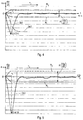
- Fig. 5 shows characteristics of a different aspiration cycle, in same representation as fig.4 and with the same scaling.
- the aspiration is significantly faster than in the example of fig.4 , i.e. the value of the extremum EXTR is significantly larger than that in fig.4 .
- the test criterion R(dp/dt) is, dependent from the larger analysis result, larger.
- fig.5 The aspiration cycle shown in fig.5 is acceptable too.
- Fig. 6 shows the characteristics of a further aspiration cycle. The scaling accords with that of figs.4 and 5 , although being shown enlarged.
- EXTR EXTR-dependent therefrom
- the time course of the first time derivative of the pressure p(t) leaves within ⁇ 2 the rated characteristic, i.e. the test criterion range, at the moment A, which course is attributed to a blockage of the pipette.
- the aspiration cycle as of fig. 6 is considered not acceptable.
- a method of aspirating a dose of a liquid by pipetting in an aspirating cycle, or of manufacturing a dose of a liquid including such aspirating method, and a pipetting apparatus are conceived, by which, automatically, an aspiration cycle is first analyzed and then checked on acceptance in dependency of the analyzing result.
- the number of entities governing the test criteria for the aspiration cycle is considerably reduced and unknown variations of such entities automatically considered.
Landscapes
- Engineering & Computer Science (AREA)
- Chemical & Material Sciences (AREA)
- Health & Medical Sciences (AREA)
- Life Sciences & Earth Sciences (AREA)
- Pathology (AREA)
- Analytical Chemistry (AREA)
- Biochemistry (AREA)
- General Health & Medical Sciences (AREA)
- General Physics & Mathematics (AREA)
- Immunology (AREA)
- Physics & Mathematics (AREA)
- Quality & Reliability (AREA)
- Human Computer Interaction (AREA)
- Clinical Laboratory Science (AREA)
- Chemical Kinetics & Catalysis (AREA)
- Mechanical Engineering (AREA)
- General Engineering & Computer Science (AREA)
- Hydrology & Water Resources (AREA)
- Sampling And Sample Adjustment (AREA)
- Feeding, Discharge, Calcimining, Fusing, And Gas-Generation Devices (AREA)
- Measuring Fluid Pressure (AREA)
- Automatic Analysis And Handling Materials Therefor (AREA)
- Devices For Use In Laboratory Experiments (AREA)
Abstract
Description
- The present invention is directed to a method of aspirating a dose of a liquid by pipetting and to a method for manufacturing a dose of a liquid including the addressed method of aspirating.
- For aspirating a dose of a liquid by pipetting, there is applied to the inner space of a pipette, once the tip of the pipette is in its aspiration position and should be immersed in the liquid to be aspired, a suctioning action or effect by means of a suctioning source.
- The suctioning action or effect is transmitted from the suctioning source to the tip of the pipette by a work fluid. The work fluid may consist of a liquid section or column or of a gaseous fluid section or of liquid sections with gaseous section in between and/or of a liquid section with a gaseous section at one or at both ends thereof. To avoid contact of the liquid being aspired with a liquid component of the work fluid it is common practice to select at least that section of the work fluid which contacts the liquid as aspired of a gaseous fluid. In spite of the fact that it is not excluded in the frame of the present invention that a liquid section of the work fluid is exploited in the pipette and down to its tip, the present invention particularly addresses a gaseous work fluid section in the pipette and down to its tip as well as in a pipette applicator arrangement of a pipetting apparatus. Once the suctioning action is initiated, conditioned by the suctioning action and dependent therefrom, parameters, i.e. physical entities at the pipetting apparatus as e.g. pressures, flows, weights etc. change due to additional material being taken up into the pipetting apparatus.
- It is widely known to check an aspiration cycle for correctness, i.e. acceptability, or non-correctness, i.e. non- acceptability, by establishing, generically spoken, criteria for parameters as addressed above which depend from the effect of suctioning action. Such criteria must be fulfilled by the respectively prevailing parameters during an aspiration cycle, which is considered acceptable.
- It is an object of the present invention to provide an improved method of and apparatus for aspirating.
- This is achieved by the method of aspirating a dose of a liquid by pipetting in an aspirating cycle, or of manufacturing a dose of a liquid including such aspirating method, comprising:
- a) Moving a pipette containing a work fluid in an aspiration position;
- b) Initiating at a point in time a suctioning action to the work fluid.
- When we speak throughout the present description and claims from a "point in time" the term "point" is not to be understood as a "point" according to geometric definitions but is to be understood as a short time interval just necessary to perform the respectively addressed technical action.
- The method further comprises:
- c) Analyzing at least one prevailing first parameter, being dependent from the effect or result of the suctioning action, within a first time span and subsequent the addressed initiating;
- In this analyzing step the at least one first prevailing parameter is evaluated. More than one first prevailing parameter may be evaluated.
- The method further comprises:
- d)Determining at least one test-criterion in dependency of at least one result of the analyzing;
The analyzing step may result in more than one result. One test-criterion may be dependent from a single analyzing result or from a combination of analyzing results. Also, more than one test criterion may be determined in dependency of a single analyzing result or in dependency of respective combinations of analyzing results.
Determining the at least one test-criterion may be done by calculation, e.g. if there exists a explicit mathematical function between the at least one analyzing result and the at least one test-criterion, e.g. proportionality, or by means of a look up table wherein analyzing results, possibly combinations thereof, are attributed to respective test-criteria.
The method further comprises: - e) Checking at least one second prevailing parameter, being dependent from the effect or result of the suctioning action, within a second time span subsequent to the addressed determining, upon whether the at least one prevailing second parameter does or does not fulfill the at least one test-criterion.
- When we speak of performing an action "within a time span" this means that such action is performed one time or more than one time within the time slot of the time span or is performed all along the time span.
- The method further comprises:
- f) Identifying the aspiration cycle as acceptable or as not acceptable in dependency of a result of the checking step.
- When we speak of "the effect of the suctioning action" we understand the aspiration effect which is caused by initiating and upholding the suctioning action. Such effect is dependent from the behavior of the suctioning action per se, once initiated, as well as from the effect of the suctioning action in the pipette.
- The inventors have thus found that:
- a) a multitude of conditions and of combinations thereof, which determine the effect or result of the suctioning action lead to the same behavior of at least one prevailing first parameter during a first time span subsequent initiating of the suctioning action.
- Conditions, which determine the effect or result of the suctioning action, are e.g. acceleration and deceleration of a suctioning pump in the different phases of the aspiration cycle, the amount of liquid to be aspirated, the starting pressure of the work fluid when suctioning is initiated, viscosity of the liquid to be aspired and from its density, the volume and shape of the inner space of the pipette, presence or non-presence of a pipette filter, pipette orifice shape and size, immersion depth of the pipette tip into the liquid to be aspired etc. conditions, which are possibly known. Besides of such conditions which may be known in advance, variations of such conditions, as by tolerances, are normally not known.
- b) initial behavior of at least one prevailing first parameter, largely independently from the conditions as addressed above and possibly combinations thereof, may be taken into account by at least one respectively selected test-criterion to be applied to at least one prevailing second prevailing parameter to decide about acceptability of the overall aspiration cycle.
Thus, one needs not to know the conditions which influence the suctioning effect with the target of setting test criteria. It suffices to know the behavior if the prevailing first parameter during a time span subsequent initialization of the suctioning effect. - This allows to significantly reduce the number of entities, the addressed conditions and combinations thereof, to be taken in account for checking the behavior of the system during the aspiration cycle. The amount of data e.g. in a lookup table associating analyzing results to test-criteria may be significantly reduced compared with a lookup table which must be installed if every influencing condition and combinations thereof are to be considered separately.
- If, as a simple example e.g. two sets or combinations of conditions have to be taken in account, two test-criteria have to be established which may be equal or different. If, according to the invention, the two sets of conditions are recognized as leading to the same behavior of an initially prevailing first parameter and this behavior may be taken as decisive for setting of the at least one test criterion, instead of two data-sets for the conditions, only one dataset for the first parameter behavior must be known in advance and respectively stored.
- In one variant of the method according to the invention the at least one prevailing first parameter at least comprises at least one of at least one pressure and of a flow dependent from at least one prevailing pressure in the work fluid, the work fluid being a liquid or at least comprising at least one a gaseous section.
- When we speak of "at least one pressure" this shall include e.g. a difference between two pressure values.
- In one variant of the method according to the invention the at least one prevailing first parameter is at least one of at least one pressure and of a flow of the work fluid, the work fluid being a liquid or at least comprising at least one gaseous section.
- In one variant of the method according to the invention the at least one prevailing second parameter at least comprises at least one of at least one pressure and of a flow dependent from at least one prevailing pressure in said work fluid, said work fluid being a liquid or at least comprising at least one gaseous section.
- In one variant of the method according to the invention the at least one prevailing second parameter is at least one of at least one pressure and of a flow of said work fluid, said work fluid being a liquid or at least comprising at least one gaseous section.
- In one variant of the method according to the invention the at least one prevailing first parameter at least comprises at least one of at least one pressure and of a flow at least dependent from at least one prevailing pressure in the work fluid, the work fluid being a liquid or at least comprising at least one gaseous section and the at least one prevailing second parameter at least comprises at least one of at least one pressure and of a flow at least dependent from at least one prevailing pressure in the work fluid.
- In one variant of the method according to the invention
- the at least one prevailing first parameter is at least one of at least one pressure and of a flow of the work fluid said work fluid being a liquid or at least comprising at least one gaseous section and
- the at least one prevailing second parameter is at least one of at least one pressure and of a flow of said work fluid.
- In one variant of the method according to the invention the analyzing comprises analyzing at least one first characteristic over time of the at least one prevailing first parameter.
- In one variant of the method according to the invention, the analyzing comprises analyzing at least one first characteristic over time of the at least one prevailing first parameter and wherein there prevails at least one of:
- said at least one prevailing first parameter at least comprising at least one of at least one pressure and of a flow at least dependent from at least one prevailing pressure in said work fluid, said work fluid being a liquid or at least comprising at least one gaseous section and of
- said at least one prevailing first parameter is at least one of at least one pressure and of a flow of said work fluid said work fluid being a liquid or at least comprising at least one gaseous section and of
- said at least one prevailing second parameter at least comprises at least one of at least one pressure and of a flow at least dependent from at least one prevailing pressure in said work fluid, said work fluid being a liquid or at least comprising at least one gaseous section and of
- said at least one prevailing second parameter is at least one of at least one pressure and of a flow of said work fluid said work fluid being a liquid or at least comprising at least one gaseous section.
- In one variant of the method according to the invention determining the at least one test-criterion comprises determining at least one rated second characteristic over time for said at least one prevailing second parameter.
- In one variant of the method according to the invention determining the at least one test-criterion comprises determining at least one rated second characteristic over time for the at least one prevailing second parameter and wherein there prevails at least one of:
- said at least one prevailing first parameter at least comprising at least one of at least one pressure and of a flow at least dependent from at least one prevailing pressure in said work fluid said work fluid being a liquid or at least comprising at least one gaseous section and of
- said at least one prevailing first parameter is at least one of at least one pressure and of a flow of said work fluid said work fluid being a liquid or at least comprising at least one gaseous section
- said at least one prevailing second parameter at least comprises at least one of at least one pressure and of a flow at least dependent from at least one prevailing pressure in said work fluid said work fluid being a liquid or at least comprising at least one gaseous section and of
- said at least one prevailing second parameter is at least one of at least one pressure and of a flow of said work fluid said work fluid being a liquid or at least comprising at least one gaseous section
- analyzing comprises determining at least one first characteristic over time of said at least one prevailing first parameter.
- In one variant of the method according to the invention, analyzing comprises analyzing a first time derivative of at least one of at least one pressure and of a flow dependent from said effect of said suctioning action.
- In one variant of the method according to the invention, said analyzing comprises analyzing a first time derivative of at least one of at least one pressure and of a flow dependent from said effect of said suctioning action and wherein there prevails at least one of:
- the work fluid is a liquid or at least comprising at least one gaseous section;
- the at least one prevailing first parameter is at least one of at least one pressure and of a flow of the work fluid, the work fluid being a liquid or at least comprising at least one gaseous section
- the at least one prevailing second parameter at least comprises at least one of at least one pressure and of a flow at least dependent from at least one prevailing pressure in the work fluid, the work fluid being a liquid or at least comprising at least one gaseous section
- the at least one prevailing second parameter is at least one of at least one pressure and of a flow of the work fluid , the work fluid being a liquid or at least comprising at least one gaseous section
- the analyzing comprises determining at least one first characteristic over time of the at least one prevailing first parameter,
- determining the at least one test-criterion comprises determining at least one rated second characteristic over time of the at least one prevailing second parameter.
- In one variant of the method according to the invention, the analyzing comprises analyzing a first time derivative of at least one of at least one pressure and of a flow dependent from said effect of said suctioning action, the at least one pressure or flow having the following prevailing time course:
- The first time derivative alters after the point in time towards an extremum value occurring at a moment and returns to some extent after said moment; determining is performed within the time span between the point in time and the moment, latter inclusive.
- In one variant of the method according to the invention said analyzing comprises analyzing a first time derivative of at least one of at least one pressure and of a flow dependent from said effect of said suctioning action, said at least one pressure or said flow having the following prevailing time course:
- The first time derivative alters after said point in time towards an extremum value occurring at a moment and returns to some extent after said moment;
said determining is performed within the time span between said point in time and said moment, latter inclusive and
wherein there prevails at least one of:- said at least one prevailing pressure or flow is respectively a pressure or a flow of said work fluid, said work fluid being a liquid or at least comprising at least one gaseous section and of
- said at least one prevailing second parameter at least comprises at least one of at least one pressure and of a flow at least dependent from at least one prevailing pressure in said work fluid, said work fluid being a liquid or at least comprising at least one gaseous section, and of
- said at least one prevailing second parameter is at least one of at least one pressure and of a flow of said work fluid, said work fluid being a liquid or at least comprising at least one gaseous section, and of
- said analyzing comprises analyzing a first time derivative of at least one of at least one pressure and of a flow dependent from said effect of said suctioning action and of
- determining said at least one test-criterion comprises determining at least one rated characteristic over time of said at least one prevailing second parameter
- said checking is performed at a time subsequent said moment.
- In one variant of the method according to the invention which may be combined with any variant already addressed unless in contradiction, the analyzing comprises evaluating at least one of
- at least one pressure value;
- at least one flow value
- at least one value of a first time derivative of a pressure course
- at least one value of a first time derivative of a flow course;
- at least one value of a second time derivative of a pressure course
- at least one value of a second time derivative of a flow course.
- In one variant of the method according to the invention which may be combined with any variant already addressed unless in contradiction, the at least one test-criterion comprises a range for at least one of
- a pressure value;
- a flow value;
- a first time-derivative of a pressure course
- a first time-derivative of a flow course
- a second time-derivative of a pressure course
- a second time-derivative of a flow course.
- In one variant of the method according to the invention which may be combined with any variant already addressed unless in contradiction, analyzing comprises evaluating at least one of
- at least one pressure value;
- at least one flow value;
- at least one value of a first time derivative of a pressure course
- at least one value of a first time derivative of a flow course
- at least one value of a second time derivative of a pressure course
- at least one value of a second time derivative of a flow course and
- a pressure value;
- a flow value;
- a first time-derivative of a pressure course
- a first time-derivative of a flow course
- a second time-derivative of a pressure course
- a second time-derivative of a flow course.
- In one variant of the method according to the invention which may be combined with any variant already addressed unless in contradiction said test criterion is a range and said checking is performed after said prevailing second parameter enters said range for a first time.
- We address the occurrence of an extremum "at a moment" rather than "at a point in time" because an extremum detection may be somehow unsharp, e.g. dependent of signal noise and time/ signal-value scaling.
- Addressing a generic point:
- It has to be considered that the method according to the invention might not be the sole procedure to check whether a prevailing aspiration cycle is acceptable or not. E.g. we have addressed that the pipette is moved in an aspiration position. Whether in this position the tip of the pipette is immersed in the liquid to be aspired or not, is instantaneously recognized e.g. from the prevailing pressure course in the pipette. The suctioning action will result in a prevailing pressure of the work fluid varying much less than when the tip would be immersed into a liquid. This may be detected immediately after initiating the aspiration cycle without exploiting the method according to the present invention. Thus, and as may be seen from this example, additional tests may be performed to check an aspiration cycle on acceptance.
- A test-criterion range as addressed above may be constant or may vary over time with respect to its width and/or its average value.
- All variants of the method according to the invention, which were addressed, may be combined if they are not in contradiction.
- The present invention is further directed to a pipetting apparatus comprising a pipette applicator arrangement for at least one pipette, a suction source in flow communication with an inner space of the pipette applicator arrangement, a sensor arrangement operationally connected to this inner space, the output of the sensor arrangement being operationally connected to an aspiration-cycle testing unit. The aspiration-cycle testing unit is configured to perform:
- Reception of a control signal representative for the pipette applicator arrangement having reached an aspiration position;
- Initiating, upon said control signal, applying to said inner space a suctioning action by said suction source at a point in time;
- Analyzing a signal dependent from an output signal of said sensor arrangement subsequent to said initiating;
- Determining at least one test-criterion in dependency of a result of said analyzing;
- Checking in a second time span, subsequent to said determining, whether a signal dependent from an output signal of said sensor arrangement does or does not fulfill said at least one test-criterion;
- Generating an indication whether said aspiration cycle is acceptable or not acceptable in dependency of a result of said checking.
- One embodiment of the apparatus according to the invention is configured to perform the method according to the invention or according to one or more than one of its variants.
- The present invention shall now be further exemplified with the help of figures. The figures show:
-
Fig. 1 : by means of a generic signal-flow/ functional-block diagram, the principle of the invention; -
Fig.2 : schematically and simplified by means of a signal-flow/ functional -block diagram, the method and apparatus according to the invention; -
Fig.3 : in a representation in analogy to that offig. 1 , a variant of the method and an embodiment of the apparatus according to the invention; -
Figs.4 to 6 : Characteristics of different aspiration cycles as exploited by and as resulting from the method and apparatus according to the example offig.3 . -
Fig. 1 most schematically shows, by means of a functional-block/ signal- flow diagram the principle of the present invention. - By means of a start signal, START suctioning action by a
pumping facility 100 upon thepipette arrangement 101 is initiated. Asensor arrangement 103 senses at least one prevailing first parameter Plst that is dependent from the effect in thepipette arrangement 101 of initiating and upholding the suctioning action. Thepumping facility 100, thepipette arrangement 101, thesensor arrangement 103 are represented in ahardware block 104 infig. 1 . Multiple conditions CON as of the suctioning facility, the liquid to be aspired, and the pipette influence the effect of initiating and upholding the suctioning action. The at least one prevailing first parameter Plst is analyzed in a analyzingstage 106. At least one analyze result RA determines in a determiningstage 108 at least one test-criterion TC for at least one second parameter P2nd sensed by thesensor arrangement 103. The at least one second parameter P2nd, prevailing after the test-criterion having been determined, is checked in achecking stage 110 whether it fulfills the at least one test-criterion TC. If the at least one second prevailing parameter P2nd fulfills the at least one test-criterion TC, the aspiration cycle is considered acceptable, if the at least one second prevailing parameter P2nd does not fulfil the at least one test-criterion TC, the aspiration cycle is not accepted. This is represented infig. 1 by a/na. -
Fig. 2 most schematically and simplified shows, by means of a signal flow/ functional block diagram a more specific example of the method according to the present invention and of a structure of the apparatus according to such example of the invention. - A
pipette 1 is mounted to apipette applicator arrangement 3. Thepipette applicator arrangement 3 may be tailored to receive one or more than one of thepipettes 1. Aninner space 2 of thepipette applicator arrangement 3 communicating with one or more than one of thepipette 1 and is operationally in flow communication with a suction facility orsource 5 shown inFig. 2 as a plunger pump. Thesuction source 5 is driven in a controlled manner by adrive 7, which e.g. generates a start signal ST when an aspiration cycle is initiated. - The
pipette applicator 3 is driven in a controlled manner by adrive 9, up and down as shown with a double-arrow Z and, customarily, additionally in the x/y plane. - According to the embodiment of
Fig. 2 theinner space 2 of the pipette-applicator arrangement 3, is filled with a gaseous work fluid section, especially with air. - A
pressure sensor arrangement 11 monitors the pressure p(t) in theinner space 2 of thepipette applicator 3 which is operative on thepipette 1. Instead of or additionally to a pressure sensor arrangement, a flow sensor arrangement may be provided (not shown infig.2 ). At theoutput 11o of the pressure sensor arrangement 11 a signal S(p(t)) is generated, e.g. a digital signal, representing the prevailing pressure p(t)in the gaseous section of the work fluid. Theoutput 11o of thepressure sensor arrangement 11 is first operationally fed to an analyzingstage 13. As shown schematically by a switchingunit 15, this is initiated e.g. by atimer stage 17, triggered by the start signal ST which is e.g. generated by thedrive 7 as the pipette tip arrived at the aspiration position. Within the time span τ1 the signal S(p(t)) and thus the time course of the pressure p(t), as a prevailing first parameter, prevailing during this time span τ1 in the work fluid in thepipette applicator arrangement 3, is analyzed. The result of the analysis in analyzingstage 13 is one or more than one characteristic values of the time course of the pressure p(t)as it prevails during τ1 in the work fluid. - Such characteristic value may be e.g.:
- One or more than one pressure values at respectively selected moments, possibly averaged over selected time spans,
- The pressure value of an extremum of the pressure, possibly averaged over a selected time span,
- The time or time slot when the pressure achieves an extremum,
- One or more than one values of a first time derivative of the time course of the pressure at respectively selected moments, possibly averaged over selected time spans,
- The extremum value of the first time derivative of the time course of the pressure
- The time or time slot when the first time derivative of the pressure achieves an extremum;
- One or more than one values of second time derivative of the time course of the pressure at respectively selected moments, possibly averaged over selected time spans
- The time sequence in which specific characteristic values occur etc.
- The time span τ1, initiated at the start of aspirating, has either a predetermined duration as shown in
fig.2 by selectingunit 18 or the end of τ1 is set by a selected behavior of the prevailing time course of the prevailing pressure p(t), e.g. by the occurrence of an extremum of the first time derivative of the prevailing time course of the prevailing pressure p(t)as of an example described later. Thus, the end of τ1 may be triggered by a result of the analyzing in analyzingstage 13, as shown infig.2 in dash line at E(τ1). At the end of the time span τ1 analyzing is terminated. - The result data of the analyzing process in analyzing
stage 13 are addressed infig 2 by Vn. They are fed to a determiningstage 19. In the determiningstage 19 one or more than one test criteria Cm are determined in dependency of the one or more than one result values Vn of the analyzing in the analyzingstage 13. The number m of test criteria determined by the determiningstage 19 is independent from the number n of result values of the analyzing step. - The test criteria may be e.g.:
- One or more than one range for pressure values in one or in more than one time spans of the aspiration cycle, whereby such ranges may be constant over a respective time span, may vary in width along a respective timespan and/or may vary with respect to the average value of the range.
- One or more than one ranges for the first time derivative and / or second time derivative of the time course of the pressure in one or in more than one time spans of the aspiration cycle, whereby such ranges may be constant over a respective time span, may vary in width along a respective timespan and/or may vary with respect to the average value of the range.
- From one single result value V1 of the analysis one test criterion C1 or more than one test criteria C1, C2... may be determined by the determining
stage 19. - On the other hand more than one result values V1, V2... of the analyzing in analyzing
stage 13 may be combined by the determiningstage 19 to determine a single test criterion, Cx(V1, V2...). - Determining the test criteria may be performed by calculation or by exploiting a lookup table wherein analysis results Vn and possibly combinations thereof and respective test criteria Cm are mutually collated.
- After the analyzing time span τ1 and after the test-criteria have been determined, the output signal S(p(t)) of the
sensor arrangement 11, as schematically shown by the switchingunit 15, is fed as input to a checkingstage 21, as a prevailing second parameter. The test criteria Cm as well are input to the checkingstage 21. - By the checking
stage 21 the prevailing time course of the prevailing pressure p(t) is checked whether it fulfills the test criteria Cm. - It becomes evident, that under a more generic consideration, the first parameter subjected to analysis and the second parameter subjected to checking as of
fig. 1 may be the same parameter. - Dependent on the fact which test criteria have been established by the determining
stage 21, the respective prevailing characteristic is monitored at the prevailing time course of the prevailing pressure, according to signal S(p(t)), in amonitoring stage 20. Thus if e.g. one of or the test criteria is directed to the first time derivative of the time course of the pressure, before performing the checking operation upon such test criterion, the prevailing first time derivative at the prevailing time course of the pressure is monitored atstage 20. - Whereas the checking operation may be initiated just after completion of the analyzing step, just after termination of τ1 and of completion of determining the one or the more than one test criterion at
stage 19, the moment or the time span in which checking is considered to be significant is to be separately considered. - As shown in
fig.2 the checking result RC is first passed to avalidation stage 23. Thevalidation stage 23 acts like a controlled switch. After or during applying a control signal Sc to thevalidation stage 23 the checking result RC is considered a valid qualification of the aspiration cycle with respect of its acceptability or non-acceptability. - The control signal Sc may be generated e.g.at a predetermined moment and/ or during a predetermined time span of the aspiration cycle, as e.g. controlled by the
timer stage 17, or e.g. when one of the test criteria is fulfilled, e.g. first time fulfilled, as will be exemplified. - Once the checking result RC is validated as a validity indication of the aspiration cycle, acceptability y/n is indicated at the
indication stage 25. - Please note that the first and/ or second parameters, which have been exemplified in the embodiment of
fig. 2 as pressure-values, may be realized by flow values. This is also valid for the subsequent considerations. - The method and apparatus of the invention are now further exemplified by a variant and an embodiment according to
fig.3 and characteristics according to thefigs 4 to 6 . -
Fig.3 is a representation in analogy with that offig.2 . The same reference numbers are used for those parts already addressed in context withfig.2 . - Upon start Signal ST, the
timer stage 17 switches, as schematized by switchingunit 15, the signal S(p(t) to the analyzingstage 13. The pressure p(t) drops as qualitatively shown infig.4 by dash doted characteristic (a) . - The analyzing
stage 13 comprises a differentiatingstage 131 in which the first time derivative of S(p(t)) is calculated. This first time derivative, resulting from the dropping pressure as of (a) is shown infig.4 by characteristic (b). - Please note the scaling in
figs.4 to 6 is in arbitrary units. - The analyzing
stage 13 further comprises anextremum detection stage 132, which detects occurrence of the extremum EXTR of the first time derivative. Detection of the extremum EXTR controls, as shown by control signal E(τ1) termination of the time span τ1. Once the extremum EXTR is detected, the extremum value of the first time derivative is determined as the analyzing result V1. At this time the relevant analyzing result V1 i.e. the value of EXTR, is fed to the determiningstage 191 as schematically shown by control signal C132 and switchingunit 133. Further, as schematically shown by switchingunit 15, the signal S(pt) is now disconnected from the input to analyzingstage 13. - In dependency of V1, the determining
stage 191 determines, as a test criterion C1, a range R (dp/dt) for the values of the first time derivative of the time course of the pressure. This range is shown infig.4 by the upper limit Ru and the lower limit R1 characteristics. - Whereas termination of the analyzing time span τ1 is controlled in this embodiment or variant, by detecting the extremum EXTR of the first time derivative of the time course of the pressure, it is only after that the test criterion C1 has been determined by determining stage 19i,that the signal S(p(t)) is fed, as schematically represented via
switch unit 15 and aswitch unit 134 to themonitoring stage 20 whereat, in this embodiment, the first time derivative of the signal S(p(t)), as the second parameter, is monitored. - The test criterion C1, determined in dependency from the analyzing result V1, e.g. by calculation or by making use of a look up table, is fed to a
comparator stage 136, according to the checkingstage 21 offig.2 , where it is compared with the prevailing first time derivative of the prevailing time course of the prevailing pressure.
The comparison result RC is represented infig. 4 by an output n and an output y of thecomparator stage 136. If the prevailing first time derivative of the prevailing time course of the pressure is within the test range R (dp/dt) than a signal is generated at the output y otherwise at output n. - According to the
validation stage 23 offig.3 , when the output y is activated for the first time, i.e. when the prevailing time derivative enters the range R(dp/dt)for the first time, the signal Sc triggers aunit 138, operating as a monostable unit, and from this moment and for the subsequent time span τ2 shown infig.4 , the output of thecomparator stage 136 is considered as validated for indicating at theindicator stage 25, whether -y- the actual aspiration cycle is valid or -n- invalid. As may be seen inFig.4 , the time course of the first time derivative of the pressure p(t) remains within the range R(dp/dt) during the time span τ2 and is therefore considered as acceptable. -
Fig. 5 shows characteristics of a different aspiration cycle, in same representation asfig.4 and with the same scaling. The aspiration is significantly faster than in the example offig.4 , i.e. the value of the extremum EXTR is significantly larger than that infig.4 . The test criterion R(dp/dt) is, dependent from the larger analysis result, larger. - The aspiration cycle shown in
fig.5 is acceptable too.
Fig. 6 shows the characteristics of a further aspiration cycle. The scaling accords with that offigs.4 and 5 , although being shown enlarged. - The value of EXTR is lower than that in
fig.4 and thus the range R(dp/dt) dependent therefrom is smaller. As may be seen, the time course of the first time derivative of the pressure p(t) leaves within τ2 the rated characteristic, i.e. the test criterion range, at the moment A, which course is attributed to a blockage of the pipette. The aspiration cycle as offig. 6 is considered not acceptable. - Thus and according to the present invention, a method of aspirating a dose of a liquid by pipetting in an aspirating cycle, or of manufacturing a dose of a liquid including such aspirating method, and a pipetting apparatus are conceived, by which, automatically, an aspiration cycle is first analyzed and then checked on acceptance in dependency of the analyzing result. The number of entities governing the test criteria for the aspiration cycle is considerably reduced and unknown variations of such entities automatically considered.
Claims (21)
- A method of aspirating a dose of a liquid by pipetting in an aspirating cycle, or of manufacturing a dose of a liquid including such aspirating method, the method comprising:a) moving a pipette containing a work fluid in an aspiration position;b) initiating at a point in time a suctioning action to said work fluid;c) analyzing at least one prevailing first parameter, being dependent from an effect of said suctioning action, within a first time span subsequent said initiating;d) determining at least one test-criterion in dependency of at least one result of said analyzing;e) checking at least one second prevailing parameter, being dependent from an effect of said suctioning action, within a second time span subsequent to said determining, upon whether said at least one prevailing second parameter does or does not fulfill said at least one test-criterion;f) identifying said aspirating cycle as acceptable or as not acceptable in dependency of a result of said checking.
- The method of claim 1 said at least one prevailing first parameter at least comprising at least one of at least one pressure and of a flow dependent from at least one prevailing pressure in said work fluid, said work fluid being a liquid or at least comprising at least one gaseous section.
- The method of claim 1 said at least one prevailing first parameter is at least one of at least one pressure and of a flow of said work fluid, said work fluid being a liquid or at least comprising at least one gaseous section.
- The method of claim 1 wherein said at least one prevailing second parameter at least comprises at least one of at least one pressure and of a flow dependent from at least one prevailing pressure in said work fluid, said work fluid being a liquid or at least comprising at least one gaseous section.
- The method of claim 1 said at least one prevailing second parameter is at least one of at least one pressure and of a flow of said work fluid, said work fluid being a liquid or at least comprising at least one gaseous section.
- The method of claim 1, wherein said at least one prevailing first parameter at least comprising at least one of at least one pressure and of a flow at least dependent from at least one prevailing pressure in said work fluid said work fluid being a liquid or at least comprising at least one gaseous section and said at least one prevailing second parameter at least comprises at least one of at least one pressure and of a flow at least dependent from at least one prevailing pressure in said work fluid.
- The method of claim 1, wherein:• said at least one prevailing first parameter is at least one of at least one pressure and of a flow of said work fluid, said work fluid being a liquid or at least comprising at least one gaseous section and• said at least one prevailing second parameter is at least one of at least one pressure and of a flow of said work fluid.
- The method of claim 1, wherein• said analyzing comprises analyzing at least one first characteristic over time of said at least one prevailing first parameter.
- The method of claim 1, said analyzing comprising analyzing at least one first characteristic over time of said at least one prevailing first parameter and wherein there prevails at least one of:• said at least one prevailing first parameter at least comprising at least one of at least one pressure and of a flow dependent from at least one prevailing pressure in said work fluid said work fluid being a liquid or at least comprising at least one gaseous section and of• said at least one prevailing first parameter is at least one of at least one pressure and of a flow of said work fluid said work fluid being a liquid or at least comprising at least one gaseous section and of• said at least one prevailing second parameter at least comprises at least one of at least one pressure and of a flow dependent from at least one prevailing pressure in said work fluid, said work fluid being a liquid or at least comprising at least one gaseous section and of• said at least one prevailing second parameter is at least one of at least one pressure and of a flow of said work fluid said work fluid being a liquid or at least comprising at least one gaseous section.
- The method of claim 1 wherein determining said at least one test-criterion comprises determining at least one rated second characteristic over time for said at least one prevailing second parameter.
- The method of claim 1 wherein determining said at least one test-criterion comprises determining at least one rated second characteristic over time for said at least one prevailing second parameter and wherein there prevails at least one of:• said at least one prevailing first parameter at least comprising at least one of at least one pressure and of a flow at least dependent from at least one prevailing pressure in said work fluid said work fluid being a liquid or at least comprising at least one gaseous section and of• said at least one prevailing first parameter is at least one of at least one pressure and of a flow of said work fluid said work fluid being a liquid or at least comprising at least one gaseous section• said at least one prevailing second parameter at least comprises at least one of at least one pressure and of a flow dependent from at least one prevailing pressure in said work fluid said work fluid being a liquid or at least comprising at least one gaseous section and of• said at least one prevailing second parameter is at least one of at least one pressure and of a flow of said work fluid said work fluid being a liquid or at least comprising at least one gaseous section• said analyzing comprises determining at least one first characteristic over time of said at least one prevailing first parameter.
- The method of claim 1, wherein said analyzing comprises analyzing a first time derivative of at least one of at least one pressure and of a flow dependent from effect of said suctioning action.
- The method of claim 1, wherein said analyzing comprises analyzing a first time derivative of at least one of at least one pressure and of a flow dependent from said effect of said suctioning action and wherein there prevails at least one of:• said work fluid being a liquid or at least comprising at least one gaseous section;• said at least one prevailing first parameter is at least one of at least one pressure and of a flow of said work fluid, said work fluid being a liquid or at least comprising at least one gaseous section• said at least one prevailing second parameter at least comprises at least one of at least one pressure and of a flow dependent from at least one prevailing pressure in said work fluid, said work fluid being a liquid or at least comprising at least one gaseous section• said at least one prevailing second parameter is at least one of at least one pressure and of a flow of said work fluid said work fluid being a liquid or at least comprising at least one gaseous section• said analyzing comprises determining at least one first characteristic over time of said at least one prevailing first parameter,• determining said at least one test-criterion comprises determining at least one rated second characteristic over time of said at least one prevailing second parameter.
- The method of claim 1 wherein said analyzing comprises analyzing a first time derivative of at least one of at least one pressure and of a flow dependent from said effect of said suctioning action, said at least one pressure or said flow having the following prevailing time course:• The first time derivative alters after said point in time towards an extremum value occurring at a moment and returns to some extent after said moment;• said determining is performed within the time span between said point in time and said moment, latter inclusive.
- The method of claim 1 wherein said analyzing comprises analyzing a first time derivative of at least one of at least one pressure and of a flow dependent from said effect of said suctioning action, said at least one pressure or said flow having the following prevailing time course:• The first time derivative alters after said point in time towards an extremum value occurring at a moment and returns to some extent after said moment;wherein there prevails at least one of:
said determining is performed within the time span between said point in time and said moment, latter inclusive and• said at least one prevailing pressure or flow is respectively at least one pressure or a flow of said work fluid, said work fluid being a liquid or at least comprising at least one gaseous section and of• said at least one prevailing second parameter at least comprises at least one of at least one pressure and of a flow at least dependent from at least one prevailing pressure in said work fluid, said work fluid being a liquid or at least comprising at least one gaseous section, and of• said at least one prevailing second parameter is at least one of at least one pressure and of a flow of said work fluid, said work fluid being a liquid or at least comprising at least one gaseous section, and of• said analyzing comprises analyzing a first time derivative of at least one of at least one pressure and of a flow dependent from said effect of said suctioning action, and of• determining said at least one test-criterion comprises determining at least one rated characteristic over time of said at least one prevailing second parameter• said checking is performed at a time subsequent said moment. - The method of one of claims 1 to 15 wherein said analyzing comprises evaluating at least one of• at least one pressure value;• at least one flow value;• at least one value of a first time derivative of a pressure course;• at least one value of a first time derivative of a flow course;• at least one value of a second time derivative of a pressure course;• at least one value of a second time derivative of a flow course.
- The method of one of claims 1 to 15, wherein said at least one test-criterion comprises a range for at least one of• a pressure value;• a flow value;• a first time-derivative of a pressure course;• a first time-derivative of a flow course;• a second time-derivative of a pressure course;• a second time-derivative of a flow course.
- The method of one of claims 1 to 15, wherein said analyzing comprises evaluating at least one of• at least one pressure value;• at least one flow value;• at least one value of a first time derivative of a pressure course;• at least one value of a first time derivative of a flow course;• at least one value of a second time derivative of a pressure course;• at least one value of a second time derivative of a flow course andwherein said at least one test-criterion comprises a range for at least one of• a pressure value;• a flow value;• a first time-derivative of a pressure course;• a first time-derivative of a flow course;• a second time-derivative of a pressure course;• a second time-derivative of a flow course.
- The method of one of claims 1 to 15 wherein said criterion is a range and said checking is performed after said prevailing second parameter enters said range for a first time.
- A pipetting apparatus comprising a pipette applicator arrangement for at least one pipette, a suction source in flow communication with an inner space of said pipette applicator arrangement, a sensor arrangement operationally connected to said inner space, the output of said sensor arrangement being operationally connected to an aspiration-cycle testing unit configured to perform• reception of a control signal representative for the pipette applicator arrangement having reached an aspiration position;• initiating applying to said inner space a suctioning action by said suction source at a point in time;• analyzing a signal dependent from an output signal of said sensor arrangement subsequent to said initiating;• determining at least one test-criterion in dependency of a result of said analyzing;• checking in a second time span, subsequent to said determining, whether a signal dependent from an output signal of said sensor arrangement does or does not fulfill said at least one test-criterion;• generating an indication whether said aspiration cycle is acceptable or not acceptable in dependency of a result of said checking.
- A pipetting apparatus configured to perform the method according to one of claims 1 to 19.
Applications Claiming Priority (1)
| Application Number | Priority Date | Filing Date | Title |
|---|---|---|---|
| US15/420,693 US10859592B2 (en) | 2017-01-31 | 2017-01-31 | Method of aspirating by pipetting and pipetting apparatus |
Publications (2)
| Publication Number | Publication Date |
|---|---|
| EP3355067A1 true EP3355067A1 (en) | 2018-08-01 |
| EP3355067B1 EP3355067B1 (en) | 2022-09-28 |
Family
ID=60569758
Family Applications (1)
| Application Number | Title | Priority Date | Filing Date |
|---|---|---|---|
| EP17205020.5A Active EP3355067B1 (en) | 2017-01-31 | 2017-12-01 | Method of aspirating by pipetting and pipetting apparatus |
Country Status (4)
| Country | Link |
|---|---|
| US (1) | US10859592B2 (en) |
| EP (1) | EP3355067B1 (en) |
| JP (2) | JP2018134631A (en) |
| CN (2) | CN113958493B (en) |
Families Citing this family (1)
| Publication number | Priority date | Publication date | Assignee | Title |
|---|---|---|---|---|
| US12496577B2 (en) | 2022-05-11 | 2025-12-16 | Revvity Health Sciences, Inc. | Pipetting apparatus and methods |
Citations (7)
| Publication number | Priority date | Publication date | Assignee | Title |
|---|---|---|---|---|
| US5537880A (en) * | 1995-06-07 | 1996-07-23 | Abbott Laboratories | Automatic pipetting apparatus with leak detection and method of detecting a leak |
| WO2001088549A1 (en) * | 2000-05-15 | 2001-11-22 | Dade Behring Inc. | Method for verifying the integrity of a fluid transfer |
| US20040089051A1 (en) * | 2001-03-09 | 2004-05-13 | Camenisch Johann L. | Method and device for evaluating a liquid dosing process |
| EP1992952A2 (en) * | 2007-05-15 | 2008-11-19 | Hitachi High-Technologies Corporation | Liquid dispensing apparatus |
| EP2302397A1 (en) * | 2009-09-25 | 2011-03-30 | bioMérieux S.A. | Method, computer program, and apparatus for detecting pipetting errors |
| WO2013181305A1 (en) * | 2012-05-31 | 2013-12-05 | Siemens Healthcare Diagnostics Inc. | Real time detection of aspiration short shots using pressure signal |
| WO2014055590A1 (en) * | 2012-10-04 | 2014-04-10 | Siemens Healthcare Diagnostics Inc. | Methods and apparatus for measuring aspiration pressure at low aspiration volumes |
Family Cites Families (24)
| Publication number | Priority date | Publication date | Assignee | Title |
|---|---|---|---|---|
| US3766747A (en) * | 1972-01-06 | 1973-10-23 | Lennox Ind Inc | Liquid sensor for reciprocating refrigerant compressor |
| JPS4912401A (en) * | 1972-05-17 | 1974-02-02 | ||
| FR2633719B1 (en) * | 1988-06-30 | 1991-04-19 | Inst Francais Du Petrole | MEASURING METHOD AND DEVICE FOR DETERMINING A PUMPING CHARACTERISTIC OR A PARAMETER OF A FLUID |
| DE4237904C2 (en) * | 1992-11-10 | 1995-10-05 | Tuchenhagen Otto Gmbh | Method and device for regulating the flow of a flowable substance to be metered |
| JP2711215B2 (en) | 1993-11-29 | 1998-02-10 | アロカ株式会社 | Automatic dispensing device |
| JPH0915248A (en) * | 1995-06-29 | 1997-01-17 | Nissho Corp | Dispensing operation determination device and method |
| KR100633873B1 (en) * | 1997-05-26 | 2006-10-13 | 마틴 레흐만 | Leak test method and device |
| DE10234630A1 (en) * | 2002-07-29 | 2004-04-08 | Wilo Ag | Method for determining the flow rate of a fluid through a pump |
| CN1311913C (en) * | 2004-10-28 | 2007-04-25 | 博奥生物有限公司 | A micro-liquid injection system |
| ITRM20050373A1 (en) * | 2005-07-13 | 2007-01-14 | Seko Bono Exacta S P A | PILOT DEVICE FOR A PUMP OPERATING ELECTROMAGNET, AND RELATED DOSING ELECTROMAGNETIC PUMP. |
| EP1745851B1 (en) * | 2005-07-22 | 2015-02-25 | Tecan Trading AG | Process, device and computerprogramm product for the classification of a liquid |
| US8715573B2 (en) * | 2006-10-13 | 2014-05-06 | Accuri Cytometers, Inc. | Fluidic system for a flow cytometer with temporal processing |
| AT9241U3 (en) * | 2007-02-05 | 2007-12-15 | Avl List Gmbh | METHOD AND DEVICE FOR CONTINUOUS MEASUREMENT OF DYNAMIC FLUID CONSUMPTION |
| EP2009449A1 (en) * | 2007-06-06 | 2008-12-31 | Hamilton Bonaduz AG | Method of controlling a pipetting process |
| EP2031403B1 (en) * | 2007-08-27 | 2016-02-17 | Roche Diagnostics GmbH | Method for monitoring a fluid transfer process |
| US7926325B2 (en) | 2008-04-23 | 2011-04-19 | Siemens Healthcare Diagnostics Inc. | Differentiating between abnormal sample viscosities and pipette clogging during aspiration |
| KR101398705B1 (en) * | 2010-02-23 | 2014-06-19 | 아르테미스 인텔리전트 파워 리미티드 | Fluid-working machine and method of operating a fluid-working machine |
| JP5624825B2 (en) * | 2010-07-29 | 2014-11-12 | 株式会社日立ハイテクノロジーズ | Liquid chromatograph pump and liquid chromatograph |
| FR2977317B1 (en) * | 2011-06-28 | 2013-08-02 | Gilson Sas | METHOD FOR DETECTING ANOMALIES WHEN FILLING A LIQUID ASSAY DEVICE AND LIQUID ASSAY DEVICE |
| DE102012206041A1 (en) * | 2012-04-13 | 2013-10-17 | Zf Friedrichshafen Ag | Apparatus and method for driving an auxiliary pump of a transmission |
| EP2818873A1 (en) * | 2013-06-24 | 2014-12-31 | Seyonic SA | Method of controlling pipetting operations |
| GB2521148B (en) * | 2013-12-10 | 2016-06-08 | Kind Consumer Ltd | Airflow testing apparatus |
| CN103852437B (en) * | 2014-03-22 | 2016-05-04 | 中国科学院合肥物质科学研究院 | A kind of mid-infrared light spectral measurement system and method for greenhouse gas emission flux |
| DE102014222390A1 (en) * | 2014-11-03 | 2016-05-04 | Continental Automotive Gmbh | Method for creating a characteristic field of a fluid pump, use of a limited valve, use of a stepped valve and control unit for a fluid delivery system |
-
2017
- 2017-01-31 US US15/420,693 patent/US10859592B2/en active Active
- 2017-12-01 EP EP17205020.5A patent/EP3355067B1/en active Active
-
2018
- 2018-01-30 JP JP2018013631A patent/JP2018134631A/en active Pending
- 2018-01-31 CN CN202111216012.4A patent/CN113958493B/en active Active
- 2018-01-31 CN CN201810094460.3A patent/CN108374783B/en active Active
-
2022
- 2022-12-21 JP JP2022204142A patent/JP7536070B2/en active Active
Patent Citations (7)
| Publication number | Priority date | Publication date | Assignee | Title |
|---|---|---|---|---|
| US5537880A (en) * | 1995-06-07 | 1996-07-23 | Abbott Laboratories | Automatic pipetting apparatus with leak detection and method of detecting a leak |
| WO2001088549A1 (en) * | 2000-05-15 | 2001-11-22 | Dade Behring Inc. | Method for verifying the integrity of a fluid transfer |
| US20040089051A1 (en) * | 2001-03-09 | 2004-05-13 | Camenisch Johann L. | Method and device for evaluating a liquid dosing process |
| EP1992952A2 (en) * | 2007-05-15 | 2008-11-19 | Hitachi High-Technologies Corporation | Liquid dispensing apparatus |
| EP2302397A1 (en) * | 2009-09-25 | 2011-03-30 | bioMérieux S.A. | Method, computer program, and apparatus for detecting pipetting errors |
| WO2013181305A1 (en) * | 2012-05-31 | 2013-12-05 | Siemens Healthcare Diagnostics Inc. | Real time detection of aspiration short shots using pressure signal |
| WO2014055590A1 (en) * | 2012-10-04 | 2014-04-10 | Siemens Healthcare Diagnostics Inc. | Methods and apparatus for measuring aspiration pressure at low aspiration volumes |
Also Published As
| Publication number | Publication date |
|---|---|
| CN108374783B (en) | 2021-10-29 |
| JP2018134631A (en) | 2018-08-30 |
| CN113958493A (en) | 2022-01-21 |
| EP3355067B1 (en) | 2022-09-28 |
| US10859592B2 (en) | 2020-12-08 |
| CN108374783A (en) | 2018-08-07 |
| JP2023029407A (en) | 2023-03-03 |
| US20180214862A1 (en) | 2018-08-02 |
| JP7536070B2 (en) | 2024-08-19 |
| CN113958493B (en) | 2024-08-27 |
Similar Documents
| Publication | Publication Date | Title |
|---|---|---|
| EP3594693A1 (en) | Device for detecting leading end of pipette tip, and program for detecting leading end of pipette tip | |
| EP2009449A1 (en) | Method of controlling a pipetting process | |
| AU763656B2 (en) | Biological sampling method | |
| EP2662137A1 (en) | Dispensing assembly | |
| EP0866970A1 (en) | Fluid handler and method of handling a fluid | |
| US20090266149A1 (en) | Differentiating Between Abnormal Sample Viscosities and Pipette Clogging During Aspiration | |
| JP7372245B2 (en) | Device and method for automatic liquid transfer optimized dispensing | |
| US12326459B2 (en) | Automatic analyzer | |
| US11781899B2 (en) | Method for the verification of pipettes | |
| US10139260B2 (en) | Method for controlling pipetting operations | |
| JPH0121911B2 (en) | ||
| EP3355067B1 (en) | Method of aspirating by pipetting and pipetting apparatus | |
| JP2021508827A5 (en) | ||
| EP2485030A1 (en) | Device for detetcting gas leaks, particualrly for joints of pipes and the like | |
| EP2480898B1 (en) | Method, computer program, and apparatus for detecting pipetting errors | |
| CN113466481A (en) | Filter state detection system and detection method | |
| EP1812163B1 (en) | Method for checking the condition of a sample when metering liquid | |
| JPH02196963A (en) | Detection of short sample of automatic dispenser | |
| JP2012154917A (en) | Abnormality determination method of solid phase extraction and solid phase extraction device | |
| JP2005201833A (en) | Dispensing device | |
| CN119076075A (en) | Liquid aspiration with volume compensation | |
| JP2018134631A5 (en) | ||
| CN118111529A (en) | Suction detection method and device | |
| CN119968564A (en) | Dispensing device and method for confirming status of probe | |
| HK1106827B (en) | Method for checking the condition of a sample when metering liquid |
Legal Events
| Date | Code | Title | Description |
|---|---|---|---|
| PUAI | Public reference made under article 153(3) epc to a published international application that has entered the european phase |
Free format text: ORIGINAL CODE: 0009012 |
|
| STAA | Information on the status of an ep patent application or granted ep patent |
Free format text: STATUS: THE APPLICATION HAS BEEN PUBLISHED |
|
| AK | Designated contracting states |
Kind code of ref document: A1 Designated state(s): AL AT BE BG CH CY CZ DE DK EE ES FI FR GB GR HR HU IE IS IT LI LT LU LV MC MK MT NL NO PL PT RO RS SE SI SK SM TR |
|
| AX | Request for extension of the european patent |
Extension state: BA ME |
|
| STAA | Information on the status of an ep patent application or granted ep patent |
Free format text: STATUS: REQUEST FOR EXAMINATION WAS MADE |
|
| 17P | Request for examination filed |
Effective date: 20190129 |
|
| RBV | Designated contracting states (corrected) |
Designated state(s): AL AT BE BG CH CY CZ DE DK EE ES FI FR GB GR HR HU IE IS IT LI LT LU LV MC MK MT NL NO PL PT RO RS SE SI SK SM TR |
|
| STAA | Information on the status of an ep patent application or granted ep patent |
Free format text: STATUS: EXAMINATION IS IN PROGRESS |
|
| 17Q | First examination report despatched |
Effective date: 20210728 |
|
| INTG | Intention to grant announced |
Effective date: 20220506 |
|
| GRAS | Grant fee paid |
Free format text: ORIGINAL CODE: EPIDOSNIGR3 |
|
| STAA | Information on the status of an ep patent application or granted ep patent |
Free format text: STATUS: GRANT OF PATENT IS INTENDED |
|
| GRAA | (expected) grant |
Free format text: ORIGINAL CODE: 0009210 |
|
| STAA | Information on the status of an ep patent application or granted ep patent |
Free format text: STATUS: THE PATENT HAS BEEN GRANTED |
|
| AK | Designated contracting states |
Kind code of ref document: B1 Designated state(s): AL AT BE BG CH CY CZ DE DK EE ES FI FR GB GR HR HU IE IS IT LI LT LU LV MC MK MT NL NO PL PT RO RS SE SI SK SM TR |
|
| REG | Reference to a national code |
Ref country code: GB Ref legal event code: FG4D |
|
| REG | Reference to a national code |
Ref country code: CH Ref legal event code: EP |
|
| REG | Reference to a national code |
Ref country code: AT Ref legal event code: REF Ref document number: 1521562 Country of ref document: AT Kind code of ref document: T Effective date: 20221015 |
|
| REG | Reference to a national code |
Ref country code: DE Ref legal event code: R096 Ref document number: 602017062105 Country of ref document: DE |
|
| REG | Reference to a national code |
Ref country code: IE Ref legal event code: FG4D |
|
| REG | Reference to a national code |
Ref country code: LT Ref legal event code: MG9D |
|
| PG25 | Lapsed in a contracting state [announced via postgrant information from national office to epo] |
Ref country code: SE Free format text: LAPSE BECAUSE OF FAILURE TO SUBMIT A TRANSLATION OF THE DESCRIPTION OR TO PAY THE FEE WITHIN THE PRESCRIBED TIME-LIMIT Effective date: 20220928 Ref country code: RS Free format text: LAPSE BECAUSE OF FAILURE TO SUBMIT A TRANSLATION OF THE DESCRIPTION OR TO PAY THE FEE WITHIN THE PRESCRIBED TIME-LIMIT Effective date: 20220928 Ref country code: NO Free format text: LAPSE BECAUSE OF FAILURE TO SUBMIT A TRANSLATION OF THE DESCRIPTION OR TO PAY THE FEE WITHIN THE PRESCRIBED TIME-LIMIT Effective date: 20221228 Ref country code: LV Free format text: LAPSE BECAUSE OF FAILURE TO SUBMIT A TRANSLATION OF THE DESCRIPTION OR TO PAY THE FEE WITHIN THE PRESCRIBED TIME-LIMIT Effective date: 20220928 Ref country code: LT Free format text: LAPSE BECAUSE OF FAILURE TO SUBMIT A TRANSLATION OF THE DESCRIPTION OR TO PAY THE FEE WITHIN THE PRESCRIBED TIME-LIMIT Effective date: 20220928 Ref country code: FI Free format text: LAPSE BECAUSE OF FAILURE TO SUBMIT A TRANSLATION OF THE DESCRIPTION OR TO PAY THE FEE WITHIN THE PRESCRIBED TIME-LIMIT Effective date: 20220928 |
|
| REG | Reference to a national code |
Ref country code: NL Ref legal event code: MP Effective date: 20220928 |
|
| REG | Reference to a national code |
Ref country code: AT Ref legal event code: MK05 Ref document number: 1521562 Country of ref document: AT Kind code of ref document: T Effective date: 20220928 |
|
| PG25 | Lapsed in a contracting state [announced via postgrant information from national office to epo] |
Ref country code: HR Free format text: LAPSE BECAUSE OF FAILURE TO SUBMIT A TRANSLATION OF THE DESCRIPTION OR TO PAY THE FEE WITHIN THE PRESCRIBED TIME-LIMIT Effective date: 20220928 Ref country code: GR Free format text: LAPSE BECAUSE OF FAILURE TO SUBMIT A TRANSLATION OF THE DESCRIPTION OR TO PAY THE FEE WITHIN THE PRESCRIBED TIME-LIMIT Effective date: 20221229 |
|
| PG25 | Lapsed in a contracting state [announced via postgrant information from national office to epo] |
Ref country code: SM Free format text: LAPSE BECAUSE OF FAILURE TO SUBMIT A TRANSLATION OF THE DESCRIPTION OR TO PAY THE FEE WITHIN THE PRESCRIBED TIME-LIMIT Effective date: 20220928 Ref country code: RO Free format text: LAPSE BECAUSE OF FAILURE TO SUBMIT A TRANSLATION OF THE DESCRIPTION OR TO PAY THE FEE WITHIN THE PRESCRIBED TIME-LIMIT Effective date: 20220928 Ref country code: PT Free format text: LAPSE BECAUSE OF FAILURE TO SUBMIT A TRANSLATION OF THE DESCRIPTION OR TO PAY THE FEE WITHIN THE PRESCRIBED TIME-LIMIT Effective date: 20230130 Ref country code: ES Free format text: LAPSE BECAUSE OF FAILURE TO SUBMIT A TRANSLATION OF THE DESCRIPTION OR TO PAY THE FEE WITHIN THE PRESCRIBED TIME-LIMIT Effective date: 20220928 Ref country code: CZ Free format text: LAPSE BECAUSE OF FAILURE TO SUBMIT A TRANSLATION OF THE DESCRIPTION OR TO PAY THE FEE WITHIN THE PRESCRIBED TIME-LIMIT Effective date: 20220928 Ref country code: AT Free format text: LAPSE BECAUSE OF FAILURE TO SUBMIT A TRANSLATION OF THE DESCRIPTION OR TO PAY THE FEE WITHIN THE PRESCRIBED TIME-LIMIT Effective date: 20220928 |
|
| PG25 | Lapsed in a contracting state [announced via postgrant information from national office to epo] |
Ref country code: SK Free format text: LAPSE BECAUSE OF FAILURE TO SUBMIT A TRANSLATION OF THE DESCRIPTION OR TO PAY THE FEE WITHIN THE PRESCRIBED TIME-LIMIT Effective date: 20220928 Ref country code: PL Free format text: LAPSE BECAUSE OF FAILURE TO SUBMIT A TRANSLATION OF THE DESCRIPTION OR TO PAY THE FEE WITHIN THE PRESCRIBED TIME-LIMIT Effective date: 20220928 Ref country code: IS Free format text: LAPSE BECAUSE OF FAILURE TO SUBMIT A TRANSLATION OF THE DESCRIPTION OR TO PAY THE FEE WITHIN THE PRESCRIBED TIME-LIMIT Effective date: 20230128 Ref country code: EE Free format text: LAPSE BECAUSE OF FAILURE TO SUBMIT A TRANSLATION OF THE DESCRIPTION OR TO PAY THE FEE WITHIN THE PRESCRIBED TIME-LIMIT Effective date: 20220928 |
|
| P01 | Opt-out of the competence of the unified patent court (upc) registered |
Effective date: 20230522 |
|
| REG | Reference to a national code |
Ref country code: DE Ref legal event code: R097 Ref document number: 602017062105 Country of ref document: DE |
|
| PG25 | Lapsed in a contracting state [announced via postgrant information from national office to epo] |
Ref country code: NL Free format text: LAPSE BECAUSE OF FAILURE TO SUBMIT A TRANSLATION OF THE DESCRIPTION OR TO PAY THE FEE WITHIN THE PRESCRIBED TIME-LIMIT Effective date: 20220928 Ref country code: AL Free format text: LAPSE BECAUSE OF FAILURE TO SUBMIT A TRANSLATION OF THE DESCRIPTION OR TO PAY THE FEE WITHIN THE PRESCRIBED TIME-LIMIT Effective date: 20220928 |
|
| PG25 | Lapsed in a contracting state [announced via postgrant information from national office to epo] |
Ref country code: DK Free format text: LAPSE BECAUSE OF FAILURE TO SUBMIT A TRANSLATION OF THE DESCRIPTION OR TO PAY THE FEE WITHIN THE PRESCRIBED TIME-LIMIT Effective date: 20220928 |
|
| PLBE | No opposition filed within time limit |
Free format text: ORIGINAL CODE: 0009261 |
|
| STAA | Information on the status of an ep patent application or granted ep patent |
Free format text: STATUS: NO OPPOSITION FILED WITHIN TIME LIMIT |
|
| REG | Reference to a national code |
Ref country code: BE Ref legal event code: MM Effective date: 20221231 |
|
| PG25 | Lapsed in a contracting state [announced via postgrant information from national office to epo] |
Ref country code: LU Free format text: LAPSE BECAUSE OF NON-PAYMENT OF DUE FEES Effective date: 20221201 |
|
| 26N | No opposition filed |
Effective date: 20230629 |
|
| PG25 | Lapsed in a contracting state [announced via postgrant information from national office to epo] |
Ref country code: IE Free format text: LAPSE BECAUSE OF NON-PAYMENT OF DUE FEES Effective date: 20221201 |
|
| PG25 | Lapsed in a contracting state [announced via postgrant information from national office to epo] |
Ref country code: SI Free format text: LAPSE BECAUSE OF FAILURE TO SUBMIT A TRANSLATION OF THE DESCRIPTION OR TO PAY THE FEE WITHIN THE PRESCRIBED TIME-LIMIT Effective date: 20220928 Ref country code: BE Free format text: LAPSE BECAUSE OF NON-PAYMENT OF DUE FEES Effective date: 20221231 |
|
| PG25 | Lapsed in a contracting state [announced via postgrant information from national office to epo] |
Ref country code: HU Free format text: LAPSE BECAUSE OF FAILURE TO SUBMIT A TRANSLATION OF THE DESCRIPTION OR TO PAY THE FEE WITHIN THE PRESCRIBED TIME-LIMIT; INVALID AB INITIO Effective date: 20171201 |
|
| PG25 | Lapsed in a contracting state [announced via postgrant information from national office to epo] |
Ref country code: CY Free format text: LAPSE BECAUSE OF FAILURE TO SUBMIT A TRANSLATION OF THE DESCRIPTION OR TO PAY THE FEE WITHIN THE PRESCRIBED TIME-LIMIT Effective date: 20220928 |
|
| PG25 | Lapsed in a contracting state [announced via postgrant information from national office to epo] |
Ref country code: MK Free format text: LAPSE BECAUSE OF FAILURE TO SUBMIT A TRANSLATION OF THE DESCRIPTION OR TO PAY THE FEE WITHIN THE PRESCRIBED TIME-LIMIT Effective date: 20220928 Ref country code: IT Free format text: LAPSE BECAUSE OF FAILURE TO SUBMIT A TRANSLATION OF THE DESCRIPTION OR TO PAY THE FEE WITHIN THE PRESCRIBED TIME-LIMIT Effective date: 20220928 |
|
| PG25 | Lapsed in a contracting state [announced via postgrant information from national office to epo] |
Ref country code: MC Free format text: LAPSE BECAUSE OF FAILURE TO SUBMIT A TRANSLATION OF THE DESCRIPTION OR TO PAY THE FEE WITHIN THE PRESCRIBED TIME-LIMIT Effective date: 20220928 |
|
| PG25 | Lapsed in a contracting state [announced via postgrant information from national office to epo] |
Ref country code: TR Free format text: LAPSE BECAUSE OF FAILURE TO SUBMIT A TRANSLATION OF THE DESCRIPTION OR TO PAY THE FEE WITHIN THE PRESCRIBED TIME-LIMIT Effective date: 20220928 Ref country code: MC Free format text: LAPSE BECAUSE OF FAILURE TO SUBMIT A TRANSLATION OF THE DESCRIPTION OR TO PAY THE FEE WITHIN THE PRESCRIBED TIME-LIMIT Effective date: 20220928 |
|
| PG25 | Lapsed in a contracting state [announced via postgrant information from national office to epo] |
Ref country code: BG Free format text: LAPSE BECAUSE OF FAILURE TO SUBMIT A TRANSLATION OF THE DESCRIPTION OR TO PAY THE FEE WITHIN THE PRESCRIBED TIME-LIMIT Effective date: 20220928 |
|
| PG25 | Lapsed in a contracting state [announced via postgrant information from national office to epo] |
Ref country code: MT Free format text: LAPSE BECAUSE OF FAILURE TO SUBMIT A TRANSLATION OF THE DESCRIPTION OR TO PAY THE FEE WITHIN THE PRESCRIBED TIME-LIMIT Effective date: 20220928 |
|
| PGFP | Annual fee paid to national office [announced via postgrant information from national office to epo] |
Ref country code: DE Payment date: 20241029 Year of fee payment: 8 |
|
| PGFP | Annual fee paid to national office [announced via postgrant information from national office to epo] |
Ref country code: GB Payment date: 20241031 Year of fee payment: 8 |
|
| PGFP | Annual fee paid to national office [announced via postgrant information from national office to epo] |
Ref country code: FR Payment date: 20241111 Year of fee payment: 8 |
|
| PGFP | Annual fee paid to national office [announced via postgrant information from national office to epo] |
Ref country code: CH Payment date: 20250101 Year of fee payment: 8 |