EP3354997A1 - Heizkessel mit verbesserter leistung - Google Patents
Heizkessel mit verbesserter leistung Download PDFInfo
- Publication number
- EP3354997A1 EP3354997A1 EP18151033.0A EP18151033A EP3354997A1 EP 3354997 A1 EP3354997 A1 EP 3354997A1 EP 18151033 A EP18151033 A EP 18151033A EP 3354997 A1 EP3354997 A1 EP 3354997A1
- Authority
- EP
- European Patent Office
- Prior art keywords
- insert
- heating body
- water
- zone
- boiler
- Prior art date
- Legal status (The legal status is an assumption and is not a legal conclusion. Google has not performed a legal analysis and makes no representation as to the accuracy of the status listed.)
- Granted
Links
- 238000010438 heat treatment Methods 0.000 claims abstract description 66
- XLYOFNOQVPJJNP-UHFFFAOYSA-N water Substances O XLYOFNOQVPJJNP-UHFFFAOYSA-N 0.000 claims abstract description 60
- 239000003517 fume Substances 0.000 claims abstract description 19
- 238000009833 condensation Methods 0.000 claims description 29
- 230000005494 condensation Effects 0.000 claims description 29
- 238000002485 combustion reaction Methods 0.000 claims description 6
- UGFAIRIUMAVXCW-UHFFFAOYSA-N Carbon monoxide Chemical compound [O+]#[C-] UGFAIRIUMAVXCW-UHFFFAOYSA-N 0.000 claims description 5
- 239000003546 flue gas Substances 0.000 claims description 5
- 229910000831 Steel Inorganic materials 0.000 claims description 4
- 239000010959 steel Substances 0.000 claims description 4
- 229910052782 aluminium Inorganic materials 0.000 claims description 3
- XAGFODPZIPBFFR-UHFFFAOYSA-N aluminium Chemical compound [Al] XAGFODPZIPBFFR-UHFFFAOYSA-N 0.000 claims description 3
- 229910001220 stainless steel Inorganic materials 0.000 claims description 3
- 239000010935 stainless steel Substances 0.000 claims description 3
- 230000000737 periodic effect Effects 0.000 claims description 2
- 239000000779 smoke Substances 0.000 claims description 2
- 239000012530 fluid Substances 0.000 description 4
- 208000031968 Cadaver Diseases 0.000 description 2
- 239000000463 material Substances 0.000 description 2
- 238000005457 optimization Methods 0.000 description 2
- 230000015556 catabolic process Effects 0.000 description 1
- 238000006731 degradation reaction Methods 0.000 description 1
- 238000010586 diagram Methods 0.000 description 1
- 239000008236 heating water Substances 0.000 description 1
- 238000009434 installation Methods 0.000 description 1
- 238000004519 manufacturing process Methods 0.000 description 1
- 238000012986 modification Methods 0.000 description 1
- 230000004048 modification Effects 0.000 description 1
- 238000013021 overheating Methods 0.000 description 1
- 230000001737 promoting effect Effects 0.000 description 1
- 230000005855 radiation Effects 0.000 description 1
- 238000005096 rolling process Methods 0.000 description 1
Images


Classifications
-
- F—MECHANICAL ENGINEERING; LIGHTING; HEATING; WEAPONS; BLASTING
- F24—HEATING; RANGES; VENTILATING
- F24H—FLUID HEATERS, e.g. WATER OR AIR HEATERS, HAVING HEAT-GENERATING MEANS, e.g. HEAT PUMPS, IN GENERAL
- F24H8/00—Fluid heaters characterised by means for extracting latent heat from flue gases by means of condensation
-
- F—MECHANICAL ENGINEERING; LIGHTING; HEATING; WEAPONS; BLASTING
- F24—HEATING; RANGES; VENTILATING
- F24H—FLUID HEATERS, e.g. WATER OR AIR HEATERS, HAVING HEAT-GENERATING MEANS, e.g. HEAT PUMPS, IN GENERAL
- F24H1/00—Water heaters, e.g. boilers, continuous-flow heaters or water-storage heaters
- F24H1/22—Water heaters other than continuous-flow or water-storage heaters, e.g. water heaters for central heating
- F24H1/24—Water heaters other than continuous-flow or water-storage heaters, e.g. water heaters for central heating with water mantle surrounding the combustion chamber or chambers
- F24H1/26—Water heaters other than continuous-flow or water-storage heaters, e.g. water heaters for central heating with water mantle surrounding the combustion chamber or chambers the water mantle forming an integral body
- F24H1/28—Water heaters other than continuous-flow or water-storage heaters, e.g. water heaters for central heating with water mantle surrounding the combustion chamber or chambers the water mantle forming an integral body including one or more furnace or fire tubes
- F24H1/282—Water heaters other than continuous-flow or water-storage heaters, e.g. water heaters for central heating with water mantle surrounding the combustion chamber or chambers the water mantle forming an integral body including one or more furnace or fire tubes with flue gas passages built-up by coaxial water mantles
-
- F—MECHANICAL ENGINEERING; LIGHTING; HEATING; WEAPONS; BLASTING
- F24—HEATING; RANGES; VENTILATING
- F24H—FLUID HEATERS, e.g. WATER OR AIR HEATERS, HAVING HEAT-GENERATING MEANS, e.g. HEAT PUMPS, IN GENERAL
- F24H1/00—Water heaters, e.g. boilers, continuous-flow heaters or water-storage heaters
- F24H1/22—Water heaters other than continuous-flow or water-storage heaters, e.g. water heaters for central heating
- F24H1/34—Water heaters other than continuous-flow or water-storage heaters, e.g. water heaters for central heating with water chamber arranged adjacent to the combustion chamber or chambers, e.g. above or at side
- F24H1/36—Water heaters other than continuous-flow or water-storage heaters, e.g. water heaters for central heating with water chamber arranged adjacent to the combustion chamber or chambers, e.g. above or at side the water chamber including one or more fire tubes
-
- F—MECHANICAL ENGINEERING; LIGHTING; HEATING; WEAPONS; BLASTING
- F24—HEATING; RANGES; VENTILATING
- F24H—FLUID HEATERS, e.g. WATER OR AIR HEATERS, HAVING HEAT-GENERATING MEANS, e.g. HEAT PUMPS, IN GENERAL
- F24H9/00—Details
- F24H9/0005—Details for water heaters
- F24H9/001—Guiding means
- F24H9/0026—Guiding means in combustion gas channels
-
- F—MECHANICAL ENGINEERING; LIGHTING; HEATING; WEAPONS; BLASTING
- F28—HEAT EXCHANGE IN GENERAL
- F28D—HEAT-EXCHANGE APPARATUS, NOT PROVIDED FOR IN ANOTHER SUBCLASS, IN WHICH THE HEAT-EXCHANGE MEDIA DO NOT COME INTO DIRECT CONTACT
- F28D21/00—Heat-exchange apparatus not covered by any of the groups F28D1/00 - F28D20/00
- F28D21/0001—Recuperative heat exchangers
- F28D21/0003—Recuperative heat exchangers the heat being recuperated from exhaust gases
- F28D21/0005—Recuperative heat exchangers the heat being recuperated from exhaust gases for domestic or space-heating systems
- F28D21/0007—Water heaters
-
- F—MECHANICAL ENGINEERING; LIGHTING; HEATING; WEAPONS; BLASTING
- F28—HEAT EXCHANGE IN GENERAL
- F28D—HEAT-EXCHANGE APPARATUS, NOT PROVIDED FOR IN ANOTHER SUBCLASS, IN WHICH THE HEAT-EXCHANGE MEDIA DO NOT COME INTO DIRECT CONTACT
- F28D7/00—Heat-exchange apparatus having stationary tubular conduit assemblies for both heat-exchange media, the media being in contact with different sides of a conduit wall
- F28D7/10—Heat-exchange apparatus having stationary tubular conduit assemblies for both heat-exchange media, the media being in contact with different sides of a conduit wall the conduits being arranged one within the other, e.g. concentrically
- F28D7/103—Heat-exchange apparatus having stationary tubular conduit assemblies for both heat-exchange media, the media being in contact with different sides of a conduit wall the conduits being arranged one within the other, e.g. concentrically consisting of more than two coaxial conduits or modules of more than two coaxial conduits
-
- F—MECHANICAL ENGINEERING; LIGHTING; HEATING; WEAPONS; BLASTING
- F28—HEAT EXCHANGE IN GENERAL
- F28D—HEAT-EXCHANGE APPARATUS, NOT PROVIDED FOR IN ANOTHER SUBCLASS, IN WHICH THE HEAT-EXCHANGE MEDIA DO NOT COME INTO DIRECT CONTACT
- F28D7/00—Heat-exchange apparatus having stationary tubular conduit assemblies for both heat-exchange media, the media being in contact with different sides of a conduit wall
- F28D7/10—Heat-exchange apparatus having stationary tubular conduit assemblies for both heat-exchange media, the media being in contact with different sides of a conduit wall the conduits being arranged one within the other, e.g. concentrically
- F28D7/12—Heat-exchange apparatus having stationary tubular conduit assemblies for both heat-exchange media, the media being in contact with different sides of a conduit wall the conduits being arranged one within the other, e.g. concentrically the surrounding tube being closed at one end, e.g. return type
-
- F—MECHANICAL ENGINEERING; LIGHTING; HEATING; WEAPONS; BLASTING
- F28—HEAT EXCHANGE IN GENERAL
- F28F—DETAILS OF HEAT-EXCHANGE AND HEAT-TRANSFER APPARATUS, OF GENERAL APPLICATION
- F28F1/00—Tubular elements; Assemblies of tubular elements
- F28F1/08—Tubular elements crimped or corrugated in longitudinal section
-
- F—MECHANICAL ENGINEERING; LIGHTING; HEATING; WEAPONS; BLASTING
- F28—HEAT EXCHANGE IN GENERAL
- F28F—DETAILS OF HEAT-EXCHANGE AND HEAT-TRANSFER APPARATUS, OF GENERAL APPLICATION
- F28F13/00—Arrangements for modifying heat-transfer, e.g. increasing, decreasing
- F28F13/06—Arrangements for modifying heat-transfer, e.g. increasing, decreasing by affecting the pattern of flow of the heat-exchange media
- F28F13/08—Arrangements for modifying heat-transfer, e.g. increasing, decreasing by affecting the pattern of flow of the heat-exchange media by varying the cross-section of the flow channels
-
- Y—GENERAL TAGGING OF NEW TECHNOLOGICAL DEVELOPMENTS; GENERAL TAGGING OF CROSS-SECTIONAL TECHNOLOGIES SPANNING OVER SEVERAL SECTIONS OF THE IPC; TECHNICAL SUBJECTS COVERED BY FORMER USPC CROSS-REFERENCE ART COLLECTIONS [XRACs] AND DIGESTS
- Y02—TECHNOLOGIES OR APPLICATIONS FOR MITIGATION OR ADAPTATION AGAINST CLIMATE CHANGE
- Y02B—CLIMATE CHANGE MITIGATION TECHNOLOGIES RELATED TO BUILDINGS, e.g. HOUSING, HOUSE APPLIANCES OR RELATED END-USER APPLICATIONS
- Y02B30/00—Energy efficient heating, ventilation or air conditioning [HVAC]
Definitions
- the invention relates to the field of condensing boilers for water heating apparatus and installations, in particular for domestic heating.
- the document FR 2 889 295 illustrates an improvement at the level of the stack of pots by the two by two assembly of said pots.
- the prior art still includes the patent FR 2,879,726 which shows a boiler of the aforementioned type in which the central insert is constituted by an assembly of annular cups having a central opening and a specific shape that promotes heat exchange.
- EP 2 012 073 B1 which describes both a condenser-type secondary heat exchanger and a main burner or exchanger.
- the water circulates and heats up successively through the condenser and then the heating body.
- such a boiler has a significant footprint since the condenser and the burner are juxtaposed; in addition, its yield is not very high.
- the invention aims to overcome the drawbacks of the state of the art and in particular to provide a compact boiler, reliable, having a high efficiency in particular due to improved condensation linked to high performance heat exchange.
- a boiler comprising: a substantially cylindrical heating body of longitudinal axis XX having a first and a second end; a burner disposed near said first end of said heater and generating fumes in a combustion chamber; a substantially cylindrical insert coaxial with the heating body; at least one water supply pipe at an inlet temperature opening into the insert near the second end of the heating body; at least one water outlet duct circulating in the boiler and raised to a temperature higher than the inlet temperature, said at least one outlet duct opening into the heating element near its first end, the insert delimiting a free central space.
- the boiler is designed such that said fumes circulate from the first end to the second end against the current of water and with variable heat exchange and controlled along the axis XX;
- the insert comprises a first and a second tubular coaxial ferrules of axis XX connected at one of their ends by a substantially transverse bottom and delimiting between them a space for the circulation of water, and at least one transfer conduit for the circulation of water from the bottom of the insert to the outside of the heating body so as to create non-condensing heat exchange on an area A close to said first end and heat exchange with condensation on a zone B close to said second end.
- said heating body comprises a first tubular shell, said outer, of substantially constant cross section and a second tubular ferrule, said inner, coaxial with said first shell and shaped so that the cross section defined between said ferrules n is not constant along the longitudinal axis XX.
- Important trading areas are here provided.
- said zone A allows enhanced heat exchange on the second shell of the heating body.
- Thermal exchanges are deliberately favored: at the first end, near the inner shell of the heating body.
- the water is favorably warmed at the level of its exit where the temperatures are the most important.
- Reinforced heat exchanges are also created at the second end, at the outer shell of the insert. In this zone, the temperature of the water entering the boiler and that of the fumes coming out of the boiler are close.
- the annular space delimited between the second ferrule of the heating body and the first ferrule of the insert has a variable cross section along the axis XX, said space being suitable for the circulation of said fumes which pass successively through zone A without condensation and zone B with condensation.
- the fumes circulate advantageously against the flow of water.
- the first and / or second ferrules of the insert and the second shell of the heating body have respective shapes. such that the cross section of the annular space they delimit is variable along the axis XX. Baffles are formed. Once again this characteristic improves the heat exchanges between the fluids involved.
- the shapes provided are not necessarily difficult to manufacture: the ferrules can be formed from a tube obtained by rolling a sheet of steel, deformed then by hydroforming.
- the first and / or second shell (s) of the insert and / or the second shell of the heating body comprise a succession of segments inclined with respect to the axis XX and make it possible to form periodic narrowing along the axis XX; said segments having a first inclination in said area A without condensation and a second inclination in said area B with condensation.
- the water supply duct, the transfer duct and the water outlet duct are arranged in such a way that the water circulates successively in an area with condensation close to said second end of the heating body. then in a non-condensing zone near the first end of said heater. Optimization of the heat exchange is carried out here.
- the temperature of the water in the feed duct is about 30 ° C and about 60 ° C in the outlet duct.
- the flue gas temperature is between about 1600 ° C and 1800 ° C near the burner.
- the flue gas temperature is close to the temperature of the water entering the insert.
- the height of the insert is about 15% lower than the height of the heating body.
- the heater and / or the insert is made of steel or a stainless steel or aluminum. No particular difficulty is to be expected to form these pieces which are nevertheless of specific shape, not simple.
- the thickness of the ferrules may be between 0.5 and 1 mm.
- said ferrules of the insert have an extra thickness in an area near the burner. This reduces the risk of failures at this level where the walls are particularly stressed by the high temperatures (over 1000 ° C) of the burner flames.
- the condensation in the water supply zone is carried out between 30 ° C and 40 ° C. It is in this temperature range that condensation is optimal. It is therefore very interesting to be able to work in these temperatures.
- said first end of the heating body corresponds to the top, ie to a first so-called upper elevation of the boiler and said second end corresponds to the bottom, that is to say to a so-called lower altitude of the boiler.
- the figure 1 shows schematically the main structural elements of the invention which comprises in particular a heating body 10 and an insert or central element 20.
- the heating body 10 has a tubular shape with a longitudinal axis XX; it comprises a first outer tubular shell 1 said cross section substantially constant and circular.
- a second inner tubular shell 4 is mounted coaxially to the first ferrule.
- the first ferrule 1 and the second ferrule 4 delimit between them a closed volume of circulation of water, or water jacket, as will be explained below.
- At one end of the heating body is disposed a burner 5 or any heat source capable of generating hot fumes typically of the order of 1700 ° C. This end is called the first end of the heating body 10 or the boiler.
- a combustion chamber is defined from the burner 5 inside the second shell 4, so close to the first end of the heating body 10.
- the other end of the heating body is called the second end.
- the insert 20 essentially comprises a first ferrule 2 and a second ferrule 3 tubular and coaxial axis XX.
- the first 2 and second 3 ferrules delimit between them a space for the circulation of water; the shape of these two ferrules is such that a kind of bottom 6 can connect one of their ends, as visible on the figure 1 .
- the bottom 6 is disposed near the burner 5. Preferably the bottom 6 has a greater thickness than the rest of the ferrule.
- the figure 3 shows a detailed view of the insert 20 at the bottom 6.
- a water supply duct 7 opens into the water jacket (delimited between the first 2 and the second 3 ferrule of the insert 20) preferably at the second end of the heating body 10.
- the water flows through the water jacket towards the first end of the heating body 10, that is from bottom to top.
- a stitching for a transfer conduit 8 adapted to transfer the water from the bottom 6 to the annular space defined between the first shell 1 and the second shell 4 of the heating body 10.
- the transfer duct 8 opens at its other end near the second end of the heating body 10; it can open in the lower quarter or lower third of the heating body 10, as shown in the figures.
- the water then circulates in the substantially annular space between the first ring 1 of the heating body and the second ring 4 of the heating body, from the second end of the heating body towards the first end of the heating body. that is to say, against the current of the fumes generated by the burner 5.
- the fumes circulate indeed from the top to the bottom of the boiler while the water circulates globally in the opposite direction.
- the water is thus heated and leaves the boiler via one or more outlet ducts 9 which preferably open near the first end of the heating body 10.
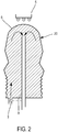
- the figure 2 shows another structure of the insert 20.
- the shell 2 constitutes the wall for containing the fluid to be heated, within this space the pipe 8 collects the fluid at the top of the insert.
- FIGS. 6 and 7 show in more detail the directions of circulation of the fluids within the boiler. Moreover, Figures 6 and 7 show the particular profiles of ferrules 2 and 4. It can be seen in particular that in zone A (according to figure 6 ), corresponding to the non-condensing zone, the segments that form the ferrules 2 and 4 are slightly inclined vis-à-vis the axis XX. In this way, the flows are very little deviated and we create reinforced exchanges on the heater 10 at the shell 4, essentially near the first end.
- the heat exchanges are favored. At this level there is creation of a condensation associated with the heating of the water as soon as it enters the boiler. These heat exchanges are here perfectly controlled and reinforced.
- the insert 20 is well irrigated and cooled. Note that the segments forming the ferrules 2 and 4 are here more inclined vis-à-vis the axis XX 'than those provided in the upper part A. Each ferrule 2, 4 is formed by a succession of segments inclined in one sense then in the other.
- the baffles formed promote heat exchange, especially in the zone B with condensation where the thermal exchange is greatly increased at the ferrule 2 of the insert. At this level the fumes come to impact or tap the insert while the heating body is in a slope that is to say less exposed to the smoke velocities. The heat exchange is therefore less important on the heating body.
- the temperature of the water and that of the fumes are close, for example around 30 ° C.
- the water reaches about 60 ° C or more.
- the temperature of the water is brought to approximately 50 ° C.
- the fumes produced by the burner reach 1700 ° C at the outlet of the burner 5, and they leave the boiler at about 30 ° C.
- Thermal exchanges are optimized by controlling these temperatures so that the inlet temperature of the water is close to that of the fumes at the outlet of the boiler.
- the boiler according to the invention therefore has non-condensing zones, the zones marked A on the figure 1 ; zones with condensation marked B on the figure 1 are also present.
- the boiler according to one aspect of the invention comprises a large central space, close to its longitudinal axis XX 'in order to reduce the volume of water and increase the water velocities.
- the preferred materials for the ferrules constituting the insert are steel, stainless steel or aluminum.
- the thicknesses of the walls are of the order of 0.7 mm; the height of the heating body is of the order of 60 cm its outer diameter of about 20 cm; the transfer duct 8 may have a diameter of about 2 cm.
- the annular passage section of the fumes is between 2000 and 3000 mm 2 in the zone A without condensation. This section can be between 1500 and 2000 mm 2 in zone B with condensation.
- the cross section of the water in the insert 20, between the ferrules 2 and 3 is between 1800 and 5000 mm 2 . At the level of the heating body 10, between the rings 1 and 4, the water passage section may commonly be between 1800 and 5000 mm 2 , depending on the location.
- the pressure losses in a boiler thus dimensioned are of the order of 350 Pa.
- the insert 20 is fixed on the heating body 10 by a connecting piece (not shown) disposed in the lower part of the boiler; It is also centered vis-à-vis the heating body by radially oriented protuberances of the insert, angularly spaced apart.
- the transfer pipe 8 is fixed on the insert by a connection known in itself; this pipe is fixed on the cylinder 1 by at least one connection.
- the diameters of the connecting pipes are of the order of 18 mm.
Priority Applications (1)
| Application Number | Priority Date | Filing Date | Title |
|---|---|---|---|
| PL18151033T PL3354997T3 (pl) | 2017-01-31 | 2018-01-10 | Kocioł o polepszonej wydajności |
Applications Claiming Priority (1)
| Application Number | Priority Date | Filing Date | Title |
|---|---|---|---|
| FR1750813A FR3062465A1 (fr) | 2017-01-31 | 2017-01-31 | Chaudiere a rendement ameliore. |
Publications (2)
| Publication Number | Publication Date |
|---|---|
| EP3354997A1 true EP3354997A1 (de) | 2018-08-01 |
| EP3354997B1 EP3354997B1 (de) | 2019-07-10 |
Family
ID=58707728
Family Applications (1)
| Application Number | Title | Priority Date | Filing Date |
|---|---|---|---|
| EP18151033.0A Active EP3354997B1 (de) | 2017-01-31 | 2018-01-10 | Heizkessel mit verbesserter leistung |
Country Status (5)
| Country | Link |
|---|---|
| EP (1) | EP3354997B1 (de) |
| ES (1) | ES2750247T3 (de) |
| FR (1) | FR3062465A1 (de) |
| PL (1) | PL3354997T3 (de) |
| PT (1) | PT3354997T (de) |
Cited By (1)
| Publication number | Priority date | Publication date | Assignee | Title |
|---|---|---|---|---|
| WO2020121211A1 (en) * | 2018-12-11 | 2020-06-18 | Stellenbosch University | Heat transfer device |
Citations (3)
| Publication number | Priority date | Publication date | Assignee | Title |
|---|---|---|---|---|
| FR1559461A (de) * | 1967-04-06 | 1969-03-07 | ||
| US5022379A (en) * | 1990-05-14 | 1991-06-11 | Wilson Jr James C | Coaxial dual primary heat exchanger |
| EP2012073A1 (de) * | 2007-02-05 | 2009-01-07 | Frisquet SA | Wärmetauscher für einen Kessel, Kessel mit so einem Wärmetauscher und Verfahren zur Anfertigung so eines Wärmetauschers |
-
2017
- 2017-01-31 FR FR1750813A patent/FR3062465A1/fr active Pending
-
2018
- 2018-01-10 PL PL18151033T patent/PL3354997T3/pl unknown
- 2018-01-10 EP EP18151033.0A patent/EP3354997B1/de active Active
- 2018-01-10 ES ES18151033T patent/ES2750247T3/es active Active
- 2018-01-10 PT PT181510330T patent/PT3354997T/pt unknown
Patent Citations (3)
| Publication number | Priority date | Publication date | Assignee | Title |
|---|---|---|---|---|
| FR1559461A (de) * | 1967-04-06 | 1969-03-07 | ||
| US5022379A (en) * | 1990-05-14 | 1991-06-11 | Wilson Jr James C | Coaxial dual primary heat exchanger |
| EP2012073A1 (de) * | 2007-02-05 | 2009-01-07 | Frisquet SA | Wärmetauscher für einen Kessel, Kessel mit so einem Wärmetauscher und Verfahren zur Anfertigung so eines Wärmetauschers |
Cited By (1)
| Publication number | Priority date | Publication date | Assignee | Title |
|---|---|---|---|---|
| WO2020121211A1 (en) * | 2018-12-11 | 2020-06-18 | Stellenbosch University | Heat transfer device |
Also Published As
| Publication number | Publication date |
|---|---|
| FR3062465A1 (fr) | 2018-08-03 |
| ES2750247T3 (es) | 2020-03-25 |
| PT3354997T (pt) | 2019-10-09 |
| EP3354997B1 (de) | 2019-07-10 |
| PL3354997T3 (pl) | 2020-03-31 |
Similar Documents
| Publication | Publication Date | Title |
|---|---|---|
| EP3405723B1 (de) | Kondensationswärmetauscher mit einer wärmetauschervorrichtung | |
| FR2997488A1 (fr) | Tube de transfert de chaleur et four craquage utilisant celui-ci. | |
| EP0192506B1 (de) | Fluidumerhitzer, insbesondere ein Brauchwasserspeicher | |
| EP3354997B1 (de) | Heizkessel mit verbesserter leistung | |
| EP2012073B1 (de) | Wärmetauscher für einen Kessel, Kessel mit so einem Wärmetauscher und Verfahren zur Anfertigung so eines Wärmetauschers | |
| EP0133604B1 (de) | Kessel mit spiralförmigem Wärmetauscher | |
| FR2570173A1 (fr) | Echangeur thermique, notamment pour chaudiere a condensation | |
| EP0329508A1 (de) | Zentralheizung mit Brauchwasserkreislauf | |
| FR2723632A1 (fr) | Dispositif d'echange de chaleur pour une chaudiere basse temperature | |
| FR2676272A1 (fr) | Echangeur de chaleur a faisceau tubulaire. | |
| FR2959000A1 (fr) | Conduit pour un circuit d'evacuation des produits de combustion et d'alimentation en air comburant dans une installation de fumisterie | |
| EP2251612A1 (de) | Elektrisches Heizgerät mit Wärmeübertragungsflüssigkeit, das aus gegossenen Modulelementen besteht | |
| EP1947386B1 (de) | Heizgaswirbler, insbesondere für Rauchrohrkessel und entsprechender Kessel | |
| EP1050721A1 (de) | Wärmetauscher für einen Heizkessel | |
| BE1006641A5 (fr) | Installation de chauffage central avec circuit d'eau chaude a usage domestique. | |
| EP0205374A1 (de) | Gasbeheizter industrieller Flüssigkeitserhitzer | |
| FR2853399A1 (fr) | Echangeur de chaleur helicoidal et chaudiere equipee d'un tel echangeur | |
| EP1464907B1 (de) | Wendelförmiger Wärmeaustauscher mit Rippen und Heizkessel mit solchem Wärmeaustauscher | |
| FR2760522A1 (fr) | Chaudiere destinee a etre montee sur un conduit d'evacuation de fumees de combustion | |
| FR2579313A1 (fr) | Echangeur de chaleur a tube double coude | |
| EP0030183B1 (de) | Heizkörper für mit Gas beheizte Haushaltskessel in Warmwasser-Zentralheizungen | |
| FR2664784A1 (fr) | Rechauffeur de fluide utilisant des tubes chauffes par effet joule qui transmettent leur energie simultanement par leurs faces interne et externe. | |
| FR2463368A1 (fr) | Corps de chauffe pour chaudieres domestiques de chauffage central a eau chaude par le gaz | |
| FR2817332A1 (fr) | Serpentin tubulaire a deux etages d'enroulements en spirale, echangeur de chaleur mettant en oeuvre un tel serpentin et procede de fabrication du serpentin | |
| CH287676A (fr) | Echangeur thermique. |
Legal Events
| Date | Code | Title | Description |
|---|---|---|---|
| PUAI | Public reference made under article 153(3) epc to a published international application that has entered the european phase |
Free format text: ORIGINAL CODE: 0009012 |
|
| STAA | Information on the status of an ep patent application or granted ep patent |
Free format text: STATUS: THE APPLICATION HAS BEEN PUBLISHED |
|
| AK | Designated contracting states |
Kind code of ref document: A1 Designated state(s): AL AT BE BG CH CY CZ DE DK EE ES FI FR GB GR HR HU IE IS IT LI LT LU LV MC MK MT NL NO PL PT RO RS SE SI SK SM TR |
|
| AX | Request for extension of the european patent |
Extension state: BA ME |
|
| STAA | Information on the status of an ep patent application or granted ep patent |
Free format text: STATUS: REQUEST FOR EXAMINATION WAS MADE |
|
| 17P | Request for examination filed |
Effective date: 20181226 |
|
| RBV | Designated contracting states (corrected) |
Designated state(s): AL AT BE BG CH CY CZ DE DK EE ES FI FR GB GR HR HU IE IS IT LI LT LU LV MC MK MT NL NO PL PT RO RS SE SI SK SM TR |
|
| GRAP | Despatch of communication of intention to grant a patent |
Free format text: ORIGINAL CODE: EPIDOSNIGR1 |
|
| STAA | Information on the status of an ep patent application or granted ep patent |
Free format text: STATUS: GRANT OF PATENT IS INTENDED |
|
| RIC1 | Information provided on ipc code assigned before grant |
Ipc: F24H 1/28 20060101AFI20190319BHEP Ipc: F28D 7/10 20060101ALI20190319BHEP Ipc: F24H 8/00 20060101ALI20190319BHEP Ipc: F28D 21/00 20060101ALI20190319BHEP Ipc: F24H 9/00 20060101ALI20190319BHEP Ipc: F28F 1/08 20060101ALI20190319BHEP Ipc: F28D 7/12 20060101ALI20190319BHEP Ipc: F28F 13/08 20060101ALI20190319BHEP Ipc: F24H 1/36 20060101ALI20190319BHEP |
|
| INTG | Intention to grant announced |
Effective date: 20190417 |
|
| GRAS | Grant fee paid |
Free format text: ORIGINAL CODE: EPIDOSNIGR3 |
|
| GRAA | (expected) grant |
Free format text: ORIGINAL CODE: 0009210 |
|
| STAA | Information on the status of an ep patent application or granted ep patent |
Free format text: STATUS: THE PATENT HAS BEEN GRANTED |
|
| AK | Designated contracting states |
Kind code of ref document: B1 Designated state(s): AL AT BE BG CH CY CZ DE DK EE ES FI FR GB GR HR HU IE IS IT LI LT LU LV MC MK MT NL NO PL PT RO RS SE SI SK SM TR |
|
| REG | Reference to a national code |
Ref country code: GB Ref legal event code: FG4D Free format text: NOT ENGLISH |
|
| REG | Reference to a national code |
Ref country code: CH Ref legal event code: EP Ref country code: AT Ref legal event code: REF Ref document number: 1154015 Country of ref document: AT Kind code of ref document: T Effective date: 20190715 |
|
| REG | Reference to a national code |
Ref country code: DE Ref legal event code: R096 Ref document number: 602018000214 Country of ref document: DE |
|
| REG | Reference to a national code |
Ref country code: IE Ref legal event code: FG4D Free format text: LANGUAGE OF EP DOCUMENT: FRENCH |
|
| REG | Reference to a national code |
Ref country code: PT Ref legal event code: SC4A Ref document number: 3354997 Country of ref document: PT Date of ref document: 20191009 Kind code of ref document: T Free format text: AVAILABILITY OF NATIONAL TRANSLATION Effective date: 20190920 |
|
| REG | Reference to a national code |
Ref country code: CH Ref legal event code: NV Representative=s name: E. BLUM AND CO. AG PATENT- UND MARKENANWAELTE , CH |
|
| REG | Reference to a national code |
Ref country code: NL Ref legal event code: MP Effective date: 20190710 |
|
| REG | Reference to a national code |
Ref country code: LT Ref legal event code: MG4D |
|
| REG | Reference to a national code |
Ref country code: AT Ref legal event code: MK05 Ref document number: 1154015 Country of ref document: AT Kind code of ref document: T Effective date: 20190710 |
|
| PG25 | Lapsed in a contracting state [announced via postgrant information from national office to epo] |
Ref country code: FI Free format text: LAPSE BECAUSE OF FAILURE TO SUBMIT A TRANSLATION OF THE DESCRIPTION OR TO PAY THE FEE WITHIN THE PRESCRIBED TIME-LIMIT Effective date: 20190710 Ref country code: LT Free format text: LAPSE BECAUSE OF FAILURE TO SUBMIT A TRANSLATION OF THE DESCRIPTION OR TO PAY THE FEE WITHIN THE PRESCRIBED TIME-LIMIT Effective date: 20190710 Ref country code: HR Free format text: LAPSE BECAUSE OF FAILURE TO SUBMIT A TRANSLATION OF THE DESCRIPTION OR TO PAY THE FEE WITHIN THE PRESCRIBED TIME-LIMIT Effective date: 20190710 Ref country code: SE Free format text: LAPSE BECAUSE OF FAILURE TO SUBMIT A TRANSLATION OF THE DESCRIPTION OR TO PAY THE FEE WITHIN THE PRESCRIBED TIME-LIMIT Effective date: 20190710 Ref country code: NO Free format text: LAPSE BECAUSE OF FAILURE TO SUBMIT A TRANSLATION OF THE DESCRIPTION OR TO PAY THE FEE WITHIN THE PRESCRIBED TIME-LIMIT Effective date: 20191010 Ref country code: AT Free format text: LAPSE BECAUSE OF FAILURE TO SUBMIT A TRANSLATION OF THE DESCRIPTION OR TO PAY THE FEE WITHIN THE PRESCRIBED TIME-LIMIT Effective date: 20190710 Ref country code: NL Free format text: LAPSE BECAUSE OF FAILURE TO SUBMIT A TRANSLATION OF THE DESCRIPTION OR TO PAY THE FEE WITHIN THE PRESCRIBED TIME-LIMIT Effective date: 20190710 Ref country code: BG Free format text: LAPSE BECAUSE OF FAILURE TO SUBMIT A TRANSLATION OF THE DESCRIPTION OR TO PAY THE FEE WITHIN THE PRESCRIBED TIME-LIMIT Effective date: 20191010 |
|
| PG25 | Lapsed in a contracting state [announced via postgrant information from national office to epo] |
Ref country code: RS Free format text: LAPSE BECAUSE OF FAILURE TO SUBMIT A TRANSLATION OF THE DESCRIPTION OR TO PAY THE FEE WITHIN THE PRESCRIBED TIME-LIMIT Effective date: 20190710 Ref country code: AL Free format text: LAPSE BECAUSE OF FAILURE TO SUBMIT A TRANSLATION OF THE DESCRIPTION OR TO PAY THE FEE WITHIN THE PRESCRIBED TIME-LIMIT Effective date: 20190710 Ref country code: LV Free format text: LAPSE BECAUSE OF FAILURE TO SUBMIT A TRANSLATION OF THE DESCRIPTION OR TO PAY THE FEE WITHIN THE PRESCRIBED TIME-LIMIT Effective date: 20190710 Ref country code: GR Free format text: LAPSE BECAUSE OF FAILURE TO SUBMIT A TRANSLATION OF THE DESCRIPTION OR TO PAY THE FEE WITHIN THE PRESCRIBED TIME-LIMIT Effective date: 20191011 Ref country code: IS Free format text: LAPSE BECAUSE OF FAILURE TO SUBMIT A TRANSLATION OF THE DESCRIPTION OR TO PAY THE FEE WITHIN THE PRESCRIBED TIME-LIMIT Effective date: 20191110 |
|
| REG | Reference to a national code |
Ref country code: ES Ref legal event code: FG2A Ref document number: 2750247 Country of ref document: ES Kind code of ref document: T3 Effective date: 20200325 |
|
| PG25 | Lapsed in a contracting state [announced via postgrant information from national office to epo] |
Ref country code: TR Free format text: LAPSE BECAUSE OF FAILURE TO SUBMIT A TRANSLATION OF THE DESCRIPTION OR TO PAY THE FEE WITHIN THE PRESCRIBED TIME-LIMIT Effective date: 20190710 |
|
| PG25 | Lapsed in a contracting state [announced via postgrant information from national office to epo] |
Ref country code: EE Free format text: LAPSE BECAUSE OF FAILURE TO SUBMIT A TRANSLATION OF THE DESCRIPTION OR TO PAY THE FEE WITHIN THE PRESCRIBED TIME-LIMIT Effective date: 20190710 Ref country code: RO Free format text: LAPSE BECAUSE OF FAILURE TO SUBMIT A TRANSLATION OF THE DESCRIPTION OR TO PAY THE FEE WITHIN THE PRESCRIBED TIME-LIMIT Effective date: 20190710 Ref country code: DK Free format text: LAPSE BECAUSE OF FAILURE TO SUBMIT A TRANSLATION OF THE DESCRIPTION OR TO PAY THE FEE WITHIN THE PRESCRIBED TIME-LIMIT Effective date: 20190710 |
|
| PG25 | Lapsed in a contracting state [announced via postgrant information from national office to epo] |
Ref country code: SK Free format text: LAPSE BECAUSE OF FAILURE TO SUBMIT A TRANSLATION OF THE DESCRIPTION OR TO PAY THE FEE WITHIN THE PRESCRIBED TIME-LIMIT Effective date: 20190710 Ref country code: IS Free format text: LAPSE BECAUSE OF FAILURE TO SUBMIT A TRANSLATION OF THE DESCRIPTION OR TO PAY THE FEE WITHIN THE PRESCRIBED TIME-LIMIT Effective date: 20200224 Ref country code: SM Free format text: LAPSE BECAUSE OF FAILURE TO SUBMIT A TRANSLATION OF THE DESCRIPTION OR TO PAY THE FEE WITHIN THE PRESCRIBED TIME-LIMIT Effective date: 20190710 Ref country code: CZ Free format text: LAPSE BECAUSE OF FAILURE TO SUBMIT A TRANSLATION OF THE DESCRIPTION OR TO PAY THE FEE WITHIN THE PRESCRIBED TIME-LIMIT Effective date: 20190710 |
|
| REG | Reference to a national code |
Ref country code: DE Ref legal event code: R097 Ref document number: 602018000214 Country of ref document: DE |
|
| PLBE | No opposition filed within time limit |
Free format text: ORIGINAL CODE: 0009261 |
|
| STAA | Information on the status of an ep patent application or granted ep patent |
Free format text: STATUS: NO OPPOSITION FILED WITHIN TIME LIMIT |
|
| PG2D | Information on lapse in contracting state deleted |
Ref country code: IS |
|
| 26N | No opposition filed |
Effective date: 20200603 |
|
| PG25 | Lapsed in a contracting state [announced via postgrant information from national office to epo] |
Ref country code: SI Free format text: LAPSE BECAUSE OF FAILURE TO SUBMIT A TRANSLATION OF THE DESCRIPTION OR TO PAY THE FEE WITHIN THE PRESCRIBED TIME-LIMIT Effective date: 20190710 Ref country code: MC Free format text: LAPSE BECAUSE OF FAILURE TO SUBMIT A TRANSLATION OF THE DESCRIPTION OR TO PAY THE FEE WITHIN THE PRESCRIBED TIME-LIMIT Effective date: 20190710 |
|
| PG25 | Lapsed in a contracting state [announced via postgrant information from national office to epo] |
Ref country code: LU Free format text: LAPSE BECAUSE OF NON-PAYMENT OF DUE FEES Effective date: 20200110 |
|
| PG25 | Lapsed in a contracting state [announced via postgrant information from national office to epo] |
Ref country code: IE Free format text: LAPSE BECAUSE OF NON-PAYMENT OF DUE FEES Effective date: 20200110 |
|
| PG25 | Lapsed in a contracting state [announced via postgrant information from national office to epo] |
Ref country code: MT Free format text: LAPSE BECAUSE OF FAILURE TO SUBMIT A TRANSLATION OF THE DESCRIPTION OR TO PAY THE FEE WITHIN THE PRESCRIBED TIME-LIMIT Effective date: 20190710 Ref country code: CY Free format text: LAPSE BECAUSE OF FAILURE TO SUBMIT A TRANSLATION OF THE DESCRIPTION OR TO PAY THE FEE WITHIN THE PRESCRIBED TIME-LIMIT Effective date: 20190710 |
|
| PG25 | Lapsed in a contracting state [announced via postgrant information from national office to epo] |
Ref country code: MK Free format text: LAPSE BECAUSE OF FAILURE TO SUBMIT A TRANSLATION OF THE DESCRIPTION OR TO PAY THE FEE WITHIN THE PRESCRIBED TIME-LIMIT Effective date: 20190710 |
|
| PGFP | Annual fee paid to national office [announced via postgrant information from national office to epo] |
Ref country code: FR Payment date: 20230130 Year of fee payment: 6 Ref country code: ES Payment date: 20230201 Year of fee payment: 6 Ref country code: CH Payment date: 20230116 Year of fee payment: 6 |
|
| PGFP | Annual fee paid to national office [announced via postgrant information from national office to epo] |
Ref country code: PL Payment date: 20230105 Year of fee payment: 6 Ref country code: IT Payment date: 20230127 Year of fee payment: 6 Ref country code: BE Payment date: 20230131 Year of fee payment: 6 |
|
| PGFP | Annual fee paid to national office [announced via postgrant information from national office to epo] |
Ref country code: ES Payment date: 20240201 Year of fee payment: 7 |
|
| PGFP | Annual fee paid to national office [announced via postgrant information from national office to epo] |
Ref country code: DE Payment date: 20240129 Year of fee payment: 7 Ref country code: GB Payment date: 20240109 Year of fee payment: 7 Ref country code: PT Payment date: 20240109 Year of fee payment: 7 Ref country code: CH Payment date: 20240202 Year of fee payment: 7 |