EP3354970A1 - Lighting device for vehicles having an aesthetic mask - Google Patents
Lighting device for vehicles having an aesthetic mask Download PDFInfo
- Publication number
- EP3354970A1 EP3354970A1 EP17154080.0A EP17154080A EP3354970A1 EP 3354970 A1 EP3354970 A1 EP 3354970A1 EP 17154080 A EP17154080 A EP 17154080A EP 3354970 A1 EP3354970 A1 EP 3354970A1
- Authority
- EP
- European Patent Office
- Prior art keywords
- lighting device
- individual
- bulged
- inlet opening
- complex curved
- Prior art date
- Legal status (The legal status is an assumption and is not a legal conclusion. Google has not performed a legal analysis and makes no representation as to the accuracy of the status listed.)
- Granted
Links
Images

Classifications
-
- F—MECHANICAL ENGINEERING; LIGHTING; HEATING; WEAPONS; BLASTING
- F21—LIGHTING
- F21S—NON-PORTABLE LIGHTING DEVICES; SYSTEMS THEREOF; VEHICLE LIGHTING DEVICES SPECIALLY ADAPTED FOR VEHICLE EXTERIORS
- F21S41/00—Illuminating devices specially adapted for vehicle exteriors, e.g. headlamps
- F21S41/50—Illuminating devices specially adapted for vehicle exteriors, e.g. headlamps characterised by aesthetic components not otherwise provided for, e.g. decorative trim, partition walls or covers
-
- F—MECHANICAL ENGINEERING; LIGHTING; HEATING; WEAPONS; BLASTING
- F21—LIGHTING
- F21S—NON-PORTABLE LIGHTING DEVICES; SYSTEMS THEREOF; VEHICLE LIGHTING DEVICES SPECIALLY ADAPTED FOR VEHICLE EXTERIORS
- F21S41/00—Illuminating devices specially adapted for vehicle exteriors, e.g. headlamps
- F21S41/30—Illuminating devices specially adapted for vehicle exteriors, e.g. headlamps characterised by reflectors
- F21S41/32—Optical layout thereof
- F21S41/323—Optical layout thereof the reflector having two perpendicular cross sections having regular geometrical curves of a distinct nature
-
- F—MECHANICAL ENGINEERING; LIGHTING; HEATING; WEAPONS; BLASTING
- F21—LIGHTING
- F21S—NON-PORTABLE LIGHTING DEVICES; SYSTEMS THEREOF; VEHICLE LIGHTING DEVICES SPECIALLY ADAPTED FOR VEHICLE EXTERIORS
- F21S41/00—Illuminating devices specially adapted for vehicle exteriors, e.g. headlamps
- F21S41/30—Illuminating devices specially adapted for vehicle exteriors, e.g. headlamps characterised by reflectors
- F21S41/32—Optical layout thereof
- F21S41/33—Multi-surface reflectors, e.g. reflectors with facets or reflectors with portions of different curvature
- F21S41/334—Multi-surface reflectors, e.g. reflectors with facets or reflectors with portions of different curvature the reflector consisting of patch like sectors
- F21S41/336—Multi-surface reflectors, e.g. reflectors with facets or reflectors with portions of different curvature the reflector consisting of patch like sectors with discontinuity at the junction between adjacent areas
Definitions
- the present invention relates to a lighting device equipped with at least one lighting module and with an aesthetic mask.
- Lighting devices for vehicles provided with multiple optical modules are known in the art.
- EP2957822 discloses a lighting device including a rotating module including a fixed reflector, a fixed light source aligned with an axis, and a couple of opposite screens rotating around the axis under the action of a motor actuator; the two screens embody two lenses, e.g. one provided with prisms and one neutral, in order to change the light distribution provided by the light source and the reflector when each of the screens is selectively rotated in front of the reflector.
- the lighting devices of the prior art provided with one or more rotating modules like e.g. that one of EP2957822 need actuation mechanisms to operate the rotating modules.
- those mechanisms may be seen from the outside due to the fact that the modern lighting devices are generally provided with outer transparent covers/lens through which the lighting modules are visible. The lighting devices need therefore to be provided with an aesthetic mask to cover the actuating mechanisms.
- An aesthetic mask may be also necessary in lighting devices having one or more stationary lighting modules in order to join the profile of each lighting module with the overall profile of the lighting device, which generally have to follow the aesthetic profile of the vehicle, and/or to cover possible gaps caused by the mounting in the same housing body of the lighting device of different lighting modules.
- Such aesthetic masks are usually placed between the lighting modules and the outer transparent cover to close a gap between the lighting modules and the outer profile of the housing body and may be provided with metallized surfaces which may be reflective.
- parasite light rays may be generated by the reflective surfaces of the aesthetic mask.
- the parasite rays may cause undesired light distributions or even the dazzling of the drivers of other vehicles.
- the object of the present invention is to provide a lighting device for vehicles having an housing body, one or more lighting modules arranged therein, which are visible from the outside of the housing body, and at least one aesthetic mask arranged in a gap between the lighting modules and an outer profile of the housing body, wherein the risk of dazzling of crossing vehicles due to parasite rays is avoided or at least greatly reduced when one or more lighting modules are switched on.
- a lighting device for vehicles having the features set out in the appended claims.
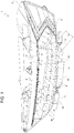
- reference numeral 1 indicates as a whole a lighting device for vehicles consisting, in the non-limiting embodiment shown, in a vehicle headlight, which is only in part and only schematically shown. It is however to be intended that what will be described can be applied to any vehicle lighting device.
- the lighting device 1 comprises a generally cup-shaped housing body 2 designed to be mounted on a vehicle, known and not shown for sake of simplicity.
- Housing body 2 is made of synthetic plastic material by injection molding and has a front inlet opening 3 in use facing opposite to the vehicle and towards a driving or march direction of the vehicle, closed by a transparent cover, preferably consisting in a transparent lens not provided with optical functions ("terse" lens), well known and not shown for sake of simplicity.
- the housing body 2 carries at the interior thereof at least one (or more) first lighting module 5, which is in the embodiment shown the main lighting module of the lighting device 1, e.g. is a cross-beam light or high beam light, and, possibly, a plurality of secondary lighting modules 6, well known and shown in dotted line and only schematically for sake of simplicity; the secondary lighting modules 6, when present, are designed to provide additional optical functions, all together or singularly, and may be either stationary or rotatable about an axis transverse to an optical axis OA ( figure 2 ) of the main lighting module 5.
- first lighting module 5 which is in the embodiment shown the main lighting module of the lighting device 1, e.g. is a cross-beam light or high beam light, and, possibly, a plurality of secondary lighting modules 6, well known and shown in dotted line and only schematically for sake of simplicity; the secondary lighting modules 6, when present, are designed to provide additional optical functions, all together or singularly, and may be either stationary or rotatable about an axis transverse to an optical
- optical axis it is intended herein and below a geometrical axis according with the light rays generated by the lighting module 5 are delivered.
- the lighting modules 5,6 are all visible from the outside through the inlet opening 3 and the transparent cover, and are arranged side by side facing the inlet opening 3.
- the lighting modules 5,6 are spaced apart from the inlet opening 3 so that the lighting device 1 also comprises an aesthetic mask 7 to cover a gap G arranged between the inlet opening 3 and the lighting modules 5,6.
- the aesthetic mask 7 extends parallel to the aforementioned gap G in a substantially horizontal direction and along the full width of the inlet opening 3, transverse the optical axis OA of the first (main) lighting module 5, which optical axis OA is oriented in use in the driving direction of the vehicle.
- the aesthetic mask 7 is delimited towards the lighting modules 5,6 by an upper surface 8 which hides the gap G.
- the upper surface 8 is formed by a plurality of individual surface portions 9,10 arranged adjacent to one another, wherein at least part of the individual surface portions, namely portions 9 in the example shown, are bulged upwards.
- the individual surface portions 9 bulged upwards are delimited by at least one first complex curved surface 11 which is continuous.
- each first complex curved surface 11 of each bulged surface portion 9 is defined by the convolution of a first spline curve 12 and a second spline curve 13, each first complex curved surface 11 having been generated by the translation of the second spline curve 13 along the first spline curve 12; it is also possible the contrary, according to the circumstances, i.e. each first complex curved surface 11 may be generated by the translation of the first spline curve 12 along the second spline curve 13.
- spline curve it is intended a geometrical curve generated by graphic interpolation of a set of pre-established points.
- a spline is a numeric function that is piecewise-defined by polynomial functions, and which possesses a high degree of smoothness at the places where the polynomial pieces connect (which are known as knots).
- knots which are known as knots.
- spline interpolation is often preferred to purely polynomial interpolation, because it yields similar results to interpolating with higher degree polynomials while avoiding instability due to Runge's phenomenon.
- parametric curves whose coordinates are given by splines are popular because of the simplicity of their construction, their ease and accuracy of evaluation, and their capacity to approximate complex shapes through curve fitting and interactive curve design.
- the most commonly used splines are cubic splines, i.e., of order 3 - in particular, cubic B-spline, which is equivalent to C2 continuous composite Bézier curves.
- all the individual surface portions 9 bulged upwards are delimited by the one first complex curved surface 11 and by one second complex curved surface 14, which is continuous and which is also defined by the convolution of a first and a second complex curved surfaces, like as schematically shown in figure 3 ; however, according to an aspect of the present invention, the first and second complex curved surfaces (not shown) defining the complex curved surface 14 have curvatures opposite to those of the curves 12 and 13, so that the first and second complex curved surfaces 11,14 have opposite curvatures.
- the second complex curved surface 14 of each bulged surface portion 9 is arranged immediately adjacent to the first complex curved surface 11 and is separated therefrom by a mathematical discontinuity (a cusp) forming a separation edge 15 between the first and the second complex curved surfaces.
- the separation edge 15 is also curved and defines the top of each individual bulged surface portion 9; the separation edges 15 of the bulged surface portions 9 are all oriented substantially parallel to the optical axis OA of the lighting module 5, namely in the travel direction of the vehicle on which the lighting device 1 is mounted.
- the whole upper surface 8 of the aesthetic mask 7 bears the individual bulged surface portions 9, which constitute almost the whole upper surface 8; the remaining of the upper surface 8 is constituted in the non-limiting embodiment shown by a single surface portion 10 which is substantially flat and plane and which define a forward rim 16 of the aesthetic mask 7.
- the individual bulged surface portions 9 are arranged in a checkerboard configuration, along at least two parallel rows, as well shown in figure 1 , running in the direction of the width of the front inlet opening 3.
- each individual bulged surface portion 9 defines with another adjacent individual bulged surface portion 9 a separation step 18; all the separation steps are oriented forwards and their height increases progressively in the forward direction, as well shown in figure 4 , so that each bulged surface portion 9 is flush with the surface portion 10 on the side facing the lighting modules 5,6 and then progressively raises above the surface portion 10, raising more at the separation edge 15.
- the separation steps 18 also separate the forward row of adjacent bulged surface portions 9 by the flat surface portion 10.
- the upper surface 8 of the aesthetic mask 7 is preferably reflective, e.g. it has been metallized, since the mask 7 is usually made in synthetic plastic material by injection molding, and the bulged surface portions are of a generally prismatic shape owing to a polygonal, e.g. square, shape in plant and owing to the presence of the separation edges 15 and the separation steps 18, so that the whole upper surface 8 has a diamond-like appearance.
- each bulged surface portion 9 is convex close to the separation step 18 and becomes concave on the opposite side, forming a mathematical flex.
- Surface 14 is opposite, being concave close to the separation step 18 and becomes convex on the opposite side, also forming a mathematical flex.
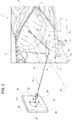
- figure 2 is also schematically represented how the invention works.
- test screen 20 is indicated a standard test screen, only schematically represented.
- This test screen is an opaque screen set in front of the lighting device under test and at 25 m distance therefrom, upon which the light rays generated by the lighting device under test are projected. On the test screen 20, therefore, it is reproduced the light distribution obtainable by the lighting device under test.
- the lighting module 5 When the lighting module 5 is switched on, if the upper surface 8 is made reflective (usually both for aesthetic and technical reasons) some light rays 21 emitted by the lighting devices 5,6 may hit the surface 8 and are reflected by the same: in the schematic example shown one such light ray 21 may form on the screen 20 a projection point 22.
- the upper surface 8 was flat, or even if it was shaped to have a diamond-like aspect and the surfaces 11,14 of the bulged surface portions 9 were inclined but flat, the light rays 21 reflected by the surface 8 would be almost parallel and therefore they would form on the test screen 20 a projection 23 quite small (they would be close to each other) and accordingly having more light concentration: in this condition, if the light rays were reflected upwards, they would possibly dazzle incoming drivers even if only position lights or dipped beam lights were switched on.
- the surfaces 11,14 are calculated in order to continuously vary the orientation of the normal (line perpendicular) to each point of the surface, so that the light rays possibly reflected by the upper surface 8 are spread upon a larger surface and so form a larger projection 24 on the test screen 20; projection 24 has a light concentration so low that no dazzling effect may occur.
Landscapes
- Engineering & Computer Science (AREA)
- General Engineering & Computer Science (AREA)
- Physics & Mathematics (AREA)
- Geometry (AREA)
- Non-Portable Lighting Devices Or Systems Thereof (AREA)
Abstract
Description
- The present invention relates to a lighting device equipped with at least one lighting module and with an aesthetic mask.
- Lighting devices for vehicles provided with multiple optical modules are known in the art.
-
EP2957822 discloses a lighting device including a rotating module including a fixed reflector, a fixed light source aligned with an axis, and a couple of opposite screens rotating around the axis under the action of a motor actuator; the two screens embody two lenses, e.g. one provided with prisms and one neutral, in order to change the light distribution provided by the light source and the reflector when each of the screens is selectively rotated in front of the reflector. - The lighting devices of the prior art provided with one or more rotating modules like e.g. that one of
EP2957822 need actuation mechanisms to operate the rotating modules. Unfortunately, those mechanisms may be seen from the outside due to the fact that the modern lighting devices are generally provided with outer transparent covers/lens through which the lighting modules are visible. The lighting devices need therefore to be provided with an aesthetic mask to cover the actuating mechanisms. - An aesthetic mask may be also necessary in lighting devices having one or more stationary lighting modules in order to join the profile of each lighting module with the overall profile of the lighting device, which generally have to follow the aesthetic profile of the vehicle, and/or to cover possible gaps caused by the mounting in the same housing body of the lighting device of different lighting modules.
- Such aesthetic masks are usually placed between the lighting modules and the outer transparent cover to close a gap between the lighting modules and the outer profile of the housing body and may be provided with metallized surfaces which may be reflective.
- When one or more lighting modules are switched on, parasite light rays may be generated by the reflective surfaces of the aesthetic mask. The parasite rays may cause undesired light distributions or even the dazzling of the drivers of other vehicles.
- The object of the present invention is to provide a lighting device for vehicles having an housing body, one or more lighting modules arranged therein, which are visible from the outside of the housing body, and at least one aesthetic mask arranged in a gap between the lighting modules and an outer profile of the housing body, wherein the risk of dazzling of crossing vehicles due to parasite rays is avoided or at least greatly reduced when one or more lighting modules are switched on.
- According to the invention, a lighting device for vehicles is provided having the features set out in the appended claims.
- Further features and advantages of the present invention will become more apparent from the following description of one non-limiting embodiment thereof, made with reference to the figures in the accompanying drawings, in which:
-
figure 1 shows schematically a perspective front elevation view of a lighting device for a vehicle, with parts removed for simplicity, realized according to the invention; -
figure 2 shows schematically in an enlarged scale a detail of the lighting device offigure 1 and depicts schematically the principle of operation of the invention; -
figure 3 shows schematically and further in an enlarged scale a perspective view of a geometrical surface embodied in the lighting device of the invention; and -
figure 4 shows schematically and further in an enlarged scale a detail offigure 2 . - With reference to
figures 1 and2 ,reference numeral 1 indicates as a whole a lighting device for vehicles consisting, in the non-limiting embodiment shown, in a vehicle headlight, which is only in part and only schematically shown. It is however to be intended that what will be described can be applied to any vehicle lighting device. - The
lighting device 1 comprises a generally cup-shaped housing body 2 designed to be mounted on a vehicle, known and not shown for sake of simplicity.Housing body 2 is made of synthetic plastic material by injection molding and has a front inlet opening 3 in use facing opposite to the vehicle and towards a driving or march direction of the vehicle, closed by a transparent cover, preferably consisting in a transparent lens not provided with optical functions ("terse" lens), well known and not shown for sake of simplicity. - The
housing body 2 carries at the interior thereof at least one (or more)first lighting module 5, which is in the embodiment shown the main lighting module of thelighting device 1, e.g. is a cross-beam light or high beam light, and, possibly, a plurality ofsecondary lighting modules 6, well known and shown in dotted line and only schematically for sake of simplicity; thesecondary lighting modules 6, when present, are designed to provide additional optical functions, all together or singularly, and may be either stationary or rotatable about an axis transverse to an optical axis OA (figure 2 ) of themain lighting module 5. - For "optical axis" it is intended herein and below a geometrical axis according with the light rays generated by the
lighting module 5 are delivered. - The
lighting modules - The
lighting modules lighting device 1 also comprises anaesthetic mask 7 to cover a gap G arranged between theinlet opening 3 and thelighting modules - The
aesthetic mask 7 extends parallel to the aforementioned gap G in a substantially horizontal direction and along the full width of theinlet opening 3, transverse the optical axis OA of the first (main)lighting module 5, which optical axis OA is oriented in use in the driving direction of the vehicle. - The
aesthetic mask 7 is delimited towards thelighting modules upper surface 8 which hides the gap G. According to one main aspect of the present invention, theupper surface 8 is formed by a plurality ofindividual surface portions portions 9 in the example shown, are bulged upwards. - The
individual surface portions 9 bulged upwards are delimited by at least one first complexcurved surface 11 which is continuous. - With reference to
figure 3 , where an example of asurface 11 is shown only schematically and out of scale, the first complexcurved surface 11 of each bulgedsurface portion 9 is defined by the convolution of afirst spline curve 12 and asecond spline curve 13, each first complexcurved surface 11 having been generated by the translation of thesecond spline curve 13 along thefirst spline curve 12; it is also possible the contrary, according to the circumstances, i.e. each first complexcurved surface 11 may be generated by the translation of thefirst spline curve 12 along thesecond spline curve 13. - Here and below, for "spline curve" it is intended a geometrical curve generated by graphic interpolation of a set of pre-established points. In mathematics, a spline is a numeric function that is piecewise-defined by polynomial functions, and which possesses a high degree of smoothness at the places where the polynomial pieces connect (which are known as knots). In interpolation problems, spline interpolation is often preferred to purely polynomial interpolation, because it yields similar results to interpolating with higher degree polynomials while avoiding instability due to Runge's phenomenon. In computer graphics, parametric curves whose coordinates are given by splines are popular because of the simplicity of their construction, their ease and accuracy of evaluation, and their capacity to approximate complex shapes through curve fitting and interactive curve design.
- The most commonly used splines are cubic splines, i.e., of order 3 - in particular, cubic B-spline, which is equivalent to C2 continuous composite Bézier curves.
- In the preferred embodiment shown, all the
individual surface portions 9 bulged upwards are delimited by the one first complexcurved surface 11 and by one second complexcurved surface 14, which is continuous and which is also defined by the convolution of a first and a second complex curved surfaces, like as schematically shown infigure 3 ; however, according to an aspect of the present invention, the first and second complex curved surfaces (not shown) defining the complexcurved surface 14 have curvatures opposite to those of thecurves curved surfaces - With reference to
figure 4 too, the second complexcurved surface 14 of each bulgedsurface portion 9 is arranged immediately adjacent to the first complexcurved surface 11 and is separated therefrom by a mathematical discontinuity (a cusp) forming aseparation edge 15 between the first and the second complex curved surfaces. - The
separation edge 15 is also curved and defines the top of each individual bulgedsurface portion 9; theseparation edges 15 of the bulgedsurface portions 9 are all oriented substantially parallel to the optical axis OA of thelighting module 5, namely in the travel direction of the vehicle on which thelighting device 1 is mounted. - In the example shown, where substantially the whole width of the
inlet opening 3 is occupied by thelighting modules upper surface 8 of theaesthetic mask 7 bears the individual bulgedsurface portions 9, which constitute almost the wholeupper surface 8; the remaining of theupper surface 8 is constituted in the non-limiting embodiment shown by asingle surface portion 10 which is substantially flat and plane and which define aforward rim 16 of theaesthetic mask 7. - The individual bulged
surface portions 9 are arranged in a checkerboard configuration, along at least two parallel rows, as well shown infigure 1 , running in the direction of the width of thefront inlet opening 3. - Moreover, according to a further aspect of the invention, each individual bulged
surface portion 9 defines with another adjacent individual bulged surface portion 9 aseparation step 18; all the separation steps are oriented forwards and their height increases progressively in the forward direction, as well shown infigure 4 , so that each bulgedsurface portion 9 is flush with thesurface portion 10 on the side facing thelighting modules surface portion 10, raising more at theseparation edge 15. - The
separation steps 18 also separate the forward row of adjacent bulgedsurface portions 9 by theflat surface portion 10. - The
upper surface 8 of theaesthetic mask 7 is preferably reflective, e.g. it has been metallized, since themask 7 is usually made in synthetic plastic material by injection molding, and the bulged surface portions are of a generally prismatic shape owing to a polygonal, e.g. square, shape in plant and owing to the presence of theseparation edges 15 and theseparation steps 18, so that the wholeupper surface 8 has a diamond-like appearance. - According to a further aspect of the invention (
figure 4 )surface 11 of each bulgedsurface portion 9 is convex close to theseparation step 18 and becomes concave on the opposite side, forming a mathematical flex.Surface 14 is opposite, being concave close to theseparation step 18 and becomes convex on the opposite side, also forming a mathematical flex. - In
figure 2 is also schematically represented how the invention works. - With
reference number 20, it is indicated a standard test screen, only schematically represented. This test screen, as it is well known to the skilled in the art, is an opaque screen set in front of the lighting device under test and at 25 m distance therefrom, upon which the light rays generated by the lighting device under test are projected. On thetest screen 20, therefore, it is reproduced the light distribution obtainable by the lighting device under test. - When the
lighting module 5 is switched on, if theupper surface 8 is made reflective (usually both for aesthetic and technical reasons) somelight rays 21 emitted by thelighting devices surface 8 and are reflected by the same: in the schematic example shown onesuch light ray 21 may form on the screen 20 aprojection point 22. - If the
upper surface 8 was flat, or even if it was shaped to have a diamond-like aspect and thesurfaces surface portions 9 were inclined but flat, thelight rays 21 reflected by thesurface 8 would be almost parallel and therefore they would form on the test screen 20 aprojection 23 quite small (they would be close to each other) and accordingly having more light concentration: in this condition, if the light rays were reflected upwards, they would possibly dazzle incoming drivers even if only position lights or dipped beam lights were switched on. - According to the invention, on the contrary, the
surfaces upper surface 8 are spread upon a larger surface and so form alarger projection 24 on thetest screen 20;projection 24 has a light concentration so low that no dazzling effect may occur. - In order to calculate
surfaces - 1) Firstly a first point of the surface under calculation is arbitrary chosen, and for this first surface point is calculated the position on the
test screen 20 of theprojection point 22 of a light rays reflected by it in the hypothesis e.g. of switching onlighting module 5. - 2) Secondly, it is established the position on the test screen of at least four
projection points 25 taken in such a manner to be at the edge of an hypothetic light projection having no dazzling effects. - 3) For these four projection points it is calculated which would have to be the inclination of the normal to the reflective surface to be calculated at the first point of such surface previously selected at item 1) above.
- 4) Then a set of second points of the surface to be calculated are determined having their normal to the surface oriented in such a manner to have projection points on the
screen 20 arranged within the hypothetic light projection having no dazzling effects. - 5) On the basis of the orientation of the normal previously determined and of the position of the second points,
curves - 6) Finally, the
whole surface curve 12 translate alongcurve 13 or vice-versa. - In this manner it may be obtained an aesthetic mask which is reflective and has a diamond-like appearance, without any risk that the switching on of the
lighting modules mask 7. - All the aims of the invention are therefore accomplished.
Claims (9)
- Lighting device (1) for a vehicle comprising a cup-shaped housing body (2) designed to be mounted on a vehicle body and having a front inlet opening (3) facing in use a forward march direction of the vehicle, at least one lighting module (5) arranged inside the housing body facing the inlet opening and spaced apart from the inlet opening (3), the lighting module (5;6) being visible from the outside through the inlet opening (3), and an aesthetic mask (7) to cover a gap (G) between the inlet opening and the at least one light module, the aesthetic mask (7) extending parallel to said gap in a substantially horizontal direction and being delimited towards the at least one lighting module (5;6) by an upper surface (8) which hides the gap (G); characterized in that:i)- the upper surface (8) is formed by a plurality of individual surface portions (9,10) arranged adjacent to one another;ii)- at least part of said individual surface portions (9) are bulged upwards, andiii)- the individual surface portions (9) bulged upwards are delimited by at least one first complex curved surface (11) which is continuous and which is defined by the convolution of a first (12) and a second (13) spline curve,iv)- each first complex curved surface (11) having been generated by the translation of the second spline curve (13) along the first spline curve (12) or vice-versa.
- Lighting device (1) according to claim 1, characterized in that all the individual surface portions bulged upwards (9) are delimited by said one first complex curved surface (11) and by one second complex curved surface (14) which is continuous and which is also defined by the convolution of a first and a second spline curve (12,13); the second complex curved surface (14) being arranged immediately adjacent to the first one (11) and being separated from the first one by a mathematical discontinuity forming a separation edge (15) between the first and the second complex curved surfaces.
- Lighting device according to claim 2, characterized in that the separation edge (15) define the top of each individual bulged surface portion and is oriented substantially parallel to an optical axis (OA) of the at least one lighting module.
- Lighting device according to claim 2 or 3, characterized in that the first and second complex curved surfaces (11,14) have opposite curvatures.
- Lighting device according to anyone of the preceding claims, characterized in that the whole upper surface (8) of the aesthetic mask (7) bears said individual bulged surface portions (9).
- Lighting device according to claim 5, characterized in that the individual bulged surface portions (9) are arranged in a checkerboard configuration, along at least two parallel rows running in the direction of the width of said front inlet opening (3).
- Lighting device according to anyone of the preceding claims, characterized in that each individual bulged surface portion (9) define with another adjacent individual bulged surface portion (9) a separation step (18); all the separation steps (18) being oriented forwards.
- Lighting device according to anyone of the preceding claims, characterized in that the upper surface (8) of the aesthetic mask (7) is reflective.
- Vehicle provided with a lighting device (1) according to claim 1.
Priority Applications (2)
| Application Number | Priority Date | Filing Date | Title |
|---|---|---|---|
| EP17154080.0A EP3354970B1 (en) | 2017-01-31 | 2017-01-31 | Lighting device for vehicles having an aesthetic mask |
| CN201810096194.8A CN108916808B (en) | 2017-01-31 | 2018-01-31 | Lighting device for vehicle with aesthetic mask |
Applications Claiming Priority (1)
| Application Number | Priority Date | Filing Date | Title |
|---|---|---|---|
| EP17154080.0A EP3354970B1 (en) | 2017-01-31 | 2017-01-31 | Lighting device for vehicles having an aesthetic mask |
Publications (2)
| Publication Number | Publication Date |
|---|---|
| EP3354970A1 true EP3354970A1 (en) | 2018-08-01 |
| EP3354970B1 EP3354970B1 (en) | 2020-04-29 |
Family
ID=57963032
Family Applications (1)
| Application Number | Title | Priority Date | Filing Date |
|---|---|---|---|
| EP17154080.0A Active EP3354970B1 (en) | 2017-01-31 | 2017-01-31 | Lighting device for vehicles having an aesthetic mask |
Country Status (2)
| Country | Link |
|---|---|
| EP (1) | EP3354970B1 (en) |
| CN (1) | CN108916808B (en) |
Citations (7)
| Publication number | Priority date | Publication date | Assignee | Title |
|---|---|---|---|---|
| GB2253046A (en) * | 1991-02-08 | 1992-08-26 | Koito Mfg Co Ltd | Projection-type vehicle headlamp |
| FR2709811A1 (en) * | 1993-09-09 | 1995-03-17 | Valeo Vision | Headlight with improved interior aspect for motor vehicles |
| JPH09129003A (en) * | 1995-11-02 | 1997-05-16 | Koito Mfg Co Ltd | Vehicle headlights |
| JPH11329009A (en) * | 1998-05-18 | 1999-11-30 | Koito Mfg Co Ltd | Vehicle headlamp |
| EP1426236A1 (en) * | 2002-12-05 | 2004-06-09 | Valeo Vision | Method of producing a decorative pattern on an element of a vehicle lighting or signalling device |
| EP2957822A1 (en) | 2014-06-16 | 2015-12-23 | Valeo Vision | Rotary lighting and/or signalling module |
| JP2017010891A (en) * | 2015-06-25 | 2017-01-12 | 市光工業株式会社 | Vehicle lighting |
Family Cites Families (6)
| Publication number | Priority date | Publication date | Assignee | Title |
|---|---|---|---|---|
| KR20110137768A (en) * | 2008-11-06 | 2011-12-23 | 블랙브리테 에이피에스 | Radiation emitting device and method for providing same |
| CN102121661B (en) * | 2010-12-20 | 2013-05-29 | 中国商用飞机有限责任公司 | Reflective mask for navigation light and navigation light using the reflective mask |
| DE102011006073A1 (en) * | 2011-03-24 | 2012-09-27 | Automotive Lighting Reutlingen Gmbh | Automotive lighting device and motor vehicle headlight with such a lighting device |
| DE102013100561B4 (en) * | 2013-01-21 | 2025-03-27 | HELLA GmbH & Co. KGaA | Lighting device for vehicles |
| FR3019116B1 (en) * | 2014-04-01 | 2017-11-24 | Valeo Vision | LIGHT DEVICE WITH DEVIATION SCREEN |
| DE102015002341A1 (en) * | 2015-02-24 | 2016-08-25 | GM Global Technology Operations LLC (n. d. Ges. d. Staates Delaware) | Headlight for a motor vehicle |
-
2017
- 2017-01-31 EP EP17154080.0A patent/EP3354970B1/en active Active
-
2018
- 2018-01-31 CN CN201810096194.8A patent/CN108916808B/en active Active
Patent Citations (7)
| Publication number | Priority date | Publication date | Assignee | Title |
|---|---|---|---|---|
| GB2253046A (en) * | 1991-02-08 | 1992-08-26 | Koito Mfg Co Ltd | Projection-type vehicle headlamp |
| FR2709811A1 (en) * | 1993-09-09 | 1995-03-17 | Valeo Vision | Headlight with improved interior aspect for motor vehicles |
| JPH09129003A (en) * | 1995-11-02 | 1997-05-16 | Koito Mfg Co Ltd | Vehicle headlights |
| JPH11329009A (en) * | 1998-05-18 | 1999-11-30 | Koito Mfg Co Ltd | Vehicle headlamp |
| EP1426236A1 (en) * | 2002-12-05 | 2004-06-09 | Valeo Vision | Method of producing a decorative pattern on an element of a vehicle lighting or signalling device |
| EP2957822A1 (en) | 2014-06-16 | 2015-12-23 | Valeo Vision | Rotary lighting and/or signalling module |
| JP2017010891A (en) * | 2015-06-25 | 2017-01-12 | 市光工業株式会社 | Vehicle lighting |
Also Published As
| Publication number | Publication date |
|---|---|
| EP3354970B1 (en) | 2020-04-29 |
| CN108916808A (en) | 2018-11-30 |
| CN108916808B (en) | 2023-04-14 |
Similar Documents
| Publication | Publication Date | Title |
|---|---|---|
| CN108302457B (en) | Optical module for illuminating a dome lamp | |
| US10323816B2 (en) | LED module and lighting device for a motor vehicle with several such LED modules | |
| EP1213532B1 (en) | Vehicle light with a movable reflector portion and a shutter portion for selectively switching an illuminated area of light incident on a predetermined portion of the vehicle light during driving | |
| JP7023655B2 (en) | Lighting equipment for automatic vehicles with light guides | |
| JPH0241123B2 (en) | ||
| US20170030542A1 (en) | Lighting device for a motor vehicle headlight | |
| JP6690961B2 (en) | Vehicle lighting | |
| JP2014212115A (en) | Optical module and lighting and/or signaling device for motor vehicle | |
| KR20180017111A (en) | Headlight module | |
| CN105371215A (en) | Projection light module for a motor vehicle headlight | |
| EP3433662A1 (en) | Lighting arrangement | |
| JP6199104B2 (en) | Vehicle lighting | |
| JP2022554315A (en) | Automotive headlight modularizable between right-hand drive and left-hand drive vehicles | |
| US5079677A (en) | Headlamp unit for motor vehicles | |
| US7121705B2 (en) | Headlight for a motor vehicle comprising a reflector and an optical deviation element | |
| US9441806B2 (en) | Lamp unit | |
| JP2016522975A (en) | Lighting module for motor vehicle headlight, headlight equipped with the module, and headlight assembly | |
| JP2754678B2 (en) | Automotive projector headlights | |
| US20160068098A1 (en) | Motor vehicle headlight | |
| EP3354970B1 (en) | Lighting device for vehicles having an aesthetic mask | |
| US4794504A (en) | Reflector for automobile headlight with improved full beam | |
| US5353203A (en) | Headlight for a vehicle | |
| CN208901313U (en) | Light distribution component, lighting device, signal indicating device and motor vehicles | |
| JP2005340209A (en) | Multifunctional headlight for automobile | |
| KR101628452B1 (en) | Head lamp for vehicle |
Legal Events
| Date | Code | Title | Description |
|---|---|---|---|
| PUAI | Public reference made under article 153(3) epc to a published international application that has entered the european phase |
Free format text: ORIGINAL CODE: 0009012 |
|
| STAA | Information on the status of an ep patent application or granted ep patent |
Free format text: STATUS: THE APPLICATION HAS BEEN PUBLISHED |
|
| AK | Designated contracting states |
Kind code of ref document: A1 Designated state(s): AL AT BE BG CH CY CZ DE DK EE ES FI FR GB GR HR HU IE IS IT LI LT LU LV MC MK MT NL NO PL PT RO RS SE SI SK SM TR |
|
| AX | Request for extension of the european patent |
Extension state: BA ME |
|
| STAA | Information on the status of an ep patent application or granted ep patent |
Free format text: STATUS: REQUEST FOR EXAMINATION WAS MADE |
|
| 17P | Request for examination filed |
Effective date: 20190130 |
|
| RBV | Designated contracting states (corrected) |
Designated state(s): AL AT BE BG CH CY CZ DE DK EE ES FI FR GB GR HR HU IE IS IT LI LT LU LV MC MK MT NL NO PL PT RO RS SE SI SK SM TR |
|
| REG | Reference to a national code |
Ref country code: DE Ref legal event code: R079 Ref document number: 602017015452 Country of ref document: DE Free format text: PREVIOUS MAIN CLASS: F21S0008100000 Ipc: F21S0041320000 |
|
| GRAP | Despatch of communication of intention to grant a patent |
Free format text: ORIGINAL CODE: EPIDOSNIGR1 |
|
| RIC1 | Information provided on ipc code assigned before grant |
Ipc: F21S 41/33 20180101ALI20191002BHEP Ipc: F21S 41/50 20180101ALI20191002BHEP Ipc: F21S 41/32 20180101AFI20191002BHEP |
|
| STAA | Information on the status of an ep patent application or granted ep patent |
Free format text: STATUS: GRANT OF PATENT IS INTENDED |
|
| INTG | Intention to grant announced |
Effective date: 20191107 |
|
| RIN1 | Information on inventor provided before grant (corrected) |
Inventor name: RODRIGUEZ ORTEGA, PABLO Inventor name: LE DALL, CHRISTOPHE Inventor name: BORE, MICHAEL Inventor name: RENARD, STEPHANIE Inventor name: GONCALVES, WHILK MARCELINO Inventor name: ZATTONI, SERGIO |
|
| RAP1 | Party data changed (applicant data changed or rights of an application transferred) |
Owner name: MARELLI AUTOMOTIVE LIGHTING ITALY S.P.A. Owner name: PSA AUTOMOBILES SA |
|
| GRAS | Grant fee paid |
Free format text: ORIGINAL CODE: EPIDOSNIGR3 |
|
| GRAJ | Information related to disapproval of communication of intention to grant by the applicant or resumption of examination proceedings by the epo deleted |
Free format text: ORIGINAL CODE: EPIDOSDIGR1 |
|
| GRAL | Information related to payment of fee for publishing/printing deleted |
Free format text: ORIGINAL CODE: EPIDOSDIGR3 |
|
| STAA | Information on the status of an ep patent application or granted ep patent |
Free format text: STATUS: REQUEST FOR EXAMINATION WAS MADE |
|
| GRAR | Information related to intention to grant a patent recorded |
Free format text: ORIGINAL CODE: EPIDOSNIGR71 |
|
| STAA | Information on the status of an ep patent application or granted ep patent |
Free format text: STATUS: GRANT OF PATENT IS INTENDED |
|
| GRAA | (expected) grant |
Free format text: ORIGINAL CODE: 0009210 |
|
| STAA | Information on the status of an ep patent application or granted ep patent |
Free format text: STATUS: THE PATENT HAS BEEN GRANTED |
|
| INTC | Intention to grant announced (deleted) | ||
| AK | Designated contracting states |
Kind code of ref document: B1 Designated state(s): AL AT BE BG CH CY CZ DE DK EE ES FI FR GB GR HR HU IE IS IT LI LT LU LV MC MK MT NL NO PL PT RO RS SE SI SK SM TR |
|
| INTG | Intention to grant announced |
Effective date: 20200324 |
|
| REG | Reference to a national code |
Ref country code: GB Ref legal event code: FG4D |
|
| REG | Reference to a national code |
Ref country code: CH Ref legal event code: EP |
|
| REG | Reference to a national code |
Ref country code: DE Ref legal event code: R096 Ref document number: 602017015452 Country of ref document: DE |
|
| REG | Reference to a national code |
Ref country code: AT Ref legal event code: REF Ref document number: 1263867 Country of ref document: AT Kind code of ref document: T Effective date: 20200515 |
|
| REG | Reference to a national code |
Ref country code: IE Ref legal event code: FG4D |
|
| REG | Reference to a national code |
Ref country code: NL Ref legal event code: MP Effective date: 20200429 |
|
| REG | Reference to a national code |
Ref country code: LT Ref legal event code: MG4D |
|
| PG25 | Lapsed in a contracting state [announced via postgrant information from national office to epo] |
Ref country code: IS Free format text: LAPSE BECAUSE OF FAILURE TO SUBMIT A TRANSLATION OF THE DESCRIPTION OR TO PAY THE FEE WITHIN THE PRESCRIBED TIME-LIMIT Effective date: 20200829 Ref country code: SE Free format text: LAPSE BECAUSE OF FAILURE TO SUBMIT A TRANSLATION OF THE DESCRIPTION OR TO PAY THE FEE WITHIN THE PRESCRIBED TIME-LIMIT Effective date: 20200429 Ref country code: PT Free format text: LAPSE BECAUSE OF FAILURE TO SUBMIT A TRANSLATION OF THE DESCRIPTION OR TO PAY THE FEE WITHIN THE PRESCRIBED TIME-LIMIT Effective date: 20200831 Ref country code: GR Free format text: LAPSE BECAUSE OF FAILURE TO SUBMIT A TRANSLATION OF THE DESCRIPTION OR TO PAY THE FEE WITHIN THE PRESCRIBED TIME-LIMIT Effective date: 20200730 Ref country code: LT Free format text: LAPSE BECAUSE OF FAILURE TO SUBMIT A TRANSLATION OF THE DESCRIPTION OR TO PAY THE FEE WITHIN THE PRESCRIBED TIME-LIMIT Effective date: 20200429 Ref country code: NO Free format text: LAPSE BECAUSE OF FAILURE TO SUBMIT A TRANSLATION OF THE DESCRIPTION OR TO PAY THE FEE WITHIN THE PRESCRIBED TIME-LIMIT Effective date: 20200729 Ref country code: FI Free format text: LAPSE BECAUSE OF FAILURE TO SUBMIT A TRANSLATION OF THE DESCRIPTION OR TO PAY THE FEE WITHIN THE PRESCRIBED TIME-LIMIT Effective date: 20200429 |
|
| RAP2 | Party data changed (patent owner data changed or rights of a patent transferred) |
Owner name: MARELLI AUTOMOTIVE LIGHTING ITALY S.P.A. Owner name: PSA AUTOMOBILES SA |
|
| REG | Reference to a national code |
Ref country code: AT Ref legal event code: MK05 Ref document number: 1263867 Country of ref document: AT Kind code of ref document: T Effective date: 20200429 |
|
| PG25 | Lapsed in a contracting state [announced via postgrant information from national office to epo] |
Ref country code: BG Free format text: LAPSE BECAUSE OF FAILURE TO SUBMIT A TRANSLATION OF THE DESCRIPTION OR TO PAY THE FEE WITHIN THE PRESCRIBED TIME-LIMIT Effective date: 20200729 Ref country code: RS Free format text: LAPSE BECAUSE OF FAILURE TO SUBMIT A TRANSLATION OF THE DESCRIPTION OR TO PAY THE FEE WITHIN THE PRESCRIBED TIME-LIMIT Effective date: 20200429 Ref country code: LV Free format text: LAPSE BECAUSE OF FAILURE TO SUBMIT A TRANSLATION OF THE DESCRIPTION OR TO PAY THE FEE WITHIN THE PRESCRIBED TIME-LIMIT Effective date: 20200429 Ref country code: HR Free format text: LAPSE BECAUSE OF FAILURE TO SUBMIT A TRANSLATION OF THE DESCRIPTION OR TO PAY THE FEE WITHIN THE PRESCRIBED TIME-LIMIT Effective date: 20200429 |
|
| PG25 | Lapsed in a contracting state [announced via postgrant information from national office to epo] |
Ref country code: AL Free format text: LAPSE BECAUSE OF FAILURE TO SUBMIT A TRANSLATION OF THE DESCRIPTION OR TO PAY THE FEE WITHIN THE PRESCRIBED TIME-LIMIT Effective date: 20200429 Ref country code: NL Free format text: LAPSE BECAUSE OF FAILURE TO SUBMIT A TRANSLATION OF THE DESCRIPTION OR TO PAY THE FEE WITHIN THE PRESCRIBED TIME-LIMIT Effective date: 20200429 |
|
| PG25 | Lapsed in a contracting state [announced via postgrant information from national office to epo] |
Ref country code: SM Free format text: LAPSE BECAUSE OF FAILURE TO SUBMIT A TRANSLATION OF THE DESCRIPTION OR TO PAY THE FEE WITHIN THE PRESCRIBED TIME-LIMIT Effective date: 20200429 Ref country code: EE Free format text: LAPSE BECAUSE OF FAILURE TO SUBMIT A TRANSLATION OF THE DESCRIPTION OR TO PAY THE FEE WITHIN THE PRESCRIBED TIME-LIMIT Effective date: 20200429 Ref country code: DK Free format text: LAPSE BECAUSE OF FAILURE TO SUBMIT A TRANSLATION OF THE DESCRIPTION OR TO PAY THE FEE WITHIN THE PRESCRIBED TIME-LIMIT Effective date: 20200429 Ref country code: AT Free format text: LAPSE BECAUSE OF FAILURE TO SUBMIT A TRANSLATION OF THE DESCRIPTION OR TO PAY THE FEE WITHIN THE PRESCRIBED TIME-LIMIT Effective date: 20200429 Ref country code: RO Free format text: LAPSE BECAUSE OF FAILURE TO SUBMIT A TRANSLATION OF THE DESCRIPTION OR TO PAY THE FEE WITHIN THE PRESCRIBED TIME-LIMIT Effective date: 20200429 Ref country code: CZ Free format text: LAPSE BECAUSE OF FAILURE TO SUBMIT A TRANSLATION OF THE DESCRIPTION OR TO PAY THE FEE WITHIN THE PRESCRIBED TIME-LIMIT Effective date: 20200429 Ref country code: ES Free format text: LAPSE BECAUSE OF FAILURE TO SUBMIT A TRANSLATION OF THE DESCRIPTION OR TO PAY THE FEE WITHIN THE PRESCRIBED TIME-LIMIT Effective date: 20200429 |
|
| REG | Reference to a national code |
Ref country code: DE Ref legal event code: R097 Ref document number: 602017015452 Country of ref document: DE |
|
| PG25 | Lapsed in a contracting state [announced via postgrant information from national office to epo] |
Ref country code: SK Free format text: LAPSE BECAUSE OF FAILURE TO SUBMIT A TRANSLATION OF THE DESCRIPTION OR TO PAY THE FEE WITHIN THE PRESCRIBED TIME-LIMIT Effective date: 20200429 Ref country code: PL Free format text: LAPSE BECAUSE OF FAILURE TO SUBMIT A TRANSLATION OF THE DESCRIPTION OR TO PAY THE FEE WITHIN THE PRESCRIBED TIME-LIMIT Effective date: 20200429 |
|
| PLBE | No opposition filed within time limit |
Free format text: ORIGINAL CODE: 0009261 |
|
| STAA | Information on the status of an ep patent application or granted ep patent |
Free format text: STATUS: NO OPPOSITION FILED WITHIN TIME LIMIT |
|
| 26N | No opposition filed |
Effective date: 20210201 |
|
| PG25 | Lapsed in a contracting state [announced via postgrant information from national office to epo] |
Ref country code: SI Free format text: LAPSE BECAUSE OF FAILURE TO SUBMIT A TRANSLATION OF THE DESCRIPTION OR TO PAY THE FEE WITHIN THE PRESCRIBED TIME-LIMIT Effective date: 20200429 |
|
| PG25 | Lapsed in a contracting state [announced via postgrant information from national office to epo] |
Ref country code: MC Free format text: LAPSE BECAUSE OF FAILURE TO SUBMIT A TRANSLATION OF THE DESCRIPTION OR TO PAY THE FEE WITHIN THE PRESCRIBED TIME-LIMIT Effective date: 20200429 |
|
| REG | Reference to a national code |
Ref country code: CH Ref legal event code: PL |
|
| PG25 | Lapsed in a contracting state [announced via postgrant information from national office to epo] |
Ref country code: LU Free format text: LAPSE BECAUSE OF NON-PAYMENT OF DUE FEES Effective date: 20210131 |
|
| REG | Reference to a national code |
Ref country code: BE Ref legal event code: MM Effective date: 20210131 |
|
| PG25 | Lapsed in a contracting state [announced via postgrant information from national office to epo] |
Ref country code: CH Free format text: LAPSE BECAUSE OF NON-PAYMENT OF DUE FEES Effective date: 20210131 Ref country code: LI Free format text: LAPSE BECAUSE OF NON-PAYMENT OF DUE FEES Effective date: 20210131 |
|
| PG25 | Lapsed in a contracting state [announced via postgrant information from national office to epo] |
Ref country code: IE Free format text: LAPSE BECAUSE OF NON-PAYMENT OF DUE FEES Effective date: 20210131 |
|
| PG25 | Lapsed in a contracting state [announced via postgrant information from national office to epo] |
Ref country code: BE Free format text: LAPSE BECAUSE OF NON-PAYMENT OF DUE FEES Effective date: 20210131 |
|
| PG25 | Lapsed in a contracting state [announced via postgrant information from national office to epo] |
Ref country code: CY Free format text: LAPSE BECAUSE OF FAILURE TO SUBMIT A TRANSLATION OF THE DESCRIPTION OR TO PAY THE FEE WITHIN THE PRESCRIBED TIME-LIMIT Effective date: 20200429 |
|
| PG25 | Lapsed in a contracting state [announced via postgrant information from national office to epo] |
Ref country code: HU Free format text: LAPSE BECAUSE OF FAILURE TO SUBMIT A TRANSLATION OF THE DESCRIPTION OR TO PAY THE FEE WITHIN THE PRESCRIBED TIME-LIMIT; INVALID AB INITIO Effective date: 20170131 |
|
| PG25 | Lapsed in a contracting state [announced via postgrant information from national office to epo] |
Ref country code: MK Free format text: LAPSE BECAUSE OF FAILURE TO SUBMIT A TRANSLATION OF THE DESCRIPTION OR TO PAY THE FEE WITHIN THE PRESCRIBED TIME-LIMIT Effective date: 20200429 |
|
| PG25 | Lapsed in a contracting state [announced via postgrant information from national office to epo] |
Ref country code: MT Free format text: LAPSE BECAUSE OF FAILURE TO SUBMIT A TRANSLATION OF THE DESCRIPTION OR TO PAY THE FEE WITHIN THE PRESCRIBED TIME-LIMIT Effective date: 20200429 |
|
| PGFP | Annual fee paid to national office [announced via postgrant information from national office to epo] |
Ref country code: TR Payment date: 20250106 Year of fee payment: 9 |
|
| PGFP | Annual fee paid to national office [announced via postgrant information from national office to epo] |
Ref country code: GB Payment date: 20251220 Year of fee payment: 10 |
|
| PGFP | Annual fee paid to national office [announced via postgrant information from national office to epo] |
Ref country code: FR Payment date: 20251217 Year of fee payment: 10 |
|
| PGFP | Annual fee paid to national office [announced via postgrant information from national office to epo] |
Ref country code: DE Payment date: 20251217 Year of fee payment: 10 |
|
| PGFP | Annual fee paid to national office [announced via postgrant information from national office to epo] |
Ref country code: IT Payment date: 20260107 Year of fee payment: 10 |