EP3354886B1 - Construction machine - Google Patents
Construction machine Download PDFInfo
- Publication number
- EP3354886B1 EP3354886B1 EP16848331.1A EP16848331A EP3354886B1 EP 3354886 B1 EP3354886 B1 EP 3354886B1 EP 16848331 A EP16848331 A EP 16848331A EP 3354886 B1 EP3354886 B1 EP 3354886B1
- Authority
- EP
- European Patent Office
- Prior art keywords
- engine
- revolution speed
- exhaust
- downhill traveling
- valve
- Prior art date
- Legal status (The legal status is an assumption and is not a legal conclusion. Google has not performed a legal analysis and makes no representation as to the accuracy of the status listed.)
- Active
Links
- 238000010276 construction Methods 0.000 title claims description 30
- 230000007246 mechanism Effects 0.000 claims description 25
- 230000005540 biological transmission Effects 0.000 claims description 20
- 238000011144 upstream manufacturing Methods 0.000 claims description 6
- 230000008878 coupling Effects 0.000 claims description 3
- 238000010168 coupling process Methods 0.000 claims description 3
- 238000005859 coupling reaction Methods 0.000 claims description 3
- 239000012530 fluid Substances 0.000 claims description 3
- 238000000034 method Methods 0.000 description 13
- 230000008569 process Effects 0.000 description 12
- 230000001133 acceleration Effects 0.000 description 4
- 238000007599 discharging Methods 0.000 description 3
- 230000008859 change Effects 0.000 description 2
- 239000000498 cooling water Substances 0.000 description 1
- 230000001419 dependent effect Effects 0.000 description 1
- 238000010586 diagram Methods 0.000 description 1
- 230000000694 effects Effects 0.000 description 1
- 239000000446 fuel Substances 0.000 description 1
- 230000004048 modification Effects 0.000 description 1
- 238000012986 modification Methods 0.000 description 1
Images


Classifications
-
- B—PERFORMING OPERATIONS; TRANSPORTING
- B60—VEHICLES IN GENERAL
- B60W—CONJOINT CONTROL OF VEHICLE SUB-UNITS OF DIFFERENT TYPE OR DIFFERENT FUNCTION; CONTROL SYSTEMS SPECIALLY ADAPTED FOR HYBRID VEHICLES; ROAD VEHICLE DRIVE CONTROL SYSTEMS FOR PURPOSES NOT RELATED TO THE CONTROL OF A PARTICULAR SUB-UNIT
- B60W10/00—Conjoint control of vehicle sub-units of different type or different function
- B60W10/02—Conjoint control of vehicle sub-units of different type or different function including control of driveline clutches
- B60W10/024—Conjoint control of vehicle sub-units of different type or different function including control of driveline clutches including control of torque converters
- B60W10/026—Conjoint control of vehicle sub-units of different type or different function including control of driveline clutches including control of torque converters of lock-up clutches
-
- B—PERFORMING OPERATIONS; TRANSPORTING
- B60—VEHICLES IN GENERAL
- B60W—CONJOINT CONTROL OF VEHICLE SUB-UNITS OF DIFFERENT TYPE OR DIFFERENT FUNCTION; CONTROL SYSTEMS SPECIALLY ADAPTED FOR HYBRID VEHICLES; ROAD VEHICLE DRIVE CONTROL SYSTEMS FOR PURPOSES NOT RELATED TO THE CONTROL OF A PARTICULAR SUB-UNIT
- B60W30/00—Purposes of road vehicle drive control systems not related to the control of a particular sub-unit, e.g. of systems using conjoint control of vehicle sub-units, or advanced driver assistance systems for ensuring comfort, stability and safety or drive control systems for propelling or retarding the vehicle
- B60W30/18—Propelling the vehicle
- B60W30/18009—Propelling the vehicle related to particular drive situations
-
- B—PERFORMING OPERATIONS; TRANSPORTING
- B60—VEHICLES IN GENERAL
- B60K—ARRANGEMENT OR MOUNTING OF PROPULSION UNITS OR OF TRANSMISSIONS IN VEHICLES; ARRANGEMENT OR MOUNTING OF PLURAL DIVERSE PRIME-MOVERS IN VEHICLES; AUXILIARY DRIVES FOR VEHICLES; INSTRUMENTATION OR DASHBOARDS FOR VEHICLES; ARRANGEMENTS IN CONNECTION WITH COOLING, AIR INTAKE, GAS EXHAUST OR FUEL SUPPLY OF PROPULSION UNITS IN VEHICLES
- B60K11/00—Arrangement in connection with cooling of propulsion units
- B60K11/06—Arrangement in connection with cooling of propulsion units with air cooling
-
- B—PERFORMING OPERATIONS; TRANSPORTING
- B60—VEHICLES IN GENERAL
- B60W—CONJOINT CONTROL OF VEHICLE SUB-UNITS OF DIFFERENT TYPE OR DIFFERENT FUNCTION; CONTROL SYSTEMS SPECIALLY ADAPTED FOR HYBRID VEHICLES; ROAD VEHICLE DRIVE CONTROL SYSTEMS FOR PURPOSES NOT RELATED TO THE CONTROL OF A PARTICULAR SUB-UNIT
- B60W10/00—Conjoint control of vehicle sub-units of different type or different function
- B60W10/02—Conjoint control of vehicle sub-units of different type or different function including control of driveline clutches
-
- B—PERFORMING OPERATIONS; TRANSPORTING
- B60—VEHICLES IN GENERAL
- B60W—CONJOINT CONTROL OF VEHICLE SUB-UNITS OF DIFFERENT TYPE OR DIFFERENT FUNCTION; CONTROL SYSTEMS SPECIALLY ADAPTED FOR HYBRID VEHICLES; ROAD VEHICLE DRIVE CONTROL SYSTEMS FOR PURPOSES NOT RELATED TO THE CONTROL OF A PARTICULAR SUB-UNIT
- B60W10/00—Conjoint control of vehicle sub-units of different type or different function
- B60W10/04—Conjoint control of vehicle sub-units of different type or different function including control of propulsion units
- B60W10/06—Conjoint control of vehicle sub-units of different type or different function including control of propulsion units including control of combustion engines
-
- B—PERFORMING OPERATIONS; TRANSPORTING
- B60—VEHICLES IN GENERAL
- B60W—CONJOINT CONTROL OF VEHICLE SUB-UNITS OF DIFFERENT TYPE OR DIFFERENT FUNCTION; CONTROL SYSTEMS SPECIALLY ADAPTED FOR HYBRID VEHICLES; ROAD VEHICLE DRIVE CONTROL SYSTEMS FOR PURPOSES NOT RELATED TO THE CONTROL OF A PARTICULAR SUB-UNIT
- B60W10/00—Conjoint control of vehicle sub-units of different type or different function
- B60W10/18—Conjoint control of vehicle sub-units of different type or different function including control of braking systems
- B60W10/198—Conjoint control of vehicle sub-units of different type or different function including control of braking systems with exhaust brakes
-
- B—PERFORMING OPERATIONS; TRANSPORTING
- B60—VEHICLES IN GENERAL
- B60W—CONJOINT CONTROL OF VEHICLE SUB-UNITS OF DIFFERENT TYPE OR DIFFERENT FUNCTION; CONTROL SYSTEMS SPECIALLY ADAPTED FOR HYBRID VEHICLES; ROAD VEHICLE DRIVE CONTROL SYSTEMS FOR PURPOSES NOT RELATED TO THE CONTROL OF A PARTICULAR SUB-UNIT
- B60W10/00—Conjoint control of vehicle sub-units of different type or different function
- B60W10/24—Conjoint control of vehicle sub-units of different type or different function including control of energy storage means
-
- B—PERFORMING OPERATIONS; TRANSPORTING
- B60—VEHICLES IN GENERAL
- B60W—CONJOINT CONTROL OF VEHICLE SUB-UNITS OF DIFFERENT TYPE OR DIFFERENT FUNCTION; CONTROL SYSTEMS SPECIALLY ADAPTED FOR HYBRID VEHICLES; ROAD VEHICLE DRIVE CONTROL SYSTEMS FOR PURPOSES NOT RELATED TO THE CONTROL OF A PARTICULAR SUB-UNIT
- B60W10/00—Conjoint control of vehicle sub-units of different type or different function
- B60W10/30—Conjoint control of vehicle sub-units of different type or different function including control of auxiliary equipment, e.g. air-conditioning compressors or oil pumps
-
- B—PERFORMING OPERATIONS; TRANSPORTING
- B60—VEHICLES IN GENERAL
- B60W—CONJOINT CONTROL OF VEHICLE SUB-UNITS OF DIFFERENT TYPE OR DIFFERENT FUNCTION; CONTROL SYSTEMS SPECIALLY ADAPTED FOR HYBRID VEHICLES; ROAD VEHICLE DRIVE CONTROL SYSTEMS FOR PURPOSES NOT RELATED TO THE CONTROL OF A PARTICULAR SUB-UNIT
- B60W30/00—Purposes of road vehicle drive control systems not related to the control of a particular sub-unit, e.g. of systems using conjoint control of vehicle sub-units, or advanced driver assistance systems for ensuring comfort, stability and safety or drive control systems for propelling or retarding the vehicle
- B60W30/18—Propelling the vehicle
- B60W30/18009—Propelling the vehicle related to particular drive situations
- B60W30/18109—Braking
- B60W30/18136—Engine braking
-
- B—PERFORMING OPERATIONS; TRANSPORTING
- B60—VEHICLES IN GENERAL
- B60W—CONJOINT CONTROL OF VEHICLE SUB-UNITS OF DIFFERENT TYPE OR DIFFERENT FUNCTION; CONTROL SYSTEMS SPECIALLY ADAPTED FOR HYBRID VEHICLES; ROAD VEHICLE DRIVE CONTROL SYSTEMS FOR PURPOSES NOT RELATED TO THE CONTROL OF A PARTICULAR SUB-UNIT
- B60W30/00—Purposes of road vehicle drive control systems not related to the control of a particular sub-unit, e.g. of systems using conjoint control of vehicle sub-units, or advanced driver assistance systems for ensuring comfort, stability and safety or drive control systems for propelling or retarding the vehicle
- B60W30/18—Propelling the vehicle
- B60W30/188—Controlling power parameters of the driveline, e.g. determining the required power
- B60W30/1884—Avoiding stall or overspeed of the engine
-
- E—FIXED CONSTRUCTIONS
- E02—HYDRAULIC ENGINEERING; FOUNDATIONS; SOIL SHIFTING
- E02F—DREDGING; SOIL-SHIFTING
- E02F9/00—Component parts of dredgers or soil-shifting machines, not restricted to one of the kinds covered by groups E02F3/00 - E02F7/00
- E02F9/08—Superstructures; Supports for superstructures
- E02F9/0858—Arrangement of component parts installed on superstructures not otherwise provided for, e.g. electric components, fenders, air-conditioning units
- E02F9/0883—Tanks, e.g. oil tank, urea tank, fuel tank
-
- E—FIXED CONSTRUCTIONS
- E02—HYDRAULIC ENGINEERING; FOUNDATIONS; SOIL SHIFTING
- E02F—DREDGING; SOIL-SHIFTING
- E02F9/00—Component parts of dredgers or soil-shifting machines, not restricted to one of the kinds covered by groups E02F3/00 - E02F7/00
- E02F9/20—Drives; Control devices
- E02F9/2058—Electric or electro-mechanical or mechanical control devices of vehicle sub-units
- E02F9/2083—Control of vehicle braking systems
-
- E—FIXED CONSTRUCTIONS
- E02—HYDRAULIC ENGINEERING; FOUNDATIONS; SOIL SHIFTING
- E02F—DREDGING; SOIL-SHIFTING
- E02F9/00—Component parts of dredgers or soil-shifting machines, not restricted to one of the kinds covered by groups E02F3/00 - E02F7/00
- E02F9/20—Drives; Control devices
- E02F9/22—Hydraulic or pneumatic drives
- E02F9/2217—Hydraulic or pneumatic drives with energy recovery arrangements, e.g. using accumulators, flywheels
-
- E—FIXED CONSTRUCTIONS
- E02—HYDRAULIC ENGINEERING; FOUNDATIONS; SOIL SHIFTING
- E02F—DREDGING; SOIL-SHIFTING
- E02F9/00—Component parts of dredgers or soil-shifting machines, not restricted to one of the kinds covered by groups E02F3/00 - E02F7/00
- E02F9/20—Drives; Control devices
- E02F9/22—Hydraulic or pneumatic drives
- E02F9/2253—Controlling the travelling speed of vehicles, e.g. adjusting travelling speed according to implement loads, control of hydrostatic transmission
-
- F—MECHANICAL ENGINEERING; LIGHTING; HEATING; WEAPONS; BLASTING
- F01—MACHINES OR ENGINES IN GENERAL; ENGINE PLANTS IN GENERAL; STEAM ENGINES
- F01P—COOLING OF MACHINES OR ENGINES IN GENERAL; COOLING OF INTERNAL-COMBUSTION ENGINES
- F01P5/00—Pumping cooling-air or liquid coolants
- F01P5/02—Pumping cooling-air; Arrangements of cooling-air pumps, e.g. fans or blowers
- F01P5/04—Pump-driving arrangements
-
- F—MECHANICAL ENGINEERING; LIGHTING; HEATING; WEAPONS; BLASTING
- F02—COMBUSTION ENGINES; HOT-GAS OR COMBUSTION-PRODUCT ENGINE PLANTS
- F02B—INTERNAL-COMBUSTION PISTON ENGINES; COMBUSTION ENGINES IN GENERAL
- F02B37/00—Engines characterised by provision of pumps driven at least for part of the time by exhaust
- F02B37/12—Control of the pumps
- F02B37/24—Control of the pumps by using pumps or turbines with adjustable guide vanes
-
- F—MECHANICAL ENGINEERING; LIGHTING; HEATING; WEAPONS; BLASTING
- F02—COMBUSTION ENGINES; HOT-GAS OR COMBUSTION-PRODUCT ENGINE PLANTS
- F02D—CONTROLLING COMBUSTION ENGINES
- F02D29/00—Controlling engines, such controlling being peculiar to the devices driven thereby, the devices being other than parts or accessories essential to engine operation, e.g. controlling of engines by signals external thereto
- F02D29/04—Controlling engines, such controlling being peculiar to the devices driven thereby, the devices being other than parts or accessories essential to engine operation, e.g. controlling of engines by signals external thereto peculiar to engines driving pumps
-
- F—MECHANICAL ENGINEERING; LIGHTING; HEATING; WEAPONS; BLASTING
- F02—COMBUSTION ENGINES; HOT-GAS OR COMBUSTION-PRODUCT ENGINE PLANTS
- F02D—CONTROLLING COMBUSTION ENGINES
- F02D45/00—Electrical control not provided for in groups F02D41/00 - F02D43/00
-
- F—MECHANICAL ENGINEERING; LIGHTING; HEATING; WEAPONS; BLASTING
- F02—COMBUSTION ENGINES; HOT-GAS OR COMBUSTION-PRODUCT ENGINE PLANTS
- F02D—CONTROLLING COMBUSTION ENGINES
- F02D9/00—Controlling engines by throttling air or fuel-and-air induction conduits or exhaust conduits
- F02D9/04—Controlling engines by throttling air or fuel-and-air induction conduits or exhaust conduits concerning exhaust conduits
- F02D9/06—Exhaust brakes
-
- F—MECHANICAL ENGINEERING; LIGHTING; HEATING; WEAPONS; BLASTING
- F16—ENGINEERING ELEMENTS AND UNITS; GENERAL MEASURES FOR PRODUCING AND MAINTAINING EFFECTIVE FUNCTIONING OF MACHINES OR INSTALLATIONS; THERMAL INSULATION IN GENERAL
- F16H—GEARING
- F16H59/00—Control inputs to control units of change-speed-, or reversing-gearings for conveying rotary motion
- F16H59/60—Inputs being a function of ambient conditions
- F16H59/66—Road conditions, e.g. slope, slippery
-
- F—MECHANICAL ENGINEERING; LIGHTING; HEATING; WEAPONS; BLASTING
- F16—ENGINEERING ELEMENTS AND UNITS; GENERAL MEASURES FOR PRODUCING AND MAINTAINING EFFECTIVE FUNCTIONING OF MACHINES OR INSTALLATIONS; THERMAL INSULATION IN GENERAL
- F16H—GEARING
- F16H61/00—Control functions within control units of change-speed- or reversing-gearings for conveying rotary motion ; Control of exclusively fluid gearing, friction gearing, gearings with endless flexible members or other particular types of gearing
- F16H61/14—Control of torque converter lock-up clutches
-
- F—MECHANICAL ENGINEERING; LIGHTING; HEATING; WEAPONS; BLASTING
- F16—ENGINEERING ELEMENTS AND UNITS; GENERAL MEASURES FOR PRODUCING AND MAINTAINING EFFECTIVE FUNCTIONING OF MACHINES OR INSTALLATIONS; THERMAL INSULATION IN GENERAL
- F16H—GEARING
- F16H61/00—Control functions within control units of change-speed- or reversing-gearings for conveying rotary motion ; Control of exclusively fluid gearing, friction gearing, gearings with endless flexible members or other particular types of gearing
- F16H61/21—Providing engine brake control
-
- B—PERFORMING OPERATIONS; TRANSPORTING
- B60—VEHICLES IN GENERAL
- B60W—CONJOINT CONTROL OF VEHICLE SUB-UNITS OF DIFFERENT TYPE OR DIFFERENT FUNCTION; CONTROL SYSTEMS SPECIALLY ADAPTED FOR HYBRID VEHICLES; ROAD VEHICLE DRIVE CONTROL SYSTEMS FOR PURPOSES NOT RELATED TO THE CONTROL OF A PARTICULAR SUB-UNIT
- B60W2300/00—Indexing codes relating to the type of vehicle
- B60W2300/17—Construction vehicles, e.g. graders, excavators
-
- B—PERFORMING OPERATIONS; TRANSPORTING
- B60—VEHICLES IN GENERAL
- B60W—CONJOINT CONTROL OF VEHICLE SUB-UNITS OF DIFFERENT TYPE OR DIFFERENT FUNCTION; CONTROL SYSTEMS SPECIALLY ADAPTED FOR HYBRID VEHICLES; ROAD VEHICLE DRIVE CONTROL SYSTEMS FOR PURPOSES NOT RELATED TO THE CONTROL OF A PARTICULAR SUB-UNIT
- B60W2510/00—Input parameters relating to a particular sub-units
- B60W2510/06—Combustion engines, Gas turbines
- B60W2510/0638—Engine speed
-
- B—PERFORMING OPERATIONS; TRANSPORTING
- B60—VEHICLES IN GENERAL
- B60W—CONJOINT CONTROL OF VEHICLE SUB-UNITS OF DIFFERENT TYPE OR DIFFERENT FUNCTION; CONTROL SYSTEMS SPECIALLY ADAPTED FOR HYBRID VEHICLES; ROAD VEHICLE DRIVE CONTROL SYSTEMS FOR PURPOSES NOT RELATED TO THE CONTROL OF A PARTICULAR SUB-UNIT
- B60W2510/00—Input parameters relating to a particular sub-units
- B60W2510/10—Change speed gearings
- B60W2510/104—Output speed
-
- B—PERFORMING OPERATIONS; TRANSPORTING
- B60—VEHICLES IN GENERAL
- B60W—CONJOINT CONTROL OF VEHICLE SUB-UNITS OF DIFFERENT TYPE OR DIFFERENT FUNCTION; CONTROL SYSTEMS SPECIALLY ADAPTED FOR HYBRID VEHICLES; ROAD VEHICLE DRIVE CONTROL SYSTEMS FOR PURPOSES NOT RELATED TO THE CONTROL OF A PARTICULAR SUB-UNIT
- B60W2520/00—Input parameters relating to overall vehicle dynamics
- B60W2520/10—Longitudinal speed
-
- B—PERFORMING OPERATIONS; TRANSPORTING
- B60—VEHICLES IN GENERAL
- B60W—CONJOINT CONTROL OF VEHICLE SUB-UNITS OF DIFFERENT TYPE OR DIFFERENT FUNCTION; CONTROL SYSTEMS SPECIALLY ADAPTED FOR HYBRID VEHICLES; ROAD VEHICLE DRIVE CONTROL SYSTEMS FOR PURPOSES NOT RELATED TO THE CONTROL OF A PARTICULAR SUB-UNIT
- B60W2710/00—Output or target parameters relating to a particular sub-units
- B60W2710/02—Clutches
- B60W2710/021—Clutch engagement state
- B60W2710/024—Clutch engagement state of torque converter lock-up clutch
-
- B—PERFORMING OPERATIONS; TRANSPORTING
- B60—VEHICLES IN GENERAL
- B60W—CONJOINT CONTROL OF VEHICLE SUB-UNITS OF DIFFERENT TYPE OR DIFFERENT FUNCTION; CONTROL SYSTEMS SPECIALLY ADAPTED FOR HYBRID VEHICLES; ROAD VEHICLE DRIVE CONTROL SYSTEMS FOR PURPOSES NOT RELATED TO THE CONTROL OF A PARTICULAR SUB-UNIT
- B60W2710/00—Output or target parameters relating to a particular sub-units
- B60W2710/06—Combustion engines, Gas turbines
- B60W2710/0638—Turbocharger state
-
- B—PERFORMING OPERATIONS; TRANSPORTING
- B60—VEHICLES IN GENERAL
- B60W—CONJOINT CONTROL OF VEHICLE SUB-UNITS OF DIFFERENT TYPE OR DIFFERENT FUNCTION; CONTROL SYSTEMS SPECIALLY ADAPTED FOR HYBRID VEHICLES; ROAD VEHICLE DRIVE CONTROL SYSTEMS FOR PURPOSES NOT RELATED TO THE CONTROL OF A PARTICULAR SUB-UNIT
- B60W2710/00—Output or target parameters relating to a particular sub-units
- B60W2710/18—Braking system
-
- B—PERFORMING OPERATIONS; TRANSPORTING
- B60—VEHICLES IN GENERAL
- B60W—CONJOINT CONTROL OF VEHICLE SUB-UNITS OF DIFFERENT TYPE OR DIFFERENT FUNCTION; CONTROL SYSTEMS SPECIALLY ADAPTED FOR HYBRID VEHICLES; ROAD VEHICLE DRIVE CONTROL SYSTEMS FOR PURPOSES NOT RELATED TO THE CONTROL OF A PARTICULAR SUB-UNIT
- B60W2710/00—Output or target parameters relating to a particular sub-units
- B60W2710/30—Auxiliary equipments
- B60W2710/305—Auxiliary equipments target power to auxiliaries
-
- B—PERFORMING OPERATIONS; TRANSPORTING
- B60—VEHICLES IN GENERAL
- B60Y—INDEXING SCHEME RELATING TO ASPECTS CROSS-CUTTING VEHICLE TECHNOLOGY
- B60Y2200/00—Type of vehicle
- B60Y2200/40—Special vehicles
- B60Y2200/41—Construction vehicles, e.g. graders, excavators
- B60Y2200/415—Wheel loaders
-
- B—PERFORMING OPERATIONS; TRANSPORTING
- B60—VEHICLES IN GENERAL
- B60Y—INDEXING SCHEME RELATING TO ASPECTS CROSS-CUTTING VEHICLE TECHNOLOGY
- B60Y2300/00—Purposes or special features of road vehicle drive control systems
- B60Y2300/18—Propelling the vehicle
- B60Y2300/18008—Propelling the vehicle related to particular drive situations
- B60Y2300/181—Hill climbing or descending
-
- E—FIXED CONSTRUCTIONS
- E02—HYDRAULIC ENGINEERING; FOUNDATIONS; SOIL SHIFTING
- E02F—DREDGING; SOIL-SHIFTING
- E02F3/00—Dredgers; Soil-shifting machines
- E02F3/04—Dredgers; Soil-shifting machines mechanically-driven
- E02F3/28—Dredgers; Soil-shifting machines mechanically-driven with digging tools mounted on a dipper- or bucket-arm, i.e. there is either one arm or a pair of arms, e.g. dippers, buckets
- E02F3/283—Dredgers; Soil-shifting machines mechanically-driven with digging tools mounted on a dipper- or bucket-arm, i.e. there is either one arm or a pair of arms, e.g. dippers, buckets with a single arm pivoted directly on the chassis
-
- F—MECHANICAL ENGINEERING; LIGHTING; HEATING; WEAPONS; BLASTING
- F02—COMBUSTION ENGINES; HOT-GAS OR COMBUSTION-PRODUCT ENGINE PLANTS
- F02D—CONTROLLING COMBUSTION ENGINES
- F02D2200/00—Input parameters for engine control
- F02D2200/50—Input parameters for engine control said parameters being related to the vehicle or its components
- F02D2200/501—Vehicle speed
-
- F—MECHANICAL ENGINEERING; LIGHTING; HEATING; WEAPONS; BLASTING
- F02—COMBUSTION ENGINES; HOT-GAS OR COMBUSTION-PRODUCT ENGINE PLANTS
- F02D—CONTROLLING COMBUSTION ENGINES
- F02D2200/00—Input parameters for engine control
- F02D2200/60—Input parameters for engine control said parameters being related to the driver demands or status
- F02D2200/602—Pedal position
-
- F—MECHANICAL ENGINEERING; LIGHTING; HEATING; WEAPONS; BLASTING
- F02—COMBUSTION ENGINES; HOT-GAS OR COMBUSTION-PRODUCT ENGINE PLANTS
- F02D—CONTROLLING COMBUSTION ENGINES
- F02D2200/00—Input parameters for engine control
- F02D2200/70—Input parameters for engine control said parameters being related to the vehicle exterior
- F02D2200/702—Road conditions
-
- F—MECHANICAL ENGINEERING; LIGHTING; HEATING; WEAPONS; BLASTING
- F16—ENGINEERING ELEMENTS AND UNITS; GENERAL MEASURES FOR PRODUCING AND MAINTAINING EFFECTIVE FUNCTIONING OF MACHINES OR INSTALLATIONS; THERMAL INSULATION IN GENERAL
- F16H—GEARING
- F16H61/00—Control functions within control units of change-speed- or reversing-gearings for conveying rotary motion ; Control of exclusively fluid gearing, friction gearing, gearings with endless flexible members or other particular types of gearing
- F16H61/21—Providing engine brake control
- F16H2061/216—Providing engine brake control by using exhaust brakes
-
- Y—GENERAL TAGGING OF NEW TECHNOLOGICAL DEVELOPMENTS; GENERAL TAGGING OF CROSS-SECTIONAL TECHNOLOGIES SPANNING OVER SEVERAL SECTIONS OF THE IPC; TECHNICAL SUBJECTS COVERED BY FORMER USPC CROSS-REFERENCE ART COLLECTIONS [XRACs] AND DIGESTS
- Y02—TECHNOLOGIES OR APPLICATIONS FOR MITIGATION OR ADAPTATION AGAINST CLIMATE CHANGE
- Y02T—CLIMATE CHANGE MITIGATION TECHNOLOGIES RELATED TO TRANSPORTATION
- Y02T10/00—Road transport of goods or passengers
- Y02T10/10—Internal combustion engine [ICE] based vehicles
- Y02T10/12—Improving ICE efficiencies
Definitions
- the present invention relates to a construction machine including an engine driving at least one hydraulic pump.
- a hydraulic pump configured to supply operating oil to the hydraulic actuator is driven by an engine (see PTL 1, for example). According to such construction machine, if an engine revolution speed becomes too high, devices such as the hydraulic pump may be damaged.
- PTL 2 and PTL 3 respectively discloses further alternatives of an engine brake system.
- exhaust brake reducing a flow rate of exhaust from the engine to increase a load of the engine
- An object of the present invention is to provide a construction machine capable of preventing an engine revolution speed from becoming too high by utilizing exhaust brake without frequently switching on and off of the exhaust brake.
- the inventors of the present invention have diligently studied, and as a result, have focused on the fact that: during downhill traveling, a high revolution speed (high vehicle speed) is maintained, and a state where an engine does not use energy for traveling continues. Based on this, the inventors of the present invention have thought of an idea of automatically executing exhaust brake during the downhill traveling. With this, the inventors of the present invention have thought that frequent switching of the on and off of the exhaust brake can be prevented. The present invention was made from such viewpoint.
- the present invention provides a construction machine including: an engine driving at least one hydraulic pump configured to supply operating oil to a hydraulic actuator; an exhaust adjustment mechanism adjusting a flow rate of exhaust from the engine; and a control device controlling the exhaust adjustment mechanism, wherein: the control device determines whether or not a first downhill traveling condition and/or a second downhill traveling condition are/is satisfied, the first downhill traveling condition being a condition in which an actual revolution speed of engine is a set revolution speed or more and a load factor of the engine is a set rate or less, the second downhill traveling condition being a condition in which when the engine is coupled to a wheel through a transmission, an actual vehicle speed is not less than an allowable vehicle speed of a vehicle speed mode selected by an operator; and the control device controls the exhaust adjustment mechanism such that the exhaust adjustment mechanism executes exhaust brake when at least one of the first downhill traveling condition and the second
- the exhaust brake since the exhaust brake is automatically executed during downhill traveling, the engine revolution speed can be prevented from becoming too high by utilizing the exhaust brake without frequently switching on and off of the exhaust brake.
- braking force other than braking force of a foot brake acts during the downhill traveling, the frequency of use of the foot brake can be reduced.
- the vehicle speed may be a revolution speed of an output shaft of the transmission.
- the control device may control the exhaust adjustment mechanism such that the exhaust adjustment mechanism cancels the exhaust brake when the actual revolution speed of the engine is less than a secondary set revolution speed that is not more than the set revolution speed, and the actual vehicle speed is less than a set vehicle speed that is not more than the allowable vehicle speed, or when an accelerator pedal is stepped on. According to this configuration, the exhaust brake can be canceled at an appropriate timing.
- the construction machine is configured such that: the at least one hydraulic pump includes a fan pump; the construction machine further includes a fan motor supplied with the operating oil from the fan pump and configured to cool the engine and a fan circuit configured to set a revolution speed of the fan motor; and when at least one of the first downhill traveling condition and the second downhill traveling condition is satisfied, the control device controls the fan circuit such that the revolution speed of the fan motor becomes a predetermined value or more. According to this configuration, even when only the exhaust brake does not suffice, such as when acceleration during the downhill traveling is large, the engine revolution speed can be prevented from becoming too high.
- the construction machine is configured such that: the at least one hydraulic pump includes a main pump; the construction machine further includes a circulation line extending from the main pump through a cargo circuit to a tank, a release line branching from the circulation line at a position upstream of the cargo circuit, the release line extending to the tank, a relief valve being provided on the release line, and an on-off valve provided on the circulation line at a position downstream of a branch point of the release line; and the control device controls the on-off valve such that the on-off valve closes the circulation line when at least one of the first downhill traveling condition and the second downhill traveling condition is satisfied.
- the construction machine may further include: a wheel coupled to the engine through the transmission and a torque converter that is a fluid coupling; and a lock-up device configured to switch fixing and unfixing between an output shaft of the torque converter and an input shaft of the torque converter, wherein the control device may control the lock-up device such that the lock-up device fixes the output shaft of the torque converter to the input shaft of the torque converter when at least one of the first downhill traveling condition and the second downhill traveling condition is satisfied.
- the above construction machine may further include a turbocharger including a compressor and a turbine, the compressor and the turbine being connected to the engine, wherein: the turbine may be a variable nozzle turbine; and the exhaust adjustment mechanism may change an opening degree of a nozzle of the turbine to adjust a flow rate of exhaust from the engine.
- a turbocharger including a compressor and a turbine, the compressor and the turbine being connected to the engine, wherein: the turbine may be a variable nozzle turbine; and the exhaust adjustment mechanism may change an opening degree of a nozzle of the turbine to adjust a flow rate of exhaust from the engine.
- the engine revolution speed can be prevented from becoming too high by utilizing the exhaust brake without frequently switching the on and off of the exhaust brake.
- Fig. 2 shows a construction machine 1 according to one embodiment of the present invention.
- Fig. 1 schematically shows a schematic configuration of the construction machine 1.
- the construction machine 1 shown in Fig. 2 is a wheel loader that is one of wheel traveling type industrial vehicles. It should be noted that the present invention is also applicable to other industrial vehicles such as shovel loaders, forklifts, and truck cranes.
- the construction machine 1 includes a front vehicle body 11 and a rear vehicle body 12 which are coupled to each other so as to be swingable in a horizontal direction.
- a front wheel 16 is attached to the front vehicle body 11, and a rear wheel 17 is attached to the rear vehicle body 12.
- a pair of left and right steering cylinders (hydraulic actuators) 34 for changing a traveling direction is provided between the front vehicle body 11 and the rear vehicle body 12.
- the rear vehicle body 12 is provided with a driver's cab 13 and an engine room 18.
- An engine 21, a radiator 19, and a fan motor (hydraulic actuator) 39 are arranged in the engine room 18, and the radiator 19 and the fan motor 39 cool the engine 21.
- a boom 14 is coupled to the front vehicle body 11 so as to be swingable in a vertical direction, and a bucket 15 is coupled to a tip end of the boom 14 so as to be swingable in the vertical direction.
- the front vehicle body 11 is provided with a pair of left and right boom cylinders (hydraulic actuators) 36 configured to actuate the boom 14 and a bucket cylinder (hydraulic actuator) 37 configured to actuate the bucket 15.
- the engine 21 is coupled to the wheels 16 and 17 through a torque converter 22, a transmission 23, and axles 24 and 25.
- the transmission 23 can change a speed ratio between input and output shafts thereof and can switch a rotational direction of the output shaft between the same direction as the input shaft and an opposite direction to the input shaft for switching between forward traveling and backward traveling of the vehicle.
- the torque converter 22 is a fluid coupling.
- a lock-up device 26 configured to switch fixing and unfixing between an output shaft of the torque converter 22 and an input shaft of the torque converter 22.
- a main pump 31 and a fan pump 32 are hydraulic pumps and coupled to the torque converter 22. To be specific, the main pump 31 and the fan pump 32 are driven by the engine 21. The fan pump 32 may be directly coupled to the engine 21.
- the main pump 31 supplies operating oil through a cargo circuit 35 to the boom cylinders 36 and the bucket cylinder 37 and also supplies the operating oil through a steering circuit 33 to the steering cylinders 34.
- a cargo circuit 35 to the boom cylinders 36 and the bucket cylinder 37
- a steering circuit 33 to the steering cylinders 34.
- the pair of boom cylinders 36 and the bucket cylinder 37 are shown by one cylinder sign
- the pair of steering cylinders 34 are also shown by one cylinder sign.
- a circulation line 41 extends from the main pump 31 through the cargo circuit 35 to a tank 40.
- the circulation line 41 constitutes a center bypass line of the cargo circuit 35.
- a branch line 44 branches from the circulation line 41 at a position upstream of the cargo circuit 35. The branch line 44 is connected to the steering circuit 33.
- the cargo circuit 35 includes: a boom control valve (not shown) configured to control supplying and discharging the operating oil to and from the boom cylinders 36; and a bucket control valve (not shown) configured to control supplying and discharging the operating oil to and from the bucket cylinder 37.
- a boom control valve configured to control supplying and discharging the operating oil to and from the boom cylinders 36
- a bucket control valve (not shown) configured to control supplying and discharging the operating oil to and from the bucket cylinder 37.
- an operating valve including an operating lever outputs pilot pressure to each of the control valves.
- the steering circuit 33 includes a steering valve (not shown) configured to control supplying and discharging the operating oil to and from the steering cylinders 34.
- a steerage signal output device such as an orbit roll (trademark) outputs a steerage signal (pilot stream) to the steering valve.
- a release line 45 branches from the circulation line 41 at a position upstream of the cargo circuit 35.
- the release line 45 extends to the tank 40.
- a relief valve 46 is provided on the release line 45.
- An on-off valve 43 is provided on the circulation line 41 at a position downstream of a branch point of the release line 45.
- the on-off valve 43 switches to open or close the circulation line 41.
- the on-off valve 43 is arranged upstream of the cargo circuit 35.
- the on-off valve 43 may be arranged downstream of the cargo circuit 35.
- the fan pump 32 supplies the operating oil through a fan circuit 38 to the fan motor 39.
- the fan circuit 38 sets a revolution speed of the fan motor 39 and, for example, includes: a pressure reducing valve introducing arbitrary pressure to a flow-out line of the fan motor 39; and an electromagnetic proportional valve outputting pilot pressure to the pressure reducing valve.
- the engine 21 is connected to a compressor 52 and turbine 53 of a turbocharger 51.
- the turbine 53 is a variable nozzle turbine, and an opening degree of a nozzle of the turbine 53 is changed by an exhaust adjustment mechanism 54.
- the exhaust adjustment mechanism 54 adjusts a flow rate of exhaust from the engine 21.
- the exhaust adjustment mechanism 54 is controlled by a control device 6.
- the control device 6 is connected to: a revolution speed meter 61 configured to detect an actual revolution speed N of the engine 21; a vehicle speed meter 62 configured to detect an actual vehicle speed S of the construction machine 1; a pedal sensor 72 configured to detect a step-on amount of an accelerator pedal 71; and a vehicle speed mode selector 73.
- the vehicle speed meter 62 is a revolution speed meter configured to detect a revolution speed of the output shaft of the transmission 23 as the vehicle speed.
- the vehicle speed mode selector 73 is arranged in the driver's cab 13 and accepts a selection made from a plurality of vehicle speed modes by an operator.
- the vehicle speed modes indicate the speed ratios of the transmission 23 by a plurality of stages (such as first to fifth stages).
- the vehicle speed modes do not necessarily have to indicate the speed ratios of the transmission 23 by the plurality of stages.
- the vehicle speed modes may include a manual mode of manually switching the speed ratios of the transmission 23 and an automatic mode of automatically switching the speed ratios of the transmission 23 or may be a plurality of driving modes in which respective different upper limits of the engine revolution speed are determined.
- the control device 6 may be constituted by an engine control device controlling engine related devices and a vehicle body controller controlling hydraulic devices or may be constituted by one unit collectively controlling all the devices.
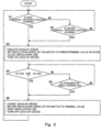
- control operations performed by the control device 6 will be explained in reference to a flow chart shown in Fig. 3 .
- the control device 6 determines whether or not a first downhill traveling condition is satisfied (Step S1).
- the first downhill traveling condition is a condition in which: the actual revolution speed N of the engine 21 detected by the revolution speed meter 61 is a first set revolution speed N1 (for example, 2,000 to 2,400 rpm) or more; and a load factor of the engine 21 is a predetermined rate R (for example, 5 to 20%) or less.
- the load factor of the engine 21 can be calculated from, for example, the amount of fuel injected to the engine 21.
- Step S1 When the first downhill traveling condition is satisfied (YES in Step S1), the process proceeds to Step S3. When the first downhill traveling condition is not satisfied (NO in Step S1), the process proceeds to Step S2.
- Step S2 the control device 6 determines whether or not a second downhill traveling condition is satisfied.
- the second downhill traveling condition is a condition in which the actual vehicle speed S detected by the vehicle speed meter 62 is not less than an allowable vehicle speed SL of the vehicle speed mode selected with the vehicle speed mode selector 73.
- the allowable vehicle speed SL can be calculated from the speed ratio of the transmission 23, which ratio is determined for each vehicle speed mode, and the first set revolution speed.
- Step S2 When the second downhill traveling condition is satisfied (YES in Step S2), the process proceeds to Step S3. When the second downhill traveling condition is not satisfied (NO in Step S2), the process returns to Step S1. In the present embodiment, whether or not the first downhill traveling condition is satisfied is first determined, and whether or not the second downhill traveling condition is satisfied is then determined. However, whether or not the second downhill traveling condition is satisfied may be first determined, and whether or not the first downhill traveling condition is satisfied may be then determined. To be specific, the process is only required to be set to proceed to Step 3 when any one of the first downhill traveling condition and the second downhill traveling condition is satisfied. Or, the process may adopt only one of Steps S1 and S2. When only the first downhill traveling condition is adopted, the vehicle speed mode selector 73 may not be provided, and the speed ratios of the transmission 23 may be automatically switched.
- Step S3 the control device 6 performs an operation of increasing the load of the engine 21, in other words, an operation of causing braking force to act on the engine 21.
- the control device 6 performs four operations 1 to 4 below.
- Operation 1 Control the exhaust adjustment mechanism 54 such that the exhaust adjustment mechanism 54 executes exhaust brake (i.e., reduces the flow rate of the exhaust from the engine 21 to increase the load of the engine 21)
- Operation 2 Control the fan circuit 38 such that the revolution speed of the fan motor 39 becomes a predetermined value (for example, twice a normal revolution speed) or more.
- Operation 3 Control the on-off valve 43 such that the on-off valve 43 closes the circulation line 41.
- Operation 4 Control the lock-up device 26 such that the lock-up device 26 fixes the output shaft of the torque converter 22 to the input shaft of the torque converter 22.
- control device 6 is only required to perform at least Operation 1. In addition to Operation 1, the control device 6 may perform one or two out of Operations 2 to 4 or may perform none of Operations 2 to 4.
- the control device 6 determines whether or not the actual revolution speed N of the engine 21 is less than a second set revolution speed N2, and the actual vehicle speed S is less than a set vehicle speed Sd (Step S4).
- the second set revolution speed N2 may be equal to the first set revolution speed N1 or may be less than the first set revolution speed N1.
- the set vehicle speed Sd may be equal to the allowable vehicle speed SL or may be less than the allowable vehicle speed SL. If YES in Step S4, the process proceeds to Step S6. If NO in Step S4, the process proceeds to Step S5.
- Step S5 the control device 6 determines whether or not the accelerator pedal 71 is stepped on. If YES in Step S5, the process proceeds to Step S6. If NO in Step S5, the process returns to Step S4.
- Step S5 is performed after Step S4. However, Step S4 may be performed after Step S5. Or, the process may adopt only one of Steps S4 and S5.
- Step S6 the control device 6 stops performing all Operations 1 to 4. Specifically, the control device 6 (1) controls the exhaust adjustment mechanism 54 such that the exhaust adjustment mechanism 54 cancels the exhaust brake, (2) controls the fan circuit 38 such that the revolution speed of the fan motor 39 returns to an original speed, (3) controls the on-off valve 43 such that the on-off valve 43 opens the circulation line 41, and (4) controls the lock-up device 26 such that the lock-up device 26 unfixes the output shaft of the transmission 23 from the input shaft of the transmission 23. Then, the process returns to Step S1.
- the control device 6 (1) controls the exhaust adjustment mechanism 54 such that the exhaust adjustment mechanism 54 cancels the exhaust brake, (2) controls the fan circuit 38 such that the revolution speed of the fan motor 39 returns to an original speed, (3) controls the on-off valve 43 such that the on-off valve 43 opens the circulation line 41, and (4) controls the lock-up device 26 such that the lock-up device 26 unfixes the output shaft of the transmission 23 from the input shaft of the transmission 23. Then, the process returns to Step S1.
- the exhaust brake is automatically executed during the downhill traveling based on the determinations in Steps S1 and S2. Therefore, the engine revolution speed can be prevented from becoming too high by utilizing the exhaust brake without frequently switching the on and off of the exhaust brake.
- braking force other than braking force of a foot brake acts during the downhill traveling, the frequency of use of the foot brake can be reduced.
- the exhaust brake can be canceled at an appropriate timing based on the determinations in Steps S4 and S5.
- the revolution speed of the fan motor 39 is set to the predetermined value or more, the operating oil flows through the relief valve 46 by closing the circulation line 41, and engine brake acts by turning on the lock-up device 26.
- the revolution speed of the fan motor 39 is 500 rpm during a normal time in which the temperatures of the operating oil and the cooling water are low
- the revolution speed of the fan motor 39 during the downhill traveling is set to about 1,500 rpm.
- the revolution speed of the engine 21 can be reduced by about 300 rpm. It should be noted that only one or two out of Operations 2 to 4 may be performed in accordance with a situation.
- the present invention is applicable to construction machines, such as hydraulic excavators (including crawlers), which are not wheel traveling type vehicles.
- traveling of the construction machine may be performed by hydraulic motors to which the operating oil is supplied from the main pump 31.
- the exhaust adjustment mechanism 54 may be any mechanism as long as it can adjust the flow rate of the exhaust from the engine 21.
- the exhaust adjustment mechanism 54 may be a butterfly valve provided on an exhaust passage extending from the engine 21.
Description
- The present invention relates to a construction machine including an engine driving at least one hydraulic pump.
- In a construction machine including a hydraulic actuator, a hydraulic pump configured to supply operating oil to the hydraulic actuator is driven by an engine (see
PTL 1, for example). According to such construction machine, if an engine revolution speed becomes too high, devices such as the hydraulic pump may be damaged. - Furthermore, PTL 2 and PTL 3 respectively discloses further alternatives of an engine brake system.
-
- PTL 1:
U.S. Patent No. 7849688 , Specification - PTL 2:
US 6 652 414 B1 - PTL 3:
US 2010/168976 A1 - For example, to prevent the engine revolution speed from becoming too high, there is a method of, when the engine revolution speed becomes a threshold or more, reducing a flow rate of exhaust from the engine to increase a load of the engine (i.e., so-called exhaust brake).
- When the exhaust brake is automatically executed by comparing the engine revolution speed with the threshold, on and off of the exhaust brake are switched frequently. Such frequent switching of the on and off of the exhaust brake is not preferable from the viewpoint of durability of engine parts (such as a turbocharger).
- An object of the present invention is to provide a construction machine capable of preventing an engine revolution speed from becoming too high by utilizing exhaust brake without frequently switching on and off of the exhaust brake.
- To solve the above problems, the inventors of the present invention have diligently studied, and as a result, have focused on the fact that: during downhill traveling, a high revolution speed (high vehicle speed) is maintained, and a state where an engine does not use energy for traveling continues. Based on this, the inventors of the present invention have thought of an idea of automatically executing exhaust brake during the downhill traveling. With this, the inventors of the present invention have thought that frequent switching of the on and off of the exhaust brake can be prevented. The present invention was made from such viewpoint.
- To be specific, to solve the above problems, a construction machine of the invention having the features of
independent claim 1 is provided. Preferred embodiments are described in the dependent claim. In particular, the present invention provides a construction machine including: an engine driving at least one hydraulic pump configured to supply operating oil to a hydraulic actuator; an exhaust adjustment mechanism adjusting a flow rate of exhaust from the engine; and a control device controlling the exhaust adjustment mechanism, wherein: the control device determines whether or not a first downhill traveling condition and/or a second downhill traveling condition are/is satisfied, the first downhill traveling condition being a condition in which an actual revolution speed of engine is a set revolution speed or more and a load factor of the engine is a set rate or less, the second downhill traveling condition being a condition in which when the engine is coupled to a wheel through a transmission, an actual vehicle speed is not less than an allowable vehicle speed of a vehicle speed mode selected by an operator; and the control device controls the exhaust adjustment mechanism such that the exhaust adjustment mechanism executes exhaust brake when at least one of the first downhill traveling condition and the second downhill traveling condition is satisfied. - According to the above configuration, since the exhaust brake is automatically executed during downhill traveling, the engine revolution speed can be prevented from becoming too high by utilizing the exhaust brake without frequently switching on and off of the exhaust brake. In addition, since braking force other than braking force of a foot brake acts during the downhill traveling, the frequency of use of the foot brake can be reduced.
- For example, the vehicle speed may be a revolution speed of an output shaft of the transmission.
- The control device may control the exhaust adjustment mechanism such that the exhaust adjustment mechanism cancels the exhaust brake when the actual revolution speed of the engine is less than a secondary set revolution speed that is not more than the set revolution speed, and the actual vehicle speed is less than a set vehicle speed that is not more than the allowable vehicle speed, or when an accelerator pedal is stepped on. According to this configuration, the exhaust brake can be canceled at an appropriate timing.
- The construction machine is configured such that: the at least one hydraulic pump includes a fan pump; the construction machine further includes a fan motor supplied with the operating oil from the fan pump and configured to cool the engine and a fan circuit configured to set a revolution speed of the fan motor; and when at least one of the first downhill traveling condition and the second downhill traveling condition is satisfied, the control device controls the fan circuit such that the revolution speed of the fan motor becomes a predetermined value or more. According to this configuration, even when only the exhaust brake does not suffice, such as when acceleration during the downhill traveling is large, the engine revolution speed can be prevented from becoming too high.
- The construction machine is configured such that: the at least one hydraulic pump includes a main pump; the construction machine further includes a circulation line extending from the main pump through a cargo circuit to a tank, a release line branching from the circulation line at a position upstream of the cargo circuit, the release line extending to the tank, a relief valve being provided on the release line, and an on-off valve provided on the circulation line at a position downstream of a branch point of the release line; and the control device controls the on-off valve such that the on-off valve closes the circulation line when at least one of the first downhill traveling condition and the second downhill traveling condition is satisfied. According to this configuration, even when only the exhaust brake does not suffice, such as when acceleration during the downhill traveling is large, the engine revolution speed can be prevented from becoming too high.
- The construction machine may further include: a wheel coupled to the engine through the transmission and a torque converter that is a fluid coupling; and a lock-up device configured to switch fixing and unfixing between an output shaft of the torque converter and an input shaft of the torque converter, wherein the control device may control the lock-up device such that the lock-up device fixes the output shaft of the torque converter to the input shaft of the torque converter when at least one of the first downhill traveling condition and the second downhill traveling condition is satisfied. According to this configuration, even when only the exhaust brake does not suffice, such as when acceleration during the downhill traveling is large, the engine revolution speed can be prevented from becoming too high.
- For example, the above construction machine may further include a turbocharger including a compressor and a turbine, the compressor and the turbine being connected to the engine, wherein: the turbine may be a variable nozzle turbine; and the exhaust adjustment mechanism may change an opening degree of a nozzle of the turbine to adjust a flow rate of exhaust from the engine.
- According to the present invention, the engine revolution speed can be prevented from becoming too high by utilizing the exhaust brake without frequently switching the on and off of the exhaust brake.
-
-
Fig. 1 is a diagram schematically showing a schematic configuration of a construction machine according to one embodiment of the present invention. -
Fig. 2 is a side view of the construction machine shown inFig. 1 . -
Fig. 3 is a flow chart of control operations performed by a control device. -
Fig. 2 shows aconstruction machine 1 according to one embodiment of the present invention.Fig. 1 schematically shows a schematic configuration of theconstruction machine 1. Theconstruction machine 1 shown inFig. 2 is a wheel loader that is one of wheel traveling type industrial vehicles. It should be noted that the present invention is also applicable to other industrial vehicles such as shovel loaders, forklifts, and truck cranes. - As shown in
Fig. 2 , theconstruction machine 1 includes afront vehicle body 11 and arear vehicle body 12 which are coupled to each other so as to be swingable in a horizontal direction. Afront wheel 16 is attached to thefront vehicle body 11, and arear wheel 17 is attached to therear vehicle body 12. A pair of left and right steering cylinders (hydraulic actuators) 34 for changing a traveling direction is provided between thefront vehicle body 11 and therear vehicle body 12. - The
rear vehicle body 12 is provided with a driver'scab 13 and anengine room 18. Anengine 21, aradiator 19, and a fan motor (hydraulic actuator) 39 are arranged in theengine room 18, and theradiator 19 and thefan motor 39 cool theengine 21. Aboom 14 is coupled to thefront vehicle body 11 so as to be swingable in a vertical direction, and abucket 15 is coupled to a tip end of theboom 14 so as to be swingable in the vertical direction. Thefront vehicle body 11 is provided with a pair of left and right boom cylinders (hydraulic actuators) 36 configured to actuate theboom 14 and a bucket cylinder (hydraulic actuator) 37 configured to actuate thebucket 15. - As shown in
Figs. 1 and2 , theengine 21 is coupled to thewheels torque converter 22, atransmission 23, andaxles transmission 23 can change a speed ratio between input and output shafts thereof and can switch a rotational direction of the output shaft between the same direction as the input shaft and an opposite direction to the input shaft for switching between forward traveling and backward traveling of the vehicle. - The
torque converter 22 is a fluid coupling. In the present embodiment, there is provided a lock-updevice 26 configured to switch fixing and unfixing between an output shaft of thetorque converter 22 and an input shaft of thetorque converter 22. - A
main pump 31 and afan pump 32 are hydraulic pumps and coupled to thetorque converter 22. To be specific, themain pump 31 and thefan pump 32 are driven by theengine 21. Thefan pump 32 may be directly coupled to theengine 21. - The
main pump 31 supplies operating oil through acargo circuit 35 to theboom cylinders 36 and thebucket cylinder 37 and also supplies the operating oil through asteering circuit 33 to thesteering cylinders 34. To simplifyFig. 1 , the pair ofboom cylinders 36 and thebucket cylinder 37 are shown by one cylinder sign, and the pair ofsteering cylinders 34 are also shown by one cylinder sign. - A
circulation line 41 extends from themain pump 31 through thecargo circuit 35 to atank 40. To be specific, thecirculation line 41 constitutes a center bypass line of thecargo circuit 35. Abranch line 44 branches from thecirculation line 41 at a position upstream of thecargo circuit 35. Thebranch line 44 is connected to thesteering circuit 33. - The
cargo circuit 35 includes: a boom control valve (not shown) configured to control supplying and discharging the operating oil to and from theboom cylinders 36; and a bucket control valve (not shown) configured to control supplying and discharging the operating oil to and from thebucket cylinder 37. For example, an operating valve including an operating lever outputs pilot pressure to each of the control valves. Thesteering circuit 33 includes a steering valve (not shown) configured to control supplying and discharging the operating oil to and from thesteering cylinders 34. For example, a steerage signal output device such as an orbit roll (trademark) outputs a steerage signal (pilot stream) to the steering valve. - Further, a
release line 45 branches from thecirculation line 41 at a position upstream of thecargo circuit 35. Therelease line 45 extends to thetank 40. Arelief valve 46 is provided on therelease line 45. - An on-off
valve 43 is provided on thecirculation line 41 at a position downstream of a branch point of therelease line 45. The on-offvalve 43 switches to open or close thecirculation line 41. In the present embodiment, the on-offvalve 43 is arranged upstream of thecargo circuit 35. However, the on-offvalve 43 may be arranged downstream of thecargo circuit 35. - The
fan pump 32 supplies the operating oil through afan circuit 38 to thefan motor 39. Thefan circuit 38 sets a revolution speed of thefan motor 39 and, for example, includes: a pressure reducing valve introducing arbitrary pressure to a flow-out line of thefan motor 39; and an electromagnetic proportional valve outputting pilot pressure to the pressure reducing valve. - The
engine 21 is connected to acompressor 52 andturbine 53 of aturbocharger 51. In the present embodiment, theturbine 53 is a variable nozzle turbine, and an opening degree of a nozzle of theturbine 53 is changed by anexhaust adjustment mechanism 54. To be specific, theexhaust adjustment mechanism 54 adjusts a flow rate of exhaust from theengine 21. - The
exhaust adjustment mechanism 54 is controlled by acontrol device 6. Thecontrol device 6 is connected to: arevolution speed meter 61 configured to detect an actual revolution speed N of theengine 21; avehicle speed meter 62 configured to detect an actual vehicle speed S of theconstruction machine 1; apedal sensor 72 configured to detect a step-on amount of anaccelerator pedal 71; and a vehiclespeed mode selector 73. In the present embodiment, thevehicle speed meter 62 is a revolution speed meter configured to detect a revolution speed of the output shaft of thetransmission 23 as the vehicle speed. - The vehicle
speed mode selector 73 is arranged in the driver'scab 13 and accepts a selection made from a plurality of vehicle speed modes by an operator. In the present embodiment, the vehicle speed modes indicate the speed ratios of thetransmission 23 by a plurality of stages (such as first to fifth stages). However, the vehicle speed modes do not necessarily have to indicate the speed ratios of thetransmission 23 by the plurality of stages. For example, the vehicle speed modes may include a manual mode of manually switching the speed ratios of thetransmission 23 and an automatic mode of automatically switching the speed ratios of thetransmission 23 or may be a plurality of driving modes in which respective different upper limits of the engine revolution speed are determined. - The
control device 6 may be constituted by an engine control device controlling engine related devices and a vehicle body controller controlling hydraulic devices or may be constituted by one unit collectively controlling all the devices. - Hereinafter, control operations performed by the
control device 6 will be explained in reference to a flow chart shown inFig. 3 . - First, the
control device 6 determines whether or not a first downhill traveling condition is satisfied (Step S1). The first downhill traveling condition is a condition in which: the actual revolution speed N of theengine 21 detected by therevolution speed meter 61 is a first set revolution speed N1 (for example, 2,000 to 2,400 rpm) or more; and a load factor of theengine 21 is a predetermined rate R (for example, 5 to 20%) or less. The load factor of theengine 21 can be calculated from, for example, the amount of fuel injected to theengine 21. - When the first downhill traveling condition is satisfied (YES in Step S1), the process proceeds to Step S3. When the first downhill traveling condition is not satisfied (NO in Step S1), the process proceeds to Step S2.
- In Step S2, the
control device 6 determines whether or not a second downhill traveling condition is satisfied. The second downhill traveling condition is a condition in which the actual vehicle speed S detected by thevehicle speed meter 62 is not less than an allowable vehicle speed SL of the vehicle speed mode selected with the vehiclespeed mode selector 73. For example, the allowable vehicle speed SL can be calculated from the speed ratio of thetransmission 23, which ratio is determined for each vehicle speed mode, and the first set revolution speed. - When the second downhill traveling condition is satisfied (YES in Step S2), the process proceeds to Step S3. When the second downhill traveling condition is not satisfied (NO in Step S2), the process returns to Step S1. In the present embodiment, whether or not the first downhill traveling condition is satisfied is first determined, and whether or not the second downhill traveling condition is satisfied is then determined. However, whether or not the second downhill traveling condition is satisfied may be first determined, and whether or not the first downhill traveling condition is satisfied may be then determined. To be specific, the process is only required to be set to proceed to Step 3 when any one of the first downhill traveling condition and the second downhill traveling condition is satisfied. Or, the process may adopt only one of Steps S1 and S2. When only the first downhill traveling condition is adopted, the vehicle
speed mode selector 73 may not be provided, and the speed ratios of thetransmission 23 may be automatically switched. - In Step S3, the
control device 6 performs an operation of increasing the load of theengine 21, in other words, an operation of causing braking force to act on theengine 21. In the present embodiment, thecontrol device 6 performs fouroperations 1 to 4 below. - Operation 1: Control the
exhaust adjustment mechanism 54 such that theexhaust adjustment mechanism 54 executes exhaust brake (i.e., reduces the flow rate of the exhaust from theengine 21 to increase the load of the engine 21) - Operation 2: Control the
fan circuit 38 such that the revolution speed of thefan motor 39 becomes a predetermined value (for example, twice a normal revolution speed) or more. - Operation 3: Control the on-off
valve 43 such that the on-offvalve 43 closes thecirculation line 41. - Operation 4: Control the lock-up
device 26 such that the lock-updevice 26 fixes the output shaft of thetorque converter 22 to the input shaft of thetorque converter 22. - It should be noted that the
control device 6 is only required to perform atleast Operation 1. In addition toOperation 1, thecontrol device 6 may perform one or two out of Operations 2 to 4 or may perform none of Operations 2 to 4. - After that, until a condition for canceling the operation of increasing the load is satisfied, the
control device 6 keeps on performingOperations 1 to 4. In the present embodiment, first, thecontrol device 6 determines whether or not the actual revolution speed N of theengine 21 is less than a second set revolution speed N2, and the actual vehicle speed S is less than a set vehicle speed Sd (Step S4). The second set revolution speed N2 may be equal to the first set revolution speed N1 or may be less than the first set revolution speed N1. The set vehicle speed Sd may be equal to the allowable vehicle speed SL or may be less than the allowable vehicle speed SL. If YES in Step S4, the process proceeds to Step S6. If NO in Step S4, the process proceeds to Step S5. - In Step S5, the
control device 6 determines whether or not theaccelerator pedal 71 is stepped on. If YES in Step S5, the process proceeds to Step S6. If NO in Step S5, the process returns to Step S4. In the present embodiment, Step S5 is performed after Step S4. However, Step S4 may be performed after Step S5. Or, the process may adopt only one of Steps S4 and S5. - In Step S6, the
control device 6 stops performing allOperations 1 to 4. Specifically, the control device 6 (1) controls theexhaust adjustment mechanism 54 such that theexhaust adjustment mechanism 54 cancels the exhaust brake, (2) controls thefan circuit 38 such that the revolution speed of thefan motor 39 returns to an original speed, (3) controls the on-offvalve 43 such that the on-offvalve 43 opens thecirculation line 41, and (4) controls the lock-updevice 26 such that the lock-updevice 26 unfixes the output shaft of thetransmission 23 from the input shaft of thetransmission 23. Then, the process returns to Step S1. - As explained above, according to the
construction machine 1 of the present embodiment, the exhaust brake is automatically executed during the downhill traveling based on the determinations in Steps S1 and S2. Therefore, the engine revolution speed can be prevented from becoming too high by utilizing the exhaust brake without frequently switching the on and off of the exhaust brake. In addition, since braking force other than braking force of a foot brake acts during the downhill traveling, the frequency of use of the foot brake can be reduced. - Further, in the present embodiment, the exhaust brake can be canceled at an appropriate timing based on the determinations in Steps S4 and S5.
- Furthermore, in the present embodiment, during the downhill traveling, in addition to the execution of the exhaust brake, the revolution speed of the
fan motor 39 is set to the predetermined value or more, the operating oil flows through therelief valve 46 by closing thecirculation line 41, and engine brake acts by turning on the lock-updevice 26. With this, even when only the exhaust brake does not suffice, such as when acceleration during the downhill traveling is large (for example, when the angle of a slope is large or when the downhill traveling is performed while holding a burden by the bucket 15), the engine revolution speed can be prevented from becoming too high. For example, when the revolution speed of thefan motor 39 is 500 rpm during a normal time in which the temperatures of the operating oil and the cooling water are low, the revolution speed of thefan motor 39 during the downhill traveling is set to about 1,500 rpm. With this, the revolution speed of theengine 21 can be reduced by about 300 rpm. It should be noted that only one or two out of Operations 2 to 4 may be performed in accordance with a situation. - The present invention is not limited to the above embodiment, and various modifications may be made within the scope of the present invention.
- For example, the present invention is applicable to construction machines, such as hydraulic excavators (including crawlers), which are not wheel traveling type vehicles. To be specific, traveling of the construction machine may be performed by hydraulic motors to which the operating oil is supplied from the
main pump 31. - The
exhaust adjustment mechanism 54 may be any mechanism as long as it can adjust the flow rate of the exhaust from theengine 21. For example, when theturbine 53 of theturbocharger 51 is not the variable nozzle turbine or when theturbocharger 51 is not provided, theexhaust adjustment mechanism 54 may be a butterfly valve provided on an exhaust passage extending from theengine 21. -
- 1
- construction machine
- 16, 17
- wheel
- 21
- engine
- 22
- torque converter
- 23
- transmission
- 26
- lock-up device
- 31
- main pump (hydraulic pump)
- 32
- fan pump (hydraulic pump)
- 34
- steering cylinder (hydraulic actuator)
- 35
- cargo circuit
- 36
- boom cylinder (hydraulic actuator)
- 37
- bucket cylinder (hydraulic actuator)
- 38
- fan circuit
- 39
- fan motor (hydraulic actuator)
- 40
- tank
- 41
- circulation line
- 43
- on-off valve
- 45
- release line
- 46
- relief valve
- 51
- turbocharger
- 52
- compressor
- 53
- turbine
- 54
- exhaust adjustment mechanism
- 6
- control device
Claims (5)
- A construction machine comprising:an engine (21) driving hydraulic pumps configured to supply operating oil to hydraulic actuators,a wheel (16, 17) coupled to the engine (21) through a transmission (23),a main pump (31) serving as the hydraulic pump that supplies the operating oil to a boom cylinder (36) that actuates a boom (14), a bucket cylinder (37) that actuates a bucket (15), and a steering cylinder (34) that actuates a steering,a fan pump (32) serving as the hydraulic pump that supplies the operating oil to a fan motor (39) which is configured to cool the engine (21), anda fan circuit (38) configured to set a revolution speed of the fan motor (39), wherein the main pump (31) supplies the operating oil to the boom cylinder (36) and the bucket cylinder (37) through a cargo circuit (35),wherein the construction machine is characterized by further comprising:a circulation line (41) extending from the main pump (31) through a cargo circuit (35) to a tank (40),a release line (45) branching from the circulation line (41) at a position upstream of the cargo circuit (35), the release line (45) extending to the tank (40), a relief valve (46) being provided on the release line (45), andan on-off valve (43) provided on the circulation line (41) at a position downstream of a branch point of the release line (45),a steering circuit (33) branching from the circulation line (41) at a position upstream of the on-off valve (43) and connected to the steering cylinder (34),an exhaust adjustment mechanism (54) adjusting a flow rate of exhaust from the engine (21), anda control device (6) controlling the exhaust adjustment mechanism (54), wherein:the control device (6) determines whether or not a first downhill traveling condition or a second downhill traveling condition is satisfied, the first downhill traveling condition being a condition in which an actual revolution speed of engine is a set revolution speed or more and a load factor of the engine is a set rate or less, the second downhill traveling condition being a condition in which when the engine (21) is coupled to the wheel (16, 17) through the transmission (23), an actual vehicle speed is not less than an allowable vehicle speed of a vehicle speed mode selected by an operator, andwhen one of the first downhill traveling condition and the second downhill traveling condition is satisfied, the control device (6) controls the exhaust adjustment mechanism (54) such that the exhaust adjustment mechanism (54) executes exhaust brake, controls the fan circuit (38) such that the revolution speed of the fan motor (39) becomes a predetermined value or more, and controls the on-off valve (43) such that the on-off valve (43) closes the circulation line (41).
- The construction machine (1) according to claim 1, wherein the vehicle speed is a revolution speed of an output shaft of the transmission.
- The construction machine according to claim 1 or 2, wherein the control device (6) controls the exhaust adjustment mechanism (54) such that the exhaust adjustment mechanism (54) cancels the exhaust brake, controls the fan circuit (38) such that the revolution speed of the fan motor (39) becomes a revolution speed used before the revolution speed of the fan motor (39) is set to the predetermined value or more, and controls the on-off valve (43) such that the on-off valve (43) opens the circulation line (41), when the actual revolution speed of the engine is less than a secondary set revolution speed that is not more than the set revolution speed, and the actual vehicle speed is less than a set vehicle speed that is not more than the allowable vehicle speed in a case where the engine (21) is coupled to the wheel (16, 17) through the transmission (23), or when an accelerator pedal is stepped on.
- The construction machine (1) according to any one of claims 1 to 3, further comprising:a torque converter (22) that is a fluid coupling and is interposed between the engine (21) and the transmission (23), anda lock-up device (26) configured to switch fixing and unfixing between an output shaft of the torque converter (22) and an input shaft of the torque converter (22), whereinthe control device (6) controls the lock-up device (26) such that the lock-up device (26) fixes the output shaft of the torque converter (22) to the input shaft of the torque converter when at least one of the first downhill traveling condition and the second downhill traveling condition is satisfied.
- The construction machine (1) according to any one of claims 1 to 4, further comprising a turbocharger (51) including a compressor (52) and a turbine (53), the compressor (52) and the turbine (53) being connected to the engine (21), wherein:the turbine (53) is a variable nozzle turbine, andthe exhaust adjustment mechanism (54) changes an opening degree of a nozzle of the turbine (53) to adjust a flow rate of exhaust from the engine.
Applications Claiming Priority (2)
| Application Number | Priority Date | Filing Date | Title |
|---|---|---|---|
| JP2015188117A JP6343268B2 (en) | 2015-09-25 | 2015-09-25 | Construction machinery |
| PCT/JP2016/004320 WO2017051540A1 (en) | 2015-09-25 | 2016-09-23 | Construction machine |
Publications (3)
| Publication Number | Publication Date |
|---|---|
| EP3354886A1 EP3354886A1 (en) | 2018-08-01 |
| EP3354886A4 EP3354886A4 (en) | 2019-05-29 |
| EP3354886B1 true EP3354886B1 (en) | 2023-06-21 |
Family
ID=58385980
Family Applications (1)
| Application Number | Title | Priority Date | Filing Date |
|---|---|---|---|
| EP16848331.1A Active EP3354886B1 (en) | 2015-09-25 | 2016-09-23 | Construction machine |
Country Status (5)
| Country | Link |
|---|---|
| US (1) | US11046314B2 (en) |
| EP (1) | EP3354886B1 (en) |
| JP (1) | JP6343268B2 (en) |
| CN (1) | CN108138669B (en) |
| WO (1) | WO2017051540A1 (en) |
Families Citing this family (2)
| Publication number | Priority date | Publication date | Assignee | Title |
|---|---|---|---|---|
| US11225899B2 (en) * | 2019-02-28 | 2022-01-18 | Cummins Inc. | Supplemental engine braking system |
| CN113027616B (en) * | 2021-03-25 | 2023-05-23 | 潍柴动力股份有限公司 | Engine exhaust brake control method, engine exhaust brake control device, vehicle brake equipment and medium |
Citations (1)
| Publication number | Priority date | Publication date | Assignee | Title |
|---|---|---|---|---|
| US20140209061A1 (en) * | 2013-01-29 | 2014-07-31 | Navistar Defense Engineering, Llc | Engine brake improvement |
Family Cites Families (22)
| Publication number | Priority date | Publication date | Assignee | Title |
|---|---|---|---|---|
| US3719888A (en) * | 1971-05-26 | 1973-03-06 | Pentron Industries | Predetermined speed detector for digital tachometer |
| US4740898A (en) * | 1986-07-17 | 1988-04-26 | Deere & Company | Automatic engine/transmission control system |
| JP2974440B2 (en) * | 1991-03-22 | 1999-11-10 | 株式会社日立製作所 | Automotive integrated control device |
| JPH05319248A (en) * | 1992-05-26 | 1993-12-03 | Kobe Steel Ltd | Auxiliary brake device of vehicle |
| JPH07174219A (en) * | 1993-12-20 | 1995-07-11 | Hitachi Ltd | Transmission for vehicle |
| US5487005A (en) * | 1994-02-07 | 1996-01-23 | Eaton Corporation | Method/system for determination of gross combined weight of vehicles equipped with electronic data links |
| JP3186442B2 (en) * | 1994-07-13 | 2001-07-11 | トヨタ自動車株式会社 | Slip control device for vehicle lock-up clutch |
| JP3201218B2 (en) * | 1995-04-19 | 2001-08-20 | 三菱自動車工業株式会社 | Auto cruise control method |
| JP3699781B2 (en) * | 1996-07-04 | 2005-09-28 | 三菱ふそうトラック・バス株式会社 | Engine auxiliary brake device |
| JP3628498B2 (en) * | 1997-10-17 | 2005-03-09 | コベルコクレーン株式会社 | Wheel crane transmission control method and control device therefor |
| WO2000005490A1 (en) * | 1998-07-23 | 2000-02-03 | Sauer Inc. | Hydraulic fan drive system having a non-dedicated flow source |
| KR100353991B1 (en) * | 1999-12-24 | 2002-09-26 | 현대자동차주식회사 | Method for controlling diesel engine for vehicles |
| US6283091B1 (en) * | 2000-01-14 | 2001-09-04 | Mack Trucks, Inc. | Method and apparatus for controlling nozzle temperature during engine braking |
| US6652414B1 (en) * | 2001-11-26 | 2003-11-25 | Banks, Iii Gale C. | Vehicle engine brake and control system |
| US7849688B2 (en) | 2006-12-21 | 2010-12-14 | Caterpillar Inc | Method and apparatus for retarding an engine |
| US8738248B2 (en) * | 2008-10-21 | 2014-05-27 | Allison Transmission, Inc. | System for controlling vehicle overspeeding via control of one or more exhaust brake devices |
| US20100307465A1 (en) * | 2009-06-03 | 2010-12-09 | Ross George Haldeman | Infinitely variable, computer-controlled, positive pressure, electrically driven supercharger to increase fuel economy and performance |
| JP5156693B2 (en) * | 2009-06-17 | 2013-03-06 | 日立建機株式会社 | Industrial vehicle engine speed control device |
| ES2537702T3 (en) * | 2012-06-07 | 2015-06-11 | Daf Trucks N.V. | Control of a compression release brake |
| CN102889138A (en) * | 2012-09-21 | 2013-01-23 | 三一重工股份有限公司 | Engine exhaust brake control device and method and engineering vehicle |
| SE539194C2 (en) | 2013-04-30 | 2017-05-09 | Scania Cv Ab | Procedure and system for control of turbocharged engine during gearing |
| CN104533647A (en) * | 2014-12-22 | 2015-04-22 | 潍柴动力股份有限公司 | Method and device for controlling engine |
-
2015
- 2015-09-25 JP JP2015188117A patent/JP6343268B2/en active Active
-
2016
- 2016-09-23 US US15/762,920 patent/US11046314B2/en active Active
- 2016-09-23 WO PCT/JP2016/004320 patent/WO2017051540A1/en active Application Filing
- 2016-09-23 CN CN201680055853.2A patent/CN108138669B/en active Active
- 2016-09-23 EP EP16848331.1A patent/EP3354886B1/en active Active
Patent Citations (1)
| Publication number | Priority date | Publication date | Assignee | Title |
|---|---|---|---|---|
| US20140209061A1 (en) * | 2013-01-29 | 2014-07-31 | Navistar Defense Engineering, Llc | Engine brake improvement |
Also Published As
| Publication number | Publication date |
|---|---|
| US11046314B2 (en) | 2021-06-29 |
| CN108138669B (en) | 2021-09-21 |
| JP6343268B2 (en) | 2018-06-13 |
| WO2017051540A1 (en) | 2017-03-30 |
| EP3354886A4 (en) | 2019-05-29 |
| CN108138669A (en) | 2018-06-08 |
| US20180265086A1 (en) | 2018-09-20 |
| EP3354886A1 (en) | 2018-08-01 |
| JP2017061895A (en) | 2017-03-30 |
Similar Documents
| Publication | Publication Date | Title |
|---|---|---|
| KR101439305B1 (en) | Hydraulic pressure supply device for industrial vehicle | |
| CN100526623C (en) | Control device for traveling working vehicle | |
| EP2444637B1 (en) | Working vehicle control apparatus | |
| EP2538088B1 (en) | Motor control device for construction machinery | |
| JP5192601B1 (en) | Work vehicle and control method of work vehicle | |
| WO2016051815A1 (en) | Work machine hydraulic system and work machine | |
| US20160319848A1 (en) | Hydraulic Drive System | |
| US20060191732A1 (en) | Work machine hydraulics control system | |
| EP2589822B1 (en) | Control device for a hydraulic pump of construction machinery | |
| US10017918B2 (en) | Working machine | |
| CN104755770A (en) | Work machine | |
| CN104947734A (en) | Hydraulic system for working machine | |
| CN103946577A (en) | Clutch control device for work vehicle | |
| EP3354886B1 (en) | Construction machine | |
| EP3009689A1 (en) | Hydraulic system of a vehicle | |
| JPH11336136A (en) | Engine revolution number control device for construction machine | |
| JP2005069203A (en) | Cooling device of industrial vehicle | |
| EP1610040B1 (en) | Hydraulic travel drive device and motor vehicle with hydraulic travel drive | |
| CN110099816B (en) | System for assisting in driving a trailer from an open tipping hydraulic circuit | |
| US8483917B2 (en) | Backhoe loader | |
| EP2261427A1 (en) | Hydraulic work vehicle | |
| WO2020202652A1 (en) | Wheeled work vehicle | |
| KR102246421B1 (en) | Construction machinery control system and construction machinery control method | |
| JP6535871B2 (en) | Industrial vehicles | |
| KR20180118637A (en) | Working vehicle |
Legal Events
| Date | Code | Title | Description |
|---|---|---|---|
| STAA | Information on the status of an ep patent application or granted ep patent |
Free format text: STATUS: THE INTERNATIONAL PUBLICATION HAS BEEN MADE |
|
| PUAI | Public reference made under article 153(3) epc to a published international application that has entered the european phase |
Free format text: ORIGINAL CODE: 0009012 |
|
| STAA | Information on the status of an ep patent application or granted ep patent |
Free format text: STATUS: REQUEST FOR EXAMINATION WAS MADE |
|
| 17P | Request for examination filed |
Effective date: 20180425 |
|
| AK | Designated contracting states |
Kind code of ref document: A1 Designated state(s): AL AT BE BG CH CY CZ DE DK EE ES FI FR GB GR HR HU IE IS IT LI LT LU LV MC MK MT NL NO PL PT RO RS SE SI SK SM TR |
|
| AX | Request for extension of the european patent |
Extension state: BA ME |
|
| DAV | Request for validation of the european patent (deleted) | ||
| DAX | Request for extension of the european patent (deleted) | ||
| A4 | Supplementary search report drawn up and despatched |
Effective date: 20190502 |
|
| RIC1 | Information provided on ipc code assigned before grant |
Ipc: F16H 61/14 20060101ALI20190425BHEP Ipc: B60W 10/06 20060101ALI20190425BHEP Ipc: B60W 10/02 20060101ALI20190425BHEP Ipc: F02D 9/06 20060101ALI20190425BHEP Ipc: B60W 10/04 20060101ALI20190425BHEP Ipc: F16H 59/66 20060101ALI20190425BHEP Ipc: B60W 30/188 20120101ALI20190425BHEP Ipc: F02D 45/00 20060101ALI20190425BHEP Ipc: F02D 29/04 20060101AFI20190425BHEP Ipc: F02B 37/12 20060101ALI20190425BHEP Ipc: F02B 37/24 20060101ALI20190425BHEP Ipc: F02D 29/00 20060101ALI20190425BHEP |
|
| RAP1 | Party data changed (applicant data changed or rights of an application transferred) |
Owner name: HITACHI CONSTRUCTION MACHINERY CO., LTD |
|
| STAA | Information on the status of an ep patent application or granted ep patent |
Free format text: STATUS: EXAMINATION IS IN PROGRESS |
|
| 17Q | First examination report despatched |
Effective date: 20210709 |
|
| STAA | Information on the status of an ep patent application or granted ep patent |
Free format text: STATUS: EXAMINATION IS IN PROGRESS |
|
| GRAP | Despatch of communication of intention to grant a patent |
Free format text: ORIGINAL CODE: EPIDOSNIGR1 |
|
| STAA | Information on the status of an ep patent application or granted ep patent |
Free format text: STATUS: GRANT OF PATENT IS INTENDED |
|
| INTG | Intention to grant announced |
Effective date: 20230404 |
|
| GRAS | Grant fee paid |
Free format text: ORIGINAL CODE: EPIDOSNIGR3 |
|
| GRAA | (expected) grant |
Free format text: ORIGINAL CODE: 0009210 |
|
| STAA | Information on the status of an ep patent application or granted ep patent |
Free format text: STATUS: THE PATENT HAS BEEN GRANTED |
|
| AK | Designated contracting states |
Kind code of ref document: B1 Designated state(s): AL AT BE BG CH CY CZ DE DK EE ES FI FR GB GR HR HU IE IS IT LI LT LU LV MC MK MT NL NO PL PT RO RS SE SI SK SM TR |
|
| REG | Reference to a national code |
Ref country code: CH Ref legal event code: EP |
|
| REG | Reference to a national code |
Ref country code: DE Ref legal event code: R096 Ref document number: 602016080516 Country of ref document: DE |
|
| REG | Reference to a national code |
Ref country code: AT Ref legal event code: REF Ref document number: 1581053 Country of ref document: AT Kind code of ref document: T Effective date: 20230715 |
|
| REG | Reference to a national code |
Ref country code: IE Ref legal event code: FG4D |
|
| REG | Reference to a national code |
Ref country code: LT Ref legal event code: MG9D |
|
| REG | Reference to a national code |
Ref country code: NL Ref legal event code: MP Effective date: 20230621 |
|
| PG25 | Lapsed in a contracting state [announced via postgrant information from national office to epo] |
Ref country code: SE Free format text: LAPSE BECAUSE OF FAILURE TO SUBMIT A TRANSLATION OF THE DESCRIPTION OR TO PAY THE FEE WITHIN THE PRESCRIBED TIME-LIMIT Effective date: 20230621 Ref country code: NO Free format text: LAPSE BECAUSE OF FAILURE TO SUBMIT A TRANSLATION OF THE DESCRIPTION OR TO PAY THE FEE WITHIN THE PRESCRIBED TIME-LIMIT Effective date: 20230921 |
|
| REG | Reference to a national code |
Ref country code: AT Ref legal event code: MK05 Ref document number: 1581053 Country of ref document: AT Kind code of ref document: T Effective date: 20230621 |
|
| PG25 | Lapsed in a contracting state [announced via postgrant information from national office to epo] |
Ref country code: RS Free format text: LAPSE BECAUSE OF FAILURE TO SUBMIT A TRANSLATION OF THE DESCRIPTION OR TO PAY THE FEE WITHIN THE PRESCRIBED TIME-LIMIT Effective date: 20230621 Ref country code: NL Free format text: LAPSE BECAUSE OF FAILURE TO SUBMIT A TRANSLATION OF THE DESCRIPTION OR TO PAY THE FEE WITHIN THE PRESCRIBED TIME-LIMIT Effective date: 20230621 Ref country code: LV Free format text: LAPSE BECAUSE OF FAILURE TO SUBMIT A TRANSLATION OF THE DESCRIPTION OR TO PAY THE FEE WITHIN THE PRESCRIBED TIME-LIMIT Effective date: 20230621 Ref country code: LT Free format text: LAPSE BECAUSE OF FAILURE TO SUBMIT A TRANSLATION OF THE DESCRIPTION OR TO PAY THE FEE WITHIN THE PRESCRIBED TIME-LIMIT Effective date: 20230621 Ref country code: HR Free format text: LAPSE BECAUSE OF FAILURE TO SUBMIT A TRANSLATION OF THE DESCRIPTION OR TO PAY THE FEE WITHIN THE PRESCRIBED TIME-LIMIT Effective date: 20230621 Ref country code: GR Free format text: LAPSE BECAUSE OF FAILURE TO SUBMIT A TRANSLATION OF THE DESCRIPTION OR TO PAY THE FEE WITHIN THE PRESCRIBED TIME-LIMIT Effective date: 20230922 |
|
| PGFP | Annual fee paid to national office [announced via postgrant information from national office to epo] |
Ref country code: DE Payment date: 20230930 Year of fee payment: 8 |
|
| PG25 | Lapsed in a contracting state [announced via postgrant information from national office to epo] |
Ref country code: FI Free format text: LAPSE BECAUSE OF FAILURE TO SUBMIT A TRANSLATION OF THE DESCRIPTION OR TO PAY THE FEE WITHIN THE PRESCRIBED TIME-LIMIT Effective date: 20230621 |
|
| PG25 | Lapsed in a contracting state [announced via postgrant information from national office to epo] |
Ref country code: SK Free format text: LAPSE BECAUSE OF FAILURE TO SUBMIT A TRANSLATION OF THE DESCRIPTION OR TO PAY THE FEE WITHIN THE PRESCRIBED TIME-LIMIT Effective date: 20230621 |
|
| PG25 | Lapsed in a contracting state [announced via postgrant information from national office to epo] |
Ref country code: ES Free format text: LAPSE BECAUSE OF FAILURE TO SUBMIT A TRANSLATION OF THE DESCRIPTION OR TO PAY THE FEE WITHIN THE PRESCRIBED TIME-LIMIT Effective date: 20230621 |
|
| PG25 | Lapsed in a contracting state [announced via postgrant information from national office to epo] |
Ref country code: IS Free format text: LAPSE BECAUSE OF FAILURE TO SUBMIT A TRANSLATION OF THE DESCRIPTION OR TO PAY THE FEE WITHIN THE PRESCRIBED TIME-LIMIT Effective date: 20231021 |
|
| PG25 | Lapsed in a contracting state [announced via postgrant information from national office to epo] |
Ref country code: SM Free format text: LAPSE BECAUSE OF FAILURE TO SUBMIT A TRANSLATION OF THE DESCRIPTION OR TO PAY THE FEE WITHIN THE PRESCRIBED TIME-LIMIT Effective date: 20230621 Ref country code: SK Free format text: LAPSE BECAUSE OF FAILURE TO SUBMIT A TRANSLATION OF THE DESCRIPTION OR TO PAY THE FEE WITHIN THE PRESCRIBED TIME-LIMIT Effective date: 20230621 Ref country code: RO Free format text: LAPSE BECAUSE OF FAILURE TO SUBMIT A TRANSLATION OF THE DESCRIPTION OR TO PAY THE FEE WITHIN THE PRESCRIBED TIME-LIMIT Effective date: 20230621 Ref country code: PT Free format text: LAPSE BECAUSE OF FAILURE TO SUBMIT A TRANSLATION OF THE DESCRIPTION OR TO PAY THE FEE WITHIN THE PRESCRIBED TIME-LIMIT Effective date: 20231023 Ref country code: IS Free format text: LAPSE BECAUSE OF FAILURE TO SUBMIT A TRANSLATION OF THE DESCRIPTION OR TO PAY THE FEE WITHIN THE PRESCRIBED TIME-LIMIT Effective date: 20231021 Ref country code: ES Free format text: LAPSE BECAUSE OF FAILURE TO SUBMIT A TRANSLATION OF THE DESCRIPTION OR TO PAY THE FEE WITHIN THE PRESCRIBED TIME-LIMIT Effective date: 20230621 Ref country code: EE Free format text: LAPSE BECAUSE OF FAILURE TO SUBMIT A TRANSLATION OF THE DESCRIPTION OR TO PAY THE FEE WITHIN THE PRESCRIBED TIME-LIMIT Effective date: 20230621 Ref country code: CZ Free format text: LAPSE BECAUSE OF FAILURE TO SUBMIT A TRANSLATION OF THE DESCRIPTION OR TO PAY THE FEE WITHIN THE PRESCRIBED TIME-LIMIT Effective date: 20230621 Ref country code: AT Free format text: LAPSE BECAUSE OF FAILURE TO SUBMIT A TRANSLATION OF THE DESCRIPTION OR TO PAY THE FEE WITHIN THE PRESCRIBED TIME-LIMIT Effective date: 20230621 |
|
| PG25 | Lapsed in a contracting state [announced via postgrant information from national office to epo] |
Ref country code: PL Free format text: LAPSE BECAUSE OF FAILURE TO SUBMIT A TRANSLATION OF THE DESCRIPTION OR TO PAY THE FEE WITHIN THE PRESCRIBED TIME-LIMIT Effective date: 20230621 |
|
| PLBE | No opposition filed within time limit |
Free format text: ORIGINAL CODE: 0009261 |
|
| STAA | Information on the status of an ep patent application or granted ep patent |
Free format text: STATUS: NO OPPOSITION FILED WITHIN TIME LIMIT |
|
| PG25 | Lapsed in a contracting state [announced via postgrant information from national office to epo] |
Ref country code: DK Free format text: LAPSE BECAUSE OF FAILURE TO SUBMIT A TRANSLATION OF THE DESCRIPTION OR TO PAY THE FEE WITHIN THE PRESCRIBED TIME-LIMIT Effective date: 20230621 |
|
| REG | Reference to a national code |
Ref country code: CH Ref legal event code: PL |
|
| PG25 | Lapsed in a contracting state [announced via postgrant information from national office to epo] |
Ref country code: SI Free format text: LAPSE BECAUSE OF FAILURE TO SUBMIT A TRANSLATION OF THE DESCRIPTION OR TO PAY THE FEE WITHIN THE PRESCRIBED TIME-LIMIT Effective date: 20230621 |